EP4065405B1 - Bordantriebsstrang für agv - Google Patents
Bordantriebsstrang für agv Download PDFInfo
- Publication number
- EP4065405B1 EP4065405B1 EP19812766.4A EP19812766A EP4065405B1 EP 4065405 B1 EP4065405 B1 EP 4065405B1 EP 19812766 A EP19812766 A EP 19812766A EP 4065405 B1 EP4065405 B1 EP 4065405B1
- Authority
- EP
- European Patent Office
- Prior art keywords
- onboard
- pole
- middle point
- ssi
- supercapacitor
- Prior art date
- Legal status (The legal status is an assumption and is not a legal conclusion. Google has not performed a legal analysis and makes no representation as to the accuracy of the status listed.)
- Active
Links
Images


Classifications
-
- B—PERFORMING OPERATIONS; TRANSPORTING
- B60—VEHICLES IN GENERAL
- B60L—PROPULSION OF ELECTRICALLY-PROPELLED VEHICLES; SUPPLYING ELECTRIC POWER FOR AUXILIARY EQUIPMENT OF ELECTRICALLY-PROPELLED VEHICLES; ELECTRODYNAMIC BRAKE SYSTEMS FOR VEHICLES IN GENERAL; MAGNETIC SUSPENSION OR LEVITATION FOR VEHICLES; MONITORING OPERATING VARIABLES OF ELECTRICALLY-PROPELLED VEHICLES; ELECTRIC SAFETY DEVICES FOR ELECTRICALLY-PROPELLED VEHICLES
- B60L53/00—Methods of charging batteries, specially adapted for electric vehicles; Charging stations or on-board charging equipment therefor; Exchange of energy storage elements in electric vehicles
- B60L53/20—Methods of charging batteries, specially adapted for electric vehicles; Charging stations or on-board charging equipment therefor; Exchange of energy storage elements in electric vehicles characterised by converters located in the vehicle
- B60L53/22—Constructional details or arrangements of charging converters specially adapted for charging electric vehicles
-
- B—PERFORMING OPERATIONS; TRANSPORTING
- B60—VEHICLES IN GENERAL
- B60L—PROPULSION OF ELECTRICALLY-PROPELLED VEHICLES; SUPPLYING ELECTRIC POWER FOR AUXILIARY EQUIPMENT OF ELECTRICALLY-PROPELLED VEHICLES; ELECTRODYNAMIC BRAKE SYSTEMS FOR VEHICLES IN GENERAL; MAGNETIC SUSPENSION OR LEVITATION FOR VEHICLES; MONITORING OPERATING VARIABLES OF ELECTRICALLY-PROPELLED VEHICLES; ELECTRIC SAFETY DEVICES FOR ELECTRICALLY-PROPELLED VEHICLES
- B60L7/00—Electrodynamic brake systems for vehicles in general
- B60L7/10—Dynamic electric regenerative braking
- B60L7/14—Dynamic electric regenerative braking for vehicles propelled by AC motors
-
- B—PERFORMING OPERATIONS; TRANSPORTING
- B60—VEHICLES IN GENERAL
- B60L—PROPULSION OF ELECTRICALLY-PROPELLED VEHICLES; SUPPLYING ELECTRIC POWER FOR AUXILIARY EQUIPMENT OF ELECTRICALLY-PROPELLED VEHICLES; ELECTRODYNAMIC BRAKE SYSTEMS FOR VEHICLES IN GENERAL; MAGNETIC SUSPENSION OR LEVITATION FOR VEHICLES; MONITORING OPERATING VARIABLES OF ELECTRICALLY-PROPELLED VEHICLES; ELECTRIC SAFETY DEVICES FOR ELECTRICALLY-PROPELLED VEHICLES
- B60L15/00—Methods, circuits, or devices for controlling the traction-motor speed of electrically-propelled vehicles
- B60L15/007—Physical arrangements or structures of drive train converters specially adapted for the propulsion motors of electric vehicles
-
- B—PERFORMING OPERATIONS; TRANSPORTING
- B60—VEHICLES IN GENERAL
- B60L—PROPULSION OF ELECTRICALLY-PROPELLED VEHICLES; SUPPLYING ELECTRIC POWER FOR AUXILIARY EQUIPMENT OF ELECTRICALLY-PROPELLED VEHICLES; ELECTRODYNAMIC BRAKE SYSTEMS FOR VEHICLES IN GENERAL; MAGNETIC SUSPENSION OR LEVITATION FOR VEHICLES; MONITORING OPERATING VARIABLES OF ELECTRICALLY-PROPELLED VEHICLES; ELECTRIC SAFETY DEVICES FOR ELECTRICALLY-PROPELLED VEHICLES
- B60L50/00—Electric propulsion with power supplied within the vehicle
- B60L50/40—Electric propulsion with power supplied within the vehicle using propulsion power supplied by capacitors
-
- B—PERFORMING OPERATIONS; TRANSPORTING
- B60—VEHICLES IN GENERAL
- B60L—PROPULSION OF ELECTRICALLY-PROPELLED VEHICLES; SUPPLYING ELECTRIC POWER FOR AUXILIARY EQUIPMENT OF ELECTRICALLY-PROPELLED VEHICLES; ELECTRODYNAMIC BRAKE SYSTEMS FOR VEHICLES IN GENERAL; MAGNETIC SUSPENSION OR LEVITATION FOR VEHICLES; MONITORING OPERATING VARIABLES OF ELECTRICALLY-PROPELLED VEHICLES; ELECTRIC SAFETY DEVICES FOR ELECTRICALLY-PROPELLED VEHICLES
- B60L50/00—Electric propulsion with power supplied within the vehicle
- B60L50/50—Electric propulsion with power supplied within the vehicle using propulsion power supplied by batteries or fuel cells
- B60L50/60—Electric propulsion with power supplied within the vehicle using propulsion power supplied by batteries or fuel cells using power supplied by batteries
-
- B—PERFORMING OPERATIONS; TRANSPORTING
- B60—VEHICLES IN GENERAL
- B60L—PROPULSION OF ELECTRICALLY-PROPELLED VEHICLES; SUPPLYING ELECTRIC POWER FOR AUXILIARY EQUIPMENT OF ELECTRICALLY-PROPELLED VEHICLES; ELECTRODYNAMIC BRAKE SYSTEMS FOR VEHICLES IN GENERAL; MAGNETIC SUSPENSION OR LEVITATION FOR VEHICLES; MONITORING OPERATING VARIABLES OF ELECTRICALLY-PROPELLED VEHICLES; ELECTRIC SAFETY DEVICES FOR ELECTRICALLY-PROPELLED VEHICLES
- B60L53/00—Methods of charging batteries, specially adapted for electric vehicles; Charging stations or on-board charging equipment therefor; Exchange of energy storage elements in electric vehicles
- B60L53/10—Methods of charging batteries, specially adapted for electric vehicles; Charging stations or on-board charging equipment therefor; Exchange of energy storage elements in electric vehicles characterised by the energy transfer between the charging station and the vehicle
- B60L53/14—Conductive energy transfer
-
- B—PERFORMING OPERATIONS; TRANSPORTING
- B60—VEHICLES IN GENERAL
- B60L—PROPULSION OF ELECTRICALLY-PROPELLED VEHICLES; SUPPLYING ELECTRIC POWER FOR AUXILIARY EQUIPMENT OF ELECTRICALLY-PROPELLED VEHICLES; ELECTRODYNAMIC BRAKE SYSTEMS FOR VEHICLES IN GENERAL; MAGNETIC SUSPENSION OR LEVITATION FOR VEHICLES; MONITORING OPERATING VARIABLES OF ELECTRICALLY-PROPELLED VEHICLES; ELECTRIC SAFETY DEVICES FOR ELECTRICALLY-PROPELLED VEHICLES
- B60L58/00—Methods or circuit arrangements for monitoring or controlling batteries or fuel cells, specially adapted for electric vehicles
- B60L58/10—Methods or circuit arrangements for monitoring or controlling batteries or fuel cells, specially adapted for electric vehicles for monitoring or controlling batteries
- B60L58/18—Methods or circuit arrangements for monitoring or controlling batteries or fuel cells, specially adapted for electric vehicles for monitoring or controlling batteries of two or more battery modules
- B60L58/21—Methods or circuit arrangements for monitoring or controlling batteries or fuel cells, specially adapted for electric vehicles for monitoring or controlling batteries of two or more battery modules having the same nominal voltage
-
- B—PERFORMING OPERATIONS; TRANSPORTING
- B60—VEHICLES IN GENERAL
- B60L—PROPULSION OF ELECTRICALLY-PROPELLED VEHICLES; SUPPLYING ELECTRIC POWER FOR AUXILIARY EQUIPMENT OF ELECTRICALLY-PROPELLED VEHICLES; ELECTRODYNAMIC BRAKE SYSTEMS FOR VEHICLES IN GENERAL; MAGNETIC SUSPENSION OR LEVITATION FOR VEHICLES; MONITORING OPERATING VARIABLES OF ELECTRICALLY-PROPELLED VEHICLES; ELECTRIC SAFETY DEVICES FOR ELECTRICALLY-PROPELLED VEHICLES
- B60L7/00—Electrodynamic brake systems for vehicles in general
- B60L7/10—Dynamic electric regenerative braking
-
- H—ELECTRICITY
- H02—GENERATION; CONVERSION OR DISTRIBUTION OF ELECTRIC POWER
- H02M—APPARATUS FOR CONVERSION BETWEEN AC AND AC, BETWEEN AC AND DC, OR BETWEEN DC AND DC, AND FOR USE WITH MAINS OR SIMILAR POWER SUPPLY SYSTEMS; CONVERSION OF DC OR AC INPUT POWER INTO SURGE OUTPUT POWER; CONTROL OR REGULATION THEREOF
- H02M1/00—Details of apparatus for conversion
- H02M1/0095—Hybrid converter topologies, e.g. NPC mixed with flying capacitor, thyristor converter mixed with MMC or charge pump mixed with buck
-
- H—ELECTRICITY
- H02—GENERATION; CONVERSION OR DISTRIBUTION OF ELECTRIC POWER
- H02M—APPARATUS FOR CONVERSION BETWEEN AC AND AC, BETWEEN AC AND DC, OR BETWEEN DC AND DC, AND FOR USE WITH MAINS OR SIMILAR POWER SUPPLY SYSTEMS; CONVERSION OF DC OR AC INPUT POWER INTO SURGE OUTPUT POWER; CONTROL OR REGULATION THEREOF
- H02M3/00—Conversion of DC power input into DC power output
- H02M3/02—Conversion of DC power input into DC power output without intermediate conversion into AC
- H02M3/04—Conversion of DC power input into DC power output without intermediate conversion into AC by static converters
- H02M3/10—Conversion of DC power input into DC power output without intermediate conversion into AC by static converters using discharge tubes with control electrode or semiconductor devices with control electrode
- H02M3/145—Conversion of DC power input into DC power output without intermediate conversion into AC by static converters using discharge tubes with control electrode or semiconductor devices with control electrode using devices of a triode or transistor type requiring continuous application of a control signal
- H02M3/155—Conversion of DC power input into DC power output without intermediate conversion into AC by static converters using discharge tubes with control electrode or semiconductor devices with control electrode using devices of a triode or transistor type requiring continuous application of a control signal using semiconductor devices only
- H02M3/156—Conversion of DC power input into DC power output without intermediate conversion into AC by static converters using discharge tubes with control electrode or semiconductor devices with control electrode using devices of a triode or transistor type requiring continuous application of a control signal using semiconductor devices only with automatic control of output voltage or current, e.g. switching regulators
- H02M3/158—Conversion of DC power input into DC power output without intermediate conversion into AC by static converters using discharge tubes with control electrode or semiconductor devices with control electrode using devices of a triode or transistor type requiring continuous application of a control signal using semiconductor devices only with automatic control of output voltage or current, e.g. switching regulators including plural semiconductor devices as final control devices for a single load
-
- H—ELECTRICITY
- H02—GENERATION; CONVERSION OR DISTRIBUTION OF ELECTRIC POWER
- H02M—APPARATUS FOR CONVERSION BETWEEN AC AND AC, BETWEEN AC AND DC, OR BETWEEN DC AND DC, AND FOR USE WITH MAINS OR SIMILAR POWER SUPPLY SYSTEMS; CONVERSION OF DC OR AC INPUT POWER INTO SURGE OUTPUT POWER; CONTROL OR REGULATION THEREOF
- H02M7/00—Conversion of AC power input into DC power output; Conversion of DC power input into AC power output
- H02M7/42—Conversion of DC power input into AC power output without possibility of reversal
- H02M7/44—Conversion of DC power input into AC power output without possibility of reversal by static converters
- H02M7/48—Conversion of DC power input into AC power output without possibility of reversal by static converters using discharge tubes with control electrode or semiconductor devices with control electrode
- H02M7/53—Conversion of DC power input into AC power output without possibility of reversal by static converters using discharge tubes with control electrode or semiconductor devices with control electrode using devices of a triode or transistor type requiring continuous application of a control signal
- H02M7/537—Conversion of DC power input into AC power output without possibility of reversal by static converters using discharge tubes with control electrode or semiconductor devices with control electrode using devices of a triode or transistor type requiring continuous application of a control signal using semiconductor devices only, e.g. single switched pulse inverters
- H02M7/5387—Conversion of DC power input into AC power output without possibility of reversal by static converters using discharge tubes with control electrode or semiconductor devices with control electrode using devices of a triode or transistor type requiring continuous application of a control signal using semiconductor devices only, e.g. single switched pulse inverters in a bridge configuration
-
- H—ELECTRICITY
- H02—GENERATION; CONVERSION OR DISTRIBUTION OF ELECTRIC POWER
- H02P—CONTROL OR REGULATION OF ELECTRIC MOTORS, ELECTRIC GENERATORS OR DYNAMO-ELECTRIC CONVERTERS; CONTROLLING TRANSFORMERS, REACTORS OR CHOKE COILS
- H02P27/00—Arrangements or methods for the control of AC motors characterised by the kind of supply voltage
- H02P27/04—Arrangements or methods for the control of AC motors characterised by the kind of supply voltage using variable-frequency supply voltage, e.g. inverter or converter supply voltage
- H02P27/06—Arrangements or methods for the control of AC motors characterised by the kind of supply voltage using variable-frequency supply voltage, e.g. inverter or converter supply voltage using DC to AC converters or inverters
-
- B—PERFORMING OPERATIONS; TRANSPORTING
- B60—VEHICLES IN GENERAL
- B60L—PROPULSION OF ELECTRICALLY-PROPELLED VEHICLES; SUPPLYING ELECTRIC POWER FOR AUXILIARY EQUIPMENT OF ELECTRICALLY-PROPELLED VEHICLES; ELECTRODYNAMIC BRAKE SYSTEMS FOR VEHICLES IN GENERAL; MAGNETIC SUSPENSION OR LEVITATION FOR VEHICLES; MONITORING OPERATING VARIABLES OF ELECTRICALLY-PROPELLED VEHICLES; ELECTRIC SAFETY DEVICES FOR ELECTRICALLY-PROPELLED VEHICLES
- B60L2200/00—Type of vehicles
- B60L2200/40—Working vehicles
- B60L2200/44—Industrial trucks or floor conveyors
-
- B—PERFORMING OPERATIONS; TRANSPORTING
- B60—VEHICLES IN GENERAL
- B60L—PROPULSION OF ELECTRICALLY-PROPELLED VEHICLES; SUPPLYING ELECTRIC POWER FOR AUXILIARY EQUIPMENT OF ELECTRICALLY-PROPELLED VEHICLES; ELECTRODYNAMIC BRAKE SYSTEMS FOR VEHICLES IN GENERAL; MAGNETIC SUSPENSION OR LEVITATION FOR VEHICLES; MONITORING OPERATING VARIABLES OF ELECTRICALLY-PROPELLED VEHICLES; ELECTRIC SAFETY DEVICES FOR ELECTRICALLY-PROPELLED VEHICLES
- B60L2210/00—Converter types
- B60L2210/40—DC to AC converters
- B60L2210/42—Voltage source inverters
-
- H—ELECTRICITY
- H02—GENERATION; CONVERSION OR DISTRIBUTION OF ELECTRIC POWER
- H02M—APPARATUS FOR CONVERSION BETWEEN AC AND AC, BETWEEN AC AND DC, OR BETWEEN DC AND DC, AND FOR USE WITH MAINS OR SIMILAR POWER SUPPLY SYSTEMS; CONVERSION OF DC OR AC INPUT POWER INTO SURGE OUTPUT POWER; CONTROL OR REGULATION THEREOF
- H02M7/00—Conversion of AC power input into DC power output; Conversion of DC power input into AC power output
- H02M7/66—Conversion of AC power input into DC power output; Conversion of DC power input into AC power output with possibility of reversal
- H02M7/68—Conversion of AC power input into DC power output; Conversion of DC power input into AC power output with possibility of reversal by static converters
- H02M7/72—Conversion of AC power input into DC power output; Conversion of DC power input into AC power output with possibility of reversal by static converters using discharge tubes with control electrode or semiconductor devices with control electrode
- H02M7/79—Conversion of AC power input into DC power output; Conversion of DC power input into AC power output with possibility of reversal by static converters using discharge tubes with control electrode or semiconductor devices with control electrode using devices of a triode or transistor type requiring continuous application of a control signal
- H02M7/797—Conversion of AC power input into DC power output; Conversion of DC power input into AC power output with possibility of reversal by static converters using discharge tubes with control electrode or semiconductor devices with control electrode using devices of a triode or transistor type requiring continuous application of a control signal using semiconductor devices only
-
- Y—GENERAL TAGGING OF NEW TECHNOLOGICAL DEVELOPMENTS; GENERAL TAGGING OF CROSS-SECTIONAL TECHNOLOGIES SPANNING OVER SEVERAL SECTIONS OF THE IPC; TECHNICAL SUBJECTS COVERED BY FORMER USPC CROSS-REFERENCE ART COLLECTIONS [XRACs] AND DIGESTS
- Y02—TECHNOLOGIES OR APPLICATIONS FOR MITIGATION OR ADAPTATION AGAINST CLIMATE CHANGE
- Y02P—CLIMATE CHANGE MITIGATION TECHNOLOGIES IN THE PRODUCTION OR PROCESSING OF GOODS
- Y02P90/00—Enabling technologies with a potential contribution to greenhouse gas [GHG] emissions mitigation
- Y02P90/60—Electric or hybrid propulsion means for production processes
-
- Y—GENERAL TAGGING OF NEW TECHNOLOGICAL DEVELOPMENTS; GENERAL TAGGING OF CROSS-SECTIONAL TECHNOLOGIES SPANNING OVER SEVERAL SECTIONS OF THE IPC; TECHNICAL SUBJECTS COVERED BY FORMER USPC CROSS-REFERENCE ART COLLECTIONS [XRACs] AND DIGESTS
- Y02—TECHNOLOGIES OR APPLICATIONS FOR MITIGATION OR ADAPTATION AGAINST CLIMATE CHANGE
- Y02T—CLIMATE CHANGE MITIGATION TECHNOLOGIES RELATED TO TRANSPORTATION
- Y02T10/00—Road transport of goods or passengers
- Y02T10/60—Other road transportation technologies with climate change mitigation effect
- Y02T10/64—Electric machine technologies in electromobility
-
- Y—GENERAL TAGGING OF NEW TECHNOLOGICAL DEVELOPMENTS; GENERAL TAGGING OF CROSS-SECTIONAL TECHNOLOGIES SPANNING OVER SEVERAL SECTIONS OF THE IPC; TECHNICAL SUBJECTS COVERED BY FORMER USPC CROSS-REFERENCE ART COLLECTIONS [XRACs] AND DIGESTS
- Y02—TECHNOLOGIES OR APPLICATIONS FOR MITIGATION OR ADAPTATION AGAINST CLIMATE CHANGE
- Y02T—CLIMATE CHANGE MITIGATION TECHNOLOGIES RELATED TO TRANSPORTATION
- Y02T10/00—Road transport of goods or passengers
- Y02T10/60—Other road transportation technologies with climate change mitigation effect
- Y02T10/70—Energy storage systems for electromobility, e.g. batteries
Definitions
- the present disclosure relates to an onboard power train for an automated guided vehicle.
- AGVs Automated guided vehicles
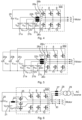
- a battery 1 with a voltage V B , is connected to a DC-link (illustrated as a voltage source inverter VSI) through a DC/DC converter (illustrated as a boost converter BC).
- the battery 1 may alternatively be connected directly to the VSI.
- EV electrical vehicle
- supercapacitors have been used to extend the battery lifetime, and thus the lifetime of the entire system.
- a supercapacitor 5 is provided in BC and/or a supercapacitor 6 in the VSI, for buffering high-power peaks from acceleration and regenerative breaking.
- the BC comprises an inductor 2 connected to the battery 1 and to MOSFET 4 connected to the VSI as well as to the supercapacitor 5.
- the inductor 2 is further connected to MOSFET 3.
- the VSI comprises MOSFETs 7-12 arranged to provide the motor voltages V a -V c .
- the common practice is to have another DC/DC converter to interface the supercapacitor, i.e. two BCs will be utilized as follows: one BC for the battery and one BC for the supercapacitor, where the output of both DC/DC converters will be connected in parallel to the VSI as shown in Fig. 1B .
- a supercapacitor BC is added in parallel to the powertrain illustrated in Fig. 1A , for buffering high-power peaks from acceleration and regenerative breaking.
- the supercapacitor BC comprises an inductor 14 connected to a battery 13 and to MOSFET 16 connected to the VSI as well as to supercapacitor 17.
- the inductor 14 is further connected to MOSFET 15.
- a supercapacitor also called an ultracapacitor
- SC is a high-capacity capacitor with a capacitance value much higher than other capacitors, but with lower voltage limits, that bridges the gap between electrolytic capacitors and rechargeable batteries. It typically stores 10 to 100 times more energy per unit volume or mass than electrolytic capacitors, can accept and deliver charge much faster than batteries with much higher current capabilities, and tolerates many more charge and discharge cycles than rechargeable batteries.
- supercapacitors do not use conventional solid dielectric, but rather, they use electrostatic double-layer capacitance and electrochemical pseudo-capacitance, both of which contribute to the total capacitance of the capacitor, with a few differences.
- Electrostatic double-layer capacitors use carbon electrodes or derivatives with much higher electrostatic double-layer capacitance than electrochemical pseudo-capacitance, achieving separation of charge in a Helmholtz double layer at the interface between the surface of a conductive electrode and an electrolyte.
- the separation of charge is of the order of a few ⁇ ngström (0.3-0.8 nm), much smaller than in a conventional capacitor.
- Electrochemical pseudo-capacitors use metal oxide or conducting polymer electrodes with a high amount of electrochemical pseudo-capacitance additional to the double-layer capacitance. Pseudo-capacitance is achieved by Faradaic electron charge-transfer with redox reactions, intercalation or electrosorption.
- Hybrid capacitors such as a lithium-ion capacitor, use electrodes with differing characteristics: one exhibiting mostly electrostatic capacitance and the other mostly electrochemical capacitance.
- the electrolyte forms an ionic conductive connection between the two electrodes which distinguishes them from conventional electrolytic capacitors where a dielectric layer always exists, and the so-called electrolyte, e.g., MnO 2 or conducting polymer, is in fact part of the second electrode (the cathode, or more correctly the positive electrode).
- electrolyte e.g., MnO 2 or conducting polymer
- supercapacitors are polarized by design with asymmetric electrodes, or, for symmetric electrodes, by a potential applied during manufacture.
- WO 2011/078577 discloses a power-converting apparatus for a hybrid industrial vehicle using an existing DC/DC converter to initially charge an ultracapacitor to prevent inrush current caused by electric potential difference flowing from a battery towards the ultracapacitor when a hybrid electric forklift truck starts operating.
- EP 3 293 036 discloses a system for power transfer between batteries of a composite AGV allowing bidirectional charging from a battery to another.
- US 10 381 951 discloses a similar use of SSI and supercapacitor.
- DE 10 2018 009848 discloses connection of a charger to a motor middle point
- DE 10 2017 221365 discloses connection of a charger to a motor middle point or to the output of an inverter.
- One objective of the present invention is to integrate a battery and a supercapacitor in an onboard powertrain for an automated guided vehicle (AGV) without the need of the additional DC/DC converter to enable a compact system design.
- AGV automated guided vehicle
- Each electrical phase may be connected to an individual middle point pole.
- the onboard powertrain may further comprise a battery and an inductor connected in series between the common negative DC-link pole and each middle point pole. All electrical phases may be connected to a common middle point pole.
- the onboard powertrain may further comprise a semiconductor element between the common middle point pole and each electrical phase.
- the semiconductor element may be a diode or a MOSFET.
- the battery may be connected closer to the common negative DC-link pole than to the inductor.
- the onboard powertrain may further comprise an onboard charger with a step-down transformer.
- the onboard charger may be connected to the electrical phases of the SSI via switches and inductances.
- the onboard charger may connected separately to individual middle point poles.
- the onboard charger may be connected to a common middle point pole.
- the capacitance of at least one supercapacitor may be at least 1 mJ/mm 3 .
- the capacitance of each supercapacitor may be at least 1 farad (F), such as at least 10 F or at least 100 F.
- the supercapacitor is connected to the DC-link terminals, to allow peak load shaving and buffering for the battery.
- a modular design is also made possible by integrating the switch into the SSI.
- the motor may further be driven to varying the DC-link voltage.
- the DC-link will further have less voltage variations, since the battery is connected directly to the DC-link and the supercapacitor is arranged to inject high current only.
- FIG. 2A and 2B An embodiment of an onboard powertrain for an AGV is presented with reference to Figs. 2A and 2B .
- the embodiment presents an efficient topology to integrate a battery and a supercapacitor with a diode-inductor set to provide a split-source inverter (SSI), utilizing a two-level converter available on the shelf.
- SSI split-source inverter
- a supercapacitor 20 is connected to a DC-link of the three-phase SSI, i.e. between a positive and negative pole of the DC-link.
- a battery 21, configured to drive a three-phase AGV, is connected between a middle point of the SSI via an inductor 22 and the negative ( Fig. 2A ) or positive ( Fig. 2B ) pole of the DC-link for the motor drive of the AGV.
- the middle point of the SSI is connected to a diode 23 per phase of the three-phase SSI, each phase being connected to a respective AC terminal, V a , V b , V c , of the motor.
- the SSI further comprises MOSFETs 7-12 arranged to provide the motor voltages V a -V c .
- Both the battery current and the supercapacitor current can thus be controlled by the SSI so that only smooth DC-current is taken from/fed to the battery and fluctuating current is buffered by the supercapacitor, which has better cycling capability and less internal loss.
- the battery lifetime can be extended while the lifetime of the supercapacitor is significantly longer than the battery and is not a concern.
- the energy from regenerative break can be buffered to extend the recharge mileage.
- the energy from regenerative break is buffered in the supercapacitor, which voltage will build up and which is designed to handle such case.
- the energy stored in the supercapacitor is then injected again to the load during acceleration.
- the DC-link voltage of the system may vary between 48 V and 24 V in order to allow the high current injection or absorption from the motor.
- the SSI, battery and supercapacitor can all each be made of standard commercial products.
- the inductor with diodes may alternatively be integrated as one piece instead of being a standard product connected to a standard SSI.
- the topology can be realized with minimum design modification of a typical onboard powertrain of an AGV.
- Fig. 3 illustrates an embodiment with a topology where the diodes 23 and 24 of Figs. 2A and 2B are replaced by MOSFETs 25 to allow a bi-directional power flow.
- the MOSFET 25 work in synchronized rectification mode and switches at the fundamental frequency according to the motor requirements.
- Fig. 4 illustrates an embodiment with a topology in which the battery 21 of Fig. 3 is divided into 3 modules, V B1 , V B2 , V B3 , wherein each module is connected between the negative DC-link pole and one of the AC terminals V a , V b , V c , via switches 26 a , 26 b , 26 c .
- Switches 26 a , 26 b , 26 c can be diodes, MOSFETs, or diodes with MOSFETs in series for full controllability. Switches 26 a , 26 b , 26 c may also be relays to enable only one of these batteries.
- Fig. 5 illustrates an embodiment with a topology in which also the supercapacitor 20 is split into 3 modules V SC1 , V SC2 , V SC3 in the same way as the battery illustrated in Fig. 4 , so that each phase of the motor is connected to a half-bridge.
- Fig. 6 illustrates an embodiment with an onboard charger for the topology of Fig. 3 .
- An external AC-source is via a step-down transformer 29 connectable to the phases V a , V b , V c of the SSI via switches 28 and inductances 27.
- the motor is connectable via switches 30. The motor is disconnected when the battery 21 is charged via the external AC-source.
- the onboard charger is illustrated as connected to the three-phase terminals but can alternatively be connected to the common middle point pole as a single-phase charger instead.
- a relay or contactor can be used to avoid direct connection between the transformer and the motor.
- the switched may be MOSFETs as one alternative option, under which the onboard charger can be just a step-down transformer without much complexity, resulting in reduced system cost.
- Selection of topology for a specific implementation may be dependent on the internal layout design of the AGV (i.e. space requirement) and required functionality.
- the onboard powertrain comprises an SSI, a middle point pole per electrical phase of the SSI, a positive DC-link pole, and a negative DC-link pole, a battery 21 and an inductor 22 connected in series between the positive or negative DC-link pole and the middle point pole, and a supercapacitor 20 connected between the positive and negative DC-link poles.
- the onboard powertrain is configured to generate a plurality of electrical phases. There may be three electrical phases V a , V b , V c .
- Each electrical phase V a , V b , V c is connected to an individual middle point pole.
- the onboard powertrain may further comprise a battery 21 and an inductor 22 connected in series between the positive or negative DC-link pole and each middle point pole.
- the battery(ies) may be connected closer to the common negative DC-link pole than to the inductor.
- the onboard powertrain comprises a supercapacitor per electrical phase V a , V b , V c of the SSI, each connected between a common negative DC-link pole for the SSI and a separate positive DC-link pole per phase of the SSI.
- the onboard powertrain may further comprise an onboard charger with a step-down transformer.
- the onboard charger may be connected to the electrical phases V a , V b , V c of the SSI via switches and inductances.
- the onboard charger may be connected separately to individual middle point poles.
- the capacitance of at least one supercapacitor 20 may be at least 1 mJ/mm 3 .
- each supercapacitor 20 may be at least 1 farad (F), or may be at least 10 F, or may be at least 100 F.
- the onboard powertrain comprises an SSI having a common middle point pole, a positive DC-link pole, and a negative DC-link pole, a battery 21 and an inductor 22 connected in series between the positive or negative DC-link pole and the common middle point pole, and a supercapacitor 20 connected between the positive and negative DC-link poles.
- the onboard powertrain is configured to generate a plurality of electrical phases. There may be three electrical phases V a , V b , V c .
- the onboard powertrain may further comprise a semiconductor element 23, 24, 25 between the common middle point pole and each electrical phase V a , V b , V c .
- the semiconductor element may be a diode 23, 24 or a MOSFET 25.
- the battery 21 may be connected closer to the common negative DC-link pole than to the inductor 22.
- the onboard powertrain comprises a supercapacitor 20 per electrical phase V a , V b , V c of the SSI, each connected between a common negative DC-link pole for the SSI and a separate positive DC-link pole per phase of the SSI.
- the onboard powertrain may further comprise an off-board charger with a step-down transformer 29.
- the onboard charger may be connected to the electrical phases V a , V b , V c of the SSI via switches 28 and inductances 27.
- the onboard charger may be connected to a common middle point pole.
- the capacitance of at least one supercapacitor 20 may be at least 1 mJ/mm 3 .
- each supercapacitor 20 is at least 1 F, ), or may be at least 10 F, or may be at least 100 F.
Landscapes
- Engineering & Computer Science (AREA)
- Power Engineering (AREA)
- Transportation (AREA)
- Mechanical Engineering (AREA)
- Life Sciences & Earth Sciences (AREA)
- Sustainable Development (AREA)
- Sustainable Energy (AREA)
- Charge And Discharge Circuits For Batteries Or The Like (AREA)
- Electric Propulsion And Braking For Vehicles (AREA)
Claims (13)
- Bordantriebsstrang für ein Fahrerloses Transportfahrzeug (FTF / Automated Guided Vehicle, AGV), wobei der Bordantriebsstrang umfasst:- einen Wechselrichter mit geteilter Quelle, SSI, mit einer Mehrzahl von elektrischen Phasen (Va, Vb, Vc), wie beispielsweise drei elektrischen Phasen (Va, Vb, Vc), mit zumindest einem Mittelpunktpol, einem separaten positiven DC-Link-Pol pro Phase des SSI und einem gemeinsamen negativen DC-Link-Pol; und- eine Batterie (21) und eine Drosselspule (22), die in Reihe zwischen dem gemeinsamen negativen Pol des DC-Links und dem Mittelpunktpol geschaltet sind; gekennzeichnet durcheinen Superkondensator pro elektrischer Phase (Va, Vb, Vc) des SSI, die jeweils zwischen dem gemeinsamen negativen DC-Link-Pol für den SSI und dem separaten positiven DC-Link-Pol pro Phase des SSI verbunden sind.
- Bordantriebsstrang nach Anspruch 1, wobei jede elektrische Phase (Va, Vb, Vc) mit einem individuellen Mittelpunktpol verbunden ist.
- Bordantriebsstrang nach Anspruch 2, der ferner eine Batterie (21) und eine Drosselspule (22) umfasst, die zwischen dem gemeinsamen negativen DC-Link-Pol und jedem Mittelpunktpol in Reihe geschaltet sind.
- Bordantriebsstrang nach Anspruch 1, wobei alle elektrischen Phasen mit einem gemeinsamen Mittelpunktpol verbunden sind.
- Bordantriebsstrang nach Anspruch 4, der ferner ein Halbleiterelement (23; 24; 25) zwischen dem gemeinsamen Mittelpunktpol und jeder elektrischen Phase umfasst.
- Bordantriebsstrang nach Anspruch 5, wobei das Halbleiterelement eine Diode (23; 24) oder ein MOSFET (25) ist.
- Bordantriebsstrang nach einem der vorhergehenden Ansprüche, wobei die Batterie näher mit dem gemeinsamen negativen DC-Link-Pol verbunden ist als mit der Drosselspule.
- Bordantriebsstrang nach einem der vorhergehenden Ansprüche, der ferner ein Bordladegerät mit einem Abwärtstransformator (29) umfasst.
- Bordantriebsstrang nach Anspruch 8, wobei das Bordladegerät über Schalter (28) und Induktivitäten (27) mit den elektrischen Phasen (Va, Vb, Vc) des SSI verbunden ist.
- Bordantriebsstrang nach einem der Ansprüche 8 und 9, wobei das Bordladegerät separat mit einzelnen Mittelpunktpolen verbunden ist.
- Bordantriebsstrang nach einem der Ansprüche 8 und 9, wobei das Bordladegerät mit einem gemeinsamen Mittelpunktpol verbunden ist.
- Bordantriebsstrang nach einem der vorhergehenden Ansprüche, wobei die Kapazität von mindestens einem Superkondensator (20) mindestens 1 mJ/mm3 beträgt.
- Bordantriebsstrang nach Anspruch 12, wobei die Kapazität jedes Superkondensators (20) mindestens 1 Farad (F), wie beispielsweise mindestens 10 F oder mindestens 100 F beträgt.
Priority Applications (1)
| Application Number | Priority Date | Filing Date | Title |
|---|---|---|---|
| PL19812766.4T PL4065405T3 (pl) | 2019-11-27 | 2019-11-27 | Pokładowy układ napędowy dla pojazdu sterowanego automatycznie (agv) |
Applications Claiming Priority (1)
| Application Number | Priority Date | Filing Date | Title |
|---|---|---|---|
| PCT/EP2019/082759 WO2021104621A1 (en) | 2019-11-27 | 2019-11-27 | Onboard powertrain for agv |
Publications (3)
| Publication Number | Publication Date |
|---|---|
| EP4065405A1 EP4065405A1 (de) | 2022-10-05 |
| EP4065405B1 true EP4065405B1 (de) | 2024-08-07 |
| EP4065405C0 EP4065405C0 (de) | 2024-08-07 |
Family
ID=68731994
Family Applications (1)
| Application Number | Title | Priority Date | Filing Date |
|---|---|---|---|
| EP19812766.4A Active EP4065405B1 (de) | 2019-11-27 | 2019-11-27 | Bordantriebsstrang für agv |
Country Status (6)
| Country | Link |
|---|---|
| US (1) | US12005795B2 (de) |
| EP (1) | EP4065405B1 (de) |
| CN (1) | CN114728593B (de) |
| ES (1) | ES2992147T3 (de) |
| PL (1) | PL4065405T3 (de) |
| WO (1) | WO2021104621A1 (de) |
Families Citing this family (4)
| Publication number | Priority date | Publication date | Assignee | Title |
|---|---|---|---|---|
| EP4170879B1 (de) * | 2021-10-22 | 2024-07-17 | Abb Schweiz Ag | Abwärtsunterstützter split-source-wandler |
| FR3129544A1 (fr) * | 2021-11-25 | 2023-05-26 | IFP Energies Nouvelles | Convertisseur d’énergie électrique apte à être connecté à deux sources d’alimentation et apte à la récupération d’énergie |
| CN116633185B (zh) * | 2023-07-19 | 2023-11-10 | 南京理工大学 | 一种升压型并网逆变器及其控制方法 |
| CN117811402B (zh) * | 2023-12-27 | 2025-02-14 | 南京理工大学 | 一种升压型三端口储能逆变器及其控制方法 |
Citations (6)
| Publication number | Priority date | Publication date | Assignee | Title |
|---|---|---|---|---|
| DE19742429C1 (de) * | 1997-09-25 | 1999-01-07 | Siemens Ag | Schaltungsanordnung |
| US7605497B2 (en) * | 2007-06-08 | 2009-10-20 | Gm Global Technology Operations, Inc. | Two-source inverter |
| EP1615325B1 (de) * | 2004-07-07 | 2015-04-22 | Nissan Motor Co., Ltd. | Stromwandlung und Fahrzeug |
| EP2863528A1 (de) * | 2013-10-16 | 2015-04-22 | Siemens Aktiengesellschaft | Einsatz eines Wechselrichters als Gleichstrom-Wander |
| RU2555746C1 (ru) * | 2014-02-06 | 2015-07-10 | Общество с ограниченной ответственностью "Супервариатор" | Блок преобразователей для силовой установки с двигателем внутреннего сгорания и электромеханической трансмиссией |
| JP2017046467A (ja) * | 2015-08-27 | 2017-03-02 | 株式会社日立製作所 | 電力変換装置 |
Family Cites Families (9)
| Publication number | Priority date | Publication date | Assignee | Title |
|---|---|---|---|---|
| KR101653837B1 (ko) | 2009-12-24 | 2016-09-02 | 두산인프라코어 주식회사 | 하이브리드 산업용 차량의 전력변환장치 |
| US8599577B2 (en) * | 2010-11-08 | 2013-12-03 | GM Global Technology Operations LLC | Systems and methods for reducing harmonic distortion in electrical converters |
| US9825470B2 (en) | 2012-10-25 | 2017-11-21 | Mcmaster University | Multi-source power converter |
| CN102923537B (zh) * | 2012-11-13 | 2014-04-23 | 天津大学 | 超级电容储能式电梯一体化驱动控制装置 |
| PL3293036T3 (pl) | 2016-09-07 | 2022-01-03 | In2Power Nv | Przenoszenie energii z akumulatora nadrzędnego do akumulatora podrzędnego dla układów złożonych |
| CA2983328C (en) * | 2017-06-15 | 2021-09-21 | The Governing Council Of The University Of Toronto | Constant current fast charging of electric vehicles via dc grid using dual inverter drive |
| DE102017221365A1 (de) | 2017-11-29 | 2019-05-29 | Continental Automotive Gmbh | Fahrzeugbordnetz mit Wechselrichter, Energiespeicher, elektrischer Maschine und Wechselstrom-Übertragungsanschluss |
| US10381951B1 (en) * | 2018-11-30 | 2019-08-13 | The Florida International University Board Of Trustees | Family of modular quasi-resonant inverters |
| DE102018009848A1 (de) | 2018-12-14 | 2019-06-27 | Daimler Ag | Schaltungsanordnung für ein Kraftfahrzeug, insbesondere für ein Hybrid- oder Elektrofahrzeug |
-
2019
- 2019-11-27 EP EP19812766.4A patent/EP4065405B1/de active Active
- 2019-11-27 CN CN201980102250.7A patent/CN114728593B/zh active Active
- 2019-11-27 US US17/755,363 patent/US12005795B2/en active Active
- 2019-11-27 WO PCT/EP2019/082759 patent/WO2021104621A1/en not_active Ceased
- 2019-11-27 ES ES19812766T patent/ES2992147T3/es active Active
- 2019-11-27 PL PL19812766.4T patent/PL4065405T3/pl unknown
Patent Citations (6)
| Publication number | Priority date | Publication date | Assignee | Title |
|---|---|---|---|---|
| DE19742429C1 (de) * | 1997-09-25 | 1999-01-07 | Siemens Ag | Schaltungsanordnung |
| EP1615325B1 (de) * | 2004-07-07 | 2015-04-22 | Nissan Motor Co., Ltd. | Stromwandlung und Fahrzeug |
| US7605497B2 (en) * | 2007-06-08 | 2009-10-20 | Gm Global Technology Operations, Inc. | Two-source inverter |
| EP2863528A1 (de) * | 2013-10-16 | 2015-04-22 | Siemens Aktiengesellschaft | Einsatz eines Wechselrichters als Gleichstrom-Wander |
| RU2555746C1 (ru) * | 2014-02-06 | 2015-07-10 | Общество с ограниченной ответственностью "Супервариатор" | Блок преобразователей для силовой установки с двигателем внутреннего сгорания и электромеханической трансмиссией |
| JP2017046467A (ja) * | 2015-08-27 | 2017-03-02 | 株式会社日立製作所 | 電力変換装置 |
Non-Patent Citations (5)
| Title |
|---|
| ABDELHAKIM AHMED ET AL: "Split-source inverter", IECON 2015 - 41ST ANNUAL CONFERENCE OF THE IEEE INDUSTRIAL ELECTRONICS SOCIETY, IEEE, 9 November 2015 (2015-11-09), pages 1288 - 1293, XP032855390, DOI: 10.1109/IECON.2015.7392278 * |
| BOSCAINO VALERIA ET AL: "Decoupled control scheme of the grid-connected split-source inverter for renewable energy sources", IECON 2016 - 42ND ANNUAL CONFERENCE OF THE IEEE INDUSTRIAL ELECTRONICS SOCIETY, IEEE, 23 October 2016 (2016-10-23), pages 3317 - 3322, XP033033756, DOI: 10.1109/IECON.2016.7793554 * |
| RAMOUL JOHN ET AL: "A Neural Network Energy Management Controller Applied to a Hybrid Energy Storage System using Multi-Source Inverter", 2018 IEEE ENERGY CONVERSION CONGRESS AND EXPOSITION (ECCE), IEEE, 23 September 2018 (2018-09-23), pages 2741 - 2747, XP033464367, DOI: 10.1109/ECCE.2018.8558326 * |
| SALARI O ET AL: "A Multi-Source Inverter for Electric Drive Vehicles", 2018 IEEE ENERGY CONVERSION CONGRESS AND EXPOSITION (ECCE), IEEE, 23 September 2018 (2018-09-23), pages 3872 - 3879, XP033463797, DOI: 10.1109/ECCE.2018.8557729 * |
| YOGESH MAHADIK ET AL: "Battery Life Enhancement in a Hybrid Electrical Energy Storage System Using a Multi-Source Inverter", WORLD ELECTRIC VEHICLE JOURNAL, vol. 10, no. 2, 12 April 2019 (2019-04-12), pages 17, XP055688513, DOI: 10.3390/wevj10020017 * |
Also Published As
| Publication number | Publication date |
|---|---|
| CN114728593A (zh) | 2022-07-08 |
| EP4065405C0 (de) | 2024-08-07 |
| ES2992147T3 (es) | 2024-12-09 |
| CN114728593B (zh) | 2025-07-11 |
| EP4065405A1 (de) | 2022-10-05 |
| PL4065405T3 (pl) | 2024-12-23 |
| US12005795B2 (en) | 2024-06-11 |
| US20220379753A1 (en) | 2022-12-01 |
| WO2021104621A1 (en) | 2021-06-03 |
Similar Documents
| Publication | Publication Date | Title |
|---|---|---|
| EP4065405B1 (de) | Bordantriebsstrang für agv | |
| CN106476635B (zh) | 具有多个能量存储装置的混合系统 | |
| US8193761B1 (en) | Hybrid power source | |
| US9809128B2 (en) | System for multiple energy storage and management and method of making same | |
| KR101822656B1 (ko) | 기계 장비를 구동하기 위한 전기 장치 및 관련 방법 | |
| CN103580214B (zh) | 充电装置及其操作方法 | |
| Andreev | An overview of supercapacitors as new power sources in hybrid energy storage systems for electric vehicles | |
| EP2284037A2 (de) | System zur mehrfachen Energiespeicherung und -verwaltung sowie Herstellungsverfahren dafür | |
| US8829719B2 (en) | System for multiple energy storage and management and method of making same | |
| KR101865246B1 (ko) | 전기자동차용 충방전 장치 | |
| AU2013393504A1 (en) | Hybrid drive system | |
| JP2018530989A (ja) | 再構成可能容量性エネルギー貯蔵デバイス、電力供給システムおよびこのデバイスが組み込まれた電気移動体 | |
| CN119604429A (zh) | 具有电力电路装置和两个电驱动单元的车辆及其运行方法 | |
| CN102848931A (zh) | 一种电动汽车能量源系统结构 | |
| CN116054577A (zh) | 用于电动车辆的能量系统 | |
| CN108136931B (zh) | 改进的带有多个电源的电源装置 | |
| Ellabban et al. | Z-source inverter for vehicular applications | |
| CN105059129A (zh) | 复合电源、使用该复合电源的供能系统及电动汽车 | |
| Sayed et al. | Advanced super capacitor based converter for power regeneration of electric vehicle applications | |
| GB2592244A (en) | Charging system | |
| CN102355038A (zh) | 一种高压直流充电机 | |
| CN116054576A (zh) | 用于电动车辆的能量系统 | |
| JP2018033262A (ja) | 電圧変換装置 | |
| Alam | Regenerative braking and rapid acceleration system for electric vehicles using integrated battery and supercapacitor | |
| JP5077489B2 (ja) | 蓄電装置及び鉄道車両 |
Legal Events
| Date | Code | Title | Description |
|---|---|---|---|
| STAA | Information on the status of an ep patent application or granted ep patent |
Free format text: STATUS: UNKNOWN |
|
| STAA | Information on the status of an ep patent application or granted ep patent |
Free format text: STATUS: THE INTERNATIONAL PUBLICATION HAS BEEN MADE |
|
| PUAI | Public reference made under article 153(3) epc to a published international application that has entered the european phase |
Free format text: ORIGINAL CODE: 0009012 |
|
| STAA | Information on the status of an ep patent application or granted ep patent |
Free format text: STATUS: REQUEST FOR EXAMINATION WAS MADE |
|
| 17P | Request for examination filed |
Effective date: 20220413 |
|
| AK | Designated contracting states |
Kind code of ref document: A1 Designated state(s): AL AT BE BG CH CY CZ DE DK EE ES FI FR GB GR HR HU IE IS IT LI LT LU LV MC MK MT NL NO PL PT RO RS SE SI SK SM TR |
|
| DAV | Request for validation of the european patent (deleted) | ||
| DAX | Request for extension of the european patent (deleted) | ||
| RIC1 | Information provided on ipc code assigned before grant |
Ipc: H02M 7/5387 20070101ALI20240227BHEP Ipc: H02M 3/158 20060101ALI20240227BHEP Ipc: H02M 1/00 20060101ALI20240227BHEP Ipc: B60L 7/14 20060101ALI20240227BHEP Ipc: B60L 15/00 20060101ALI20240227BHEP Ipc: B60L 50/40 20190101ALI20240227BHEP Ipc: B60L 50/60 20190101ALI20240227BHEP Ipc: B60L 53/14 20190101ALI20240227BHEP Ipc: B60L 58/21 20190101ALI20240227BHEP Ipc: H02M 3/00 20060101ALI20240227BHEP Ipc: H02M 7/797 20060101ALI20240227BHEP Ipc: B60L 7/10 20060101AFI20240227BHEP |
|
| GRAP | Despatch of communication of intention to grant a patent |
Free format text: ORIGINAL CODE: EPIDOSNIGR1 |
|
| STAA | Information on the status of an ep patent application or granted ep patent |
Free format text: STATUS: GRANT OF PATENT IS INTENDED |
|
| INTG | Intention to grant announced |
Effective date: 20240405 |
|
| GRAS | Grant fee paid |
Free format text: ORIGINAL CODE: EPIDOSNIGR3 |
|
| GRAA | (expected) grant |
Free format text: ORIGINAL CODE: 0009210 |
|
| STAA | Information on the status of an ep patent application or granted ep patent |
Free format text: STATUS: THE PATENT HAS BEEN GRANTED |
|
| AK | Designated contracting states |
Kind code of ref document: B1 Designated state(s): AL AT BE BG CH CY CZ DE DK EE ES FI FR GB GR HR HU IE IS IT LI LT LU LV MC MK MT NL NO PL PT RO RS SE SI SK SM TR |
|
| REG | Reference to a national code |
Ref country code: GB Ref legal event code: FG4D |
|
| REG | Reference to a national code |
Ref country code: CH Ref legal event code: EP |
|
| REG | Reference to a national code |
Ref country code: IE Ref legal event code: FG4D |
|
| REG | Reference to a national code |
Ref country code: DE Ref legal event code: R096 Ref document number: 602019056669 Country of ref document: DE |
|
| U01 | Request for unitary effect filed |
Effective date: 20240819 |
|
| RAP4 | Party data changed (patent owner data changed or rights of a patent transferred) |
Owner name: ABB SCHWEIZ AG |
|
| U07 | Unitary effect registered |
Designated state(s): AT BE BG DE DK EE FI FR IT LT LU LV MT NL PT RO SE SI Effective date: 20240910 |
|
| REG | Reference to a national code |
Ref country code: ES Ref legal event code: FG2A Ref document number: 2992147 Country of ref document: ES Kind code of ref document: T3 Effective date: 20241209 |
|
| U20 | Renewal fee for the european patent with unitary effect paid |
Year of fee payment: 6 Effective date: 20241126 |
|
| PG25 | Lapsed in a contracting state [announced via postgrant information from national office to epo] |
Ref country code: NO Free format text: LAPSE BECAUSE OF FAILURE TO SUBMIT A TRANSLATION OF THE DESCRIPTION OR TO PAY THE FEE WITHIN THE PRESCRIBED TIME-LIMIT Effective date: 20241107 |
|
| PG25 | Lapsed in a contracting state [announced via postgrant information from national office to epo] |
Ref country code: GR Free format text: LAPSE BECAUSE OF FAILURE TO SUBMIT A TRANSLATION OF THE DESCRIPTION OR TO PAY THE FEE WITHIN THE PRESCRIBED TIME-LIMIT Effective date: 20241108 |
|
| PG25 | Lapsed in a contracting state [announced via postgrant information from national office to epo] |
Ref country code: IS Free format text: LAPSE BECAUSE OF FAILURE TO SUBMIT A TRANSLATION OF THE DESCRIPTION OR TO PAY THE FEE WITHIN THE PRESCRIBED TIME-LIMIT Effective date: 20241207 |
|
| PG25 | Lapsed in a contracting state [announced via postgrant information from national office to epo] |
Ref country code: HR Free format text: LAPSE BECAUSE OF FAILURE TO SUBMIT A TRANSLATION OF THE DESCRIPTION OR TO PAY THE FEE WITHIN THE PRESCRIBED TIME-LIMIT Effective date: 20240807 |
|
| PG25 | Lapsed in a contracting state [announced via postgrant information from national office to epo] |
Ref country code: RS Free format text: LAPSE BECAUSE OF FAILURE TO SUBMIT A TRANSLATION OF THE DESCRIPTION OR TO PAY THE FEE WITHIN THE PRESCRIBED TIME-LIMIT Effective date: 20241107 |
|
| PG25 | Lapsed in a contracting state [announced via postgrant information from national office to epo] |
Ref country code: RS Free format text: LAPSE BECAUSE OF FAILURE TO SUBMIT A TRANSLATION OF THE DESCRIPTION OR TO PAY THE FEE WITHIN THE PRESCRIBED TIME-LIMIT Effective date: 20241107 Ref country code: NO Free format text: LAPSE BECAUSE OF FAILURE TO SUBMIT A TRANSLATION OF THE DESCRIPTION OR TO PAY THE FEE WITHIN THE PRESCRIBED TIME-LIMIT Effective date: 20241107 Ref country code: IS Free format text: LAPSE BECAUSE OF FAILURE TO SUBMIT A TRANSLATION OF THE DESCRIPTION OR TO PAY THE FEE WITHIN THE PRESCRIBED TIME-LIMIT Effective date: 20241207 Ref country code: HR Free format text: LAPSE BECAUSE OF FAILURE TO SUBMIT A TRANSLATION OF THE DESCRIPTION OR TO PAY THE FEE WITHIN THE PRESCRIBED TIME-LIMIT Effective date: 20240807 Ref country code: GR Free format text: LAPSE BECAUSE OF FAILURE TO SUBMIT A TRANSLATION OF THE DESCRIPTION OR TO PAY THE FEE WITHIN THE PRESCRIBED TIME-LIMIT Effective date: 20241108 |
|
| PG25 | Lapsed in a contracting state [announced via postgrant information from national office to epo] |
Ref country code: SM Free format text: LAPSE BECAUSE OF FAILURE TO SUBMIT A TRANSLATION OF THE DESCRIPTION OR TO PAY THE FEE WITHIN THE PRESCRIBED TIME-LIMIT Effective date: 20240807 |
|
| PG25 | Lapsed in a contracting state [announced via postgrant information from national office to epo] |
Ref country code: CZ Free format text: LAPSE BECAUSE OF FAILURE TO SUBMIT A TRANSLATION OF THE DESCRIPTION OR TO PAY THE FEE WITHIN THE PRESCRIBED TIME-LIMIT Effective date: 20240807 |
|
| PG25 | Lapsed in a contracting state [announced via postgrant information from national office to epo] |
Ref country code: SK Free format text: LAPSE BECAUSE OF FAILURE TO SUBMIT A TRANSLATION OF THE DESCRIPTION OR TO PAY THE FEE WITHIN THE PRESCRIBED TIME-LIMIT Effective date: 20240807 |
|
| PLBE | No opposition filed within time limit |
Free format text: ORIGINAL CODE: 0009261 |
|
| STAA | Information on the status of an ep patent application or granted ep patent |
Free format text: STATUS: NO OPPOSITION FILED WITHIN TIME LIMIT |
|
| REG | Reference to a national code |
Ref country code: CH Ref legal event code: PL |
|
| PG25 | Lapsed in a contracting state [announced via postgrant information from national office to epo] |
Ref country code: MC Free format text: LAPSE BECAUSE OF FAILURE TO SUBMIT A TRANSLATION OF THE DESCRIPTION OR TO PAY THE FEE WITHIN THE PRESCRIBED TIME-LIMIT Effective date: 20240807 |
|
| REG | Reference to a national code |
Ref country code: CH Ref legal event code: PL |
|
| 26N | No opposition filed |
Effective date: 20250508 |
|
| PG25 | Lapsed in a contracting state [announced via postgrant information from national office to epo] |
Ref country code: CH Free format text: LAPSE BECAUSE OF NON-PAYMENT OF DUE FEES Effective date: 20241130 |
|
| PG25 | Lapsed in a contracting state [announced via postgrant information from national office to epo] |
Ref country code: IE Free format text: LAPSE BECAUSE OF NON-PAYMENT OF DUE FEES Effective date: 20241127 |
|
| U20 | Renewal fee for the european patent with unitary effect paid |
Year of fee payment: 7 Effective date: 20251127 |
|
| PGFP | Annual fee paid to national office [announced via postgrant information from national office to epo] |
Ref country code: GB Payment date: 20251121 Year of fee payment: 7 |
|
| PGFP | Annual fee paid to national office [announced via postgrant information from national office to epo] |
Ref country code: PL Payment date: 20251117 Year of fee payment: 7 |
|
| PGFP | Annual fee paid to national office [announced via postgrant information from national office to epo] |
Ref country code: ES Payment date: 20251229 Year of fee payment: 7 |