EP4065377B1 - Vorrichtung zur behandlung von mehreren oberflächen von gegenständen und entsprechendes behandlungsverfahren - Google Patents
Vorrichtung zur behandlung von mehreren oberflächen von gegenständen und entsprechendes behandlungsverfahren Download PDFInfo
- Publication number
- EP4065377B1 EP4065377B1 EP20815954.1A EP20815954A EP4065377B1 EP 4065377 B1 EP4065377 B1 EP 4065377B1 EP 20815954 A EP20815954 A EP 20815954A EP 4065377 B1 EP4065377 B1 EP 4065377B1
- Authority
- EP
- European Patent Office
- Prior art keywords
- shuttle
- location
- card
- objects
- locations
- Prior art date
- Legal status (The legal status is an assumption and is not a legal conclusion. Google has not performed a legal analysis and makes no representation as to the accuracy of the status listed.)
- Active
Links
Images


Classifications
-
- B—PERFORMING OPERATIONS; TRANSPORTING
- B41—PRINTING; LINING MACHINES; TYPEWRITERS; STAMPS
- B41J—TYPEWRITERS; SELECTIVE PRINTING MECHANISMS, i.e. MECHANISMS PRINTING OTHERWISE THAN FROM A FORME; CORRECTION OF TYPOGRAPHICAL ERRORS
- B41J3/00—Typewriters or selective printing or marking mechanisms characterised by the purpose for which they are constructed
- B41J3/60—Typewriters or selective printing or marking mechanisms characterised by the purpose for which they are constructed for printing on both faces of the printing material
-
- B—PERFORMING OPERATIONS; TRANSPORTING
- B41—PRINTING; LINING MACHINES; TYPEWRITERS; STAMPS
- B41J—TYPEWRITERS; SELECTIVE PRINTING MECHANISMS, i.e. MECHANISMS PRINTING OTHERWISE THAN FROM A FORME; CORRECTION OF TYPOGRAPHICAL ERRORS
- B41J13/00—Devices or arrangements of selective printing mechanisms, e.g. ink-jet printers or thermal printers, specially adapted for supporting or handling copy material in short lengths, e.g. sheets
- B41J13/10—Sheet holders, retainers, movable guides, or stationary guides
- B41J13/12—Sheet holders, retainers, movable guides, or stationary guides specially adapted for small cards, envelopes, or the like, e.g. credit cards, cut visiting cards
-
- B—PERFORMING OPERATIONS; TRANSPORTING
- B41—PRINTING; LINING MACHINES; TYPEWRITERS; STAMPS
- B41J—TYPEWRITERS; SELECTIVE PRINTING MECHANISMS, i.e. MECHANISMS PRINTING OTHERWISE THAN FROM A FORME; CORRECTION OF TYPOGRAPHICAL ERRORS
- B41J3/00—Typewriters or selective printing or marking mechanisms characterised by the purpose for which they are constructed
- B41J3/407—Typewriters or selective printing or marking mechanisms characterised by the purpose for which they are constructed for marking on special material
- B41J3/4073—Printing on three-dimensional objects not being in sheet or web form, e.g. spherical or cubic objects
- B41J3/40731—Holders for objects, e. g. holders specially adapted to the shape of the object to be printed or adapted to hold several objects
-
- B—PERFORMING OPERATIONS; TRANSPORTING
- B65—CONVEYING; PACKING; STORING; HANDLING THIN OR FILAMENTARY MATERIAL
- B65H—HANDLING THIN OR FILAMENTARY MATERIAL, e.g. SHEETS, WEBS, CABLES
- B65H15/00—Overturning articles
-
- B—PERFORMING OPERATIONS; TRANSPORTING
- B65—CONVEYING; PACKING; STORING; HANDLING THIN OR FILAMENTARY MATERIAL
- B65H—HANDLING THIN OR FILAMENTARY MATERIAL, e.g. SHEETS, WEBS, CABLES
- B65H15/00—Overturning articles
- B65H15/016—Overturning articles employing rotary or reciprocating elements supporting transport means
-
- B—PERFORMING OPERATIONS; TRANSPORTING
- B65—CONVEYING; PACKING; STORING; HANDLING THIN OR FILAMENTARY MATERIAL
- B65H—HANDLING THIN OR FILAMENTARY MATERIAL, e.g. SHEETS, WEBS, CABLES
- B65H5/00—Feeding articles separated from piles; Feeding articles to machines
- B65H5/04—Feeding articles separated from piles; Feeding articles to machines by movable tables or carriages
-
- G—PHYSICS
- G06—COMPUTING OR CALCULATING; COUNTING
- G06K—GRAPHICAL DATA READING; PRESENTATION OF DATA; RECORD CARRIERS; HANDLING RECORD CARRIERS
- G06K19/00—Record carriers for use with machines and with at least a part designed to carry digital markings
- G06K19/06—Record carriers for use with machines and with at least a part designed to carry digital markings characterised by the kind of the digital marking, e.g. shape, nature, code
- G06K19/08—Record carriers for use with machines and with at least a part designed to carry digital markings characterised by the kind of the digital marking, e.g. shape, nature, code using markings of different kinds or more than one marking of the same kind in the same record carrier, e.g. one marking being sensed by optical and the other by magnetic means
- G06K19/10—Record carriers for use with machines and with at least a part designed to carry digital markings characterised by the kind of the digital marking, e.g. shape, nature, code using markings of different kinds or more than one marking of the same kind in the same record carrier, e.g. one marking being sensed by optical and the other by magnetic means at least one kind of marking being used for authentication, e.g. of credit or identity cards
- G06K19/14—Record carriers for use with machines and with at least a part designed to carry digital markings characterised by the kind of the digital marking, e.g. shape, nature, code using markings of different kinds or more than one marking of the same kind in the same record carrier, e.g. one marking being sensed by optical and the other by magnetic means at least one kind of marking being used for authentication, e.g. of credit or identity cards the marking being sensed by radiation
- G06K19/145—Record carriers for use with machines and with at least a part designed to carry digital markings characterised by the kind of the digital marking, e.g. shape, nature, code using markings of different kinds or more than one marking of the same kind in the same record carrier, e.g. one marking being sensed by optical and the other by magnetic means at least one kind of marking being used for authentication, e.g. of credit or identity cards the marking being sensed by radiation at least one of the further markings being adapted for galvanic or wireless sensing, e.g. an RFID tag with both a wireless and an optical interface or memory, or a contact type smart card with ISO 7816 contacts and an optical interface or memory
-
- B—PERFORMING OPERATIONS; TRANSPORTING
- B41—PRINTING; LINING MACHINES; TYPEWRITERS; STAMPS
- B41J—TYPEWRITERS; SELECTIVE PRINTING MECHANISMS, i.e. MECHANISMS PRINTING OTHERWISE THAN FROM A FORME; CORRECTION OF TYPOGRAPHICAL ERRORS
- B41J11/00—Devices or arrangements of selective printing mechanisms, e.g. ink-jet printers or thermal printers, for supporting or handling copy material in sheet or web form
- B41J11/0015—Devices or arrangements of selective printing mechanisms, e.g. ink-jet printers or thermal printers, for supporting or handling copy material in sheet or web form for treating before, during or after printing or for uniform coating or laminating the copy material before or after printing
-
- B—PERFORMING OPERATIONS; TRANSPORTING
- B41—PRINTING; LINING MACHINES; TYPEWRITERS; STAMPS
- B41J—TYPEWRITERS; SELECTIVE PRINTING MECHANISMS, i.e. MECHANISMS PRINTING OTHERWISE THAN FROM A FORME; CORRECTION OF TYPOGRAPHICAL ERRORS
- B41J3/00—Typewriters or selective printing or marking mechanisms characterised by the purpose for which they are constructed
- B41J3/407—Typewriters or selective printing or marking mechanisms characterised by the purpose for which they are constructed for marking on special material
-
- B—PERFORMING OPERATIONS; TRANSPORTING
- B65—CONVEYING; PACKING; STORING; HANDLING THIN OR FILAMENTARY MATERIAL
- B65G—TRANSPORT OR STORAGE DEVICES, e.g. CONVEYORS FOR LOADING OR TIPPING, SHOP CONVEYOR SYSTEMS OR PNEUMATIC TUBE CONVEYORS
- B65G47/00—Article or material-handling devices associated with conveyors; Methods employing such devices
- B65G47/22—Devices influencing the relative position or the attitude of articles during transit by conveyors
- B65G47/24—Devices influencing the relative position or the attitude of articles during transit by conveyors orientating the articles
- B65G47/248—Devices influencing the relative position or the attitude of articles during transit by conveyors orientating the articles by turning over or inverting them
-
- B—PERFORMING OPERATIONS; TRANSPORTING
- B65—CONVEYING; PACKING; STORING; HANDLING THIN OR FILAMENTARY MATERIAL
- B65H—HANDLING THIN OR FILAMENTARY MATERIAL, e.g. SHEETS, WEBS, CABLES
- B65H2701/00—Handled material; Storage means
- B65H2701/10—Handled articles or webs
- B65H2701/19—Specific article or web
- B65H2701/1914—Cards, e.g. telephone, credit and identity cards
-
- G—PHYSICS
- G06—COMPUTING OR CALCULATING; COUNTING
- G06K—GRAPHICAL DATA READING; PRESENTATION OF DATA; RECORD CARRIERS; HANDLING RECORD CARRIERS
- G06K13/00—Conveying record carriers from one station to another, e.g. from stack to punching mechanism
- G06K13/02—Conveying record carriers from one station to another, e.g. from stack to punching mechanism the record carrier having longitudinal dimension comparable with transverse dimension, e.g. punched card
- G06K13/07—Transporting of cards between stations
Definitions
- the present invention relates to a treatment device capable of performing treatment on at least two substantially planar faces of objects.
- the invention thus relates in particular to a processing device capable of carrying out processing on both sides of cards.
- It relates in particular, but not exclusively, to a device capable of printing at least two sides of objects, for example both sides of cards.
- This invention applies in particular, but not exclusively, to treatments applied to cards meeting the conditions defined by the ISO 7810 and 7816 standards.
- the invention also relates to a method for processing multiple faces of objects.
- a great many objects have several substantially flat faces.
- a large number of flat objects can be found, such as cards, which essentially have two faces opposite each other.
- the faces of an object that are substantially parallel and oriented in opposite directions are considered to be opposite faces.
- cards most often made of plastic, are now used in multiple applications, for example as a means of payment, or as an official identification document. They can thus have magnetic stripes or electronic chips allowing them to be used as payment cards or bank cards, identification cards, loyalty cards, etc. Most of the cards used are manufactured in compliance with the conditions defined by the ISO 7810 and 7816 standards. These cards are generally rigid or semi-rigid, and are not intended to be folded. This characteristic imposes specific handling conditions for the cards.
- the external appearance of the cards be personalized, for example to display the name of the cardholder, a number, etc.
- This personalization can be achieved by at least one treatment such as printing these characteristics on the faces of the card, for example by a known inkjet printing process or by a laser engraving process. Other treatments, such as sticking a label or varnishing, can be carried out on the faces of the card.
- both sides of each card be printed in a custom way, or undergo the same treatment.
- Such treatment of both sides can be achieved by successively passing the card through two processing equipment, and turning it over between these two equipment.
- Such a process requires the implementation of a bulky and expensive device.
- Processing devices which have a return path for returning a card, after it has passed through a printer, upstream of this printer, so that its second side is printed. Such devices require the installation of return conveyors which increase the volume of the printing device.
- the present invention aims to overcome these drawbacks of the prior art.
- the present invention aims in particular to propose a device capable of processing several faces of an object, and for example the two faces of a card, which has reduced bulk and cost.
- the invention also aims to provide such a device which allows the treatment to be carried out at a high rate.
- Another objective of the invention is to provide such a device which has simple and rapid maintenance.
- the processing equipment performs processing on the faces of the objects only when the latter pass in front of the processing equipment while moving from the first position to the second position of the shuttle.
- the processing equipment it is possible, alternatively or additionally, for the processing equipment to perform processing on the faces of the objects when the latter pass in front of the processing equipment while moving from the second position to the first position of the shuttle.
- the third handling equipment is positioned so as to handle the objects carried by the shuttle when the shuttle is in the second position.
- the movement of the object from the first location to the second location is done downstream of the processing equipment. It is also possible, in other embodiments, for this turning to be done at other positions.
- the shuttle After passing past the processing equipment, the shuttle returns to its first position with the object contained in its first location, and that the removal of this object, its turning over and its placement in the second location are carried out upstream of the equipment, for example near the first position, just before the placement of a new object in the first location.
- the second handling equipment is positioned so as to handle the objects carried by the shuttle when the shuttle is in the second position.
- the removal of the object from the second location is done downstream of the equipment. processing.
- This removal may be followed by sending the object to another piece of equipment. It may also be immediately followed by placing the object in a third location of the shuttle, for example in a position such that it can present a third face to the processing equipment.
- the shuttle may thus have a number of locations at least equal to the number of faces to be processed of an object, the same object successively occupying these locations so that its faces are processed.
- this removal is also possible, in other embodiments, for this removal to be done at other positions.
- the shuttle After passing opposite the processing equipment, the shuttle returns to its first position with the object contained in its second location, and that the removal of this object is done upstream of the equipment, for example near the first position, just before the placement in the second location of the object coming from the first location.
- the processing equipment comprises at least one printer capable of printing on one side of an object, which may be of the “ drop on demand ” type .
- the locations are arranged, relative to the shuttle, so as to pass successively opposite the processing equipment(s), when moving the shuttle between the first position and the second position.
- the processing equipment can thus be chosen to carry out its processing over a width not exceeding the maximum width of an object to be processed, which reduces the cost of such equipment.
- the selected equipment can carry out its processing over a width corresponding to the width of several objects to be processed.
- several locations can be provided in front on the shuttle. It may thus be possible for the shuttle to have several first locations placed in front and several second locations placed in front, or for the first location and the second location to be placed in front.
- the locations are arranged, relative to the shuttle, such that the second location passes opposite the processing equipment before the first location when moving the shuttle from the first position to the second position.
- the shuttle has only a first location and a second location, that the two treated faces of the same object are treated successively, without a face of another object being treated between the two faces of the same object.
- the first and second locations are each capable of receiving a flat object placed in a substantially horizontal position, leaving the upper face of the object visible.
- the equipment makes it possible to treat the two substantially opposite faces of this object, the upper face, facing upwards, being able to be treated by the treatment equipment(s).
- the shuttle is movable in translation, between the first position and the second position, along at least one guide rail.
- the shuttle thus makes round trips along this rail between its first position and its second position.
- the shuttle can be driven, in its back and forth movements between these positions, by suitable drive means, such as a motor or a jack.
- the device comprises a manipulator comprising a clamp constituting the second handling equipment and a clamp constituting the third handling equipment.
- the shuttle is a cart in which the locations are defined, the cart being capable of carrying the objects placed in these locations.
- This embodiment allows easy movement of the objects, which are carried by the shuttle and are then not in contact with any other surface. It is, however, also possible for the objects to move along a path.
- the shuttle in this case, does not necessarily carry the objects placed in the locations, but pushes them. The objects continue, in such an embodiment, to move with the shuttle.
- the first handling equipment is configured to place an object in a first of the locations, when the shuttle is in the first position, the second handling equipment is configured to remove an object placed in the second location, and the third handling equipment is configured to remove an object placed in the first location and rotate it before placing it in the second location.
- the equipment makes it possible to successively process, with the same processing equipment or equipment, the two faces of cards.
- Such a solution is very advantageous compared to the known solutions of the prior art for processing the two faces of cards, which required the use of different processing equipment for each face. It is also advantageous compared to the known solution implementing a bulky return path, aimed at passing the same card twice under the same processing equipment. It also allows the processing of the two faces of the cards to be carried out at a rapid rate.
- the first handling equipment is configured to place a card in a first of the locations, when the shuttle is in the first position, the second handling equipment is configured to remove a card placed in the second location, and the third handling equipment is configured to remove a card placed in the first location and turn it before placing it in the second location.
- the third handling equipment is positioned so as to handle the cards carried by the shuttle when the shuttle is in the second position.
- the movement and the turning of the card from the first location to the second location is done downstream of the processing equipment. It is also possible, in other embodiments, for this turning to be done at other positions.
- the second handling equipment is positioned so as to handle the cards carried by the shuttle when the shuttle is in the second position.
- the removal of the card from the second location is done downstream of the processing equipment.
- the second and/or third handling equipment are placed at other positions.
- the same manipulator comprises the first, second and third manipulation equipment, which can perform their manipulations when the shuttle is in its first position. In this case, this manipulator removes the card from the second location, places in this second location, in the reversed position, the card coming from the first location, and places a new card in the first location, these manipulations being able to be carried out simultaneously or quasi-simultaneously.
- the processing rate can be improved. Indeed, the shuttle no longer needs to park in its second position, downstream of the processing equipment. After passing in front of the processing equipment, it can immediately return to its first position.
- the processing equipment comprises at least one printer capable of printing on one side of a card, this printer possibly being of the “ drop on demand ” type .
- Such a printer allows for customization of the faces of each card, even if these cards circulate in front of the printer at a high speed.
- the locations are arranged, relative to the shuttle, so as to pass successively opposite the processing equipment(s), when moving the shuttle between the first position and the second position.
- processing equipment for example printers, can be chosen to process only the width of a card.
- the locations are arranged, relative to the shuttle, so that the second location passes opposite the processing equipment(s) before the first location when moving the shuttle from the first position to the second position.
- the processing equipment only performs processing when the shuttle moves from its first position to its second position, the two faces of the same card are processed successively, without a face of another card being processed between the first face and the second face of the same card.
- the shuttle can be driven, in its back and forth movements between these positions, by suitable drive means, such as a motor or a jack.
- the device comprises a manipulator comprising a clamp constituting the second handling equipment and a clamp constituting the third handling equipment.
- the shuttle is a cart in which the locations are defined, the cart being able to carry the cards placed in these locations in a substantially horizontal position.
- the two unloading steps can also be implemented simultaneously, or quasi-simultaneously. It is also possible, in another advantageous embodiment, for the two unloading steps to be implemented simultaneously, or quasi-simultaneously, with the implementation of a new step of placing a new object in the first location of the shuttle.
- Such a method may exhibit, in isolation or in combination, the additional features which are described in the present description, in connection with one or other of the embodiments.
- Such steps may be repeated several times, to allow the processing of several faces of several objects.
- Such a method may have, in isolation or in combination, the additional features that are described in the present description, in connection with one or other of the embodiments.
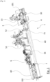
- FIG.1 is a perspective view of a device for processing multiple faces of an object according to one embodiment of the invention, specially adapted for processing the two opposite faces of cards.
- This device is intended to be integrated into a card personalization chain, which may also include, for example, one or more card programming devices.
- this card processing device 1 makes it possible to print both sides of the cards.
- the card processing device 1 comprises a plurality of conveyors which allow a card to be moved from an input position 101 to an output position 102.
- the elements closer to the input position 101 will be considered, in the present description, as “upstream” of the elements closer to the output position 102.
- the elements closer to the output position 102 will be considered “downstream” of the elements located closer to the input position 101.
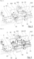
- FIGS. 2 and 3 show in detail the input tray 3, which constitutes the part of the card processing device 1 on which the input position 101 is located.
- the cards can move on this input tray 3 by following a card path 30, in which they are kept on a substantially straight trajectory by lateral borders.
- the input position 101 constitutes a position of the card path 30 located at an edge of the tray 3, the remainder of the card path 30 being located downstream of this input position 101.
- the card path 30 is designed so that the cards move therein in a substantially horizontal position, with one of their faces facing upwards.
- a card 21 is placed in this input position 101. It is brought into this position, for example from another processing equipment, by a lug belt 31, the lugs of which push the cards towards the card path 30. From the input position 101, the lug belt 31 can further push the cards downstream in the card path 30, up to the position in which is located, on the [ Fig.2 ], a card 22.
- the input tray 3 carries a drive fork 32, which can slide along a rail 320 parallel to the card path 30. It is advantageously driven along this rail, in one direction or the other, by a motor, a jack, or any other drive means known to those skilled in the art, which will not be described in more detail.
- This drive fork 32 is also movable, in a vertical direction, between a high position, in which it can move along the rail 320 without coming into contact with the cards placed in the card path 30, and a low position, in which its fingers 321 and 322 come into contact with the front and rear edges of the cards located in the card path 30.
- the drive fork 32 is located at the upstream end of the rail 320, which is closest to the entry position 101.
- This drive fork 32 is in its low position, such that its finger 321 and its finger 322 surround the front and rear edges of the card 22. As long as the drive fork 32 remains in this low position, it can therefore drive the card 22 in translation, by moving along the rail 320.
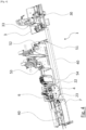
- the [ Fig.3 ] represents the input plate on which the drive fork 32 moved along rail 320 to the downstream end thereof, carrying card 22 along card path 30.
- the drive fork 32 passes the card 22 under a card processing equipment which is, in the embodiment, a plasma processing equipment 33, which projects a plasma beam onto one face of the card to eliminate the surface tension there, and thus improve the adhesion of the ink.
- This plasma processing equipment is capable of processing the face of each card which is facing upwards, here the first face of the card 22.
- the card 22 is brought by the drive fork 32 to the position represented by the [ Fig.3 ], which constitutes the downstream end of the card path 30 on the input tray 3, opposite the input position 101.
- the card 22 is placed in a turning wheel 34 in which a portion of the card path 30 is defined.
- This turning wheel 30 is capable of turning the card 22, by rotating half a turn around a horizontal axis perpendicular to the direction of the card path.
- the card 22 is in the turned-over position, while remaining in the card path 30 and held between the fingers 321 and 322 of the drive fork 32.
- the drive fork 32 can again move downstream, along the rail 320, driving the turned-over card 22, in order to pass this card a second time under the plasma treatment equipment 33. This new passage allows the plasma treatment equipment 33 to treat the second face of the card 22.
- the drive fork 32 brings the card 22 back into the turning wheel 34.
- the turning wheel 34 can again turn the card 22 over, so that its first face is again facing upwards.
- the drive fork 32 moves into a raised position, in which its fingers 321 and 322 no longer surround the edges of the card 22.
- the drive fork 32 moves along the rail 320 without driving the card 22. It can return to the upstream end of the rail 320 to drive a new card, for example the card 21 located immediately downstream of the card 22.
- the drive fork 32 is again moved into its low position, in which the fingers 321 and 322 surround the edges of the card 21.
- the drive fork 32 When the drive fork 32 brings this new card 21 towards the turning wheel 34, its finger 321 pushes out of this turning wheel 34 the card 22 which was previously placed there. The card 22 is thus pushed out of the input tray 3, into a first card location defined on a carriage 4 which is located, at this moment, next to the entry board 3, in the extension of the path of cards 30.
- This movement is identical to that which is represented by the Figures 2 and 3 for card 23, which is in the turning wheel 34 in the position represented by the [ Fig.2 ], and which is pushed by the finger 321 towards the first location 41 of the carriage 4 in the position represented by the [ Fig.3 ].
- the drive fork 32 therefore constitutes a first handling equipment, capable of placing a card in a first location of the carriage, or shuttle 4.
- the carriage 4 also called shuttle 4 is mounted to slide along a rail 40 extending horizontally, parallel to the direction of the card path 30. It is advantageously driven along this rail, in one direction or the other, by a motor, a jack, or any other drive means known to those skilled in the art, which will not be described in more detail.
- This carriage 4 advantageously has two locations 41 and 42, each intended to receive a card in a horizontal position, one of its faces being turned upwards. On this carriage 4, the first location 41 is located upstream of the second location 42.
- the carriage 4 When the drive fork 32 pushes the card 22 out of the tray 3, the carriage 4 is located at the upstream end of the rail 40, so that its first location 41 is placed in the extension of the card path 30 to receive the card pushed by the drive fork 32. At this time, the second location 42 of the carriage 4 is occupied by the card 23, which is placed in this second location in the inverted position, its second face being turned upwards.
- the carriage 4 moves along the rail 40 towards the downstream end thereof. During this movement, the locations 42 and 41, and therefore the cards 23 and 22 placed in these locations, pass successively under processing equipment capable of applying a treatment to the faces of the cards 23 and 22 which are turned upwards.
- an ionizer 51 for eliminating static electricity on the surface of the cards a first printing device 52, a second printing device 53, and an ultraviolet ink drying device 54.
- These devices make it possible to apply the desired treatments to the upward-facing face of the cards that are placed in the locations 41 and 42 of the carriage. In this case, in the embodiment shown, they make it possible to perform two-color printing on the first face of the card 22 and on the second face of the card 23.
- the printing equipments 52 and 53 which are schematically represented on the [ Fig.1 ], constitute the main processing equipment of the processing equipment 1.
- This equipment is advantageously inkjet equipment known per se to those skilled in the art, which projects ink onto the face facing upwards of the cards circulating under the printing equipment.
- Such printing equipment may be monochrome or polychrome.
- the printing equipment 52 and 53 are monochrome, each in a different color, and are placed successively to print in two colors on the face of the cards which is facing upwards.
- These printing equipment are preferably of the type allowing ink drops to be delivered on demand.
- Such equipment is usually designated by the English expression "drop on demand" or by the acronym "DOD”.
- the processing device 1 it is possible to implement, in the processing device 1, other processing equipment. It is possible, for example, for the processing equipment to be laser engraving equipment, for depositing a label on one side of the card, or for varnishing one side of the card.
- these processing equipments are capable of performing the processing continuously, that is to say that they can perform their processing on one side of a card circulating at a constant speed, without there being any need to stop or slow down the carriage ensuring the circulation of the cards to perform the processing.
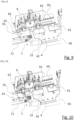
- Fig.4 represents the processing equipment 1 in which the carriage 4 is in its downstream position, after having traveled along the rail 40 to its downstream end, passing the cards 23 and 22 under the processing and printing equipment 51 to 54.
- the card 22 which is in the first location 41 then has its first face, facing upwards and visible in the figure, printed by the printing equipment.
- the card 23 which is in the second location has its second face, facing upwards and visible in the figure, printed by the printing equipment.
- This manipulator 6 When the carriage 4 is in this downstream position, as represented by the figures 5 to 10 , it is located opposite a manipulator 6.
- This manipulator 6 has two clamps 61 and 62 each constituting a handling equipment, and which, in the position of the manipulator 6 represented by the [ Fig.5 ], are respectively opposite the locations 41 and 42 of the carriage 4.
- the clamps 61 and 62 are movable, together, in translation, in a direction perpendicular to the direction of the rail 40, between the position represented by the [ Fig.5 ] in which the clamps 61 and 62 are opposite the locations 41 and 42, and the position represented by the [ Fig.6 ], in which the clamps 61 and 62 are advanced towards the carriage 4 and respectively grasp the cards 22 and 23 placed in the locations 41 and 42.
- the carriage 4 has notches specially designed to allow this advancement of the clamps 61 and 62.
- the clamp 61 grasps the card 22 placed in the slot 41
- the clamp 62 grasps the card 23 placed in slot 42.
- each of these clamps 61 and 62 pivots on itself by half a turn, around a horizontal axis orthogonal to the direction of the rail 40. This pivoting has the effect of turning over the cards held by the clamps 61 and 62.
- the entire manipulator 6 moves, along a rail 60 parallel to the rail 40, until the clamp 61 is located above the location 42, as shown in [ Fig.8 ].
- the clamps 61 and 62 are then moved downwards to the position represented by the [ Fig.9 ], which has the effect of placing the card 22, held by the clamp 61, in the location 42.
- This movement also allows the clamp 62 to deposit the card 23 on a card path 70 of an output tray 7, which is adjacent to the carriage 4 when the latter is in its downstream position.
- a lug belt 71 allows the card 23 to be driven in the card path 70 towards the output position 102, at the downstream end of the plate 7, as shown in [ Fig.10 ]. From this output position 102, the cards can be driven to undergo further processing, to be stored or to be sent.
- the clamps 61 and 62 then perform a horizontal translation movement moving them away from the carriage 4 and the card path 70.
- the clamps 61 and 62 then release the cards they were carrying, which are respectively retained by the edges of the location 42 and the edges of the card path 70.
- the card 22 which was in the first location 41 of the carriage 4 is placed, in the reversed position, in the second location 42 of this carriage, and the card 23 which was in the second location 42 of the carriage 4 is placed, in the reversed position, in the card path 70 of the output tray 7.
- the clamp 61 constitutes handling equipment capable of removing the card placed in the second location 42
- the clamp 62 constitutes handling equipment capable of removing the card placed in the first location 41 and rotating it before placing it in the second location 42.
- the carriage 4 whose first location 41 is now empty, moves back to its upstream position. During this movement, it passes under the equipment 54 to 51, but these equipment preferably do not carry out any treatment.
- This processing equipment then performs its processing, in this case printing, on the upward-facing faces of the cards 21 and 22 contained in the locations 41 and 42.
- this printed face is the second face, opposite the first face which was previously printed.
- the processing equipment therefore prints successively on the second side of the card 22, including the first side which was previously printed, then on a first side of the new card 21.
- the manipulator 6 grasps the card 21 placed in the first location 41 to place it, in the reverse position, in the second location 42, and simultaneously grasps the card 22, both sides of which have been printed, to place it on the card path 70 of the output tray 7.
- the carriage 4 which comprises two slots each capable of holding a card, thus makes it possible to process both sides of the same card using the same printing equipment. By passing the two cards very close to each other under the processing equipment, it makes it possible to obtain a good processing rate. It should also be noted that the processing of the second side of each card is carried out by the processing equipment immediately after the processing of its first side, before the processing of one side of another card.
- the embodiment described above represents a device specially adapted for the treatment of both sides of a card, it is possible to implement the invention for the treatment of any type of objects, having at least two opposite sides or not.
- FIG. 11 to 15 thus represent, schematically, a processing device 8 according to another embodiment, capable of processing several faces of a parallelepiped-shaped object.
- This device comprises an input device 81 and an output device 82.
- a carriage 83, or shuttle 83 can move, along a rail 84, between an upstream position represented by the Figures 11 and 12 and a downstream position represented by the Figures 14 and 15 .
- the trolley 83 has four locations intended to receive identical objects, 91 to 94, in different positions.
- the object 94 is placed on the input equipment 81, and the carriage 83 is in its upstream position, close to the input equipment 81.
- a first handling equipment 85 makes it possible to move the object 94, as schematically represented by the arrow 801, to the first location of the carriage 83, which was previously empty.
- each of the four locations of the carriage 83 contains an object.
- the carriage 83 can then move to its downstream position as schematically represented by the arrow 802.
- it successively passes each of the objects carried in its locations under treatment equipment 86, capable of applying a treatment to the face of the objects 91 to 94 which is turned upwards.
- the carriage then continues its movement, as schematically represented by arrow 803, to its downstream position represented by the [ Fig.14 ].
- the objects 91 to 94 are located under a handling equipment 87.
- This handling equipment 87 is designed to simultaneously handle the objects 91 to 94 placed in the locations of the carriage 83, and move them downstream to the location adjacent to them, while rotating them a quarter turn, as schematically represented by the arrows 804.
- the object 91 is placed on the output equipment 82, the objects 92 to 94 occupy respectively the fourth, third and second locations of the carriage 83, and the first location of the carriage 83 is free.
- This carriage 83 can then move again towards its upstream position, as shown by the arrow 806, to receive a new object in its first location and repeat the steps previously described.
- a carriage prefferably comprises a plurality of locations constituting first locations, intended each for receiving an object from an input device, upstream of the processing trolley, and several locations constituting second locations, each intended to receive an object from a first location, after it has been returned, for example downstream of the processing equipment.
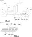
- the [ Fig.16 ] shows a processing device 80 according to another embodiment, capable of processing two faces of objects.
- This device comprises an input device 81 and an output device 82.
- a carriage 830, or shuttle 830, can move along a rail 84, between an upstream position and a downstream position, passing under a processing device 86.
- a first handling equipment 85 makes it possible to place simultaneously on the carriage 830 two objects coming from the input equipment 81, one in the location 831 and the other in the location 832, when this carriage 830 is in its upstream position.
- the locations 831 and 832 are then both first locations.
- the second handling equipment 87 makes it possible to place, in the inverted position, in the location 833 the object which was in the location 831 and in the location 834 the object which was in the location 832.
- the locations 833 and 834 are then both second locations.
- the processing equipment 86 is provided to be able to process the faces of all the objects placed in the locations of the carriage 830, therefore several objects circulating side by side.
- the shuttle comprising several locations is a cart that carries the objects that it moves in front of a processing equipment. It is also possible, in other embodiments, for a shuttle to drive several objects in several locations, without carrying them.
- the [ Fig.17 ] represents a segment of a path 841 that can be used to move objects in front of the processing equipment.
- a fork 88 can move along this path 841. It has three fingers 883, 884 and 885, which can draw the objects that they surround into the path 841.
- the fork 88 thus constitutes a shuttle capable of simultaneously moving two objects, a first object in a first location 882, between the finger 884 and the finger 885, and a second object in a second location 881, between the finger 883 and the finger 884.
Landscapes
- Engineering & Computer Science (AREA)
- Mechanical Engineering (AREA)
- Manufacturing & Machinery (AREA)
- Computer Networks & Wireless Communication (AREA)
- Physics & Mathematics (AREA)
- General Physics & Mathematics (AREA)
- Theoretical Computer Science (AREA)
- Feeding Of Articles By Means Other Than Belts Or Rollers (AREA)
- Sheets, Magazines, And Separation Thereof (AREA)
- Specific Conveyance Elements (AREA)
- Feeding Of Workpieces (AREA)
- Constituent Portions Of Griding Lathes, Driving, Sensing And Control (AREA)
Claims (12)
- Vorrichtung zum Bearbeiten (1, 8, 80) mehrerer Objektflächen, umfassend mindestens eine Bearbeitungseinrichtung (51, 52, 53, 54, 86), die geeignet ist, um eine Bearbeitung auf einer Fläche eines Objekts (21, 22, 23, 91, 92, 93, 94) auszuführen, die gegenüber der Verarbeitungseinrichtung vorgewiesen wird;
dadurch gekennzeichnet, dass sie auch umfasst:- ein Shuttle (4, 83, 88), der mindestens zwei Stellen (41, 42, 831, 832, 833, 834) aufweist, die zum Aufnehmen von Objekten angepasst sind, wobei der Shuttle zwischen einer ersten Position und einer zweiten Position bewegbar montiert ist, indem er Zwischenpositionen passiert, in denen er eine Fläche von Objekten vorweist, die an den Stellen gegenüber der oder den Verarbeitungseinrichtung(en) platziert sind;- eine erste Handhabungseinrichtung (32, 85), die geeignet ist, um ein Objekt an einer ersten der Stellen (41) zu platzieren, wenn der Shuttle in der ersten Position ist;- eine zweite Handhabungseinrichtung (62), die geeignet ist, um ein Objekt zu entfernen, das an der zweiten der Stellen (42) platziert ist; und- eine dritte Handhabungseinrichtung (61), die geeignet ist, um ein Objekt zu entfernen, das an der ersten Stelle (41) platziert ist, und es zu drehen, bevor es an der zweiten Stelle (42) platziert wird. - Vorrichtung zum Bearbeiten mehrerer Objektflächen nach dem vorstehenden Anspruch, dadurch gekennzeichnet, dass die dritte Handhabungseinrichtung (61) platziert ist, um die Objekte zu handhaben, die durch den Shuttle getragen werden, wenn der Shuttle in der zweiten Position ist.
- Vorrichtung zum Bearbeiten mehrerer Objektflächen nach einem der vorstehenden Ansprüche, dadurch gekennzeichnet, dass die zweite Handhabungseinrichtung (62) platziert ist, um die Objekte zu handhaben, die durch den Shuttle getragen werden, wenn der Shuttle in der zweiten Position ist.
- Vorrichtung zum Bearbeiten mehrerer Objektflächen nach einem der vorstehenden Ansprüche, dadurch gekennzeichnet, dass die Verarbeitungseinrichtung(en) mindestens einen Drucker (52, 53) umfassen, der geeignet ist, um eine Fläche eines Objekts zu bedrucken.
- Vorrichtung zum Bearbeiten mehrerer Objektflächen nach dem vorstehenden Anspruch, dadurch gekennzeichnet, dass der Drucker ein "Drop-on-Demand"-Drucker ist.
- Vorrichtung zum Bearbeiten mehrerer Objektflächen nach einem der vorstehenden Ansprüche, dadurch gekennzeichnet, dass die Stellen (41, 42) relativ zu dem Shuttle angeordnet sind, um bei der Bewegung des Shuttles (4, 83, 88) zwischen der ersten Position und der zweiten Position nacheinander gegenüber der oder den Bearbeitungseinrichtungen (51, 52, 53, 54, 86) zu passieren.
- Vorrichtung zum Bearbeiten mehrerer Objektflächen nach dem vorstehenden Anspruch, dadurch gekennzeichnet, dass die Stellen (41, 42) relativ zu dem Shuttle so angeordnet sind, dass die zweite Stelle (42) bei der Bewegung des Shuttles von der ersten Position in die zweite Position vor der ersten Stelle (41) gegenüber der oder den Verarbeitungseinrichtung(en) (51, 52, 53, 54, 86) passiert.
- Vorrichtung zum Bearbeiten mehrerer Objektflächen nach einem der vorstehenden Ansprüche, dadurch gekennzeichnet, dass die erste und die zweite Stelle jeweils geeignet sind, um ein flaches Objekt aufzunehmen, das in einer im Wesentlichen horizontalen Position platziert ist, wobei die obere Fläche des Objekts sichtbar bleibt.
- Vorrichtung zum Bearbeiten mehrerer Objektflächen nach einem der vorstehenden Ansprüche, dadurch gekennzeichnet, dass der Shuttle (4, 83) zwischen der ersten Position und der zweiten Position entlang mindestens einer Führungsschiene (40, 84) translatorisch bewegbar ist.
- Vorrichtung zum Bearbeiten mehrerer Objektflächen nach einem der vorstehenden Ansprüche, dadurch gekennzeichnet, dass sie ein Handhabungsgerät (6) umfasst, umfassend einen Greifer (62), der die zweite Handhabungseinrichtung ausbildet, und einen Greifer (61), der die dritte Manipulationseinrichtung ausbildet.
- Vorrichtung zum Bearbeiten mehrerer Objektflächen nach einem der vorstehenden Ansprüche, dadurch gekennzeichnet, dass der Shuttle (4, 83) ein Wagen ist, in dem die Stellen definiert sind, wobei der Wagen geeignet ist, um die Objekte zu tragen, die an den Stellen platziert werden.
- Verfahren zum Bearbeiten mehrerer Objektflächen (21, 22, 23, 91, 92, 93, 94), umfassend- einen Schritt zum Platzieren eines ersten Objekts an einer ersten Stelle (41, 831, 832, 882), die in einem Shuttle (4, 83, 88) vorgesehen ist, wobei der Shuttle eine zweite Stelle (42, 833, 834, 881) vorweist, umfassend ein zweites Objekt;- einen Schritt zum Bewegen des Shuttles (4, 83, 88) entlang einer Bahn, in deren Verlauf eine Fläche jedes der ersten und des zweiten Objekts gegenüber einer Bearbeitungseinrichtung (51, 52, 53, 54, 86) passiert, die geeignet ist, um eine Bearbeitung der Fläche auszuführen;- einen Schritt zum Entladen des zweiten Objekts von der zweiten Stelle (42, 833, 834, 881),- einen Schritt zum Entladen des ersten Objekts von der ersten Stelle (41, 831, 832, 882), zum Umdrehen des ersten Objekts und zum Platzieren des ersten Objekts in umgedrehter Position an der zweiten Stelle (42, 833, 834, 881).
Applications Claiming Priority (2)
| Application Number | Priority Date | Filing Date | Title |
|---|---|---|---|
| FR1913259A FR3103404B1 (fr) | 2019-11-26 | 2019-11-26 | Dispositif de traitement de plusieurs faces d’objets, et procédé de traitement correspondant |
| PCT/IB2020/061168 WO2021105913A1 (fr) | 2019-11-26 | 2020-11-26 | Dispositif de traitement de plusieurs faces d'objets, et procédé de traitement correspondant |
Publications (3)
| Publication Number | Publication Date |
|---|---|
| EP4065377A1 EP4065377A1 (de) | 2022-10-05 |
| EP4065377C0 EP4065377C0 (de) | 2025-02-12 |
| EP4065377B1 true EP4065377B1 (de) | 2025-02-12 |
Family
ID=69700092
Family Applications (1)
| Application Number | Title | Priority Date | Filing Date |
|---|---|---|---|
| EP20815954.1A Active EP4065377B1 (de) | 2019-11-26 | 2020-11-26 | Vorrichtung zur behandlung von mehreren oberflächen von gegenständen und entsprechendes behandlungsverfahren |
Country Status (4)
| Country | Link |
|---|---|
| US (1) | US12049377B2 (de) |
| EP (1) | EP4065377B1 (de) |
| FR (1) | FR3103404B1 (de) |
| WO (1) | WO2021105913A1 (de) |
Families Citing this family (5)
| Publication number | Priority date | Publication date | Assignee | Title |
|---|---|---|---|---|
| EP4319985A4 (de) * | 2021-04-05 | 2025-03-05 | Entrust Corporation | Drucken von identifikationsdokumenten auf abruf mit verbesserter druckhaftung |
| US11858257B2 (en) * | 2021-07-16 | 2024-01-02 | Entrust Corporation | Cure lamp shutter |
| CN114714775B (zh) * | 2022-04-13 | 2023-03-31 | 苏州宇信特殊包装股份有限公司 | 一种瓦楞纸箱后加工用喷码装置 |
| IT202200024579A1 (it) * | 2022-11-29 | 2024-05-29 | Atlantic Zeiser Gmbh | Metodo e impianto per la stampa di carte |
| DE102024104575A1 (de) | 2024-02-19 | 2025-08-21 | Mb Automation Gmbh & Co. Kg | Verfahren und Vorrichtung zum ein- oder beidseitigen Bedrucken von Druck-Medien |
Citations (2)
| Publication number | Priority date | Publication date | Assignee | Title |
|---|---|---|---|---|
| AU2007201457A1 (en) * | 2006-05-17 | 2007-12-06 | Werner Kammann Maschinenfabrik Gmbh & Co. Kg | Apparatus for decorating objects |
| EP1705600B1 (de) * | 2005-03-23 | 2010-07-21 | Datacard Corporation | Lasermarkiermaschine mit großer Geschwindigkeit |
Family Cites Families (7)
| Publication number | Priority date | Publication date | Assignee | Title |
|---|---|---|---|---|
| FR2827807B1 (fr) * | 2001-07-27 | 2003-10-10 | Leroux Gilles Sa | Dispositif modulaire d'impression graphique couleur de cartes |
| FR2898528B1 (fr) * | 2006-03-14 | 2008-05-30 | Datacard Corp | Machine de marquage laser a haute cadence |
| JP5096718B2 (ja) * | 2006-09-26 | 2012-12-12 | 新田電材株式会社 | タグ印刷装置及び同装置用ジグ |
| US8690283B2 (en) * | 2009-10-20 | 2014-04-08 | Sandisk Il Ltd. | Method and system for printing graphical content onto a plurality of memory devices and for providing a visually distinguishable memory device |
| WO2011101701A1 (en) * | 2010-02-22 | 2011-08-25 | Datacard Corporation | Method of and apparatus for personalising a portable object |
| CN110603152A (zh) * | 2017-05-09 | 2019-12-20 | 恩图鲁斯特咨询卡有限公司 | 卡加工系统中的双卡输送 |
| CN110126463B (zh) * | 2019-05-31 | 2020-12-25 | 沈阳友联电子装备有限公司 | 单套dod式喷码机的双面喷码方法及装置 |
-
2019
- 2019-11-26 FR FR1913259A patent/FR3103404B1/fr active Active
-
2020
- 2020-11-26 EP EP20815954.1A patent/EP4065377B1/de active Active
- 2020-11-26 US US17/779,178 patent/US12049377B2/en active Active
- 2020-11-26 WO PCT/IB2020/061168 patent/WO2021105913A1/fr not_active Ceased
Patent Citations (2)
| Publication number | Priority date | Publication date | Assignee | Title |
|---|---|---|---|---|
| EP1705600B1 (de) * | 2005-03-23 | 2010-07-21 | Datacard Corporation | Lasermarkiermaschine mit großer Geschwindigkeit |
| AU2007201457A1 (en) * | 2006-05-17 | 2007-12-06 | Werner Kammann Maschinenfabrik Gmbh & Co. Kg | Apparatus for decorating objects |
Also Published As
| Publication number | Publication date |
|---|---|
| US20220402714A1 (en) | 2022-12-22 |
| EP4065377A1 (de) | 2022-10-05 |
| US12049377B2 (en) | 2024-07-30 |
| WO2021105913A1 (fr) | 2021-06-03 |
| EP4065377C0 (de) | 2025-02-12 |
| FR3103404B1 (fr) | 2024-02-23 |
| FR3103404A1 (fr) | 2021-05-28 |
Similar Documents
| Publication | Publication Date | Title |
|---|---|---|
| EP4065377B1 (de) | Vorrichtung zur behandlung von mehreren oberflächen von gegenständen und entsprechendes behandlungsverfahren | |
| EP3292043B1 (de) | Maschine mit einer vorrichtung für chargenverpackung mit geregelter zufuhr und dem entsprechenden zuführverfahren | |
| EP2391566A1 (de) | Vorrichtung zur positionierung eines plattenelements in einer einsetzstation einer verarbeitungsmaschine | |
| EP2838733B1 (de) | Vorrichtung und verfahren zum transportieren von substraten in einer druckmaschine | |
| EP1666386A1 (de) | Vorrichtung und Verfahren zum Ausrichten von flachen Gegenständen | |
| EP1280667A1 (de) | Vorrichtung zum behandeln von bedruckten bogen | |
| EP2976279B1 (de) | Vorrichtung zum ausstossen eines flachen gegenstandes während der förderung | |
| FR2520298A1 (fr) | Dispositif pour la fabrication de blocs encolles au dos | |
| EP0379447B1 (de) | Flexible Tampondruckmaschine | |
| EP0514340A1 (de) | Verfahren und Vorrichtung zum Vorbereiten von Verpackungszuschnitten | |
| FR3068644A1 (fr) | Ensemble de mise a niveau d'unite de support pour des dispositifs de traitement de support | |
| FR3073172A1 (fr) | Tremie de sortie pour dispositifs de traitement de support | |
| FR2605614A1 (fr) | Distributeur de billets de banque d'une machine destinee a recevoir et distribuer des billets | |
| FR2997039A1 (fr) | Machine a imprimer par jets d'encre a lunette de calibrage | |
| CH692575A5 (fr) | Imprimante recto -verso. | |
| FR2694268A1 (fr) | Dispositif d'application d'étiquettes pour étiqueter automatiquement des articles. | |
| FR3007742B1 (fr) | Procede et dispositif de conditionnement de composants non rigides | |
| EP0012887A2 (de) | Vertikales und horizontales Schreiben erlaubender Tintenstrahldrucker | |
| FR2676941A1 (fr) | Module de case pour machine de tri. | |
| FR2652802A1 (fr) | Dispositif de transport pour plaques, en particulier a surface sensible. | |
| FR2881935A1 (fr) | Distributeur automatique de produits | |
| EP0059674A1 (de) | Siebdruckvorrichtung für Flakons oder dgl. | |
| FR2526710A1 (fr) | Machine d'impression comportant un transporteur d'objets a une seule chaine | |
| FR3107886A1 (fr) | Dispositif d'emballage et procédé destiné à faire fonctionner un dispositif d'emballage | |
| EP3529186B1 (de) | Vorrichtung und verfahren zur weichenstellung und zum auswurf von zuschnitten |
Legal Events
| Date | Code | Title | Description |
|---|---|---|---|
| STAA | Information on the status of an ep patent application or granted ep patent |
Free format text: STATUS: UNKNOWN |
|
| STAA | Information on the status of an ep patent application or granted ep patent |
Free format text: STATUS: THE INTERNATIONAL PUBLICATION HAS BEEN MADE |
|
| PUAI | Public reference made under article 153(3) epc to a published international application that has entered the european phase |
Free format text: ORIGINAL CODE: 0009012 |
|
| STAA | Information on the status of an ep patent application or granted ep patent |
Free format text: STATUS: REQUEST FOR EXAMINATION WAS MADE |
|
| 17P | Request for examination filed |
Effective date: 20220617 |
|
| AK | Designated contracting states |
Kind code of ref document: A1 Designated state(s): AL AT BE BG CH CY CZ DE DK EE ES FI FR GB GR HR HU IE IS IT LI LT LU LV MC MK MT NL NO PL PT RO RS SE SI SK SM TR |
|
| DAV | Request for validation of the european patent (deleted) | ||
| DAX | Request for extension of the european patent (deleted) | ||
| GRAP | Despatch of communication of intention to grant a patent |
Free format text: ORIGINAL CODE: EPIDOSNIGR1 |
|
| STAA | Information on the status of an ep patent application or granted ep patent |
Free format text: STATUS: GRANT OF PATENT IS INTENDED |
|
| RIC1 | Information provided on ipc code assigned before grant |
Ipc: B41J 11/00 20060101ALN20240912BHEP Ipc: B41J 3/407 20060101ALN20240912BHEP Ipc: B41J 13/12 20060101ALI20240912BHEP Ipc: B65H 5/04 20060101ALI20240912BHEP Ipc: B65H 15/00 20060101ALI20240912BHEP Ipc: G06K 13/07 20060101ALI20240912BHEP Ipc: G06K 19/077 20060101ALI20240912BHEP Ipc: B65G 47/248 20060101ALI20240912BHEP Ipc: B41J 3/60 20060101AFI20240912BHEP |
|
| INTG | Intention to grant announced |
Effective date: 20240930 |
|
| GRAS | Grant fee paid |
Free format text: ORIGINAL CODE: EPIDOSNIGR3 |
|
| GRAA | (expected) grant |
Free format text: ORIGINAL CODE: 0009210 |
|
| STAA | Information on the status of an ep patent application or granted ep patent |
Free format text: STATUS: THE PATENT HAS BEEN GRANTED |
|
| AK | Designated contracting states |
Kind code of ref document: B1 Designated state(s): AL AT BE BG CH CY CZ DE DK EE ES FI FR GB GR HR HU IE IS IT LI LT LU LV MC MK MT NL NO PL PT RO RS SE SI SK SM TR |
|
| REG | Reference to a national code |
Ref country code: GB Ref legal event code: FG4D Free format text: NOT ENGLISH |
|
| REG | Reference to a national code |
Ref country code: CH Ref legal event code: EP |
|
| REG | Reference to a national code |
Ref country code: DE Ref legal event code: R096 Ref document number: 602020046018 Country of ref document: DE |
|
| REG | Reference to a national code |
Ref country code: IE Ref legal event code: FG4D Free format text: LANGUAGE OF EP DOCUMENT: FRENCH |
|
| U01 | Request for unitary effect filed |
Effective date: 20250307 |
|
| U07 | Unitary effect registered |
Designated state(s): AT BE BG DE DK EE FI FR IT LT LU LV MT NL PT RO SE SI Effective date: 20250320 |
|
| PG25 | Lapsed in a contracting state [announced via postgrant information from national office to epo] |
Ref country code: RS Free format text: LAPSE BECAUSE OF FAILURE TO SUBMIT A TRANSLATION OF THE DESCRIPTION OR TO PAY THE FEE WITHIN THE PRESCRIBED TIME-LIMIT Effective date: 20250512 |
|
| PG25 | Lapsed in a contracting state [announced via postgrant information from national office to epo] |
Ref country code: PL Free format text: LAPSE BECAUSE OF FAILURE TO SUBMIT A TRANSLATION OF THE DESCRIPTION OR TO PAY THE FEE WITHIN THE PRESCRIBED TIME-LIMIT Effective date: 20250212 |
|
| PG25 | Lapsed in a contracting state [announced via postgrant information from national office to epo] |
Ref country code: ES Free format text: LAPSE BECAUSE OF FAILURE TO SUBMIT A TRANSLATION OF THE DESCRIPTION OR TO PAY THE FEE WITHIN THE PRESCRIBED TIME-LIMIT Effective date: 20250212 |
|
| PG25 | Lapsed in a contracting state [announced via postgrant information from national office to epo] |
Ref country code: IS Free format text: LAPSE BECAUSE OF FAILURE TO SUBMIT A TRANSLATION OF THE DESCRIPTION OR TO PAY THE FEE WITHIN THE PRESCRIBED TIME-LIMIT Effective date: 20250612 Ref country code: NO Free format text: LAPSE BECAUSE OF FAILURE TO SUBMIT A TRANSLATION OF THE DESCRIPTION OR TO PAY THE FEE WITHIN THE PRESCRIBED TIME-LIMIT Effective date: 20250512 |
|
| PG25 | Lapsed in a contracting state [announced via postgrant information from national office to epo] |
Ref country code: HR Free format text: LAPSE BECAUSE OF FAILURE TO SUBMIT A TRANSLATION OF THE DESCRIPTION OR TO PAY THE FEE WITHIN THE PRESCRIBED TIME-LIMIT Effective date: 20250212 |
|
| PG25 | Lapsed in a contracting state [announced via postgrant information from national office to epo] |
Ref country code: GR Free format text: LAPSE BECAUSE OF FAILURE TO SUBMIT A TRANSLATION OF THE DESCRIPTION OR TO PAY THE FEE WITHIN THE PRESCRIBED TIME-LIMIT Effective date: 20250513 |
|
| PG25 | Lapsed in a contracting state [announced via postgrant information from national office to epo] |
Ref country code: SM Free format text: LAPSE BECAUSE OF FAILURE TO SUBMIT A TRANSLATION OF THE DESCRIPTION OR TO PAY THE FEE WITHIN THE PRESCRIBED TIME-LIMIT Effective date: 20250212 |
|
| PG25 | Lapsed in a contracting state [announced via postgrant information from national office to epo] |
Ref country code: CZ Free format text: LAPSE BECAUSE OF FAILURE TO SUBMIT A TRANSLATION OF THE DESCRIPTION OR TO PAY THE FEE WITHIN THE PRESCRIBED TIME-LIMIT Effective date: 20250212 |
|
| PG25 | Lapsed in a contracting state [announced via postgrant information from national office to epo] |
Ref country code: SK Free format text: LAPSE BECAUSE OF FAILURE TO SUBMIT A TRANSLATION OF THE DESCRIPTION OR TO PAY THE FEE WITHIN THE PRESCRIBED TIME-LIMIT Effective date: 20250212 |