EP4065347B1 - Hochgeschwindigkeits-3d-laserdrucksystem - Google Patents
Hochgeschwindigkeits-3d-laserdrucksystem Download PDFInfo
- Publication number
- EP4065347B1 EP4065347B1 EP20893859.7A EP20893859A EP4065347B1 EP 4065347 B1 EP4065347 B1 EP 4065347B1 EP 20893859 A EP20893859 A EP 20893859A EP 4065347 B1 EP4065347 B1 EP 4065347B1
- Authority
- EP
- European Patent Office
- Prior art keywords
- laser
- electromagnetic radiation
- image
- substrate
- images
- Prior art date
- Legal status (The legal status is an assumption and is not a legal conclusion. Google has not performed a legal analysis and makes no representation as to the accuracy of the status listed.)
- Active
Links
Images


Classifications
-
- C—CHEMISTRY; METALLURGY
- C23—COATING METALLIC MATERIAL; COATING MATERIAL WITH METALLIC MATERIAL; CHEMICAL SURFACE TREATMENT; DIFFUSION TREATMENT OF METALLIC MATERIAL; COATING BY VACUUM EVAPORATION, BY SPUTTERING, BY ION IMPLANTATION OR BY CHEMICAL VAPOUR DEPOSITION, IN GENERAL; INHIBITING CORROSION OF METALLIC MATERIAL OR INCRUSTATION IN GENERAL
- C23C—COATING METALLIC MATERIAL; COATING MATERIAL WITH METALLIC MATERIAL; SURFACE TREATMENT OF METALLIC MATERIAL BY DIFFUSION INTO THE SURFACE, BY CHEMICAL CONVERSION OR SUBSTITUTION; COATING BY VACUUM EVAPORATION, BY SPUTTERING, BY ION IMPLANTATION OR BY CHEMICAL VAPOUR DEPOSITION, IN GENERAL
- C23C24/00—Coating starting from inorganic powder
- C23C24/08—Coating starting from inorganic powder by application of heat or pressure and heat
-
- B—PERFORMING OPERATIONS; TRANSPORTING
- B29—WORKING OF PLASTICS; WORKING OF SUBSTANCES IN A PLASTIC STATE IN GENERAL
- B29C—SHAPING OR JOINING OF PLASTICS; SHAPING OF MATERIAL IN A PLASTIC STATE, NOT OTHERWISE PROVIDED FOR; AFTER-TREATMENT OF THE SHAPED PRODUCTS, e.g. REPAIRING
- B29C64/00—Additive manufacturing, i.e. manufacturing of three-dimensional [3D] objects by additive deposition, additive agglomeration or additive layering, e.g. by 3D printing, stereolithography or selective laser sintering
- B29C64/20—Apparatus for additive manufacturing; Details thereof or accessories therefor
- B29C64/264—Arrangements for irradiation
- B29C64/268—Arrangements for irradiation using laser beams; using electron beams [EB]
-
- B—PERFORMING OPERATIONS; TRANSPORTING
- B22—CASTING; POWDER METALLURGY
- B22F—WORKING METALLIC POWDER; MANUFACTURE OF ARTICLES FROM METALLIC POWDER; MAKING METALLIC POWDER; APPARATUS OR DEVICES SPECIALLY ADAPTED FOR METALLIC POWDER
- B22F1/00—Metallic powder; Treatment of metallic powder, e.g. to facilitate working or to improve properties
- B22F1/16—Metallic particles coated with a non-metal
-
- B—PERFORMING OPERATIONS; TRANSPORTING
- B29—WORKING OF PLASTICS; WORKING OF SUBSTANCES IN A PLASTIC STATE IN GENERAL
- B29C—SHAPING OR JOINING OF PLASTICS; SHAPING OF MATERIAL IN A PLASTIC STATE, NOT OTHERWISE PROVIDED FOR; AFTER-TREATMENT OF THE SHAPED PRODUCTS, e.g. REPAIRING
- B29C64/00—Additive manufacturing, i.e. manufacturing of three-dimensional [3D] objects by additive deposition, additive agglomeration or additive layering, e.g. by 3D printing, stereolithography or selective laser sintering
- B29C64/10—Processes of additive manufacturing
- B29C64/141—Processes of additive manufacturing using only solid materials
- B29C64/153—Processes of additive manufacturing using only solid materials using layers of powder being selectively joined, e.g. by selective laser sintering or melting
-
- B—PERFORMING OPERATIONS; TRANSPORTING
- B29—WORKING OF PLASTICS; WORKING OF SUBSTANCES IN A PLASTIC STATE IN GENERAL
- B29C—SHAPING OR JOINING OF PLASTICS; SHAPING OF MATERIAL IN A PLASTIC STATE, NOT OTHERWISE PROVIDED FOR; AFTER-TREATMENT OF THE SHAPED PRODUCTS, e.g. REPAIRING
- B29C64/00—Additive manufacturing, i.e. manufacturing of three-dimensional [3D] objects by additive deposition, additive agglomeration or additive layering, e.g. by 3D printing, stereolithography or selective laser sintering
- B29C64/20—Apparatus for additive manufacturing; Details thereof or accessories therefor
- B29C64/227—Driving means
- B29C64/232—Driving means for motion along the axis orthogonal to the plane of a layer
-
- B—PERFORMING OPERATIONS; TRANSPORTING
- B29—WORKING OF PLASTICS; WORKING OF SUBSTANCES IN A PLASTIC STATE IN GENERAL
- B29C—SHAPING OR JOINING OF PLASTICS; SHAPING OF MATERIAL IN A PLASTIC STATE, NOT OTHERWISE PROVIDED FOR; AFTER-TREATMENT OF THE SHAPED PRODUCTS, e.g. REPAIRING
- B29C64/00—Additive manufacturing, i.e. manufacturing of three-dimensional [3D] objects by additive deposition, additive agglomeration or additive layering, e.g. by 3D printing, stereolithography or selective laser sintering
- B29C64/20—Apparatus for additive manufacturing; Details thereof or accessories therefor
- B29C64/227—Driving means
- B29C64/236—Driving means for motion in a direction within the plane of a layer
-
- B—PERFORMING OPERATIONS; TRANSPORTING
- B29—WORKING OF PLASTICS; WORKING OF SUBSTANCES IN A PLASTIC STATE IN GENERAL
- B29C—SHAPING OR JOINING OF PLASTICS; SHAPING OF MATERIAL IN A PLASTIC STATE, NOT OTHERWISE PROVIDED FOR; AFTER-TREATMENT OF THE SHAPED PRODUCTS, e.g. REPAIRING
- B29C64/00—Additive manufacturing, i.e. manufacturing of three-dimensional [3D] objects by additive deposition, additive agglomeration or additive layering, e.g. by 3D printing, stereolithography or selective laser sintering
- B29C64/20—Apparatus for additive manufacturing; Details thereof or accessories therefor
- B29C64/245—Platforms or substrates
-
- B—PERFORMING OPERATIONS; TRANSPORTING
- B29—WORKING OF PLASTICS; WORKING OF SUBSTANCES IN A PLASTIC STATE IN GENERAL
- B29C—SHAPING OR JOINING OF PLASTICS; SHAPING OF MATERIAL IN A PLASTIC STATE, NOT OTHERWISE PROVIDED FOR; AFTER-TREATMENT OF THE SHAPED PRODUCTS, e.g. REPAIRING
- B29C64/00—Additive manufacturing, i.e. manufacturing of three-dimensional [3D] objects by additive deposition, additive agglomeration or additive layering, e.g. by 3D printing, stereolithography or selective laser sintering
- B29C64/20—Apparatus for additive manufacturing; Details thereof or accessories therefor
- B29C64/264—Arrangements for irradiation
- B29C64/277—Arrangements for irradiation using multiple radiation means, e.g. micromirrors or multiple light-emitting diodes [LED]
-
- B—PERFORMING OPERATIONS; TRANSPORTING
- B29—WORKING OF PLASTICS; WORKING OF SUBSTANCES IN A PLASTIC STATE IN GENERAL
- B29C—SHAPING OR JOINING OF PLASTICS; SHAPING OF MATERIAL IN A PLASTIC STATE, NOT OTHERWISE PROVIDED FOR; AFTER-TREATMENT OF THE SHAPED PRODUCTS, e.g. REPAIRING
- B29C64/00—Additive manufacturing, i.e. manufacturing of three-dimensional [3D] objects by additive deposition, additive agglomeration or additive layering, e.g. by 3D printing, stereolithography or selective laser sintering
- B29C64/20—Apparatus for additive manufacturing; Details thereof or accessories therefor
- B29C64/264—Arrangements for irradiation
- B29C64/286—Optical filters, e.g. masks
-
- B—PERFORMING OPERATIONS; TRANSPORTING
- B29—WORKING OF PLASTICS; WORKING OF SUBSTANCES IN A PLASTIC STATE IN GENERAL
- B29C—SHAPING OR JOINING OF PLASTICS; SHAPING OF MATERIAL IN A PLASTIC STATE, NOT OTHERWISE PROVIDED FOR; AFTER-TREATMENT OF THE SHAPED PRODUCTS, e.g. REPAIRING
- B29C64/00—Additive manufacturing, i.e. manufacturing of three-dimensional [3D] objects by additive deposition, additive agglomeration or additive layering, e.g. by 3D printing, stereolithography or selective laser sintering
- B29C64/30—Auxiliary operations or equipment
- B29C64/386—Data acquisition or data processing for additive manufacturing
- B29C64/393—Data acquisition or data processing for additive manufacturing for controlling or regulating additive manufacturing processes
-
- B—PERFORMING OPERATIONS; TRANSPORTING
- B41—PRINTING; LINING MACHINES; TYPEWRITERS; STAMPS
- B41J—TYPEWRITERS; SELECTIVE PRINTING MECHANISMS, i.e. MECHANISMS PRINTING OTHERWISE THAN FROM A FORME; CORRECTION OF TYPOGRAPHICAL ERRORS
- B41J2/00—Typewriters or selective printing mechanisms characterised by the printing or marking process for which they are designed
- B41J2/435—Typewriters or selective printing mechanisms characterised by the printing or marking process for which they are designed characterised by selective application of radiation to a printing material or impression-transfer material
- B41J2/475—Typewriters or selective printing mechanisms characterised by the printing or marking process for which they are designed characterised by selective application of radiation to a printing material or impression-transfer material for heating selectively by radiation or ultrasonic waves
-
- B—PERFORMING OPERATIONS; TRANSPORTING
- B33—ADDITIVE MANUFACTURING TECHNOLOGY
- B33Y—ADDITIVE MANUFACTURING, i.e. MANUFACTURING OF THREE-DIMENSIONAL [3-D] OBJECTS BY ADDITIVE DEPOSITION, ADDITIVE AGGLOMERATION OR ADDITIVE LAYERING, e.g. BY 3-D PRINTING, STEREOLITHOGRAPHY OR SELECTIVE LASER SINTERING
- B33Y10/00—Processes of additive manufacturing
-
- B—PERFORMING OPERATIONS; TRANSPORTING
- B33—ADDITIVE MANUFACTURING TECHNOLOGY
- B33Y—ADDITIVE MANUFACTURING, i.e. MANUFACTURING OF THREE-DIMENSIONAL [3-D] OBJECTS BY ADDITIVE DEPOSITION, ADDITIVE AGGLOMERATION OR ADDITIVE LAYERING, e.g. BY 3-D PRINTING, STEREOLITHOGRAPHY OR SELECTIVE LASER SINTERING
- B33Y30/00—Apparatus for additive manufacturing; Details thereof or accessories therefor
-
- B—PERFORMING OPERATIONS; TRANSPORTING
- B33—ADDITIVE MANUFACTURING TECHNOLOGY
- B33Y—ADDITIVE MANUFACTURING, i.e. MANUFACTURING OF THREE-DIMENSIONAL [3-D] OBJECTS BY ADDITIVE DEPOSITION, ADDITIVE AGGLOMERATION OR ADDITIVE LAYERING, e.g. BY 3-D PRINTING, STEREOLITHOGRAPHY OR SELECTIVE LASER SINTERING
- B33Y50/00—Data acquisition or data processing for additive manufacturing
- B33Y50/02—Data acquisition or data processing for additive manufacturing for controlling or regulating additive manufacturing processes
-
- B—PERFORMING OPERATIONS; TRANSPORTING
- B41—PRINTING; LINING MACHINES; TYPEWRITERS; STAMPS
- B41J—TYPEWRITERS; SELECTIVE PRINTING MECHANISMS, i.e. MECHANISMS PRINTING OTHERWISE THAN FROM A FORME; CORRECTION OF TYPOGRAPHICAL ERRORS
- B41J3/00—Typewriters or selective printing or marking mechanisms characterised by the purpose for which they are constructed
- B41J3/407—Typewriters or selective printing or marking mechanisms characterised by the purpose for which they are constructed for marking on special material
- B41J3/4073—Printing on three-dimensional objects not being in sheet or web form, e.g. spherical or cubic objects
Definitions
- the invention relates to printing system.
- the invention relates to systems for applying durable colorfast coatings over large and topographically sophisticated structures.
- Printing systems and laser engravers used to form images on three-dimensional objects have been produced by several manufacturers. Typically, these systems require a methodology for manipulating the beam over the targeted surface. Often the beam targeting and manipulation is accomplished with reflective optics and in some cases with transmissive spatial light modulators. Various optical components are utilized to position the beam on the target surface uniformly to maintain a consistent beam footprint.
- the original data to be printed is typically represented in a human readable form. This information is then scaled or dimensionally altered whereby the image elements are scaled proportionally on the desired surface for which it is to be printed.
- EP 2 641 661 A1 discloses a graphical application system with a surface spattering device, a spatial referencing unit, a computation means and a commuication means.
- the spatial referencing unit is located remote from the spattering device and comprises a 3D imaging unit with at least two optical 2D cameras arranged with a stereobasis inbetween the cameras, the 3 D imaging unit being designed for determining the position and orientation of the spattering device by digital image processing of images taken by the cameras.
- the aforementioned visible laser beam which is coaxially aligned with the application laser is utilized in conjunction with the higher powered "application laser".
- This laser can then be scanned over the surface that is designated for the image application.
- An additional visible laser can then be used to represent the selected image and its defined area.
- This imaging laser is further used to scale and position the subdivided described in this text. This image that conforms to the end-user requirements on the target surface.
- a common method used to represent and position an image on a target surface is by use of a raster scan generator or otherwise a scalable projection device.
- the raster scanned beam is scanned across the surface typically from the left to right and top to bottom.
- the same visible laser system can also be vectored, whereby the laser is directed over the entirety of the target surface using coordinates where the laser begins and where it stops. During this process the laser beam can be turned on or off as directed by the laser control program.
- a further problem associated with using both inks and paints is that in order to decrease bleed over and to obtain the correct color rendition these coatings would have to be applied through a jetting process. This is much the same way inkjets are used on color printers. This is a very difficult technique when used in conjunction with thick pigments that are normally found in paints. Additionally, the majority of these types of "jetted" coatings often do not have the properties required for an outdoor environment. Anybody who has used these types inks and coatings before are familiar with the fact that they fade rather rapidly in intense UV light. Further to this these types of pigments degrade rapidly in harsh environments due to the fact that these coatings are often very thin when applied. These environments often include corrosive elements such as acid rain, Ozone, and very fine particle precipitants.
- the present invention attempts to eliminate many of these problems and allow a person of average skill to apply high quality graphics and images through etching or DLI (direct laser illustrating).
- a primary objective of this invention is to provide a means for applying digital or graphic images in durable colorfast coatings over large and topographically sophisticated structures.
- the present invention allows a person of average skill to apply high quality graphics and images through etching or DLI (direct laser illustrating).
- the immediate invention in question uses direct laser illustrating that forms an image through a plurality of pigmented PELs (Picture Elements) combined together and dithered to produce a completed image. This is very similar to the way poster images have been constructed for decades.
- Direct laser illustration is not only limited to dithering to form the color images, additional techniques can be easily employed. Any user defined illustration space may be constructed. Techniques such as with additive color mixing and dithering that utilize translucent pigments may also be utilized as well in conjunction with grayscale image formulation and other techniques.
- the system includes an operational curing system comprised of a thermal acquisition system, a distance monitoring device, and a directed radiant energy source.
- the system also includes a support assembly for supporting the operational curing system relative to a substrate and a computer-based control system processing data and controlling the operational curing system and the support assembly.
- the system also includes a dimensional image generator.
- the data processing is performed with the dimensional image generator providing for movement of the support assembly along orthogonal axes thereby allowing layered coatings of substrates to be cured to form the 3D images with various shapes and sizes by using information from both the distance monitoring device and the thermal acquisition system, enabling the operational curing system to be maintained in a desired position relative to the layered coatings, and the operational curing system fuses colored powder coating materials at origin points, then the computer-based control system selects a pixel coordinate that requires curing of the layered coatings and Picture Elements are generated along a prescribed path by the computer-based control system.
- thermal acquisition system is an infrared pyrometry camera.
- the laser emitter further includes an optical mirror and optical focusing elements that focus emitted electromagnetic radiation at a desired location.
- the directed energy source includes an electromagnetic radiation source and a digital mirror device, and the digital mirror device is positioned between the electromagnetic radiation source and a target.
- the present invention relates to systems for producing images directly on a surface. More particularly, the systems of the present invention are intended for producing color replicas from multicolored original images. These images are produced by and rendered from illustrations or pictures by coating upon a substrate individual coating elements applied (in particular, cured) electronically in a line by line manner via image processing methods.
- the present invention allows for the application of various images on substrates of large and irregular shapes and objects. It is contemplated the concepts underlying the present invention are also readily adaptable for incorporation in current tabletop laser etching systems to coat a wide variety of three-dimensional objects.
- Objects with which the present invention may be used include but are not limited to signs, placards, automobiles, motorcycles, trucks and trailers, vans, ships buses and airplanes. Therefore, with the present invention, new and innovative coatings can be applied directly to road signs without the need to remove or replace them. Other possible applications can be reproduced on interior walls in homes as well as billboards and other large advertising mediums.
- the coating materials to be used on the substrate can come in many forms. These coating materials are often referred to as inks, paints, dispersions, coatings, and powder coatings.
- the present invention is particularly well suited for use in conjunction with settable inks and coatings (referred to herein as curable coating materials), which are those inks and coatings which undergo a reaction, or a material polymerization change during a curing process initiated by the application of electromagnetic radiation. This is often accomplished through the form of "radcure", or (radiation curing).
- the curing and/or hardening of curable coating materials into the cured state is commonly stimulated or initiated by the application of electromagnetic radiation, preferably from a laser or a system of lasers.
- a laser (or other optical source) provides a form of intense radiative light that is directed and/or scanned over the target surface upon which the image is to be formed. It is expressly understood that the laser radiation can be from various types of lasers, lamps or LED's while providing a wide range of frequencies and/or energy wavelengths. The wavelengths range from the far infrared through the visible range and extend into the UV.
- the application of electromagnetic radiation in accordance with the present invention is not directed only to mere mechanical fusing or melting of the coating material applied upon the surface of the substrate.
- an apparatus is provided for direct laser illustrating on large and irregularly shaped surfaces. Additionally, there is a described mechanisms providing for the manipulation of the laser beam and the ancillary systems accompanying it.
- the means by which the individual color coatings are initially applied to the substrate can be through conventional spray equipment, ink jetting, electrostatic sprayers and the like.
- the individual inks or coatings are cured or set in response to various types and forms of electromagnetic radiation. Often the best cure of the coating may be obtained by using one or more laser wavelengths. This is especially true in the response of certain pigments to various wavelengths.
- FIG. 1 an overview of the process for printing a design upon a substrate 26 in accordance with the present invention is disclosed.
- Figures 1 to 5 present an overview and it is appreciated the specific embodiments of the apparatuses and procedures for the process are explained below in substantial detail.
- a designated image to be applied to the surface of the target substrate 26 is selected and the image is processed for the creation of control instructions to be used in the application of the coating material (composed of colored powder coating material) as described below.
- an operational curing system 18 of a system for producing images directly on a surface in the form of a three-dimensional image generator 10 in accordance with the present invention and a substrate 26 are aligned and prepared for the formation of an image upon the substrate 26 (see Figure 1 ).
- a colored powder coating material 30 (or dispersions of colored powder coating materials) is then applied to a substrate 26, for example, through the use of a conventional powder spraying device (see Figure 2 ). Thereafter, the colored powder coating material 30 is selectively cured, based upon the desired image to be printed, in a systematic and controlled manner via the operational curing system 18 (under the control of a computer-based control system 40) of the three-dimensional image generator 10 to form cured colored powder coating material 30' upon the substrate 26.
- the operational curing system 18 of the three-dimensional image generator 10 cures the colored powder coating material 30 through the application of electromagnetic radiation (for example, via a directed radiant energy source 14 in the form of a laser (which forms part of the operational curing system 18)).
- the uncured colored powder coating material 30 is then removed from the substrate 26, leaving only the cured colored powder coating material 30' (see Figure 3 ).
- the process is then repeated with colored powder coating material of other colors 30a, 30a' until the entire desired image is reproduced on the substrate 26 (see Figures 4 and 5 ).
- the initial application of individual colored powder coating materials or dispersions of colored powder coating materials is achieved using conventional spray equipment, ink jetting, electrostatic sprayers, and the like.
- the present invention provides, in particular, for the controlled and effective curing thereof.
- the present invention provides for the application of a coherent form of radiation in a specific manner in order to apply (through the process of curing) the colored powder coating materials or dispersions of colored powder coating materials that forms an image upon the substrate.
- a system for producing images directly on a surface in the form of a three-dimensional image generator 110 is shown.
- the three-dimensional image generator 110 is comprised of a raster scannable system 112 with a directed radiant energy source 114.
- the directed radiant energy source is an electromagnetic radiation source in the form of a laser emitter.
- the three-dimensional image generator 110 includes an operational curing system 118 comprised of a thermal acquisition system 120 in the form of an infrared pyrometry camera, a distance monitoring device 122 in the form of a telemetry range finder (for example, an infrared noncontact rangefinder, Lidar or range finder modules, and profilometers), and a directed radiant energy source 114 in the form of a laser emitter.
- a thermal acquisition system 120 in the form of an infrared pyrometry camera
- a distance monitoring device 122 in the form of a telemetry range finder (for example, an infrared noncontact rangefinder, Lidar or range finder modules, and profilometers)
- a directed radiant energy source 114 in the form of a laser emitter.
- the operational curing system 118 is mounted upon a support assembly 124 providing for movement of the operational curing system 118 in three dimensions, that is, in X, Y, and Z planes, relative to the surface of the substrate 126 upon which the three-dimensional image generator 110 is intended to cure, and thereby apply, the coating material.
- the distance monitoring device 122 is used to assess the proper focal length of optical systems and power density of the laser emitter 114 in conjunction with any given surface topography and coating qualities such as smoothness. Additionally, providing Lidar and range finder monitoring enables a means to prevent collision with stationary structures on or about the coated surface. As to the thermal acquisition system 120, it allows for monitoring of temperature, and ultimately curing of the colored powder coating materials 30 or dispersions of colored powder coating materials 30.
- the support assembly 124 includes an XY gantry 132 and a robotic arm 134 secured to the carriage 136 of the XY gantry 132.
- the XY gantry 132 include tracks or guides 138a, 138b along which a gantry carriage 136 moves by means of electric motors or other input devices along the various axes to most accurately position a working device support by the carriage 136. Movement of the gantry carriage 136 is controlled by a variety of actuators that move the gantry carriage 136 and the tracks/guides 138a, 138b in a controlled manner.
- parallel guides 138a aligned in the X-direction support a perpendicular guide 138b aligned in the Y direction.
- the perpendicular guide 138b aligned in the Y direction is mounted upon the parallel guides 138a aligned in the X-direction for linear movement relative thereto.
- the gantry carriage 136 is mounted upon the perpendicular guide 138b aligned in the Y direction for controlled movement thereon. Through the controlled movement of the perpendicular guide 138b aligned in the Y direction and the gantry carriage 136, the operational curing assembly, which is mounted upon the gantry carriage is moved in the X and Y planes.
- the support assembly 124 and the operational curing system 118 are under the control of a computer-based control system 140 which processes data and controls the various elements to produce optimal results.
- the three-dimensional image generator 110 provides for movement along 3 orthogonal axes, when the XY gantry 132 is used in conjunction with movement facilitated by articulated elongated elements 134a, 134b of a robotic arm 134 (upon which the operational curing system 118 is directly mounted), allowing processing of targets (that is, surfaces of substrates 126 upon which it is desired to form images) with various shapes and sizes.
- targets that is, surfaces of substrates 126 upon which it is desired to form images
- the support assembly 124 of the present invention combines a XY gantry 132 and a robotic arm 134, it is appreciated that the support assembly 124 may take a variety of forms, including multiple axes gantry systems, robotic systems, other known movement control systems, or combinations thereof. It is appreciated these types of XY coordinate gantry systems are well known in the art and are often employed in tabletop devices for the cutting and etching of various materials.
- the support assembly 224 provides a gantry system 231 allowing for movement of the operational curing system 218 in three dimensions without the need for an articulated robotic arm.
- robotic arm is replaced by a telescopic extension 242 connecting the operational curing system 218 to the gantry carriage 236 and the remainder of the gantry system 231.
- the support assembly 224 includes an XY gantry 232.
- the XY gantry 232 include tracks or guides 238a, 238b along which a gantry carriage 236 moves by means of electric motors or other input devices along the various axes to most accurately position a working device support by the carriage 236. Movement of the gantry carriage 236 is controlled by a variety of actuators that move the gantry carriage 236 and the tracks/guides 238a, 238b in a controlled manner.
- Parallel guides 238a aligned in the X-direction support a perpendicular guide 238b aligned in the Y direction.
- the perpendicular guide 238b aligned in the Y direction is mounted upon the parallel guides 238a aligned in the X-direction for linear movement relative thereto.
- a telescopic extension 242 secures the gantry carriage 236 to the perpendicular guide 238b aligned in the Y direction for controlled movement thereon.
- the operational curing system 218, which is mounted upon the gantry carriage 236 is moved in the X and Y planes. Movement in the Z plane is achieved be extending or retracting the gantry carriage 236 under the control of the telescopic extension 242 that is actuated under the control of the computer-based control system 240 via actuators integrated with the telescopic extension 242.
- the support assembly 224 and the operational curing system 218 are under the control of a computer-based control system 240 which processes data and controls the various elements to produce optimal results.
- three-dimensional image generator 210 provides for movement along 3 orthogonal axes allowing processing of targets (that is, surfaces of substrates upon which it is desired to form images) with various shapes and sizes.
- targets that is, surfaces of substrates upon which it is desired to form images
- processing is performed and the operational curing system 218 is maintained in a desired position relative to the complex geometry of the substrate 226.
- a target substrate 126, 226 is depicted that lies substantially parallel to the support assembly 124, 224.
- the Z axis control on the support assembly 124, 224 (whether implemented via an XY gantry 132 with an articulated robotic arm 134, an XY gantry 232 with a telescopic extension 242, or other known control structure) has a limited range for which precision control can be maintained to produce consistent results.
- the distance monitoring device 122, 222 is linked to the Z axis control of the computer-based control system 140, 240 to provide for a precision distance measuring system that is active during the coating process such that the distance between the laser emitter 114, 214 and the target is continually monitored.
- the Z axis is moderated over various dimensional surface changes to maintain the desired power density and spot size.
- the initial task is to define the desired operating space. For example, this can be accomplished by the operator going to the furthest lower left-hand corner or preselected point of origin on the desired space for the formation of the image upon the target. This position is entered into the computer monitor of the computer-based control system 140, 240 as Point of origin (0,0,0). All other points on the target are registered from this location. This may be accomplished using many known methodologies, including stepper motor count or counts and indexed from this position or via galvanometric systems known to those skilled in the art.
- the operator and/or system computer that is, the computer-based control system 40, 140 finishes the position indexing by defining at least two more corners on the surface of the substrate 126, 226 that sets the boundaries and the outer limits of the operating space.
- the operator selects the designated image to be applied to the surface of the target.
- the operator then scales the pixel pitch and aspect ratio via known computer algorithms operating the computer-based control system 140, 240 to fit the area to be coated.
- the selected images are then scaled proportionally to fit within this desired image area.
- the selected images are decomposed into a selected color palette using a dithering algorithm such as the Floyd-Steinberg dithering algorithm.
- a dithering algorithm such as the Floyd-Steinberg dithering algorithm.
- color dithering of digital images can be achieved by using a limited color palette and one of several dithering techniques available.
- the Floyd Steinberg technique was utilized but the dithering techniques may be varied without departing from the present invention. Color selection and number can be chosen via a computerized color detection device.
- the various colored powder coating materials 30 or dispersions of colored powder coating materials 30 are then acquired and sequentially loaded into the coating material delivery system or suitable spray system as required in the creation of a desired image upon the substrate 26. After the colored powder coating materials 30 or dispersions of colored powder coating materials 30 are loaded into the coating material delivery system and spread upon or applied to the substrate 26.
- the operational curing system 118, 218 starts the fusing operation of the first colored powder coating material 30 at the above described origin point.
- the control program of the computer-based control system 140, 240 then sequentially selects the pixel coordinate requiring curing of the application and operational curing system 118, 218 and the Picture Elements along a prescribed path are generated by the computer-based control system 140, 240.
- the support assembly 124, 224 then actuates a corresponding movement in the machinery to match and scale mapping of the image in a line scan of contiguous colors or dots, as defined by the first colored powder coating material 30 on the substrate 126, 226.
- the laser image generator 110, 210 is then translated across the entire image area using this type of control in a linear fashion to cure the first colored powder coating material 30 applied upon the substrate 126, 226 so as to create all of the required line scan elements or Picture Elements for the specific selected color or pigmentation.
- the remaining excess colored powder coating material (that is, the colored powder coating material 30 that has not been cured) is removed by vacuuming or otherwise blowing or brushing it off the designated graphics area before the next colored powder coating material 30 of a different color or pigment is deposited.
- this process is repeated layer by layer with the various colors making upon the color palette of the desired image until the image is completed.
- the laser power required to apply these colored powder coating materials 30 is predetermined by the control algorithm or a closed loop process monitor under the control of the computer-based control system 140, 240. It is important to note that it is not necessary at this point to fully cure or cross link each separate colored powder coating material 30. In fact, it is counterproductive as a full cure would inhibit further dithering of successive colored powder coating materials 30 or Picture Elements.
- the present invention simplifies the application process as many and varied coating types exist with broad ranges in energy requirements to affect a cured state.
- the present invention also provides for the firm application of the colored powder coating materials 30 (that is, a line scan coated matrix) firmly to the substrate 126, 226). It is one thing to affect a type of pigmented polymer coating into a coating or colored element on a substrate and additionally alter the physical properties of coatings used; it is entirely another to have it remain in the intended place on a substrate to complete or form an image.
- the placement of physical elements of polymers or metal powders (from which the colored coating material is composed) in the form of physical individual elements often referred to as Picture Element's has been utilized for decades. For example, and with reference to U.S. Patent No.
- the present invention provides for the use of closed loop control for the application and curing of colored powder coating materials 30 to create coatings and graphics.
- the closed loop monitoring system 144, 244 is disclosed with reference to Figures 8A and 8B .
- the closed loop monitoring system 144, 244 of the present invention is facilitated by the thermal acquisition system 120, 220 as a mechanism to provide a means to rapidly assess temperature and determine a sufficient state of cure of the colored powder coating materials 30.
- the closed loop monitoring system 144, 244 uses a high speed pyrometer 120, 220 to evaluate the temperature of the acquired colored powder coating materials 30 on the substrate 126, 226 in conjunction with the computer-based control system 140, 240 to ensure that sufficient energy is being used to thermally fuse the colored powder coating materials 30 in the creation of the Picture Elements.
- the laser emitter of the directed radiant energy source may take the form of a diode laser 314.
- the diode laser 314 is attached to the support assembly 324 in a manner such that the diode laser 314 is not on axis with the thermal acquisition system 320 and the distance monitoring device 322 (which are mounted to a support assembly as described above with reference to Figures 6-8 ), but rather is independently mounted upon the support assembly 324.
- the electromagnetic radiation from the diode laser 314 is converging on the target 326 at central point at a fixed distance via the use of an optical mirror 350 (in conjunction with optical focusing elements 351) that focus the emitted electromagnetic radiation at a desired location.
- the target 326 may be illuminated with electromagnetic waves by the aforementioned diode laser 314 in such a way that the state of cure may be monitored via a CCD (Charge-Coupled Device) 352 analyzing the amount of returned scattering of the diode laser 314 to a predetermined value given for any previously qualified coating type; given that the amount of scattering of the electromagnetic radiation decreases as the cured state of the coating element increases.
- CCD Charge-Coupled Device
- the monitoring of the colored powder coating materials 30 through the use of scattered electromagnetic radiation is an alternate mechanism for use in conjunction with the closed loop feedback system described above with reference to Figure 8 (see Figure 10 ) or as a replacement for the closed loop feedback system described above with reference to Figure 8 (see Figure 11 ).
- the systems disclosed in conjunction with the embodiments disclosed with reference to Figures 10 and 11 employ closed loop feedback systems 344, 344' providing for the measurement of the aforementioned scattered electromagnetic energy that is reflected off the target that is monitored by the CCD imager 352 (and a thermal acquisition system 320 when used in accordance with the embodiment of Figure 10 ).
- the scattered light signal is converted to a digital signal that can be used via computer monitor of the computer-based control system 340 to adjust the energy emitted by the primary electromagnetic energy emitter, that is, the diode laser 314, in accordance with the disclosed embodiment.
- the electromagnetic energy generated by the diode laser 314 is tightly focused on the target surface which causes rapid temperature changes.
- the temperature can be monitored and power adjusted accordingly by the computer-based control system 340.
- increased processing speed while maintaining high power levels and still maintaining full closed loop control, is achieved by dithering the target region by introducing noise through the use of piezo elements 454a, 454b.
- piezo elements 454a, 454b Such an embodiment may be implemented using the mounting, monitoring and movement techniques described above.
- These ⁇ piezo elements 454a, 454b are depicted in Figure 12 .
- the piezo elements 454a are attached slightly off top center in the Y axis in order to induce a wobbling motion of the diode laser array 414 when activated.
- the power rating is typically between 20 millijoules and up to 1400 millijoules. This corresponds to spot sizes that range in diameter from 0.15 to 2.2mm (0.006" to 0.088").
- the surface coating image is processed further, for example, by over scanning the coated surface with an appropriate amount of electromagnetic radiation from the laser emitter or through the broad based application of electromagnetic radiation in another known manner.
- This tertiary processing sets (or cures) the thermoset polymer to its fullest extent.
- non-thermoset powders are processed as to fuse and dither all the colors uniformly where desirable to a more smoothed and uniform surface.
- a clear coating layer 141 can also be applied over the entirety of the finished coated image 143 in a similar manner (for example, see Figure 7 ).
- the present invention further provides methodologies to increase application efficiency.
- the coating applications for many of the large images have a significant number of dithered color elements dots or Picture Elements to be applied; it is appreciated that applying these Picture Elements in a linear fashion or one by one would require a great deal of stability and time. Therefore, the present invention provides methods and methodologies that increased stability and decrease the application time.
- a multi-element laser diode array (or application head) 514 with integral optics can be used as an alternative to the laser diode disclosed with reference to Figure 9 .
- This laser diode array 514 is modular such that additional laser diode segments 514' can be attached to the distal ends of the original laser diode array, increasing its functionality and its processing speed (see Figure 14 ).
- the specific laser diode element position is implemented in such a manner as to provide the best pixel pitch during the coating application. This is not to say that other configurations could not increase the pitch and Picture Element density.
- the arrangement of the laser diode elements 515 making up the multi-element laser diode array 514 is typically placed in and staggered in an alternating linear pattern.
- the laser diodes elements 515 form a single X pattern module with one laser diode element 515c at the center and four more laser diodes 515p placed at right angles to each other in relation to the center laser diode element 515c.
- the aforementioned laser diode array 614 (as disclosed with reference to Figures 13 and 14 ) can be centered on a supporting rotational element 615.
- the laser diode array 614 can then be rotated up to a maximum of 45° to the plane of application, that is, the plane of the substrate 626, and in the forward processing direction. As shown with reference to Figure 16 , this allows the individual laser beams to converge about the central axis and increase the image resolution upon the substrate 626.
- the rotation of the laser diode array 614 causes the individual laser beams to occupy a more limited spaced (for example, note how more beams are concentrated in a more limited space within the Y axis when the laser diode array is rotated) when considered in a linear manner along the plane defined by the substrate upon which the laser diode array is focused.
- the array can be pitched orthogonally about its longitudinal axis, in relation to the slope or curvature on the application surface, that is, the substrate 626. For example, if the desired coating surface was curved the laser diode array 614 can be sloped in such a fashion as to accommodate for the curvature of the surface of the substrate 626.
- the diode laser array 714 is held remote and coupled to a fiberoptic delivery system 717 composed of a projection lens under the control of the computer-based control system 740 held above the substrate 726 by a substrate assembly (for example, similar to that disclosed above with reference to Figures 6 to 8 ).
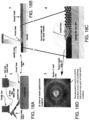
- the advantage of using the fiber-optic delivery system 717 is that the fibers 719 of the fiber-optic delivery system 717 form a very dense uniform network that produces a high resolution pixel pitch and therefore a better image when the electromagnetic radiation being emitted by the laser diode array 714 is ultimately applied in the curing of the colored powder coating materials 30. Additionally, the bundle of fibers 719 is lighter and easier to manipulate than a laser diode array stack. Further, the fiber bundle requires less optics to focus the diode power onto the target surface. As shown in Figure 18 , the fiber optic system disclosed with reference to Figure 17 may be implemented with rotation of the fiber optic delivery system so as to achieve angular transmission of the beams so as to converge the beams as disclosed above with reference to Figure 16 . Rotation may be achieve by rotating the fiber-optic delivery system 717 relative to the support assembly 724 or by providing optical elements within the fiber-optic delivery system 717 that will bend the light being passed through the fiber-optic delivery system 717.
- the fiber-optic delivery system 717 may be used in creating both an expanded beam 725 and a focused beam 727.
- Such an implementation is capable of achieving thermal gradient control while maintaining high processing speed and high spatial resolution.
- the electromagnetic radiation being emitted by the laser emitter 814 can also be manipulated by the addition of XY mirrors such as an available galvanometric control system 880 (see Figure 19 ). Delivery of the transmitted light to specific location on a substrate may also be achieved via stepper motors or robotic manipulators. The use of such a control system significantly increases the ease of application on compound surfaces. This arrangement is best suited for large structures such as aircraft and large trucks.
- Pixel density in particular is affected by additional factors such as control integration spacing.
- the number of diode elements and the footprint of the fiber delivery bundle increase the optical properties of the system.
- the colored powder coating materials can also determine image quality and image resolution. This is because there is a large selection of coatings with various melt viscosities.
- a laser emitter 814 is depicted whereby the laser energy is steered onto the target surface using a galvanometric control system 880 composed of a plurality of galvanometers 882x, 882y, 882z.
- the galvanometric control system 880 is coupled with a laser emitter 814 and its beam is first steered by a Z axis servo 882z and then scanned over the target surface using a predetermined power density.
- the surface is subsequently imaged and recorded by a radiometric infrared camera recording and this data is provided to the computer-based control system 840.
- the recorded data is analyzed by the computer-based control system 840 and dimensionally recorded over the target surface.
- the thermal anomalies are used to control the laser power over the exact same surface during a second rescan during which the colored powder coating materials 30 is applied and cured. Whereby the laser power is increased or decreased to produce a uniform temperature as desired by the applicator that is in accordance with the desired coating melt temperature.
- a closed loop thermal feedback system as described above may be used in conjunction with this embodiment so as to ensure that the colored powder coating materials are at and above the melt temperature for a specific period of time to optimize the melt flow of the coating. This technique makes for a much smoother coated surface and a much better image. Further this process causes the combined coats to be dithered and substantially integrated.
- the galvanometric control system 880 is a long wave (wavelengths longer than 5 ⁇ m) laser system
- additional value is provided because it is not as color sensitive as other types of laser such as systems where short-wave diode lasers are used. This is particularly true of very large professional images that require a very smooth uniform surface.
- the use of longer wavelength electromagnetic radiation also applies to those images that require a clear topcoat.
- a more powerful laser source with a much longer wavelength than what is available with most diode lasers is indispensable. This is because most diode lasers have short wavelengths as is typical with diode lasers designs. These wavelengths will pass directly through the clear coat top without any energy absorption.
- Another benefit of choosing to couple diode lasers for coating application in concert with long wave CO 2 lasers is that using both of them in unison can greatly enhance application speed. This is because many images have large and dominant color themes that can be more readily applied with a galvanometer-based CO 2 laser system. While the highly multi-pigmented pixel dense areas can be easily handled with diode arrays. The importance of color fidelity using this technology can be maintained in several distinct ways. The following is a short list of attributes that can be used to maintain the color fidelity of the original image.
- one of the keys to applying the coating pixel or dot color element is the correct application of laser power.
- New or unfamiliar powder coatings should be first tested and quantified before use in actual applications. This data then can be an added to a list or a lookup table of selectable coatings in the computer-based control system and can then be referred to at any time in the future for application control.
- the spot size should be as small as possible, in most cases the spot size should be on the order of 0.48 to 0.89mm (0.0192" to 0.035”) in diameter. The larger the spot size, the more granular the image will appear.
- the laser When a small portion of the target is scanned by the laser beam, the laser selectively radiates portions of the powder or the field area that the powder needs to adhere to.
- the beam is raster scanned over the entirety of the surface and is turned on and off or modulated selectively in order to fuse only those Picture Elements or dots where they are needed. Additionally, in areas of large contiguous color regions it is easier to apply a dot matrix at the furthest extent of the edges of the dominant color only.
- the interior of the contiguous region can then be over scanned (filled) in its entirety after the edges are established such as with text. Text is generally of the same color and is easier to fill in the internal area of a designated letter in a raster scan than with individual pixel or dot elements.
- the laser beam is scanned in the X direction and is incremented in the Y direction at the end of each field.
- the results and savings of time are much greater than that of using singular pixel or dot elements.
- the present invention considers the melt flow viscosity of the various materials in order to produce an image that is substantially integrated and dithered that produce smooth and consistent results.
- a final over scan of the entire image is produced with overlapping beam on the target area. This is also accomplished with the use of the raster scan in a XY pattern.
- an additional Z axis focusing element is included in the present invention as shown with reference to the embodiments disclosed with reference to Figures 6 , 7 , 8A , and 8B .
- This keeps power density on target consistent such that an appropriate cure and dwell time is maintained across the entirety of the surface.
- it is necessary to have a means which is readily available to calculate the distance from the objective to the target surface. Often this dimension can be obtained with the use of a distance monitoring device, a pre-scan of the surface with a computerized telemetry system, or in many cases a CAD drawing of the object being coated.
- the distance monitoring systems may be used alone or in combination to ensure that the contour of the substrate is being properly followed.
- the use of distance monitoring device and/or CAD drawings while applying images and coatings is aided by the fact that these images can be integrated in several steps.
- a compound or contour surface can be coated with a uniform power density as previously described and determined by the following.
- the means for which these images are integrated onto the substrate 26 in accordance with the present invention can be accomplished visually with obviated registration markers.
- a better and more accurate method is to use an electronic means of registration that keeps track of the segmented images and the relationship to each other.
- digital image projection devices 931, 1031 are conjunction with electromagnetic radiation sources 914, 1014.
- the digital image projection devices 931, 1031 are used not only for image placement, but also for image creation and fusing of the coating.
- an LCD screen 931 is positioned between the electromagnetic radiation source (that is, a laser emitter in accordance with a disclosed embodiment) 914 and a target 926.
- the LCD screen 931 controls the application of the electromagnetic radiation being emitted by the electromagnetic radiation source 914 to the target 926.
- the LCD screen 931 is used to generate specific patterns electrically.
- These patterns are then be projected onto a surface of the target 926 as the electromagnetic radiation being emitted by the electromagnetic radiation source 914 passes through the LCD screen 931 and onto the surface of the target 926.
- the electromagnetic radiation is transmitted onto the surface of the target 926 with sufficient radiant energy to melt and fuse polymers from which colored powder coating materials 30 are made.
- a large LCD screen 931 will be necessary where the radiant energy (laser or otherwise) is expanded uniformly over the LCD screen 931. With the power density requirements being well monitored and uniformly dispersed the LCD screen 931 lends itself directly to larger image application.
- a projector lens 935 is provided to condense image size. This image reduction also increases the power density within the range necessary to fuse or crosslink the desired coatings on the target surface.
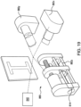
- an DMD (Digital Mirror Device) 1031 is positioned between the electromagnetic radiation source (that is, a laser emitter in accordance with a disclosed embodiment) 1014 and a target 1026.
- the DMD 1031 controls the reflection application of the electromagnetic radiation being emitted by the electromagnetic radiation source 1014 to the target 1026.
- the DMD 1031 is used to generate specific patterns electrically. These patterns are then projected onto a surface of the target 1026 as the electromagnetic radiation being emitted by the electromagnetic radiation source 1014 reflects off of the DMD 1031 and onto the surface of the target 1026.
- the electromagnetic radiation is transmitted onto the surface of the target 1026 with sufficient radiant energy to melt and fuse polymers from which colored powder coating materials 30 are made.
- a large DMD 1031 will be necessary where the radiant energy (laser or otherwise) is expanded uniformly over the DMD 1031.
- the DMD 1031 With the power density requirements being well monitored and uniformly dispersed the DMD 1031 lends itself directly to larger image application.
- plural lenses 1035 are positioned between the DMD 1031 and the target 1026 to condense image size. This image reduction also increases the power density within the range necessary to fuse or crosslink the desired coatings on the target surface.
- the electromagnetic radiation is emitted from the projector 1014 onto the DMD 1031 where the image formation is generated. This image is then captured and reduced by the lens elements 1035 and then focused onto the target item.
- This target surface of the substrate 1026 is coated with the correctly pigmented resin from which colored powder coating materials 30 are made that is to be fused to the target substrate 1026 at and where it is necessary for proper image formation.
- the same process as described above can be generated the same way using an appropriate LCD screen 931 with the image formed digitally within the LCD screen 931 itself.
- graphical image projection over the desired surface to be coated may be employed.
- the graphical image projection can be used to register specific points of image integration. It also can be used as an alignment facilitator when coupled with a human operator that aligns the galvanometer or galvanometer system at specific coordinates that are selected through a viewing camera that in turn images the same image graphical projection described above. This will allow a human operator to accurately align the projected image with the galvanometer control system 40.
- the use of low-power targeting lasers can be scanned over the area in a rapid manner that enables the user to confirm the placement of the image before the actual coating application begins.
- an additional attribute of present invention involves the ability to apply interlaminar conductive traces. This is similar to the production of multilayer circuit boards produced for the electronics industry. Where separate conductive traces are routed throughout the several laminations of the desired circuit board. This technique utilizes a series of successive coating layers 1113 applied involving conductive materials and nonconductive materials on top of individual layers or a substrate 1126.
- the substrate 1126 is first coated with an electrically nonconductive layer 1113 producing an insulating nonconductive layer.
- the nonconductive layer 1113 is then subsequently etched to form channels 1115 while substantially preserving its insulating properties in a prescribed path to receive and be filled with a conductive material 1117.
- the conductive material 1117 is then fused, using the concepts underlying the present invention, with sufficient electromagnetic radiation to form a solid body within the confines of the etched channel via a physical or chemical process. This establishes a circuit path.
- a layer of nonconductive material 1119 shall be cured in placed above the previous layer which will entrain the channels 1115 filled with conductive material 1117 between nonconductive material layers 1113, 1119.
- the nonconductive surface can be electronically accessed by ablating down to the conductive material layer at select points or through holes which will facilitate the creation of electrical circuits. Ablation can also be performed to reach the substrate to allow the substrate to integrate into the circuit as long as the substrate is conductive.
- the topmost nonconductive surface can also be a substrate to accept graphically applied coatings or the nonconductive surface can be a graphically illustrated with additional coatings.
- control techniques may also be utilized in combination with reduced scan fields to improve controlled uniformity over surfaces with compound topography.
- the use of telemetry and metrology - equipment can be integrated with the system in order to maintain dimensional integrity.
- a suitable conductive ink can be manufactured that easily fills the above described etched channels and that easily cured with long wave lasers is composed of the following.
- a radiation curable sample was made from the following components
- carbon nanotubes in the above mixture increases the absorption of long wave electromagnetic radiation and can be varied to control the rate of cure. Additionally, the addition of carbon nanotubes increases the flexure modulus of the silver electrical traces significantly. Further enhancement of conductive properties as well as to increase bond strength the addition of Poly(3,4-ethylenedioxythiophene) or PEDOT can be added or used for the entirety of the trace on its own.
Landscapes
- Engineering & Computer Science (AREA)
- Chemical & Material Sciences (AREA)
- Materials Engineering (AREA)
- Optics & Photonics (AREA)
- Physics & Mathematics (AREA)
- Mechanical Engineering (AREA)
- Manufacturing & Machinery (AREA)
- Health & Medical Sciences (AREA)
- Toxicology (AREA)
- Plasma & Fusion (AREA)
- Microelectronics & Electronic Packaging (AREA)
- General Health & Medical Sciences (AREA)
- Chemical Kinetics & Catalysis (AREA)
- Metallurgy (AREA)
- Organic Chemistry (AREA)
Claims (15)
- System zum Produzieren von Bildern direkt auf einer Oberfläche, umfassend:ein operatives Härtungssystem (18, 118, 218), aufweisend ein Wärmeerfassungssystem (120, 220, 320), eine Abstandsüberwachungsvorrichtung (122, 222, 322) und eine gerichtete Strahlungsenergiequelle (114);eine Trägeranordnung (124, 224, 324, 724) zum Halten des operativen Härtungssystems (18, 118, 218) relativ zu einem Substrat (126, 226);einen Bildgenerator (10, 110) für dreidimensionale Bilder undein computerbasiertes Steuersystem (40, 140, 240, 340, 740, 840), das Daten verarbeitet und das operative Härtungssystem (18, 118, 218) und die Trägeranordnung (124, 224, 324, 724) steuert;wobei die Datenverarbeitung mit dem Bildgenerator (10, 110) für dreidimensionale Bilder durchgeführt wird, wobei eine Bewegung der Trägeranordnung (124, 224, 324, 724) entlang orthogonalen Achsen bereitgestellt wird, wodurch ermöglicht wird, dass geschichtete Beschichtungen von Substraten (126, 226) ausgehärtet werden, um unter Verwendung von Informationen sowohl der Abstandsüberwachungsvorrichtung (122, 222, 322) als auch dem Wärmeerfassungssystem (120, 220, 320) die 3D-Bilder mit verschiedenen Formen und Größen zu bilden, wodurch ermöglicht wird, dass das operative Härtungssystem (18, 118, 218) in einer gewünschten Position relativ zu den geschichteten Beschichtungen gehalten wird, und wobei das operative Härtungssystem (18, 118, 218) farbige Pulverbeschichtungsmaterialien an Ursprungspunkten verschmilzt, dann das computerbasierte Steuersystem (40, 140, 240, 340, 740, 840) eine Pixelkoordinate auswählt, die eine Härtung der geschichteten Beschichtungen erfordert, und Bildelemente entlang einem vorgeschriebenen Pfad durch das computerbasierte Steuersystem (40, 140, 240, 340, 740, 840) erzeugt werden.
- System nach Anspruch 1, wobei die gerichtete Strahlungsenergiequelle (114) ein Laseremitter (114, 214) ist.
- System nach Anspruch 2, wobei der Laseremitter (114, 214) ein galvanometrisches Steuersystem (880) umfasst.
- System nach Anspruch 2, wobei der Laseremitter (114, 214) ein Diodenlaser (314) ist.
- System nach Anspruch 4, wobei der Diodenlaser (314) Piezoelemente (454a, 454b) umfasst.
- System nach Anspruch 4, wobei der Laseremitter (114, 214) ferner einen optischen Spiegel (350) und optische Fokussierelemente (351) umfasst, die emittierte elektromagnetische Strahlung an einer gewünschten Stelle fokussieren.
- System nach Anspruch 1, wobei die gerichtete Energiequelle (114) eine elektromagnetische Strahlungsquelle (914, 1014) und einen LCD-Bildschirm (931) umfasst und der LCD-Bildschirm (931) zwischen der elektromagnetischen Strahlungsquelle (914, 1014) und einem Ziel (326, 926, 1026) positioniert ist.
- System nach Anspruch 1, wobei die gerichtete Energiequelle (114) eine elektromagnetische Strahlungsquelle (914, 1014) und eine digitale Spiegelvorrichtung (1031) umfasst und die digitale Spiegelvorrichtung (1031) zwischen der elektromagnetischen Strahlungsquelle (914, 1014) und einem Ziel (326, 926, 1026) positioniert ist.
- System nach Anspruch 1, wobei die Trägeranordnung (124, 224, 324, 724) eine Bewegung des operativen Härtungssystems (18, 118, 218) in drei Dimensionen ermöglicht.
- System nach Anspruch 9, wobei die Trägeranordnung (124, 224, 324, 724) ein XY-Gerüst (132, 232) umfasst.
- System nach Anspruch 1, ferner umfassend ein geschlossenes Regelkreisüberwachungssystem (144, 244) zum schnellen Beurteilen einer Temperatur und Bestimmen eines ausreichenden Härtungszustands.
- System nach Anspruch 1, ferner umfassend ein ladungsgekoppeltes Bauelement, das eine zurückgesendete Streuung von elektromagnetischer Strahlung analysiert.
- System nach Anspruch 1, wobei die gerichtete Strahlungsenergiequelle (114) ein Laserdioden-Array (514, 614, 714) ist.
- System nach Anspruch 13, wobei das Laserdioden-Array (514, 614, 714) drehbar ist.
- System nach Anspruch 13, wobei Licht von dem Laserdioden-Array (514, 614, 714) mittels eines Lichtleiterabgabesystems (717) übertragen wird.
Applications Claiming Priority (3)
| Application Number | Priority Date | Filing Date | Title |
|---|---|---|---|
| US201862773930P | 2018-11-30 | 2018-11-30 | |
| US16/698,260 US11465353B2 (en) | 2018-11-30 | 2019-11-27 | High mobility 3D laser printing system |
| PCT/US2020/056753 WO2021108047A1 (en) | 2018-11-30 | 2020-10-22 | High mobility 3d laser printing system |
Publications (4)
| Publication Number | Publication Date |
|---|---|
| EP4065347A1 EP4065347A1 (de) | 2022-10-05 |
| EP4065347A4 EP4065347A4 (de) | 2023-11-08 |
| EP4065347C0 EP4065347C0 (de) | 2025-06-04 |
| EP4065347B1 true EP4065347B1 (de) | 2025-06-04 |
Family
ID=70849875
Family Applications (1)
| Application Number | Title | Priority Date | Filing Date |
|---|---|---|---|
| EP20893859.7A Active EP4065347B1 (de) | 2018-11-30 | 2020-10-22 | Hochgeschwindigkeits-3d-laserdrucksystem |
Country Status (4)
| Country | Link |
|---|---|
| US (1) | US11465353B2 (de) |
| EP (1) | EP4065347B1 (de) |
| AU (1) | AU2020392303A1 (de) |
| WO (1) | WO2021108047A1 (de) |
Families Citing this family (1)
| Publication number | Priority date | Publication date | Assignee | Title |
|---|---|---|---|---|
| EP3961557A1 (de) * | 2020-08-26 | 2022-03-02 | Siemens Aktiengesellschaft | Qualitätsinspektionsverfahren und anordnung für eine qualitätsinspektion |
Family Cites Families (20)
| Publication number | Priority date | Publication date | Assignee | Title |
|---|---|---|---|---|
| US5200230A (en) * | 1987-06-29 | 1993-04-06 | Dunfries Investments Limited | Laser coating process |
| JP3209641B2 (ja) | 1994-06-02 | 2001-09-17 | 三菱電機株式会社 | 光加工装置及び方法 |
| US7661387B2 (en) * | 2004-01-30 | 2010-02-16 | Dunfries Investment Limited | Dual laser coating apparatus and process |
| GB0508360D0 (en) | 2005-04-25 | 2005-06-01 | Sherwood Technology Ltd | Printing system |
| US7897214B2 (en) * | 2007-12-27 | 2011-03-01 | Dunfries Investment Limited | Laser applied multifunctional coatings for marine and aerospace vehicles |
| WO2010052098A1 (en) | 2008-11-07 | 2010-05-14 | Asml Netherlands B.V. | Scatterometer and lithographic apparatus |
| EP2641661B1 (de) * | 2012-03-20 | 2016-05-11 | Hexagon Technology Center GmbH | Graphisches Auftragssystem |
| US9321215B2 (en) | 2013-03-12 | 2016-04-26 | Orange Maker, Llc | 3D printing using spiral buildup |
| US10953609B1 (en) | 2013-03-22 | 2021-03-23 | Markforged, Inc. | Scanning print bed and part height in 3D printing |
| US10328685B2 (en) * | 2013-12-16 | 2019-06-25 | General Electric Company | Diode laser fiber array for powder bed fabrication or repair |
| US10239090B2 (en) | 2014-04-22 | 2019-03-26 | Photofusion Technologies Limited | Method and apparatus for coating a substrate utilizing multiple lasers while increasing quantum yield |
| CN208637788U (zh) | 2014-11-24 | 2019-03-22 | 斯特塔思有限公司 | 具有激光器组件的增材制造系统 |
| KR101787880B1 (ko) * | 2015-03-19 | 2017-11-15 | 전진환 | 컬러 3d 프린터 및 그 제어 방법 |
| WO2018091891A1 (en) | 2016-11-16 | 2018-05-24 | Photocentric Limited | Methods for making a metal, sand or ceramic object by additive manufacture and formulations for use in said methods |
| WO2018098395A1 (en) * | 2016-11-25 | 2018-05-31 | Glowforge Inc. | Improved engraving in a computer numerically controlled machine |
| US10773510B2 (en) | 2017-02-06 | 2020-09-15 | 3D Systems, Inc. | Scalable and fast three dimensional printing system |
| US10695865B2 (en) * | 2017-03-03 | 2020-06-30 | General Electric Company | Systems and methods for fabricating a component with at least one laser device |
| US11084132B2 (en) * | 2017-10-26 | 2021-08-10 | General Electric Company | Diode laser fiber array for contour of powder bed fabrication or repair |
| EP3552806A1 (de) * | 2018-04-09 | 2019-10-16 | Nederlandse Organisatie voor toegepast- natuurwetenschappelijk onderzoek TNO | Verfahren und vorrichtung zur herstellung eines objekts mittels generativer fertigung |
| US10994477B1 (en) * | 2019-11-01 | 2021-05-04 | Inkbit, LLC | Optical scanning for industrial metrology |
-
2019
- 2019-11-27 US US16/698,260 patent/US11465353B2/en active Active
-
2020
- 2020-10-22 AU AU2020392303A patent/AU2020392303A1/en active Pending
- 2020-10-22 EP EP20893859.7A patent/EP4065347B1/de active Active
- 2020-10-22 WO PCT/US2020/056753 patent/WO2021108047A1/en not_active Ceased
Also Published As
| Publication number | Publication date |
|---|---|
| EP4065347C0 (de) | 2025-06-04 |
| WO2021108047A1 (en) | 2021-06-03 |
| US20200171747A1 (en) | 2020-06-04 |
| EP4065347A1 (de) | 2022-10-05 |
| AU2020392303A1 (en) | 2022-06-09 |
| EP4065347A4 (de) | 2023-11-08 |
| US11465353B2 (en) | 2022-10-11 |
| CA3159153A1 (en) | 2021-06-03 |
Similar Documents
| Publication | Publication Date | Title |
|---|---|---|
| CN111295278B (zh) | 扫描系统的校准 | |
| EP2830882B1 (de) | Verfahren zum bedrucken eines objekts | |
| AU2005202167B2 (en) | Method of forming structures using drop-on-demand printing | |
| US20240342980A1 (en) | 3d printing to obtain a predefined surface quality | |
| US10075619B2 (en) | Networked digital imaging customization | |
| US20100221504A1 (en) | Method for producing a component with a relief surface and a component of this type | |
| US20230121401A1 (en) | Method for creating a print control profile for printing on a contoured axially symmetric object | |
| US20160311162A1 (en) | Novel color 3d printer based on energy-curable color coating on transparent or translucent base material | |
| JP6836897B2 (ja) | 造形物および造形方法 | |
| EP3094472B1 (de) | Verarbeitung von schichtdaten für ein system zur additiven fertigung | |
| EP3466646A1 (de) | Formvorrichtung, formverfahren und geformter gegenstand | |
| JP7474946B2 (ja) | 印刷装置 | |
| EP3530436A1 (de) | Formsystem, formverfahren, verfahren zur herstellung eines formobjekts sowie formobjekt | |
| EP4065347B1 (de) | Hochgeschwindigkeits-3d-laserdrucksystem | |
| EP3085544B1 (de) | Verfahren zum bedrucken eines medienobjekts in einem flachbettdrucksystem | |
| CA3159153C (en) | High mobility 3d laser printing system | |
| JP2020189444A (ja) | 印刷装置 | |
| US5819664A (en) | Process for creating textured images | |
| KR100996772B1 (ko) | 3차원 표면상에 코팅을 도포하는 방법 및 장치 | |
| JP2019166760A (ja) | 記録装置、及び記録装置の記録方法 | |
| CN103660602A (zh) | 用于激光上光系统和方法的标记材料 | |
| CN109791573A (zh) | 3d指示物体 | |
| CN112789158B (zh) | 用于选择物体的方位和/或位置的方法、装置和介质 | |
| US20200031150A1 (en) | Method of printing with gloss control | |
| JP6922470B2 (ja) | 情報処理装置、立体造形装置、立体造形システム、設定方法、及びプログラム |
Legal Events
| Date | Code | Title | Description |
|---|---|---|---|
| STAA | Information on the status of an ep patent application or granted ep patent |
Free format text: STATUS: THE INTERNATIONAL PUBLICATION HAS BEEN MADE |
|
| PUAI | Public reference made under article 153(3) epc to a published international application that has entered the european phase |
Free format text: ORIGINAL CODE: 0009012 |
|
| STAA | Information on the status of an ep patent application or granted ep patent |
Free format text: STATUS: REQUEST FOR EXAMINATION WAS MADE |
|
| 17P | Request for examination filed |
Effective date: 20220627 |
|
| AK | Designated contracting states |
Kind code of ref document: A1 Designated state(s): AL AT BE BG CH CY CZ DE DK EE ES FI FR GB GR HR HU IE IS IT LI LT LU LV MC MK MT NL NO PL PT RO RS SE SI SK SM TR |
|
| DAV | Request for validation of the european patent (deleted) | ||
| DAX | Request for extension of the european patent (deleted) | ||
| REG | Reference to a national code |
Ref country code: DE Ref legal event code: R079 Free format text: PREVIOUS MAIN CLASS: B29C0064386000 Ipc: B41J0002475000 Ref country code: DE Ref legal event code: R079 Ref document number: 602020052460 Country of ref document: DE Free format text: PREVIOUS MAIN CLASS: B29C0064386000 Ipc: B41J0002475000 |
|
| A4 | Supplementary search report drawn up and despatched |
Effective date: 20231010 |
|
| RIC1 | Information provided on ipc code assigned before grant |
Ipc: C23C 24/08 20060101ALI20231004BHEP Ipc: B41J 2/475 20060101AFI20231004BHEP |
|
| GRAP | Despatch of communication of intention to grant a patent |
Free format text: ORIGINAL CODE: EPIDOSNIGR1 |
|
| STAA | Information on the status of an ep patent application or granted ep patent |
Free format text: STATUS: GRANT OF PATENT IS INTENDED |
|
| RIC1 | Information provided on ipc code assigned before grant |
Ipc: B41J 3/407 20060101ALN20240725BHEP Ipc: C23C 24/08 20060101ALI20240725BHEP Ipc: B41J 2/475 20060101AFI20240725BHEP |
|
| INTG | Intention to grant announced |
Effective date: 20240807 |
|
| GRAS | Grant fee paid |
Free format text: ORIGINAL CODE: EPIDOSNIGR3 |
|
| GRAA | (expected) grant |
Free format text: ORIGINAL CODE: 0009210 |
|
| STAA | Information on the status of an ep patent application or granted ep patent |
Free format text: STATUS: THE PATENT HAS BEEN GRANTED |
|
| AK | Designated contracting states |
Kind code of ref document: B1 Designated state(s): AL AT BE BG CH CY CZ DE DK EE ES FI FR GB GR HR HU IE IS IT LI LT LU LV MC MK MT NL NO PL PT RO RS SE SI SK SM TR |
|
| REG | Reference to a national code |
Ref country code: GB Ref legal event code: FG4D |
|
| REG | Reference to a national code |
Ref country code: CH Ref legal event code: EP |
|
| REG | Reference to a national code |
Ref country code: DE Ref legal event code: R096 Ref document number: 602020052460 Country of ref document: DE |
|
| REG | Reference to a national code |
Ref country code: IE Ref legal event code: FG4D |
|
| U01 | Request for unitary effect filed |
Effective date: 20250623 |
|
| U07 | Unitary effect registered |
Designated state(s): AT BE BG DE DK EE FI FR IT LT LU LV MT NL PT RO SE SI Effective date: 20250701 |
|
| PG25 | Lapsed in a contracting state [announced via postgrant information from national office to epo] |
Ref country code: ES Free format text: LAPSE BECAUSE OF FAILURE TO SUBMIT A TRANSLATION OF THE DESCRIPTION OR TO PAY THE FEE WITHIN THE PRESCRIBED TIME-LIMIT Effective date: 20250604 |
|
| PG25 | Lapsed in a contracting state [announced via postgrant information from national office to epo] |
Ref country code: NO Free format text: LAPSE BECAUSE OF FAILURE TO SUBMIT A TRANSLATION OF THE DESCRIPTION OR TO PAY THE FEE WITHIN THE PRESCRIBED TIME-LIMIT Effective date: 20250904 Ref country code: GR Free format text: LAPSE BECAUSE OF FAILURE TO SUBMIT A TRANSLATION OF THE DESCRIPTION OR TO PAY THE FEE WITHIN THE PRESCRIBED TIME-LIMIT Effective date: 20250905 |
|
| PG25 | Lapsed in a contracting state [announced via postgrant information from national office to epo] |
Ref country code: PL Free format text: LAPSE BECAUSE OF FAILURE TO SUBMIT A TRANSLATION OF THE DESCRIPTION OR TO PAY THE FEE WITHIN THE PRESCRIBED TIME-LIMIT Effective date: 20250604 |
|
| PG25 | Lapsed in a contracting state [announced via postgrant information from national office to epo] |
Ref country code: HR Free format text: LAPSE BECAUSE OF FAILURE TO SUBMIT A TRANSLATION OF THE DESCRIPTION OR TO PAY THE FEE WITHIN THE PRESCRIBED TIME-LIMIT Effective date: 20250604 |
|
| PG25 | Lapsed in a contracting state [announced via postgrant information from national office to epo] |
Ref country code: RS Free format text: LAPSE BECAUSE OF FAILURE TO SUBMIT A TRANSLATION OF THE DESCRIPTION OR TO PAY THE FEE WITHIN THE PRESCRIBED TIME-LIMIT Effective date: 20250904 |
|
| U20 | Renewal fee for the european patent with unitary effect paid |
Year of fee payment: 6 Effective date: 20251029 |
|
| PG25 | Lapsed in a contracting state [announced via postgrant information from national office to epo] |
Ref country code: IS Free format text: LAPSE BECAUSE OF FAILURE TO SUBMIT A TRANSLATION OF THE DESCRIPTION OR TO PAY THE FEE WITHIN THE PRESCRIBED TIME-LIMIT Effective date: 20251004 |
|
| PGFP | Annual fee paid to national office [announced via postgrant information from national office to epo] |
Ref country code: GB Payment date: 20251030 Year of fee payment: 6 |
|
| PG25 | Lapsed in a contracting state [announced via postgrant information from national office to epo] |
Ref country code: SM Free format text: LAPSE BECAUSE OF FAILURE TO SUBMIT A TRANSLATION OF THE DESCRIPTION OR TO PAY THE FEE WITHIN THE PRESCRIBED TIME-LIMIT Effective date: 20250604 |
|
| PG25 | Lapsed in a contracting state [announced via postgrant information from national office to epo] |
Ref country code: CZ Free format text: LAPSE BECAUSE OF FAILURE TO SUBMIT A TRANSLATION OF THE DESCRIPTION OR TO PAY THE FEE WITHIN THE PRESCRIBED TIME-LIMIT Effective date: 20250604 |
|
| PG25 | Lapsed in a contracting state [announced via postgrant information from national office to epo] |
Ref country code: SK Free format text: LAPSE BECAUSE OF FAILURE TO SUBMIT A TRANSLATION OF THE DESCRIPTION OR TO PAY THE FEE WITHIN THE PRESCRIBED TIME-LIMIT Effective date: 20250604 |