EP4065320B1 - Cutting machine for transversely cutting logs of paper - Google Patents
Cutting machine for transversely cutting logs of paper Download PDFInfo
- Publication number
- EP4065320B1 EP4065320B1 EP20816320.4A EP20816320A EP4065320B1 EP 4065320 B1 EP4065320 B1 EP 4065320B1 EP 20816320 A EP20816320 A EP 20816320A EP 4065320 B1 EP4065320 B1 EP 4065320B1
- Authority
- EP
- European Patent Office
- Prior art keywords
- blade
- primary
- cutting
- grinding wheels
- arm
- Prior art date
- Legal status (The legal status is an assumption and is not a legal conclusion. Google has not performed a legal analysis and makes no representation as to the accuracy of the status listed.)
- Active
Links
Images
Classifications
-
- B—PERFORMING OPERATIONS; TRANSPORTING
- B26—HAND CUTTING TOOLS; CUTTING; SEVERING
- B26D—CUTTING; DETAILS COMMON TO MACHINES FOR PERFORATING, PUNCHING, CUTTING-OUT, STAMPING-OUT OR SEVERING
- B26D7/00—Details of apparatus for cutting, cutting-out, stamping-out, punching, perforating, or severing by means other than cutting
- B26D7/08—Means for treating work or cutting member to facilitate cutting
- B26D7/12—Means for treating work or cutting member to facilitate cutting by sharpening the cutting member
-
- B—PERFORMING OPERATIONS; TRANSPORTING
- B26—HAND CUTTING TOOLS; CUTTING; SEVERING
- B26D—CUTTING; DETAILS COMMON TO MACHINES FOR PERFORATING, PUNCHING, CUTTING-OUT, STAMPING-OUT OR SEVERING
- B26D1/00—Cutting through work characterised by the nature or movement of the cutting member or particular materials not otherwise provided for; Apparatus or machines therefor; Cutting members therefor
- B26D1/01—Cutting through work characterised by the nature or movement of the cutting member or particular materials not otherwise provided for; Apparatus or machines therefor; Cutting members therefor involving a cutting member which does not travel with the work
- B26D1/12—Cutting through work characterised by the nature or movement of the cutting member or particular materials not otherwise provided for; Apparatus or machines therefor; Cutting members therefor involving a cutting member which does not travel with the work having a cutting member moving about an axis
- B26D1/14—Cutting through work characterised by the nature or movement of the cutting member or particular materials not otherwise provided for; Apparatus or machines therefor; Cutting members therefor involving a cutting member which does not travel with the work having a cutting member moving about an axis with a circular cutting member, e.g. disc cutter
- B26D1/157—Cutting through work characterised by the nature or movement of the cutting member or particular materials not otherwise provided for; Apparatus or machines therefor; Cutting members therefor involving a cutting member which does not travel with the work having a cutting member moving about an axis with a circular cutting member, e.g. disc cutter rotating about a movable axis
- B26D1/16—Cutting through work characterised by the nature or movement of the cutting member or particular materials not otherwise provided for; Apparatus or machines therefor; Cutting members therefor involving a cutting member which does not travel with the work having a cutting member moving about an axis with a circular cutting member, e.g. disc cutter rotating about a movable axis mounted on a movable arm or the like
-
- B—PERFORMING OPERATIONS; TRANSPORTING
- B26—HAND CUTTING TOOLS; CUTTING; SEVERING
- B26D—CUTTING; DETAILS COMMON TO MACHINES FOR PERFORATING, PUNCHING, CUTTING-OUT, STAMPING-OUT OR SEVERING
- B26D3/00—Cutting work characterised by the nature of the cut made; Apparatus therefor
- B26D3/16—Cutting rods or tubes transversely
-
- B—PERFORMING OPERATIONS; TRANSPORTING
- B26—HAND CUTTING TOOLS; CUTTING; SEVERING
- B26D—CUTTING; DETAILS COMMON TO MACHINES FOR PERFORATING, PUNCHING, CUTTING-OUT, STAMPING-OUT OR SEVERING
- B26D2210/00—Machines or methods used for cutting special materials
- B26D2210/11—Machines or methods used for cutting special materials for cutting web rolls
Definitions
- the present invention relates to a cutting-off machine for the transversal cutting of logs of paper material.
- logs rolls of toilet paper, kitchen paper and paper for similar uses are obtained from the transversal cutting of rolls of greater length, commonly called “logs” and produced by machines called “rewinders” in which a predetermined amount of a paper material, consisting of one or more overlapping paper plies, is wrapped around itself, i.e. around cardboard tubes called “cores".
- cores cardboard tubes
- the logs produced by the rewinders are conveyed to a buffer store and, from this, to machines, called “cut-off machines” which perform the aforementioned transverse cut.
- the cutting-off machines have a platform on which guide channels for the logs are defined and, downstream of said channels, a cutting unit which comprises a disk blade suitably activated and moved to determine the transversal cut of the logs at a programmed rate in function of the length of the rolls to be obtained from the logs.
- the blades are usually associated with grinding wheels which cyclically intervene to restore the cutting profile of the blades themselves. Periodically, the blades of the cutting-off must be replaced due to wear which progressively reduces both the diameter and the cutting performance. Whenever a worn blade is replaced with a new one, the position of the grinding wheels relative to the blade must be adjusted.
- WO2016/030125 A1 discloses a machine for the transversal cutting of logs of paper material comprising an advancement path for the logs to be cut, a cutting unit with a replaceable disk-shaped blade that is supported in such a way as to be able to rotate around its own axis while it is subjected to a cyclic movement for cutting the logs and to allow the advancement of the logs along the advancement path, and a sharpening unit with two grinding wheels configured and controlled to intervene on the disk-shaped blade when the latter is to be sharpened.
- the grinding wheels are mounted on a support system comprising a mechanism for controlled approach of the grinding wheels to the blade configured to move each grinding wheel in a direction substantially parallel to its own rotation axis. Said mechanism acts in such a way as to bring a support slide of each grinding wheel to a nominal position relative to the blade, and to bring the grinding wheel close to the blade in a controlled manner by moving the grinding wheel with respect to the slide which is kept in said nominal position.
- the main object of the present invention is to propose a machine for cutting paper logs in which the positioning of the grinding wheels with respect to the blade replaced from time to time is automated and in which said positioning is substantially independent of the diameter of the blade.
- a cutting-off machine to which a cutting unit is applicable according to the present invention is of the type comprising:
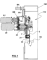
- Fig.1 schematically shows the main elements of a cutting-off machine (CM) in which a cutting unit in accordance with the present invention can be mounted, it being understood that the drawing is provided solely to allow the location of the cutting unit to be identified with respect to the path of the logs. It is also understood that the cutting-off machine can be made in any suitable way for executing the transversal cutting of logs of paper material, to obtain rolls of shorter length, by means of a cutting unit comprising a blade which acts transversely to the logs themselves.
- CM cutting-off machine
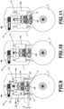
- the actuator (20) is connected to the blade (2) by means of a belt (21) which connects the central pin (22) of the same blade to the shaft (23) of the actuator (20) through a pulley arranged on the free end of the shaft (23). Furthermore, the plate (1) is rotated around an axis parallel to the axis of rotation of the blade (2) by means of a corresponding rotary actuator (A1) having a shaft (B1) parallel to the shaft (23) of the actuator that controls the rotation of the blade (2).
- the actuator (20) which for example is an electric motor, is integral with a box-shaped body (BB) located above said structure (SC) and inside which the belt (21) and the shafts (23) and (B1) are arranged.
- Said body (BB) is connected with a corresponding actuator (BA) which, through a screw (VA) acting on a nut bushing arranged on an upper side of the same body (BB), controls its vertical position, i.e. its positioning with respect to the underlying structure (SC). Consequently, by controlling the position of the body (BB), the blade (2) can be positioned at the desired height.
- the actuator (A1) which for example consists of an electric motor, is also integral with the body (BB).
- the blade (2) rotates around a respective axis (x-x) which is parallel to the axis of rotation of the plate (1) .
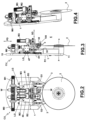
- a cutting unit (CU) comprises a plate (1) with an upper side (10), a lower side (11), a front side (F1) and a rear side (R1).
- the central pin (22) of the circular blade (2) is mounted on the lower side (11) of the plate (1) and is applied in a removable way on said pin in order to allow its replacement when necessary.
- the blade (2) is oriented parallel to the plate (1) and is positioned at a predetermined distance from the front side (F1) of the latter.
- On the plate (1) there are also mounted two grinding wheels (3) for sharpening the blade (2) and a device for positioning the grinding wheels (3) with respect to the blade (2).
- Each grinding wheel (3) is applied on a respective support shaft (30) whose axis (A30) has a predetermined inclination with respect to the front side (F1) of the plate (1) and, consequently, with respect to a corresponding side of the blade (2).
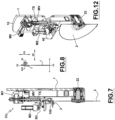
- Fig. 8 schematically shows the spindle (30) supporting a grinding wheel (3), the respective axis (A30), the inclination of the grinding wheel (3) in the sharpening position with respect to a side (A2) of the blade (2) and the lying plane (P2) of the latter.
- the aforementioned grinding wheel positioning device (3) comprises:
- the primary movement direction (PD) is a direction parallel to the plane (P2) where the blade (2) lies, i.e. a radial direction with respect to the latter, while the secondary movement direction (SD) is a direction parallel to the axis (x-x) of rotation of the blade (2).
- the primary carriage (4) can consist of two independent units (40, 41) to each of which a corresponding secondary carriage (42, 43) is connected.
- the primary carriage can consist of a single unit (400) to which both the secondary carriages (42, 43) are connected.
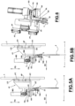
- the primary carriage (4) consists of two independent units, each of which consists of a body (40, 41) constrained to the internal side (F1) of the plate (1) by means of a rectilinear guide (LG) which allows its guided sliding along the primary movement direction (PD).
- the sliding of each body (40, 41) along the primary movement direction (PD) is controlled by a corresponding electric motor (M0, M1).
- Each motor (M0, M1) is fixed on the internal side (F1) of the plate (1) and drives a threaded shaft (TS) which engages a corresponding nut bushing (MV) formed on each body (40, 41). Therefore, each body (40, 41) can be moved independently from the other body by the respective motor (M0, M1) along the primary movement direction (PD) .
- Each of said bodies (40, 41) has a first side (4P) parallel to the internal side (F1) of the plate (1) and a second side (4H) orthogonal and below the first side (4P).
- the first side (4P) slides along the respective guide (LG).
- the second side (4H) constitutes a bracket structure whose function is indicated below.
- each of said bodies (40, 41) seen laterally, has a structure with a part (4P) parallel to the internal side (F1) of the plate (1) and a part (4H) orthogonal to the same internal side (F1) of the plate (1) and oriented towards the outside (E) so as to define a shelf above the blade (2).
- the movement of the two units that make up the primary carriage (4) is a guided movement thanks to the presence of the guides (LG) that constrain the bodies (40, 41) to the internal side (F1) of the plate (1).
- the references "PT" denote two sliding blocks arranged at a predetermined distance from each other on the side (4P) of each body (40, 41) and intended to slide on said guides (LG).
- Each of the secondary carriages (42, 43) has a first arm (PA) parallel to the bracket (4H) of the respective primary carriage, to which it is connected by means of a corresponding slide guide (G2, G3), and a second arm (SA) which is orthogonal to the first arm (PA) and, at its free end, supports the shaft (30) of a respective grinding wheel (3).
- the second arm (SA) passes through an opening (BL) of the bracket (4H), so that the grinding wheel (3) with its shaft (30) are below the bracket (4H) and the second arm (SA) is free to move in the opening (BL) according to the secondary movement direction (SD).
- a connecting rod (B2, B3) is connected to the first arm (PA) of each secondary carriage (42, 43) amd is connected to a corresponding electric motor (M2, M3).
- Each motor (M2, M3) is supported by a surface (SM) which each primary carriage (40, 41) has at a predetermined distance from its side (4P) parallel to the plate (1).
- Each connecting rod is connected to the first arm (PA) by means of a pin (PN) orthogonal both to the connecting rod and to the first arm. Therefore, each motor (M2, M3) can move the respective secondary carriage (42, 43) according to the secondary movement direction (SD).
- SD secondary movement direction
- This movement is a guided movement since each secondary carriage is connected to the primary carriage by means of a respective slide (G2, G3) which, in fact, is oriented according to the secondary direction (SD).
- each grinding wheel (3) is supported by the cutting unit (CU) in such a way that it can be moved both according to the primary movement direction (PD) and the secondary movement direction (SD).
- the bodies (40, 41) that make up the primary carriage (4) can be moved in the primary movement direction (PD) by means of the motors (M0, M1), while the secondary carriages (42, 43) can be moved on the primary carriage along the secondary movement direction (SD) by the motors (M2, M3).
- the grinding wheels (3) are oriented with their respective grinding surfaces (31) towards the plane (P2) where the blade (2) lies.
- the primary carriage is provided, in correspondence with its lower side, i.e. the side facing the blade (2), with an optical sensor (100) whose function is described below.
- the optical sensor (100) is mounted below the bracket (4H) of any of the bodies (40, 41) previously described.
- the optical axis (101) of the sensor (100) is spaced by a predetermined value (b) from a reference line, which can be the so-called "dipping line” (3L) of the grinding wheels (3), so as to intercept the cutting edge (200) of the blade (2), when the primary carriage approaches the latter, before the grinding wheels (3) are arranged in the sharpening position on the blade.
- the dipping line is a reference line of each grinding wheel (3), i.e. a known geometric parameter supplied by the manufacturer.
- This parameter identifies the correct position of the grinding wheel with respect to the blade for sharpening purposes.
- the dipping line of the grinding wheel must be in a position of tangency to the cutting edge of the blade, as shown in the diagram in Fig. 14 .
- the abrasive part of the grinding wheel interferes correctly with the area of the blade to be sharpened, i.e. an optimal contact condition is achieved between the grinding wheel and the blade during the sharpening phase.
- a possible operating mode of the device described above is the following.
- the primary carriage When a new blade is mounted on the cutting unit (CU), the primary carriage is moved along the primary movement direction (PD). Then, the optical sensor (100) detects the edge (200) of the blade (2), and the run of the primary carriage continues until it stops when the optical axis (101) has passed the said edge (200) of a value corresponding to the value (b) previously described.
- the optical sensor (100) is connected to the motors (M0, M1). In this way, the grinding wheels (3) are correctly positioned with respect to the two sides of the blade (2) for the subsequent sharpening phase.
- the secondary carriages (42, 43) are moved along the secondary movement direction (SD) by the motors (M2, M3) so that each grinding wheel (3) is brought with the respective surface (31) in contact with the corresponding side of the blade (2) which rotates around its own axis (x-x).
- This contact is detected through the same blade (2) which, in fact, undergoes a slowdown as a consequence of the contact itself.
- the motor (20) that drives the blade is controlled by a system equipped with a control function that ensures a constant rotation speed of the blade around the rotation axis (x-x) during the transversal cutting of the logs.
- the aforementioned motor (20) control function is temporarily deactivated.
- the contact of the wheels (3) with the blade (2) causes a slowdown of the latter and this condition is assumed as an indicator of the contact between the wheels and the blade.
- the run of the secondary carriages in the direction (SD) is stopped. Therefore, the grinding wheels (3) will always be correctly positioned on the blade (2) regardless of the state of wear, and therefore regardless of the actual diameter, of the blade itself.
- the stopping point of the primary carriage at the end of this run is not predefined but it depends on the diameter, and therefore on the degree of wear, of the blade mounted in the cutting unit.
- the actuators (M0, M1) that move the units (40, 41) of the primary carriage are controlled by an optical sensor (100) which is connected to the same primary carriage and detects the cutting edge (200) of the blade (2) and interrupts the run of the primary carriage along the primary movement direction (PD) after this detection, so that the run of the primary carriage is given by the length of a path comprised between the initial waiting position and a position of detection of the cutting edge (200) by the optical sensor (100) increased by a predetermined value (b).
- the secondary actuators (42, 43) are controlled so as to bring the abrasive side of the wheels (3) into contact with the blade (2).
- the value (b) measures the difference, along the direction (PD) of movement of the primary carriage, between the position of the optical sensor (100) projected on the plane (P2) of the blade (2) and the position of the line (L3) of the grinding wheels (3) projected on the same plane (P2).
- the primary carriage can be made up of only one unit (400), rather than two independent units.
- only one motor (M0) is provided for moving the single unit (400).
- the primary carriage is provided with the optical sensor (100) which controls its run towards the blade (2) as previously described.
- a cutting-off machine for the transversal cutting of logs in accordance with the present invention comprises:
- the optical sensor (100) can be replaced by a sensor of another type, for example an inductive sensor or an ultrasonic sensor.
- the cutting-off machine can also be provided with two sharpening units of the type described above.
- the two sharpening units are placed in different positions with respect to the blade (2) for acting each on a different area of the blade.
- This can be useful in the case of circular blades of large diameter, or of circular blades with bevels of different shapes along the radius, so that each sharpening unit can act on a corresponding area of the blade.
- the two sharpening units are identical to each other. With reference to the example shown in Fig.
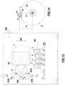
- the sensor (100) is associated with a slide (S10) mounted on guides (G10) oriented diagonally with respect to the direction (DS) of movement of a further slide (S1) on which the plate (1) is mounted.
- the plate (1) is moved towards the structure (SC).
- the movement of the plate is a function of the diameter of the blade (2) detected by the sensor (100).
- the actual diameter of the blade (2) is used to control the run of the primary carriage (40, 41; 400), not shown in Fig. 13 , towards the same blade in the sharpening phase.
- the sensor (100) detects the actual diameter of the blade (2).
- the position of the center of the blade with respect to the plate (1) is known and invariable, so that the detection of the cutting edge of the blade corresponds to the detection of the diameter of the latter.
- the movement of the primary carriage (40, 41; 400) along the primary movement direction (PD) is always controlled by a sensor which detects the diameter of the blade (2), so that, independently from the diameter of the latter, the grinding wheels (3) are always brought to the correct sharpening position, in which the dipping line of the grinding wheels is tangent to the cutting edge of the blade.
- said one or more actuators (MO, Ml) used to move the primary carriage (40, 41; 400) are controlled by a sensor (100) which detects the radius of the blade (2) and drives the interruption of the run of the primary carriage along the primary movement direction (PD) when the grinding wheels are arranged with their respective axes, relative to the rotation axis of the blade, at a distance (h) equal to radius (r2) of the blade increased by the radius (r3) of the grinding wheels and decreased by a predetermined value (b).
- the radius (r3) of the grinding wheels (3) is a known value.
Landscapes
- Life Sciences & Earth Sciences (AREA)
- Forests & Forestry (AREA)
- Engineering & Computer Science (AREA)
- Mechanical Engineering (AREA)
- Finish Polishing, Edge Sharpening, And Grinding By Specific Grinding Devices (AREA)
- Paper (AREA)
Priority Applications (1)
| Application Number | Priority Date | Filing Date | Title |
|---|---|---|---|
| RS20231240A RS64981B1 (sr) | 2019-11-25 | 2020-11-11 | Mašina za sečenje namenjena za poprečno sečenje koturova papira |
Applications Claiming Priority (2)
| Application Number | Priority Date | Filing Date | Title |
|---|---|---|---|
| IT102019000022044A IT201900022044A1 (it) | 2019-11-25 | 2019-11-25 | Macchina troncatrice per il taglio trasversale di logs di materiale cartaceo |
| PCT/IT2020/050275 WO2021106020A1 (en) | 2019-11-25 | 2020-11-11 | Cutting machine for transversely cutting logs of paper |
Publications (2)
| Publication Number | Publication Date |
|---|---|
| EP4065320A1 EP4065320A1 (en) | 2022-10-05 |
| EP4065320B1 true EP4065320B1 (en) | 2023-11-01 |
Family
ID=69904036
Family Applications (1)
| Application Number | Title | Priority Date | Filing Date |
|---|---|---|---|
| EP20816320.4A Active EP4065320B1 (en) | 2019-11-25 | 2020-11-11 | Cutting machine for transversely cutting logs of paper |
Country Status (9)
| Country | Link |
|---|---|
| US (1) | US11858161B2 (pl) |
| EP (1) | EP4065320B1 (pl) |
| BR (1) | BR112022007794A2 (pl) |
| ES (1) | ES2967636T3 (pl) |
| FI (1) | FI4065320T3 (pl) |
| IT (1) | IT201900022044A1 (pl) |
| PL (1) | PL4065320T3 (pl) |
| RS (1) | RS64981B1 (pl) |
| WO (1) | WO2021106020A1 (pl) |
Families Citing this family (1)
| Publication number | Priority date | Publication date | Assignee | Title |
|---|---|---|---|---|
| US20250135675A1 (en) * | 2022-02-02 | 2025-05-01 | O.M.T. S.R.L. | Apparatus and method for orbital operation of a blade for cutting rolls |
Citations (1)
| Publication number | Priority date | Publication date | Assignee | Title |
|---|---|---|---|---|
| WO2001072484A1 (en) * | 2000-03-28 | 2001-10-04 | Fabio Perini S.P.A. | Severing machine for articles of weblike material having a sharpening zone for the blades separate from the cutting zone |
Family Cites Families (9)
| Publication number | Priority date | Publication date | Assignee | Title |
|---|---|---|---|---|
| US4584917A (en) * | 1984-12-06 | 1986-04-29 | Paper Converting Machine Company | Automatic blade diameter compensation for log saws |
| US4843767A (en) * | 1988-03-28 | 1989-07-04 | Deere & Company | Automatic forage harvester knife sharpening system |
| ES2199052B1 (es) * | 2002-03-26 | 2005-02-01 | Danobat, S. Coop. | Maquina rectificadora de un rotor, con un cabezal rotatorio de dos muelas. |
| ITFI20020207A1 (it) * | 2002-10-30 | 2004-04-30 | Perini Fabio Spa | Gruppo di affilatura e macchina troncatrice comprendente almeno una lama e detto gruppo di affilatura |
| ITFI20040079A1 (it) * | 2004-04-01 | 2004-07-01 | Perini Fabio Spa | Macchina troncatrice con sistema di affilatura centrale |
| US20120184186A1 (en) * | 2011-01-14 | 2012-07-19 | Graham Jr Dave | Blade sharpening system and method |
| ES2701839T3 (es) * | 2014-08-29 | 2019-02-26 | Perini Fabio Spa | Máquina para cortar bobinas con muelas de afilado y procedimiento |
| IT201700081320A1 (it) * | 2017-07-18 | 2019-01-18 | Perini Fabio Spa | Gruppo di affilatura per macchina troncatrice e macchina comprendente detto gruppo |
| CN107336087A (zh) * | 2017-08-31 | 2017-11-10 | 中山市程博工业产品设计有限公司 | 一种可调位置的刀具自动打磨装置 |
-
2019
- 2019-11-25 IT IT102019000022044A patent/IT201900022044A1/it unknown
-
2020
- 2020-11-11 EP EP20816320.4A patent/EP4065320B1/en active Active
- 2020-11-11 BR BR112022007794A patent/BR112022007794A2/pt unknown
- 2020-11-11 FI FIEP20816320.4T patent/FI4065320T3/fi active
- 2020-11-11 RS RS20231240A patent/RS64981B1/sr unknown
- 2020-11-11 PL PL20816320.4T patent/PL4065320T3/pl unknown
- 2020-11-11 US US17/769,869 patent/US11858161B2/en active Active
- 2020-11-11 WO PCT/IT2020/050275 patent/WO2021106020A1/en not_active Ceased
- 2020-11-11 ES ES20816320T patent/ES2967636T3/es active Active
Patent Citations (1)
| Publication number | Priority date | Publication date | Assignee | Title |
|---|---|---|---|---|
| WO2001072484A1 (en) * | 2000-03-28 | 2001-10-04 | Fabio Perini S.P.A. | Severing machine for articles of weblike material having a sharpening zone for the blades separate from the cutting zone |
Also Published As
| Publication number | Publication date |
|---|---|
| ES2967636T3 (es) | 2024-05-03 |
| BR112022007794A2 (pt) | 2022-07-05 |
| FI4065320T3 (fi) | 2023-12-21 |
| IT201900022044A1 (it) | 2021-05-25 |
| US20220362959A1 (en) | 2022-11-17 |
| PL4065320T3 (pl) | 2024-03-18 |
| WO2021106020A1 (en) | 2021-06-03 |
| EP4065320A1 (en) | 2022-10-05 |
| US11858161B2 (en) | 2024-01-02 |
| RS64981B1 (sr) | 2024-01-31 |
Similar Documents
| Publication | Publication Date | Title |
|---|---|---|
| EP3479975B1 (en) | Method and machine for cutting logs of wound web material | |
| EP3077157B1 (en) | Device for sharpening blades | |
| CN107107363B (zh) | 用于切割幅材卷的切割机和方法 | |
| EP3074191B1 (en) | Control device for blades sharpening | |
| CN111032298A (zh) | 用于切割刀片的研磨单元、包括所述单元的机器及相关方法 | |
| EP4065320B1 (en) | Cutting machine for transversely cutting logs of paper | |
| EP2957184B1 (en) | Adjustment apparatus | |
| US20220016798A1 (en) | Cutting machine for paper rolls with a sharpening device | |
| EP2777899A1 (en) | Machine for working cardboard slabs | |
| US20240109218A1 (en) | Cutting-off machine for the transversal cutting of logs of paper material | |
| EP4065321B1 (en) | Cutting machine for transversely cutting logs of paper material | |
| US20220176579A1 (en) | Cutting machine for paper material logs with a sharpening unit | |
| WO2015079464A1 (en) | Device for sharpening blades | |
| US20150050865A1 (en) | Apparatus for sharpening rotating blades | |
| JPH06246634A (ja) | 心なし研削盤 | |
| US20250135675A1 (en) | Apparatus and method for orbital operation of a blade for cutting rolls | |
| CN211440264U (zh) | 一种薄膜分切装置的刀架结构 | |
| RU2021131228A (ru) | Резальная машина с затачивающим устройством, предназначенная для бумажных рулонов | |
| RU2021131238A (ru) | Резальная машина с затачивающим устройством, предназначенная для логов бумажного материала |
Legal Events
| Date | Code | Title | Description |
|---|---|---|---|
| STAA | Information on the status of an ep patent application or granted ep patent |
Free format text: STATUS: UNKNOWN |
|
| STAA | Information on the status of an ep patent application or granted ep patent |
Free format text: STATUS: THE INTERNATIONAL PUBLICATION HAS BEEN MADE |
|
| PUAI | Public reference made under article 153(3) epc to a published international application that has entered the european phase |
Free format text: ORIGINAL CODE: 0009012 |
|
| STAA | Information on the status of an ep patent application or granted ep patent |
Free format text: STATUS: REQUEST FOR EXAMINATION WAS MADE |
|
| 17P | Request for examination filed |
Effective date: 20220412 |
|
| AK | Designated contracting states |
Kind code of ref document: A1 Designated state(s): AL AT BE BG CH CY CZ DE DK EE ES FI FR GB GR HR HU IE IS IT LI LT LU LV MC MK MT NL NO PL PT RO RS SE SI SK SM TR |
|
| DAV | Request for validation of the european patent (deleted) | ||
| DAX | Request for extension of the european patent (deleted) | ||
| GRAP | Despatch of communication of intention to grant a patent |
Free format text: ORIGINAL CODE: EPIDOSNIGR1 |
|
| STAA | Information on the status of an ep patent application or granted ep patent |
Free format text: STATUS: GRANT OF PATENT IS INTENDED |
|
| INTG | Intention to grant announced |
Effective date: 20230727 |
|
| RIN1 | Information on inventor provided before grant (corrected) |
Inventor name: GUARINI, CIRO Inventor name: BETTI, GABRIELE |
|
| GRAS | Grant fee paid |
Free format text: ORIGINAL CODE: EPIDOSNIGR3 |
|
| GRAA | (expected) grant |
Free format text: ORIGINAL CODE: 0009210 |
|
| STAA | Information on the status of an ep patent application or granted ep patent |
Free format text: STATUS: THE PATENT HAS BEEN GRANTED |
|
| AK | Designated contracting states |
Kind code of ref document: B1 Designated state(s): AL AT BE BG CH CY CZ DE DK EE ES FI FR GB GR HR HU IE IS IT LI LT LU LV MC MK MT NL NO PL PT RO RS SE SI SK SM TR |
|
| REG | Reference to a national code |
Ref country code: GB Ref legal event code: FG4D |
|
| REG | Reference to a national code |
Ref country code: CH Ref legal event code: EP |
|
| REG | Reference to a national code |
Ref country code: IE Ref legal event code: FG4D |
|
| REG | Reference to a national code |
Ref country code: DE Ref legal event code: R096 Ref document number: 602020020429 Country of ref document: DE |
|
| REG | Reference to a national code |
Ref country code: FI Ref legal event code: FGE |
|
| REG | Reference to a national code |
Ref country code: SE Ref legal event code: TRGR |
|
| REG | Reference to a national code |
Ref country code: LT Ref legal event code: MG9D |
|
| REG | Reference to a national code |
Ref country code: NL Ref legal event code: MP Effective date: 20231101 |
|
| PG25 | Lapsed in a contracting state [announced via postgrant information from national office to epo] |
Ref country code: GR Free format text: LAPSE BECAUSE OF FAILURE TO SUBMIT A TRANSLATION OF THE DESCRIPTION OR TO PAY THE FEE WITHIN THE PRESCRIBED TIME-LIMIT Effective date: 20240202 |
|
| PG25 | Lapsed in a contracting state [announced via postgrant information from national office to epo] |
Ref country code: IS Free format text: LAPSE BECAUSE OF FAILURE TO SUBMIT A TRANSLATION OF THE DESCRIPTION OR TO PAY THE FEE WITHIN THE PRESCRIBED TIME-LIMIT Effective date: 20240301 |
|
| PG25 | Lapsed in a contracting state [announced via postgrant information from national office to epo] |
Ref country code: LT Free format text: LAPSE BECAUSE OF FAILURE TO SUBMIT A TRANSLATION OF THE DESCRIPTION OR TO PAY THE FEE WITHIN THE PRESCRIBED TIME-LIMIT Effective date: 20231101 |
|
| REG | Reference to a national code |
Ref country code: AT Ref legal event code: MK05 Ref document number: 1626697 Country of ref document: AT Kind code of ref document: T Effective date: 20231101 |
|
| PG25 | Lapsed in a contracting state [announced via postgrant information from national office to epo] |
Ref country code: NL Free format text: LAPSE BECAUSE OF FAILURE TO SUBMIT A TRANSLATION OF THE DESCRIPTION OR TO PAY THE FEE WITHIN THE PRESCRIBED TIME-LIMIT Effective date: 20231101 |
|
| PG25 | Lapsed in a contracting state [announced via postgrant information from national office to epo] |
Ref country code: AT Free format text: LAPSE BECAUSE OF FAILURE TO SUBMIT A TRANSLATION OF THE DESCRIPTION OR TO PAY THE FEE WITHIN THE PRESCRIBED TIME-LIMIT Effective date: 20231101 |
|
| PG25 | Lapsed in a contracting state [announced via postgrant information from national office to epo] |
Ref country code: NL Free format text: LAPSE BECAUSE OF FAILURE TO SUBMIT A TRANSLATION OF THE DESCRIPTION OR TO PAY THE FEE WITHIN THE PRESCRIBED TIME-LIMIT Effective date: 20231101 Ref country code: LT Free format text: LAPSE BECAUSE OF FAILURE TO SUBMIT A TRANSLATION OF THE DESCRIPTION OR TO PAY THE FEE WITHIN THE PRESCRIBED TIME-LIMIT Effective date: 20231101 Ref country code: IT Free format text: LAPSE BECAUSE OF NON-PAYMENT OF DUE FEES Effective date: 20231111 Ref country code: IS Free format text: LAPSE BECAUSE OF FAILURE TO SUBMIT A TRANSLATION OF THE DESCRIPTION OR TO PAY THE FEE WITHIN THE PRESCRIBED TIME-LIMIT Effective date: 20240301 Ref country code: GR Free format text: LAPSE BECAUSE OF FAILURE TO SUBMIT A TRANSLATION OF THE DESCRIPTION OR TO PAY THE FEE WITHIN THE PRESCRIBED TIME-LIMIT Effective date: 20240202 Ref country code: BG Free format text: LAPSE BECAUSE OF FAILURE TO SUBMIT A TRANSLATION OF THE DESCRIPTION OR TO PAY THE FEE WITHIN THE PRESCRIBED TIME-LIMIT Effective date: 20240201 Ref country code: AT Free format text: LAPSE BECAUSE OF FAILURE TO SUBMIT A TRANSLATION OF THE DESCRIPTION OR TO PAY THE FEE WITHIN THE PRESCRIBED TIME-LIMIT Effective date: 20231101 Ref country code: PT Free format text: LAPSE BECAUSE OF FAILURE TO SUBMIT A TRANSLATION OF THE DESCRIPTION OR TO PAY THE FEE WITHIN THE PRESCRIBED TIME-LIMIT Effective date: 20240301 |
|
| REG | Reference to a national code |
Ref country code: ES Ref legal event code: FG2A Ref document number: 2967636 Country of ref document: ES Kind code of ref document: T3 Effective date: 20240503 |
|
| PG25 | Lapsed in a contracting state [announced via postgrant information from national office to epo] |
Ref country code: NO Free format text: LAPSE BECAUSE OF FAILURE TO SUBMIT A TRANSLATION OF THE DESCRIPTION OR TO PAY THE FEE WITHIN THE PRESCRIBED TIME-LIMIT Effective date: 20240201 Ref country code: LV Free format text: LAPSE BECAUSE OF FAILURE TO SUBMIT A TRANSLATION OF THE DESCRIPTION OR TO PAY THE FEE WITHIN THE PRESCRIBED TIME-LIMIT Effective date: 20231101 Ref country code: HR Free format text: LAPSE BECAUSE OF FAILURE TO SUBMIT A TRANSLATION OF THE DESCRIPTION OR TO PAY THE FEE WITHIN THE PRESCRIBED TIME-LIMIT Effective date: 20231101 |
|
| REG | Reference to a national code |
Ref country code: CH Ref legal event code: PL |
|
| PG25 | Lapsed in a contracting state [announced via postgrant information from national office to epo] |
Ref country code: DK Free format text: LAPSE BECAUSE OF FAILURE TO SUBMIT A TRANSLATION OF THE DESCRIPTION OR TO PAY THE FEE WITHIN THE PRESCRIBED TIME-LIMIT Effective date: 20231101 |
|
| PG25 | Lapsed in a contracting state [announced via postgrant information from national office to epo] |
Ref country code: LU Free format text: LAPSE BECAUSE OF NON-PAYMENT OF DUE FEES Effective date: 20231111 |
|
| PG25 | Lapsed in a contracting state [announced via postgrant information from national office to epo] |
Ref country code: CH Free format text: LAPSE BECAUSE OF NON-PAYMENT OF DUE FEES Effective date: 20231130 |
|
| PG25 | Lapsed in a contracting state [announced via postgrant information from national office to epo] |
Ref country code: CZ Free format text: LAPSE BECAUSE OF FAILURE TO SUBMIT A TRANSLATION OF THE DESCRIPTION OR TO PAY THE FEE WITHIN THE PRESCRIBED TIME-LIMIT Effective date: 20231101 |
|
| PG25 | Lapsed in a contracting state [announced via postgrant information from national office to epo] |
Ref country code: SK Free format text: LAPSE BECAUSE OF FAILURE TO SUBMIT A TRANSLATION OF THE DESCRIPTION OR TO PAY THE FEE WITHIN THE PRESCRIBED TIME-LIMIT Effective date: 20231101 |
|
| PG25 | Lapsed in a contracting state [announced via postgrant information from national office to epo] |
Ref country code: SM Free format text: LAPSE BECAUSE OF FAILURE TO SUBMIT A TRANSLATION OF THE DESCRIPTION OR TO PAY THE FEE WITHIN THE PRESCRIBED TIME-LIMIT Effective date: 20231101 Ref country code: SK Free format text: LAPSE BECAUSE OF FAILURE TO SUBMIT A TRANSLATION OF THE DESCRIPTION OR TO PAY THE FEE WITHIN THE PRESCRIBED TIME-LIMIT Effective date: 20231101 Ref country code: LU Free format text: LAPSE BECAUSE OF NON-PAYMENT OF DUE FEES Effective date: 20231111 Ref country code: EE Free format text: LAPSE BECAUSE OF FAILURE TO SUBMIT A TRANSLATION OF THE DESCRIPTION OR TO PAY THE FEE WITHIN THE PRESCRIBED TIME-LIMIT Effective date: 20231101 Ref country code: DK Free format text: LAPSE BECAUSE OF FAILURE TO SUBMIT A TRANSLATION OF THE DESCRIPTION OR TO PAY THE FEE WITHIN THE PRESCRIBED TIME-LIMIT Effective date: 20231101 Ref country code: CZ Free format text: LAPSE BECAUSE OF FAILURE TO SUBMIT A TRANSLATION OF THE DESCRIPTION OR TO PAY THE FEE WITHIN THE PRESCRIBED TIME-LIMIT Effective date: 20231101 Ref country code: CH Free format text: LAPSE BECAUSE OF NON-PAYMENT OF DUE FEES Effective date: 20231130 |
|
| REG | Reference to a national code |
Ref country code: BE Ref legal event code: MM Effective date: 20231130 |
|
| REG | Reference to a national code |
Ref country code: DE Ref legal event code: R097 Ref document number: 602020020429 Country of ref document: DE |
|
| PG25 | Lapsed in a contracting state [announced via postgrant information from national office to epo] |
Ref country code: MC Free format text: LAPSE BECAUSE OF FAILURE TO SUBMIT A TRANSLATION OF THE DESCRIPTION OR TO PAY THE FEE WITHIN THE PRESCRIBED TIME-LIMIT Effective date: 20231101 |
|
| PG25 | Lapsed in a contracting state [announced via postgrant information from national office to epo] |
Ref country code: MC Free format text: LAPSE BECAUSE OF FAILURE TO SUBMIT A TRANSLATION OF THE DESCRIPTION OR TO PAY THE FEE WITHIN THE PRESCRIBED TIME-LIMIT Effective date: 20231101 |
|
| PLBE | No opposition filed within time limit |
Free format text: ORIGINAL CODE: 0009261 |
|
| STAA | Information on the status of an ep patent application or granted ep patent |
Free format text: STATUS: NO OPPOSITION FILED WITHIN TIME LIMIT |
|
| REG | Reference to a national code |
Ref country code: IE Ref legal event code: MM4A |
|
| 26N | No opposition filed |
Effective date: 20240802 |
|
| PG25 | Lapsed in a contracting state [announced via postgrant information from national office to epo] |
Ref country code: IE Free format text: LAPSE BECAUSE OF NON-PAYMENT OF DUE FEES Effective date: 20231111 |
|
| PG25 | Lapsed in a contracting state [announced via postgrant information from national office to epo] |
Ref country code: BE Free format text: LAPSE BECAUSE OF NON-PAYMENT OF DUE FEES Effective date: 20231130 |
|
| PG25 | Lapsed in a contracting state [announced via postgrant information from national office to epo] |
Ref country code: SI Free format text: LAPSE BECAUSE OF FAILURE TO SUBMIT A TRANSLATION OF THE DESCRIPTION OR TO PAY THE FEE WITHIN THE PRESCRIBED TIME-LIMIT Effective date: 20231101 |
|
| PG25 | Lapsed in a contracting state [announced via postgrant information from national office to epo] |
Ref country code: SI Free format text: LAPSE BECAUSE OF FAILURE TO SUBMIT A TRANSLATION OF THE DESCRIPTION OR TO PAY THE FEE WITHIN THE PRESCRIBED TIME-LIMIT Effective date: 20231101 Ref country code: IE Free format text: LAPSE BECAUSE OF NON-PAYMENT OF DUE FEES Effective date: 20231111 Ref country code: BE Free format text: LAPSE BECAUSE OF NON-PAYMENT OF DUE FEES Effective date: 20231130 |
|
| PG25 | Lapsed in a contracting state [announced via postgrant information from national office to epo] |
Ref country code: IT Free format text: LAPSE BECAUSE OF NON-PAYMENT OF DUE FEES Effective date: 20231111 |
|
| PGRI | Patent reinstated in contracting state [announced from national office to epo] |
Ref country code: IT Effective date: 20231130 |
|
| PG25 | Lapsed in a contracting state [announced via postgrant information from national office to epo] |
Ref country code: CY Free format text: LAPSE BECAUSE OF FAILURE TO SUBMIT A TRANSLATION OF THE DESCRIPTION OR TO PAY THE FEE WITHIN THE PRESCRIBED TIME-LIMIT; INVALID AB INITIO Effective date: 20201111 |
|
| PG25 | Lapsed in a contracting state [announced via postgrant information from national office to epo] |
Ref country code: HU Free format text: LAPSE BECAUSE OF FAILURE TO SUBMIT A TRANSLATION OF THE DESCRIPTION OR TO PAY THE FEE WITHIN THE PRESCRIBED TIME-LIMIT; INVALID AB INITIO Effective date: 20201111 |
|
| PGFP | Annual fee paid to national office [announced via postgrant information from national office to epo] |
Ref country code: DE Payment date: 20251119 Year of fee payment: 6 |
|
| PGFP | Annual fee paid to national office [announced via postgrant information from national office to epo] |
Ref country code: GB Payment date: 20251121 Year of fee payment: 6 |
|
| PGFP | Annual fee paid to national office [announced via postgrant information from national office to epo] |
Ref country code: FI Payment date: 20251125 Year of fee payment: 6 Ref country code: IT Payment date: 20251023 Year of fee payment: 6 |
|
| PGFP | Annual fee paid to national office [announced via postgrant information from national office to epo] |
Ref country code: FR Payment date: 20251126 Year of fee payment: 6 |
|
| PGFP | Annual fee paid to national office [announced via postgrant information from national office to epo] |
Ref country code: TR Payment date: 20251104 Year of fee payment: 6 |
|
| PGFP | Annual fee paid to national office [announced via postgrant information from national office to epo] |
Ref country code: SE Payment date: 20251119 Year of fee payment: 6 |
|
| PGFP | Annual fee paid to national office [announced via postgrant information from national office to epo] |
Ref country code: PL Payment date: 20251106 Year of fee payment: 6 |
|
| PGFP | Annual fee paid to national office [announced via postgrant information from national office to epo] |
Ref country code: RO Payment date: 20251103 Year of fee payment: 6 |
|
| PGFP | Annual fee paid to national office [announced via postgrant information from national office to epo] |
Ref country code: RS Payment date: 20251031 Year of fee payment: 6 |
|
| PGFP | Annual fee paid to national office [announced via postgrant information from national office to epo] |
Ref country code: ES Payment date: 20251229 Year of fee payment: 6 |