EP4065290B1 - Harzhaftungs-fehlerdetektion - Google Patents
Harzhaftungs-fehlerdetektion Download PDFInfo
- Publication number
- EP4065290B1 EP4065290B1 EP20891503.3A EP20891503A EP4065290B1 EP 4065290 B1 EP4065290 B1 EP 4065290B1 EP 20891503 A EP20891503 A EP 20891503A EP 4065290 B1 EP4065290 B1 EP 4065290B1
- Authority
- EP
- European Patent Office
- Prior art keywords
- image
- slurry
- additive manufacturing
- layer
- volume
- Prior art date
- Legal status (The legal status is an assumption and is not a legal conclusion. Google has not performed a legal analysis and makes no representation as to the accuracy of the status listed.)
- Active
Links
Images


Classifications
-
- B—PERFORMING OPERATIONS; TRANSPORTING
- B22—CASTING; POWDER METALLURGY
- B22F—WORKING METALLIC POWDER; MANUFACTURE OF ARTICLES FROM METALLIC POWDER; MAKING METALLIC POWDER; APPARATUS OR DEVICES SPECIALLY ADAPTED FOR METALLIC POWDER
- B22F10/00—Additive manufacturing of workpieces or articles from metallic powder
- B22F10/80—Data acquisition or data processing
- B22F10/85—Data acquisition or data processing for controlling or regulating additive manufacturing processes
-
- B—PERFORMING OPERATIONS; TRANSPORTING
- B22—CASTING; POWDER METALLURGY
- B22F—WORKING METALLIC POWDER; MANUFACTURE OF ARTICLES FROM METALLIC POWDER; MAKING METALLIC POWDER; APPARATUS OR DEVICES SPECIALLY ADAPTED FOR METALLIC POWDER
- B22F12/00—Apparatus or devices specially adapted for additive manufacturing; Auxiliary means for additive manufacturing; Combinations of additive manufacturing apparatus or devices with other processing apparatus or devices
- B22F12/90—Means for process control, e.g. cameras or sensors
-
- B—PERFORMING OPERATIONS; TRANSPORTING
- B29—WORKING OF PLASTICS; WORKING OF SUBSTANCES IN A PLASTIC STATE IN GENERAL
- B29C—SHAPING OR JOINING OF PLASTICS; SHAPING OF MATERIAL IN A PLASTIC STATE, NOT OTHERWISE PROVIDED FOR; AFTER-TREATMENT OF THE SHAPED PRODUCTS, e.g. REPAIRING
- B29C64/00—Additive manufacturing, i.e. manufacturing of three-dimensional [3D] objects by additive deposition, additive agglomeration or additive layering, e.g. by 3D printing, stereolithography or selective laser sintering
- B29C64/10—Processes of additive manufacturing
- B29C64/106—Processes of additive manufacturing using only liquids or viscous materials, e.g. depositing a continuous bead of viscous material
- B29C64/124—Processes of additive manufacturing using only liquids or viscous materials, e.g. depositing a continuous bead of viscous material using layers of liquid which are selectively solidified
- B29C64/129—Processes of additive manufacturing using only liquids or viscous materials, e.g. depositing a continuous bead of viscous material using layers of liquid which are selectively solidified characterised by the energy source therefor, e.g. by global irradiation combined with a mask
- B29C64/135—Processes of additive manufacturing using only liquids or viscous materials, e.g. depositing a continuous bead of viscous material using layers of liquid which are selectively solidified characterised by the energy source therefor, e.g. by global irradiation combined with a mask the energy source being concentrated, e.g. scanning lasers or focused light sources
-
- B—PERFORMING OPERATIONS; TRANSPORTING
- B29—WORKING OF PLASTICS; WORKING OF SUBSTANCES IN A PLASTIC STATE IN GENERAL
- B29C—SHAPING OR JOINING OF PLASTICS; SHAPING OF MATERIAL IN A PLASTIC STATE, NOT OTHERWISE PROVIDED FOR; AFTER-TREATMENT OF THE SHAPED PRODUCTS, e.g. REPAIRING
- B29C64/00—Additive manufacturing, i.e. manufacturing of three-dimensional [3D] objects by additive deposition, additive agglomeration or additive layering, e.g. by 3D printing, stereolithography or selective laser sintering
- B29C64/20—Apparatus for additive manufacturing; Details thereof or accessories therefor
- B29C64/205—Means for applying layers
- B29C64/223—Foils or films, e.g. for transferring layers of building material from one working station to another
-
- B—PERFORMING OPERATIONS; TRANSPORTING
- B29—WORKING OF PLASTICS; WORKING OF SUBSTANCES IN A PLASTIC STATE IN GENERAL
- B29C—SHAPING OR JOINING OF PLASTICS; SHAPING OF MATERIAL IN A PLASTIC STATE, NOT OTHERWISE PROVIDED FOR; AFTER-TREATMENT OF THE SHAPED PRODUCTS, e.g. REPAIRING
- B29C64/00—Additive manufacturing, i.e. manufacturing of three-dimensional [3D] objects by additive deposition, additive agglomeration or additive layering, e.g. by 3D printing, stereolithography or selective laser sintering
- B29C64/20—Apparatus for additive manufacturing; Details thereof or accessories therefor
- B29C64/264—Arrangements for irradiation
- B29C64/268—Arrangements for irradiation using laser beams; using electron beams [EB]
-
- B—PERFORMING OPERATIONS; TRANSPORTING
- B29—WORKING OF PLASTICS; WORKING OF SUBSTANCES IN A PLASTIC STATE IN GENERAL
- B29C—SHAPING OR JOINING OF PLASTICS; SHAPING OF MATERIAL IN A PLASTIC STATE, NOT OTHERWISE PROVIDED FOR; AFTER-TREATMENT OF THE SHAPED PRODUCTS, e.g. REPAIRING
- B29C64/00—Additive manufacturing, i.e. manufacturing of three-dimensional [3D] objects by additive deposition, additive agglomeration or additive layering, e.g. by 3D printing, stereolithography or selective laser sintering
- B29C64/30—Auxiliary operations or equipment
- B29C64/386—Data acquisition or data processing for additive manufacturing
- B29C64/393—Data acquisition or data processing for additive manufacturing for controlling or regulating additive manufacturing processes
-
- B—PERFORMING OPERATIONS; TRANSPORTING
- B33—ADDITIVE MANUFACTURING TECHNOLOGY
- B33Y—ADDITIVE MANUFACTURING, i.e. MANUFACTURING OF THREE-DIMENSIONAL [3D] OBJECTS BY ADDITIVE DEPOSITION, ADDITIVE AGGLOMERATION OR ADDITIVE LAYERING, e.g. BY 3D PRINTING, STEREOLITHOGRAPHY OR SELECTIVE LASER SINTERING
- B33Y10/00—Processes of additive manufacturing
-
- B—PERFORMING OPERATIONS; TRANSPORTING
- B33—ADDITIVE MANUFACTURING TECHNOLOGY
- B33Y—ADDITIVE MANUFACTURING, i.e. MANUFACTURING OF THREE-DIMENSIONAL [3D] OBJECTS BY ADDITIVE DEPOSITION, ADDITIVE AGGLOMERATION OR ADDITIVE LAYERING, e.g. BY 3D PRINTING, STEREOLITHOGRAPHY OR SELECTIVE LASER SINTERING
- B33Y30/00—Apparatus for additive manufacturing; Details thereof or accessories therefor
-
- B—PERFORMING OPERATIONS; TRANSPORTING
- B33—ADDITIVE MANUFACTURING TECHNOLOGY
- B33Y—ADDITIVE MANUFACTURING, i.e. MANUFACTURING OF THREE-DIMENSIONAL [3D] OBJECTS BY ADDITIVE DEPOSITION, ADDITIVE AGGLOMERATION OR ADDITIVE LAYERING, e.g. BY 3D PRINTING, STEREOLITHOGRAPHY OR SELECTIVE LASER SINTERING
- B33Y50/00—Data acquisition or data processing for additive manufacturing
- B33Y50/02—Data acquisition or data processing for additive manufacturing for controlling or regulating additive manufacturing processes
-
- B—PERFORMING OPERATIONS; TRANSPORTING
- B33—ADDITIVE MANUFACTURING TECHNOLOGY
- B33Y—ADDITIVE MANUFACTURING, i.e. MANUFACTURING OF THREE-DIMENSIONAL [3D] OBJECTS BY ADDITIVE DEPOSITION, ADDITIVE AGGLOMERATION OR ADDITIVE LAYERING, e.g. BY 3D PRINTING, STEREOLITHOGRAPHY OR SELECTIVE LASER SINTERING
- B33Y70/00—Materials specially adapted for additive manufacturing
-
- G—PHYSICS
- G06—COMPUTING OR CALCULATING; COUNTING
- G06T—IMAGE DATA PROCESSING OR GENERATION, IN GENERAL
- G06T7/00—Image analysis
- G06T7/0002—Inspection of images, e.g. flaw detection
- G06T7/0004—Industrial image inspection
- G06T7/0008—Industrial image inspection checking presence/absence
-
- G—PHYSICS
- G06—COMPUTING OR CALCULATING; COUNTING
- G06T—IMAGE DATA PROCESSING OR GENERATION, IN GENERAL
- G06T7/00—Image analysis
- G06T7/0002—Inspection of images, e.g. flaw detection
- G06T7/0004—Industrial image inspection
- G06T7/001—Industrial image inspection using an image reference approach
-
- G—PHYSICS
- G06—COMPUTING OR CALCULATING; COUNTING
- G06T—IMAGE DATA PROCESSING OR GENERATION, IN GENERAL
- G06T7/00—Image analysis
- G06T7/20—Analysis of motion
- G06T7/254—Analysis of motion involving subtraction of images
-
- G—PHYSICS
- G06—COMPUTING OR CALCULATING; COUNTING
- G06T—IMAGE DATA PROCESSING OR GENERATION, IN GENERAL
- G06T7/00—Image analysis
- G06T7/60—Analysis of geometric attributes
- G06T7/62—Analysis of geometric attributes of area, perimeter, diameter or volume
-
- B—PERFORMING OPERATIONS; TRANSPORTING
- B22—CASTING; POWDER METALLURGY
- B22F—WORKING METALLIC POWDER; MANUFACTURE OF ARTICLES FROM METALLIC POWDER; MAKING METALLIC POWDER; APPARATUS OR DEVICES SPECIALLY ADAPTED FOR METALLIC POWDER
- B22F10/00—Additive manufacturing of workpieces or articles from metallic powder
- B22F10/20—Direct sintering or melting
- B22F10/28—Powder bed fusion, e.g. selective laser melting [SLM] or electron beam melting [EBM]
-
- G—PHYSICS
- G06—COMPUTING OR CALCULATING; COUNTING
- G06T—IMAGE DATA PROCESSING OR GENERATION, IN GENERAL
- G06T2207/00—Indexing scheme for image analysis or image enhancement
- G06T2207/30—Subject of image; Context of image processing
- G06T2207/30108—Industrial image inspection
- G06T2207/30144—Printing quality
-
- G—PHYSICS
- G06—COMPUTING OR CALCULATING; COUNTING
- G06T—IMAGE DATA PROCESSING OR GENERATION, IN GENERAL
- G06T2207/00—Indexing scheme for image analysis or image enhancement
- G06T2207/30—Subject of image; Context of image processing
- G06T2207/30108—Industrial image inspection
- G06T2207/30164—Workpiece; Machine component
-
- Y—GENERAL TAGGING OF NEW TECHNOLOGICAL DEVELOPMENTS; GENERAL TAGGING OF CROSS-SECTIONAL TECHNOLOGIES SPANNING OVER SEVERAL SECTIONS OF THE IPC; TECHNICAL SUBJECTS COVERED BY FORMER USPC CROSS-REFERENCE ART COLLECTIONS [XRACs] AND DIGESTS
- Y02—TECHNOLOGIES OR APPLICATIONS FOR MITIGATION OR ADAPTATION AGAINST CLIMATE CHANGE
- Y02P—CLIMATE CHANGE MITIGATION TECHNOLOGIES IN THE PRODUCTION OR PROCESSING OF GOODS
- Y02P10/00—Technologies related to metal processing
- Y02P10/25—Process efficiency
Definitions
- the present disclosure relates generally to production of components from a slurry, such as a curable resin or ceramic composition, and detection of manufacturing defects in parts manufactured using the slurry.
- equipment and methods are disclosed for detecting slurry adhesion and curing when manufacturing a component using an additive manufacturing process, such as when manufacturing a component related to nuclear fission reactors using an additive manufacturing process.
- 3D printers provide flexibility to manufacture various components based on computer-inputted designs.
- manufacturing methods using 3D printers suffer from failure-to-adhere delamination caused by a variety of factors. These factors include insufficient curing such as from insufficient UV exposure, lack of supporting structure such as when a volume of cured material does not have a pre-existing portion of the manufactured product on which to adhere, or improper resin formulation which contributes to improper curing or insufficient mechanical properties.
- Each factor can cause additively manufactured material to fail to adhere to a base component. Such failures can result in a manufactured component that does not meet the product specifications.
- Inspection of manufactured components can be difficult. For example, detection and validation of an as-manufactured shape directly through imaging is often impractical due to the highly homogenous optical properties of the manufactured material versus those of the constituent materials.
- as-manufactured products can have shapes containing complex internal geometry which cannot be easily or accurately detected using ex-situ or post-build measurements, particularly optically-based measurements..
- the disclosure is directed to additive manufacturing methods for manufacturing components, particularly components of a nuclear fission reactor structure.
- the additive manufacturing method is based on deposition/curing technologies, and these technologies can be used to manufacture objects of almost any shape or geometry using digital model data from, for example, a 3D model or another electronic data source such as a computer-aided design (CAD) model, an Additive Manufacturing File (AMF) file, or a stereolithography contour (SLC) file (usually in sequential layers).
- CAD computer-aided design
- AMF Additive Manufacturing File
- SLC stereolithography contour
- a method to in-situ monitor production of an additive manufacturing product can be integrated into the additive manufacturing method.
- the in-situ monitoring method compares images of the slurry during and after manufacturing a layer of the component and compares regions in those images to corresponding images derived from the digital model data for the corresponding layer.
- the presence or absence of a manufacturing defect such as an adhesion defect in which material from the slurry volume has not adhered to the deposition surface, a delamination, or a failure to cure, is determined based on this comparison by applying a threshold criteria.
- Manufacturing defects can include, for example, an adhesion defect in which material from the slurry volume has not sufficiently adhered to the deposition surface.
- An adhesion defect is typically caused when the material adheres to the surface of the transport film stronger than to the printed part, and breaks off the surface when the part is lifted up.
- Other manufacturing defects can include, for example, a failure to cure, in which the resin was not cured (did not solidify) due to insufficient exposure or chemical problems, and a delamination, The comparison occurs iteratively on successively manufactured layers of the manufactured component.
- Embodiments disclosed herein include methods to in-situ monitor production of an additive manufacturing product.
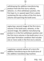
- the void detection technique includes, after forming the layer of the additive manufacturing product via an additive manufacturing process, withdrawing the additive manufacturing product from the first volume of slurry to a first withdrawn position, wherein, in the first withdrawn position, the last-formed layer is spaced apart from a plane containing a top surface of the first volume of slurry and spanning the build zone, and capturing a void image of the first volume of slurry in the build zone, wherein, in the void image, the additive manufacturing product is in the first withdrawn position and the first volume of slurry in the build zone is in a post-layer-formation condition that includes one or more voids in the first volume of slurry.
- the displacement detection technique includes immersing the additive manufacturing product into the second volume of slurry in the build zone, wherein, in a second immersed position, a surface of the last-formed layer is at a layer depth from the top surface of the second slurry volume, and wherein the layer depth is less than a thickness of the second volume of slurry in the build zone in an as-supplied condition, and capturing a displacement image of the second volume of slurry in the build zone, wherein, in the displacement image, the additive manufacturing product is in the second immersed position and the second volume of slurry in the build zone is in a pre-layer-formation condition that includes, relative to the second volume of slurry in an as-supplied condition, a reduced volume of slurry.
- the method to in-situ monitor production of an additive manufacturing product comprises:
- the disclosed methods can be embodied as instructions in non-transitory computer-readable storage medium storing instructions for execution by a process.
- both the void detection technique and displacement detection technique disclosed herein are applicable to additive manufacturing methods that use a transport system for the slurry.
- the displacement detection technique disclosed herein is applicable to additive manufacturing methods that use a vat-style deposition system for the slurry or that use laser curative radiation, for example, SLA and DLP vat-style deposition systems.
- the disclosed method allows for in-situ iterative defect detection, which provides efficiencies in manufacturing (time and material) in that, for example, production of a component can be stopped and a part scrapped, if necessary. Additionally, a detected defect in one manufactured layer can be compensated for, corrected or "healed” by adjustment in a subsequent layer's manufacturing process (and such remediation can be confirmed in-situ before proceeding further with production of the component).
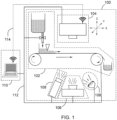
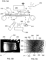
- FIG. 1 is a schematic, block diagram of an additive manufacturing machine 100 in accordance with some embodiments.
- the additive manufacturing machine 100 includes a number of sub-units (also called “components”) communicably coupled to operate the additive manufacturing machine 100 to manufacture an additive manufacturing product.
- Sub-units include, among other things, components 102 to supply a source of material to a build zone, components 104 on which the additive manufacturing product is built, components 106 to deposit or cure the material forming successive layers of the additive manufacturing product, components 108 to image the liquid-based materials during deposition of successive layers of the additive manufacturing product, and components 110 to control the additive manufacturing operation based on digital model data and to in-situ monitor the successive layers of the additive manufacturing product for manufacturing defects.
- Components 110 to control the additive manufacturing operation can be operatively connected to the various sub-units and components by suitable means, such as by digital connections transmitted via wired connections 112 or via wireless connections 114 or via a combination thereof.
- the various sub-units can be separate components or can be combined or otherwise share components.
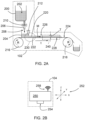
- FIG. 2A schematically illustrates components 102 to supply a source of material to a build zone including a reservoir 200 that contains a supply of liquid-based materials 202, e.g., a slurry.
- the reservoir 200 is in fluid communication to an interim reservoir 204, for example, by tubing 206 having an entrance connected to the reservoir 200 and an exit 208 (directly or indirectly) into the interim reservoir 204.
- a valve 210 controls the flow of the liquid-based materials 202 to the interim reservoir 204.
- the liquid-based materials 202 are formed into a thin, e.g., less than 100 micron, layer 220 of the liquid-based materials 202 on a transporting film 222 by a metering device 212, such as a doctor blade.
- a metering device 212 such as a doctor blade.
- the combination of an adequate volume of liquid-based materials 202 and the structural arrangement of the interim reservoir 204, the metering device 212 and the transporting film 222 provides an adequate head pressure to form a continuous volume of liquid-based materials 202 in the layer 220 on a first side 224 of the transporting film 222 as the transporting film 222 is translated (t) from the deposition zone 230 into and out from the build zone 240.
- the layer 220 of the liquid-based materials 202 on the transporting film 222 has, throughout the length (L) and width (W) of the build zone 240, a thickness (T) relative to the first side 224 of the transporting film 222, e.g., between a top surface 226 oriented toward the build stage 250, such as toward a deposition surface 254 of the build stage 250 (see FIG. 2B ), and a bottom surface 228 oriented toward a curative radiation source 280 such that there is a volume of liquid-based materials 202 in the build zone 240 sufficient to form the to-be-deposited layer of the additive manufacturing product.
- the thickness (T) may be controlled by the metering device 212.
- the layer 220 of the liquid-based materials 202 is, in the as-supplied condition, continuous and has a substantially consistent thickness (T) as formed by the metering device 212.
- the transporting film 222 can be in the form of a continuous belt arranged over rotatable rollers 216, which rotate (R) to move the transporting film 222 in a first direction (M).
- the transporting film 222 can be any suitable material that is sufficiently transmissive to the curative radiation so that the curative radiation functions to solidify or otherwise form the liquid-based material into the layers of the manufactured object, is sufficiently chemically inert to the liquid-based materials 202 (at least within the time frame which the liquid-based materials 202 are in contact with the transporting film 222) to not influence the composition of the additive manufacturing product, and is sufficiently transparent to allow image capture by the image capture device 300.
- the transporting film 222 can be a film of polyethylene terephthalate, more particularly a film of biaxially-oriented polyethylene terephthalate.
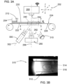
- FIG. 3A schematically illustrates an example of a layer 220 of the liquid-based materials 202 on the transporting film 222 in an as-supplied condition
- FIG. 3B is a corresponding example image of the layer 220 from FIG. 3A as seen from below the transporting film 222, e.g., in the view indicated as A-A', by the image capture device 300.
- the layer 220 is in the as-supplied condition and has a uniform appearance, which indicates a uniform thickness (T) and composition.
- FIG. 2B schematically illustrates components 104 on which the additive manufacturing product is built including a build stage 250.
- the build stage 250 is multi-axial translatable and can be moved in any direction relative to an orthogonally arranged X-axis, Y-axis and Z-axis 252, where the Z-axis is normal to a plane containing the first side 224 of the transporting film 222, the X-axis is parallel to the plane containing the first side 224 of the transporting film 222 and is in a direction parallel to the first direction (M) in which the transporting film 222 moves, and the Y-axis is parallel to the plane containing the first side 224 of the transporting film 222 and is in a direction perpendicular to the first direction (M) in which the transporting film 222 moves.
- the build stage 250 includes a surface on which the additive manufacturing product will be built, e.g., a deposition surface 254.
- the surface 252 is pre-arranged with a base layer of the additive manufacturing product on which subsequent layers will be formed, while in other embodiments, a first layer of the additive manufacturing product is formed directly on the deposition surface 254.
- the deposition surface 254 is a surface of or mounted on the build stage 250; in other figures, such as FIG.
- the build stage 250 is depicted with an in-process additive manufacturing product 10, and the deposition surface 20 is a surface on the in-process additive manufacturing product 10 or, for subsequent layers of the in-process additive manufacturing product 10, the deposition surface 20 will be the outer surface of the in-process additive manufacturing product 10, which is regenerated upon each iterative process to be the most distal surface relative to the deposition surface 254 (in the Z-axis).
- the length (L) and width (W) of the build zone 240 correspond to the X-axis direction and the Y-axis direction and the thickness (T) of layer 220 of the liquid-based materials 202 on the transporting film 222 corresponds to the Z-axis direction.
- the build stage 250 is positioned above the build zone 240 so that the build stage 250 can be translated in the X-axis and Y-axis to a desired position above the volume of liquid-based materials 202 in the build zone 240 and translated in the Z-axis to immerse the deposition surface 254 on which the additive manufacturing product will be built or the deposition surface 20 (depending on the point at which one is in the iterative deposition process) into the volume of liquid-based materials 202 in the build zone 240.
- the build stage 250 (and in particular, the deposition surface 254) is aligned with the curative radiation source 280 along an axis 256.
- the deposition surface 254 (if in an initial deposition layer) or a previously deposited layer of an in-process additive manufacturing product 10 (if in a subsequent or in-process deposition layer) can be immersed into the volume of liquid-based materials 202 in the build zone 240.
- the volume of liquid-based materials 202 in the build zone 240 is in the as-supplied condition consistent with the thickness (T) of the layer 220 of the liquid-based materials 202 as formed by the metering device 212.
- Immersing the deposition surface 254 locates the deposition surface at a layer depth (D L ) (relative to a top surface 226 of the layer 220 of the liquid-based materials 202 in an as-supplied condition).
- the layer depth (D L ) is less than the thickness (T) of the layer 220 of the liquid-based materials 202 in the build zone 240 in an as-supplied condition.
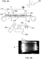
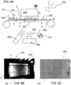
- FIG. 4B is a corresponding image of the layer 220 from FIG. 4A as seen from below the transporting film 222, e.g., in the view indicated as B-B', by the image capture device 300.
- a portion of the volume of the liquid-based materials 202 in the build zone 240 has been displaced.
- the displacement results in a reduced thickness of the liquid-based materials 202 in areas of the layer 220 that correspond to the geometry and other structural features of the deposition surface.
- This displacement is observable (as seen from below the transporting film 222) as a change in appearance in the layer 220 relative to the appearance of the layer 220 in the as-supplied condition (as an example compare FIG. 4B with the image of the as-supplied condition in FIG. 3B ).
- the layer 220 in the region B (outside of region A) is substantially undisturbed and in the as-supplied condition, while the layer 220 in the region A has a change in appearance reflecting the displacement resulting from the immersion of the deposition surface 254.
- the just deposited, in-process additive manufacturing product 10 is withdrawn from the volume of liquid-based materials 202 in the build zone 240.
- the second translation of the build stage 250 in the Z-axis is to a withdrawn position in which the deposition surface 20 of the just-formed layer, e.g., a first layer (L n ) or any subsequent layer (L n+1 ), is spaced apart from the plane containing the top surface 226 of the layer 220 and that spans the build zone 240.
- the transporting film 222 moves in a first direction (M) to transport a new portion of the layer 220 of the liquid-based materials 202 into the build zone 240, the deposition surface 20 of the just-formed layer will not contact a top surface 226 of the layer 220 of the liquid-based materials 202 and will not disturb the as-supplied condition of the layer 220.
- the build stage 250 can include or be operatively connected to a wireless transceiver 258. Although shown in connection with build stage 250, any one or more of the components of additive manufacturing machine 100 can include or be operatively connected via wireless transceivers.
- FIG. 5A schematically illustrates an example of an in-process additive manufacturing product 10 in the withdrawn position and after having been formed while immersed into the volume of liquid-based materials 202 in the build zone 240 and before the transporting film 222 has moved in the first direction (M) to transport a new portion of the layer 220 of the liquid-based materials 202 into the build zone 240
- FIG. 5B is a corresponding image of the layer 220 from FIG. 5A as seen from below the transporting film 222, e.g., in the view indicated as C-C', by the image capture device 300.
- FIG. 5C is a magnified and perspective corrected example of the region P1 in the image in FIG. 5B .
- the layer 220 of the liquid-based materials 202 includes one or more voids 290, that are formed by the liquid-based materials 202 having been formed into the as-deposited layer of the in-process additive manufacturing product 10.
- the voids represent the negative space remaining in the layer 220 of the liquid-based material 202 after a portion of the liquid-based material 202 has been manufactured into the as-deposited layer of the in-process additive manufacturing product 10.
- the pattern 292 of voids 290 is representative of the deposition surface 20 of the just-formed, as-deposited layer on the deposition surface 20 and the in-process additive manufacturing product 10 has been withdrawn from the volume of liquid-based materials 202, e.g., to a withdrawn position.
- Such voids 290 are artifacts of the deposition process and correspond in geometry and other structural features to the just-formed as-deposited layer.
- the image contains a second pattern 292' of voids. This second pattern 292' is due to the image being taken after a prior deposition process. An image taken after a first deposition process would not have a second pattern 292'.
- the process of the first translation of the build stage 250, formation of the first as-deposited layer, the second translation of the build stage 250, and then moving the transporting film 222 to transport a new portion of the layer 220 of the liquid-based materials 202 into the build zone 240 can be iteratively repeated to form multiple as-deposited layers (L 1 , L 2 , .... L n-1 , L n ), where n equals the number of as-deposited layers forming the additive manufacturing product.
- FIG. 2C schematically illustrates components 106 to deposit or cure the material forming successive layers of the additive manufacturing product including a curative radiation source 280.
- the curative radiation source 280 is positioned to project curative radiation 282 through the transporting film 222 and into the layer 220 of the liquid-based materials 202, e.g., the slurry for additive manufacturing, that is located in the build zone 240.
- Any suitable curative radiation source 280 can be used that can cure (or otherwise solidify) the liquid-based materials 202.
- the curative radiation source 280 uses electromagnetic radiation at a specified wavelength that reacts with opto-reactive materials in the liquid-based materials 202. Stereolithography (SL), digital light processing (DLP), and electron-beam-based techniques can be used.
- SL Stereolithography
- DLP digital light processing
- electron-beam-based techniques can be used.
- FIG. 2D schematically illustrates components 108 to image the liquid-based materials during deposition of successive layers of the additive manufacturing product, which include an image capture device 300 and an illumination source 310.
- the image capture device 300 is positioned with a field of view along axis 302 that includes the build zone 240 viewed through the transporting film 222 so as to be capable of capturing images of the liquid-based materials 202 during deposition of successive layers of the additive manufacturing product.
- Such images can include, for example, images of (i) the layer 220 of liquid-based materials 202 in the as-supplied condition, e.g., see FIGS.
- the axis 302 of the field of view of the image capture device 300 may be at an angle ( ⁇ ) to the axis 256 associated with the curative radiation emanating from the curative radiation source 280. The value of the angle ( ⁇ ) is used in image processing and analysis of the various acquired images.
- the image capture device 300 can be in-line with the curative radiation source 280.
- An example image capture device 300 includes a high resolution camera using CCD, CMOS or hyperspectral imaging technology, and having a resolution of 4 megapixel or more and 16 megapixel or less. Although described herein as images, the images can be either still images or video and include digital formats.
- the illumination source 310 is positioned to project visible light 312 toward the layer 220 of liquid-based materials 202 in the build zone 240.
- the illumination source 310 is on the same side of the build zone 240 as the image capture device 300 so that it provides sufficient light to the build zone 240 to allow for image capture of sufficient quality to allow subsequent image analysis.
- FIG. 6 shows an example of registry marks 330 embodied as a pattern of high contrast dots.
- the registry marks 330 allow alignment and correspondence between two different collected images.
- an example collected image can have each pixel assigned a location relative to a coordinate system established by a first axis 332 and a second axis 334 defined relative to the registry marks 330.
- the registry marks 330 also allow triangulation of the image within build window 336 and is used for processing and analysis of the collected images.
- the registry marks 330 in FIG. 6 are shown in an example location on stationary targeting strip 338 and relative to the build window 3346 but other locations can be used.
- the build window 336 is a window corresponding to the build zone 240.
- FIG. 2E schematically illustrates components 110 to control the additive manufacturing operation based on digital model data and to in-situ monitor the successive layers of the additive manufacturing product for manufacturing defects.
- the components 110 include a computer or other control device 350 having one or more processing units (processors or cores), (optionally) one or more network or other communications interfaces, memory including a non-transitory computer readable storage medium, and one or more connections including communication buses and/or wireless transceivers 352 for interconnecting components.
- the connections optionally include circuitry (sometimes called a chipset) that interconnects and controls communications between system components.
- the controller system includes a user interface having a display device 354 and (optionally) a user interface 356, such as a keyboard/mouse or other input device.
- a user interface having a display device 354 and (optionally) a user interface 356, such as a keyboard/mouse or other input device.
- the display device 354 can include a touch-sensitive surface, in which case the display device is a touch-sensitive display.
- FIG. 7A schematically illustrates a subsequent step in the manufacture of an additive manufacturing product.
- the transporting film 222 can be moved in the first direction (M) to transport a new portion of the layer 220 of the liquid-based materials 202 into the build zone 240.
- FIG. 7A schematically illustrates an example of a layer 220 of the liquid-based materials 202 on the transporting film 222 in an as-supplied condition and with the build stage 250 in the withdrawn position.
- FIG. 7B is a corresponding example image of the layer 220 from FIG. 7A as seen from below the transporting film 222, e.g., in the view indicated as D-D', by the image capture device 300.
- the layer 220 is in the as-supplied condition and has a uniform appearance, which indicates a uniform thickness (T) and composition.
- the as-supplied condition for this in-process step should be substantively the same as the as-supplied condition at the beginning of the manufacturing process, e.g., the appearance of the layer 220 in the build zone 240 in the as-supplied condition in the image in FIG. 7B should be substantially the same as the appearance of the layer 220 in the build zone 240 in the as-supplied condition in the image in FIG. 3B (assuming the imaging parameters are consistent).
- the image in FIG. 7B may differ from the image in FIG. 3B by having evidence of the most recent deposition process, such as the pattern 292", which has been transported out of the build zone 240 for the next deposition layer.
- FIG. 7C is a magnified and perspective corrected example of the region P2 in the image in FIG. 7B and showing the pattern 292" of voids.
- the deposition surface 20 of the previously deposited layer of the in-process additive manufacturing product 10 can be immersed into the volume of liquid-based materials 202 in the build zone 240 when in the as-supplied condition consistent with the thickness (T) of the layer 220 of the liquid-based materials 202 as formed by the metering device 212.
- Immersing the deposition surface 20 locates the deposition surface 20 at a layer depth (D L ) (relative to a top surface 226 of the layer 220 of the liquid-based materials 202 in an as-supplied condition).
- the layer depth (D L ) is less than the thickness (T) of the layer 220 of the liquid-based materials 202 in the build zone 240 in an as-supplied condition.
- FIG. 8B is a corresponding image of the layer 220 from FIG. 8A as seen from below the transporting film 222, e.g., in the view indicated as E-E', by the image capture device 300.
- FIG. 8C is a magnified and perspective corrected example of the region P3 in the image in FIG. 8B .
- a portion of the volume of the liquid-based materials 202 in the build zone 240 has been displaced. The displacement results in a reduced thickness of the liquid-based materials 202 in areas of the layer 220 that correspond to the geometry and other structural features of the deposition surface 20.
- This displacement is observable (as seen from below the transporting film 222) as a change in appearance in the layer 220 relative to the appearance of the layer 220 in the as-supplied condition (as an example compare FIGS. 8B and 8C with the images of the as-supplied condition in FIGS. 7B and 7C ).
- the layer 220 in the region D is substantially undisturbed and in the as-supplied condition.
- the displacement in region C forms a pattern 370 that is representative of the deposition surface 20.
- the image in FIGS. 8B and 8C provides information on the surface of the deposition surface 20 that has just been formed in the prior deposition process and before any subsequent deposition process (for example and more generally, information on a first layer (L n ) prior to deposition of a second layer (L n+1 )).
- the portion of the slurry volume between the surface of the first layer (L n ) and the transporting film 222 is thinner than the thickness (T) of the layer 220 in the as-supplied condition.
- this reduced thickness is sufficiently thin that surface features of the surface of the first layer (L n ) can be observed.
- Observable surface features include the geometric shape of the printed part. The surface features can be observed either directly or indirectly.
- the slurry is sufficiently transparent that the surface features of the surface of the first layer (L n ) are observable through thickness T L of the layer 220.
- surface features of the surface of the first layer (L n ) impart characteristics to the slurry that correspond to the surface features.
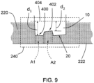
- example surface features are shown including a mesa 400 and a channel 402, both of which are at a distance (d 1 , d 2 respectively) from a reference surface indicated by dashed line 404 (which can be an imaginary reference surface or, for example, the surface of the last deposited layer of the additive manufacturing product 10). Because of the different distances, surfaces of the mesa 400 and of the channel 402 are at different distances relative to the transporting film 222. Thus, the thickness of the layer 220 slurry between the surfaces of the mesa 400 and of the channel 402 are different.
- the different areas A1 and A2 of the slurry have different visual appearances when viewed through the transporting film 222. These different visual appearances correspond to the underlying surfaces and provide a secondary indicia of the surface features. For example, a surface feature such as a channel 402 (or a hole in the in-process additive manufacturing product 10) will result in a thicker slurry between the surface feature and the transporting film 222, which will be observable as a visibly darker or more opaque portion of the slurry.
- a surface feature such as a mesa 400 will result in a thinner slurry between the surface feature and the transporting film 222, which will be observable as a visibly lighter or more transparent portion of the slurry.
- the thinner slurry between the surface feature and the transporting film is sufficiently transparent that that the actual surface features are observable.
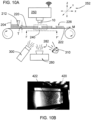
- FIG. 10A schematically illustrates a subsequent step in the manufacture of an additive manufacturing product.
- the just deposited, in-process additive manufacturing product 10 is withdrawn from the volume of liquid-based materials 202 in the build zone 240.
- this second translation of the build stage 250 is in the Z-axis and is to the withdrawn position.
- FIG. 10B is a corresponding image of the layer 220 from FIG. 10A as seen from below the transporting film 222, e.g., in the view indicated as F-F', by the image capture device 300 and showing the pattern 420 of voids 422 resulting from the most recent additive manufacturing deposition process.
- FIGS. 11A to 11F outline an embodiment of a method 500 to in-situ monitor production of an additive manufacturing process.
- the various processes outlined in the steps of the flowchart in FIGS. 11A to 11F can be read and interpreted in connection with the schematics and images in FIGS. 3A-B to 10A-B .
- the additive manufacturing process begins by forming or otherwise providing a surface, e.g., a base surface, on which a first layer (L n ) of the additive manufacturing product 10 will be formed. If the first layer (L n ) of the method 500 is an initial layer of the additive manufacturing product 10, the base surface can be the deposition surface 254 of the build stage 250; if the first layer (L n ) of the method 500 is a subsequent layer of the additive manufacturing product 10, the base surface can be the deposition surface 20 of the just-deposited, prior layer (L n-1 ) of the in-process additive manufacturing product 10.
- a surface e.g., a base surface
- a first portion of the additive manufacturing product 10 is formed in a first deposition step S505, wherein the additive manufacturing product is attached to a build stage 250 of an additive manufacturing machine.
- Forming the first portion can proceed by a process that forms a first layer (L n ) of the additive manufacturing product 10 on the build stage 250 or by a process of forming a subsequent layer (L n+1 ) of the additive manufacturing product 10 onto the deposition surface 20 of the just-deposited prior layer (L n ).
- FIG. 3A schematically illustrates an additive manufacturing machine during a process of supplying a first volume of a slurry for additive manufacturing to a build zone 240 of the additive manufacturing machine.
- a volume of liquid-based materials 202, e.g., slurries, present in an interim reservoir 204 are formed into a thin, e.g., less than 100 micron, layer 220 of the liquid-based materials 202 on a transporting film 222 by a doctor blade 212, which acts as a metering device 212.
- An example thickness of the layer 220 is 30-100 micron, such as 40-80 microns.
- the transporting film 222 is advanced in a direction (M) and causes the layer 220 of liquid-based materials 202 to also move into the build zone 240 below the build stage 250, which is the surface on which the additive manufacturing product 10 is formed.
- FIGS. 3A-B (for an initial layer) schematically illustrate an additive manufacturing machine during a process of capturing an image of the first slurry volume in the build zone 240 and an example image 510 (sometimes referred to herein as a first image of the first slurry volume in the build zone).
- the first image 510 is captured by the image capturing components 108, such as image capture device 300 in conjunction with illumination source 310 (as necessary to provide adequate image quality), and is of a first slurry volume in the build zone 240 in an as-supplied condition.
- the first image 510 of the first slurry volume is taken through the transporting film 222 and shows the bottom surface 228 of the layer 220 of the liquid-based materials 202 that is oriented toward the curative radiation source 280.
- the slurry volume is substantially undisturbed and uniform.
- the first image 510 provides baseline information on layer 220 of the liquid-based materials 202 in the as-supplied condition to be used in subsequent calibration and comparison processes.
- the first image 510 in FIG. 3B shows lighting effects including a lighting gradient (from light to dark as one goes from left to right in the image as shown by arrow 512) and reflections 514 from, for example, the illumination source 310, or from other equipment 516. It is also possible to detect non-uniformity in the slurry, such as from streaks resulting from inadequate layer formation or impurities in the liquid-based materials 202 forming the layer 220 of slurry.
- FIGS. 7A-C illustrate this process for a subsequent layer.
- the method 500 continues and the additive manufacturing product 10 is then immersed S520 into the first slurry volume in the build zone 240 to a first immersed position and a first layer (L n ) is formed on a deposition surface.
- FIGS. 4A-B schematically illustrates this process (for an initial layer).
- the first portion of the additive manufacturing product 20 (or a first portion of the build stage 250 if the initial deposition of the additive manufacturing product 10) is at a first layer depth (D Ln ) from the top surface 226 of the layer 220, which also forms a first slurry volume in the build zone 240.
- the first layer (L n ) is formed S525 on a deposition surface 20 of the first portion from at least a first portion of the first slurry volume located between the deposition surface 20 and the bottom surface of the first slurry volume.
- the first layer (L n ) is formed on the deposition surface 20 by exposing the first slurry volume to curative radiation 282 from the curative radiation source 280 based on parameters in the 3D model or other electronic data source used to operate the additive manufacturing machine to the make the additive manufacturing product. Exposing connects the newly formed material to the deposition surface to form a continuous body. Additionally, the distance between the deposition surface 20 and the bottom surface of the first slurry volume defines a layer thickness (T Ln ) of the first layer (L n ). FIGS. 8A-C illustrate this process for a subsequent layer.
- FIG. 5A schematically illustrates the additive manufacturing product 10 in the withdrawn position.
- the just-formed first layer (L n ) is spaced apart from a plane (P) containing the top surface 226 of the first slurry volume and spanning the build zone 240 (for example and as shown in FIG. 5A , spaced apart from the top surface 226 of the layer 220 by a distance SA).
- Withdrawing places the just-formed first layer (L n ) in a position where no portion of the just-formed first layer (L n ) will be in contact with the layer 220 of liquid-based materials 202 during subsequent movement of the transporting film 222 in direction (M) to move the just-used portion of the layer 220 of liquid-based materials 202 out of the build zone 240 and to move a new portion of the layer 220 of liquid-based materials 202 (such portion being in the as-supplied condition) into the build zone 240.
- withdrawing the additive manufacturing product 10 leaves a series of openings or voids in the layer 220 of liquid-based materials 202 corresponding to the withdrawn material formed into the first layer (L n ).
- the method 500 captures S535 an image of the slurry in this condition (sometimes referred to herein as a second image of the first slurry volume in the build zone).
- Example image 530 is of the first slurry volume in the build zone after the first layer (L n ) has been formed, e.g. in the post-layer-formation condition, and the additive manufacturing product 10 has been repositioned to the withdrawn position.
- the image 530 is captured by the image capturing components 108, such as image capture device 300 in conjunction with illumination source 310 (as necessary to provide adequate image quality), and is of a first slurry volume in the build zone 240 in post-deposition condition.
- the image 530 of the first slurry volume is taken through the transporting film 222 and shows the bottom surface 228 of the layer 220 of the liquid-based materials 202 that is oriented toward the curative radiation source 280.
- Information on the just-formed first layer (L n ) can be inferred from information in the image 530.
- the slurry volume in the build zone includes one or more voids 290. Because of the correspondence to the withdrawn material formed into the first layer (L n ), these voids 290 can be analyzed and correlated to the build quality of the just-formed first layer (L n ) of the in-process additive manufacturing product 10.
- such residual slurry may be indicative of manufacturing defects in the just-formed first layer (L n ), such as corresponding to an area in the just-formed first layer (L n ) that is missing material deposited from the slurry and, therefore, has formed a pore in the body of the just-formed first layer (L n ).
- the presence of pores in the just-formed first layer (L n ) can, over successive deposition processes, lead to porosity in the as-manufactured additive manufacturing product 10.
- the method 500 continues by supplying S540 a volume of a slurry (sometimes referred to herein as a second volume of slurry) for additive manufacturing to the build zone 240 of the additive manufacturing machine.
- a volume of a slurry (sometimes referred to herein as a second volume of slurry) for additive manufacturing to the build zone 240 of the additive manufacturing machine.
- FIG. 7A schematically illustrates an additive manufacturing machine during a process of supplying a second volume of a slurry for additive manufacturing to a build zone 240 of the additive manufacturing machine.
- a volume of liquid-based materials 202, e.g., slurries, present in an interim reservoir 204 are formed into a thin, e.g., less than 100 micron, layer 220 of the liquid-based materials 202 on a transporting film 222 by a doctor blade 212, which acts as a metering device 212.
- An example thickness of the layer 220 is 30-100 micron, alternatively 40-80 microns.
- the transporting film 222 is advanced in a direction (M) and causes a portion of layer 220 of liquid-based materials 202 that is in the as-supplied condition to move into the build zone 240 below the build stage 250.
- advancement of the transporting film 222 in a direction (M) causes the portion of the layer 220 used in the last deposition process (e.g., the portion with voids 290) to move out of the build zone 240.
- layer 220 of the liquid-based materials 202 is recovered from the transporting film 222 and collected, for example, for recirculation to the reservoir 200.
- the method 500 captures S545 an image of the second volume of slurry in the as-supplied condition (sometimes referred to herein as a first image of the second slurry volume in the build zone).
- Example image 550 (see FIG. 7B ) is of the second slurry volume in the build zone in the as-supplied condition. Note that the additive manufacturing product 10 has not yet been in contact with the second slurry volume, and preferably has not been repositioned from the withdrawn position.
- the image 550 is captured by the image capturing components 108, such as image capture device 300 in conjunction with illumination source 310 (as necessary to provide adequate image quality).
- the image 550 of the second slurry volume is taken through the transporting film 222 and shows the bottom surface 228 of the layer 220 of the liquid-based materials 202 that is oriented toward the curative radiation source 280.
- the image 550 one observes an uniform slurry surface with minimal or no visible variation in material appearance on the "fresh" side of the film.
- the image 550 provides baseline information on layer 220 of the liquid-based materials 202 in the as-supplied condition to be used in subsequent calibration and comparison processes.
- FIG. 8A schematically illustrates this process.
- the surface of the first layer (L n ) on which a second layer (L n+1 ) will be deposited is at a second layer depth (D Ln+1 ) from the top surface 226 of the layer 220, which also forms a second slurry volume in the build zone 240.
- D L D L
- Example image 570 is of the second slurry volume in the build zone with the additive manufacturing product 10 immersed into the second slurry volume in the build zone 240 to the second immersed position and prior to forming the second layer (L n+1 ) on the deposition surface.
- the image 570 is captured by the image capturing components 108, such as image capture device 300 in conjunction with illumination source 310 (as necessary to provide adequate image quality).
- the image 570 of the second slurry volume is taken through the transporting film 222 and shows the bottom surface 228 of the layer 220 of the liquid-based materials 202 that is oriented toward the curative radiation source 280.
- the method 500 continues by withdrawing the additive manufacturing product 10 from the second slurry volume to a withdrawn position (see FIG. 10A ).
- the method 500 continues by correcting and then analyzing the captured images.
- the correction removes variations in lighting and surface texture from the second (displacement) image and third (void) image by removing details present in the first (baseline) image.
- image properties of the second image of the first slurry volume e.g., image 530
- the first image of the first slurry volume e.g., image 510
- image properties of the second image of the second slurry volume are corrected S565 based on the first image of the second slurry volume (e.g., image 550) to form a corrected displacement image.
- the as-obtained image can be corrected for triangulation and offset from the axis normal to the bottom surface 228 of the layer 220 (for example using the registry marks 330 as shown and described in connection with FIG.
- optical lens correction which accounts for radial distortion induced by the curvature of the lens
- OpenCV Open Source Computer Vision Library
- Forming the corrected void image proceeds by the following. An example of this process is illustrated by the images in FIGS 12A-C .
- the as-captured image 700 is corrected for perspective and offset to form a first interim corrected image 710.
- the first interim corrected image 710 is then corrected for environmental conditions such as (i) reflections on the surfaces in the field of view, such as any glass surfaces and the surface of the transporting film 222, (ii) variations in coloration of the slurry 202, and (iii) any lighting gradients.
- Such correction can occur by normalizing based on the first image of the first slurry volume 530 (e.g., the "start of layer" image).
- first image of the first slurry volume may also be corrected for perspective and offset, and the corrected first image of the first slurry volume may then be used as the baseline for correcting the void image for environmental conditions.
- the result of the corrections is a corrected void image 720.
- Each layer deposited in an iterative process has at least one corrected void image 720 and at least one corrected displacement image 750, or alternatively, a plurality of corrected void images 720 and a plurality of corrected displacement images 750, which form a collection of corrected images associated with the manufacturing of the additive manufacturing product.
- one corrected void image 720 is paired with one corrected displacement image 750.
- the collection of corrected images are then analyzed using thresholding.
- the thresholding classifies pixels in each image as either “dark” or “light” based on a threshold level applied on a regional basis based on nearest neighbors.
- the threshold range is automatically set by determining the mean and standard deviation of the greyscale or color values of the uncured resin in the image (outside of the build area).
- the pixels in the build area are then classified as either "uncured resin” or "part” based on their difference from the mean.
- the "build area” is determined by masking out the bounding box surrounding the printed part geometry. Because this thresholding requires a greater difference from the mean to be classified as "part,” this thresholding is more conservative for void images (as compared to displacement images) because the contrast is higher.
- Image thresholding is used to classify pixels in the images as either "uncured resin” or "part". The thresholding process determines whether each pixel's data value (generally from 0-255) lies in a particular range. In the displacement images, displaced resin appears as either darker or brighter than the uncured resin slurry, which has a very uniform appearance. Similarly, in the void images, the voids appear darker than the uncured resin slurry, which has a uniform appearance.
- the constants C Lower and C Higher are determined algorithmically based on a displacement image.
- the process for determining the constants C Lower and C Higher crops a full displacement image to a reduced area that is determined by the geometry file and ensures that there will not be any image overlap with any previously built layers.
- cropping results in artifacts from prior processes being outside the cropped area C1, such as the void artifacts 760 to the left of the image in FIG. 14A , while retaining the area to be analyzed within the cropped area C1, such as the area containing displacement artifacts 770 in the cropped image in FIG. 14B .
- Two samples are then taken of the cropped image - a foreground image and a background image, where foreground is the expected printed part and background is uncured, unexposed resin. These two samples are masked out using the expected geometry from the digital model data from, for example, a 3D model or another electronic data source such as a computer-aided design (CAD) model, an Additive Manufacturing File (AMF) file, or a stereolithography contour (SLC) file (usually in sequential layers).
- CAD computer-aided design
- AMF Additive Manufacturing File
- SLC stereolithography contour
- FIG. 14C is an example of a masked image
- FIG. 14E is an example of a pixel value frequency diagram.
- the number of pixels from each sample which are equal to a particular value from 0-255 are counted, and then the total counts are divided into the total number of pixels to provide a frequency value.
- the intersection of the graphed lines for foreground and background frequency determine the upper and lower thresholds for foreground by starting at the peak background value and iterating outwards on each side of the peak background value until the foreground frequency is greater than the background frequency.
- FIG. 14C is an example of a masked image
- FIG. 14E is an example of a pixel value frequency diagram.
- the upper threshold i.e, C Higher
- the lower threshold i.e., C Lower
- this process is done for each color channel separately and, in order to be classified as "foreground,” all three color channels must fall outside the lower and upper thresholds for "background.”
- pixels in the image are processed to be white or black and the analyzed image is converted into a binary image (based on black or white pixels) for further classification and use.
- FIG. 14D is an example of such a converted binary image.
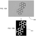
- FIGS. 15A-B are images illustrating the effects of dynamic thresholding for void images.
- a corrected void image 800 is processed by dynamic thresholding resulting in a binary void image 810.
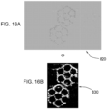
- FIGS. 16A-B are images illustrating the effects of dynamic thresholding for displacement images.
- the corrected displacement image 820 is processed by dynamic thresholding resulting in a binary displacement image 830.
- the general equations and methods for thresholding can be applied using color-scale in place of gray-scale, in which case the general equations and methods are applied to each of the three color bands (red, green, and blue).
- the binary void image and binary displacement image for each layer formed in the additive manufacturing process are then compared S570 to a binary expected image for that layer.
- the binary expected layer is based on a reference binary image.
- the reference binary image can be generated based on a CAD model or other input and corresponds to the input used to control the manufacturing of the layer by the additive manufacturing machine.
- the binary expected image has a higher resolution than any of the images captured by the image capture device 300.
- the binary expected image can be based on sampling of actual additive manufacturing products.
- 17A-D are example images used in the comparison process, including binary void image 850, binary displacement image 860, the binary expected image 870 associated with the layer corresponding to the binary void image 850 and the binary displacement image 860, and the comparison image 880 resulting from the pixel-to-pixel comparison 890.
- the comparison 890 the binary image from both resin displacement and void detection are compared to the expected geometry at a pixel level. Small connected regions within the manufactured part are compared to provide a regional "confidence level.”
- the "confidence level” is the ratio of pixels in a segment that are classified as “part” to the total number of expected pixels. If this ratio is sufficiently high (i.e. at least 50%, but this can change based on material and empirical experience), the entire segment is judged to be present. This method is used particularly when the pixel classifier is tuned to minimize false "part” detections, which will misclassify a fraction of the true "part” pixels as “uncured resin.”
- Suitable segmentation methods include “by-contour” and "tiled.”
- the "by-contour” method treats each contiguous region of expected part as a single segment. Because delamination defects have only rarely been observed to occur over partial sections of "contours,” this method is suitable for detecting delamination defects.
- the tiled method breaks the expected part into square tiles, which enables the detection of partially adhered areas or smaller defects.
- Confidence levels can be implemented based on thresholding or other suitable techniques, such as computer vision methods or neural networks.
- the binary expected image typically includes one or more contiguous regions.
- a percentage of coverage in the corrected void image can be quantified based on a pixel-level comparison within each contiguous region.
- the presence (or absence) of a manufacturing defect can be indicated based on a percentage of coverage below (or above) a threshold void image value in a portion of the additive manufacturing product corresponding to the contiguous region of the corrected void image.
- the threshold void image value is 97% and a percentage of coverage less than 97% correlates to the presence of a manufacturing defect and a percentage of coverage equal to or greater than 97% correlates to the absence of a manufacturing defect.
- a percentage of coverage in the corrected void image can be quantified based on a pixel-level comparison within each contiguous region.
- the presence (or absence) of a manufacturing defect can be identified S555 based on a percentage of coverage below (or above) a threshold displacement image value in a portion of the additive manufacturing product corresponding to the contiguous region of the corrected void image.
- the threshold displacement image value is 97% and a percentage of coverage less than 97% correlates to the presence of a manufacturing defect and a percentage of coverage equal to or greater than 97% correlates to the absence of a manufacturing defect.
- both the threshold void image value and the threshold displacement image value must be above a threshold to correlate to the absence of a manufacturing defect.
- the threshold void image value being above the threshold is sufficient to correlate to the absence of a manufacturing defect, even if the threshold displacement image value is below the threshold.
- the threshold void image value being below the threshold is sufficient to correlate to the presence of a manufacturing defect, even if the threshold displacement image value is above the threshold.
- the regions labeled as F1 and F2 represent regions of the layer where the comparison resulted in a fail indication.
- a fail indication corresponds to a lack of deposited material, a failure to cure, a delamination, or some other failure in the additive manufacturing of that location in the layer.
- a plurality of comparison images can be collected and assembled into a 3D model corresponding to the as-manufactured additive manufacturing product or corresponding to at least a portion of the as-manufactured additive manufacturing product.
- FIG. 18A is an example collection of comparison images 880 (including fail regions F1 and F2) and
- FIG. 18B is an assembled 3D rendering 900 of the comparison images 880. In the 3D rendering 900, the fail regions F1 and F2 are visible.
- FIG. 19 is a photograph of an additive manufacturing prototype sample corresponding to the assembled 3D rendering 900 in FIG. 18B and clearly shows the fail regions F1 and F2.
- the ability to identify and visualize fail regions, such as F1 and F2, allows for failure detection.
- the failure detection can be remotely monitored and can be in-situ during the manufacturing process of post-manufacturing, such as when qualifying a manufactured part during quality controls.
- the disclosed method also provides a method to detect pores within the additive manufacturing product.
- the presence of residual slurry within the perimeter of the void 290 may be indicative of manufacturing defects in the just-formed first layer (L n ). These manufacturing defects can be, for example, a pore in the body of the just-formed first layer (L n ), that leads to porosity in the just-formed first layer (L n ) and, over successive deposition processes, leads to porosity in the as-manufactured additive manufacturing product 10.
- the analysis of a corrected void image can optionally detect residual that can become porous in printed layers.
- any slurry detached from and not contiguous with the layer 220 within the perimeter of the void 290 that is not part of the expected geometry of the additive manufacturing product can be assumed to be evidence of a pore.
- This approach works regardless of the flow of the slurry itself (which may cover varying areas of the contour depending on viscosity) because any isolated drop of slurry cannot have been the result of flow after the deposition event.
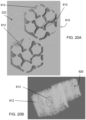
- FIG. 20A is a magnified, corrected void image 910 and shows a plurality of residual slurry 912 within the perimeter of the void 290.
- the residual slurry 912 is detached from and not contiguous with the layer 220.
- Image processing identifies residual slurry 912, typically in the form of drops, with a 30 micron resolution and determines which residual slurry 912 are disconnected from any potential slurry flow In embodiments of the process to classify the "pores", an image is classified as either "resin” or "void” using the threshold method previously described herein.
- FIG. 20B is an image showing an example of a 3D defect model 920 containing true pores 922.
- the true pores identified by this process enables quantification of total part density and identification of potential weak points in the as-manufactured part.
- the high degree of precision of identifying pores by this process has been confirmed by forensic analysis of an as-manufactured part.
- a 3D defect model of an as-manufactured part was created and a region of expected high porosity exposed, e.g., by slicing, and examined using a microscope. Pore locations observed using the microscope matched the pore location in the 3D defect model.
- the components 110 to control the additive manufacturing operation based on digital model data and to in-situ monitor the successive layers of the additive manufacturing product for manufacturing defects is embodied in a computer system or computer-aided machine, such as a computer controlled additive manufacturing machine.
- the computer system or computer portion of a computer-aided machine can be a general purpose computer, a special purpose computer, or a server that includes, among other things, non-transitory computer-readable storage medium including instructions for operating and controlling the additive manufacturing machine 100 and an electronic data source, such as a computer-aided design (CAD) model or an Additive Manufacturing File (AMF) file or a stereolithography contour (SLC) file (usually in sequential layers) related to the additive manufacturing product 10.
- CAD computer-aided design
- AMF Additive Manufacturing File
- SLC stereolithography contour
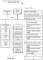
- FIG. 21 is a block diagram illustrating an additive manufacturing machine (AMM) controller 1000 in accordance with some embodiments.
- the AMM controller 1000 typically includes one or more processing units (processors or cores) 1002, (optionally) one or more network or other communications interfaces 1004, memory 1006, and one or more wired or wireless connections 1008 for interconnecting these components.
- processing units processors or cores
- network or other communications interfaces 1004
- memory 1006 for interconnecting these components.
- wired or wireless connections 1008 for interconnecting these components.
- such connections may include communication buses that optionally includes circuitry (sometimes called a chipset) that interconnects and controls communications between system components.
- the components may communicate wirelessly using wireless transceivers.
- the AMM controller system 1000 includes a user interface 1010.
- the user interface 1010 may include a display device 1012 and optionally includes an input device 1016, such as a keyboard/ mouse, a trackpad, and/or input buttons.
- the display device 1012 includes a touch-sensitive surface 1014, in which case the display device is a touch-sensitive display.
- the connections 1008 of the AMM controller system 1000 also operatively connects to and interfaces with the various sub-units that are communicably coupled to operate the additive manufacturing machine 100 to manufacture an additive manufacturing product.
- connections 1008 of the controller system 1000 are operatively connected to and interface with components 102 to supply a source of material to a build zone (such as components associated with storing, supplying and transporting the slurry 202), components 104 on which the additive manufacturing product is built (such as build stage 250), components 106 to deposit or cure the material forming successive layers of the additive manufacturing product (such as curative radiation source 280), components 108 to image the liquid-based materials during deposition of successive layers of the additive manufacturing product (such as image capture device 300 and illumination source 310).
- a build zone such as components associated with storing, supplying and transporting the slurry 202
- components 104 on which the additive manufacturing product is built such as build stage 250
- components 106 to deposit or cure the material forming successive layers of the additive manufacturing product such as curative radiation source 280
- components 108 to image the liquid-based materials during deposition of successive layers of the additive manufacturing product such as image capture device 300 and illumination source 310.
- the memory 1006 includes high-speed random-access memory, such as DRAM, SRAM, DDR RAM, or other random-access solid-state memory devices, and may include non-volatile memory, such as one or more magnetic disk storage devices, optical disk storage devices, flash memory devices, and/or other non-volatile solid-state storage devices.
- the memory 1006 includes one or more storage devices remotely located from the processor(s) 1002.
- the memory 1006, or alternatively the non-volatile memory device(s) within the memory 1006, includes a non-transitory computer-readable storage medium.
- the memory 1006 or the computer-readable storage medium of the memory 1006 stores instructions for executing the method(s) described herein (e.g., by a processor).
- the memory stores the following programs, modules, and data structures, or a subset or superset thereof:
- Each of the above identified modules corresponds to a set of executable instructions for performing one or more functions as described above and/or in the methods described in this application (e.g., the additive manufacturing methods, the computer-implemented methods, and other information processing methods described herein).
- these modules e.g., sets of instructions
- the memory 1006 stores a subset of the modules and data structures identified above.
- the memory 1006 stores additional modules and data structures not described above.
- Suitable additive manufacturing equipment can be utilized that can accommodate the specific requirements for the materials to be used in the manufacture of the component (such as chemical resistance), the specific requirements for utilization of the equipment itself (such as specific atmospheric or vacuum requirements), as well as can accommodate the size and geometry of the manufactured component.
- suitable additive manufacturing equipment include SLA and DLP machines, electron-beam-based additive manufacturing equipment, and DLP stereolithographic equipment, any one of which can be modified or adapted for specific requirements
- Example methods of additive manufacturing can comprise providing a design of a component to be manufactured to a controller of an additive manufacturing equipment. Such a design can be incorporated into an additive manufacturing protocol.
- the additive manufacturing protocol can be developed and/or adapted for use in any suitable additive manufacturing process.
- suitable additive manufacturing processes are disclosed in ISO/ASTM52900-15, which defines categories of additive manufacturing processes, including: binder jetting, directed energy deposition, material extrusion, material jetting, powder bed fusion, sheet lamination, and photopolymerization.
- the contents of ISO/ASTM52900-15 are mentioned.
- Sterolithography is a form of additive manufacturing using photopolymerization processes.
- stereolithographic additive manufacturing techniques include photoinitiation from exposure to ultraviolet radiation or beta radiation.
- the ultraviolet radiation is generated in a digital light processor (DLP) or in a stereolithography apparatus (SLA).
- DLP digital light processor
- SLA stereolithography apparatus
- the beta radiation is generated in electron-beam (EBeam) equipment or electron irradiation (EBI) equipment.
- EBeam electron-beam
- EBI electron irradiation
- a supply volume of the slurry composition is established, such as a bath or reservoir.
- a base portion of a green body of the component is then formed by curing a portion of the slurry composition that is in contact with a movable base of the additive manufacturing equipment.
- a base portion can be pre-fabricated prior to the initiation of the additive manufacturing process.
- Additional portions of the green body of the component are formed on a layer-by-layer basis by, first, curing a portion of the slurry composition that is in contact with the base portion to form a first layer of a green body and then, second, curing a portion of the slurry composition that is in contact with the prior deposition layer of the green body to form the additional portions while translating the movable base relative to an interface between a surface of the supply volume and the most recently formed additional portion of the green body.
- the translation of the movable base is typically in accordance with the design of the component and as directed by the additive manufacturing protocol.
- translating the movable base relative to the interface between the surface of the supply volume and the most recently formed additional portion of the green body has an X-axis resolution and a Y-axis resolution of 50 microns or better and has a Z-axis resolution of 20 microns or better.
- each additional portion of the green body of the component formed on the layer-by-layer basis has a thickness of at least 25 microns, alternatively 25 microns to 50 microns.
- the additive manufacturing process or slurry compositions can be adjusted to correct, mitigate, or compensate for the defect and/or deviation.
- constituents of the composition can be adjusted and varied (either the materials chemistry or the amounts of constituents).
- one or more parameters of the additive manufacturing technique can be adjusted and varied, such as movement of the build stage (spatially and temporally), temperatures associated with deposition, sequencing of steps, etc.
- process parameters that can be adjusted include parameters such as: increasing the temperature of the reservoir to higher temperatures, reducing viscosity, creating a more uniform layer thickness, adjusting the delay before irradiation to allow for proper leveling of an additive manufacturing print layer, adjusting movement speeds to allow for mitigation of hydraulic bearing forces and print window delamination, providing multiple exposures per layer to limit scattering and increase depth of cure, and continuously varying intensity exposures (movies) to optimize desired properties.
- design parameters that can be adjusted include parameters such as: altering the design for thin geometries that are below the capabilities to be printed, increasing/removing pores which are too small and can become occluded during exposure by scattering, adding drain or cleaning holes to the part to aid in trapped slurry removal, combining gyroid and lattice forms to support delicate geometry with structurally and neutronically useful material.
- the adjustments in composition and/or parameters can occur independently or in combination. Also, the adjustments in composition and/or parameters can be implemented in subsequent iterations of an in-progress iterative deposition process or in a subsequent iterative deposition process.
- the adjustment of a composition of the slurry or of a parameter of the additive manufacturing technique can be conducted to determine the effect of varying such composition/parameters.
- Information on such cause and effect can be developed and used in subsequent iterations of the in-progress iterative deposition process or in a subsequent iterative deposition process.
- additive manufacturing processes include any technologies that build 3D objects by adding material on a layer-upon-layer basis.
- the disclosed methods can be applied for the manufacture of nuclear fission reactor structures and ancillary equipment.
- An example of a suitable additive manufacturing process utilizes 3-D printing of a metal alloy, such as a molybdenum-containing metal alloy, Zircaloy-4 or Hastelloy X, to form the noted structural features such as the cladding.
- a fissionable nuclear fuel composition and/or the thermal transfer agent and/or the moderator materials and/or poisons used as part of the nuclear fission reactor structure can be included within the integral, unitary structure when suitable multi-material, additive manufacturing processes with multiple metals within the feedstock are employed. If the molten metal is not included in the additive manufacturing process, the additive manufacturing process can be paused, a volume of molten metal placed into the fuel cavity (either in liquid or solid form) and the additive manufacturing process continued to complete the structure of the closed chamber.
- Other alloys that can be used for fission reactor structures and ancillary equipment when employing suitable multi-material, additive manufacturing processes with multiple metals within the feedstock include: steel alloys, zirconium alloys, and molybdenum-tungsten alloys (for the cladding and/or for the containment structure); beryllium alloys (for the reflector); and stainless steel (for the containment structure). Even when not manufactured by an additive manufacturing process, the above materials can be used in manufacturing the various features and structures of such fission reactors and ancillary equipment.
- Additive manufacturing techniques disclosed herein can include the additional steps of: (a) predictive and causal analytics, (b) in-situ monitoring combined with machine vision and accelerated processing during the layer-by-layer fabrication of the structure, (c) automated analysis combined with a machine learning component, and (d) virtual inspection of a digital representation of the as-built structure.
- additive manufacturing technology can create complex geometries and, when coupled with in-situ sensors, machine vision imagery, and artificial intelligence, allows for tuning of the manufacturing quality as the components are built on a layer-by-layer additive basis (often, these layers are on the scale of 50 microns) and provides predictive quality assurance for the manufacture of such reactors and structures.
- Example materials can be used for additively manufacturing components of nuclear fission reactors and ancillary equipment For cladding, typically a corrosion-resistant material with low absorption cross section for thermal neutrons is used.
- Example materials include Zircaloy or steel, although other materials may be used if suitable to the reactor conditions, such as metallic and ceramic systems (Be, C, Mg, Zr, O, and Si), as well as compositions including molybdenum, tungsten, rhenium, tantalum, hafnium and alloys thereof, including carbides.
- the composition can be high-assay low-enriched uranium (HALEU) which has a U 235 assay above 5 percent but below 20 percent or can be highly enriched uranium (HEU) with uranium that is 20% or more U 235 .
- HALEU high-assay low-enriched uranium
- HEU highly enriched uranium
- a suitable fissionable nuclear fuel composition applicable to the disclosed fuel element structure includes uranium oxide (UO 2 ) that is less than 20% enriched, uranium with 10 wt.% molybdenum (U-10Mo), uranium nitride (UN), and other stable fissionable fuel compounds. Burnable poisons may also be included.
- the fissionable nuclear fuel composition is in the form of a ceramic material (cermet), such as UO 2 with W or Mo and UN with W or Mo.
- a thermal transfer agent such as a salt or metal that will be molten at operating temperatures, can be included in the fuel element structure to improve thermal coupling between the fuel composition body and the cladding body. Additionally, a thermal transfer agent can occupy cracks or other defects in the fuel element structure (whether originally present or developing during reactor operation) to promote thermal coupling.
- Suitable molten metals for inclusion in the disclosed nuclear propulsion fission reactor structure and to be included in the fuel element structure to provide thermal transfer contact includes sodium (Na), sodium-potassium (NaK), potassium (K), and iron (Fe).
- first and second are used herein to describe various elements, these elements should not be limited by these terms. These terms are used only to distinguish one element from another. For example, a first image could be termed a second image, and, similarly, a second image could be termed a first image, without departing from the scope of the various described embodiments. The first image and the second image are both images, but they are not the same image.
- stages that are not order dependent may be reordered and other stages may be combined or broken out. While some reordering or other groupings are specifically mentioned, others will be obvious to those of ordinary skill in the art, so the ordering and groupings presented herein are not an exhaustive list of alternatives. Moreover, it should be recognized that the stages could be implemented in hardware, firmware, software, or any combination thereof.
Landscapes
- Engineering & Computer Science (AREA)
- Chemical & Material Sciences (AREA)
- Materials Engineering (AREA)
- Manufacturing & Machinery (AREA)
- Physics & Mathematics (AREA)
- Optics & Photonics (AREA)
- Mechanical Engineering (AREA)
- Computer Vision & Pattern Recognition (AREA)
- General Physics & Mathematics (AREA)
- Theoretical Computer Science (AREA)
- Quality & Reliability (AREA)
- Analytical Chemistry (AREA)
- Automation & Control Theory (AREA)
- Plasma & Fusion (AREA)
- Health & Medical Sciences (AREA)
- Toxicology (AREA)
- Multimedia (AREA)
- Geometry (AREA)
- Image Processing (AREA)
Claims (13)
- Computerimplementiertes Verfahren zur In-situ-Überwachung einer Produktion eines Additivfertigungprodukts (10), wobei das Verfahren Folgendes umfasst:Erhalten (S515) eines ersten Grundlinienbildes eines Schlickers zur additiven Fertigung in einem ersten Volumen des Schlickers in einer Bauzone (240) einer Additivfertigungmaschine (100);Bilden (S525) einer Schicht des Additivfertigungprodukts (10) aus dem Schlicker über einen additiven Fertigungsprozess;Detektieren eines oder mehrerer Defekte in der Schicht unter Verwendung einer Hohlraumdetektionstechnik;Erhalten eines zweiten Grundlinienbildes des Schlickers in einem zweiten Volumen des Schlickers in der Bauzone (240) der Additivfertigungmaschine (100);Detektieren eines oder mehrerer Defekte in der Schicht unter Verwendung einer Verdrängungsdetektionstechnik; undAnalysieren einer Ausgabe der Hohlraumdetektionstechnik und der Verdrängungsdetektionstechnik, um eine Anwesenheit oder eine Abwesenheit eines Fertigungsdefekts in dem Additivfertigungprodukt (10) zu identifizieren,wobei die Hohlraumdetektionstechnik Folgendes beinhaltet:nach dem Bilden (S525) der Schicht des Additivfertigungprodukts über den additiven Fertigungsprozess, Zurückziehen (S530) des Additivfertigungprodukts (10) aus dem ersten Volumen des Schlickers in eine erste, zurückgezogene Position, wobei in der ersten, zurückgezogenen Position eine zuletzt gebildete Schicht von eine Ebene beabstandet ist, die eine obere Oberfläche (226) des ersten Volumens des Schlickers enthält und die Bauzone (240) überspannt; undErfassen (S535) eines Hohlraumbildes des ersten Volumens des Schlickers in der Bauzone, wobei sich in dem Hohlraumbild das Additivfertigungprodukt (10) in der ersten, zurückgezogenen Position befindet und sich das erste Volumen des Schlickers in der Bauzone (240) in einem Nachschichtbildungszustand befindet, der einen oder mehrere Hohlräume in dem ersten Volumen des Schlickers beinhaltet,wobei das Analysieren der Ausgabe der Hohlraumdetektionstechnik einen Vergleich auf Pixelebene eines binären Hohlraumbildes, das aus dem Hohlraumbild gebildet wird, und eines binären erwarteten Bildes beinhaltet, das mit der Schicht assoziiert ist, die dem binären Hohlraumbild entspricht,wobei die Verdrängungsdetektionstechnik Folgendes beinhaltet:Eintauchen (S550) des Additivfertigungprodukts (10) in das zweite Volumen des Schlickers in der Bauzone (240), wobei in einer zweiten, eingetauchten Position eine Oberfläche der zuletzt gebildeten Schicht in einer Schichttiefe von der oberen Oberfläche des zweiten Schlickervolumens ist, und wobei die Schichttiefe geringer als eine Dicke des zweiten Volumens des Schlickers in der Bauzone in einem Wie-bereitgestellt-Zustand ist; undErfassen (S555) eines Verdrängungsbildes des zweiten Volumens des Schlickers in der Bauzone (240), wobei sich in dem Verdrängungsbild das Additivfertigungprodukt in der zweiten, eingetauchten Position befindet und sich das zweite Volumen des Schlickers in der Bauzone (240) in einem Vorschichtbildungszustand befindet, der relativ zu dem zweiten Volumen des Schlickers in einem Wiebereitgestellt-Zustand ein reduziertes Volumen des Schlickers beinhaltet, undwobei das Analysieren der Ausgabe der Verdrängungsdetektionstechnik einen Vergleich auf Pixelebene eines binären Verdrängungsbildes, das aus dem Verdrängungsbild gebildet wird, und eines binären erwarteten Bildes beinhaltet, das mit der Schicht assoziiert ist, die dem binären Verdrängungsbild entspricht.
- Verfahren nach Anspruch 1, wobei die Additivfertigungmaschine (100) Folgendes beinhaltet:einen Transportfilm, wobei eine erste Seite des Transportfilms den Schlicker zur additiven Fertigung stützt und den Schlicker in die Bauzone (240) hinein oder aus dieser heraus transportiert,eine Aushärtungsstrahlungsquelle, die zum Projizieren von Aushärtungsstrahlung durch den Transportfilm und in den Schlicker hinein, der sich in der Bauzone (240) befindet, positioniert ist,eine Beleuchtungsquelle, die zum Projizieren von sichtbarem Licht in den Schlicker in der Bauzone (240) hinein positioniert ist, undeine Bilderfassungsvorrichtung, die mit einem Sichtfeld positioniert ist, das die Bauzone (240) bei Betrachtung durch den Transportfilm beinhaltet.
- Verfahren nach Anspruch 1 oder Anspruch 2, wobei das binäre erwartete Bild ein oder mehrere zusammenhängende Gebiete beinhaltet, wobei der Vergleich auf Pixelebene in jedem zusammenhängenden Gebiet stattfindet, und wobei das Vergleichen des binären Hohlraumbildes mit dem binären erwarteten Bild einen Deckungsprozentsatz in dem binären Hohlraumbild basierend auf dem Vergleich auf Pixelebene innerhalb jedes zusammenhängenden Gebiets quantifiziert.
- Verfahren nach Anspruch 3, wobei eine Abwesenheit eines Fertigungsdefekts dadurch angegeben wird, dass der Deckungsprozentsatz oberhalb eines Schwellenhohlraumbildwertes in einem Teil des Additivfertigungsprodukts (10) liegt, der dem zusammenhängenden Gebiet des binären Hohlraumbildes entspricht.
- Verfahren nach Anspruch 1 oder Anspruch 2, wobei das binäre erwartete Bild ein oder mehrere zusammenhängende Gebiete beinhaltet, wobei der Vergleich auf Pixelebene in jedem zusammenhängenden Gebiet stattfindet, und wobei das Vergleichen des binären Verdrängungsbildes mit dem binären erwarteten Bild einen Deckungsprozentsatz in dem binären Verdrängungsbild basierend auf dem Vergleich auf Pixelebene innerhalb jedes zusammenhängenden Gebiets quantifiziert.
- Verfahren nach Anspruch 5, wobei eine Abwesenheit eines Fertigungsdefekts dadurch angegeben wird, dass der Deckungsprozentsatz oberhalb eines Schwellenverdrängungsbildwertes in einem Teil des Additivfertigungsprodukts (10) liegt, der dem zusammenhängenden Gebiet des binären Verdrängungsbildes entspricht.
- Verfahren nach Anspruch 1 oder Anspruch 2, wobei das binäre erwartete Bild ein oder mehrere zusammenhängende Gebiete beinhaltet,wobei der Vergleich auf Pixelebene in jedem zusammenhängenden Gebiet stattfindet,wobei das Vergleichen des binären Hohlraumbildes mit dem binären erwarteten Bild einen ersten Deckungsprozentsatz in dem binären Hohlraumbild basierend auf dem Vergleich auf Pixelebene innerhalb jedes zusammenhängenden Gebiets quantifiziert, undwobei das Vergleichen des binären Verdrängungsbildes mit dem binären erwarteten Bild einen zweiten Deckungsprozentsatz in dem binären Verdrängungsbild basierend auf dem Vergleich auf Pixelebene innerhalb jedes zusammenhängenden Gebiets quantifiziert.
- Verfahren nach Anspruch 7, wobei für das zusammenhängende Gebiet des binären Hohlraumbildes und das zusammenhängende Gebiet des binären Verdrängungsbildes, die demselben Teil des Additivfertigungsprodukts (10) entsprechen, eine Abwesenheit eines Fertigungsdefekts in dem Teil des Additivfertigungsprodukts (10) dadurch angegeben wird, dass der erste Deckungsprozentsatz oberhalb eines Schwellenhohlraumbildwertes liegt und der zweite Deckungsprozentsatz unterhalb eines zweiten Schwellenverdrängungsbildwertes liegt.
- Verfahren nach Anspruch 7, wobei für das zusammenhängende Gebiet des binären Hohlraumbildes und das zusammenhängende Gebiet des binären Verdrängungsbildes, die demselben Teil des Additivfertigungsprodukts (10) entsprechen, eine Anwesenheit eines Fertigungsdefekts in dem Teil des Additivfertigungsprodukts dadurch angegeben wird, dass der erste Deckungsprozentsatz unterhalb eines Schwellenhohlraumbildwertes liegt und der zweite Deckungsprozentsatz oberhalb eines zweiten Schwellenverdrängungsbildwertes liegt.
- Verfahren nach Anspruch 1 oder Anspruch 2,wobei das binäre erwartete Bild ein oder mehrere zusammenhängende Gebiete beinhaltet, wobei der Vergleich auf Pixelebene in jedem zusammenhängenden Gebiet stattfindet, und wobei das Vergleichen des binären Hohlraumbildes mit dem binären erwarteten Bild einen Deckungsprozentsatz in dem binären Hohlraumbild basierend auf dem Vergleich auf Pixelebene innerhalb jedes zusammenhängenden Gebiets quantifiziert, undwobei eine Abwesenheit eines Fertigungsdefekts dadurch angegeben wird, dass der Deckungsprozentsatz oberhalb eines Schwellenhohlraumbildwertes in einem Teil des Additivfertigungsprodukts liegt, der dem zusammenhängenden Gebiet des binären Hohlraumbildes entspricht.
- Verfahren nach einem vorhergehenden Anspruch, wobei der Fertigungsdefekt einen Haftungsdefekt beinhaltet, bei dem Material von dem ersten Volumen des Schlickers nicht an dem Additivfertigungsprodukt (10) gehaftet hat.
- Nichtflüchtiges computerlesbares Speicherungsmedium, das Anweisungen umfasst, die bei Ausführung durch einen Computer den Computer zum Ausführen der folgenden Schritte veranlassen:Erhalten (S515) eines ersten Grundlinienbildes eines Schlickers zur additiven Fertigung in einem ersten Volumen des Schlickers in einer Bauzone (240) einer Additivfertigungmaschine (100);Bilden (S525) einer Schicht des Additivfertigungprodukts (10) aus dem Schlicker über einen additiven Fertigungsprozess;Detektieren eines oder mehrerer Defekte in der Schicht unter Verwendung einer Hohlraumdetektionstechnik;Erhalten eines zweiten Grundlinienbildes des Schlickers in einem zweiten Volumen des Schlickers in der Bauzone (240) der Additivfertigungmaschine (100);Detektieren eines oder mehrerer Defekte in der Schicht unter Verwendung einer Verdrängungsdetektionstechnik; undAnalysieren einer Ausgabe der Hohlraumdetektionstechnik und der Verdrängungsdetektionstechnik, um eine Anwesenheit oder eine Abwesenheit eines Fertigungsdefekts in dem Additivfertigungprodukt (10) zu identifizieren,wobei die Hohlraumdetektionstechnik Folgendes beinhaltet:nach dem Bilden (S525) der Schicht des Additivfertigungprodukts aus dem Schlicker über den additiven Fertigungsprozess, Zurückziehen (S530) des Additivfertigungprodukts (10) aus dem ersten Volumen des Schlickers in eine erste, zurückgezogene Position, wobei in der ersten, zurückgezogenen Position eine zuletzt gebildete Schicht von eine Ebene beabstandet ist, die eine obere Oberfläche (226) des ersten Volumens des Schlickers enthält und die Bauzone (240) überspannt; undErfassen (S535) eines Hohlraumbildes des ersten Volumens des Schlickers in der Bauzone, wobei sich in dem Hohlraumbild das Additivfertigungprodukt (10) in der ersten, zurückgezogenen Position befindet und sich das erste Volumen des Schlickers in der Bauzone (240) in einem Nachschichtbildungszustand befindet, der einen oder mehrere Hohlräume in dem ersten Volumen des Schlickers beinhaltet,wobei das Analysieren der Ausgabe der Hohlraumdetektionstechnik einen Vergleich auf Pixelebene eines binären Hohlraumbildes, das aus dem Hohlraumbild gebildet wird, und eines binären erwarteten Bildes beinhaltet, das mit der Schicht assoziiert ist, die dem binären Hohlraumbild entspricht,wobei die Verdrängungsdetektionstechnik Folgendes beinhaltet:Eintauchen (S550) des Additivfertigungprodukts (10) in das zweite Volumen des Schlickers in der Bauzone (240), wobei in einer zweiten, eingetauchten Position eine Oberfläche der zuletzt gebildeten Schicht in einer Schichttiefe von der oberen Oberfläche des zweiten Schlickervolumens ist, und wobei die Schichttiefe geringer als eine Dicke des zweiten Volumens des Schlickers in der Bauzone in einem Wie-bereitgestellt-Zustand ist; undErfassen (S555) eines Verdrängungsbildes des zweiten Volumens des Schlickers in der Bauzone (240), wobei sich in dem Verdrängungsbild das Additivfertigungprodukt in der zweiten, eingetauchten Position befindet und sich das zweite Volumen des Schlickers in der Bauzone (240) in einem Vorschichtbildungszustand befindet, der relativ zu dem zweiten Volumen des Schlickers in einem Wiebereitgestellt-Zustand ein reduziertes Volumen des Schlickers beinhaltet, undwobei das Analysieren der Ausgabe der Verdrängungsdetektionstechnik einen Vergleich auf Pixelebene eines binären Verdrängungsbildes, das aus dem Verdrängungsbild gebildet wird, und eines binären erwarteten Bildes beinhaltet, das mit der Schicht assoziiert ist, die dem binären Verdrängungsbild entspricht.
- Nichtflüchtiges computerlesbares Speicherungsmedium nach Anspruch 12, wobei die Additivfertigungsmaschine (100) Folgendes beinhaltet:einen Transportfilm, wobei eine erste Seite des Transportfilms den Schlicker zur additiven Fertigung stützt und den Schlicker in die Bauzone (240) hinein oder aus dieser heraus transportiert,eine Aushärtungsstrahlungsquelle, die zum Projizieren von Aushärtungsstrahlung durch den Transportfilm und in den Schlicker hinein, der sich in der Bauzone (240) befindet, positioniert ist,eine Beleuchtungsquelle, die zum Projizieren von sichtbarem Licht in den Schlicker in der Bauzone (240) hinein positioniert ist, undeine Bilderfassungsvorrichtung, die mit einem Sichtfeld positioniert ist, das die Bauzone (240) bei Betrachtung durch den Transportfilm beinhaltet.
Priority Applications (1)
| Application Number | Priority Date | Filing Date | Title |
|---|---|---|---|
| EP25157388.7A EP4530069A3 (de) | 2019-11-27 | 2020-11-20 | Erkennung von harzhaftungsfehlern |
Applications Claiming Priority (3)
| Application Number | Priority Date | Filing Date | Title |
|---|---|---|---|
| US201962941183P | 2019-11-27 | 2019-11-27 | |
| US16/951,543 US11760005B2 (en) | 2019-11-27 | 2020-11-18 | Resin adhesion failure detection |
| PCT/US2020/061411 WO2021108233A2 (en) | 2019-11-27 | 2020-11-20 | Resin adhesion failure detection |
Related Child Applications (2)
| Application Number | Title | Priority Date | Filing Date |
|---|---|---|---|
| EP25157388.7A Division-Into EP4530069A3 (de) | 2019-11-27 | 2020-11-20 | Erkennung von harzhaftungsfehlern |
| EP25157388.7A Division EP4530069A3 (de) | 2019-11-27 | 2020-11-20 | Erkennung von harzhaftungsfehlern |
Publications (4)
| Publication Number | Publication Date |
|---|---|
| EP4065290A2 EP4065290A2 (de) | 2022-10-05 |
| EP4065290A4 EP4065290A4 (de) | 2024-01-17 |
| EP4065290B1 true EP4065290B1 (de) | 2025-03-19 |
| EP4065290C0 EP4065290C0 (de) | 2025-03-19 |
Family
ID=76130678
Family Applications (2)
| Application Number | Title | Priority Date | Filing Date |
|---|---|---|---|
| EP25157388.7A Pending EP4530069A3 (de) | 2019-11-27 | 2020-11-20 | Erkennung von harzhaftungsfehlern |
| EP20891503.3A Active EP4065290B1 (de) | 2019-11-27 | 2020-11-20 | Harzhaftungs-fehlerdetektion |
Family Applications Before (1)
| Application Number | Title | Priority Date | Filing Date |
|---|---|---|---|
| EP25157388.7A Pending EP4530069A3 (de) | 2019-11-27 | 2020-11-20 | Erkennung von harzhaftungsfehlern |
Country Status (5)
| Country | Link |
|---|---|
| US (2) | US11760005B2 (de) |
| EP (2) | EP4530069A3 (de) |
| JP (2) | JP7741352B2 (de) |
| KR (1) | KR20220108787A (de) |
| WO (1) | WO2021108233A2 (de) |
Families Citing this family (15)
| Publication number | Priority date | Publication date | Assignee | Title |
|---|---|---|---|---|
| EP4301544A4 (de) * | 2021-03-01 | 2025-01-29 | Baker Hughes Oilfield Operations LLC | Anomaliedetektion in der generativen fertigung mittels schmelzpoolüberwachung sowie zugehörige vorrichtungen und systeme |
| IT202100022145A1 (it) * | 2021-08-20 | 2023-02-20 | Dws Srl | Sistema e metodo per la stampa stereolitografica. |
| WO2023049690A1 (en) | 2021-09-21 | 2023-03-30 | Abilene Christian University | Stabilizing face ring joint flange and assembly thereof |
| WO2023064488A1 (en) * | 2021-10-14 | 2023-04-20 | Align Technology, Inc. | Recoating system |
| US12208577B2 (en) | 2021-10-14 | 2025-01-28 | Align Technology, Inc. | Recoating system with reduced resin evaporation |
| WO2023164569A1 (en) * | 2022-02-23 | 2023-08-31 | Align Technology, Inc. | Control systems for additive manufacturing and associated methods |
| US20240021327A1 (en) * | 2022-07-12 | 2024-01-18 | BWXT Advanced Technologies LLC | Heat pipe fuel element and fission reactor incorporating same, particularly having phyllotaxis spacing pattern of heat pipe fuel elements, and method of manufacture |
| CN115366409B (zh) * | 2022-08-08 | 2025-03-14 | 西安铂力特增材技术股份有限公司 | 多材料增材制造设备及多材料增材制造方法 |
| US12562289B2 (en) | 2023-01-20 | 2026-02-24 | Abilene Christian University | Fission product trap for salt pipe and pump shaft seals and methods of use thereof |
| KR20240127642A (ko) | 2023-02-16 | 2024-08-23 | 주식회사 휴비츠 | 레진의 사용량을 측정하는 3d 프린터 |
| US20250083394A1 (en) * | 2023-02-27 | 2025-03-13 | Howmedica Osteonics Corp. | Additive Manufacturing Layer Defect Identification and Analysis Using Mask Template |
| US12249434B2 (en) | 2023-03-31 | 2025-03-11 | Abilene Christian University | Thermal expansion support system and methods of use thereof |
| EP4481259A1 (de) * | 2023-06-22 | 2024-12-25 | Leuze electronic GmbH + Co. KG | Überwachungsvorrichtung |
| US12012827B1 (en) | 2023-09-11 | 2024-06-18 | Natura Resources LLC | Nuclear reactor integrated oil and gas production systems and methods of operation |
| US12500006B2 (en) | 2023-12-05 | 2025-12-16 | Natura Resources LLC | Deployment method and systems for molten salt reactors |
Family Cites Families (8)
| Publication number | Priority date | Publication date | Assignee | Title |
|---|---|---|---|---|
| US7424818B2 (en) | 2005-10-20 | 2008-09-16 | Boeing Company | Ultrasonic inspection reference standard for porous composite materials |
| JP2007269007A (ja) | 2006-03-08 | 2007-10-18 | Ngk Insulators Ltd | スラリー塗布装置、及びスラリー塗布欠陥検査装置 |
| US10792868B2 (en) * | 2015-09-09 | 2020-10-06 | Carbon, Inc. | Method and apparatus for three-dimensional fabrication |
| US10719929B2 (en) | 2015-11-16 | 2020-07-21 | Materialise N.V. | Error detection in additive manufacturing processes |
| US20180104742A1 (en) | 2016-10-18 | 2018-04-19 | General Electric Company | Method and system for thermographic inspection of additive manufactured parts |
| US10234848B2 (en) | 2017-05-24 | 2019-03-19 | Relativity Space, Inc. | Real-time adaptive control of additive manufacturing processes using machine learning |
| JP2019104981A (ja) | 2017-12-14 | 2019-06-27 | キヤノン株式会社 | 三次元造形装置および三次元造形物の製造方法 |
| JP7287742B2 (ja) | 2018-01-22 | 2023-06-06 | ウルトラ セーフ ニュークリア コーポレーション | 原子炉システム用の複合減速材 |
-
2020
- 2020-11-18 US US16/951,543 patent/US11760005B2/en active Active
- 2020-11-20 KR KR1020227020908A patent/KR20220108787A/ko active Pending
- 2020-11-20 WO PCT/US2020/061411 patent/WO2021108233A2/en not_active Ceased
- 2020-11-20 JP JP2022531007A patent/JP7741352B2/ja active Active
- 2020-11-20 EP EP25157388.7A patent/EP4530069A3/de active Pending
- 2020-11-20 EP EP20891503.3A patent/EP4065290B1/de active Active
-
2023
- 2023-07-31 US US18/228,077 patent/US12023857B2/en active Active
-
2024
- 2024-05-29 JP JP2024087129A patent/JP7748162B2/ja active Active
Also Published As
| Publication number | Publication date |
|---|---|
| WO2021108233A3 (en) | 2021-06-24 |
| EP4530069A3 (de) | 2025-06-25 |
| US12023857B2 (en) | 2024-07-02 |
| EP4065290C0 (de) | 2025-03-19 |
| WO2021108233A2 (en) | 2021-06-03 |
| EP4530069A2 (de) | 2025-04-02 |
| JP2024109915A (ja) | 2024-08-14 |
| CA3158229A1 (en) | 2021-06-03 |
| EP4065290A2 (de) | 2022-10-05 |
| US11760005B2 (en) | 2023-09-19 |
| JP2023505057A (ja) | 2023-02-08 |
| JP7748162B2 (ja) | 2025-10-02 |
| EP4065290A4 (de) | 2024-01-17 |
| JP7741352B2 (ja) | 2025-09-18 |
| US20230373155A1 (en) | 2023-11-23 |
| KR20220108787A (ko) | 2022-08-03 |
| US20210170676A1 (en) | 2021-06-10 |
Similar Documents
| Publication | Publication Date | Title |
|---|---|---|
| EP4065290B1 (de) | Harzhaftungs-fehlerdetektion | |
| Yeung et al. | Part geometry and conduction-based laser power control for powder bed fusion additive manufacturing | |
| Gobert et al. | Application of supervised machine learning for defect detection during metallic powder bed fusion additive manufacturing using high resolution imaging. | |
| US20150177158A1 (en) | Operational performance assessment of additive manufacturing | |
| EP4494787A1 (de) | Systeme und verfahren zur komprimierung, verwaltung und analyse von downbeam-kameradaten für eine additive maschine | |
| US20150165683A1 (en) | Operational performance assessment of additive manufacturing | |
| CN112677487B (zh) | 3d打印的控制方法、控制系统及3d打印设备 | |
| Zhang et al. | Influence of spattering on in-process layer surface roughness during laser powder bed fusion | |
| US12499533B2 (en) | Computer-implemented, adapted anomaly detection method for powder-bed-based additive manufacturing | |
| CN113103587B (zh) | 3d打印的控制方法、控制系统及3d打印设备 | |
| Moshiri et al. | Performance evaluation of in-situ near-infrared melt pool monitoring during laser powder bed fusion | |
| WO2025106456A1 (en) | Unsupervised 3d modeling and geometric measurement of parts built with powder bed fusion-based additive manufacturing | |
| WO2020176733A1 (en) | Sensor based build segmentation in additive manufacturing | |
| Lee et al. | Autonomous in-situ defect detection and correction in additive-lathe 3D printing process using variational autoencoder model | |
| CA3158229C (en) | Resin adhesion failure detection | |
| Armin et al. | Defect detection in 3D printing: A review of image processing and machine vision techniques | |
| Lafirenza et al. | In-process evaluation of layer defects and surface topography on material extruded parts through a novel point cloud functional analysis | |
| CN117078586B (zh) | 一种面向dlp 3d打印过程中树脂填充不足的缺陷检测与修复方法 | |
| CN120334229A (zh) | 打印缺陷检测方法、装置、打印机及存储介质 | |
| Bugatti et al. | Unlocking New In-Situ Defect Detection Capabilities in Additive Manufacturing with Machine Learning and a Recoater-Based Imaging Architecture | |
| Ahar et al. | Accelerated monitoring of powder bed fusion additive manufacturing via high-throughput imaging and low-latency machine learning | |
| KR102926410B1 (ko) | 분말 도포 상태에 따른 불량을 예측할 수 있는 금속 3d 프린터 및 금속 3d 프린팅 방법 | |
| US20250083394A1 (en) | Additive Manufacturing Layer Defect Identification and Analysis Using Mask Template | |
| Bonato et al. | Comparison of postprocess X-ray computed tomography and in-process optical measurements for defects evaluation in additively manufactured parts | |
| Shekh et al. | Machine Learning-Enabled In-Situ Defect Detection in Extrusion-Based Additive Manufacturing: A Step Toward Qualification and Certification |
Legal Events
| Date | Code | Title | Description |
|---|---|---|---|
| STAA | Information on the status of an ep patent application or granted ep patent |
Free format text: STATUS: THE INTERNATIONAL PUBLICATION HAS BEEN MADE |
|
| PUAI | Public reference made under article 153(3) epc to a published international application that has entered the european phase |
Free format text: ORIGINAL CODE: 0009012 |
|
| STAA | Information on the status of an ep patent application or granted ep patent |
Free format text: STATUS: REQUEST FOR EXAMINATION WAS MADE |
|
| 17P | Request for examination filed |
Effective date: 20220524 |
|
| AK | Designated contracting states |
Kind code of ref document: A2 Designated state(s): AL AT BE BG CH CY CZ DE DK EE ES FI FR GB GR HR HU IE IS IT LI LT LU LV MC MK MT NL NO PL PT RO RS SE SI SK SM TR |
|
| DAV | Request for validation of the european patent (deleted) | ||
| DAX | Request for extension of the european patent (deleted) | ||
| REG | Reference to a national code |
Ref country code: DE Ref legal event code: R079 Free format text: PREVIOUS MAIN CLASS: B05D0007220000 Ipc: G06T0007000000 Ref document number: 602020048122 Country of ref document: DE |
|
| A4 | Supplementary search report drawn up and despatched |
Effective date: 20231214 |
|
| RIC1 | Information provided on ipc code assigned before grant |
Ipc: B05C 13/02 20060101ALI20231208BHEP Ipc: B05D 7/22 20060101ALI20231208BHEP Ipc: G06T 7/254 20170101ALI20231208BHEP Ipc: G06T 7/00 20170101AFI20231208BHEP |
|
| GRAP | Despatch of communication of intention to grant a patent |
Free format text: ORIGINAL CODE: EPIDOSNIGR1 |
|
| STAA | Information on the status of an ep patent application or granted ep patent |
Free format text: STATUS: GRANT OF PATENT IS INTENDED |
|
| RIC1 | Information provided on ipc code assigned before grant |
Ipc: B33Y 50/02 20150101ALI20241025BHEP Ipc: B33Y 10/00 20150101ALI20241025BHEP Ipc: B29C 64/393 20170101ALI20241025BHEP Ipc: B29C 64/223 20170101ALI20241025BHEP Ipc: B29C 64/129 20170101ALI20241025BHEP Ipc: B22F 12/90 20210101ALI20241025BHEP Ipc: B22F 10/85 20210101ALI20241025BHEP Ipc: G06T 7/254 20170101ALI20241025BHEP Ipc: G06T 7/00 20170101AFI20241025BHEP |
|
| INTG | Intention to grant announced |
Effective date: 20241119 |
|
| RAP3 | Party data changed (applicant data changed or rights of an application transferred) |
Owner name: BWXT ADVANCED TECHNOLOGIES LLC |
|
| GRAS | Grant fee paid |
Free format text: ORIGINAL CODE: EPIDOSNIGR3 |
|
| GRAA | (expected) grant |
Free format text: ORIGINAL CODE: 0009210 |
|
| STAA | Information on the status of an ep patent application or granted ep patent |
Free format text: STATUS: THE PATENT HAS BEEN GRANTED |
|
| AK | Designated contracting states |
Kind code of ref document: B1 Designated state(s): AL AT BE BG CH CY CZ DE DK EE ES FI FR GB GR HR HU IE IS IT LI LT LU LV MC MK MT NL NO PL PT RO RS SE SI SK SM TR |
|
| REG | Reference to a national code |
Ref country code: GB Ref legal event code: FG4D |
|
| REG | Reference to a national code |
Ref country code: CH Ref legal event code: EP |
|
| REG | Reference to a national code |
Ref country code: IE Ref legal event code: FG4D |
|
| REG | Reference to a national code |
Ref country code: DE Ref legal event code: R096 Ref document number: 602020048122 Country of ref document: DE |
|
| U01 | Request for unitary effect filed |
Effective date: 20250319 |
|
| U07 | Unitary effect registered |
Designated state(s): AT BE BG DE DK EE FI FR IT LT LU LV MT NL PT RO SE SI Effective date: 20250325 |
|
| PG25 | Lapsed in a contracting state [announced via postgrant information from national office to epo] |
Ref country code: RS Free format text: LAPSE BECAUSE OF FAILURE TO SUBMIT A TRANSLATION OF THE DESCRIPTION OR TO PAY THE FEE WITHIN THE PRESCRIBED TIME-LIMIT Effective date: 20250619 |
|
| PG25 | Lapsed in a contracting state [announced via postgrant information from national office to epo] |
Ref country code: NO Free format text: LAPSE BECAUSE OF FAILURE TO SUBMIT A TRANSLATION OF THE DESCRIPTION OR TO PAY THE FEE WITHIN THE PRESCRIBED TIME-LIMIT Effective date: 20250619 |
|
| PG25 | Lapsed in a contracting state [announced via postgrant information from national office to epo] |
Ref country code: HR Free format text: LAPSE BECAUSE OF FAILURE TO SUBMIT A TRANSLATION OF THE DESCRIPTION OR TO PAY THE FEE WITHIN THE PRESCRIBED TIME-LIMIT Effective date: 20250319 |
|
| PG25 | Lapsed in a contracting state [announced via postgrant information from national office to epo] |
Ref country code: GR Free format text: LAPSE BECAUSE OF FAILURE TO SUBMIT A TRANSLATION OF THE DESCRIPTION OR TO PAY THE FEE WITHIN THE PRESCRIBED TIME-LIMIT Effective date: 20250620 |
|
| PG25 | Lapsed in a contracting state [announced via postgrant information from national office to epo] |
Ref country code: SM Free format text: LAPSE BECAUSE OF FAILURE TO SUBMIT A TRANSLATION OF THE DESCRIPTION OR TO PAY THE FEE WITHIN THE PRESCRIBED TIME-LIMIT Effective date: 20250319 |
|
| PG25 | Lapsed in a contracting state [announced via postgrant information from national office to epo] |
Ref country code: ES Free format text: LAPSE BECAUSE OF FAILURE TO SUBMIT A TRANSLATION OF THE DESCRIPTION OR TO PAY THE FEE WITHIN THE PRESCRIBED TIME-LIMIT Effective date: 20250319 |
|
| PG25 | Lapsed in a contracting state [announced via postgrant information from national office to epo] |
Ref country code: PL Free format text: LAPSE BECAUSE OF FAILURE TO SUBMIT A TRANSLATION OF THE DESCRIPTION OR TO PAY THE FEE WITHIN THE PRESCRIBED TIME-LIMIT Effective date: 20250319 |
|
| PG25 | Lapsed in a contracting state [announced via postgrant information from national office to epo] |
Ref country code: CZ Free format text: LAPSE BECAUSE OF FAILURE TO SUBMIT A TRANSLATION OF THE DESCRIPTION OR TO PAY THE FEE WITHIN THE PRESCRIBED TIME-LIMIT Effective date: 20250319 |
|
| PG25 | Lapsed in a contracting state [announced via postgrant information from national office to epo] |
Ref country code: SK Free format text: LAPSE BECAUSE OF FAILURE TO SUBMIT A TRANSLATION OF THE DESCRIPTION OR TO PAY THE FEE WITHIN THE PRESCRIBED TIME-LIMIT Effective date: 20250319 |
|
| PG25 | Lapsed in a contracting state [announced via postgrant information from national office to epo] |
Ref country code: IS Free format text: LAPSE BECAUSE OF FAILURE TO SUBMIT A TRANSLATION OF THE DESCRIPTION OR TO PAY THE FEE WITHIN THE PRESCRIBED TIME-LIMIT Effective date: 20250719 |
|
| U20 | Renewal fee for the european patent with unitary effect paid |
Year of fee payment: 6 Effective date: 20251126 |
|
| PGFP | Annual fee paid to national office [announced via postgrant information from national office to epo] |
Ref country code: GB Payment date: 20251127 Year of fee payment: 6 |
|
| PLBE | No opposition filed within time limit |
Free format text: ORIGINAL CODE: 0009261 |
|
| STAA | Information on the status of an ep patent application or granted ep patent |
Free format text: STATUS: NO OPPOSITION FILED WITHIN TIME LIMIT |
|
| REG | Reference to a national code |
Ref country code: CH Ref legal event code: L10 Free format text: ST27 STATUS EVENT CODE: U-0-0-L10-L00 (AS PROVIDED BY THE NATIONAL OFFICE) Effective date: 20260128 |
|
| 26N | No opposition filed |
Effective date: 20251222 |