EP4065262B1 - Statischer mischer und generatives fertigungssystem damit - Google Patents
Statischer mischer und generatives fertigungssystem damit Download PDFInfo
- Publication number
- EP4065262B1 EP4065262B1 EP20829746.5A EP20829746A EP4065262B1 EP 4065262 B1 EP4065262 B1 EP 4065262B1 EP 20829746 A EP20829746 A EP 20829746A EP 4065262 B1 EP4065262 B1 EP 4065262B1
- Authority
- EP
- European Patent Office
- Prior art keywords
- mixing
- static mixer
- alternatively
- blade
- housing
- Prior art date
- Legal status (The legal status is an assumption and is not a legal conclusion. Google has not performed a legal analysis and makes no representation as to the accuracy of the status listed.)
- Active
Links
- 230000003068 static effect Effects 0.000 title claims description 133
- 238000004519 manufacturing process Methods 0.000 title claims description 43
- 239000000654 additive Substances 0.000 title claims description 35
- 230000000996 additive effect Effects 0.000 title claims description 31
- 238000002156 mixing Methods 0.000 claims description 413
- 239000012530 fluid Substances 0.000 claims description 38
- 238000010276 construction Methods 0.000 claims description 27
- 238000004891 communication Methods 0.000 claims description 7
- 239000000203 mixture Substances 0.000 description 209
- 229920001296 polysiloxane Polymers 0.000 description 183
- 239000010410 layer Substances 0.000 description 157
- 238000000034 method Methods 0.000 description 81
- 229920005989 resin Polymers 0.000 description 72
- 239000011347 resin Substances 0.000 description 72
- 239000000463 material Substances 0.000 description 61
- 239000003054 catalyst Substances 0.000 description 57
- 150000003961 organosilicon compounds Chemical class 0.000 description 55
- 238000007711 solidification Methods 0.000 description 50
- 230000008023 solidification Effects 0.000 description 50
- -1 steels Chemical class 0.000 description 43
- 230000008569 process Effects 0.000 description 39
- 238000007639 printing Methods 0.000 description 38
- BASFCYQUMIYNBI-UHFFFAOYSA-N platinum Chemical group [Pt] BASFCYQUMIYNBI-UHFFFAOYSA-N 0.000 description 36
- 238000006459 hydrosilylation reaction Methods 0.000 description 31
- 229910052751 metal Inorganic materials 0.000 description 28
- 239000002184 metal Substances 0.000 description 28
- 238000001125 extrusion Methods 0.000 description 23
- 125000003342 alkenyl group Chemical group 0.000 description 20
- 150000002894 organic compounds Chemical class 0.000 description 19
- 239000002002 slurry Substances 0.000 description 19
- 239000003795 chemical substances by application Substances 0.000 description 18
- 229920000642 polymer Polymers 0.000 description 18
- 238000010146 3D printing Methods 0.000 description 16
- 125000002887 hydroxy group Chemical group [H]O* 0.000 description 15
- 239000007788 liquid Substances 0.000 description 15
- 150000001875 compounds Chemical class 0.000 description 14
- 125000004435 hydrogen atom Chemical group [H]* 0.000 description 14
- 238000010438 heat treatment Methods 0.000 description 13
- 229920002050 silicone resin Polymers 0.000 description 13
- 238000009833 condensation Methods 0.000 description 12
- 230000005494 condensation Effects 0.000 description 12
- 230000008021 deposition Effects 0.000 description 12
- 238000001816 cooling Methods 0.000 description 11
- 230000036961 partial effect Effects 0.000 description 11
- 239000000843 powder Substances 0.000 description 11
- 238000002844 melting Methods 0.000 description 10
- XUIMIQQOPSSXEZ-UHFFFAOYSA-N Silicon Chemical group [Si] XUIMIQQOPSSXEZ-UHFFFAOYSA-N 0.000 description 9
- 239000000919 ceramic Substances 0.000 description 9
- 125000004122 cyclic group Chemical group 0.000 description 9
- 230000008018 melting Effects 0.000 description 9
- 125000005375 organosiloxane group Chemical group 0.000 description 9
- 229920005992 thermoplastic resin Polymers 0.000 description 9
- 239000002826 coolant Substances 0.000 description 8
- 239000000178 monomer Substances 0.000 description 8
- 229910052697 platinum Inorganic materials 0.000 description 8
- HRGDZIGMBDGFTC-UHFFFAOYSA-N platinum(2+) Chemical compound [Pt+2] HRGDZIGMBDGFTC-UHFFFAOYSA-N 0.000 description 8
- 239000000758 substrate Substances 0.000 description 8
- KDLHZDBZIXYQEI-UHFFFAOYSA-N Palladium Chemical compound [Pd] KDLHZDBZIXYQEI-UHFFFAOYSA-N 0.000 description 7
- 239000011230 binding agent Substances 0.000 description 7
- 239000007795 chemical reaction product Substances 0.000 description 7
- 125000000524 functional group Chemical group 0.000 description 7
- 230000007246 mechanism Effects 0.000 description 7
- 150000001282 organosilanes Chemical class 0.000 description 7
- 150000003254 radicals Chemical class 0.000 description 7
- 125000004432 carbon atom Chemical group C* 0.000 description 6
- 238000006243 chemical reaction Methods 0.000 description 6
- 229920001971 elastomer Polymers 0.000 description 6
- 238000005516 engineering process Methods 0.000 description 6
- 125000001495 ethyl group Chemical group [H]C([H])([H])C([H])([H])* 0.000 description 6
- 125000001183 hydrocarbyl group Chemical group 0.000 description 6
- 239000007787 solid Substances 0.000 description 6
- 229920001187 thermosetting polymer Polymers 0.000 description 6
- XLYOFNOQVPJJNP-UHFFFAOYSA-N water Substances O XLYOFNOQVPJJNP-UHFFFAOYSA-N 0.000 description 6
- 229920000426 Microplastic Polymers 0.000 description 5
- 239000004952 Polyamide Substances 0.000 description 5
- 229910020447 SiO2/2 Inorganic materials 0.000 description 5
- 229910020485 SiO4/2 Inorganic materials 0.000 description 5
- 239000011203 carbon fibre reinforced carbon Substances 0.000 description 5
- 239000000806 elastomer Substances 0.000 description 5
- 239000011953 free-radical catalyst Substances 0.000 description 5
- 230000006870 function Effects 0.000 description 5
- 239000003999 initiator Substances 0.000 description 5
- 125000002496 methyl group Chemical group [H]C([H])([H])* 0.000 description 5
- 150000001451 organic peroxides Chemical class 0.000 description 5
- 229920002647 polyamide Polymers 0.000 description 5
- 229920000728 polyester Polymers 0.000 description 5
- 230000002829 reductive effect Effects 0.000 description 5
- 238000007142 ring opening reaction Methods 0.000 description 5
- 239000004593 Epoxy Substances 0.000 description 4
- XYFCBTPGUUZFHI-UHFFFAOYSA-N Phosphine Chemical compound P XYFCBTPGUUZFHI-UHFFFAOYSA-N 0.000 description 4
- 239000004642 Polyimide Substances 0.000 description 4
- 229910020487 SiO3/2 Inorganic materials 0.000 description 4
- 230000008901 benefit Effects 0.000 description 4
- 238000005253 cladding Methods 0.000 description 4
- 230000000295 complement effect Effects 0.000 description 4
- 239000002131 composite material Substances 0.000 description 4
- 239000003431 cross linking reagent Substances 0.000 description 4
- 230000000694 effects Effects 0.000 description 4
- 239000003822 epoxy resin Substances 0.000 description 4
- 239000000945 filler Substances 0.000 description 4
- 239000007789 gas Substances 0.000 description 4
- 150000002978 peroxides Chemical class 0.000 description 4
- 229920000548 poly(silane) polymer Polymers 0.000 description 4
- 229920000647 polyepoxide Polymers 0.000 description 4
- 229920001721 polyimide Polymers 0.000 description 4
- 150000004756 silanes Chemical class 0.000 description 4
- 239000002904 solvent Substances 0.000 description 4
- 239000000126 substance Substances 0.000 description 4
- 238000004804 winding Methods 0.000 description 4
- OXBLVCZKDOZZOJ-UHFFFAOYSA-N 2,3-Dihydrothiophene Chemical compound C1CC=CS1 OXBLVCZKDOZZOJ-UHFFFAOYSA-N 0.000 description 3
- 239000004971 Cross linker Substances 0.000 description 3
- 239000004698 Polyethylene Substances 0.000 description 3
- 239000004743 Polypropylene Substances 0.000 description 3
- KJTLSVCANCCWHF-UHFFFAOYSA-N Ruthenium Chemical compound [Ru] KJTLSVCANCCWHF-UHFFFAOYSA-N 0.000 description 3
- BLRPTPMANUNPDV-UHFFFAOYSA-N Silane Chemical compound [SiH4] BLRPTPMANUNPDV-UHFFFAOYSA-N 0.000 description 3
- 125000000304 alkynyl group Chemical group 0.000 description 3
- 229910045601 alloy Inorganic materials 0.000 description 3
- 239000000956 alloy Substances 0.000 description 3
- 150000001412 amines Chemical class 0.000 description 3
- 238000000149 argon plasma sintering Methods 0.000 description 3
- 230000008859 change Effects 0.000 description 3
- 238000010168 coupling process Methods 0.000 description 3
- 238000005859 coupling reaction Methods 0.000 description 3
- 230000003247 decreasing effect Effects 0.000 description 3
- 238000013461 design Methods 0.000 description 3
- 238000010894 electron beam technology Methods 0.000 description 3
- 125000003700 epoxy group Chemical group 0.000 description 3
- KCNQYEYKVSGPMZ-UHFFFAOYSA-N hydroxysilane silane Chemical compound [SiH4].O[SiH3] KCNQYEYKVSGPMZ-UHFFFAOYSA-N 0.000 description 3
- RAXXELZNTBOGNW-UHFFFAOYSA-N imidazole Natural products C1=CNC=N1 RAXXELZNTBOGNW-UHFFFAOYSA-N 0.000 description 3
- 239000004615 ingredient Substances 0.000 description 3
- 238000007641 inkjet printing Methods 0.000 description 3
- 125000005358 mercaptoalkyl group Chemical group 0.000 description 3
- 150000002739 metals Chemical class 0.000 description 3
- 238000012986 modification Methods 0.000 description 3
- 230000004048 modification Effects 0.000 description 3
- 229920000573 polyethylene Polymers 0.000 description 3
- 229920001155 polypropylene Polymers 0.000 description 3
- 125000001436 propyl group Chemical group [H]C([*])([H])C([H])([H])C([H])([H])[H] 0.000 description 3
- 229910052710 silicon Inorganic materials 0.000 description 3
- 239000010703 silicon Substances 0.000 description 3
- 239000002356 single layer Substances 0.000 description 3
- 238000005245 sintering Methods 0.000 description 3
- 125000003396 thiol group Chemical group [H]S* 0.000 description 3
- 125000000391 vinyl group Chemical group [H]C([*])=C([H])[H] 0.000 description 3
- 229920002554 vinyl polymer Polymers 0.000 description 3
- VYXHVRARDIDEHS-UHFFFAOYSA-N 1,5-cyclooctadiene Chemical compound C1CC=CCCC=C1 VYXHVRARDIDEHS-UHFFFAOYSA-N 0.000 description 2
- 239000004912 1,5-cyclooctadiene Substances 0.000 description 2
- IJGRMHOSHXDMSA-UHFFFAOYSA-N Atomic nitrogen Chemical compound N#N IJGRMHOSHXDMSA-UHFFFAOYSA-N 0.000 description 2
- VTYYLEPIZMXCLO-UHFFFAOYSA-L Calcium carbonate Chemical compound [Ca+2].[O-]C([O-])=O VTYYLEPIZMXCLO-UHFFFAOYSA-L 0.000 description 2
- JOYRKODLDBILNP-UHFFFAOYSA-N Ethyl urethane Chemical compound CCOC(N)=O JOYRKODLDBILNP-UHFFFAOYSA-N 0.000 description 2
- UFHFLCQGNIYNRP-UHFFFAOYSA-N Hydrogen Chemical compound [H][H] UFHFLCQGNIYNRP-UHFFFAOYSA-N 0.000 description 2
- XEEYBQQBJWHFJM-UHFFFAOYSA-N Iron Chemical compound [Fe] XEEYBQQBJWHFJM-UHFFFAOYSA-N 0.000 description 2
- PXHVJJICTQNCMI-UHFFFAOYSA-N Nickel Chemical compound [Ni] PXHVJJICTQNCMI-UHFFFAOYSA-N 0.000 description 2
- 239000004696 Poly ether ether ketone Substances 0.000 description 2
- 239000004962 Polyamide-imide Substances 0.000 description 2
- 239000004721 Polyphenylene oxide Substances 0.000 description 2
- 239000004734 Polyphenylene sulfide Substances 0.000 description 2
- 229910020388 SiO1/2 Inorganic materials 0.000 description 2
- HCHKCACWOHOZIP-UHFFFAOYSA-N Zinc Chemical compound [Zn] HCHKCACWOHOZIP-UHFFFAOYSA-N 0.000 description 2
- 239000002253 acid Substances 0.000 description 2
- 125000003647 acryloyl group Chemical group O=C([*])C([H])=C([H])[H] 0.000 description 2
- 125000002015 acyclic group Chemical group 0.000 description 2
- 239000000853 adhesive Substances 0.000 description 2
- 230000001070 adhesive effect Effects 0.000 description 2
- 125000003545 alkoxy group Chemical group 0.000 description 2
- 125000003282 alkyl amino group Chemical group 0.000 description 2
- 125000000217 alkyl group Chemical group 0.000 description 2
- AZDRQVAHHNSJOQ-UHFFFAOYSA-N alumane Chemical class [AlH3] AZDRQVAHHNSJOQ-UHFFFAOYSA-N 0.000 description 2
- 125000003118 aryl group Chemical group 0.000 description 2
- 125000000484 butyl group Chemical group [H]C([*])([H])C([H])([H])C([H])([H])C([H])([H])[H] 0.000 description 2
- 230000008878 coupling Effects 0.000 description 2
- 238000005520 cutting process Methods 0.000 description 2
- 230000007423 decrease Effects 0.000 description 2
- 230000003111 delayed effect Effects 0.000 description 2
- PZPGRFITIJYNEJ-UHFFFAOYSA-N disilane Chemical compound [SiH3][SiH3] PZPGRFITIJYNEJ-UHFFFAOYSA-N 0.000 description 2
- 239000006185 dispersion Substances 0.000 description 2
- 238000001035 drying Methods 0.000 description 2
- 230000009969 flowable effect Effects 0.000 description 2
- 238000010100 freeform fabrication Methods 0.000 description 2
- 230000005484 gravity Effects 0.000 description 2
- LNEPOXFFQSENCJ-UHFFFAOYSA-N haloperidol Chemical compound C1CC(O)(C=2C=CC(Cl)=CC=2)CCN1CCCC(=O)C1=CC=C(F)C=C1 LNEPOXFFQSENCJ-UHFFFAOYSA-N 0.000 description 2
- 238000000265 homogenisation Methods 0.000 description 2
- 229910052739 hydrogen Inorganic materials 0.000 description 2
- 239000001257 hydrogen Substances 0.000 description 2
- 230000006872 improvement Effects 0.000 description 2
- 230000000977 initiatory effect Effects 0.000 description 2
- 239000012948 isocyanate Substances 0.000 description 2
- 150000002513 isocyanates Chemical class 0.000 description 2
- 238000012423 maintenance Methods 0.000 description 2
- 239000012434 nucleophilic reagent Substances 0.000 description 2
- 125000000962 organic group Chemical group 0.000 description 2
- 229910000073 phosphorus hydride Inorganic materials 0.000 description 2
- 229920001643 poly(ether ketone) Polymers 0.000 description 2
- 229920001652 poly(etherketoneketone) Polymers 0.000 description 2
- 229920003229 poly(methyl methacrylate) Polymers 0.000 description 2
- 229920002492 poly(sulfone) Polymers 0.000 description 2
- 229920002312 polyamide-imide Polymers 0.000 description 2
- 229920001230 polyarylate Polymers 0.000 description 2
- 229920001707 polybutylene terephthalate Polymers 0.000 description 2
- 229920000515 polycarbonate Polymers 0.000 description 2
- 239000004417 polycarbonate Substances 0.000 description 2
- 229920002530 polyetherether ketone Polymers 0.000 description 2
- 229920001601 polyetherimide Polymers 0.000 description 2
- 229920000139 polyethylene terephthalate Polymers 0.000 description 2
- 229920001470 polyketone Polymers 0.000 description 2
- 238000006116 polymerization reaction Methods 0.000 description 2
- 229920005862 polyol Polymers 0.000 description 2
- 229920000098 polyolefin Polymers 0.000 description 2
- 150000003077 polyols Chemical class 0.000 description 2
- 229920006324 polyoxymethylene Polymers 0.000 description 2
- 229920001955 polyphenylene ether Polymers 0.000 description 2
- 229920006380 polyphenylene oxide Polymers 0.000 description 2
- 229920000069 polyphenylene sulfide Polymers 0.000 description 2
- 229920002215 polytrimethylene terephthalate Polymers 0.000 description 2
- 229920005749 polyurethane resin Polymers 0.000 description 2
- 229920000915 polyvinyl chloride Polymers 0.000 description 2
- 239000000376 reactant Substances 0.000 description 2
- 239000010948 rhodium Substances 0.000 description 2
- MHOVAHRLVXNVSD-UHFFFAOYSA-N rhodium atom Chemical compound [Rh] MHOVAHRLVXNVSD-UHFFFAOYSA-N 0.000 description 2
- 238000000110 selective laser sintering Methods 0.000 description 2
- 125000000999 tert-butyl group Chemical group [H]C([H])([H])C(*)(C([H])([H])[H])C([H])([H])[H] 0.000 description 2
- 229920002803 thermoplastic polyurethane Polymers 0.000 description 2
- VEDJZFSRVVQBIL-UHFFFAOYSA-N trisilane Chemical compound [SiH3][SiH2][SiH3] VEDJZFSRVVQBIL-UHFFFAOYSA-N 0.000 description 2
- 229920001567 vinyl ester resin Polymers 0.000 description 2
- 229910052725 zinc Inorganic materials 0.000 description 2
- 239000011701 zinc Substances 0.000 description 2
- 150000003755 zirconium compounds Chemical class 0.000 description 2
- UHHCYAAVGADGGP-UHFFFAOYSA-N 1,2-bis(ethenyl)cyclobutane Chemical compound C=CC1CCC1C=C UHHCYAAVGADGGP-UHFFFAOYSA-N 0.000 description 1
- GWQOYRSARAWVTC-UHFFFAOYSA-N 1,4-bis(2-tert-butylperoxypropan-2-yl)benzene Chemical compound CC(C)(C)OOC(C)(C)C1=CC=C(C(C)(C)OOC(C)(C)C)C=C1 GWQOYRSARAWVTC-UHFFFAOYSA-N 0.000 description 1
- WEERVPDNCOGWJF-UHFFFAOYSA-N 1,4-bis(ethenyl)benzene Chemical compound C=CC1=CC=C(C=C)C=C1 WEERVPDNCOGWJF-UHFFFAOYSA-N 0.000 description 1
- XQUPVDVFXZDTLT-UHFFFAOYSA-N 1-[4-[[4-(2,5-dioxopyrrol-1-yl)phenyl]methyl]phenyl]pyrrole-2,5-dione Chemical compound O=C1C=CC(=O)N1C(C=C1)=CC=C1CC1=CC=C(N2C(C=CC2=O)=O)C=C1 XQUPVDVFXZDTLT-UHFFFAOYSA-N 0.000 description 1
- 125000004206 2,2,2-trifluoroethyl group Chemical group [H]C([H])(*)C(F)(F)F 0.000 description 1
- DMWVYCCGCQPJEA-UHFFFAOYSA-N 2,5-bis(tert-butylperoxy)-2,5-dimethylhexane Chemical compound CC(C)(C)OOC(C)(C)CCC(C)(C)OOC(C)(C)C DMWVYCCGCQPJEA-UHFFFAOYSA-N 0.000 description 1
- XMNIXWIUMCBBBL-UHFFFAOYSA-N 2-(2-phenylpropan-2-ylperoxy)propan-2-ylbenzene Chemical compound C=1C=CC=CC=1C(C)(C)OOC(C)(C)C1=CC=CC=C1 XMNIXWIUMCBBBL-UHFFFAOYSA-N 0.000 description 1
- 125000004493 2-methylbut-1-yl group Chemical group CC(C*)CC 0.000 description 1
- 125000000094 2-phenylethyl group Chemical group [H]C1=C([H])C([H])=C(C([H])=C1[H])C([H])([H])C([H])([H])* 0.000 description 1
- 125000003903 2-propenyl group Chemical group [H]C([*])([H])C([H])=C([H])[H] 0.000 description 1
- BIISIZOQPWZPPS-UHFFFAOYSA-N 2-tert-butylperoxypropan-2-ylbenzene Chemical compound CC(C)(C)OOC(C)(C)C1=CC=CC=C1 BIISIZOQPWZPPS-UHFFFAOYSA-N 0.000 description 1
- 125000003542 3-methylbutan-2-yl group Chemical group [H]C([H])([H])C([H])(*)C([H])(C([H])([H])[H])C([H])([H])[H] 0.000 description 1
- OMPJBNCRMGITSC-UHFFFAOYSA-N Benzoylperoxide Chemical compound C=1C=CC=CC=1C(=O)OOC(=O)C1=CC=CC=C1 OMPJBNCRMGITSC-UHFFFAOYSA-N 0.000 description 1
- OKTJSMMVPCPJKN-UHFFFAOYSA-N Carbon Chemical group [C] OKTJSMMVPCPJKN-UHFFFAOYSA-N 0.000 description 1
- 239000004215 Carbon black (E152) Substances 0.000 description 1
- 206010073306 Exposure to radiation Diseases 0.000 description 1
- FYYHWMGAXLPEAU-UHFFFAOYSA-N Magnesium Chemical compound [Mg] FYYHWMGAXLPEAU-UHFFFAOYSA-N 0.000 description 1
- 229920001890 Novodur Polymers 0.000 description 1
- ISWSIDIOOBJBQZ-UHFFFAOYSA-N Phenol Chemical compound OC1=CC=CC=C1 ISWSIDIOOBJBQZ-UHFFFAOYSA-N 0.000 description 1
- 239000005062 Polybutadiene Substances 0.000 description 1
- 239000004793 Polystyrene Substances 0.000 description 1
- 229910002808 Si–O–Si Inorganic materials 0.000 description 1
- 229910000831 Steel Inorganic materials 0.000 description 1
- NINIDFKCEFEMDL-UHFFFAOYSA-N Sulfur Chemical compound [S] NINIDFKCEFEMDL-UHFFFAOYSA-N 0.000 description 1
- BOTDANWDWHJENH-UHFFFAOYSA-N Tetraethyl orthosilicate Chemical compound CCO[Si](OCC)(OCC)OCC BOTDANWDWHJENH-UHFFFAOYSA-N 0.000 description 1
- ATJFFYVFTNAWJD-UHFFFAOYSA-N Tin Chemical compound [Sn] ATJFFYVFTNAWJD-UHFFFAOYSA-N 0.000 description 1
- RTAQQCXQSZGOHL-UHFFFAOYSA-N Titanium Chemical compound [Ti] RTAQQCXQSZGOHL-UHFFFAOYSA-N 0.000 description 1
- TVJPBVNWVPUZBM-UHFFFAOYSA-N [diacetyloxy(methyl)silyl] acetate Chemical compound CC(=O)O[Si](C)(OC(C)=O)OC(C)=O TVJPBVNWVPUZBM-UHFFFAOYSA-N 0.000 description 1
- 238000009825 accumulation Methods 0.000 description 1
- DHKHKXVYLBGOIT-UHFFFAOYSA-N acetaldehyde Diethyl Acetal Natural products CCOC(C)OCC DHKHKXVYLBGOIT-UHFFFAOYSA-N 0.000 description 1
- 125000002777 acetyl group Chemical class [H]C([H])([H])C(*)=O 0.000 description 1
- 150000008065 acid anhydrides Chemical class 0.000 description 1
- NIXOWILDQLNWCW-UHFFFAOYSA-N acrylic acid group Chemical group C(C=C)(=O)O NIXOWILDQLNWCW-UHFFFAOYSA-N 0.000 description 1
- 230000009471 action Effects 0.000 description 1
- 238000007259 addition reaction Methods 0.000 description 1
- 239000002318 adhesion promoter Substances 0.000 description 1
- 125000001931 aliphatic group Chemical group 0.000 description 1
- 150000001336 alkenes Chemical class 0.000 description 1
- 125000003302 alkenyloxy group Chemical group 0.000 description 1
- 125000002877 alkyl aryl group Chemical group 0.000 description 1
- RMRFFCXPLWYOOY-UHFFFAOYSA-N allyl radical Chemical compound [CH2]C=C RMRFFCXPLWYOOY-UHFFFAOYSA-N 0.000 description 1
- HSFWRNGVRCDJHI-UHFFFAOYSA-N alpha-acetylene Natural products C#C HSFWRNGVRCDJHI-UHFFFAOYSA-N 0.000 description 1
- 230000004075 alteration Effects 0.000 description 1
- 235000010210 aluminium Nutrition 0.000 description 1
- 125000003277 amino group Chemical group 0.000 description 1
- 239000003963 antioxidant agent Substances 0.000 description 1
- 235000006708 antioxidants Nutrition 0.000 description 1
- 125000003710 aryl alkyl group Chemical group 0.000 description 1
- 230000000712 assembly Effects 0.000 description 1
- 238000000429 assembly Methods 0.000 description 1
- 239000012298 atmosphere Substances 0.000 description 1
- QVGXLLKOCUKJST-UHFFFAOYSA-N atomic oxygen Chemical compound [O] QVGXLLKOCUKJST-UHFFFAOYSA-N 0.000 description 1
- 238000005452 bending Methods 0.000 description 1
- UMIVXZPTRXBADB-UHFFFAOYSA-N benzocyclobutene Chemical compound C1=CC=C2CCC2=C1 UMIVXZPTRXBADB-UHFFFAOYSA-N 0.000 description 1
- 235000019400 benzoyl peroxide Nutrition 0.000 description 1
- 125000001797 benzyl group Chemical group [H]C1=C([H])C([H])=C(C([H])=C1[H])C([H])([H])* 0.000 description 1
- 230000002457 bidirectional effect Effects 0.000 description 1
- 230000015572 biosynthetic process Effects 0.000 description 1
- YHWCPXVTRSHPNY-UHFFFAOYSA-N butan-1-olate;titanium(4+) Chemical compound [Ti+4].CCCC[O-].CCCC[O-].CCCC[O-].CCCC[O-] YHWCPXVTRSHPNY-UHFFFAOYSA-N 0.000 description 1
- 125000004369 butenyl group Chemical group C(=CCC)* 0.000 description 1
- 125000000480 butynyl group Chemical group [*]C#CC([H])([H])C([H])([H])[H] 0.000 description 1
- 239000006227 byproduct Substances 0.000 description 1
- 229910000019 calcium carbonate Inorganic materials 0.000 description 1
- 238000004364 calculation method Methods 0.000 description 1
- 125000002915 carbonyl group Chemical group [*:2]C([*:1])=O 0.000 description 1
- 125000003178 carboxy group Chemical group [H]OC(*)=O 0.000 description 1
- 150000001735 carboxylic acids Chemical class 0.000 description 1
- 239000003638 chemical reducing agent Substances 0.000 description 1
- 125000000068 chlorophenyl group Chemical group 0.000 description 1
- 230000000052 comparative effect Effects 0.000 description 1
- 230000000536 complexating effect Effects 0.000 description 1
- 238000007796 conventional method Methods 0.000 description 1
- 229920001577 copolymer Polymers 0.000 description 1
- 239000011162 core material Substances 0.000 description 1
- 238000004132 cross linking Methods 0.000 description 1
- 239000004643 cyanate ester Substances 0.000 description 1
- 150000001913 cyanates Chemical class 0.000 description 1
- 125000000753 cycloalkyl group Chemical group 0.000 description 1
- 125000000113 cyclohexyl group Chemical group [H]C1([H])C([H])([H])C([H])([H])C([H])(*)C([H])([H])C1([H])[H] 0.000 description 1
- 125000000058 cyclopentadienyl group Chemical group C1(=CC=CC1)* 0.000 description 1
- 125000001511 cyclopentyl group Chemical group [H]C1([H])C([H])([H])C([H])([H])C([H])(*)C1([H])[H] 0.000 description 1
- 238000000354 decomposition reaction Methods 0.000 description 1
- 125000002704 decyl group Chemical group [H]C([H])([H])C([H])([H])C([H])([H])C([H])([H])C([H])([H])C([H])([H])C([H])([H])C([H])([H])C([H])([H])C([H])([H])* 0.000 description 1
- 230000007547 defect Effects 0.000 description 1
- LSXWFXONGKSEMY-UHFFFAOYSA-N di-tert-butyl peroxide Chemical compound CC(C)(C)OOC(C)(C)C LSXWFXONGKSEMY-UHFFFAOYSA-N 0.000 description 1
- 238000010586 diagram Methods 0.000 description 1
- 125000004188 dichlorophenyl group Chemical group 0.000 description 1
- 150000001993 dienes Chemical class 0.000 description 1
- 239000003085 diluting agent Substances 0.000 description 1
- KPUWHANPEXNPJT-UHFFFAOYSA-N disiloxane Chemical compound [SiH3]O[SiH3] KPUWHANPEXNPJT-UHFFFAOYSA-N 0.000 description 1
- 238000006073 displacement reaction Methods 0.000 description 1
- 238000010494 dissociation reaction Methods 0.000 description 1
- 230000005593 dissociations Effects 0.000 description 1
- PYBNTRWJKQJDRE-UHFFFAOYSA-L dodecanoate;tin(2+) Chemical compound [Sn+2].CCCCCCCCCCCC([O-])=O.CCCCCCCCCCCC([O-])=O PYBNTRWJKQJDRE-UHFFFAOYSA-L 0.000 description 1
- 239000002355 dual-layer Substances 0.000 description 1
- 239000000975 dye Substances 0.000 description 1
- 239000000839 emulsion Substances 0.000 description 1
- ZSWFCLXCOIISFI-UHFFFAOYSA-N endo-cyclopentadiene Natural products C1C=CC=C1 ZSWFCLXCOIISFI-UHFFFAOYSA-N 0.000 description 1
- 150000002118 epoxides Chemical class 0.000 description 1
- 238000005530 etching Methods 0.000 description 1
- NKSJNEHGWDZZQF-UHFFFAOYSA-N ethenyl(trimethoxy)silane Chemical compound CO[Si](OC)(OC)C=C NKSJNEHGWDZZQF-UHFFFAOYSA-N 0.000 description 1
- BITPLIXHRASDQB-UHFFFAOYSA-N ethenyl-[ethenyl(dimethyl)silyl]oxy-dimethylsilane Chemical compound C=C[Si](C)(C)O[Si](C)(C)C=C BITPLIXHRASDQB-UHFFFAOYSA-N 0.000 description 1
- UHESRSKEBRADOO-UHFFFAOYSA-N ethyl carbamate;prop-2-enoic acid Chemical class OC(=O)C=C.CCOC(N)=O UHESRSKEBRADOO-UHFFFAOYSA-N 0.000 description 1
- 125000002534 ethynyl group Chemical group [H]C#C* 0.000 description 1
- 238000001704 evaporation Methods 0.000 description 1
- 230000008020 evaporation Effects 0.000 description 1
- 238000001914 filtration Methods 0.000 description 1
- 238000010304 firing Methods 0.000 description 1
- 239000003063 flame retardant Substances 0.000 description 1
- 125000001153 fluoro group Chemical group F* 0.000 description 1
- 239000006260 foam Substances 0.000 description 1
- 239000000499 gel Substances 0.000 description 1
- 125000003055 glycidyl group Chemical group C(C1CO1)* 0.000 description 1
- 150000004820 halides Chemical group 0.000 description 1
- 239000012760 heat stabilizer Substances 0.000 description 1
- 125000003187 heptyl group Chemical group [H]C([*])([H])C([H])([H])C([H])([H])C([H])([H])C([H])([H])C([H])([H])C([H])([H])[H] 0.000 description 1
- 125000005842 heteroatom Chemical group 0.000 description 1
- DHGJWSRGFMFRLS-UHFFFAOYSA-N hexa-1,3-dienylbenzene Chemical compound CCC=CC=CC1=CC=CC=C1 DHGJWSRGFMFRLS-UHFFFAOYSA-N 0.000 description 1
- 125000006038 hexenyl group Chemical group 0.000 description 1
- 125000004051 hexyl group Chemical group [H]C([H])([H])C([H])([H])C([H])([H])C([H])([H])C([H])([H])C([H])([H])* 0.000 description 1
- 125000005980 hexynyl group Chemical group 0.000 description 1
- 229920001519 homopolymer Polymers 0.000 description 1
- 229930195733 hydrocarbon Natural products 0.000 description 1
- 150000002430 hydrocarbons Chemical class 0.000 description 1
- 230000003301 hydrolyzing effect Effects 0.000 description 1
- 230000008595 infiltration Effects 0.000 description 1
- 238000001764 infiltration Methods 0.000 description 1
- 239000003112 inhibitor Substances 0.000 description 1
- 239000011810 insulating material Substances 0.000 description 1
- 238000009413 insulation Methods 0.000 description 1
- 229910052741 iridium Inorganic materials 0.000 description 1
- GKOZUEZYRPOHIO-UHFFFAOYSA-N iridium atom Chemical compound [Ir] GKOZUEZYRPOHIO-UHFFFAOYSA-N 0.000 description 1
- 229910052742 iron Inorganic materials 0.000 description 1
- 125000000959 isobutyl group Chemical group [H]C([H])([H])C([H])(C([H])([H])[H])C([H])([H])* 0.000 description 1
- 125000001972 isopentyl group Chemical group [H]C([H])([H])C([H])(C([H])([H])[H])C([H])([H])C([H])([H])* 0.000 description 1
- 125000001449 isopropyl group Chemical group [H]C([H])([H])C([H])(*)C([H])([H])[H] 0.000 description 1
- 239000011133 lead Substances 0.000 description 1
- 239000003446 ligand Substances 0.000 description 1
- 230000000670 limiting effect Effects 0.000 description 1
- 229910001338 liquidmetal Inorganic materials 0.000 description 1
- 238000003754 machining Methods 0.000 description 1
- 239000011777 magnesium Substances 0.000 description 1
- 229910052749 magnesium Inorganic materials 0.000 description 1
- 150000001247 metal acetylides Chemical class 0.000 description 1
- 229910001092 metal group alloy Inorganic materials 0.000 description 1
- 229910000000 metal hydroxide Inorganic materials 0.000 description 1
- 150000004692 metal hydroxides Chemical class 0.000 description 1
- 239000002923 metal particle Substances 0.000 description 1
- 125000005397 methacrylic acid ester group Chemical group 0.000 description 1
- 230000003278 mimic effect Effects 0.000 description 1
- 238000012544 monitoring process Methods 0.000 description 1
- 239000008208 nanofoam Substances 0.000 description 1
- 125000001624 naphthyl group Chemical group 0.000 description 1
- 125000001971 neopentyl group Chemical group [H]C([*])([H])C(C([H])([H])[H])(C([H])([H])[H])C([H])([H])[H] 0.000 description 1
- 229910052759 nickel Inorganic materials 0.000 description 1
- 150000004767 nitrides Chemical class 0.000 description 1
- 229910052757 nitrogen Inorganic materials 0.000 description 1
- 125000001400 nonyl group Chemical group [H]C([*])([H])C([H])([H])C([H])([H])C([H])([H])C([H])([H])C([H])([H])C([H])([H])C([H])([H])C([H])([H])[H] 0.000 description 1
- 229920001778 nylon Polymers 0.000 description 1
- 125000004365 octenyl group Chemical group C(=CCCCCCC)* 0.000 description 1
- 125000002347 octyl group Chemical group [H]C([*])([H])C([H])([H])C([H])([H])C([H])([H])C([H])([H])C([H])([H])C([H])([H])C([H])([H])[H] 0.000 description 1
- 125000005069 octynyl group Chemical group [H]C([H])([H])C([H])([H])C([H])([H])C([H])([H])C([H])([H])C([H])([H])C#C* 0.000 description 1
- 229920000620 organic polymer Polymers 0.000 description 1
- 239000003960 organic solvent Substances 0.000 description 1
- 230000008520 organization Effects 0.000 description 1
- 229910052762 osmium Inorganic materials 0.000 description 1
- SYQBFIAQOQZEGI-UHFFFAOYSA-N osmium atom Chemical compound [Os] SYQBFIAQOQZEGI-UHFFFAOYSA-N 0.000 description 1
- 230000001590 oxidative effect Effects 0.000 description 1
- 229910052760 oxygen Inorganic materials 0.000 description 1
- 239000001301 oxygen Substances 0.000 description 1
- 125000004430 oxygen atom Chemical group O* 0.000 description 1
- 229910052763 palladium Inorganic materials 0.000 description 1
- 125000003538 pentan-3-yl group Chemical group [H]C([H])([H])C([H])([H])C([H])(*)C([H])([H])C([H])([H])[H] 0.000 description 1
- 125000001147 pentyl group Chemical group C(CCCC)* 0.000 description 1
- 150000002989 phenols Chemical class 0.000 description 1
- 229920006287 phenoxy resin Polymers 0.000 description 1
- 239000013034 phenoxy resin Substances 0.000 description 1
- 125000001997 phenyl group Chemical group [H]C1=C([H])C([H])=C(*)C([H])=C1[H] 0.000 description 1
- 150000003003 phosphines Chemical class 0.000 description 1
- 150000003018 phosphorus compounds Chemical class 0.000 description 1
- 239000000049 pigment Substances 0.000 description 1
- 229920003023 plastic Polymers 0.000 description 1
- 239000004033 plastic Substances 0.000 description 1
- 229920003192 poly(bis maleimide) Polymers 0.000 description 1
- 229920003207 poly(ethylene-2,6-naphthalate) Polymers 0.000 description 1
- 229920002857 polybutadiene Polymers 0.000 description 1
- 229920001748 polybutylene Polymers 0.000 description 1
- 150000004291 polyenes Chemical class 0.000 description 1
- 229920006393 polyether sulfone Polymers 0.000 description 1
- 229920001195 polyisoprene Polymers 0.000 description 1
- 235000013824 polyphenols Nutrition 0.000 description 1
- 229920002223 polystyrene Polymers 0.000 description 1
- 229920001343 polytetrafluoroethylene Polymers 0.000 description 1
- 229920002635 polyurethane Polymers 0.000 description 1
- 239000004814 polyurethane Substances 0.000 description 1
- 229920001290 polyvinyl ester Polymers 0.000 description 1
- 238000012805 post-processing Methods 0.000 description 1
- 239000002243 precursor Substances 0.000 description 1
- 230000002028 premature Effects 0.000 description 1
- 238000012545 processing Methods 0.000 description 1
- 239000000047 product Substances 0.000 description 1
- 230000000750 progressive effect Effects 0.000 description 1
- 125000002568 propynyl group Chemical group [*]C#CC([H])([H])[H] 0.000 description 1
- 238000005086 pumping Methods 0.000 description 1
- 230000005855 radiation Effects 0.000 description 1
- 239000011541 reaction mixture Substances 0.000 description 1
- 230000009467 reduction Effects 0.000 description 1
- 239000003507 refrigerant Substances 0.000 description 1
- 239000012763 reinforcing filler Substances 0.000 description 1
- 238000009877 rendering Methods 0.000 description 1
- 229910052703 rhodium Inorganic materials 0.000 description 1
- 239000005060 rubber Substances 0.000 description 1
- 238000010079 rubber tapping Methods 0.000 description 1
- 229910052707 ruthenium Inorganic materials 0.000 description 1
- 125000002914 sec-butyl group Chemical group [H]C([H])([H])C([H])([H])C([H])(*)C([H])([H])[H] 0.000 description 1
- 125000003548 sec-pentyl group Chemical group [H]C([H])([H])C([H])([H])C([H])([H])C([H])(*)C([H])([H])[H] 0.000 description 1
- 238000000926 separation method Methods 0.000 description 1
- 238000007493 shaping process Methods 0.000 description 1
- FZHAPNGMFPVSLP-UHFFFAOYSA-N silanamine Chemical class [SiH3]N FZHAPNGMFPVSLP-UHFFFAOYSA-N 0.000 description 1
- 229910000077 silane Inorganic materials 0.000 description 1
- KCIKCCHXZMLVDE-UHFFFAOYSA-N silanediol Chemical group O[SiH2]O KCIKCCHXZMLVDE-UHFFFAOYSA-N 0.000 description 1
- 229920000260 silastic Polymers 0.000 description 1
- 229910021332 silicide Inorganic materials 0.000 description 1
- 229920005573 silicon-containing polymer Polymers 0.000 description 1
- 238000007655 standard test method Methods 0.000 description 1
- 239000010959 steel Substances 0.000 description 1
- 239000004575 stone Substances 0.000 description 1
- 125000001424 substituent group Chemical group 0.000 description 1
- 229910052717 sulfur Inorganic materials 0.000 description 1
- 239000011593 sulfur Substances 0.000 description 1
- 238000004381 surface treatment Methods 0.000 description 1
- 239000000725 suspension Substances 0.000 description 1
- GJBRNHKUVLOCEB-UHFFFAOYSA-N tert-butyl benzenecarboperoxoate Chemical compound CC(C)(C)OOC(=O)C1=CC=CC=C1 GJBRNHKUVLOCEB-UHFFFAOYSA-N 0.000 description 1
- SWAXTRYEYUTSAP-UHFFFAOYSA-N tert-butyl ethaneperoxoate Chemical compound CC(=O)OOC(C)(C)C SWAXTRYEYUTSAP-UHFFFAOYSA-N 0.000 description 1
- AFCAKJKUYFLYFK-UHFFFAOYSA-N tetrabutyltin Chemical compound CCCC[Sn](CCCC)(CCCC)CCCC AFCAKJKUYFLYFK-UHFFFAOYSA-N 0.000 description 1
- LFQCEHFDDXELDD-UHFFFAOYSA-N tetramethyl orthosilicate Chemical compound CO[Si](OC)(OC)OC LFQCEHFDDXELDD-UHFFFAOYSA-N 0.000 description 1
- 229920001169 thermoplastic Polymers 0.000 description 1
- 229920002725 thermoplastic elastomer Polymers 0.000 description 1
- 239000012815 thermoplastic material Substances 0.000 description 1
- 239000004634 thermosetting polymer Substances 0.000 description 1
- 229910052718 tin Inorganic materials 0.000 description 1
- 239000011135 tin Substances 0.000 description 1
- IUTCEZPPWBHGIX-UHFFFAOYSA-N tin(2+) Chemical compound [Sn+2] IUTCEZPPWBHGIX-UHFFFAOYSA-N 0.000 description 1
- SYRHIZPPCHMRIT-UHFFFAOYSA-N tin(4+) Chemical class [Sn+4] SYRHIZPPCHMRIT-UHFFFAOYSA-N 0.000 description 1
- KSBAEPSJVUENNK-UHFFFAOYSA-L tin(ii) 2-ethylhexanoate Chemical compound [Sn+2].CCCCC(CC)C([O-])=O.CCCCC(CC)C([O-])=O KSBAEPSJVUENNK-UHFFFAOYSA-L 0.000 description 1
- 239000010936 titanium Substances 0.000 description 1
- 229910052719 titanium Inorganic materials 0.000 description 1
- 150000003609 titanium compounds Chemical class 0.000 description 1
- 125000003944 tolyl group Chemical group 0.000 description 1
- 238000012546 transfer Methods 0.000 description 1
- 230000009466 transformation Effects 0.000 description 1
- 230000007704 transition Effects 0.000 description 1
- 229910052723 transition metal Inorganic materials 0.000 description 1
- AYNNSCRYTDRFCP-UHFFFAOYSA-N triazene Chemical compound NN=N AYNNSCRYTDRFCP-UHFFFAOYSA-N 0.000 description 1
- 150000005671 trienes Chemical class 0.000 description 1
- RIOQSEWOXXDEQQ-UHFFFAOYSA-N triphenylphosphine Chemical compound C1=CC=CC=C1P(C=1C=CC=CC=1)C1=CC=CC=C1 RIOQSEWOXXDEQQ-UHFFFAOYSA-N 0.000 description 1
- ZQTYRTSKQFQYPQ-UHFFFAOYSA-N trisiloxane Chemical compound [SiH3]O[SiH2]O[SiH3] ZQTYRTSKQFQYPQ-UHFFFAOYSA-N 0.000 description 1
- 238000011144 upstream manufacturing Methods 0.000 description 1
- 210000002268 wool Anatomy 0.000 description 1
- 125000005023 xylyl group Chemical group 0.000 description 1
Images


Classifications
-
- B—PERFORMING OPERATIONS; TRANSPORTING
- B01—PHYSICAL OR CHEMICAL PROCESSES OR APPARATUS IN GENERAL
- B01F—MIXING, e.g. DISSOLVING, EMULSIFYING OR DISPERSING
- B01F25/00—Flow mixers; Mixers for falling materials, e.g. solid particles
- B01F25/40—Static mixers
- B01F25/42—Static mixers in which the mixing is affected by moving the components jointly in changing directions, e.g. in tubes provided with baffles or obstructions
- B01F25/43—Mixing tubes, e.g. wherein the material is moved in a radial or partly reversed direction
- B01F25/431—Straight mixing tubes with baffles or obstructions that do not cause substantial pressure drop; Baffles therefor
- B01F25/4314—Straight mixing tubes with baffles or obstructions that do not cause substantial pressure drop; Baffles therefor with helical baffles
- B01F25/43141—Straight mixing tubes with baffles or obstructions that do not cause substantial pressure drop; Baffles therefor with helical baffles composed of consecutive sections of helical formed elements
-
- B—PERFORMING OPERATIONS; TRANSPORTING
- B33—ADDITIVE MANUFACTURING TECHNOLOGY
- B33Y—ADDITIVE MANUFACTURING, i.e. MANUFACTURING OF THREE-DIMENSIONAL [3-D] OBJECTS BY ADDITIVE DEPOSITION, ADDITIVE AGGLOMERATION OR ADDITIVE LAYERING, e.g. BY 3-D PRINTING, STEREOLITHOGRAPHY OR SELECTIVE LASER SINTERING
- B33Y80/00—Products made by additive manufacturing
-
- B—PERFORMING OPERATIONS; TRANSPORTING
- B01—PHYSICAL OR CHEMICAL PROCESSES OR APPARATUS IN GENERAL
- B01F—MIXING, e.g. DISSOLVING, EMULSIFYING OR DISPERSING
- B01F25/00—Flow mixers; Mixers for falling materials, e.g. solid particles
- B01F25/40—Static mixers
- B01F25/42—Static mixers in which the mixing is affected by moving the components jointly in changing directions, e.g. in tubes provided with baffles or obstructions
- B01F25/43—Mixing tubes, e.g. wherein the material is moved in a radial or partly reversed direction
- B01F25/431—Straight mixing tubes with baffles or obstructions that do not cause substantial pressure drop; Baffles therefor
- B01F25/4316—Straight mixing tubes with baffles or obstructions that do not cause substantial pressure drop; Baffles therefor the baffles being flat pieces of material, e.g. intermeshing, fixed to the wall or fixed on a central rod
- B01F25/43161—Straight mixing tubes with baffles or obstructions that do not cause substantial pressure drop; Baffles therefor the baffles being flat pieces of material, e.g. intermeshing, fixed to the wall or fixed on a central rod composed of consecutive sections of flat pieces of material
-
- B—PERFORMING OPERATIONS; TRANSPORTING
- B01—PHYSICAL OR CHEMICAL PROCESSES OR APPARATUS IN GENERAL
- B01F—MIXING, e.g. DISSOLVING, EMULSIFYING OR DISPERSING
- B01F25/00—Flow mixers; Mixers for falling materials, e.g. solid particles
- B01F25/40—Static mixers
- B01F25/42—Static mixers in which the mixing is affected by moving the components jointly in changing directions, e.g. in tubes provided with baffles or obstructions
- B01F25/43—Mixing tubes, e.g. wherein the material is moved in a radial or partly reversed direction
- B01F25/431—Straight mixing tubes with baffles or obstructions that do not cause substantial pressure drop; Baffles therefor
- B01F25/4317—Profiled elements, e.g. profiled blades, bars, pillars, columns or chevrons
- B01F25/43172—Profiles, pillars, chevrons, i.e. long elements having a polygonal cross-section
-
- B—PERFORMING OPERATIONS; TRANSPORTING
- B01—PHYSICAL OR CHEMICAL PROCESSES OR APPARATUS IN GENERAL
- B01F—MIXING, e.g. DISSOLVING, EMULSIFYING OR DISPERSING
- B01F25/00—Flow mixers; Mixers for falling materials, e.g. solid particles
- B01F25/40—Static mixers
- B01F25/42—Static mixers in which the mixing is affected by moving the components jointly in changing directions, e.g. in tubes provided with baffles or obstructions
- B01F25/43—Mixing tubes, e.g. wherein the material is moved in a radial or partly reversed direction
- B01F25/432—Mixing tubes, e.g. wherein the material is moved in a radial or partly reversed direction with means for dividing the material flow into separate sub-flows and for repositioning and recombining these sub-flows; Cross-mixing, e.g. conducting the outer layer of the material nearer to the axis of the tube or vice-versa
- B01F25/4322—Mixing tubes, e.g. wherein the material is moved in a radial or partly reversed direction with means for dividing the material flow into separate sub-flows and for repositioning and recombining these sub-flows; Cross-mixing, e.g. conducting the outer layer of the material nearer to the axis of the tube or vice-versa essentially composed of stacks of sheets, e.g. corrugated sheets
-
- B—PERFORMING OPERATIONS; TRANSPORTING
- B01—PHYSICAL OR CHEMICAL PROCESSES OR APPARATUS IN GENERAL
- B01F—MIXING, e.g. DISSOLVING, EMULSIFYING OR DISPERSING
- B01F27/00—Mixers with rotary stirring devices in fixed receptacles; Kneaders
- B01F27/05—Stirrers
- B01F27/11—Stirrers characterised by the configuration of the stirrers
- B01F27/114—Helically shaped stirrers, i.e. stirrers comprising a helically shaped band or helically shaped band sections
- B01F27/1143—Helically shaped stirrers, i.e. stirrers comprising a helically shaped band or helically shaped band sections screw-shaped, e.g. worms
-
- B—PERFORMING OPERATIONS; TRANSPORTING
- B01—PHYSICAL OR CHEMICAL PROCESSES OR APPARATUS IN GENERAL
- B01F—MIXING, e.g. DISSOLVING, EMULSIFYING OR DISPERSING
- B01F35/00—Accessories for mixers; Auxiliary operations or auxiliary devices; Parts or details of general application
- B01F35/90—Heating or cooling systems
- B01F35/92—Heating or cooling systems for heating the outside of the receptacle, e.g. heated jackets or burners
-
- B—PERFORMING OPERATIONS; TRANSPORTING
- B29—WORKING OF PLASTICS; WORKING OF SUBSTANCES IN A PLASTIC STATE IN GENERAL
- B29B—PREPARATION OR PRETREATMENT OF THE MATERIAL TO BE SHAPED; MAKING GRANULES OR PREFORMS; RECOVERY OF PLASTICS OR OTHER CONSTITUENTS OF WASTE MATERIAL CONTAINING PLASTICS
- B29B7/00—Mixing; Kneading
- B29B7/30—Mixing; Kneading continuous, with mechanical mixing or kneading devices
- B29B7/32—Mixing; Kneading continuous, with mechanical mixing or kneading devices with non-movable mixing or kneading devices
- B29B7/325—Static mixers
-
- B—PERFORMING OPERATIONS; TRANSPORTING
- B29—WORKING OF PLASTICS; WORKING OF SUBSTANCES IN A PLASTIC STATE IN GENERAL
- B29B—PREPARATION OR PRETREATMENT OF THE MATERIAL TO BE SHAPED; MAKING GRANULES OR PREFORMS; RECOVERY OF PLASTICS OR OTHER CONSTITUENTS OF WASTE MATERIAL CONTAINING PLASTICS
- B29B7/00—Mixing; Kneading
- B29B7/30—Mixing; Kneading continuous, with mechanical mixing or kneading devices
- B29B7/58—Component parts, details or accessories; Auxiliary operations
- B29B7/72—Measuring, controlling or regulating
-
- B—PERFORMING OPERATIONS; TRANSPORTING
- B29—WORKING OF PLASTICS; WORKING OF SUBSTANCES IN A PLASTIC STATE IN GENERAL
- B29C—SHAPING OR JOINING OF PLASTICS; SHAPING OF MATERIAL IN A PLASTIC STATE, NOT OTHERWISE PROVIDED FOR; AFTER-TREATMENT OF THE SHAPED PRODUCTS, e.g. REPAIRING
- B29C64/00—Additive manufacturing, i.e. manufacturing of three-dimensional [3D] objects by additive deposition, additive agglomeration or additive layering, e.g. by 3D printing, stereolithography or selective laser sintering
- B29C64/30—Auxiliary operations or equipment
- B29C64/307—Handling of material to be used in additive manufacturing
- B29C64/314—Preparation
-
- B—PERFORMING OPERATIONS; TRANSPORTING
- B33—ADDITIVE MANUFACTURING TECHNOLOGY
- B33Y—ADDITIVE MANUFACTURING, i.e. MANUFACTURING OF THREE-DIMENSIONAL [3-D] OBJECTS BY ADDITIVE DEPOSITION, ADDITIVE AGGLOMERATION OR ADDITIVE LAYERING, e.g. BY 3-D PRINTING, STEREOLITHOGRAPHY OR SELECTIVE LASER SINTERING
- B33Y30/00—Apparatus for additive manufacturing; Details thereof or accessories therefor
-
- B—PERFORMING OPERATIONS; TRANSPORTING
- B33—ADDITIVE MANUFACTURING TECHNOLOGY
- B33Y—ADDITIVE MANUFACTURING, i.e. MANUFACTURING OF THREE-DIMENSIONAL [3-D] OBJECTS BY ADDITIVE DEPOSITION, ADDITIVE AGGLOMERATION OR ADDITIVE LAYERING, e.g. BY 3-D PRINTING, STEREOLITHOGRAPHY OR SELECTIVE LASER SINTERING
- B33Y40/00—Auxiliary operations or equipment, e.g. for material handling
-
- B—PERFORMING OPERATIONS; TRANSPORTING
- B01—PHYSICAL OR CHEMICAL PROCESSES OR APPARATUS IN GENERAL
- B01F—MIXING, e.g. DISSOLVING, EMULSIFYING OR DISPERSING
- B01F2101/00—Mixing characterised by the nature of the mixed materials or by the application field
- B01F2101/2305—Mixers of the two-component package type, i.e. where at least two components are separately stored, and are mixed in the moment of application
Definitions
- the present disclosure generally relates to mixing apparatus and, more specifically, to a static mixer and an additive manufacturing system comprising the same.
- Static mixers are utilized in a variety of industries for mixing, dispersing, and contacting various gases, liquids, and other materials.
- Static mixers generally include a tubular housing disposed about fixed/motionless internal baffles that generate turbulence to produce mixing and dispersion effects as materials to be mixed are passed through the housing (e.g. by pumping, gravity, etc.) and around the baffles.
- Advantages associated with static mixers over other mixing systems include their small volume requirements, low maintenance, and simple operation.
- US 3804376 (Clasen ) relates to a device for handling flowable material as fluids and/or powdery substance especially for mixing, homogenizing or kneeding while the media are flowing.
- the device consists essentially of a hollow cylindrical tube and a plurality of helically wound sheet-like elements extending in series longitudinally within the tube. Each element extends to the tube walls throughout its length and divides the tube into different passageways for said fluid.
- the helically wound sheet-like elements are each provided with a flat extension portion at least at one end extending in the longitudinal direction of the tube element.
- the sheet-like elements further comprise at least at one of their opposite ends a slot for intermeshing with the proceeding or the following sheet-like element.
- DE2262016A1 (Fairfax ) relates to a mixing apparatus comprising a tube in which are mounted helical members to define a mixing zone, the helical members extending across the diameter of the tube, alternate helical members being of left-hand and right-hand pitch, the trailing edge of one helical member being axially displaced from the leading edge of the subsequent helical member and arranged at an angle to the leading edge of the subsequent helical member so that passages are provided in the tube the total cross-section for flow of which is constant throughout the length of the mixing zone.
- WO2007113627A1 discloses a static mixer which may be introduced in a pipe or associated with same to form a portion of said pipe, so as to homogeneously blend a fluid flowing in the pipe, without using rotating parts. It comprises a cylindrical outer portion and a blending internal structure consisting of multiple elements having planar or curved surfaces, variously arranged and angled to the flow direction. The inner structure and the outer cylindrical portion are radiused and connected to one another, without discontinuities or mechanical joints, by a single sintering process of a plastic or metal powder material with a successive-layer laser.
- US2015083375A1 (Heusser ) describes a device for static mixing and heat exchange and comprises a cladding element and a mixer insert, whereby the mixer insert is in the operative state arranged inside the cladding element.
- the mixer insert has a longitudinal axis and comprises a first group of web elements and a second group of web elements.
- the first group of web elements extends along a first common group plane and the second group of web elements extends along a second common group plane.
- At least a portion of the web elements is provided with channels. The channels extend from a first end of the web element to a second end of the web element.
- the cladding element comprises a corresponding channel, which is in fluid connection with the first end and the second end of the web element whereby the transition from at least one of the first and second ends of the web element to the corresponding channel in the cladding element is free from gaps.
- DE102015207976A1 (Kall ) relates to a device for producing a filament thread which is designed to produce a component in a 3D printer.
- the device has containers for receiving different plastic granules.
- the plastic granules are compatible in a mixing area.
- Shut-off elements control the flow of plastic granules into the mixing area.
- the device has at least one electrical heater in order to at least partially fuse the plastic granules with one another.
- the at least partially fused plastic granules are discharged from an outlet nozzle of the device in the form of a filament thread designed for use in a 3D printer..
- the present disclosure provides a static mixer.
- the static mixer comprises a housing defining an internal mixing cavity that longitudinally extends along a central axis between an inlet and an outlet and is adapted for axial flow of a fluid therethrough.
- the static mixer also comprises a mixing element disposed within the mixing cavity.
- the mixing element comprises an elongated mixing blade that is oriented longitudinally within the mixing cavity and comprises a nose axially oriented toward the inlet.
- the mixing element is configured to be free from an impingement surface oriented substantially perpendicular to a main direction of fluid flow through the internal mixing cavity.
- the present disclosure also provides the static mixer comprising a jacket disposed about the mixing cavity of the housing.
- the jacket may be integrally formed with the housing of the static mixer.
- the present disclosure further provides a use of the static mixer.
- the present disclosure also provides an additive manufacturing system.
- the additive manufacturing system comprises the static mixer.
- a static mixer is provided herein.
- the static mixer provides a reduced pressure drop during operation, in turn providing increased start-stop control of the output of mixed/homogenized material prepared with the static mixer and increased energy efficiency.
- the static mixer may include an integral heat exchange jacket or other such temperature control elements, allowing for utility of the static mixer with respect to curable compositions and other applications sensitive to temperature and/or pressure variations.
- the particular design and material composition of the static mixer, and the various components thereof provide increased ease of production, novel utility, decreased manufacturing/maintenance costs, and expanded applications as compared to other static mixers. More specifically, the static mixer provides a maintained level of mixing with minimized pressure drop, and thus a minimized force and energy requirement to pump materials through the static mixer.
- the static mixer is illustrated and generally designated at 20. Certain features of the static mixer 20 are functional, but can be implemented in different aesthetic configurations. As will be appreciated from the exemplary embodiments herein, and as described in further detail below, the static mixer 20 may be monolithic in construction (i.e., comprise but one piece, or multiple pieces that are permanently joined together) or, alternatively, may comprise multiple pieces that are releasably, removeably, or semi-permanently coupled or connected together, such that the static mixer 20 may also be described or otherwise defined as a static mixer system 20, a static mixer apparatus 20, etc.
- the static mixer 20 comprises a housing 22, which extends along a central axis 24 between a first end 26 and a second end 28.
- the housing 22 may be of any length, i.e., the first and second ends 26, 28 of the housing 22 may be separated by any distance along the central axis 24.
- the housing 22 is from 0.5 mm to 5000 cm in length, such as from 3 to 200, alternatively from 3 to 50, alternatively from 3 to 20 cm, in length.
- the housing 22 generally includes a side wall 30 that extends between the first end 26 and the second end 28 and presents an exterior surface 32 and an interior surface 34.
- the exterior surface 32 and the interior surface 34 may be independently textured (e.g. dimpled, etc.) or untextured (e.g. smooth or substantially smooth), continuous (i.e., unbroken) or discontinuous (i.e., may comprise a vent, a port, a door, a window, or other such feature), or combinations thereof.
- the interior surface 34 is continuous and substantially smooth.
- the side wall 30 comprises a single layer.
- the side wall 30 is multi-layered, and comprises at least an outer layer presenting the exterior surface 32 and an inner layer presenting the interior surface 34.
- the housing 22 may comprise any number of intermediate layers disposed between the inner and outer layers thereof, and other components such as fillers (e.g. insulation), supports, etc.
- the side wall 30 of the housing 22 may be of any thickness (i.e., the exterior surface 32 and the interior surface 34 may be spaced apart by any distance), such as from 0.05 to 50 cm.
- the shape of the side wall 30, and thus the housing 22, may vary, e.g. based on the intended use, the number of layers of the side wall 30, etc.
- the inner layer of the side wall 30 is substantially tubular in shape, such that a cross section of the inner layer taken perpendicular to the central axis 24 comprises a substantially circular shape.
- the housing 22 itself is substantially tubular in shape.
- the outer layer may comprise substantially the same shape as the inner layer (e.g. such that the side wall 30 comprises concentric tubes), or may be different in shape from the inner layer.
- the housing 22 may comprise any width, or number of different widths (i.e., exterior most portions of the exterior surface 32 opposite one another about the central axis 24 may be separated by any distance).
- the housing 22 comprises a substantially consistent width as measured along the length of the housing 22 (e.g. where the housing 22 is substantially tubular in shape).
- the width of the housing 22 varies, such that the housing 22 comprises multiple widths, which may be independently selected.
- the width(s) of the housing 22 may be determined by, or may determine, the overall shape of the housing 22. As such, the width of the housing 22 may be defined based on the shape thereof.
- the width of the housing 22 may be defined as an overall diameter thereof.
- the housing 22 comprises a width of from 0.1 cm to 10 m, such as from 0.2 cm to 1 m, alternatively from 0.2 to 50 cm, alternatively from 0.3 to 20 cm.
- the housing 22 comprises a diameter/length ratio of from 0.01 to 2.
- the interior surface 34 of the side wall 30 defines an internal mixing cavity 36.
- the mixing cavity 36 is adapted for axial flow of a fluid therethrough.
- the interior surface 34 defining the mixing cavity 36 may be bare or coated, e.g. to modify (i.e., increase/decrease) a property thereof, such as lubricity, chemical resistance, toughness, etc.
- the mixing cavity 36 may be of any dimensions, which may be independently selected by varying the shape, length, and/or width of the housing 22, the thickness of the side wall 30, the texture of the interior surface 34, etc.
- the mixing cavity 36 defines a volume of from 0.1 mm 3 to 10 m 3 , such as from 1 mm 3 to 0.5 m 3 , alternatively of from 1 mm 3 to 5000 cm 3 , alternatively of from 2 mm 3 to 500 cm 3 .
- the housing 22 includes an inlet 38 proximal the first end 26 and an outlet 40 proximal the second end 28.
- the inlet 38 and the outlet 40 are independently adapted for flow of a fluid into and out of, respectively, the mixing cavity 36 from outside of the housing 22.
- the inlet 38 is configured to facilitate introduction (i.e., ingress) of material into the mixing cavity 36
- the outlet 40 is configured to facilitate removal (i.e., egress) of material from the mixing cavity 36, as described in further detail below.
- the inlet 38 and the outlet 40 each independently define a channel for passage of a fluid therethrough.
- the inlet 38 and the outlet 40 may be independently sized, shaped, and/or otherwise configured, and may be integral with, fixed to, and/or otherwise connected and/or fastened to the side wall 30 or another portion of the housing 22.
- the inlet 38 comprises an interior diameter of from 0.1 mm to 1 m.
- the outlet 40 comprises an interior diameter of from 0.1 mm to 1 m.
- the diameter of the inlet 38 and the outlet 40 may be independently selected, e.g. to control the rate at which material is introduced to and/or removed from the mixing cavity 36 of the housing 22, respectively.
- the inlet 38 and/or the outlet 40 is variable in size.
- the housing includes at least two inlets 38, as shown with particularity in Figures 1 and 16 , such that the static mixer 20 is adapted to receive at least two different materials to be mixed therewith.
- each of the inlets 38 may be the same as or different from the other, e.g. with respect to connection type, diameter, feed source, etc.
- any number of additional inlets 38, or an adapter for facilitating a plurality of different materials from different sources may also be utilized.
- the housing 22 may include additional components, which are not limited and may be selected by those of skill in the art, e.g. for maintaining, monitoring, determining, controlling, or affecting a condition of the housing 22 or a portion thereof (e.g. the mixing cavity 36), providing additional structure for a particular function, etc.
- the housing 22 includes a sensor (not shown), such as a pressure sensor, a temperature sensor, a level sensor, a flow sensor, a compositional sensor, etc., or a combination thereof.
- a sensor such as a pressure sensor, a temperature sensor, a level sensor, a flow sensor, a compositional sensor, etc., or a combination thereof.
- any number and/or kind of sensor(s) may be utilized.
- the housing 22 comprises an end cap (not shown) disposed at one, alternatively at each of, the first and second ends 26, 28.
- each end cap is disposed adjacent the side wall 30 of the housing 22 at the first and/or second end 26, 28 thereof.
- Each end cap may independently be integrally formed with the side wall 30, fixed to the side wall 30 (e.g. via welds, etc.), and/or otherwise connected and/or fastened to the side wall 30 of the housing 22 (e.g. via bolts, adhesive, threaded-on relation, etc.).
- Each end cap is independently dimensioned, and may be of any length, width, thickness, shape, etc.
- each end cap may be independently configured to conform to a particular geometric shape (e.g.
- each end cap may independently be continuous (i.e., unbroken) or may comprise a vent, a port, a door, a window, or other such features, or a combination thereof.
- the housing 22 comprises a first endcap (not shown) at the first end 26 that comprises or otherwise defines the inlet 38.
- the housing 22 comprises a second endcap (not shown) at the second end 28 that comprises or otherwise defines the outlet 40.
- the configuration of the housing 22 is not particularly limited beyond the features and components, and the respective functions thereof, described herein.
- the housing 22 may be adapted, configured, and/or modified, e.g. depending on an intended and/or desired use of the static mixer 20.
- the static mixer 20 may be utilized as a vertical mixer or as a horizontal mixer.
- the housing 22 may be positioned such that the central axis 24 extends in a vertical or horizontal direction (i.e., is oriented substantially perpendicular to, or parallel to, respectively) a surface (e.g. the ground, a floor, a wall, etc.) upon which the static mixer 20 is utilized.
- the housing 22 may be arranged with the central axis 24 offset at an angle with respect to the surface upon which the static mixer 20 is utilized, such that the central axis 24 of the housing 22 is not parallel or perpendicular thereto.
- the static mixer 20 comprises a mixing element 42 disposed within the mixing cavity 36 of the housing 22.
- the mixing element 42 is configured to be free from an impingement surface oriented substantially perpendicular to a main direction of fluid flow through the mixing cavity 36.
- the mixing element 42 comprises an elongated mixing blade 44.
- the mixing blade 44 is configured to cause a flow disturbance, e.g. via splitting and/or combining localized flow(s) of fluid in half, in order to homogenize two or more independent fluids flowing through the mixing cavity 36.
- a flow disturbance e.g. via splitting and/or combining localized flow(s) of fluid in half
- homogenization typically involves increased turbulence, and may involve and/or be characterized as mimicking the "Baker's transformation," i.e., repeatedly cutting, reorienting, and stacking material in the fluid to introduce striations into the flow.
- the mixing blade 44 typically comprises a body 46, which extends longitudinally between a nose portion 48 (i.e., the "nose 48") and a tail portion 50 (i.e., the "tail 50") and laterally between opposing lateral sides 52.
- the mixing blade 44 also typically comprises opposing faces 54 presented by the body 46 between opposing lateral edges 56 at the lateral sides 52.
- the mixing blade 44 is oriented longitudinally within the mixing cavity 36 of the housing 22 such that the nose 48 is axially oriented toward the inlet 38 and the tail 50 is axially oriented toward the outlet 40.
- the orientation of the mixing blade 44 within the mixing cavity 36 is such that a fluid passing through the mixing cavity 36 from the inlet 38 to the outlet 40 will flow adjacent the nose 48 of the mixing blade 44, which is configured to split the flow (e.g. bisect) such that the resulting flows traveling along opposite faces 54 presented by the body 46.
- the mixing element 42 is configured to be free from an impingement surface oriented substantially perpendicular to a main direction of fluid flow through the mixing cavity 36. Accordingly, as will be appreciated in view of the description herein, the mixing blade 44, and each of the various components thereof, are independently and/or collectively configured to also to be free from such an impingement surface.
- the lateral edges 56 are disposed adjacent to the interior surface 34, optionally in sealed relation with the side wall 30, of the housing 22 at the lateral perimeter of the mixing cavity 36.
- certain portions of the lateral edges 56 such as a portion proximal the tail 50, may be spaced from the interior surface 34 to create a gap therebetween.
- mixing blade 44 may comprise a width that varies (e.g. reduces) between the nose 48 and tail 50, such that the lateral sides 52 taper inwards toward the outlet 40.
- the mixing blade 44 comprises a leading edge 58 at the nose 48.
- the leading edge 58 extends obliquely inward from one of the lateral sides 52 to an apex 60. More specifically, the leading edge 58 is oriented at an angle ⁇ , also referred to herein as the "attack angle y" or, more simple, the “attack angle”, which describes the offset of the leading edge 58 from perpendicular with respect to the lateral side 52.
- the angle ⁇ may be measured at the apex 60 between the leading edge 58 and a plane perpendicular to a longitudinal axis of the mixing blade 44.
- the angle ⁇ is measured at the apex 60 between the leading edge 58 of the mixing blade 44 and a radial plane (not shown) of the mixing cavity 36 at the apex 60.
- the angle ⁇ is selected to be greater than 0 and less than 90 degrees, i.e., such that 0 ⁇ [ ⁇ /2] radians.
- the angle ⁇ is from 5 to 85, alternatively from 10 to 80, alternatively from 15 to 75, alternatively from 20 to 70, alternatively from 25 to 65, degrees.
- the leading edge 58 is outwardly tapered and comprises a pair of opposing front taper surfaces 62 that converge at an angle ⁇ 1 , also referred to herein as the "front taper angle ⁇ 1 " or “taper angle ⁇ 1 ".
- the taper angle ⁇ 1 is generally subtended by a thickness of the mixing blade 44 at the nose 48.
- the taper angle ⁇ 1 is selected to be greater than 0 and less than 90 degrees, i.e., such that 0 ⁇ 1 ⁇ [ ⁇ /2] radians.
- the taper angle ⁇ 1 is from 5 to 85, alternatively from 10 to 80, alternatively from 15 to 75, alternatively from 20 to 70, alternatively from 25 to 65, degrees.
- the mixing blade 44 comprises more than one of the leading edge 58 at the nose 48, such as a pair of leading edges 58 that converge at the apex 60.
- each leading edge 58 may be independently selected and the same as or different from the other, e.g. with respect to the attack angle ⁇ , the taper angle ⁇ 1 , etc.
- the mixing blade 44 comprises a pair of complementary leading edges 58 that comprise substantially the same attack angle ⁇ and taper angle ⁇ 1 .
- the mixing blade 44 comprises a trailing edge 64 at the tail 50.
- the trailing edge 64 extends obliquely inward from one of the lateral sides 52 to a vertex 66. More specifically, the trailing edge 64 is oriented at an angle ⁇ , also referred to herein as the "release angle ⁇ " or, more simple, the “release angle”, which describes the offset of the trailing edge 64 from perpendicular with respect to the lateral side 52.
- the angle ⁇ may be measured at the vertex 66 between the trailing edge 64 and a plane perpendicular to a longitudinal axis of the mixing blade 44.
- the angle ⁇ is measured at the vertex 66 between the trailing edge 64 of the mixing blade 44 and a radial plane (not shown) of the mixing cavity 36 at the vertex 66.
- the angle ⁇ is selected to be greater than 0 and less than 90 degrees, i.e., such that 0 ⁇ [ ⁇ /2] radians.
- the angle ⁇ is from 5 to 85, alternatively from 10 to 80, alternatively from 15 to 75, alternatively from 20 to 70, alternatively from 25 to 65, degrees.
- the trailing edge 64 is outwardly tapered and comprises a pair of opposing rear taper surfaces 68 that converge at an angle ⁇ 2 , also referred to herein as the "rear taper angle ⁇ 2 " or “taper angle ⁇ 2 ".
- the taper angle ⁇ 2 is generally subtended by a thickness of the mixing blade 44 at the tail 50.
- the taper angle ⁇ 2 is selected to be greater than 0 and less than 90 degrees, i.e., such that 0 ⁇ 2 ⁇ [ ⁇ /2] radians.
- the taper angle ⁇ 2 is from 5 to 85, alternatively from 10 to 80, alternatively from 15 to 75, alternatively from 20 to 70, alternatively from 25 to 65, degrees.
- the mixing blade 44 comprises more than one of the trailing edge 64 at the tail 50, such as a pair of trailing edges 64 that converge at the vertex 66.
- each trailing edge 64 may be independently selected and the same as or different from the other, e.g. with respect to the release angle ⁇ , the taper angle ⁇ 2 , etc.
- the mixing blade 44 comprises a pair of complementary trailing edges 64 that comprise substantially the same attack angle ⁇ and taper angle ⁇ 2 .
- the mixing blade 44 comprises both the pair of complementary leading edges 58 and the pair of complementary trailing edges 64, such that the mixing blade 44 comprises an overall chevron-like profile when viewed face-on.
- the mixing blade 44 is not particularly limited with regard to dimensions, size, shape, material, etc., which will each be independently selected by those of skill in the art in view of the various embodiments shown and described herein.
- the mixing blade 44 is configured in view of the type of mixing element 42 to be utilized in the static mixer 20.
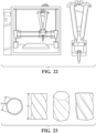
- the mixing blade 44 is further defined as a helical mixing blade, which is shown generally at 70 in Figures 3 and 6-10 .
- the body 46 of the helical mixing blade 70 comprises a curved elongated chevron-shaped sheet describing a helical shape.
- the helical mixing blade 70 is typically axially symmetric, with the pair of opposing lateral edges 56 defined by the body 46 being disposed adjacent to, optionally in sealed relation with, the interior surface 34 of the housing 22.
- the nose 48 of the helical mixing blade 70 comprises a pair of the leading edges 58, which are radially opposed and outwardly-facing, with each of the leading edges 58 obliquely extending outward from one of the lateral edges 56 of the body 46 to converge at the apex 60.
- the tail 50 of the helical mixing blade 70 comprises a pair of the trailing edges 64, which are radially opposed and inwardly-facing, with each of the trailing edges 64 obliquely extending inward from one of the lateral edges 56 of the body 46 to converge at the vertex 66.
- the helical mixing blade 70 is configured as a single-twist circular helix. i.e., comprises an angle of rotation of 180 degrees and a constant diameter and pitch.
- the lateral sides 52 of the helical mixing blade 70 taper inwards toward the outlet 40, such that the helical mixing blade 70 comprises a degree of conicity (e.g. comprises a lateral diameter proximal the nose 48 greater than a lateral diameter proximal the tail 50, etc.).
- the helical mixing blade 70 is configured as a partial-twist helix, i.e., comprises an overall degree of rotation of less than 180 degrees, such as of 90 degrees, 120 degrees, etc.
- the helical mixing blade 70 may comprise other dimensions that are variable (i.e., increasing and/or decreasing) along the length thereof, such as a variable pitch, a variable gradient of rotation angle, etc.
- the helical mixing blade 70 comprises a uniform twist rate (e.g. of 0.5, 1, 1.5, or 2, as measured by number of turns per length) along the length thereof.
- the helical mixing blade 70 may comprise 2, 3, 4 or more different twists rates along the length thereof.
- the helical mixing blade 70 comprises a length to diameter ratio of from 0.5 to 5, such as 0.75, 1, 1.5, or 2 (length:diameter).
- the helical mixing blade 70 comprises a central axis parallel to, optionally coaxial with, the central axis 24 of the housing 22. In other embodiments, the helical mixing blade 70 comprises a degree of skewness (i.e., a central axis inclined with respect to the central axis 24 of the housing 22.
- the helical mixing blade 70 may be configured as a right-hand/counter-clockwise winding helix (i.e., a right-hand helical mixing blade, shown at 72) or a left-hand/clockwise winding helix (i.e., a left-hand helical mixing blade, shown at 74).
- the static mixer 20 may comprise both right and left-handed winding helical mixing blades 72, 74.
- the mixing blade 44 is further defined as a corrugated mixing blade, which is shown generally at 76 in Figures 4 , 11, and 12 .
- the body 46 of the corrugated mixing blade 76 comprises a generally planar elongated chevron-shaped sheet defining at least one, alternatively a plurality of, corrugations 78.
- the nose 48 of the corrugated mixing blade 76 comprises a pair of the leading edges 58, which are radially opposed and outwardly-facing, with each of the leading edges 58 obliquely extending outward from one of the lateral edges 56 of the body 46 to converge at the apex 60.
- the tail 50 of the corrugated mixing blade 76 comprises a pair of the trailing edges 64, which are radially opposed and inwardly-facing, with each of the trailing edges 64 obliquely extending inward from one of the lateral edges 56 of the body 46 to converge at the vertex 66.
- the corrugated mixing blade 76 typically comprises the pair of opposing lateral edges 56 defined by the body 46 disposed adjacent to, optionally in sealed relation with, the interior surface 34 of the housing 22.
- the lateral sides 52 of the corrugated mixing blade 76 taper inwards toward the outlet 40, such that the width of the corrugated mixing blade 76 at the nose 48 is greater than the width at the tail 50.
- the corrugated mixing blade 76 comprises a substantially constant width along the length of the body 46 (e.g. between the lateral edges 56).
- the corrugations 78 comprise ridges 80 and/or valleys 82, and are otherwise not particularly limited.
- the ridge 80 on one face 54 of the corrugated mixing blade 76 corresponds directly to a particular valley 82 on the opposing face 54.
- the ridges 80 and/or valleys 82 may be peaked, rounded, etc., and thus comprise a cross-sectional shape that is substantially triangular, ovoidal, etc.
- the corrugations 78 may be V-shaped, W-shaped, U-shaped, etc.
- the corrugated mixing blade 76 comprises a series of substantially V-shaped corrugations 78 spaced along the body 46, the V-shaped corrugations comprising alternating ridges 80 and valleys 82.
- the corrugated mixing blade 76 comprises a series of substantially W-shaped corrugations 78.
- the corrugations 78 are independently selected, and thus may be uniform (i.e., with each of the ridges 80 and/or valleys 82 the same as each other ridge 80 and/or valley 82) or different from one or each other, e.g. with regard to the shape and/or dimension (e.g. height, width, etc.) of any of the ridges 80 and/or valleys 82).
- the number of individual corrugations 78 is not limited, and will be selected by those of skill in the art, e.g. in view of a desired orientation, width, etc. of each corrugation 78, the overall length, width, thickness, etc. of the corrugated mixing blade 76, etc.
- the corrugated mixing blade 76 comprises from 1 to 100, alternatively from 2 to 50, alternatively from 3 to 25, alternatively from 4 to 20, alternatively from 5 to 15 corrugations 78.
- each of the corrugations 78 typically extends along the entirely of the corrugated mixing blade 76, i.e., from one edge thereof to an opposing edge thereof. In this fashion, each valley 82 is adapted to guide/direct a local flow of fluid across the corrugated mixing blade 76.
- the corrugations 78 may be oriented in any direction, such as longitudinally to extend from the nose 48 to the tail 50 (e.g. parallel to the central axis of the corrugated mixing blade 76), transversely to extend from one to the other of the lateral sides 52 (e.g.
- the corrugations 78 are offset from the central axis of the corrugated mixing blade 76 at an angle of from 0 to 90 degrees, such as from 15 to 75, alternatively from 30 to 60, alternatively of from 40 to 50, alternatively of 45 degrees.
- the corrugations 78 may be spaced apart along the body 46 or, alternatively, may be positioned directly adjacent one another (e.g. to maximize the number of corrugations on the corrugated mixing blade 76).
- one of the corrugations 78 may be separated from another by a distance of from 0.01 to 10 times the width of the one corrugation 78, such as a multiple of from 0.1 to 5, alternatively from 0.25 to 3, alternatively from 0.5 to 2, of the width, alternatively a distance the same as the width, of the one corrugation 78.
- the mixing blade 44 is further defined as a prismatic mixing blade, which is shown generally at 84 in Figures 5 and 13-15 .
- the body 46 of the prismatic mixing blade 84 comprises a generally prismatic shape, such as a triangular prismatic shape.
- the nose 48 of the prismatic mixing blade 84 comprises the leading edge 58 obliquely extending toward the inlet 38 from one of the lateral edges 56 of the body 46 to the apex 60.
- the tail 50 of the prismatic mixing blade 84 comprises the trailing edges 64 obliquely extending toward the inlet 38 from one of the lateral edge 56 of the body 46 to converge at the vertex 66.
- the leading edge 58 of the prismatic mixing blade 84 is tapered, with the front taper surfaces 62 extending inwardly toward the inlet 38 perpendicular to the leading edge 58 from the faces 54 to converge at the front taper angle ⁇ 1 .
- the prismatic mixing blade 84 comprises an elongated base 86.
- the front taper surfaces 62 extend from the base 86, such that the faces 54 and the front taper surfaces 62 are the same.
- the prismatic mixing blade 84 is disposed within the mixing cavity 36 such that the body 46 is obliquely inclined to the central axis 24 of the housing 22.
- one of the lateral edges 56 of the prismatic mixing blade 84 is typically disposed adjacent to, optionally in sealed relation with, a portion of the interior surface 34 of the housing 22.
- the other of the lateral edges 56 may also be disposed adjacent to, optionally in sealed relation with, the interior surface 34 of the housing 22 (i.e., opposite the portion adjacent the opposing lateral edge 56).
- the prismatic mixing blade 84 comprises a constant height and the leading edge 58 and the trailing edge 64 are substantially parallel to each other (i.e., the attack angle ⁇ and the release angle ⁇ are the same).
- the attack angle ⁇ and/or the release angle ⁇ may also be referred to as the angle of inclination of the prismatic mixing blade 84.
- the angle of inclination of prismatic mixing blade 84 may alternatively be defined as the angle at which the central axis of the prismatic mixing blade 84 is offset from parallel to the central axis 24 of the housing 22.
- the prismatic mixing blade 84 typically comprises an angle of inclination of less than 90 degrees, such as from 15 to 75, alternatively from 30 to 60, alternatively of from 40 to 50, alternatively of 45 degrees.
- one of the lateral edges 56 is spaced apart from the interior surface 34 of the side wall 30. In such embodiments, this lateral edge 56 may be obliquely inclined with respect to the central axis 24.
- one of the lateral edges 56 is disposed in sealed relation with the side wall 30 of the housing 22, and the other of the lateral edges 56 extends inwardly from the base 86 to the apex 60, such that the other of the lateral edges 56 is the same is a second leading 58.
- one of the lateral edges 56 is disposed in sealed relation with the side wall 30 and the other of the lateral edges 56 extends outwardly from the base 86 to the apex 60, such that the other of the lateral edges 56 is the same is a second trailing edge 64.
- the mixing blade 44 is a component of the mixing element 42.
- the mixing element 42 consists essentially of, alternatively consists of, the mixing blade 44. In other embodiments, however, the mixing element 42 comprises more than one of the mixing blade 44 (i.e., a plurality of mixing blades 44).
- the mixing element 42 may comprise any number of mixing blades 44, which are independently selected and may be the same as or different from any other of the mixing blades 44 of the mixing element 42.
- the mixing element 42 comprises from 2 to 100 of the mixing blades 44, such as from 2 to 50, alternatively from 2 to 35, alternatively from 2 to 30, alternatively from 2 to 25, alternatively from 5 to 25, alternatively from 5 to 20, alternatively from 10 to 20 of the mixing blades 44.
- the mixing blades 44 of the mixing element 42 may be arranged in any order, e.g. based on the type(s) of mixing blade 44 utilized, the number of mixing blades 44 in the arrangement, etc.
- the mixing element 42 comprises a row of the mixing blades 44 disposed laterally across the mixing cavity 36, e.g. along a width or diameter thereof, tangentially to the diameter of the mixing cavity 36, etc.
- the row may comprise at least 2, alternatively at least 3, alternatively at least 5 of the mixing blades 44.
- Each mixing blade 44 in the row adjoins at least one other mixing blade 44. In this fashion, the mixing blades 44 may each be in contact with or spaced apart from adjacent mixing blades 44 in the row.
- each of the mixing blades 44 in the row may be disposed in the same or a different orientation with respect to one another, as described in further detail below.
- the mixing element 42 comprises more than one row, such as at least 2, alternatively at least 3, alternatively at least 5 rows of the mixing blades 44, which rows are each independently selected and may be the same as or different from any other of the rows (e.g. with regard to the number of mixing blades 44, the type(s) of mixing blades 44 utilized, the spacing between adjacent mixing blades 44, etc.).
- the mixing element 42 comprises a stack of the mixing blades 44 disposed longitudinally within the mixing cavity 36, e.g. along a length thereof, along and/or coaxial to the central axis 24, etc.
- the stack may comprise at least 2, alternatively at least 3, alternatively at least 5 of the mixing blades 44.
- Each mixing blade 44 in the stack adjoins at least one other mixing blade 44.
- the mixing blades 44 may each be in contact with or spaced apart from adjacent mixing blades 44 in the stack.
- each of the mixing blades 44 in the stack may be disposed in the same or a different orientation with respect to one another, as described in further detail below.
- the stack comprises at least 2 adjacent mixing blades 44 in axially offset, optionally axially orthogonal, relation to one another.
- the mixing element 42 comprises more than one stack, such as at least 2, alternatively at least 3, alternatively at least 5 stacks of the mixing blades 44, which are each independently selected and may be the same as or different from any other of the stacks (e.g. with regard to the number of mixing blades 44, the type(s) of mixing blade 44 utilized, the spacing between adjacent mixing blades 44, etc.).
- the type, number, and/or arrangement of the mixing blades 44 in the mixing element 42 are independently selected.
- the mixing element 42 comprises a row of the corrugated mixing blades 76 described above.
- each of the corrugated mixing blades 76 are disposed in parallel face-to-face spaced apart relation with respect to each other. The spacing is not particularly limited, but is generally selected such that adjacent corrugated mixing blades 76 present a gap between the outermost ends of the ridges 80 of the corrugations 78.
- adjoining corrugated mixing blades 76 in the row are selected with opposing corrugations, such that the direction of the corrugations 78 of one of the corrugated mixing blades 76 is not parallel to the direction of the corrugations 78 of any adjacent corrugated mixing blades 76 in the row.
- each of the corrugated mixing blades 76 comprise corrugations 78 offset from the central axis 24 by 45 degrees, with the corrugated mixing blades 76 oriented such that the corrugations 78 of adjacent corrugated mixing blades 76 in the row extend perpendicular to each other.
- the corrugated mixing blades 76 are oriented such that the corrugations 78 of adjacent corrugated mixing blades 76 in the row extend parallel to each other.
- the mixing element 42 comprises a row of the prismatic mixing blades 84 described above.
- each of the prismatic mixing blades 84 are disposed in transversely spaced crossing relation with respect to each other. More particularly, each of the prismatic mixing blades 84 is obliquely inclined to the central axis 24, with adjoining prismatic mixing blades 84 alternating between two opposing directions of inclination in the row, such that each of the prismatic mixing blades 84 is arranged in transversely crossing relation to each adjacent prismatic mixing blade(s) 84 in the row.
- the mixing element 42 comprises at least 2, alternatively at least 3, of the prismatic mixing blades 84 in the row, although more of the prismatic mixing blades 84 may be utilized.
- the mixing element 42 comprises more than one of the rows of the prismatic mixing blades 84, such as 2, 3, 4, 5, or more of such rows.
- each of the rows is typically spaced apart along the length of the mixing cavity 36.
- the mixing element 42 comprises a stack of the prismatic mixing blades 84.
- each of the prismatic mixing blades 84 in the stack is spaced apart and coaxial along the length of the mixing cavity 36 with adjacent prismatic mixing blades 84 in the stack.
- the mixing element 42 comprises a stack of rows of the prismatic mixing blades 84, as shown in Figure 14 .
- the mixing element 42 is a component of the static mixer 20.
- the static mixer comprises but one of the mixing element 42.
- the static mixer 20 comprises a plurality of the mixing elements 42 disposed in a series along the central axis 24 of the housing 22.
- the series of mixing elements 42 may comprise any number of individual mixing elements 42, which are independently selected and may be the same as or different from any other of the mixing elements 42 in the series (e.g. with respect to type(s) of mixing blades utilized, etc.).
- the static mixer 20 comprises a series of from 2 to 100 of the mixing elements 42, such as from 2 to 50, alternatively from 2 to 35, alternatively from 2 to 30, alternatively from 2 to 25, alternatively from 5 to 25, alternatively from 5 to 20, alternatively from 10 to 20 of the mixing elements 42.
- Each of the mixing elements 42 in the series adjoins (i.e., is adjacent to, alternatively in contact with) at least one other mixing element 42. More particularly, as will be understood in view of the Figures, the mixing blades 44 of each mixing elements 42 in the series is adjacent the mixing blades 44 of another of the mixing elements 42 in the series. In this fashion, the mixing blades 44 may each be in contact with or spaced apart from the mixing blades 44 of adjacent mixing elements 42 in the series.
- each of the mixing elements 42 in the series may be disposed in the same or a different orientation with respect to one another, as described in further detail below.
- the static mixer 20 comprises at least 2 adjacent mixing elements 42 in axially offset, optionally axially orthogonal, relation to one another.
- one of the mixing elements 42 may be rotationally offset from another by any amount, such as by 45, 90, or 180 degrees, or various other amounts therebetween.
- one of the mixing elements 42 may be rotationally offset from another of the mixing elements 42 in the series by an amount of from 5 to 90 degrees, such as from 15 to 75, alternatively from 30 to 60, alternatively of from 40 to 50 degrees.
- one of the mixing elements 42 may be rotationally offset from another of the mixing elements 42 in the series by an amount of from 95 to 180 degrees, such as from 100 to 170, alternatively from 110 to 160, alternatively of from 120 to 150 degrees.
- the static mixer 20 comprises a series of mixing elements 42 each comprising but one of the helical mixing blade 70.
- the mixing elements 42 are selected such that adjacent mixing elements 42 in the series alternate between comprising the right and left-handed winding helical mixing blades 72, 74.
- the mixing elements 42 are disposed in the series such that the helical mixing blades 70 of each adjoining/adjacent mixing element 42 are disposed nose-to-tail (i.e., nose 48 to tail 50) within the mixing cavity 36.
- the mixing elements 42 in the series are rotationally offset from each adjacent mixing elements 42, such as by 45, 60, 75, or 90 degrees. While not shown, the mixing elements 42 of the series need not be touching one another, but may instead be spaced apart along the length of the mixing cavity 36.
- the static mixer 20 comprises a series of mixing elements 42 each comprising a row of the corrugated mixing blades 76.
- the mixing elements 42 are disposed in the series such that the corrugated mixing blades 76 of each adjoining/adjacent mixing element 42 are disposed nose-to-tail (i.e., nose 48 to tail 50) within the mixing cavity 36.
- the mixing elements 42 in the series are rotationally offset from each adjacent mixing elements 42, such as by 45, 60, 75, or 90 degrees.
- the mixing elements 42 of the series need not be touching one another, but may instead be spaced apart along the length of the mixing cavity 36.
- the static mixer 20 comprises a series of mixing elements 42 each comprising a row of the prismatic mixing blades 84.
- the mixing elements 42 are disposed in the mixing cavity 36 such that the mixing elements 42 in the series are rotationally offset from each adjacent mixing element 42, such as by 45, 60, 75, or 90 degrees.
- the mixing elements 42 of the series need not be touching one another, but may instead be spaced apart along the length of the mixing cavity 36.
- the static mixer 20 may comprise one or more temperature control units. While not shown, such temperature control units may be provided as an integral component of the static mixer 20 and/or as an auxiliary component coupled/ attached to the static mixer 20 or another device operatively coupled thereto, such as any of those described in further detail below.
- Suitable temperature control units may comprise, alternatively may be, a heating element, a cooling element, and/or an insulating element, each of which may be active or passive.
- active heating and/or cooling can be achieved by way of fluid convection, electrical or thermoelectrical means, or by phase change of materials at a particular range of temperatures.
- Insulating elements typically comprise thermally insulating materials, such as polymer foams, nano-foams, sol-gel materials, stone wools, and the like, or combinations thereof, or vacuum chambers or other such structural features known to slow and/or control heat transport.
- the static mixer 20 comprises the temperature control unit configured as a jacket 88 disposed about the mixing cavity 36 of the housing 22.
- the jacket 88 defines a chamber 90 in fluid communication with the housing 22, and is adapted to act as a heat exchanger to the side wall 30, e.g. to control the temperature of mixing cavity 36.
- the chamber 90 is not particularly limited, and may be configured with any shape, size, and/or dimensions suitable for the use and applications described herein. As shown with particularity in Figure 16B , in certain embodiments, the chamber 90 is substantially tubular in shape, and configured as a tubular coil 96 disposed about (e.g. coiled around) the mixing cavity 36. In such embodiments, the coil 96 is typically coaxial with the mixing cavity 36, and thus generally shares the central axis 24. While but a single coil 96 is show, the chamber 90 may comprise multiple coils 96 of varying diameter, such that the chamber 90 may be configured as a dual-layer coil (not shown) comprising an inner coil (e.g.
- the chamber 90 is not limited to the tubular configuration described above, but may instead by implemented in any other configuration suitable for heat-exchanging with the mixing cavity 36.
- the chamber 90 is configured as a continuous and open space surrounding the mixing cavity 36.
- the jacket 88 typically comprises inlet port 92 and outlet port 94, which are independently adapted for flow of a heating and/or cooling agent (e.g. air, a coolant/refrigerant, a warm or hot fluid such as water, etc.) into and out of, respectively, the chamber 90 from outside of the jacket 88.
- a heating and/or cooling agent e.g. air, a coolant/refrigerant, a warm or hot fluid such as water, etc.
- the inlet port 92 is configured to facilitate introduction (i.e., ingress) of the heating and/or cooling agent into the chamber 90
- the outlet port 94 is configured to facilitate removal (i.e., egress) of the heating and/or cooling agent from the mixing chamber 90.
- the inlet port 92 and the outlet port 94 each independently define a channel for passage of the heating and/or cooling agent therethrough.
- the inlet port 92 and the outlet port 94 may be independently sized, shaped, and/or otherwise configured, and may be integral with, fixed to, and/or otherwise connected and/or fastened to the jacket 88.
- the diameter of the chamber 90, inlet port 92, and outlet port 94 may be independently selected, e.g. to control the rate at which material is introduced to and/or removed from the chamber 90 of the jacket 88, respectively.
- the inlet port 92 and/or the outlet port 94 are variable in size.
- the chamber 90 may be unidirectional or bidirectional, such that, in some embodiments, the outlet port 94 may be used as an inlet for the heating and/or cooling agent and the inlet port 92 may be used as an outlet for the heating and/or cooling agent.
- the jacket 88 is monolithic in construction with the housing 22.
- the side wall 30 of the housing 22 defines the chamber 90 and, optionally, the inlet and outlet ports 92, 94.
- the housing 22 may comprise any additional components and/or structure, such as connection means 98 for securing additional components to the first end 26 and/or the second end 28.
- connection means 98 for securing additional components to the first end 26 and/or the second end 28.
- the housing 22 comprises connection means 98 at both the second end 28 (e.g. illustrated as threads 100 at the outlet 42) and the first end 26 (e.g. illustrated as connection plate 102 defining bolt holes 104).
- Suitable connection means include fasteners (e.g. threaded fasteners such as bolts, screws, etc., push fasteners, clamp fasteners, etc.) connectors (e.g. quick connectors, threaded connectors/connections, etc.), couplings (e.g. male-female couplings, press-couplings, etc.) clamps, adhesives, and the like, as well as various combinations thereof.
- the various components, and elements of such components, of the static mixer 20 described above may be manufactured of the same or different material(s), such as any one or more of the materials described below.
- the housing 22 is monolithic in construction and substantially homogeneous in composition (e.g. such that the side wall 30, inlet 38, and outlet 40 are integrally formed and/or formed of a single piece of material).
- the jacket 88 and the housing 22 are monolithic in construction, as described above, and may independently comprise the same or different material as each other.
- each of the mixing blades 44 is monolithic in construction and substantially homogeneous in composition, and may independently comprise the same or different material as the housing 22 and/or the jacket 88.
- each row and/or stack of the mixing blades 44 is monolithic in construction and, optionally, substantially homogeneous in composition.
- each mixing element 42 is monolithic in construction and, optionally, substantially homogeneous in composition, and may comprise the same or different material as the housing 22 and/or the jacket 88.
- the static mixer 20 comprises the series of the mixing elements 42, with the series being monolithic in construction and, optionally, substantially homogeneous in composition.
- the mixing element 42, alternatively the series of mixing elements 42, and the housing 22 are monolithic in construction and, optionally, substantially homogeneous in composition.
- the housing 22, jacket 88, and the mixing element 42, alternatively the series of mixing elements 42 are monolithic in construction and, optionally, substantially homogeneous in composition.
- the housing 22, jacket 88, and mixing element(s) 42 may each independently comprise multiple components of varying compositions joined together (e.g. via permanent, semi-permanent, or non-permanent connections). Moreover, each component may itself comprise a combination of different materials, and thus may not comprise a homogeneous composition throughout.
- the mixing blades 44 need not be the same in material composition as the side wall 30, but nonetheless may be joined together and/or integrally formed therewith.
- Materials suitable for use in or as the static mixer 20, or one or more of the components thereof include metals (e.g. steels, aluminums, magnesium, zinc, nickel, titanium, alloys, etc.), resins (e.g. thermoset and/or thermoplastic resins, such as epoxy, silicone, acrylic, urethane, bismaleimide, phenolics, vinyl esters, cyanate esters, polyamide, polyimide, polypropylene, polyethylene, polyester, etc.) and other polymeric materials, ceramics, and combinations thereof.
- metals e.g. steels, aluminums, magnesium, zinc, nickel, titanium, alloys, etc.
- resins e.g. thermoset and/or thermoplastic resins, such as epoxy, silicone, acrylic, urethane, bismaleimide, phenolics, vinyl esters, cyanate esters, polyamide, polyimide, polypropylene, polyethylene, polyester, etc.
- thermoset and/or thermoplastic resins such as epoxy, silicone, acrylic, urethane, bis
- the static mixer 20 comprises a resin or other such polymeric material.
- the housing 22, the mixing element(s) 42, and the jacket 88 each comprise a resin, which may be the same as or different from the resin of the other component(s).
- suitable resins typically comprise the reaction product of a monomer and a curing agent, although resins formed of self-polymerizing monomers (i.e., those acting as both a monomer and a curing agent) may also be utilized. It is to be appreciated that such resins are conventionally named/identified according to a particular functional group present in the reaction product.
- polyurethane resin represents a polymeric compound comprising a reaction product of an isocyanate (i.e., a monomer) and a polyol (i.e., a chain extended curing agent).
- the reaction of the isocyanate and the polyol create urethane functional groups, which were not present in either of the unreacted monomer or curing agent.
- resins are named according to a particular functional group present in the monomer (i.e., a cure site).
- epoxy resin represents a polymeric compound comprising a cross-linked reaction product of a monomer having one or more epoxide groups (i.e., an epoxide) and a curing agent.
- the epoxy resin is no longer an epoxy, or no longer includes epoxide groups, but for any unreacted or residual epoxide groups (i.e., cure sites), which may remain after curing, as understood in the art.
- resins may be named according to a functional group present in both the monomer and the reaction product (i.e., an unreacted functional group).
- the resin is selected from thermoset resins and thermoplastic resins.
- suitable thermoset and/or thermoplastic resins typically include polyamides (PA), such as Nylons; polyesters such as polyethylene terephthalates (PET), polybutylene terephthalates (PBT), polytrimethylene terephthalates (PTT), polyethylene naphthalates (PEN), liquid crystalline polyesters, and the like; polyolefins such as polyethylenes (PE), polypropylenes (PP), polybutylenes, and the like; styrenic resins; polyoxymethylenes (POM) such as acetal homopolymer; polycarbonates (PC); polymethylmethacrylates (PMMA); polyvinyl chlorides (PVC); polyphenylene sulfides (PPS); polyphenylene oxide (PPO), polyphenylene ethers (PPE); polyimides (PI); polyamideimides (PAI); polyetherimides (PEI); polysulfones (P
- melamine-type phenoxy resins
- fluorinated resins such as polytetrafluoroethylenes
- thermoplastic elastomers such as polystyrene types, polyolefin types, polyurethane types, polyester types, polyamide types, polybutadiene types, polyisoprene types, fluoro types, and the like; and copolymers, modifications, and combinations thereof.
- Particular resins will be selected by those of skill in the art, e.g. based on material to be mixed, environment in which the static mixer 20 is to be used, the manufacturing method(s) and/or technique(s) selected to prepare the static mixer 20, etc.
- the static mixer 20 is prepared via additive manufacturing utilizing a material selected from epoxy resins, urethane resins, urethane thermoplastic elastomers, urethane acrylates, and/or UV curable polymers or precursors thereof.
- the static mixer 20, or one or more of the components thereof is formed via an additive manufacturing (AM) process.
- AM additive manufacturing
- Various particular processes are described below, including particular methods and materials that may be utilized, independently or collectively, in or as the AM process to form the static mixer 20, or one or more of the components thereof.
- AM processes such as 3D-printing
- 3D-printing are typically referred to or classified based on a particular class of 3D printer utilized in the 3D printing process.
- these specific types of 3D printing processes include direct extrusion additive manufacturing, liquid additive manufacturing, fused filament fabrication, fused deposition modeling, direct ink deposition, material jetting, polyjetting, syringe extrusion, laser sintering, laser melting, stereolithography, powder bedding (binder jetting), electron beam melting, laminated object manufacturing, laser powder forming, ink-jetting, and the like.
- Such processes may be used independently or in combination in the method of this disclosure.
- 3D printers include extrusion additive manufacturing printers, liquid additive manufacturing printers, fused filament fabrication printers, fused deposition modeling printers, direct ink deposition printers, selective laser sintering printers, selective laser melting printers, stereolithography printers, powder bed (binder jet) printers, material jet printers, direct metal laser sintering printers, electron beam melting printers, laminated object manufacturing deposition printers, directed energy deposition printers, laser powder forming printers, polyjet printers, ink-jetting printers, material jetting printers, and syringe extrusion printers.
- one or more components of the static mixer 20 may be monolithic in construction and substantially homogeneous in composition. In such embodiments, these one or more components may be formed as a unitary construction in a single AM process. However, each component of the static mixer 20 may be independently formed, using the same or different AM process, and subsequently assembled and/or fused/coupled/connected together to prepare the static mixer 20.
- each of the mixing blades 44 is formed via the AM process.
- each row and/or stack of the mixing blades 44, alternatively each mixing element 42, alternatively the series of mixing elements 42 as a whole is formed via the AM process, e.g.
- the housing 22 and the jacket 88 are formed via the AM process, e.g. as a single construction or as individual pieces that are subsequently assembled together.
- the entire static mixer 20, comprising the housing 22, mixing element 42 or series of mixing elements 42, and jacket 88 is formed via the AM process.
- the static mixer 20 is formed as individual pieces/components, which are subsequently assembled and/or fused/coupled/connected together to prepare the static mixer 20.
- the static mixer 20 is formed via the AM process as a single construction.
- post-formation processing steps e.g.
- AM methods are suitable for preparing the static mixer 20 and/or particular features thereof. For example, when a monolithic construction, intricate shape(s), and/or small size(s) are desired, stereolithography (SLA), digital light projection (DLP), and variations thereof, as well as methods utilizing two-photon polymerization methods, may be used.
- SLA stereolithography
- DLP digital light projection
- the static mixer 20 provides for reduced pressure drop during use, resulting in a smoother and/or more controllable flow of fluid through the mixing cavity 36 compared to conventional static mixers, as evidenced by the Examples herein, as described in further detail below.
- This reduced drop in pressure allows for increased functionality, such as when mixing two-part reactive compositions.
- uniformly mixing of two-part silicones is critical for silicone extrusion additive manufacturing (SEAM).
- SEAM silicone extrusion additive manufacturing
- conventional static mixers are frequently employed due to high mixing efficiency.
- such conventional static mixers comprise a pressure that occurs from the mixing process, which results in delayed output and over/under dispensing of silicone.
- the inventive static mixer comprises a significantly decreased over-extrusion rate and consistency, owing to a reduced pressure need due to the improved design of the mixing elements 42.
- the static mixer 20 may be used to mix a variety of different materials, which may be fluids, suspensions, emulsions, etc.
- Examples of particular uses of the static mixer 20 include mixing reactants upstream of (i.e., in line and in front of) a chemical reactor, temperature homogenization of fluids before and/or after a source of heating or cooling (e.g. the temperature control unit and/or a heating and/or cooling element thereof), homogenizing of fluids with additives, initiating a curing reaction of a multi-component curable system, etc.
- the static mixer 20 is used to mix, alternatively to homogenize, at least two different fluids.
- Fluids suitable for use in the mixing method are not specifically limited, and may be in liquid or gas form.
- a source of a fluid is typically in fluid communication with the inlet 38 during use.
- the inlet 38 is in fluid communication with one or more sources of liquid and/or gas reactants, heated or cooled liquid and/or gas, additives, etc.
- a method of homogenizing at least two different fluids (i.e., the "mixing method") using the static mixer 20 is also provided.
- the mixing method comprises flowing the fluids simultaneously though the mixing cavity 36 of the static mixer 20, thereby homogenizing the fluids.
- the mixing method further comprises cooling the mixing cavity 36 via the jacket 88 (e.g. by passing a coolant through the chamber 90).
- the additive manufacturing system 106 (i.e., the "AM system 106") generally comprises the static mixer 20 and a nozzle 108 operatively coupled to the housing 22 (e.g. via connection means 98) at the second end 28 such that the nozzle 108 is in fluid communication with the mixing cavity 36 via the outlet 40.
- the AM system 106 further comprises a platform 110 and/or a head 112, which each may independently be moveable in any direction with respect to the other and/or an article being prepared during use.
- the AM system 106 may be/include any apparatus comprising the static mixer 20 and a nozzle (e.g. the nozzle 108) from which a composition may be dispensed.
- the outlet 40 itself may be adapted for use as the nozzle 108.
- the AM system 106 may be a 3D printer, or any other such apparatus capable of dispensing a material for building 3D articles, which are generally referred to or encompassed by the scope of a 3D printer.
- an AM system may include an active mixing unit, in addition to or in the place of the static mixer, and include a temperature control unit, adjacent, around or arranged close to the active mixing unit.
- the active mixing unit may contain one or more moving components, e.g. mixing elements that are not stationary, in contrast to a static mixer with no moving parts.
- Figs. 24A and 24B illustrate active mixing units including temperature control units in an AM system.
- AM additive manufacturing
- 3D printing is defined as “a process of joining materials to make parts [i.e., “joined material forming a functional element that could constitute all or a section of an intended product”] from 3D model data, usually layer upon layer, as opposed to subtractive manufacturing methodologies.” Synonyms/historical terms associated with and encompassed by 3D printing include additive fabrication, additive processes, additive techniques, additive layer manufacturing, layer manufacturing, solid freeform fabrication, and freeform fabrication. AM may also be referred to as rapid prototyping (RP). As used herein, “3D printing” is generally interchangeable with “additive manufacturing” and vice versa.
- the AM system 106 may be further defined, or otherwise described as, a fused filament fabrication printer, a fused deposition modeling printer, a direct ink deposition printer, a selective laser sintering printer, a selective laser melting printer, a stereolithography printer, a powder bed (binder jet) printer, a material jet printer, a direct metal laser sintering printer, an electron beam melting printer, a laminated object manufacturing deposition printer, a directed energy deposition printer, a laser powder forming printer, a polyjet printer, an ink-jetting printer, a material jetting printer, and/or a syringe extrusion printer.
- AM/ 3D printing technology components, elements, or devices may be incorporated or used in conjunction with the AM system 106.
- components, elements, or devices include extruders, printing bases/platforms (e.g. stationary and/or motion controlled printing bases/platforms), various sensors/detectors (e.g. cameras, laser displacement sensors), computers and/or controllers, and the like, which may each be used independently or as part of the AM system 106 (e.g. with the components in electronic communication with one another).
- 3D printing is generally associated with a host of related technologies used to fabricate physical objects from computer generated data sources. Some of these specific processes are included herein with reference to specific 3D printers. Further, some of these processes, and others, are described in greater detail below. Accordingly, many components and technologies may be utilized in connection with the method of this disclosure, as will be better understood in view of the description below.
- a method of forming a three-dimensional (3D) article with the AM system 106 (i.e., the "AM method") (not shown) is also provided.
- the AM method includes I) forming a composition with the static mixer 20.
- the AM method further comprises II) printing the composition on a substrate with the AM system 106 to give a first layer on the substrate.
- steps I) and II) may be repeated with independently selected composition(s) for any additional layer(s).
- the AM method may comprise exposing the layer(s) to a solidification condition.
- Forming the composition with the static mixer 20 is not limited, and may be carried out as described above, using any materials suitable for forming a composition suitable for use in an AM process. Examples of specific materials are described further below.
- printing the composition on the substrate to give the first layer can mimic any one of the aforementioned 3D printing processes, or other 3D printing processes understood in the art.
- suitable 3D printing processes are also described in U.S. Pat. Nos. 5,204,055 and 5,387,380 .
- 3D printing is generally associated with a host of related technologies used to fabricate physical objects from computer generated data sources. Some of these specific processes are included above with reference to specific 3D printers. Further, some of these processes, and others, are described in greater detail below.
- AM/3D printing processes have a common starting point, which is a computer generated data source or program which may describe an object.
- the computer generated data source or program can be based on an actual or virtual object. For example, an actual object can be scanned using a 3D scanner and scan data can be used to make the computer generated data source or program. Alternatively, the computer generated data source or program may be designed from scratch.
- the computer generated data source or program is typically converted into a standard tessellation language (STL) file format; however, other file formats can also or additionally be used.
- STL standard tessellation language
- the file is generally read into 3D printing software, which takes the file and optionally user input to separate it into hundreds, thousands or even millions of "slices".
- the 3D printing software typically outputs machine instructions, which may be in the form of G-code, which is read by the 3D printer to build each slice.
- the machine instructions are transferred to the 3D printer (i.e., the AM system 106), which then builds the object, layer by layer, based on this slice information in the form of machine instructions. Thicknesses of these slices may vary.
- II) printing the composition on a substrate mimics a conventional material extrusion process.
- Material extrusion generally works by extruding material (in this case, the composition) through a nozzle (e.g. the nozzle 108) to print one cross-section of an object, which may be repeated for each subsequent layer.
- the nozzle 108 may be heated, cooled or otherwise manipulated during printing, which may aid in dispensing the particular composition.
- the AM method mimics a conventional material jetting process.
- Material jetting printers often resemble traditional paper printers, e.g. inkjet printers. In material jetting, a print head moves around a print area jetting the particular composition. Repeating this process builds up the object one layer at a time.
- the nozzle 108 and/or build platform 110 generally moves in the X-Y (horizontal) plane before moving in the Z-axis (vertical) plane once each layer is complete. In this way, the object which becomes the 3D article is built one layer at a time from the bottom upwards. This process can use material for two different purposes, building the object and supporting overhangs in order to avoid extruding material into thin air.
- Ambient conditions may be manipulated or controlled during printing.
- the substrate may be heated, cooled, mechanically vibrated, or otherwise manipulated before, during, and/or after the steps of printing to assist with solidification and/or curing.
- the nozzle may be heated or cooled before, during, and/or after printing the first composition.
- more than one nozzle may be utilized with each nozzle having independently selected properties or parameters.
- the AM method may be carried out in a heated or a moisturized environment such that solidification and/curing initiates after each step of printing.
- the composition(s), static mixer 20, nozzle 108, or other component(s) of the AM system 106 may be manipulated (e.g.
- multi-part compositions can be stored in different conditions (e.g. with respect to temperature, humidity/environment, etc.), and subsequently mixed together just prior to printing to accommodate and selectively utilize different cure rates, e.g. to form multi-part components.
- the resulting object(s) may be subjected to different post-processing regimes, such as further heating, solidification, infiltration, bakeout, and/or firing. This may be done, for example, to expedite cure of any binder, to reinforce the 3D article prepared, to eliminate any curing/cured binder (e.g. by decomposition), to consolidate the core material (e.g. by sintering/melting), and/or to form a composite material blending the properties of powder and binder.
- different post-processing regimes such as further heating, solidification, infiltration, bakeout, and/or firing. This may be done, for example, to expedite cure of any binder, to reinforce the 3D article prepared, to eliminate any curing/cured binder (e.g. by decomposition), to consolidate the core material (e.g. by sintering/melting), and/or to form a composite material blending the properties of powder and binder.
- steps I) and II) may be repeated with independently selected composition(s) for additional layer(s) as desired.
- the method further comprises III) forming a second composition with the static mixer 20, and IV) printing the second composition on the first layer with the AM system 106 to give a second layer on the first layer.
- the second layer may only contact a portion of an exposed surface of the first layer.
- the second layer may build on the first layer selectively (i.e., on but a portion thereof).
- the second composition may be the same as or different from the first composition utilized to form the first layer.
- any description above relative to forming and/or printing the first composition to form the first layer is also applicable to forming and/or printing the second composition on the first layer to form the second layer, and each aspect of each step is independently selected.
- the AM method may optionally comprise repeating steps I) and II) (and/or steps III) and/or IV)) with independently selected composition(s) for any additional layer(s).
- the first layer, second layer (or subsequent or latter layer), and any additional layer(s), optionally included as described below, are referred to collectively herein as "the layers.”
- the layers as used herein in plural form, may relate to the layers at any stage of the AM method, e.g.
- any description below relative to a particular layer is also applicable to any other layer, as the layers are independently formed and selected.
- the layers can each be of various dimension, including thickness and width. Thickness and/or width tolerances of the layers may depend on the apparatus, nozzle, and/or printing process used, with certain printing processes having relatively high resolutions and others having relatively low resolutions. Thicknesses of the layers can be uniform or may vary, and average thicknesses of the layers can be the same or different. Depending on a configuration of the first layer, and any additional layers, the thickness may refer to an average thickness and may be uniform or non-uniform. Average thickness is generally associated with thickness of the layer immediately after printing.
- the layers independently have an average thickness of from about 1 to about 1,000,000, about 1 to about 10,000, about 2 to about 1,000, about 5 to about 750, about 10 to about 500, about 25 to about 250, or about 50 to 100 ⁇ m. Thinner and thicker thicknesses are also contemplated. This disclosure is not limited to any particular dimensions of any of the layers.
- the 3D article may comprise a single layer while having a thickness of 2 meters.
- the AM method comprises exposing the layer(s) to a solidification condition.
- the solidification condition may be any condition which contributes to solidification of the layers.
- solidification may be a result of curing or increasing a crosslink density of the layers.
- solidification may be the result of a physical change within a layer, e.g. drying or removing any vehicle which may be present in any of the composition(s) and/or corresponding layer(s), as described below with respect to suitable compositions. Because each layer is independently selected, the solidification condition may vary for each layer.
- the solidification condition may be selected from: (i) exposure to moisture; (ii) exposure to heat; (iii) exposure to irradiation; (iv) reduced ambient temperature; (v) exposure to solvent; (vi) exposure to mechanical vibration; or (vii) any combination of (i) to (vi).
- the solidification condition typically at least partially solidifies, alternatively solidifies, the layers.
- the layers may be exposed to the solidification condition at any time in the AM method, and exposure to the solidification condition need not be delayed until two or more layers are formed in the AM method.
- the layers may be exposed to the solidification condition individually and/or collectively.
- the first layer may be exposed to the solidification condition to at least partially solidify the first layer prior to forming the second layer thereon.
- exposing the first layer to the solidification condition forms an at least partially solidified first layer such that the second composition is printed on the at least partially solidified first layer.
- the second layer may be at least partially solidified prior to repeating any printing steps for additional layers.
- the layers may also be subjected or exposed to a solidification condition when in contact with one another, even if these layers were at least partially solidified iteratively prior to each printing step.
- At least partial solidification of the layer is generally indicative of cure; however, cure may be indicated in other ways, and solidification may be unrelated to curing.
- curing may be indicated by a viscosity increase, e.g. bodying of the layer, an increased temperature of the layer, a transparency/opacity change of the layer, an increased surface or bulk hardness, etc.
- physical and/or chemical properties of the layer are modified as each layer at least partially solidifies to provide the at least partially solidified layers, respectively.
- the term "at least partially solidified” means that the particular at least partially solidified layer substantially retains its shape upon exposure to ambient conditions.
- Ambient conditions refer to at least temperature, pressure, relative humidity, and any other condition that may impact a shape or dimension of the at least partially solidified layer.
- ambient temperature is room temperature.
- Ambient conditions are distinguished from solidification conditions, where heat (or elevated temperature) is applied.
- substantially retains its shape it is meant that a majority of the at least partially solidified layer retains its shape, e.g. the at least partially solidified layer does not flow or deform upon exposure to ambient conditions.
- Substantially may mean that at least about 50%, 60%, 70%, 80%, 90%, 95%, 96%, 97%, 98%, 99%, 99.5%, 99.9%, 99.99%, or at least about 99.999% or more of the volume of the at least partially solidified layer is maintained in the same shape and dimension over a period of time, e.g. after 1 minute, 5 minutes, 10 minutes, 30 minutes, 1 hour, 4 hours, 8 hours, 12 hours, 1 day, 1 week, 1 month, etc.
- substantially retaining shape means that gravity does not substantially impact shape of the at least partially solidified layer upon exposure to ambient conditions.
- the shape of the at least partially solidified layer may also impact whether the at least partially solidified layer substantially retains its shape. For example, when the at least partially solidified layer is rectangular or has another simplistic shape, the at least partially solidified layer may be more resistant to deformation at even lesser levels of solidification than at least partially solidified layers having more complex shapes. More specifically, prior to exposing one or more layers to the solidification condition, the first composition (as well as the second composition and any subsequent compositions) is generally flowable and may be in the form of a liquid, slurry, or gel, alternatively a liquid or slurry, alternatively a liquid. Viscosity of each composition can be independently adjusted depending on the type of apparatus and nozzle or other considerations.
- Adjusting viscosity can be achieved, for example, by heating or cooling any of the compositions, adjusting molecular weight of one or more components thereof, by adding or removing a solvent, carrier, and/or diluent, by adding a filler or thixotroping agent, etc.
- printing of the second composition to form the second layer occurs before the at least partially solidified first layer has reached a final solidified state, i.e., while the at least partially solidified first layer is still "green.”
- green encompasses a partial solidified and/or a partial cure but not a final solidified and/or cure state.
- the distinction between partial solidification and/or cure state and a final solidification and/or cure state is whether the partially solidified and/or cured layer can undergo further solidification, curing and/or crosslinking.
- Functional groups of the components of the first composition may be present even in the final solidified and/or cure state, but may remain unreacted due to steric hindrance or other factors.
- printing of the layers may be considered "wet-on-wet" such that the adjacent layers or filaments at least physically bond, and may also chemically bond, to one another.
- components in each of the layers or filaments may chemically cross-link/cure across the print line.
- the print line is referred to as any contact point between adjacent filaments, or adjacent layers.
- the layers may also be formed around one or more substructures that can provide support or another function of the 3D article.
- the compositions are not curable such that the layers are merely physically bonded to one another in the 3D article.
- any iterative steps of exposing the layers to a curing and/or solidification condition may effect cure of more than just the previously printed layer.
- the cure may extend beyond or across the print line, and because a composite including the layers is typically subjected to the solidification condition, any other partially cured and/or solidified layers may also further, alternatively fully, cure and/or solidify upon a subsequent step of exposing the layers to a curing and/or solidification condition.
- the AM method may comprise printing the second composition to form the second layer on the at least partially solidified first layer.
- the second layer Prior to printing another composition to form another layer on the second layer, the second layer may be exposed to a solidification condition such that printing another composition to form another layer on the second layer comprises printing another composition to form another layer on an at least partially solidified second layer.
- exposing the second layer to the solidification condition may, depending on the selection of the first and second compositions, also further cure and/or solidify the at least partially solidified first layer. The same is true for any additional or subsequent layers.
- inserts which may have varying shape, dimension, and may comprise any suitable material, may be disposed or placed on or at least partially in any layer during the AM method.
- an insert may be utilized in between subsequent printing steps, and the insert may become integral with the 3D article upon its formation.
- the insert may be removed at any step during the AM method, e.g. to leave a cavity or for other functional or aesthetic purposes. The use of such inserts may provide better aesthetics and economics over relying on printing alone.
- a composite including all or some of the layers may be subjected to a final solidification step, which may be a final cure step.
- a composite formed by printing and at least partially solidifying the layers may be subjected to a further step of solidification or further steps of solidification where layers may solidify under different types of solidification conditions.
- the final solidification step if desired, may be the same as or different from any prior solidification steps, e.g. iterative solidification steps associated with each or any layer.
- the total number of layers required will depend, for example, on the size and shape of the 3D article, as well as dimensions of the individual and collective layers.
- One of ordinary skill can readily determine how many layers are required or desired using conventional techniques, such as 3D scanning, rendering, modeling (e.g. parametric and/or vector based modeling), sculpting, designing, slicing, manufacturing and/or printing software.
- 3D scanning rendering, modeling (e.g. parametric and/or vector based modeling), sculpting, designing, slicing, manufacturing and/or printing software.
- modeling e.g. parametric and/or vector based modeling
- sculpting designing, slicing, manufacturing and/or printing software.
- the individual layers may not be identifiable.
- compositions utilized in the AM method are independently selected and may be the same as or different from one another.
- the composition or “the compositions” is applicable to the first and/or second compositions, and any subsequent or additional compositions utilized to print subsequent or additional layers, and are not to be construed as requiring the compositions to be the same as one another.
- At least one of the compositions comprises: (a) a silicone composition, (b) a polymer, (c) a metal, (d) a slurry, or (e) combinations thereof.
- At least one of the compositions comprises the silicone composition.
- Suitable silicone compositions may be independently selected from (a) hydrosilylation-curable silicone compositions; (b) condensation-curable silicone compositions; (c) thiol-ene reaction-curable silicone compositions; (d) free-radical-curable silicone compositions; and (e) ring-opening reaction curable silicone compositions.
- the silicone compositions are generally curable such that exposure to the solidification condition may be referred to as exposure to a curing condition.
- these silicone compositions may be cured via different curing conditions, such as exposure to moisture, exposure to heat, exposure to irradiation, etc.
- these silicone compositions may be curable upon exposure to different types of curing conditions, e.g. both heat and irradiation, which may be utilized together or as only one.
- exposure to a curing condition may cure or initiate cure of different types of silicone compositions.
- heat may be utilized to cure or initiate cure of condensation-curable silicone compositions, hydrosilylation-curable silicone compositions, and free radical-curable silicone compositions.
- the silicone compositions may have the same cure mechanism upon application of the curing condition, but may still be independently selected from one another.
- the first composition may comprise a condensation-curable silicone composition
- the second composition may also comprise a condensation-curable silicone composition, wherein the condensation-curable silicone compositions differ from one another, e.g. by components, relative amounts thereof, etc.
- each of the silicone compositions utilized in the method cures via the same cure mechanism upon application of the curing condition. These embodiments easily allow for cure across the print line, if desired, as the components of in each of the silicone compositions may readily react with one another in view of having the same cure mechanism upon application of the curing condition.
- each of the silicone compositions may still differ from one another in terms of the actual components utilized and relative amounts thereof, even though the cure mechanism is the same in each of the silicone compositions.
- the cure mechanism is the same in each of the silicone compositions.
- there may be some cure across the print line when each of the layers cures via a different mechanism (e.g. hydrosilylation versus condensation) components in these layers may not be able to react with one another upon application of the curing condition, which may be desirable in other applications.
- the silicone compositions comprises a hydrosilylation-curable silicone composition.
- the hydrosilylation-curable silicone composition typically comprises: (A) an organopolysiloxane having an average of at least two silicon-bonded alkenyl groups or silicon-bonded hydrogen atoms per molecule; (B) an organosilicon compound having an average of at least two silicon-bonded hydrogen atoms or silicon-bonded alkenyl groups per molecule capable of reacting with the silicon-bonded alkenyl groups or silicon-bonded hydrogen atoms in the organopolysiloxane (A); and (C) a hydrosilylation catalyst.
- the organosilicon compound (B) includes at least two silicon-bonded hydrogen atoms per molecule, and when the organopolysiloxane (A) includes silicon-bonded hydrogen atoms, the organosilicon compound (B) includes at least two silicon-bonded alkenyl groups per molecule.
- the organosilicon compound (B) may be referred to as a cross-linker or cross-linking agent.
- the organopolysiloxane (A) and the organosilicon compound (B) may independently be linear, branched, cyclic, or resinous.
- the organopolysiloxane (A) and the organosilicon compound (B) may comprise any combination of M, D, T, and Q units.
- M, D, T, and Q represent the functionality of structural units of organopolysiloxanes.
- M represents the monofunctional unit R 0 3 SiO 1/2 .
- D represents the difunctional unit R 0 2 SiO 2/2 .
- T represents the trifunctional unit R 0 SiO 3/2 .
- Q represents the tetrafunctional unit SiO 4/2 .
- Generic structural formulas of these units are shown below: In these structures/formulae, each R 0 may be any hydrocarbon, aromatic, aliphatic, alkyl, alkenyl, or alkynl group.
- organopolysiloxane (A) and organosilicon compound (B) may be selected based on desired properties of the 3D article and layers during the AM method. For example, it may be desirable for the layers to be in the form of an elastomer, a gel, a resin, etc., and selecting the components of the silicone composition allows one of skill in the art to achieve a range of desirable properties.
- one of the organopolysiloxane (A) and the organosilicon compound (B) comprises a silicone resin, which typically comprises T and/or Q units in combination with M and/or D units.
- the silicone resin may be a DT resin, an MT resin, an MDT resin, a DTQ resin, an MTQ resin, an MDTQ resin, a DQ resin, an MQ resin, a DTQ resin, an MTQ resin, or an MDQ resin.
- the layer(s) and resulting 3D article have increased rigidity.
- the organopolysiloxane (A) and/or the organosilicon compound (B) is an organopolysiloxane comprising repeating D units.
- Such organopolysiloxanes are substantially linear but may include some branching attributable to T and/or Q units. Alternatively, such organopolysiloxanes are linear.
- the layer(s) and resulting 3D article are elastomeric.
- the silicon-bonded alkenyl groups and silicon-bonded hydrogen atoms of the organopolysiloxane (A) and the organosilicon compound (B), respectively, may independently be pendent, terminal, or in both positions.
- subscripts y and z are generally 0, whereas for resins, subscripts y and/or z >0.
- the subscript w may have a value of from 0 to 0.9999, alternatively from 0 to 0.999, alternatively from 0 to 0.99, alternatively from 0 to 0.9, alternatively from 0.9 to 0.999, alternatively from 0.9 to 0.999, alternatively from 0.8 to 0.99, alternatively from 0.6 to 0.99.
- the subscript x typically has a value of from 0 to 0.9, alternatively from 0 to 0.45, alternatively from 0 to 0.25.
- the subscript y typically has a value of from 0 to 0.99, alternatively from 0.25 to 0.8, alternatively from 0.5 to 0.8.
- the subscript z typically has a value of from 0 to 0.99, alternatively from 0 to 0.85, alternatively from 0.85 to 0.95, alternatively from 0.6 to 0.85, alternatively from 0.4 to 0.65, alternatively from 0.2 to 0.5, alternatively from 0.1 to 0.45, alternatively from 0 to 0.25, alternatively from 0 to 0.15.
- each R 1 is a C 1 to C 10 hydrocarbyl group, which may be substituted or unsubstituted, and which may include heteroatoms within the hydrocarbyl group, such as oxygen, nitrogen, sulfur, etc.
- Acyclic hydrocarbyl and halogen-substituted hydrocarbyl groups containing at least 3 carbon atoms can have a branched or unbranched structure.
- hydrocarbyl groups represented by R 1 include, but are not limited to, alkyl groups, such as methyl, ethyl, propyl, 1-methylethyl, butyl, 1-methylpropyl, 2-methylpropyl, 1,1-dimethylethyl, pentyl, 1-methylbutyl, 1-ethylpropyl, 2-methylbutyl, 3-methylbutyl, 1,2-dimethylpropyl, 2,2-dimethylpropyl, hexyl, heptyl, octyl, nonyl, and decyl; cycloalkyl groups, such as cyclopentyl, cyclohexyl, and methylcyclohexyl; aryl groups, such as phenyl and naphthyl; alkaryl groups, such as tolyl and xylyl; and aralkyl groups, such as benzyl and phenethyl.
- alkyl groups such as methyl,
- halogen-substituted hydrocarbyl groups represented by R 1 include, but are not limited to, 3,3,3-trifluoropropyl, 3-chloropropyl, chlorophenyl, dichlorophenyl, 2,2,2-trifluoroethyl, 2,2,3,3-tetrafluoropropyl, and 2,2,3,3,4,4,5,5-octafluoropentyl.
- the alkenyl groups represented by R 2 typically have from 2 to 10 carbon atoms, alternatively from 2 to 6 carbon atoms, and are exemplified by, for example, vinyl, allyl, butenyl, hexenyl, and octenyl.
- the organosilicon compound (B) may be further defined as an organohydrogensilane, an organopolysiloxane an organohydrogensiloxane, or a combination thereof.
- the structure of the organosilicon compound (B) can be linear, branched, cyclic, or resinous.
- the silicon-bonded hydrogen atoms can be located at terminal, pendant, or at both terminal and pendant positions.
- Cyclosilanes and cyclosiloxanes typically have from 3 to 12 silicon atoms, alternatively from 3 to 10 silicon atoms, alternatively from 3 to 4 silicon atoms.
- the organohydrogensilane can be a monosilane, disilane, trisilane, or polysilane.
- Hydrosilylation catalyst (C) includes at least one hydrosilylation catalyst that promotes the reaction between the organopolysiloxane (A) and the organosilicon compound (B).
- the hydrosilylation catalyst (C) can be any of the well-known hydrosilylation catalysts comprising a platinum group metal (i.e., platinum, rhodium, ruthenium, palladium, osmium and iridium) or a compound containing a platinum group metal.
- the platinum group metal is platinum, based on its high activity in hydrosilylation reactions.
- hydrosilylation catalysts suitable for (C) include the complexes of chloroplatinic acid and certain vinyl-containing organosiloxanes disclosed by Willing in U.S. Pat. No. 3,419,593 .
- a catalyst of this type is the reaction product of chloroplatinic acid and 1,3-diethenyl-1,1,3,3-tetramethyldisiloxane.
- the hydrosilylation catalyst (C) can also be a supported hydrosilylation catalyst comprising a solid support having a platinum group metal on the surface thereof.
- a supported catalyst can be conveniently separated from organopolysiloxanes, for example, by filtering the reaction mixture.
- supported catalysts include, but are not limited to, platinum on carbon, palladium on carbon, ruthenium on carbon, rhodium on carbon, platinum on silica, palladium on silica, platinum on alumina, palladium on alumina, and ruthenium on alumina.
- the hydrosilylation catalyst (C) can also be a microencapsulated platinum group metal-containing catalyst comprising a platinum group metal encapsulated in a thermoplastic resin.
- Hydrosilylation-curable silicone compositions including microencapsulated hydrosilylation catalysts are stable for extended periods of time, typically several months or longer, under ambient conditions, yet cure relatively rapidly at temperatures above the melting or softening point of the thermoplastic resin(s).
- Microencapsulated hydrosilylation catalysts and methods of preparing them are well known in the art, as exemplified in U.S. Pat. No. 4,766,176 and the references cited therein, and U.S. Pat. No. 5,017,654 .
- the hydrosilylation catalyst (C) can be a single catalyst or a mixture comprising two or more different catalysts that differ in at least one property, such as structure, form, platinum group metal, complexing ligand, and thermoplastic resin.
- the hydrosilylation catalyst (C) may also, or alternatively, be a photoactivatable hydrosilylation catalyst, which may initiate curing via irradiation and/or heat.
- the photoactivatable hydrosilylation catalyst can be any hydrosilylation catalyst capable of catalyzing the hydrosilylation reaction, particularly upon exposure to radiation having a wavelength of from 150 to 800 nanometers (nm).
- photoactivatable hydrosilylation catalysts include, but are not limited to, platinum(II) ⁇ -diketonate complexes such as platinum(II) bis(2,4-pentanedioate), platinum(II) bis(2,4-hexanedioate), platinum(II) bis(2,4-heptanedioate), platinum(II) bis(1-phenyl-1,3-butanedioate, platinum(II) bis(1,3-diphenyl-1,3-propanedioate), platinum(II) bis(1,1,1,5,5,5-hexafluoro-2,4-pentanedioate); ( ⁇ -cyclopentadienyl)trialkylplatinum complexes, such as (Cp)trimethylplatinum, (Cp)ethyldimethylplatinum, (Cp)triethylplatinum, (chloro-Cp)trimethylplatinum
- the photoactivatable hydrosilylation catalyst is a Pt(II) ⁇ -diketonate complex and more typically the catalyst is platinum(II) bis(2,4-pentanedioate).
- the hydrosilylation catalyst (C) can be a single photoactivatable hydrosilylation catalyst or a mixture comprising two or more different photoactivatable hydrosilylation catalysts.
- the concentration of the hydrosilylation catalyst (C) is sufficient to catalyze the addition reaction between the organopolysiloxane (A) and the organosilicon compound (B). In certain embodiments, the concentration of the hydrosilylation catalyst (C) is sufficient to provide typically from 0.1 to 1000 ppm of platinum group metal, alternatively from 0.5 to 100 ppm of platinum group metal, alternatively from 1 to 25 ppm of platinum group metal, based on the combined weight of the organopolysiloxane (A) and the organosilicon compound (B).
- the hydrosilylation-curable silicone composition may be a two-part composition where the organopolysiloxane (A) and organosilicon compound (B) are in separate parts.
- the hydrosilylation catalyst (C) may be present along with either or both of the organopolysiloxane (A) and organosilicon compound (B).
- the hydrosilylation catalyst (C) may be separate from the organopolysiloxane (A) and organosilicon compound (B) in a third part such that the hydrosilylation reaction-curable silicone composition is a three-part composition.
- the hydrosilylation-curable silicone composition comprises ViMe 2 (Me 2 SiO) 128 SiMe 2 Vi as the organopolysiloxane (A), Me 3 SiO(Me 2 SiO) 14 (MeHSiO) 16 SiMe 3 as the organosilicon compound (B) and a complex of platinum with divinyltretramethyldisiloxane as (C) such that platinum is present in a concentration of 5 ppm based on (A), (B) and (C).
- hydrosilylation-curable silicone compositions may vary.
- hydrosilylation-curable silicone composition may be solidified or cured upon exposure to irradiation and/or heat.
- hydrosilylation catalyst C
- photoactivatable hydrosilylation catalysts are typically utilized when curing via irradiation is desired.
- the silicone compositions comprises a condensation-curable silicone composition.
- the condensation-curable silicone composition typically comprises (A') an organopolysiloxane having an average of at least two silicon-bonded hydroxyl or hydrolysable groups per molecule; optionally (B') an organosilicon compound having an average of at least two silicon-bonded hydrogen atoms, hydroxyl groups, or hydrolysable groups per molecule; and (C') a condensation catalyst.
- any parameter or condition may be selectively controlled during the AM method or any individual step thereof, relative humidity and/or moisture content of ambient conditions may be selectively controlled to further impact a cure rate of condensation-curable silicone compositions.
- the organopolysiloxane (A') and the organosilicon compound (B') may independently be linear, branched, cyclic, or resinous.
- the organopolysiloxane (A') and the organosilicon compound (B') may comprise any combination of M, D, T, and Q units, as with the organopolysiloxane (A') and the organosilicon compound (B') disclosed above.
- organopolysiloxane (A') and organosilicon compound (B') may be selected based on desired properties of the 3D article and layers during the AM method. For example, it may be desirable for the layers to be in the form of an elastomer, a gel, a resin, etc., and selecting the components of the silicone composition allows one of skill in the art to achieve a range of desirable properties.
- one of the organopolysiloxane (A') and the organosilicon compound (B') comprises a silicone resin, which typically comprises T and/or Q units in combination with M and/or D units.
- the silicone resin may be a DT resin, an MT resin, an MDT resin, a DTQ resin, an MTQ resin, an MDTQ resin, a DQ resin, an MQ resin, a DTQ resin, an MTQ resin, or an MDQ resin.
- the condensation-curable silicone composition comprises a resin
- the layer(s) and resulting 3D article have increased rigidity.
- the organopolysiloxane (A') and/or the organosilicon compound (B') is an organopolysiloxane comprising repeating D units.
- Such organopolysiloxanes are substantially linear but may include some branching attributable to T and/or Q units. Alternatively, such organopolysiloxanes are linear.
- the layer(s) and resulting 3D article are elastomeric.
- the silicon-bonded hydroxyl groups and silicon-bonded hydrogen atoms, hydroxyl groups, or hydrolysable groups of the organopolysiloxane (A') and the organosilicon compound (B'), respectively, may independently be pendent, terminal, or in both positions.
- silicon-bonded hydroxyl groups result from hydrolyzing silicon-bonded hydrolysable groups. These silicon-bonded hydroxyl groups may condense to form siloxane bonds with water as a byproduct.
- hydrolysable groups include the following silicon-bonded groups: H, a halide group, an alkoxy group, an alkylamino group, a carboxy group, an alkyliminoxy group, an alkenyloxy group, or an N-alkylamido group.
- Alkylamino groups may be cyclic amino groups.
- subscripts y' and z' are generally 0, whereas for resins, subscripts y' and/or z' >0.
- the subscript w' may have a value of from 0 to 0.9999, alternatively from 0 to 0.999, alternatively from 0 to 0.99, alternatively from 0 to 0.9, alternatively from 0.9 to 0.999, alternatively from 0.9 to 0.999, alternatively from 0.8 to 0.99, alternatively from 0.6 to 0.99.
- the subscript x' typically has a value of from 0 to 0.9, alternatively from 0 to 0.45, alternatively from 0 to 0.25.
- the subscript y' typically has a value of from 0 to 0.99, alternatively from 0.25 to 0.8, alternatively from 0.5 to 0.8.
- the subscript z' typically has a value of from 0 to 0.99, alternatively from 0 to 0.85, alternatively from 0.85 to 0.95, alternatively from 0.6 to 0.85, alternatively from 0.4 to 0.65, alternatively from 0.2 to 0.5, alternatively from 0.1 to 0.45, alternatively from 0 to 0.25, alternatively from 0 to 0.15.
- the condensation-curable silicone composition further comprises the organosilicon compound (B').
- the organosilicon compound (B') may be linear, branched, cyclic, or resinous.
- the organosilicon compound (B') has the formula F d q SiX 4-q , wherein R 1 is defined above, X is a hydrolysable group, and q is 0 or 1.
- the organosilicon compound (B') can be a single silane or a mixture of two or more different silanes, each as described above. Also, methods of preparing tri- and tetra-functional silanes are well known in the art; many of these silanes are commercially available.
- the concentration of the organosilicon compound (B') in the condensation-curable silicone composition is sufficient to cure (cross-link) the organopolysiloxane (A').
- the particular amount of the organosilicon compound (B') utilized depends on the desired extent of cure, which generally increases as the ratio of the number of moles of silicon-bonded hydrolysable groups in the organosilicon compound (B') to the number of moles of silicon-bonded hydroxy groups in the organopolysiloxane (A') increases.
- the optimum amount of the organosilicon compound (B') can be readily determined by routine experimentation.
- the condensation catalyst (C') can be any condensation catalyst typically used to promote condensation of silicon-bonded hydroxy (silanol) groups to form Si-O-Si linkages.
- condensation catalysts include, but are not limited to, amines; and complexes of lead, tin, zinc, and iron with carboxylic acids.
- the condensation catalyst (C 1 ) can be selected from tin(II) and tin(IV) compounds such as tin dilaurate, tin dioctoate, and tetrabutyl tin; and titanium compounds such as titanium tetrabutoxide.
- the concentration of the condensation catalyst (C') is typically from 0.1 to 10% (w/w), alternatively from 0.5 to 5% (w/w), alternatively from 1 to 3% (w/w), based on the total weight of the organopolysiloxane (A') in the condensation-curable silicone composition.
- the condensation-curable silicone composition is typically a two-part composition where the organopolysiloxane (A') and condensation catalyst (C') are in separate parts.
- the organosilicon compound (B') is typically present along with the condensation catalyst (C').
- the condensation-curable silicone composition may be a three-part composition, where the organopolysiloxane (A'), the organosilicon compound (B') and condensation catalyst (C') are in separate parts.
- condensation-curable silicone compositions may vary.
- condensation-curable silicone composition may be solidified or cured upon exposure to ambient conditions, a moisturized atmosphere, and/or heat, although heat is commonly utilized to accelerate solidification and curing.
- the silicone compositions comprises a free radical-curable silicone composition.
- the free radical-curable silicone composition comprises (A") an organopolysiloxane having an average of at least two silicon-bonded unsaturated groups and (C") a free radical initiator.
- the organopolysiloxane (A") may be linear, branched, cyclic, or resinous.
- the organopolysiloxane (A") may comprise any combination of M, D, T, and Q units, as with the organopolysiloxane (A') and the organosilicon compound (B') disclosed above.
- the particular organopolysiloxane (A") may be selected based on desired properties of the 3D article and layers during the AM method. For example, it may be desirable for the layers to be in the form of an elastomer, a gel, a resin, etc., and selecting the components of the silicone composition allows one of skill in the art to achieve a range of desirable properties.
- the organopolysiloxane (A") comprises a silicone resin, which typically comprises T and/or Q units in combination with M and/or D units.
- the silicone resin may be a DT resin, an MT resin, an MDT resin, a DTQ resin, an MTQ resin, an MDTQ resin, a DQ resin, an MQ resin, a DTQ resin, an MTQ resin, or an MDQ resin.
- the hydrosilylation-curable silicone composition comprises a resin
- the layer(s) and resulting 3D article have increased rigidity.
- the organopolysiloxane (A") comprises repeating D units.
- Such organopolysiloxanes are substantially linear but may include some branching attributable to T and/or Q units.
- such organopolysiloxanes are linear.
- the layer(s) and resulting 3D article are elastomeric.
- the silicon-bonded unsaturated groups of the organopolysiloxane (A") may be pendent, terminal, or in both positions.
- the silicon-bonded unsaturated groups may include ethylenic unsaturation in the form of double bonds and/or triple bonds.
- Exemplary examples of silicon-bonded unsaturated groups include silicon-bonded alkenyl groups and silicon-bonded alkynyl groups.
- subscripts y" and z" are generally 0, whereas for resins, subscripts y" and/or z" >0.
- the subscript w" may have a value of from 0 to 0.9999, alternatively from 0 to 0.999, alternatively from 0 to 0.99, alternatively from 0 to 0.9, alternatively from 0.9 to 0.999, alternatively from 0.9 to 0.999, alternatively from 0.8 to 0.99, alternatively from 0.6 to 0.99.
- the subscript x" typically has a value of from 0 to 0.9, alternatively from 0 to 0.45, alternatively from 0 to 0.25.
- the subscript y" typically has a value of from 0 to 0.99, alternatively from 0.25 to 0.8, alternatively from 0.5 to 0.8.
- the subscript z" typically has a value of from 0 to 0.99, alternatively from 0 to 0.85, alternatively from 0.85 to 0.95, alternatively from 0.6 to 0.85, alternatively from 0.4 to 0.65, alternatively from 0.2 to 0.5, alternatively from 0.1 to 0.45, alternatively from 0 to 0.25, alternatively from 0 to 0.15.
- the unsaturated groups represented by R 4 may be the same or different and are independently selected from alkenyl and alkynyl groups.
- the alkenyl groups represented by R 4 which may be the same or different, are as defined and exemplified in the description of R 2 above.
- the alkynyl groups represented by R 4 which may be the same or different, typically have from 2 to about 10 carbon atoms, alternatively from 2 to 8 carbon atoms, and are exemplified by, but are not limited to, ethynyl, propynyl, butynyl, hexynyl, and octynyl.
- the free radical-curable silicone composition can further comprise an unsaturated compound selected from (i) at least one organosilicon compound having at least one silicon-bonded alkenyl group per molecule, (ii) at least one organic compound having at least one aliphatic carbon-carbon double bond per molecule, (iii) at least one organosilicon compound having at least one silicon-bonded acryloyl group per molecule; (iv) at least one organic compound having at least one acryloyl group per molecule; and (v) mixtures comprising (i), (ii), (iii) and (iv).
- the unsaturated compound can have a linear, branched, or cyclic structure.
- the organosilicon compound (i) can be an organosilane or an organosiloxane.
- the organosilane can be a monosilane, disilane, trisilane, or polysilane.
- the organosiloxane can be a disiloxane, trisiloxane, or polysiloxane.
- Cyclosilanes and cyclosiloxanes typically have from 3 to 12 silicon atoms, alternatively from 3 to 10 silicon atoms, alternatively from 3 to 4 silicon atoms.
- the silicon-bonded alkenyl group(s) can be located at terminal, pendant, or at both terminal and pendant positions.
- organosiloxanes include, but are not limited to, siloxanes having the following formulae: PhSi(OSiMe 2 Vi) 3 , Si(OSiMe 2 Vi) 4 , MeSi(OSiMe 2 Vi) 3 , and Ph 2 Si(OSiMe 2 Vi) 2 .
- the organic compound can be any organic compound containing at least one aliphatic carbon-carbon double bond per molecule, provided the compound does not prevent the organopolysiloxane (A") from curing to form a silicone resin film.
- the organic compound can be an alkene, a diene, a triene, or a polyene. Further, in acyclic organic compounds, the carbon-carbon double bond(s) can be located at terminal, pendant, or at both terminal and pendant positions.
- the organic compound can contain one or more functional groups other than the aliphatic carbon-carbon double bond.
- the suitability of a particular unsaturated organic compound for use in the free-radical curable silicone composition of the present invention can be readily determined by routine experimentation.
- organic compounds containing aliphatic carbon-carbon double bonds include, but are not limited to, 1,4-divinylbenzene, 1,3-hexadienylbenzene, and 1,2-diethenylcyclobutane.
- the unsaturated compound can be a single unsaturated compound or a mixture comprising two or more different unsaturated compounds, each as described above.
- the unsaturated compound can be a single organosilane, a mixture of two different organosilanes, a single organosiloxane, a mixture of two different organosiloxanes, a mixture of an organosilane and an organosiloxane, a single organic compound, a mixture of two different organic compounds, a mixture of an organosilane and an organic compound, or a mixture of an organosiloxane and an organic compound.
- the free radical initiator (C") is a compound that produces a free radical, and is utilized to initiate polymerization of the organopolysiloxane (A").
- the free radical initiator (C") produces a free radical via dissociation caused by irradiation, heat, and/or reduction by a reducing agent.
- the free radical initiator (C") may be an organic peroxide.
- organic peroxides include, diaroyl peroxides such as dibenzoyl peroxide, di-p-chlorobenzoyl peroxide, and bis-2,4-dichlorobenzoyl peroxide; dialkyl peroxides such as di-t-butyl peroxide and 2,5-dimethyl-2,5-di-(t-butylperoxy)hexane; diaralkyl peroxides such as dicumyl peroxide; alkyl aralkyl peroxides such as t-butyl cumyl peroxide and 1,4-bis(t-butylperoxyisopropyl)benzene; and alkyl aryl peroxides such as t-butyl perbenzoate, t-butyl peracetate, and t-butyl peroctoate.
- diaroyl peroxides such as dibenzoyl peroxide, di-p-chlorobenzoyl peroxid
- the organic peroxide (C") can be a single peroxide or a mixture comprising two or more different organic peroxides.
- the concentration of the organic peroxide is typically from 0.1 to 5% (w/w), alternatively from 0.2 to 2% (w/w), based on the weight of the organopolysiloxane (A").
- the free radical-curable silicone composition may be a two-part composition where the organopolysiloxane (A") and the free radical initiator (C") are in separate parts.
- the silicone compositions comprises a ring opening reaction-curable silicone composition.
- the ring opening reaction-curable silicone composition comprises (A′′′) an organopolysiloxane having an average of at least two epoxy-substituted groups per molecule and (C′′′) a curing agent.
- the ring opening reaction-curable silicone composition is not limited specifically to epoxy-functional organopolysiloxanes.
- Other examples of ring opening reaction-curable silicone compositions include those comprising silacyclobutane and/or benzocyclobutene.
- the organopolysiloxane (A′′′) may be linear, branched, cyclic, or resinous.
- the organopolysiloxane (A′′′) may comprise any combination of M, D, T, and Q units, as with the organopolysiloxane (A') and the organosilicon compound (B') disclosed above.
- the particular organopolysiloxane (A′′′) may be selected based on desired properties of the 3D article and layers during the AM method. For example, it may be desirable for the layers to be in the form of an elastomer, a gel, a resin, etc., and selecting the components of the silicone composition allows one of skill in the art to achieve a range of desirable properties.
- the organopolysiloxane (A′′′) comprises a silicone resin, which typically comprises T and/or Q units in combination with M and/or D units.
- the silicone resin may be a DT resin, an MT resin, an MDT resin, a DTQ resin, an MTQ resin, an MDTQ resin, a DQ resin, an MQ resin, a DTQ resin, an MTQ resin, or an MDQ resin.
- the hydrosilylation-curable silicone composition comprises a resin
- the layer(s) and resulting 3D article have increased rigidity.
- the organopolysiloxane (A′′′) comprises repeating D units.
- Such organopolysiloxanes are substantially linear but may include some branching attributable to T and/or Q units.
- such organopolysiloxanes are linear.
- the layer(s) and resulting 3D article are elastomeric.
- epoxy-substituted groups of the organopolysiloxane (A′′′) may be pendent, terminal, or in both positions.
- "Epoxy-substituted groups” are generally monovalent organic groups in which an oxygen atom, the epoxy substituent, is directly attached to two adjacent carbon atoms of a carbon chain or ring system.
- epoxy-substituted organic groups include, but are not limited to, 2,3-epoxypropyl, 3,4-epoxybutyl, 4,5-epoxypentyl, 2-glycidoxyethyl, 3-glycidoxypropyl, 4-glycidoxybutyl, 2-(3,4-epoxycylohexyl)ethyl, 3-(3,4-epoxycylohexyl)propyl, 2-(3,4-epoxy-3-methylcylohexyl)-2-methylethyl, 2-(2,3-epoxycylopentyl)ethyl, and 3-(2,3 epoxycylopentyl)propyl.
- subscripts y′′′ and z′′′ are generally 0, whereas for resins, subscripts y′′′ and/or z′′′ >0.
- Various alternative embodiments are described below with reference to w'", x'", y′′′ and z'".
- the subscript w′′′ may have a value of from 0 to 0.9999, alternatively from 0 to 0.999, alternatively from 0 to 0.99, alternatively from 0 to 0.9, alternatively from 0.9 to 0.999, alternatively from 0.9 to 0.999, alternatively from 0.8 to 0.99, alternatively from 0.6 to 0.99
- the subscript x′′′ typically has a value of from 0 to 0.9, alternatively from 0 to 0.45, alternatively from 0 to 0.25.
- the subscript y′′′ typically has a value of from 0 to 0.99, alternatively from 0.25 to 0.8, alternatively from 0.5 to 0.8.
- the subscript z′′′ typically has a value of from 0 to 0.99, alternatively from 0 to 0.85, alternatively from 0.85 to 0.95, alternatively from 0.6 to 0.85, alternatively from 0.4 to 0.65, alternatively from 0.2 to 0.5, alternatively from 0.1 to 0.45, alternatively from 0 to 0.25, alternatively from 0 to 0.15.
- the curing agent (C′′′) can be any curing agent suitable for curing the organopolysiloxane (A′′′).
- curing agents (C′′′) suitable for that purpose include phenolic compounds, carboxylic acid compounds, acid anhydrides, amine compounds, compounds containing alkoxy groups, compounds containing hydroxyl groups, or mixtures thereof or partial reaction products thereof. More specifically, examples of curing agents (C′′′) include tertiary amine compounds, such as imidazole; quaternary amine compounds; phosphorus compounds, such as phosphine; aluminum compounds, such as organic aluminum compounds; and zirconium compounds, such as organic zirconium compounds.
- a curing agent or curing catalyst or a combination of a curing agent and a curing catalyst can be used as the curing agent (C′′′).
- the curing agent (C′′′) can also be a photoacid or photoacid generating compound.
- the ratio of the curing agent (C′′′) to the organopolysiloxane (A′′′) is not limited. In certain embodiments, this ratio is from 0.1-500 parts by weight of the curing agent (C′′′) per 100 parts by weight of the organopolysiloxane (A′′′).
- the silicone compositions comprises a thiol-ene curable silicone composition.
- the thiol-ene curable silicone composition typically comprises: (A"") an organopolysiloxane having an average of at least two silicon-bonded alkenyl groups or silicon-bonded mercapto-alkyl groups per molecule; (B"") an organosilicon compound having an average of at least two silicon-bonded mercapto-alkyl groups or silicon-bonded alkenyl groups per molecule capable of reacting with the silicon-bonded alkenyl groups or silicon-bonded mercapto-alkyl groups in the organopolysiloxane (A""); (C"”) a catalyst; and (D"”) an optional organic compound containing two or more mercapto groups.
- the organopolysiloxane (A"") includes silicon-bonded alkenyl groups
- the organosilicon compound (B”") and/or the organic compound (D”") include at least two mercapto groups per molecule bonded to the silicon and/or in the organic compound
- the organosilicon compound (B”") includes at least two silicon-bonded alkenyl groups per molecule.
- the organosilicon compound (B”") and/or the organic compound (D"") may be referred to as a cross-linker or cross-linking agent.
- the catalyst (C"") can be any catalyst suitable for catalyzing a reaction between the organopolysiloxane (A"") and the organosilicon compound (B"") and/or the organic compound (D"").
- the catalyst (C"") is selected from: i) a free radical catalyst; ii) a nucleophilic reagent; and iii) a combination of i) and ii).
- Suitable free radical catalysts for use as the catalyst (C”") include photo-activated free radical catalysts, heat-activated free radical catalysts, room temperature free radical catalysts such as redox catalysts and alkylborane catalysts, and combinations thereof.
- Suitable nucleophilic reagents for use as the catalyst (C”") include amines, phosphines, and combinations thereof.
- the silicone compositions comprises a silicon hydride-silanol reaction curable silicone composition.
- the silicon hydride-silanol reaction curable silicone composition typically comprises: (A′′′ ⁇ ) an organopolysiloxane having an average of at least two silicon-bonded hydrogen atoms or at least two silicone bonded hydroxyl groups per molecule; (B′′′ ⁇ ) an organosilicon compound having an average of at least two silicon-bonded hydroxyl groups or at least two silicon bonded hydrogen atoms per molecule capable of reacting with the silicon-bonded hydrogen atoms or silicon-bonded hydroxyl groups in the organopolysiloxane (A′′′ ⁇ ); (C′′′ ⁇ ) a catalyst; and (D′′′ ⁇ ) an optional active hydrogen containing compound.
- the organosilicon compound (B′′′ ⁇ ) and/or the organic compound (D′′′ ⁇ ) include at least two hydroxyl groups per molecule bonded to the silicon and/or in the active hydrogen containing compound, and when the organopolysiloxane (A′′′ ⁇ ) includes silicon-bonded hydroxyl groups, the organosilicon compound (B′′′ ⁇ ) includes at least two silicon-bonded hydrogen atoms per molecule.
- the organosilicon compound (B′′′ ⁇ ) and/or the organic compound (D′′′ ⁇ ) may be referred to as a cross-linker or cross-linking agent.
- the catalyst (C′′′ ⁇ ) is selected from: i) a Group X metal-containing catalyst such as platinum; ii) a base such as metal hydroxide, amine, or phosphine; and iii) combinations thereof.
- Solidification conditions for such silicon hydride-silanol condensation-curable silicone compositions may vary. Typically, such compositions are mixed as a two-part system and subsequently cured under ambient conditions. However, heat may also be utilized during solidification.
- any of the silicone compositions may optionally and independently further comprise additional ingredients or components, especially if the ingredient or component does not prevent the organosiloxane of the composition from curing.
- additional ingredients include, but are not limited to, fillers; inhibitors; adhesion promoters; dyes; pigments; anti-oxidants; carrier vehicles; heat stabilizers; flame retardants; thixotroping agents; flow control additives; fillers, including extending and reinforcing fillers; and cross-linking agents.
- the composition further comprises ceramic powder. The amount of ceramic powder can vary and may depend on the 3D printing process being utilized.
- One or more of the additives can be present as any suitable wt.% of the particular silicone composition, such as about 0.1 wt.% to about 15 wt.%, about 0.5 wt.% to about 5 wt.%, or about 0.1 wt.% or less, about 1 wt.%, 2, 3, 4, 5, 6, 7, 8, 9, 10, 11, 12, 13, 14, or about 15wt.% or more of the silicone composition.
- the silicone compositions are shear thinning.
- Compositions with shear thinning properties may be referred to as psuedoplastics.
- compositions with shear thinning properties are characterized by having a viscosity which decreases upon an increased rate of shear strain. Said differently, viscosity and shear strain are inversely proportional for shear thinning compositions.
- the silicone compositions are shear thinning, the silicone compositions are particularly well suited for printing, especially when a nozzle or other dispense mechanism is utilized.
- a specific example of a shear-thing silicone composition is XIAMETERO 9200 LSR, commercially available from Dow Corning Corporation of Midland, MI.
- At least one of the compositions comprises the polymer.
- the polymer may be any of the silicone polymers described above.
- the polymer may comprise an organic polymer or resin.
- the polymer may comprise an organic-silicone hybrid polymer.
- the polymer may be disposed in a vehicle or solvent.
- the polymer may be a thermosetting and/or thermoplastic polymer or resin.
- suitable thermosetting and/or thermoplastic resins include epoxy, polyester, phenol, polyamide, polyimide, polyvinyl, polyvinyl ester (i.e., vinylester), and polyurethane resins, as well as modifications, and combinations thereof. Additionally, elastomers and/or rubbers can be added to or compounded with the uncured thermosetting and/or thermoplastic resin to improve certain properties such as impact strength.
- suitable thermosetting and/or thermoplastic resins include those described above.
- At least one of the compositions comprises the metal.
- the metal may be any of metal or alloy, and may be a liquid or slurry.
- a low-melting metal is used such that the at least one composition comprising the metal and/or the metal itself can be melted in an extruder and extrusion printed and/or deposited accordingly.
- sections comprising the metal may be formed during the printing process to add functionality (e.g. structural support, section separation, etc.). When the metal is a liquid, an appropriate solidification condition and/or mechanism is utilized.
- Such solidification conditions include sufficient cooling and forming a solid alloy with another material already presented on the substrate the liquid metal is being deposited onto.
- the metal is a slurry of metal particles in a carrier such as water or a non-oxidizing solvent.
- the printed section formed from slurry can be further processed, such as via laser melting, etching, and/or sintering.
- the slurry is a ceramic slurry.
- the ceramic slurry may be carried by water, and may be combined with one or more binders such as a polymer.
- the ceramic slurry can be dried/solidified via evaporation of the carrier (e.g. water) and/or drying.
- the dried/solidified ceramic slurry can be further processed or consolidated by heating, such as via convection, heat conduction, or radiation.
- Ceramics that may be used to form the ceramic slurry include oxides of various metals, carbides, nitrides, borides, silicides, and combinations and/or modifications thereof.
- the slurry is a metal slurry.
- the slurry comprises, alternatively is a polymer slurry.
- the polymer slurry is typically a solution or dispersion of a polymer in water or an organic solvent.
- the polymer slurry may comprise any suitable polymer, and typically comprises a viscosity for printing at ambient or elevated temperatures.
- compositions can be of various viscosities.
- the composition has a viscosity less than 0.5, less than 0.25, or less than 0.1 Pa.s (less than 500, less than 250, or less than 100, centistokes) at 25°C, alternatively a viscosity of from 0.001 to 1000 Pa.s (1 to 1,000,000 centistokes) at 25°C, alternatively from 0.001 to 100 Pa.s (1 to 100,000 centistokes) at 25°C, alternatively from 0.001 to 10 Pa.s (1 to 10,000 centistokes) at 25°C.
- Viscosity of each composition can be changed by altering the amounts and/or molecular weight of one or more components thereof.
- Viscosity may be adjusted to match components of the AM system 106 (e.g. the nozzle 108) to control heat, speed, or other parameters associated with printing.
- kinematic viscosity may be measured in accordance with ASTM D-445 (2011), entitled “Standard Test Method for Kinematic Viscosity of Transparent and Opaque Liquids (and Calculation of Dynamic Viscosity).”
- each composition utilized may independently be in a liquid, solid, or semi-solid form.
- each composition may be utilized as a liquid suitable for forming streams and/or droplets, a powder, and/or a heat-meltable solid, depending on the particular composition and printing conditions selected and as described above.
- any of the compositions described above may be a single part or a multi-part composition, as described above with reference to certain silicone compositions. Certain compositions are highly reactive such that multi-part compositions prevent premature mixing and curing of the components.
- the multi-part composition may be, for example, a two-part system, a three-part system, etc. contingent on the selection of the composition and the components thereof. Any component of the composition may be separate from and individually controlled with respect to the remaining components.
- the separate parts of the multi-part composition may are mixed in the static mixer 20 directly prior to printing (e.g. in line with the nozzle 108).
- a static mixer is having the design shown in Figures 6 and 18 , with is formed via stereolithography AM (SLA) printer (FormLabs ® Form 2, using FormLabs Standard Clear Resin (methacrylic acid ester mixture with photoinitiator)).
- SLA stereolithography AM
- FormLabs ® Form 2 using FormLabs Standard Clear Resin (methacrylic acid ester mixture with photoinitiator)
- the helical mixing elements were fabricated with a taper angle of ⁇ /6 radians, a release angle of ⁇ /4 radians, and a transfer angle of ⁇ /4 radians.
- a silicone composition (CaCO 3 filled, moisture curable silicone composition of viscosity 45 Pa.s (25 °C) and a shear rate of 100 s -1 ) is pushed through the static mixer of Example 1 and, separately, through a standard kenics-type mixer, in a simulated extrusion process at various extrusion rates, and the pressure to sustain such extrusion rates is monitored to assess the corresponding pressure drop, as set forth in Table 1 below. Table 1.
- Table 1 Over-Extrusion Assessment Results
- Example Extrusion Rate (mL/min) Plot 2 100 Figure 19A Comp. 1 100 Figure 19B 3 150 Figure 20A Comp. 2 150 Figure 20B 4 200 Figure 21A Comp. 3 200 Figure 21B
- Figures 19-21 show the pressures corresponding to the inventive static mixer and Figures 19-21B how the pressures corresponding to the comparative kenics-type mixer.
- the inventive static mixer includes a significantly lower pressure requirement (as measured by a pressure drop across the length of the mixer) to sustain a given extrusion rate compared to a standard kenics-type mixer.
- the inventive static mixer results in a significantly lower amount of over-extrusion compared to a standard kenics-type mixer, evidencing significant improvement for start-stop and tracking abilities for AM/3D-printing applications.
- An additive manufacturing system (two-part silicone SEAM machine, as shown in Figure 22 ) is prepared using the static mixer prepared above.
- the AM system is built on a thermoplastic material extrusion machine (Lulzbot, TAZ6) with twin progressive cavity pumps (ViscoTech) to finely dispense silicone.
- the AM system is utilized to prepare a 3D article, as shown in Figure 23 , with a slow curing silicone composition (Dow Silastic LTC 9400-50 LSR).
- a slow curing silicone composition (Dow Silastic LTC 9400-50 LSR).
- the twisted hexagon shape was selected due to the difficulty of preparing such an article using molds, due to the lack of flat surfaces and the complexity of machining a mold with the impression of the twisted surface.
Landscapes
- Chemical & Material Sciences (AREA)
- Engineering & Computer Science (AREA)
- Chemical Kinetics & Catalysis (AREA)
- Materials Engineering (AREA)
- Dispersion Chemistry (AREA)
- Manufacturing & Machinery (AREA)
- Mechanical Engineering (AREA)
- Physics & Mathematics (AREA)
- Optics & Photonics (AREA)
- Processing And Handling Of Plastics And Other Materials For Molding In General (AREA)
- Mixers Of The Rotary Stirring Type (AREA)
Claims (14)
- Statischer Mischer (20), umfassend:ein Gehäuse (22), das einen inneren Mischhohlraum (36) definiert, der sich in Längsrichtung entlang einer Mittelachse (24) zwischen einem Einlass (38) und einem Auslass (40) erstreckt und für eine axiale Strömung eines Fluids dahindurch angepasst ist; undein Mischelement (42), das innerhalb des Mischhohlraums (36) angeordnet ist, wobei das Mischelement (42) konfiguriert ist, um frei von einer Aufschlagoberläche zu sein, die im Wesentlichen senkrecht zu einer Hauptrichtung einer Fluidströmung durch den inneren Mischhohlraum (36) hindurch ausgerichtet ist und umfassend eine längliche Mischklinge (44), die in Längsrichtung innerhalb des Mischhohlraums (36) ausgerichtet ist und eine Nase (48) aufweist, die zu dem Einlass (38) hin axial ausgerichtet ist,dadurch gekennzeichnet, dass die Nase (48) der Mischklinge (44) ein Paar Vorderkanten (58) umfasst, die sich schräg nach innen und zu dem Einlass (38) hin von einer lateralen Seite der Mischklinge (44) erstrecken und an einem Scheitelpunkt (60) konvergent sind.
- Statischer Mischer nach Anspruch 1, wobei:(i) jede Vorderkante (58) zu einer radialen Ebene des Mischhohlraums (36) durch einen Angriffswinkel (γ) schräg ausgerichtet ist, wobei 0<γ<[π/2] Radianten;(ii) jede Vorderkante (58) zu dem Einlass (38) hin kegelig zugespitzt ist und ein Paar in Längsrichtung gegenüberliegender Kegeloberflächen (62, 68) umfasst, das an einem Kegelwinkel (α1) konvergent ist, der durch eine Dicke der Mischklinge (44) an der Nase (48) schneidet, wobei 0<α1< π Radianten.
- Statischer Mischer nach Anspruch 1 oder 2, wobei die Mischklinge (44) einen Schwanz (50) umfasst, der zu dem Auslass (40) hin axial ausgerichtet ist, der Schwanz (50) umfassend mindestens eine Hinterkante (64), die sich schräg nach außen und zu dem Auslass (40) von einem Scheitelpunkt (66) zu einer lateralen Seite (52) der Mischklinge (44) hin erstreckt.
- Statischer Mischer nach Anspruch 3, wobei:(i) die Mischklinge (44) ein gegenüberliegendes Paar der hinteren Kanten (64) umfasst, das an dem Scheitelpunkt (66) konvergent ist;(ii) jede Hinterkante (66) schräg zu einer radialen Ebene des Mischhohlraums (36) durch einen Freigabewinkel (β) ausgerichtet ist, wobei 0<β<[π/2] Radiaten;(iii) jede Hinterkante (64) zu dem Auslass (40) hin kegelig zugespitzt ist und ein Paar in Längsrichtung gegenüberliegende Kegelflächen (62) umfasst, die an einem Kegelwinkel (α2) konvergent ist, der durch eine Dicke der Mischklinge an dem Schwanz definiert ist, wobei 0<α2<π Radianten; oder(iv) eine beliebige Kombination von (i)-(iii).
- Statischer Mischer nach einem der Ansprüche 1 bis 4, wobei:(i) die Mischklinge (44) ferner als eine spiralförmige Mischklinge (70) definiert ist, die spiralförmige Mischklinge (70) umfassend eine gekrümmte längliche chevronförmige Platte, die eine einfach gedrehte kreisförmige spiralförmige Form und ein Paar gegenüberliegender lateraler Kanten angrenzend an eine Innenoberfläche des Mischhohlraums (36) und in abgedichteter Beziehung zu dieser beschreibt;(ii) die Mischklinge (44) ferner als eine gewellte Mischklinge (76) definiert ist, die gewellte Mischklinge (76) umfassend eine gewellte, planare chevronförmige Platte aufweist, die ein Paar gegenüberliegender lateraler Kanten aufweist, die an eine Innenoberfläche des Mischhohlraums (36) angrenzen und in abgedichteter Beziehung zu dieser stehen;(iii) die Mischklinge (44) ferner als eine prismatische Mischklinge (84) definiert ist, die prismatische Mischklinge (84) umfassend eine dreieckige prismatische Form;(iv) die Mischklinge (44) in einer Konstruktion monolithisch ist; oder(v) sowohl (iv) als auch eines von (i)-(iii).
- Statischer Mischer nach einem der Ansprüche 1 bis 5, wobei das Mischelement (42) eine Vielzahl von Mischklingen (44) umfasst, die in einer Reihe entlang einer Breite des Mischhohlraums (36) angeordnet ist, und wobei:(i) die Reihe mindestens 3 der Mischklingen (44) umfasst;(ii) die Reihe mindestens 2 angrenzende Mischklingen (44) umfasst, die in einer parallelen, einander gegenüberstehenden, beabstandeten Beziehung angeordnet sind;(iii) die Reihe mindestens 2 aneinanderliegende Mischklingen (44) umfasst, die zu der Mittelachse des Mischhohlraums (36) in quer kreuzender Beziehung schräg geneigt sind;(iv) die Reihe in der Konstruktion monolithisch ist; oder(v) eine beliebige Kombination von (i)-(iv).
- Statischer Mischer nach einem der Ansprüche 1 bis 6, wobei das Mischelement (42) eine Vielzahl von Mischklingen (44) umfasst, die in einem Stapel entlang einer Länge des Mischhohlraums (36) angeordnet ist, und wobei:(i) der Stapel mindestens 3 der Mischklingen (44) umfasst;(ii) der Stapel mindestens 2 angrenzende Mischklingen (44) in axial versetzter Beziehung zueinander umfasst;(iii) der Stapel in der Konstruktion monolithisch ist; oder(iv) eine beliebige Kombination von (i)-(iii).
- Statischer Mischer nach Anspruch 6 oder 7, wobei:(i) das Mischelement (42) mindestens 2 Reihen der Mischklingen (44) umfasst;(ii) das Mischelement (42) mindestens 2 Stapel der Mischklingen (44) umfasst; oder(iii) sowohl (i) als auch (ii).
- Statischer Mischer nach einem der Ansprüche 6 bis 8, wobei:(i) jede Mischklinge (44) in der Konstruktion monolithisch ist;(ii) jede Mischklinge (44) über einen additiven Fertigungsprozess (106) ausgebildet wird;(iii) das Mischelement (42) in der Konstruktion monolithisch ist;(iv) das Mischelement (42) über einen additiven Fertigungsprozess (106) ausgebildet wird; oder(v) eine beliebige Kombination von (i)-(iv).
- Statischer Mischer nach einem der Ansprüche 1 bis 9, wobei der statische Mischer (20) eine Vielzahl von Mischelementen (42) umfasst, die in einer Reihe entlang der Mittelachse (24) des Mischhohlraums (36) angeordnet ist, und wobei:(i) die Reihe mindestens 3 der Mischelemente (24) umfasst;(ii) die Mischelemente (24) entlang der Mittelachse (24) des Mischhohlraums (36) in der Reihe koaxial angeordnet sind;(iii) angrenzende Mischelemente (24) in der Reihe in axial versetzter Beziehung zueinander stehen;(iv) jedes Mischelement (24) in der Konstruktion monolithisch ist;(v) die Reihe von Mischelementen (24) in der Konstruktion monolithisch ist; oder(vi) eine beliebige Kombination von (i)-(v).
- Statischer Mischer nach einem der Ansprüche 1 bis 10, wobei:(i) das Gehäuse (22) über einen additiven Fertigungsprozess (106) ausgebildet wird;(ii) jedes Mischelement (24) über einen additiven Fertigungsprozess (106) ausgebildet wird;(iii) das Gehäuse (22) und jedes Mischelement (24) in der Konstruktion monolithisch sind; oder(iv) eine beliebige Kombination von (i)-(iii).
- Statischer Mischer nach einem der Ansprüche 1 bis 11, ferner umfassend eine Temperatursteuereinheit (nicht gezeigt), die mit dem Gehäuse (22) wirkverbunden ist.
- Statischer Mischer nach Anspruch 12, wobei die Temperatursteuereinheit einen Mantel (88) umfasst, der um den Mischhohlraum (36) des Gehäuses (22) herum angeordnet ist, und wobei:(i) der Mantel (88) eine Kammer (90) in Fluidkommunikation mit dem Gehäuse (22) definiert;(ii) der Mantel (88) eine rohrförmige Kammer (96) umfasst, die um den Mischhohlraum (36) herum gewickelt ist; oder(iii) sowohl (i) als auch (ii).
- Statischer Mischer nach einem der Ansprüche 1 bis 13, wobei das Gehäuse (22) mit einer Düse (108) wirkverbunden ist, die in Fluidkommunikation mit dem Mischhohlraum (36) über den Auslass (40) steht.
Applications Claiming Priority (2)
| Application Number | Priority Date | Filing Date | Title |
|---|---|---|---|
| US201962941945P | 2019-11-29 | 2019-11-29 | |
| PCT/US2020/061459 WO2021108245A2 (en) | 2019-11-29 | 2020-11-20 | Static mixer |
Publications (2)
| Publication Number | Publication Date |
|---|---|
| EP4065262A2 EP4065262A2 (de) | 2022-10-05 |
| EP4065262B1 true EP4065262B1 (de) | 2024-01-31 |
Family
ID=74068678
Family Applications (1)
| Application Number | Title | Priority Date | Filing Date |
|---|---|---|---|
| EP20829746.5A Active EP4065262B1 (de) | 2019-11-29 | 2020-11-20 | Statischer mischer und generatives fertigungssystem damit |
Country Status (4)
| Country | Link |
|---|---|
| US (1) | US20220410094A1 (de) |
| EP (1) | EP4065262B1 (de) |
| ES (1) | ES2974412T3 (de) |
| WO (1) | WO2021108245A2 (de) |
Families Citing this family (9)
| Publication number | Priority date | Publication date | Assignee | Title |
|---|---|---|---|---|
| USD1009221S1 (en) * | 2020-12-18 | 2023-12-26 | Commonwealth Scientific And Industrial Research Organisation | Static mixer |
| USD1008485S1 (en) * | 2020-12-18 | 2023-12-19 | Commonwealth Scientific And Industrial Research Organisation | Static mixer |
| USD1008417S1 (en) * | 2020-12-18 | 2023-12-19 | Commonwealth Scientific And Industrial Research Organisation | Static mixer |
| USD1008418S1 (en) * | 2020-12-18 | 2023-12-19 | Commonwealth Scientific And Industrial Research Organisation | Static mixer |
| USD992691S1 (en) * | 2020-12-18 | 2023-07-18 | Commonwealth Scientific And Industrial Research Organisation | Static mixer |
| US12011878B2 (en) * | 2021-01-07 | 2024-06-18 | University Of Connecticut | Multi-material in situ bioprinting |
| CN115178128B (zh) * | 2022-06-17 | 2023-09-29 | 合盛硅业股份有限公司 | 一种静态混合装置及气相二氧化硅生产系统 |
| CN115253747B (zh) * | 2022-08-15 | 2024-05-10 | 广东省科学院新材料研究所 | 静态混合换热器及其制备方法、应用 |
| JP7411292B1 (ja) | 2023-04-10 | 2024-01-11 | ホッティーポリマー株式会社 | 3dプリンタ用シリンジの温調装置 |
Family Cites Families (10)
| Publication number | Priority date | Publication date | Assignee | Title |
|---|---|---|---|---|
| NL131800C (de) | 1965-05-17 | |||
| US3804376A (en) * | 1970-11-26 | 1974-04-16 | H Clasen | Device for handling flowable materials |
| DE2262016A1 (de) * | 1972-12-19 | 1974-06-20 | Mono Pumps Ltd | Mischeinrichtung |
| US4766176A (en) | 1987-07-20 | 1988-08-23 | Dow Corning Corporation | Storage stable heat curable organosiloxane compositions containing microencapsulated platinum-containing catalysts |
| JPH0214244A (ja) | 1988-06-30 | 1990-01-18 | Toray Dow Corning Silicone Co Ltd | 加熱硬化性オルガノポリシロキサン組成物 |
| US5387380A (en) | 1989-12-08 | 1995-02-07 | Massachusetts Institute Of Technology | Three-dimensional printing techniques |
| US5204055A (en) | 1989-12-08 | 1993-04-20 | Massachusetts Institute Of Technology | Three-dimensional printing techniques |
| ITPR20060031A1 (it) * | 2006-04-04 | 2007-10-05 | M A E Spa | Dispositivo di miscelazione statica e procedimento per realizzarlo. |
| US9777973B2 (en) * | 2013-09-20 | 2017-10-03 | Promix Solutions Ag | Device for mixing and heat exchange |
| DE102015207976A1 (de) * | 2015-04-30 | 2016-11-03 | Kall Invest Vermögensverwaltung Ug (Kig) | Vorrichtung und Verfahren zur Herstellung eines Filamentfadens für einen 3D-Drucker |
-
2020
- 2020-11-20 EP EP20829746.5A patent/EP4065262B1/de active Active
- 2020-11-20 WO PCT/US2020/061459 patent/WO2021108245A2/en unknown
- 2020-11-20 US US17/778,072 patent/US20220410094A1/en active Pending
- 2020-11-20 ES ES20829746T patent/ES2974412T3/es active Active
Also Published As
| Publication number | Publication date |
|---|---|
| WO2021108245A3 (en) | 2021-07-08 |
| US20220410094A1 (en) | 2022-12-29 |
| ES2974412T3 (es) | 2024-06-27 |
| EP4065262A2 (de) | 2022-10-05 |
| WO2021108245A2 (en) | 2021-06-03 |
Similar Documents
| Publication | Publication Date | Title |
|---|---|---|
| EP4065262B1 (de) | Statischer mischer und generatives fertigungssystem damit | |
| US11267193B2 (en) | Method of forming porous three-dimensional (3D) article | |
| EP3194501B1 (de) | 3d-druckverfahren unter verwendung einer lichthärtbaren silikonzusammensetzung | |
| US11192354B2 (en) | 3D printing method utilizing heat-curable silicone composition | |
| CN112055642B (zh) | 形成三维(3d)制品的方法 | |
| EP3600832B1 (de) | Verfahren zur herstellung eines porösen silikonartikels und verwendung des silikonartikels | |
| EP3347419B1 (de) | 3d-druck-verfahren mit verwendung einer thermoplastischen silikonzusammensetzung | |
| US20230271386A1 (en) | Method of forming a three-dimensional (3d) pattern or article |
Legal Events
| Date | Code | Title | Description |
|---|---|---|---|
| STAA | Information on the status of an ep patent application or granted ep patent |
Free format text: STATUS: UNKNOWN |
|
| STAA | Information on the status of an ep patent application or granted ep patent |
Free format text: STATUS: THE INTERNATIONAL PUBLICATION HAS BEEN MADE |
|
| PUAI | Public reference made under article 153(3) epc to a published international application that has entered the european phase |
Free format text: ORIGINAL CODE: 0009012 |
|
| STAA | Information on the status of an ep patent application or granted ep patent |
Free format text: STATUS: REQUEST FOR EXAMINATION WAS MADE |
|
| 17P | Request for examination filed |
Effective date: 20220610 |
|
| AK | Designated contracting states |
Kind code of ref document: A2 Designated state(s): AL AT BE BG CH CY CZ DE DK EE ES FI FR GB GR HR HU IE IS IT LI LT LU LV MC MK MT NL NO PL PT RO RS SE SI SK SM TR |
|
| DAV | Request for validation of the european patent (deleted) | ||
| DAX | Request for extension of the european patent (deleted) | ||
| P01 | Opt-out of the competence of the unified patent court (upc) registered |
Effective date: 20230528 |
|
| REG | Reference to a national code |
Ref country code: DE Ref document number: 602020025113 Country of ref document: DE Free format text: PREVIOUS MAIN CLASS: B01F0005060000 Ipc: B01F0025431400 Ref legal event code: R079 |
|
| GRAP | Despatch of communication of intention to grant a patent |
Free format text: ORIGINAL CODE: EPIDOSNIGR1 |
|
| STAA | Information on the status of an ep patent application or granted ep patent |
Free format text: STATUS: GRANT OF PATENT IS INTENDED |
|
| RIC1 | Information provided on ipc code assigned before grant |
Ipc: B33Y 80/00 20150101ALI20231026BHEP Ipc: B33Y 30/00 20150101ALI20231026BHEP Ipc: B29B 7/32 20060101ALI20231026BHEP Ipc: B01F 101/00 20220101ALI20231026BHEP Ipc: B01F 35/92 20220101ALI20231026BHEP Ipc: B01F 27/1143 20220101ALI20231026BHEP Ipc: B01F 25/432 20220101ALI20231026BHEP Ipc: B01F 25/431 20220101ALI20231026BHEP Ipc: B01F 25/4314 20220101AFI20231026BHEP |
|
| INTG | Intention to grant announced |
Effective date: 20231115 |
|
| GRAS | Grant fee paid |
Free format text: ORIGINAL CODE: EPIDOSNIGR3 |
|
| GRAA | (expected) grant |
Free format text: ORIGINAL CODE: 0009210 |
|
| STAA | Information on the status of an ep patent application or granted ep patent |
Free format text: STATUS: THE PATENT HAS BEEN GRANTED |
|
| AK | Designated contracting states |
Kind code of ref document: B1 Designated state(s): AL AT BE BG CH CY CZ DE DK EE ES FI FR GB GR HR HU IE IS IT LI LT LU LV MC MK MT NL NO PL PT RO RS SE SI SK SM TR |
|
| REG | Reference to a national code |
Ref country code: GB Ref legal event code: FG4D Ref country code: CH Ref legal event code: EP |
|
| REG | Reference to a national code |
Ref country code: DE Ref legal event code: R096 Ref document number: 602020025113 Country of ref document: DE |
|
| REG | Reference to a national code |
Ref country code: IE Ref legal event code: FG4D |
|
| REG | Reference to a national code |
Ref country code: LT Ref legal event code: MG9D |
|
| REG | Reference to a national code |
Ref country code: NL Ref legal event code: MP Effective date: 20240131 |
|
| REG | Reference to a national code |
Ref country code: ES Ref legal event code: FG2A Ref document number: 2974412 Country of ref document: ES Kind code of ref document: T3 Effective date: 20240627 |
|
| PG25 | Lapsed in a contracting state [announced via postgrant information from national office to epo] |
Ref country code: IS Free format text: LAPSE BECAUSE OF FAILURE TO SUBMIT A TRANSLATION OF THE DESCRIPTION OR TO PAY THE FEE WITHIN THE PRESCRIBED TIME-LIMIT Effective date: 20240531 |
|
| PG25 | Lapsed in a contracting state [announced via postgrant information from national office to epo] |
Ref country code: LT Free format text: LAPSE BECAUSE OF FAILURE TO SUBMIT A TRANSLATION OF THE DESCRIPTION OR TO PAY THE FEE WITHIN THE PRESCRIBED TIME-LIMIT Effective date: 20240131 |
|
| PG25 | Lapsed in a contracting state [announced via postgrant information from national office to epo] |
Ref country code: GR Free format text: LAPSE BECAUSE OF FAILURE TO SUBMIT A TRANSLATION OF THE DESCRIPTION OR TO PAY THE FEE WITHIN THE PRESCRIBED TIME-LIMIT Effective date: 20240501 |
|
| REG | Reference to a national code |
Ref country code: AT Ref legal event code: MK05 Ref document number: 1653480 Country of ref document: AT Kind code of ref document: T Effective date: 20240131 |
|
| PG25 | Lapsed in a contracting state [announced via postgrant information from national office to epo] |
Ref country code: RS Free format text: LAPSE BECAUSE OF FAILURE TO SUBMIT A TRANSLATION OF THE DESCRIPTION OR TO PAY THE FEE WITHIN THE PRESCRIBED TIME-LIMIT Effective date: 20240430 Ref country code: NL Free format text: LAPSE BECAUSE OF FAILURE TO SUBMIT A TRANSLATION OF THE DESCRIPTION OR TO PAY THE FEE WITHIN THE PRESCRIBED TIME-LIMIT Effective date: 20240131 Ref country code: HR Free format text: LAPSE BECAUSE OF FAILURE TO SUBMIT A TRANSLATION OF THE DESCRIPTION OR TO PAY THE FEE WITHIN THE PRESCRIBED TIME-LIMIT Effective date: 20240131 |
|
| PG25 | Lapsed in a contracting state [announced via postgrant information from national office to epo] |
Ref country code: AT Free format text: LAPSE BECAUSE OF FAILURE TO SUBMIT A TRANSLATION OF THE DESCRIPTION OR TO PAY THE FEE WITHIN THE PRESCRIBED TIME-LIMIT Effective date: 20240131 |
|
| PG25 | Lapsed in a contracting state [announced via postgrant information from national office to epo] |
Ref country code: RS Free format text: LAPSE BECAUSE OF FAILURE TO SUBMIT A TRANSLATION OF THE DESCRIPTION OR TO PAY THE FEE WITHIN THE PRESCRIBED TIME-LIMIT Effective date: 20240430 Ref country code: NO Free format text: LAPSE BECAUSE OF FAILURE TO SUBMIT A TRANSLATION OF THE DESCRIPTION OR TO PAY THE FEE WITHIN THE PRESCRIBED TIME-LIMIT Effective date: 20240430 Ref country code: NL Free format text: LAPSE BECAUSE OF FAILURE TO SUBMIT A TRANSLATION OF THE DESCRIPTION OR TO PAY THE FEE WITHIN THE PRESCRIBED TIME-LIMIT Effective date: 20240131 Ref country code: LT Free format text: LAPSE BECAUSE OF FAILURE TO SUBMIT A TRANSLATION OF THE DESCRIPTION OR TO PAY THE FEE WITHIN THE PRESCRIBED TIME-LIMIT Effective date: 20240131 Ref country code: IS Free format text: LAPSE BECAUSE OF FAILURE TO SUBMIT A TRANSLATION OF THE DESCRIPTION OR TO PAY THE FEE WITHIN THE PRESCRIBED TIME-LIMIT Effective date: 20240531 Ref country code: HR Free format text: LAPSE BECAUSE OF FAILURE TO SUBMIT A TRANSLATION OF THE DESCRIPTION OR TO PAY THE FEE WITHIN THE PRESCRIBED TIME-LIMIT Effective date: 20240131 Ref country code: GR Free format text: LAPSE BECAUSE OF FAILURE TO SUBMIT A TRANSLATION OF THE DESCRIPTION OR TO PAY THE FEE WITHIN THE PRESCRIBED TIME-LIMIT Effective date: 20240501 Ref country code: FI Free format text: LAPSE BECAUSE OF FAILURE TO SUBMIT A TRANSLATION OF THE DESCRIPTION OR TO PAY THE FEE WITHIN THE PRESCRIBED TIME-LIMIT Effective date: 20240131 Ref country code: BG Free format text: LAPSE BECAUSE OF FAILURE TO SUBMIT A TRANSLATION OF THE DESCRIPTION OR TO PAY THE FEE WITHIN THE PRESCRIBED TIME-LIMIT Effective date: 20240131 Ref country code: AT Free format text: LAPSE BECAUSE OF FAILURE TO SUBMIT A TRANSLATION OF THE DESCRIPTION OR TO PAY THE FEE WITHIN THE PRESCRIBED TIME-LIMIT Effective date: 20240131 |
|
| PG25 | Lapsed in a contracting state [announced via postgrant information from national office to epo] |
Ref country code: PL Free format text: LAPSE BECAUSE OF FAILURE TO SUBMIT A TRANSLATION OF THE DESCRIPTION OR TO PAY THE FEE WITHIN THE PRESCRIBED TIME-LIMIT Effective date: 20240131 Ref country code: PT Free format text: LAPSE BECAUSE OF FAILURE TO SUBMIT A TRANSLATION OF THE DESCRIPTION OR TO PAY THE FEE WITHIN THE PRESCRIBED TIME-LIMIT Effective date: 20240531 |
|
| PG25 | Lapsed in a contracting state [announced via postgrant information from national office to epo] |
Ref country code: SE Free format text: LAPSE BECAUSE OF FAILURE TO SUBMIT A TRANSLATION OF THE DESCRIPTION OR TO PAY THE FEE WITHIN THE PRESCRIBED TIME-LIMIT Effective date: 20240131 Ref country code: PT Free format text: LAPSE BECAUSE OF FAILURE TO SUBMIT A TRANSLATION OF THE DESCRIPTION OR TO PAY THE FEE WITHIN THE PRESCRIBED TIME-LIMIT Effective date: 20240531 Ref country code: PL Free format text: LAPSE BECAUSE OF FAILURE TO SUBMIT A TRANSLATION OF THE DESCRIPTION OR TO PAY THE FEE WITHIN THE PRESCRIBED TIME-LIMIT Effective date: 20240131 Ref country code: LV Free format text: LAPSE BECAUSE OF FAILURE TO SUBMIT A TRANSLATION OF THE DESCRIPTION OR TO PAY THE FEE WITHIN THE PRESCRIBED TIME-LIMIT Effective date: 20240131 |