EP4065197B1 - Vorrichtung mit durchflussratenanzeiger - Google Patents
Vorrichtung mit durchflussratenanzeiger Download PDFInfo
- Publication number
- EP4065197B1 EP4065197B1 EP20804545.0A EP20804545A EP4065197B1 EP 4065197 B1 EP4065197 B1 EP 4065197B1 EP 20804545 A EP20804545 A EP 20804545A EP 4065197 B1 EP4065197 B1 EP 4065197B1
- Authority
- EP
- European Patent Office
- Prior art keywords
- open tube
- tube whistle
- stem block
- whistle
- main body
- Prior art date
- Legal status (The legal status is an assumption and is not a legal conclusion. Google has not performed a legal analysis and makes no representation as to the accuracy of the status listed.)
- Active
Links
Images


Classifications
-
- A—HUMAN NECESSITIES
- A61—MEDICAL OR VETERINARY SCIENCE; HYGIENE
- A61M—DEVICES FOR INTRODUCING MEDIA INTO, OR ONTO, THE BODY; DEVICES FOR TRANSDUCING BODY MEDIA OR FOR TAKING MEDIA FROM THE BODY; DEVICES FOR PRODUCING OR ENDING SLEEP OR STUPOR
- A61M5/00—Devices for bringing media into the body in a subcutaneous, intra-vascular or intramuscular way; Accessories therefor, e.g. filling or cleaning devices, arm-rests
-
- A—HUMAN NECESSITIES
- A61—MEDICAL OR VETERINARY SCIENCE; HYGIENE
- A61M—DEVICES FOR INTRODUCING MEDIA INTO, OR ONTO, THE BODY; DEVICES FOR TRANSDUCING BODY MEDIA OR FOR TAKING MEDIA FROM THE BODY; DEVICES FOR PRODUCING OR ENDING SLEEP OR STUPOR
- A61M15/00—Inhalators
-
- A—HUMAN NECESSITIES
- A61—MEDICAL OR VETERINARY SCIENCE; HYGIENE
- A61M—DEVICES FOR INTRODUCING MEDIA INTO, OR ONTO, THE BODY; DEVICES FOR TRANSDUCING BODY MEDIA OR FOR TAKING MEDIA FROM THE BODY; DEVICES FOR PRODUCING OR ENDING SLEEP OR STUPOR
- A61M15/00—Inhalators
- A61M15/009—Inhalators using medicine packages with incorporated spraying means, e.g. aerosol cans
-
- A—HUMAN NECESSITIES
- A61—MEDICAL OR VETERINARY SCIENCE; HYGIENE
- A61M—DEVICES FOR INTRODUCING MEDIA INTO, OR ONTO, THE BODY; DEVICES FOR TRANSDUCING BODY MEDIA OR FOR TAKING MEDIA FROM THE BODY; DEVICES FOR PRODUCING OR ENDING SLEEP OR STUPOR
- A61M15/00—Inhalators
- A61M15/0001—Details of inhalators; Constructional features thereof
-
- A—HUMAN NECESSITIES
- A61—MEDICAL OR VETERINARY SCIENCE; HYGIENE
- A61B—DIAGNOSIS; SURGERY; IDENTIFICATION
- A61B5/00—Measuring for diagnostic purposes; Identification of persons
- A61B5/08—Measuring devices for evaluating the respiratory organs
- A61B5/087—Measuring breath flow
-
- A—HUMAN NECESSITIES
- A61—MEDICAL OR VETERINARY SCIENCE; HYGIENE
- A61M—DEVICES FOR INTRODUCING MEDIA INTO, OR ONTO, THE BODY; DEVICES FOR TRANSDUCING BODY MEDIA OR FOR TAKING MEDIA FROM THE BODY; DEVICES FOR PRODUCING OR ENDING SLEEP OR STUPOR
- A61M15/00—Inhalators
- A61M15/0001—Details of inhalators; Constructional features thereof
- A61M15/0021—Mouthpieces therefor
- A61M15/0025—Mouthpieces therefor with caps
-
- A—HUMAN NECESSITIES
- A61—MEDICAL OR VETERINARY SCIENCE; HYGIENE
- A61M—DEVICES FOR INTRODUCING MEDIA INTO, OR ONTO, THE BODY; DEVICES FOR TRANSDUCING BODY MEDIA OR FOR TAKING MEDIA FROM THE BODY; DEVICES FOR PRODUCING OR ENDING SLEEP OR STUPOR
- A61M15/00—Inhalators
- A61M15/0065—Inhalators with dosage or measuring devices
- A61M15/0068—Indicating or counting the number of dispensed doses or of remaining doses
-
- A—HUMAN NECESSITIES
- A61—MEDICAL OR VETERINARY SCIENCE; HYGIENE
- A61M—DEVICES FOR INTRODUCING MEDIA INTO, OR ONTO, THE BODY; DEVICES FOR TRANSDUCING BODY MEDIA OR FOR TAKING MEDIA FROM THE BODY; DEVICES FOR PRODUCING OR ENDING SLEEP OR STUPOR
- A61M16/00—Devices for influencing the respiratory system of patients by gas treatment, e.g. ventilators; Tracheal tubes
- A61M16/0003—Accessories therefor, e.g. sensors, vibrators, negative pressure
- A61M2016/003—Accessories therefor, e.g. sensors, vibrators, negative pressure with a flowmeter
-
- A—HUMAN NECESSITIES
- A61—MEDICAL OR VETERINARY SCIENCE; HYGIENE
- A61M—DEVICES FOR INTRODUCING MEDIA INTO, OR ONTO, THE BODY; DEVICES FOR TRANSDUCING BODY MEDIA OR FOR TAKING MEDIA FROM THE BODY; DEVICES FOR PRODUCING OR ENDING SLEEP OR STUPOR
- A61M2205/00—General characteristics of the apparatus
- A61M2205/33—Controlling, regulating or measuring
- A61M2205/3331—Pressure; Flow
- A61M2205/3334—Measuring or controlling the flow rate
-
- A—HUMAN NECESSITIES
- A61—MEDICAL OR VETERINARY SCIENCE; HYGIENE
- A61M—DEVICES FOR INTRODUCING MEDIA INTO, OR ONTO, THE BODY; DEVICES FOR TRANSDUCING BODY MEDIA OR FOR TAKING MEDIA FROM THE BODY; DEVICES FOR PRODUCING OR ENDING SLEEP OR STUPOR
- A61M2205/00—General characteristics of the apparatus
- A61M2205/33—Controlling, regulating or measuring
- A61M2205/3375—Acoustical, e.g. ultrasonic, measuring means
-
- A—HUMAN NECESSITIES
- A61—MEDICAL OR VETERINARY SCIENCE; HYGIENE
- A61M—DEVICES FOR INTRODUCING MEDIA INTO, OR ONTO, THE BODY; DEVICES FOR TRANSDUCING BODY MEDIA OR FOR TAKING MEDIA FROM THE BODY; DEVICES FOR PRODUCING OR ENDING SLEEP OR STUPOR
- A61M2205/00—General characteristics of the apparatus
- A61M2205/43—General characteristics of the apparatus making noise when used correctly
-
- A—HUMAN NECESSITIES
- A61—MEDICAL OR VETERINARY SCIENCE; HYGIENE
- A61M—DEVICES FOR INTRODUCING MEDIA INTO, OR ONTO, THE BODY; DEVICES FOR TRANSDUCING BODY MEDIA OR FOR TAKING MEDIA FROM THE BODY; DEVICES FOR PRODUCING OR ENDING SLEEP OR STUPOR
- A61M2205/00—General characteristics of the apparatus
- A61M2205/50—General characteristics of the apparatus with microprocessors or computers
- A61M2205/502—User interfaces, e.g. screens or keyboards
- A61M2205/505—Touch-screens; Virtual keyboard or keypads; Virtual buttons; Soft keys; Mouse touches
-
- A—HUMAN NECESSITIES
- A61—MEDICAL OR VETERINARY SCIENCE; HYGIENE
- A61M—DEVICES FOR INTRODUCING MEDIA INTO, OR ONTO, THE BODY; DEVICES FOR TRANSDUCING BODY MEDIA OR FOR TAKING MEDIA FROM THE BODY; DEVICES FOR PRODUCING OR ENDING SLEEP OR STUPOR
- A61M2205/00—General characteristics of the apparatus
- A61M2205/50—General characteristics of the apparatus with microprocessors or computers
- A61M2205/52—General characteristics of the apparatus with microprocessors or computers with memories providing a history of measured variating parameters of apparatus or patient
-
- A—HUMAN NECESSITIES
- A61—MEDICAL OR VETERINARY SCIENCE; HYGIENE
- A61M—DEVICES FOR INTRODUCING MEDIA INTO, OR ONTO, THE BODY; DEVICES FOR TRANSDUCING BODY MEDIA OR FOR TAKING MEDIA FROM THE BODY; DEVICES FOR PRODUCING OR ENDING SLEEP OR STUPOR
- A61M2205/00—General characteristics of the apparatus
- A61M2205/58—Means for facilitating use, e.g. by people with impaired vision
- A61M2205/581—Means for facilitating use, e.g. by people with impaired vision by audible feedback
-
- A—HUMAN NECESSITIES
- A61—MEDICAL OR VETERINARY SCIENCE; HYGIENE
- A61M—DEVICES FOR INTRODUCING MEDIA INTO, OR ONTO, THE BODY; DEVICES FOR TRANSDUCING BODY MEDIA OR FOR TAKING MEDIA FROM THE BODY; DEVICES FOR PRODUCING OR ENDING SLEEP OR STUPOR
- A61M2205/00—General characteristics of the apparatus
- A61M2205/58—Means for facilitating use, e.g. by people with impaired vision
- A61M2205/582—Means for facilitating use, e.g. by people with impaired vision by tactile feedback
-
- A—HUMAN NECESSITIES
- A61—MEDICAL OR VETERINARY SCIENCE; HYGIENE
- A61M—DEVICES FOR INTRODUCING MEDIA INTO, OR ONTO, THE BODY; DEVICES FOR TRANSDUCING BODY MEDIA OR FOR TAKING MEDIA FROM THE BODY; DEVICES FOR PRODUCING OR ENDING SLEEP OR STUPOR
- A61M2205/00—General characteristics of the apparatus
- A61M2205/58—Means for facilitating use, e.g. by people with impaired vision
- A61M2205/583—Means for facilitating use, e.g. by people with impaired vision by visual feedback
- A61M2205/584—Means for facilitating use, e.g. by people with impaired vision by visual feedback having a color code
-
- A—HUMAN NECESSITIES
- A61—MEDICAL OR VETERINARY SCIENCE; HYGIENE
- A61M—DEVICES FOR INTRODUCING MEDIA INTO, OR ONTO, THE BODY; DEVICES FOR TRANSDUCING BODY MEDIA OR FOR TAKING MEDIA FROM THE BODY; DEVICES FOR PRODUCING OR ENDING SLEEP OR STUPOR
- A61M2207/00—Methods of manufacture, assembly or production
-
- A—HUMAN NECESSITIES
- A61—MEDICAL OR VETERINARY SCIENCE; HYGIENE
- A61M—DEVICES FOR INTRODUCING MEDIA INTO, OR ONTO, THE BODY; DEVICES FOR TRANSDUCING BODY MEDIA OR FOR TAKING MEDIA FROM THE BODY; DEVICES FOR PRODUCING OR ENDING SLEEP OR STUPOR
- A61M2230/00—Measuring parameters of the user
- A61M2230/40—Respiratory characteristics
Definitions
- the active ingredient/drug is typically provided in the form of a solution or suspension held in a pressurised canister.
- Actuation of the canister is typically achieved by depressing the canister towards a main body of the device. This causes an interaction between the canister valve and a valve seat/stem block that causes a metered dose to be ejected from the valve, along with a propellant gas (typically a hydrofluoroalkane (HFA) gas).
- HFA hydrofluoroalkane
- GB-A-2490770 discloses an adaptor that may be fitted to a pMDI inhaler that incorporates an air flow rate indicator comprising a reed which oscillates and generates a sound signal at a predetermined minimum level suitable for delivery of the drug to the patient.
- pMDls can differ in internal resistance. Examples include the relatively high resistance Atrovent ® pMDI and the low resistance Flutiform ® pMDI.
- Atrovent ® pMDI When the patient inhales, air is drawn through the device via channels surrounding the canister in the pMDI. It is easier for air to passage through a low resistance inhaler than through a high resistance inhaler.
- DPI devices function via turbulent de-aggregation of the powder formulation. The turbulence property is differently sized within each device depending on its technical design. There are high, medium, and low resistance DPI devices.
- Patients who may be using multiple inhaler types and drug formualations, are advised and tutored to inhale through their pMDI between approximately 20 - 60 L/min inspiratory flow rate, and through their DPI device at a much higher rate, approximately 90 L/min inspiratory flow rate.
- Inspiratory flow can also vary with the patient's ability, often dictated by disease severity. It is possible to anticipate clinical situations in which patients are both thoroughly confused and not capable of reproducing the ideal inspiratory flow rate for each device they may be required to use to control their disease.
- inhalers for acoustically indicating a fluid flow rate through the device are also known, namely DE 28 03 993 A1 , EP 1 407 794 A1 , WO 2017/049034 A1 and EP 2 560 720 B1 .
- an inhaler device comprising: an open tube whistle; and a mouthpiece in fluid communication with an external opening of the inhaler device and a first end of the open tube whistle, wherein an inner diameter of the open tube whistle has a stepped profile such that, upon user inhalation through the mouthpiece, an audible/sound signal is generated at a predetermined fluid flow rate through the open tube whistle.
- the stepped profile of the inner diameter of the open tube whistle acts as an acoustic impedance, such that, when the inhalation technique of the user is correct and the predetermined fluid flow rate is generated, an audible/sound signal is generated.
- the inventors have found that by providing the stepped profile of the inner diameter of the open tube whistle, a clear audible/sound signal is produced only when the fluid flow rate through the whistle is within a predetermined range of fluid flow rates. Thus, if the fluid flow rate through the whistle is too low, or too high, no (or a poor) audible/sound signal is produced.
- the audible/sound signal provides feedback to the user that they have the correct inhalation technique. This helps to reduce drug wastage and provides effective treatment for the user/patient. Furthermore, the whistle provides immediate feedback to the user, thus efficiently teaching the user a correct inhalation technique.
- open tube whistle is to be understood as a whistle comprising a tube (e.g. a cylinder) which is open at both ends.
- audible signal is to be understood as a sound signal audible to (e.g. capable of being detected or heard by) a human and/or a computing device.
- an audible signal may be a sound signal including frequencies that can be detected/heard by a human and/or frequencies that can be detected by a computing device having a sound receiver.
- the stepped profile of the inner diameter of the open tube whistle is to be understood such that that the inner diameter of the open tube whistle changes in a step-wise manner along its length.
- an inner diameter of a first portion of the open tube whistle may be greater than an inner diameter of a second portion of the open tube whistle with a stepped transition therebetween.
- the stepped transition is considered to be a discrete transition, or reveal, between the first portion of the open tube whistle and the second portion of the open tube whistle.
- the audible/sound signal may be generated only when the fluid flow rate through the open tube whistle is within a predetermined range of fluid flow rates.
- the inhaler device may comprise a first fluid flow path extending between the mouthpiece and the external opening of the inhaler device, and a second fluid flow path extending between the mouthpiece and the second end of the open tube whistle.
- the second fluid flow path through the open tube whistle may be separate and distinct from the first fluid flow path.
- Air may be drawn to the mouthpiece via the external opening, and also via the additional external opening and therefore through the open tube whistle.
- more air may flow through the inhaler device via the external opening than via the additional external opening (and therefore via the open tube whistle).
- 15-20% of the total air flow through the inhaler device may flow via the additional external opening (and therefore via the open tube whistle) in a single inhalation effort. More particularly, 17-18%, and more particularly approximately 17.9% of the total air flow through the inhaler device may flow via the additional external opening (and therefore via the open tube whistle).
- Including the additional external opening in the inhaler device lowers the resistance (and therefore pressure drop) across the inhaler device because more air is able to flow through the device.
- the effect of the open tube whistle on inhaler device resistance may be dependent on the location of the open tube whistle, air flow bypass (i.e. first fluid flow path) and leakage rates (for example, via a dose counter of the inhaler device) of the first fluid flow path, and open tube whistle parameters.
- a uniform air resistance, and pressure drop, through the open tube whistle may be provided in any inhaler device which is designed to include the open tube whistle which sounds at a particular flow rate (e.g. designed with specific air flow bypass and leakage rates). Therefore, a uniform audible/sound signal is generated in any such inhaler device, which may help the user to establish whether or not they have the correct inhalation technique.
- the second end of the open tube whistle (which may provide an additional external opening of the inhaler device), the first end of the open tube whistle, and an opening of the mouthpiece for communication with the mouth of the user may be substantially collinear. In this way, the second end of the open tube whistle and the mouthpiece may be on opposing sides of the inhaler device.
- the step may be closer to the second end of the open tube whistle, than the first end of the open tube whistle.
- the outer cross-sectional profile of the open tube whistle may be substantially circular, oval, barrel-shaped, or any other shape.
- the outer diameter of the open tube whistle may be substantially constant along its length.
- the inner cross-sectional profile of the open tube whistle may be substantially circular, oval or barrel-shaped.
- the open tube whistle may have an axial length of between 5 and 50mm, preferably between 10 and 20mm, more preferably between 14 and 18mm.
- the inventors have found that if the axial length of the open tube whistle is increased, the frequency of the generated audible/sound signal will be lower, and conversely, if the axial length of the open tube whistle is decreased, the frequency of the generated audible/sound signal will be higher. Furthermore, if the rate of air flow through the open tube whistle increases or decreases, the frequency of the generated audible/sound signal will naturally become higher or lower, respectively.
- the second portion of the open tube whistle having a smaller inner diameter may have an inner diameter of between 0.5 and 5 mm, preferably between 1 and 3mm, more preferably between 1.5 and 2.5mm.
- the first portion of the open tube whistle having the larger inner diameter may have an inner diameter of between 1 and 5mm, preferably between 2 and 4mm, more preferably between 2.5 and 3.5mm.
- the ratio between the inner diameter of the second portion and the first portion may be between 1:1.4 and 1:1.8, and preferably between 1:1.5 and 1:1.6.
- the difference between the inner diameter of the first portion and second portion of the open tube whistle may be approximately 0.5mm, for example.
- the axial length of the second portion having the smaller inner diameter may be less than the axial length of the first portion having the larger inner diameter.
- the ratio of the axial length of the second portion to the axial length of the entire open tube whistle may be between 1:5 and 1:20, for example.
- the ratio of the axial length of the second portion to the axial length of the entire open tube whistle may be between 1:10 and 1:12.
- the second portion of the open tube whistle having the smaller inner diameter may have an axial length between 0.2mm and 4mm, more preferably, 0.5mm and 1.5mm, and more preferably less than 1mm.
- the inventors have found that providing the second portion of the open tube whistle having the smaller diameter with an axial length of less than 1mm provides a loud and clear audible/sound signal.
- a side wall of the open tube whistle may define at least one lateral hole.
- the inventors have found that providing a lateral hole in the side wall of the open tube whistle acts to shorten the length of the open tube whistle, and that introducing a lateral hole in the side wall results in a higher frequency generated audible/sound signal.
- the inhaler device may further comprise a stem block for location of a drug reservoir (e.g. canister), the drug reservoir being operable to deliver a dose of drug through a drug delivery output aperture into the mouthpiece for inhalation by the user.
- the stem block may act as a seat for location of the drug reservoir.
- the stem block may ensure a good fit with a canister valve stem in fluid communication with the drug reservoir such that leakage or failure does not occur.
- the stem block may differ in geometry to accommodate different canister valve stem types or formulation parameters, for example.
- the drug delivery output aperture e.g. spray hole
- the drug delivery output aperture may be included in the stem block, and may vary in diameter and length according to aerosol spray characteristics.
- the open tube whistle may extend through the stem block to be in fluid communication with the mouthpiece.
- the drug delivery output aperture may be separate, distinct, and spaced from the first end of the open tube whistle.
- the second end of the open tube whistle (and therefore the additional external opening of the inhaler device) and the mouthpiece may be on opposing lateral sides of the upright main body.
- the upright main body, the stem block and the open tube whistle may be integrally formed.
- the upright main body, stem block and open tube whistle may be injection moulded as a single part. In this way, no assembly or disassembly of the inhaler would be required by the user, and the device would be simple to use.
- the upright main body, stem block, open tube whistle and mouthpiece may be integrally formed (e.g. injection moulded as a single part).
- the mouthpiece may be formed separately and thus reversibly detachable from/attachable to the integrally formed stem block, upright main body and open tube whistle.
- the open tube whistle may be reversibly and slidably receivable in the inhaler device.
- the open tube whistle may be reversibly and slidably receivable in the upright main body.
- the open tube whistle may be reversibly and slidably receivable in the stem block.
- the open tube whistle and the stem block may be formed as separate components of the inhaler device.
- the stem block and the open tube whistle may be integrally formed.
- the stem block and the open tube whistle may be injection moulded as a single part.
- the single-part stem block and open tube whistle may be reversibly and slidably receivable in the inhaler device.
- the single-part stem block and open tube whistle may be reversibly and slidably receivable in the upright main body (which may or may not be integral with the mouthpiece).
- a user may assemble/disassemble their own inhaler device.
- the single-part stem block and open tube whistle separately from the remaining parts of the inhaler device (e.g. the upright main body and mouthpiece), some components of the device can be reused. Accordingly, the inhaler device has improved sustainability, by improving the reusability of many components of the inhaler device, and reducing the burden on recycling and landfill.
- the single-part stem block and open tube whistle may alternatively be irreversibly fixed within the inhaler device, and specifically within the upright-main body (e.g. during manufacture). In this way, a user is not required to assemble their own inhaler device, thus making use of the device simpler.
- the open tube whistle, stem block and upright main body may be formed as separate components of the inhaler device.
- the open tube whistle, stem block, upright main body and mouthpiece may all be formed as separate components of the inhaler device.
- the open tube whistle not only does the open tube whistle provide audible feedback to a user to indicate when the user is inhaling correctly, the open tube whistle also acts as a locking mechanism to lock the stem block to the upright main body.
- the open tube whistle can therefore be incorporated as a sliding locking component to engage and disengage the removable stem block from the upright main body. This helps to improve sustainability.
- stem blocks can often be prone to shrinkage during injection moulding/manufacturing process due to material thickness. Deformation of the stem block may occur for this or other reasons. In order to address this problem, it is known to include a cut-out below the drug delivery output aperture, which is formed purely to prevent this deformation.
- this cut-out in the stem block is no longer required. This is because the open tube whistle, stem block and upright main body are not manufactured in a single injection moulding process, and so the stem block of the present disclosure is no longer prone to shrinkage during manufacture. This helps to improve manufacturability, quality and appearance of the inhaler device.
- a counter may be arranged within the upright main body and the open tube whistle may extend through the counter for fluid communication with the mouthpiece.
- the counter may count the number of user actuations of the inhaler device.
- the open tube whistle and counter may be integrally formed.
- the counter may be reversibly and slidably receivable in the upright main body, and the open tube whistle may extend through the counter to lock the counter to the upright main body.
- the open tube whistle therefore also acts as a locking mechanism to lock the counter to the upright main body.
- the open tube whistle can therefore be incorporated as a sliding locking component to engage and disengage the removable counter from the upright main body. This further helps to improve sustainability.
- the inhaler device may further comprise a magnifying lens.
- the magnifying lens may be arranged to enhance the visibility of the counter, and specifically a number of user actuations of the inhaler device indicated by the counter.
- the magnifying lens may magnify the number of user actuations of the inhaler device indicated or displayed by the counter, for improved visibility.
- the stem block, open tube whistle and magnifying lens may be integrally formed.
- the stem block, open tube whistle and magnifying lens may be formed (e.g. injection moulded) as a single part.
- This single-part stem block, open tube whistle and magnifying lens may be reversibly and slidably receivable in the inhaler device, and specifically in the upright main body. It may be secured in the upright main body by an interference or snap fit connection. It may further comprise a pair of assembly tabs to aid the insertion and removal of the single-part stem block, open tube whistle and magnifying lens in the upright main body. In this way, a user may assemble/disassemble their own inhaler device.
- the stem block, open tube whistle and magnifying lens may be formed as separate components.
- the stem block may be formed as a separate component from the open tube whistle and magnifying lens which may be formed as a single component.
- the magnifying lens may be formed from a transparent polymer material.
- this single integral part may be formed from a transparent polymer material.
- the upright main body may comprise a locating feature for correctly positioning the stem block in the upright main body.
- the stem block may also comprise a locating feature which complements the locating feature on the upright main body.
- the stem block locating feature may be a locating protrusion and the main body locating feature may be a locating recess, the stem block locating protrusion being configured to interlock with the main body locating recess.
- the stem block locating feature may be a locating recess and the main body locating feature may be a locating protrusion, the main body locating protrusion being configured to interlock with the stem block locating recess.
- the upright main body may comprise a stem block receiving portion for receiving the stem block, the stem block receiving portion comprising the main body locating features.
- the stem block may be retained in the stem block receiving portion by a push-fit fitting.
- the inhaler device may comprise a stem block guider for guiding the stem block along one or more protruding ribs in the upright main body.
- the one or more protruding ribs in the upright main body may act as a guide rail to guide the stem block into the stem block receiving portion in the correct orientation and position.
- the stem block guider and the one or more ribs may have a sliding fit.
- the stem block guider may be integrally formed with the stem block (i.e. as a single component).
- the stem block guider and the stem block may be formed as two separate and distinct components, which may interlock, or be attachable to one another.
- the open tube whistle may comprise a handle tab. This may help a user to slidably insert and remove the open tube whistle in the stem block.
- the handle tab may be adjacent to the second end of the open tube whistle, for example.
- the open tube whistle may be biased into an assembled position in which the open tube whistle extends through the stem block.
- the open tube whistle may be biased into the assembled position by a snap-fit mechanism.
- the open tube whistle may comprise a projection for biasing the open tube whistle into the assembled position.
- the open tube whistle may be biased into the assembled position by a spring mechanism.
- the inhaler device may comprise a plurality (e.g. 2, 3 or more) open tube whistles, wherein the plurality of open tube whistles may have different parameters to one another.
- the plurality of open tube whistles may generate audible/sound signals of different pitches/frequencies at different predetermined fluid flow rates through the respective open tube whistles. These audible/sound signals of different pitches/frequencies may indicate an upper and lower limit of a preferred fluid flow rate range, for example.
- the drug reservoir may contain an active ingredient/drug, which may be provided in the form of a solution or suspension.
- the active ingredient may be salbutamol, which is marketed as Ventolin ® among other brand names.
- the drug reservoir may also contain a propellant formulation/gas, such as hydroflouroalkane (HFA) gas, in particular HFA152a, which is marketed as Zephex ® 152a.
- HFA hydroflouroalkane
- the inhaler device may be a drug delivery inhaler device, comprising a salbutamol/HFA152a formulation.
- the audible/sound signal generated by the open tube whistle may be detectable by software.
- the software may be configured to monitor, record and analyse the fluid flow rate through the open tube whistle and/or to monitor, record and analyse breathing patterns, and to determine whether a user is using the inhaler device correctly (i.e. using the device too little or too often, for example).
- the software may be configured to detect frequencies and harmonics of the audible/sound signal generated by the open tube whistle(s) which occur at predetermined fluid flow rates.
- the inventors have found that the fundamental frequency of the audible/sound signal is controlled predominantly by the axial length of the open tube whistle and the fluid flow rate, whereas other open tube whistle parameters (such as step length, inner diameter etc.) determine the harmonics, whistle quality and duration of the audible/sound signal. Therefore, software may be configured to detect different shaped open tube whistles (which could indicate different inhaler devices used for different medications/treatments) based on the monitoring and analysis of frequencies and harmonics of the generated audible/sound signal.
- the software may also be configured to provide feedback to a user via an application on a mobile device, or a smart speaker, for example.
- a system comprising an inhaler device according to the first aspect, and a computing device having a sound receiver for detecting the audible/sound signal.
- a method of monitoring use of an inhaler device comprising:
- kit of parts for indicating a desired fluid flow rate, the kit of parts comprising:
- the open tube whistle may be as described above with respect to the first aspect.
- the stem block may be as described above with respect to any option of the first aspect.
- the open tube whistle may have a stepped profile such that an audible/sound signal is generated at a predetermined fluid flow rate through the open tube whistle.
- the kit of parts may comprise the drug reservoir.
- the drug reservoir may contain an active ingredient/drug, which may be provided in the form of a solution or suspension.
- the active ingredient may be salbutamol, which is marketed as Ventolin ® among other brand names.
- the drug reservoir may also contain a propellant formulation/gas, such as hydroflouroalkane (HFA) gas, in particular HFA152a, which is marketed as Zephex ® 152a.
- HFA hydroflouroalkane
- the kit of parts may further comprise an upright main body for housing the drug reservoir and the stem block, and/or a mouthpiece.
- the inhaler device may be as described above with relation to the first aspect.
- the method may further comprise using a locating feature on the main body for correctly positioning the stem block in the main body.
- the step of locating the stem block in the main body may comprise receiving the stem block in a stem block receiving portion by interlocking a locating feature on the stem block with a locating feature on the stem block receiving portion.
- the method may further comprising using a stem block guider for guiding the stem block along one or more protruding ribs in the main body.
- the method may further comprise the step of removing the open tube whistle from the stem block, and removing the stem lock from the main body by pushing the stem block from the main body via a hole in the main body.
- an apparatus for indicating a desired fluid flow rate through an inhaler device comprising:
- the stem block may be as described above with respect to the first aspect.
- the apparatus may further comprise a magnifying lens.
- the magnifying lens may be as described above with respect to the first aspect.
- the stem block, open tube whistle and magnifying lens may be integrally formed.
- a seventh aspect there is provided a method of using an inhaler device for indicating a desire fluid flow rate, the method comprising the steps of:
- the open tube whistle of the system of the eighth aspect may be incorporated into an inhaler device, such as that described above in relation to the first aspect, although the eighth aspect is not limited to inhaler devices. Instead, the system of the eighth aspect may be configured to monitor breathing patterns of babies (while awake or asleep); first responders in extreme environments (e.g. monitor for stress and/or overexertion); pilots, high altitude climbers, mountain rescue or the military (to detect early signs of altitude sickness), scuba divers (to detect early signs of lung function problems), mine workers (to detect early signs of tachycardia or hypoxia) or animals (to identify lung abnormalities).
- the open tube whistle may be incorporated into an oral mask assembly, as discussed in relation to the tenth aspect below.
- the computing device may be configured to detect a lung function condition and/or a lung function abnormality, such as eupnoea (normal breathing rate and pattern), tachypnoea (increased respiratory rate), bradypnoea (decreased respiratory rate), apnoea (absence of breathing), hyperpnoea (increased depth and rate of breathing), Cheyne-Stokes condition (gradual increases and decreases in respirations with period of apnoea), Biot's condition (abnormal breathing patterns with clusters of rapid respiration of equal depth and regular apnoea periods), Kussmaul breathing (tachypnoea and hyperpnoea) and apneustic respiration (prolonged inspiratory phase with a prolonged expiratory phase). Based on such a detection, the computing device may be configured to provide feedback, such as a warning, to a user or a health care professional, e.g. via a display.
- a ninth aspect there is provided a method of monitoring breathing patterns of a user, the method comprising:
- the audible/sound signal may be audible to a human and/or a computing device, and thus the audible/sound signal frequency (e.g. pitch), the audible/sound signal duration and/or the number of audible/sound signals produced in a predefined period of time (e.g. per minute), may provide feedback to a user (directly, or via a computing device) to indicate a lung function condition and/or abnormality.
- the audible/sound signal frequency e.g. pitch
- the audible/sound signal duration e.g. per minute
- the open tube whistle may be as described above in relation to previous aspects.
- the open tube whistle may extend through the breathing mask, between an internal side of the breathing mask (e.g. adjacent to the user's mouth and nose, in use) and an external side of the breathing mask.
- the oral mask assembly may comprise a plurality of (e.g. two) open tube whistles incorporated into the breathing mask.
- One of the open tube whistles may be for generating an audible/sound signal at a predetermined fluid flow rate through the open tube whistle upon user inhalation, and the other may be for generating an audible/sound signal at a predetermined fluid flow rate through the open tube whistle upon user exhalation.
- the stepped profiles of the plurality of open tube whistles may have different dimensions and/or geometries, and therefore may generate an audible/sound signal at different predetermined fluid flow rates and/or frequencies to indicate different lung function conditions, for example.
- a first open tube whistle may be configured to generate an audible/sound signal at a fluid flow rate of 6-8L/min (therefore indicating eupnoea)
- a second open tube whistle may be configured to generate an audible/sound signal at a fluid flow rate of >60L/min (therefore indicating tachypnoea).
- a main body of the breathing mask may be injection moulded from a polymer material such as silicone, polyvinyl chloride (PVC), acrylonitrile butadiene styrene (ABS), polypropylene (PP) etc.
- a rim of the main body of the breathing mask may be configured to provide a tight seal to the user around the user's nose and mouth, in use.
- the rim may comprise rubber, a plastic/polymer, silicone and/or a foam (e.g. Polyvinyl Chloride, PVC), and may be lip-shaped for providing a tight seal to the user's skin.
- the oral mask assembly may comprise strap attachment means, such as loop buckles, strap handles or strap slots, for attaching to a strap configured to strap the oral mask assembly to the user's face.
- the larger the inner diameter of the bypass channel the greater the predetermined fluid flow rate at which the open tube whistle(s) generates an audible/sound signal.
- the breathing mask may comprise a plurality of bypass channels.
- Each bypass channel may have a same/similar geometry (e.g. inner diameter), or the bypass channels may have different geometries (e.g. different inner diameters).
- one or more bypass channels may be formed in fluid communication with (e.g. in, at or adjacent to) a respective one-way valve, and the bypass channel(s) formed in fluid communication with the one-way valve for user inhalation may have a different geometry/size to the bypass channel(s) formed in, at or adjacent to the one-way valve for user exhalation. Therefore, the resistance, and thus the acoustic performance of the open tube whistle (e.g. the predetermined fluid flow rate), is controlled for inhalation and exhalation separately, and with improved accuracy.
- the open tube whistle e.g. the predetermined fluid flow rate
- the one or more open tube whistles, one or more filters, and/or the one-way valves may be reversibly attachable to the main body of the breathing mask. In this way, the main body be (re)usable with replacement open tube whistles, filters and/or one-way valves.
- the add-on component may be attachable to the main body of the breathing mask via a threaded connection, or a snap-fit or push-fit connection.
- the add-on component may comprise one or more bypass channels and/or a pair of one-way valves, as described above.
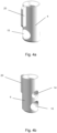
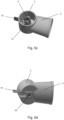
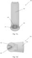
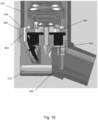
- the mouthpiece 3 is in fluid communication with an external opening of the pMDI 1 surrounding the canister 5.
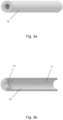
- the pMDI 1 further comprises an open tube whistle 10.
- the open tube whistle is a cylindrical tube which is open at both ends.
- the upright main body 2 and mouthpiece 3 are integrally formed as a single plastic component, and the stem block 4 and open tube whistle 10 are formed as separate components.
- the open tube whistle 10 is insertable into the upright main body 3 such that a first end 10a of the open tube whistle 10 is in fluid communication with the mouthpiece 3, and a second end 10b of the open tube whistle 10 forms an additional external opening of the pMDI 1.
- the second end 10b of the open tube whistle (which provides the additional external opening of the inhaler device 10) is on an opposing lateral side of the upright main body 2 to the mouthpiece 3.
- the second end 10b of the open tube whistle 10, the first end 10a of the open tube whistle and the opening of the mouthpiece 3 are substantially collinear.
- the open tube whistle may have an axial length of between 14 and 18mm.
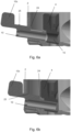
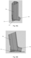
- Figure 3b is a cross-section of the open tube whistle 10 of Figure 3a , which illustrates the outer diameter and inner diameter of the open tube whistle 10.
- the inner cross-sectional profile of the open tube whistle 10 is substantially circular.
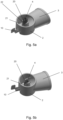
- the inner diameter of the open tube whistle 10 has a stepped profile having a single step between a first portion 11 and a second portion 12.
- the first portion 11 of the open tube whistle 10 has a larger inner diameter than the second portion 12 of the open tube whistle, and the axial length of the first portion 11 of the open tube whistle 10 is greater than the axial length of the second portion 12 of the open tube whistle 10.
- the stepped profile of the inner diameter of the open tube whistle 10 acts as an acoustic impedance within the whistle 10, such that an audible/sound signal is only generated when a predetermined fluid flow rate is generated through the open tube whistle.
- the second portion 12 of the open tube whistle 10 is adjacent to the second end 10b of the open tube whistle which forms the additional external opening of the pMDI 1
- the first portion 11 of the open tube whistle 10 is adjacent to the first end 10a of the open tube whistle 10 (when the open tube whistle is inserted into the pMDI 1).
- the stem block 4 has a passage 15 extending therethrough for receiving the open tube whistle 10.
- the passage 15 is spaced from the drug delivery output aperture 14.
- the stem block 4 also comprises a locating protrusion 20 for correctly positioning the stem block 4 in the main body 2.
- the open tube whistle 10 is in a first position in which only the first end 10a of the open tube whistle is positioned within the pMDI 1.
- the open tube whistle 10 is pushed through the passage 15 of the stem block 4, and into a second position in which the open tube whistle 10 extends through the stem block 4, and the first end 10a of the open tube whistle 4 is in fluid communication with the mouthpiece 3.
- the open tube whistle 10 acts as a locking mechanism to lock the stem block 4 to the upright main body 2, by extending all the way through the stem block 4.
- the open tube whistle 10 is therefore incorporated as a sliding locking component to engage and disengage the removable stem block 4 from the main body 2.
- the open tube whistle 10 extends through the passage 15 in the stem block 4 to lock the stem block 4 to the main body 2.
- the stem block 4 is biased into the second position by a second projection 25 on the open tube whistle 10 with a snap-fit fitting. Specifically, the second projection 25 holds the open tube whistle 10 in the second position.
- the open tube whistle 10 may be biased into the second position by a spring loaded mechanism.
- the handle tab 10c is used by the user to slide the open tube whistle 10 between the first position and the second position.
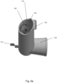
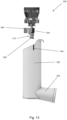
- FIG 7 shows a pMDI 100 which is very similar to the pMDI 1 shown in Figure 1 .
- pMDI 100 is the same as pMDI 1 shown in Figure 1 , except for that the stem block 104 has a stem block guider 140 for guiding the stem block 104 into the stem block receiving portion 121 (see e.g. Figure 9b ) in the main body 102.
- the open tube whistle 110 is moved from the second position in which the open tube whistle 110 locks the stem block 104 into the stem block receiving portion 121, back into the first position in which the open tube whistle 110 does not extend through the stem block 104. Then, a user may push the stem block 104 out of the stem block receiving portion 121 via an opening 123 in an underside of the main body 102.
- Ribs 141 in the main body 102 of pMDI 100 have multiple uses. Ribs 141 can be used to help locate and guide drug canister 105 (shown in Figure 7 ), and specifically a canister valve stem of the drug canister 105, into the stem block 104. Ribs 141 can also be used to add strength to the main body 102. Furthermore, ribs 141 can also be used to guide the stem block into a correct position/orientation for interlocking with the open tube whistle.
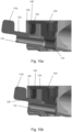
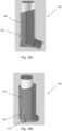
- Figures 10a and 10b correspond to Figures 6a and 6b respectively. Figure 10a shows the open tube whistle 110 of pMDI in the first position, and Figure 10b shows the open tube whistle 110 in the second position.
- the open tube whistle 110 may be biased into the second position by a spring loaded mechanism.
- pMDI 300 is illustrated in Figure 13 , and is similar to pMDI 100. Therefore, like reference numerals are shown. pMDI 300 differs from pMDI 100 in that stem block guider 340 comprises a location indicating feature 344. Main body 302 of pMDI 300 comprises a corresponding location indicating feature 345. The location indicating feature 345 on the main body 302 is located at an end of the main body 302 distal to mouthpiece 303, and is located on an external surface of the main body 302 (although in other embodiments, the location indicating feature 345 may be located on an internal surface of the main body).
- the location indicating features 344, 345 may help a user to correctly align the stem block 304 in a correct orientation in the main body 302, and specifically in the stem block receiving portion of the main body 302.
- the correct orientation may be an orientation in which an open tube whistle (such as open tube whistle 10, 110 described above) may be inserted into the main body through passage 315 in the stem block 304.
- a user may align the location indicating features 344, 345 on the stem block guider 340 and main body 302 in order to position the stem block 304 in the main body 302 in the correct orientation.
- only one of the stem block guider and the main body may have a location indicating feature.
- the location indicating features 344, 345 on the stem block guider 340 and main body 302 comprise visual location indicating features.
- the visual location indicating features 344, 345 are colour coded (e.g. have the same colour) and are manufactured by injection moulding (e.g. two shot injection moulding).
- the visual location indicating features 344, 345 may comprise stickers.
- the location indicating features may comprise protrusions and corresponding cut-outs, or may be formed from portions of the stem block guider/main body having a different surface texture to the remaining portion of the stem block guider/main body, or may comprise the Braille tactile reading and writing system.
- a majority of the stem block guider may have a smooth surface texture
- the location indicating features may have a rough surface texture.
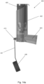
- FIGs 14a-14c illustrate a pMDI 400 which is similar to pMDIs 1, 100, 300 and so like reference numerals are shown.
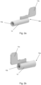
- pMDI 400 additional comprises a mouthpiece cap 446 which is tethered to the open tube whistle 410.
- mouthpiece cap 446 can cover the entire opening in the mouthpiece 403 to ensure the opening in the mouthpiece 403 remains clean when not in use.
- the mouthpiece cap 446 cannot be lost when removed from the mouthpiece 403.
- open tube whistle 410 cannot be lost from the main body 402 when the mouthpiece cap 446 is positioned over the mouthpiece 403.
- Mouthpiece cap 446 is attached to open tube whistle 410 via tether 447, which is formed integrally with the mouthpiece cap 446.
- the tether 447 and mouthpiece cap 446 may be formed as separate components.
- the length of the open tube whistle is extended compared to that shown in 6a and 6b, for example. Accordingly, open tube whistle 410 may generate an audible/sound signal with a lower frequency than the audible/sound signal generated by open tube whistle 10 shown in Figures 6a and 6b .
- open tube whistle 410 is reversibly receivable in the stem block 404, as described above with reference to Figures 6a and 6b .
- Figures 15a-d illustrate an alternative embodiment in which the mouthpiece cap 446 and the open tube whistle 410 (and tether 447) are integrally formed as a single component, but stem block 404 is formed as a separate component. Main body 402 is also manufactured as a separate component.
- open tube whistle 410 is reversibly receivable in stem block 404.
- Figures 15c and 15d show the open tube whistle 410, tether 447 and open tube whistle 410 integrally formed as a single component.
- Figures 17a and 17b illustrate embodiments of the inhaler device in which a counter 550 is arranged within the main body 502 of pMDI 500.
- the counter 550, open tube whistle 510, main body 502 and stem block 504 are formed as separate components.
- the open tube whistle 510 is slidably and reversibly receivable in the counter 510.
- the open tube whistle 510 extends through the counter 550 in order to lock the counter 550 to the main body 502.
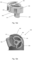
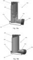
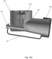
- Figures 18a-f and Figure 19 illustrate further embodiments of an inhaler device having a counter 650 arranged within the main body 602 of pMDI 600.
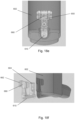
- the inhaler device further comprises a magnifying lens 660 arranged to enhance the visibility of the counter 650 arranged within the main body 602.
- the magnifying lens 660 magnifies the number of actuations of the pMDI displayed on the counter 650, as best shown in Figure 18e .
- the magnifying lens 660, open tube whistle 610 and stem block 604 are integrally formed as a single component that can be slidably received in the main body 602 by a snap-fit connection.
- bumps and/or tapers 664 i.e. angled faces
- bumps may be located on the magnifying lens 660 to provide a snap-fit (e.g.
- the main body 602 may be chamfered to guide the single component formed from the magnifying lens 660, open tube whistle 610 and stem block 604 thereinto.
- the single component formed from the magnifying lens 660, open tube whistle 610 and stem block 604 and/or the main body 602 may have angled or tapered faces to provide an interference fit when the single component is slidably received in the main body 602.
- a pair of assembly tabs 662 are formed either side of the magnifying lens 660 to aid the insertion and removal of the single component from the main body 602. As best shown in Figure 19 , a stop face 666 of the main body 602 ensures that the open tube whistle 610 is correctly positioned inside the main body 602.
- Figures 21a-21h illustrate various possible cross-sectional profiles of open tube whistle 1010 which may be incorporated into any of the pMDIs described above, or any of the oral mask assemblies described below.
- Figures 22a-22h corresponds to Figures 21a-21h respectively, with exaggerated cross-sectional profiles.
- the open tube whistle 1010 of Figure 21a has angled internal step faces 1052, but flat external step faces 1054.
- the angled internal step faces 1052 are angled outwardly such that the second portion 1012 of the open tube whistle 1010 has a greater axial length at a region closer to a central longitudinal axis of the open tube whistle 1010 than at a region further from a central longitudinal axis of the open tube whistle 1010.
- the open tube whistle 1010 of Figure 21b has both angled internal step faces 1052 and angled external step faces 1054.
- the angled internal and external step faces 1054 are both angled outwardly such that the second portion 1012 of the open tube whistle 1010 has a greater axial length at a region closer to a central longitudinal axis of the open tube whistle 1010 than at a region further from a central longitudinal axis of the open tube whistle 1010.
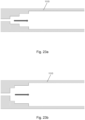
- Figure 21g illustrates an open tube whistle 1010, wherein the inner diameter of the first portion 1011 of the open tube whistle 1010 tapers along its axial length. Specifically, the inner diameter of the first portion 1011 of the open tube whistle 1010 tapers towards the second portion 1012 of the open tube whistle 1010.
- alternative open tube whistles may be formed such that an inner diameter of the first portion of the open tube whistle tapers away from the second portion of the open tube whistle.
- Figure 21h illustrates an open tube whistle 1010, wherein the first end of the open tube whistle 1010 (for fluid communication with the mouthpiece), and adjacent the first portion 1011 of the open tube whistle 1010 is non-planar.
- the first end of the open tube whistle 1010 is concave.
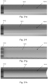
- Figures 23a and 23b illustrate cross-sectional profiles of open tube whistle 1110 which may be incorporated into any of the pMDIs described above, or any of the oral mask assemblies described below.
- the stepped profile of open tube whistle 1110 comprises a plurality of steps.
- each step has a similar height and width (e.g. relative to neighbouring steps), whereas in Figure 23b , the steps have different heights and widths (e.g. relative to neighbouring steps).
- the height and width of the steps may be chosen to generate sound with a specific (e.g. preferred) frequency.
- the arrows in Figures 23a and 23b indicate the direction of fluid (e.g. air) flow through the open tube whistle 1110, in use.
- the audible/sound signal generated by open tube whistle 10, 110, 210, 310, 410, 510, 610 may be detectable by a sound receiver on a mobile device, such as a mobile phone.
- the mobile device may be configured to monitor, record and/or analyse the fluid flow rate through the open tube whistle and/or breathing patterns based on the frequencies/harmonics of the audible/sound signal detected by the sound receiver.
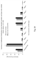
- Figure 24 is a graph showing a comparison of the performance of an inhaler device comprising an open tube whistle (labelled as “OTW”), with an inhaler device without an open tube whistle (labelled as “Ventolin Inhaler”), based on experimental data from experiments conducted by the inventors.
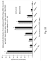
- Figure 25 is a graph showing a comparison of the performance of a pMDI comprising a salbutamol/HFA152a formulation, and an integral stem block and open tube whistle (labelled as "SB+OTW”) with a standard pMDI comprising a salbutamol/HFA152a formulation (labelled as "CONTROL”), based on experimental data from experiments conducted by the inventors.
- performance of the inhaler device is not unduly compromised by the presence of an open tube whistle. Therefore, the presence of the open tube whistle, which provides feedback to the user that they have the correct inhalation technique, does not unduly affect the performance of the inhaler device to deliver an active ingredient/drug to a user.
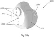
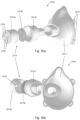
- FIGS 26a-26d show different views of an oral mask assembly 2000.
- the oral mask assembly 2000 comprises a breathing mask 2002 which is configured to be worn by a user so that the breathing mask 2002 covers the mouth and nose of the user.
- the oral mask assembly 2000 comprises strap loop buckles 2010 for attaching to a strap for fixing the breathing mask 2002 to the user's face.
- a main body 2012 of the breathing mask 2002 is injection moulded from a polymer material such as PVC, ABS or PP, and a rim of the main body 2012 is lip-shaped and comprises rubber, a plastic/polymer, silicone and/or foam (e.g. Polyvinyl Chloride, PVC), for providing a tight and comfortable seal with the user's face.
- PVC Polyvinyl Chloride
- the oral mask assembly 2000 comprises two one-way valves 2020a, 2020b, one for user inhalation and the other for user exhalation.
- the one-way valves 2020a, 2020b are attachable to the main body 2012 of the breathing mask 2002 in a pair of valve receiving recesses 2022 by way of a snap-fit connection.
- the valve receiving recesses 2022 are formed on an internal side 2004 of the main body 2012 of the breathing mask 2002.
- Each valve receiving recess 2022 comprises a bypass channel 2024a, 2024b, as best shown in Figure 26c .
- each of the one-way valves 2020a, 2020b is in fluid communication with a respective bypass channel 2024a, 2024b.
- the inner diameter of the bypass channels 2024a, 2024b are different.
- the inner diameter of the bypass channel 2024b in fluid communication with the one-way valve 2020b for user exhalation is greater than the inner diameter of the bypass channel 2024a in fluid communication with the one-way valve 202a for user inhalation 2020a.
- the one-way valves 2020a, 2020b may comprise a filter, such as an antimicrobial medical grade filter.
- a filter may be attachable to each of the one-way valves, and may be configured to be fitted to the respective one-way valve adjacent to the internal side 2004 and/or the external side 2006 of the breathing mask 2002.
- the stepped profiles of the two open tube whistles 2030a for user inhalation may have the same/similar or different dimensions or geometries (as described above) to each other, such that the two open tube whistles 2030a generate an audible/sound signal at different predetermined fluid flow rates.
- An inner diameter of a first portion of the open tube whistles 2030a for user inhalation is greater than an inner diameter of a second portion of the open tube whistles 2030a for user inhalation.
- the first portion having the greater diameter of each open tube whistle 2030a for user inhalation is provided in fluid communication and adjacent to the internal side 2004 of the breathing mask 2002.
- the second portion having the smaller inner diameter of each open tube whistle 2030a for user inhalation is provided in fluid communication and adjacent to the external side 2006 of the breathing mask 2002.
- the arrows indicate the air flow path through a second one-way valve 2020b which opens to permit fluid flow from the internal side 2004 to the external side 2006 of the breathing mask 2002 as the user exhales (but prohibits air flow in the other direction by closing when the user inhales).
- air also flows through two open tube whistles 2030b, which each generate an audible/sound signal at a specific rate of air flow during user exhalation.
- the stepped profiles of the two open tube whistles 2030b for user exhalation may have different dimensions or geometries (as described above), such that the two open tube whistles 2030b generate an audible/sound signal at different predetermined fluid flow rates during user exhalation.
- the first portions of the open tube whistles 2030a, 2030b having the greater inner diameter are downstream (i.e. in the direction of fluid flow) from the second portions of the open tube whistle having the smaller inner diameter.
- Oral mask assembly 2100 comprises two open tube whistles 2130a, 2130b, a first open tube whistle 2130a for generating an audible/sound signal during user inhalation, and the other open tube whistle 2130b for generating an audible/sound signal during user exhalation.
- the open tube whistle 2130a for generating an audible/sound signal during user inhalation has a first portion with a greater inner diameter in fluid communication with, and adjacent to, the internal side 2004 of the breathing mask 2102, and a second portion with a smaller inner diameter in fluid communication with, and adjacent to, the external side 2006 of the breathing mask 2102.
- the open tube whistle 2130b for generating an audible/sound signal during user exhalation has a first portion with a greater inner diameter in fluid communication with, and adjacent to, the external side 2006 of the breathing mask 2102, and a second portion with a smaller inner diameter in fluid communication with, and adjacent to, the internal side 2004 of the breathing mask 2102.
- Providing the open tube whistles 2230 in a replaceable sub-component 2214 means that the open tube whistles can be replaced with open-tube whistles of different geometries and/or dimensions which may thus generate an audible/sound signal at a different predetermined rate of fluid flow.
- a single main body 2212 may be (re)usable with different combinations of open tube whistles, whereas one or more of the sub-components 2214a, 2214b, 2214c may be discarded and/or replaced after use.
Landscapes
- Health & Medical Sciences (AREA)
- Engineering & Computer Science (AREA)
- Animal Behavior & Ethology (AREA)
- Anesthesiology (AREA)
- Biomedical Technology (AREA)
- Heart & Thoracic Surgery (AREA)
- Hematology (AREA)
- Life Sciences & Earth Sciences (AREA)
- General Health & Medical Sciences (AREA)
- Public Health (AREA)
- Veterinary Medicine (AREA)
- Pulmonology (AREA)
- Bioinformatics & Cheminformatics (AREA)
- Vascular Medicine (AREA)
- Infusion, Injection, And Reservoir Apparatuses (AREA)
Claims (14)
- Inhaliervorrichtung (1) zum Angeben einer gewünschten Fluidströmungsrate, wobei die Vorrichtung Folgendes umfasst:eine offene Rohrpfeife (10); undein Mundstück (3), das in Fluidkommunikation mit einer äußeren Öffnung der Inhaliervorrichtung und einem ersten Ende der offenen Rohrpfeife (10a) steht, wobei ein Innendurchmesser der offenen Rohrpfeife ein Stufenprofil aufweist, sodass beim Inhalieren über das Mundstück durch einen Benutzer bei einer vorbestimmten Fluidströmungsrate über die offene Rohrpfeife ein hörbares/Klangsignal erzeugt wird, wobei:das Stufenprofil des Innendurchmessers der offenen Rohrpfeife nur eine Stufe umfasst;die Stufe näher bei einem zweiten Ende (10b) der offenen Rohrpfeife als beim ersten Ende der offenen Rohrpfeife angeordnet ist; dadurch gekennzeichnet, dassder Innendurchmesser eines zum ersten Ende der offenen Rohrpfeife benachbarten ersten Abschnitts der offenen Rohrpfeife größer ist als der Innendurchmesser eines zum zweiten Ende der offenen Rohrpfeife benachbarten zweiten Abschnitts der offenen Rohrpfeife.
- Inhaliervorrichtung nach Anspruch 1, wobei das zweite Ende (10b) der offenen Rohrpfeife eine zusätzliche äußere Öffnung der Inhaliervorrichtung bereitstellt.
- Inhaliervorrichtung nach Anspruch 2, wobei das zweite Ende der offenen Rohrpfeife, das erste Ende der offenen Rohrpfeife und eine Öffnung des Mundstücks zur Kommunikation mit dem Mund des Benutzers kollinear sind.
- Inhaliervorrichtung nach Anspruch 2 oder 3, wobei eine Seitenwand der offenen Rohrpfeife zumindest ein seitliches Loch definiert.
- Inhaliervorrichtung nach einem der Ansprüche 2 bis 4, ferner umfassend einen Schaftblock (4) zum Anordnen eines Arzneimittelreservoirs (5), wobei das Arzneimittelreservoir betreibbar ist, um eine Arzneimitteldosis über eine Arzneimittelabgabeausgangsöffnung (14) in das Mundstück zum Inhalieren durch den Benutzer abzugeben, wobei die offene Rohrpfeife sich zur Fluidkommunikation mit dem Mundstück durch den Schaftblock hindurch erstreckt.
- Inhaliervorrichtung nach Anspruch 5, wobei der Schaftblock und die offene Rohrpfeife einstückig ausgebildet sind, und gegebenenfalls ferner umfassend einen aufrechten Hauptkörper (2) zum Aufnehmen des Arzneimittelreservoirs, wobei der aufrechte Hauptkörper, der Schaftblock und die offene Rohrpfeife einstückig ausgebildet sind.
- Inhaliervorrichtung nach Anspruch 5, wobei die offene Rohrpfeife umkehrbar und gleitend im Schaftblock aufnehmbar ist.
- Inhaliervorrichtung nach Anspruch 7, ferner umfassend einen aufrechten Hauptkörper (2) zum Aufnehmen des Arzneimittelreservoirs, wobei der Schaftblock umkehrbar und gleitend im aufrechten Hauptkörper aufnehmbar ist, und wobei die offene Rohrpfeife dazu ausgelegt ist, sich durch den Schaftblock hindurch zu erstrecken, um den Schaftblock mit dem aufrechten Hauptkörper zu verriegeln.
- Inhaliervorrichtung nach Anspruch 8, wobei der aufrechte Hauptkörper ein Anordnungsmerkmal umfasst und der Schaftblock ein Anordnungsmerkmal umfasst, wobei das Anordnungsmerkmal des Schaftblocks das Anordnungsmerkmal des Hauptkörpers ergänzt, um den Schaftblock korrekt im aufrechten Hauptkörper zu positionieren, und wobei gegebenenfalls das Anordnungsmerkmal des Schaftblocks ein Anordnungsvorsprung ist und das Anordnungsmerkmal des Hauptkörpers eine Anordnungsaussparung ist, wobei der Anordnungsvorsprung des Schaftblocks dazu ausgelegt ist, mit der Anordnungsaussparung des Hauptkörpers in Eingriff zu gelangen.
- Inhaliervorrichtung nach Anspruch 8 oder 9, fermer umfassend ein Schaftblockführungselement (140) zum Führen des Schaftblocks entlang einer oder mehrerer hervorstehender Rippen (141) im aufrechten Hauptkörper, und wobei das Schaftblockführungselement gegebenenfalls mit dem Schaftblock einstückig ausgebildet ist.
- Inhaliervorrichtung nach Anspruch 7 bis 10, wobei die offene Rohrpfeife in eine zusammengesetzte Position vorgespannt ist, in welcher sich die offene Rohrpfeife durch den Schaftblock hindurch erstreckt.
- Inhaliervorrichtung nach einem der vorangegangenen Ansprüche, wobei die Inhaliervorrichtung ein Abstandselement ist.
- Inhaliervorrichtung nach einem der Ansprüche 1 bis 11, wobei:die Inhaliervorrichtung ein druckbeaufschlagtes Dosierinhaliergerät (pMDI) ist; oderdie Inhaliervorrichtung eine Arzneimittelabgabeinhaliervorrichtung ist, welche eine Salbutamol/HFA-152a-Formulierung umfasst.
- System, umfassend eine Inhaliervorrichtung nach einem der vorangegangenen Ansprüche und eine Computervorrichtung, die einen Klangempfänger zum Detektieren des hörbaren/Klangsignals aufweist.
Applications Claiming Priority (3)
| Application Number | Priority Date | Filing Date | Title |
|---|---|---|---|
| GB1917420.0A GB2589369A (en) | 2019-11-29 | 2019-11-29 | Device with flow rate indicator |
| GB2006647.8A GB2589395A (en) | 2019-11-29 | 2020-05-05 | Device with flow rate indicator |
| PCT/EP2020/081803 WO2021104880A1 (en) | 2019-11-29 | 2020-11-11 | Device with flow rate indicator |
Publications (3)
| Publication Number | Publication Date |
|---|---|
| EP4065197A1 EP4065197A1 (de) | 2022-10-05 |
| EP4065197C0 EP4065197C0 (de) | 2025-04-16 |
| EP4065197B1 true EP4065197B1 (de) | 2025-04-16 |
Family
ID=69147214
Family Applications (1)
| Application Number | Title | Priority Date | Filing Date |
|---|---|---|---|
| EP20804545.0A Active EP4065197B1 (de) | 2019-11-29 | 2020-11-11 | Vorrichtung mit durchflussratenanzeiger |
Country Status (3)
| Country | Link |
|---|---|
| EP (1) | EP4065197B1 (de) |
| GB (2) | GB2589369A (de) |
| WO (1) | WO2021104880A1 (de) |
Families Citing this family (2)
| Publication number | Priority date | Publication date | Assignee | Title |
|---|---|---|---|---|
| EP4515563A1 (de) * | 2022-04-25 | 2025-03-05 | Sonohaler ApS | Elektronische vorrichtung zur charakterisierung und/oder überwachung einer inhalation und/oder einer ausatmung mit einer inhalatorvorrichtung, zugehöriges system und verfahren |
| US20250345534A1 (en) * | 2022-04-25 | 2025-11-13 | Sonohaler Aps | An electronic device for characterizing and/or monitoring an operation of an inhaler device, related system and method |
Citations (1)
| Publication number | Priority date | Publication date | Assignee | Title |
|---|---|---|---|---|
| EP2560720B1 (de) * | 2010-04-22 | 2017-08-02 | Omar Mian | Gasflussanzeiger |
Family Cites Families (9)
| Publication number | Priority date | Publication date | Assignee | Title |
|---|---|---|---|---|
| ES226342Y (es) * | 1977-02-11 | 1977-08-01 | Dispositivo de aviso sonoro para aplicacion de aerosoles. | |
| US6039042A (en) * | 1998-02-23 | 2000-03-21 | Thayer Medical Corporation | Portable chamber for metered dose inhaler dispensers |
| GB2372704B (en) | 2001-01-05 | 2004-06-09 | Clement Clarke Int Ltd | Respiratory flow rate determination |
| JP2004195191A (ja) * | 2002-10-22 | 2004-07-15 | Akihiko Miyamoto | 呼子付喘息治療薬吸入器 |
| GB201107103D0 (en) | 2011-04-27 | 2011-06-08 | Clement Clarke Int Ltd | Improvements in drug delivery inhaler devices |
| US20120318261A1 (en) * | 2011-06-17 | 2012-12-20 | Nostrum Technology Llc | Valved Holding Chamber With Whistle for the Administration of Inhalable Drugs |
| WO2014053242A1 (de) * | 2012-10-04 | 2014-04-10 | Boehringer Ingelheim International Gmbh | System, verfahren und verwendung zum trainieren eines inhalationsvorgangs |
| WO2017049034A1 (en) * | 2015-09-18 | 2017-03-23 | Leydon Krispin Johan | Systems, devices and methods for rendering key respiratory measurements accessible to mobile digital devices |
| GB2547549B (en) * | 2016-02-15 | 2021-08-11 | Clement Clarke International Ltd | Device with flow rate indicator |
-
2019
- 2019-11-29 GB GB1917420.0A patent/GB2589369A/en not_active Withdrawn
-
2020
- 2020-05-05 GB GB2006647.8A patent/GB2589395A/en not_active Withdrawn
- 2020-11-11 WO PCT/EP2020/081803 patent/WO2021104880A1/en not_active Ceased
- 2020-11-11 EP EP20804545.0A patent/EP4065197B1/de active Active
Patent Citations (1)
| Publication number | Priority date | Publication date | Assignee | Title |
|---|---|---|---|---|
| EP2560720B1 (de) * | 2010-04-22 | 2017-08-02 | Omar Mian | Gasflussanzeiger |
Also Published As
| Publication number | Publication date |
|---|---|
| GB202006647D0 (en) | 2020-06-17 |
| EP4065197C0 (de) | 2025-04-16 |
| GB2589369A (en) | 2021-06-02 |
| WO2021104880A1 (en) | 2021-06-03 |
| GB2589395A (en) | 2021-06-02 |
| GB201917420D0 (en) | 2020-01-15 |
| EP4065197A1 (de) | 2022-10-05 |
Similar Documents
| Publication | Publication Date | Title |
|---|---|---|
| US20240424243A1 (en) | Flow Sensor for Ventilation | |
| EP2521583B1 (de) | Feedback- und compliancevorrichtung für einen inhalator | |
| EP2618876B1 (de) | Mit einem ventil versehene kammer mit einem ventilhaltesysstem | |
| US4291688A (en) | Inhalation device | |
| EP4065197B1 (de) | Vorrichtung mit durchflussratenanzeiger | |
| JP2015530201A (ja) | 呼吸マスク | |
| US20230241331A1 (en) | Inhaler with acoustic flow monitoring | |
| CN108697871B (zh) | 具有流动速率指示器的装置 | |
| US11577033B2 (en) | Valved spacer for inhalation device | |
| CA2826516A1 (en) | Flow measuring apparatus and inhalation apparatus comprising the same | |
| US20220203049A1 (en) | System, inhaler, and method of monitoring | |
| US20200197635A1 (en) | Device with flow rate indicator | |
| EP4205645A1 (de) | Mundstückanordnung für eine atemmessvorrichtung | |
| GB2547549A (en) | Device with flow rate indicator | |
| EP3682923B1 (de) | Medikamenteninhalator zur aerosolpulmonalen verabreichung mit visuellem feedback-system | |
| GB2520779A (en) | Improvements in drug delivery inhaler devices | |
| US20200146591A1 (en) | Device with flow rate indicator |
Legal Events
| Date | Code | Title | Description |
|---|---|---|---|
| STAA | Information on the status of an ep patent application or granted ep patent |
Free format text: STATUS: UNKNOWN |
|
| STAA | Information on the status of an ep patent application or granted ep patent |
Free format text: STATUS: THE INTERNATIONAL PUBLICATION HAS BEEN MADE |
|
| PUAI | Public reference made under article 153(3) epc to a published international application that has entered the european phase |
Free format text: ORIGINAL CODE: 0009012 |
|
| STAA | Information on the status of an ep patent application or granted ep patent |
Free format text: STATUS: REQUEST FOR EXAMINATION WAS MADE |
|
| 17P | Request for examination filed |
Effective date: 20220617 |
|
| AK | Designated contracting states |
Kind code of ref document: A1 Designated state(s): AL AT BE BG CH CY CZ DE DK EE ES FI FR GB GR HR HU IE IS IT LI LT LU LV MC MK MT NL NO PL PT RO RS SE SI SK SM TR |
|
| DAV | Request for validation of the european patent (deleted) | ||
| DAX | Request for extension of the european patent (deleted) | ||
| STAA | Information on the status of an ep patent application or granted ep patent |
Free format text: STATUS: EXAMINATION IS IN PROGRESS |
|
| 17Q | First examination report despatched |
Effective date: 20240311 |
|
| GRAP | Despatch of communication of intention to grant a patent |
Free format text: ORIGINAL CODE: EPIDOSNIGR1 |
|
| STAA | Information on the status of an ep patent application or granted ep patent |
Free format text: STATUS: GRANT OF PATENT IS INTENDED |
|
| GRAJ | Information related to disapproval of communication of intention to grant by the applicant or resumption of examination proceedings by the epo deleted |
Free format text: ORIGINAL CODE: EPIDOSDIGR1 |
|
| STAA | Information on the status of an ep patent application or granted ep patent |
Free format text: STATUS: EXAMINATION IS IN PROGRESS |
|
| INTG | Intention to grant announced |
Effective date: 20241016 |
|
| GRAP | Despatch of communication of intention to grant a patent |
Free format text: ORIGINAL CODE: EPIDOSNIGR1 |
|
| STAA | Information on the status of an ep patent application or granted ep patent |
Free format text: STATUS: GRANT OF PATENT IS INTENDED |
|
| INTC | Intention to grant announced (deleted) | ||
| INTG | Intention to grant announced |
Effective date: 20241122 |
|
| RAP1 | Party data changed (applicant data changed or rights of an application transferred) |
Owner name: FLEXICARE (GROUP) LIMITED |
|
| GRAS | Grant fee paid |
Free format text: ORIGINAL CODE: EPIDOSNIGR3 |
|
| GRAA | (expected) grant |
Free format text: ORIGINAL CODE: 0009210 |
|
| STAA | Information on the status of an ep patent application or granted ep patent |
Free format text: STATUS: THE PATENT HAS BEEN GRANTED |
|
| AK | Designated contracting states |
Kind code of ref document: B1 Designated state(s): AL AT BE BG CH CY CZ DE DK EE ES FI FR GB GR HR HU IE IS IT LI LT LU LV MC MK MT NL NO PL PT RO RS SE SI SK SM TR |
|
| REG | Reference to a national code |
Ref country code: GB Ref legal event code: FG4D |
|
| REG | Reference to a national code |
Ref country code: CH Ref legal event code: EP |
|
| REG | Reference to a national code |
Ref country code: IE Ref legal event code: FG4D |
|
| REG | Reference to a national code |
Ref country code: DE Ref legal event code: R096 Ref document number: 602020049625 Country of ref document: DE |
|
| U01 | Request for unitary effect filed |
Effective date: 20250501 |
|
| U07 | Unitary effect registered |
Designated state(s): AT BE BG DE DK EE FI FR IT LT LU LV MT NL PT RO SE SI Effective date: 20250509 |
|
| PG25 | Lapsed in a contracting state [announced via postgrant information from national office to epo] |
Ref country code: ES Free format text: LAPSE BECAUSE OF FAILURE TO SUBMIT A TRANSLATION OF THE DESCRIPTION OR TO PAY THE FEE WITHIN THE PRESCRIBED TIME-LIMIT Effective date: 20250416 |
|
| PG25 | Lapsed in a contracting state [announced via postgrant information from national office to epo] |
Ref country code: NO Free format text: LAPSE BECAUSE OF FAILURE TO SUBMIT A TRANSLATION OF THE DESCRIPTION OR TO PAY THE FEE WITHIN THE PRESCRIBED TIME-LIMIT Effective date: 20250716 Ref country code: GR Free format text: LAPSE BECAUSE OF FAILURE TO SUBMIT A TRANSLATION OF THE DESCRIPTION OR TO PAY THE FEE WITHIN THE PRESCRIBED TIME-LIMIT Effective date: 20250717 |
|
| PG25 | Lapsed in a contracting state [announced via postgrant information from national office to epo] |
Ref country code: PL Free format text: LAPSE BECAUSE OF FAILURE TO SUBMIT A TRANSLATION OF THE DESCRIPTION OR TO PAY THE FEE WITHIN THE PRESCRIBED TIME-LIMIT Effective date: 20250416 |
|
| PG25 | Lapsed in a contracting state [announced via postgrant information from national office to epo] |
Ref country code: HR Free format text: LAPSE BECAUSE OF FAILURE TO SUBMIT A TRANSLATION OF THE DESCRIPTION OR TO PAY THE FEE WITHIN THE PRESCRIBED TIME-LIMIT Effective date: 20250416 |
|
| PG25 | Lapsed in a contracting state [announced via postgrant information from national office to epo] |
Ref country code: RS Free format text: LAPSE BECAUSE OF FAILURE TO SUBMIT A TRANSLATION OF THE DESCRIPTION OR TO PAY THE FEE WITHIN THE PRESCRIBED TIME-LIMIT Effective date: 20250716 |
|
| PG25 | Lapsed in a contracting state [announced via postgrant information from national office to epo] |
Ref country code: IS Free format text: LAPSE BECAUSE OF FAILURE TO SUBMIT A TRANSLATION OF THE DESCRIPTION OR TO PAY THE FEE WITHIN THE PRESCRIBED TIME-LIMIT Effective date: 20250816 |