EP4064597B1 - Verfahren und vorrichtung zum handhaben von unkontinuierlichem empfang in einem kommunikationsnetz - Google Patents
Verfahren und vorrichtung zum handhaben von unkontinuierlichem empfang in einem kommunikationsnetz Download PDFInfo
- Publication number
- EP4064597B1 EP4064597B1 EP22166787.6A EP22166787A EP4064597B1 EP 4064597 B1 EP4064597 B1 EP 4064597B1 EP 22166787 A EP22166787 A EP 22166787A EP 4064597 B1 EP4064597 B1 EP 4064597B1
- Authority
- EP
- European Patent Office
- Prior art keywords
- wake
- message
- drx
- time
- network node
- Prior art date
- Legal status (The legal status is an assumption and is not a legal conclusion. Google has not performed a legal analysis and makes no representation as to the accuracy of the status listed.)
- Active
Links
Images


Classifications
-
- H—ELECTRICITY
- H04—ELECTRIC COMMUNICATION TECHNIQUE
- H04L—TRANSMISSION OF DIGITAL INFORMATION, e.g. TELEGRAPHIC COMMUNICATION
- H04L1/00—Arrangements for detecting or preventing errors in the information received
- H04L1/12—Arrangements for detecting or preventing errors in the information received by using return channel
- H04L1/16—Arrangements for detecting or preventing errors in the information received by using return channel in which the return channel carries supervisory signals, e.g. repetition request signals
- H04L1/18—Automatic repetition systems, e.g. Van Duuren systems
- H04L1/1812—Hybrid protocols; Hybrid automatic repeat request [HARQ]
-
- H—ELECTRICITY
- H04—ELECTRIC COMMUNICATION TECHNIQUE
- H04L—TRANSMISSION OF DIGITAL INFORMATION, e.g. TELEGRAPHIC COMMUNICATION
- H04L1/00—Arrangements for detecting or preventing errors in the information received
- H04L1/12—Arrangements for detecting or preventing errors in the information received by using return channel
- H04L1/16—Arrangements for detecting or preventing errors in the information received by using return channel in which the return channel carries supervisory signals, e.g. repetition request signals
- H04L1/18—Automatic repetition systems, e.g. Van Duuren systems
- H04L1/1829—Arrangements specially adapted for the receiver end
-
- H—ELECTRICITY
- H04—ELECTRIC COMMUNICATION TECHNIQUE
- H04W—WIRELESS COMMUNICATION NETWORKS
- H04W52/00—Power management, e.g. Transmission Power Control [TPC] or power classes
- H04W52/02—Power saving arrangements
- H04W52/0209—Power saving arrangements in terminal devices
- H04W52/0212—Power saving arrangements in terminal devices managed by the network, e.g. network or access point is leader and terminal is follower
- H04W52/0216—Power saving arrangements in terminal devices managed by the network, e.g. network or access point is leader and terminal is follower using a pre-established activity schedule, e.g. traffic indication frame
-
- H—ELECTRICITY
- H04—ELECTRIC COMMUNICATION TECHNIQUE
- H04W—WIRELESS COMMUNICATION NETWORKS
- H04W52/00—Power management, e.g. Transmission Power Control [TPC] or power classes
- H04W52/02—Power saving arrangements
- H04W52/0209—Power saving arrangements in terminal devices
- H04W52/0225—Power saving arrangements in terminal devices using monitoring of external events, e.g. the presence of a signal
- H04W52/0229—Power saving arrangements in terminal devices using monitoring of external events, e.g. the presence of a signal where the received signal is a wanted signal
-
- H—ELECTRICITY
- H04—ELECTRIC COMMUNICATION TECHNIQUE
- H04W—WIRELESS COMMUNICATION NETWORKS
- H04W52/00—Power management, e.g. Transmission Power Control [TPC] or power classes
- H04W52/02—Power saving arrangements
- H04W52/0209—Power saving arrangements in terminal devices
- H04W52/0261—Power saving arrangements in terminal devices managing power supply demand, e.g. depending on battery level
- H04W52/0274—Power saving arrangements in terminal devices managing power supply demand, e.g. depending on battery level by switching on or off the equipment or parts thereof
- H04W52/028—Power saving arrangements in terminal devices managing power supply demand, e.g. depending on battery level by switching on or off the equipment or parts thereof switching on or off only a part of the equipment circuit blocks
-
- H—ELECTRICITY
- H04—ELECTRIC COMMUNICATION TECHNIQUE
- H04W—WIRELESS COMMUNICATION NETWORKS
- H04W76/00—Connection management
- H04W76/20—Manipulation of established connections
- H04W76/28—Discontinuous transmission [DTX]; Discontinuous reception [DRX]
-
- Y—GENERAL TAGGING OF NEW TECHNOLOGICAL DEVELOPMENTS; GENERAL TAGGING OF CROSS-SECTIONAL TECHNOLOGIES SPANNING OVER SEVERAL SECTIONS OF THE IPC; TECHNICAL SUBJECTS COVERED BY FORMER USPC CROSS-REFERENCE ART COLLECTIONS [XRACs] AND DIGESTS
- Y02—TECHNOLOGIES OR APPLICATIONS FOR MITIGATION OR ADAPTATION AGAINST CLIMATE CHANGE
- Y02D—CLIMATE CHANGE MITIGATION TECHNOLOGIES IN INFORMATION AND COMMUNICATION TECHNOLOGIES [ICT], I.E. INFORMATION AND COMMUNICATION TECHNOLOGIES AIMING AT THE REDUCTION OF THEIR OWN ENERGY USE
- Y02D30/00—Reducing energy consumption in communication networks
- Y02D30/70—Reducing energy consumption in communication networks in wireless communication networks
Definitions
- the Evolved Packet System also called a Fourth Generation (4G) network
- EPS comprises the Evolved Universal Terrestrial Radio Access Network (E-UTRAN), also known as the Long Term Evolution (LTE) radio access network
- EPC Evolved Packet Core
- SAE System Architecture Evolution
- LTE Long Term Evolution
- LTE Long Term Evolution
- DRX discontinuous reception
- the terminal device When DRX mode is configured in a terminal device, the terminal device is able to turn its receiver off and enter a low-power state, waking for defined (periodic) phases to listen for scheduling messages or other wireless communications. For example, when the terminal device is in a DRX sleep state, it does not need to listen on the physical downlink control channel (PDCCH). When the terminal device is in the DRX active state, it must normally listen on the PDCCH to wait for potential scheduling messages from the network (e.g. from the eNodeB).
- PDCCH physical downlink control channel
- the terminal device is in the DRX active state when any of the conditions specified in section 5.7 is true, that is to say:
- drx-InactivityTimer an inactivity timer started and while this timer is running the terminal device is awake to listen for any scheduling requests.
- the terminal device will go to short DRX sleep, if configured, otherwise the terminal device will go to long DRX sleep.
- Embodiments herein relate to a UE, a network node and methods therein. According to a first aspect of embodiments herein, the object is achieved by a method, performed by a User Equipment (UE), according to independent claim 1.
- UE User Equipment
- the object is achieved by a method, performed by a network node, according to independent claim 5.
- the object is achieved by a User Equipment (UE), according to independent claim 9.
- UE User Equipment
- the object is achieved by a network node according to independent claim 11.
- 3GPP contribution R2-165572 http://www.3gpp.org/ftp/tsg_ran/WG2_RL2/TSGR2_95/Docs/R2-165572.zip ) submitted to the 3GPP RAN WG2 meeting points at a problem in the UE to support connected mode DRX as it is currently defined in 3GPP.
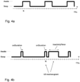
- FIG. 1 shows a typical Connected Mode DRX (C-DRX) operation in E-UTRAN.
- the UE wakes up, which may also be referred to as entering an onDuration, once every DRX cycle to monitor the downlink during its ON duration. If the UE successfully decodes a Physical Downlink Control Channel (PDCCH) for a first transmission, the UE stays awake to receive on the downlink. Following any new data/signaling reception, the UE (re-) starts an inactivity timer. The UE re-enters DRX operation if the inactivity timer expires or if a MAC Control Element (CE) indicating "DRX" is received. In both cases, the DRX cycle that the UE follows after re-entering DRX is given by the following rules:
- Connected Mode DRX is not as power efficient as IDLE Mode DRX (I-DRX). Below a few related aspects are discussed:
- Connected mode DRX is not as power efficient as IDLE Mode DRX (I-DRX). It is however acknowledged that this may be so in some devices, depending on e.g. the implementation etc.
- the problem i.e. the increased power consumption in Connected-DRX, stems from the fact that a legacy UE is required to be able to receive data payload during and immediately following the ON duration, the UE is also expected to decode the data received during the OnDuration and provide HARQ feedback n milliseconds after reception, where n typically corresponds to 4 ms. This consumes more power compared to paging in IDLE state, since the UE immediately has to process the information it receives during the ON duration since there may be data scheduled for the UE. In Idle mode the UE has more time to process the paging channel since the Page response is not required to be sent immediately, it can e.g.
- RACH Random Access Channel
- the UE needs to have more processing hardware (HW) activated which consumes more power.
- HW processing hardware
- the advantage of the Connected mode DRX solution is a shorter delay compared to the IDLE mode procedure, since the UE may receive data immediately. In the IDLE mode procedure however, the UE needs to first send a page response message to the network which adds at least one RTT delay, plus the time it takes to wait for the next RACH slot.
- embodiments herein describe improved methods for handling DRX operation, which may also be referred to as methods for DRX handling, which improves performance and energy consumption of the UE.
- DRX handling improves performance and energy consumption of the UE.
- the UE is in DRX state and is not monitoring certain channels.
- the DRX feature may only put requirements on when the UE shall be "awake”, e.g. be in a non-power-saving-state, and not dictate when the UE shall not be "awake”, e.g. be in a sleeping state or a power-saving-state.
- the UE may be allowed to be in an "awake”/non-power-saving-state all the time, even if the DRX configuration does not require the UE to be in such a state.
- a UE is communicating with a network node, such as an eNB
- a network node such as an eNB
- a network node such as an eNB
- the actions described herein as being performed by the network node may also be performed by a second UE.
- Embodiments herein relate to communication networks in general.
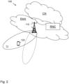
- Fig. 2 is a schematic overview depicting a communication network 100.
- the communication network 100 may be a wireless communications network comprising one or more RANs and one or more CNs.
- the communication network 100 may use a number of different technologies, such as Wi-Fi, Long Term Evolution (LTE), LTE-Advanced, 5G, Wideband Code Division Multiple Access (WCDMA), Global System for Mobile communications/enhanced Data rate for GSM Evolution (GSM/EDGE), Worldwide Interoperability for Microwave Access (WiMax), or Ultra Mobile Broadband (UMB), just to mention a few possible implementations.
- LTE Long Term Evolution
- WCDMA Wideband Code Division Multiple Access
- GSM/EDGE Global System for Mobile communications/enhanced Data rate for GSM Evolution
- WiMax Worldwide Interoperability for Microwave Access
- UMB Ultra Mobile Broadband
- Embodiments herein relate to recent technology trends that are of particular interest in a 5G context
- wireless devices such as e.g. a UE 120.
- wireless device is a nonlimiting term which means any terminal, wireless communication terminal, user equipment, Machine Type Communication (MTC) device, Device to Device (D2D) terminal, or node e.g. smart phone, laptop, mobile phone, sensor, relay, mobile tablets or even a small base station communicating within a cell.
- MTC Machine Type Communication
- D2D Device to Device
- the wireless communication network 100 comprises a network node such as a radio network node 110 providing radio coverage over a geographical area, a service area 11, which may also be referred to as a beam or a beam group where the group of beams is covering the service area of a first radio access technology (RAT), such as 5G, LTE, Wi-Fi or similar.
- the radio network node 110 may be a transmission and reception point e.g. a radio access network node such as a Wireless Local Area Network (WLAN) access point or an Access Point Station (AP STA), an access controller, a base station, e.g.
- WLAN Wireless Local Area Network
- AP STA Access Point Station
- a radio base station such as a NodeB, an evolved Node B (eNB, eNode B), a base transceiver station, a radio remote unit, an Access Point Base Station, a base station router, a transmission arrangement of a radio base station, a stand-alone access point or any other network unit capable of communicating with a wireless device within the service area served by the radio network node 110 depending e.g. on the first radio access technology and terminology used.
- the radio network node 110 may be referred to as a serving radio network node and communicates with the wireless device 120 with Downlink (DL) transmissions to the wireless device 10 and Uplink (UL) transmissions from the wireless device 120.
- DL Downlink
- UL Uplink
- Figure 3 discloses a flowchart depicting embodiments of a method performed by the UE 120, for handling DRX operation.
- Handling DRX shall herein be interpreted as handling the operation of the DRX, such as e.g. handling the duration of the DRX cycles. Actions performed in some embodiments only are marked with dashed boxes.
- Action 301 the UE 120 may receive a message comprising information regarding actions to be delayed from a network node 110.
- the message may comprise only an indication that actions may be delayed.
- the actions to apply the delay to may be specified in a specification.
- the message may however also comprise information about e.g. which action or which actions to apply the delay to, the amount of time the action(s) should be delayed, which may also be referred to as delay duration, and/or conditions for when the delays should be applied.
- the conditions may e.g. be the type of DRX-cycle the UE applies, see also "Conditional applying of behaviors".
- the action may be a decoding of a received signal
- the information may e.g. comprise a decoding delay to be applied to signals received by the UE 120 during a predetermined first time period from the entering of an active state.
- the active state may be a semi-awake state in which the UE listens for a specific signal which may be received using only a part of a radio unit.
- the specific signal may e.g. be a signal which is easy to decode.
- the active state may in some embodiments e.g. be a DRX onDuration period.
- the action may also be an exiting of a DRX state and the information may comprise an indication that the UE 120 shall exit an inactive state.
- the information may further comprise a time period within which the UE 120 is required to exit an inactive state.
- the UE 120 may receive data and/or signaling when the UE has entered an active state.
- Action 303 The UE 120 applies a delay for at least one action performed as a response to data and/or signaling received by the UE 120 during a predefined first time period T A after the UE 120 has entered an active state, which in Example embodiment C, that will be described in the following, is referred to as that the UE woke up recently.
- T A a predefined first time period
- the UE 120 may apply the delay according to information comprised in the message received from the network node 110.
- the action may be a decoding of a received signal.
- the UE 120 may apply a first decoding delay D1 for signals received by the UE 120 during the predefined first time period from the entering of the active state.
- the predefined first time period T A may be one or more Transmission Time Intervals, TTl.
- the UE 120 may further apply a second decoding delay D2 for signals received by the UE 120 after the predefined first time period T A from entering the active state.
- the second coding delay D2 may be shorter than the first coding delay D1, hence the first decoding delay is an increased decoding delay.
- the UE 120 may further apply the delay by applying the first decoding delay D1 to data and/or signaling received during the active state.
- the UE 120 may reduce or remove the coding delay when the time from entering the active state has exceeded the predetermined first time period, i.e. when the UE 120 has been in the active state for a longer time than the predetermined first time period.
- the predetermined first time period may herein also be referred to as the first time limit.
- the UE 120 being in active state may also be referred to as the UE 120 being awake. This embodiment corresponds to the Example Embodiment A described below.
- the action may be a transmission of a HARQ feedback.
- the UE may apply the delay by delaying the transmission of HARQ feedback for DownLink (DL) and/or UpLink (UL) data during a predetermined second time period after the UE has entered the DRX onDuration.
- the predetermined second time period may be one or more Transmission Time Interval(s) (TTI).
- the action may be a transmission of Hybrid Automatic Repeat Request (HARQ) feedback.
- the UE 120 may apply the delay by delaying the transmission of HARQ feedback for downlink (DL) and/or uplink (UL) data during a predefined second time period T B , which may herein also be referred to as a time limit, after the UE 120 has entered the active state, i.e. when the UE has not been awake for more than the predetermined second time period T B , see also Example embodiment B.
- the predefined second time period T B may be one or more TTls.
- the UE 120 may in some embodiments also omit to send a HARQ feedback for DL and/or UL data during the predefined second time period T B after the UE 120 has entered the active state, such as e.g. the DRX onDuration.
- This embodiment corresponds to the Example Embodiment B described below.
- the action may be a starting of a timer.
- the UE 120 may apply the delay by applying a delayed starting of the timer during a predefined third time period T C after the UE 120 has entered the active state, i.e. if the UE 120 has been in the active state for a shorter time than T c . If the UE 120 has been awake for less than the third time period T C , the starting of the timer may be delayed until the third time period T C has passed.
- the UE 120 may start the timer at a first point in time from an event when the UE 120 after the third time period T C has passed and start the timer at a second point in time from an event within the third time period T C , see also Example embodiment C.
- the timer may e.g. be an inactivityTimer.
- the predetermined third time period T C may be one or more TTls.
- the UE 120 may in some embodiments apply an adjusted duration of the timer when a delayed starting of the timer has been applied. Thereby the the expiry of the timer may be the same regardless if the UE 120 did a delayed start or a non-delayed start of the timer. This embodiment corresponds to the Example Embodiment C described below.
- the action may be an entering of a DRX state.
- the UE 120 may apply the delay by applying a delay to the entering of the active state. This embodiment corresponds to the Example Embodiment D described below.
- the predefined first, second and third time periods T A , T B , T C are shorter than the active state period for receiving data and/or signaling.
- the predetermined time periods T A , T B , T C may be one or more Transmission Time Interval(s) (TTI).
- the UE may conditionally decode a signal received from the network, such as e.g. from a network node, with a longer delay depending on a configuration received from the network and/or on how long the UE has been in an awake state. For example, the UE may apply a longer decoding delay D1 if the UE has been awake less than a time T A , while applying a shorter decoding delay D2 if the UE has been awake for longer than time T A .
- T 2 TTl 2 TTl 2 TTl 2 TTl 2 TTl 2 TTl 2 TTls 2 TTls
- the UE 120 may of course be allowed to decode the message quickly, however the intention of the embodiments herein is to allow the UE 120 to decode slower which may save power.
- the UE 120 may only be allowed to apply this slow decoding for a certain period of time after it has entered active state, which may herein also be referred to as active time. For example, if the UE 120 wakes up from an inactive state, such as e.g. non-active time according to a DRX configuration, the UE 120 may be allowed to apply the slow decoding only for a short period of time, such as e.g. a few TTls, after it has entered active time which may also be referred to the UE 120 being awake.
- the UE 120 may be allowed to apply slow decoding only during an OnDuration, i.e. data needs to be received during subframes corresponding to an OnDuration timer.
- the OnDuration may herein also be referred to as a DRX OnDuration.
- the UE 120 may be instructed to apply slow decoding during the OnDuration timer associated with the long DRX cycle.
- the onDurationTimer specifies the number of consecutive PDCCH-subframe(s) at the beginning of each DRX Cycle (DRX ON), i.e. the number of subframes over which the UE shall read PDCCH during every DRX cycle before entering a power saving mode.
- Example Embodiment B the UE 120 may omit or delay HARQ feedback when the UE 120 has not been awake for more than a time T B .
- the UE 120 may omit or delay HARQ feedback if it has not been awake during the past time T B .
- the UE 120 behavior for which conditions to omit or delay feedback could be hardcoded in the standard or configured by the network, e.g. by means of the network node 110, using signaling.
- the UE 120 may omit or delay HARQ feedback for DL and UL data received during the OnDuration timer of the long DRX cycle.
- the transmitter in the UE 120 may be turned off longer periods of time since the UE 120 may not need to start the UL transmitter in the UE 120 prior to determining that anything has been received which requires feedback. For example, in LTE today the UE 120 should respond with HARQ feedback 4 TTls after the UE 120 has received something in downlink to ACK/NACK the reception. So if the UE 120 is in onDuration, i.e. when the onDuration timer is running, in TTI N, the UE 120 would need to ensure that the transmitter needs to be awake at time N+4 to be prepared to send feedback.
- Example Embodiment C According to the DRX-feature in LTE the UE 120 is applying an "inactivityTimer" which is started in response to communication with the network. E.g. if the network schedules the UE 120 for an uplink transmission the UE 120 should start the inactivityTimer and stay awake while that timer is running.
- the UE 120 may start one or more certain timer, such as e.g. the inactivity timer or a DRX retransmission timer, at a first point in time (relative to an event) if the UE 120 has been awake for more than a time T C , while starting the timer(s) at a second point in time (relative to an event) if the UE 120 has been awake for less than a time T C .
- T 2 and the inactivity timer duration is 3 TTls.
- the UE 120 gets an UL grant in TTI N, the UE 120 will apply a delayed starting of inactivityTimer since the UE 120 has not been awake for 2 TTls. In this example the timer will be started in TTI N+2. However for the second time the UE 120 receives a grant (in TTI N+4) the UE 120 has been awake for 2 TTls and hence applies another starting-time for the inactivityTimer and in this example the UE 120 (re)starts the inactivity timer directly without any delay.
- the UE 120 may adjust the timer duration.
- the expiry of the timer may be the same regardless if the UE 120 did a delayed start or a non-delayed start. For example, if the UE 120 has delayed the starting of a timer T1 seconds and the duration of the timer is T2, the UE 120 may adjust the duration of the timer to be T2-T1 which ensures that the timer would end at T2 regardless if the UE 120 did a delayed or non-delayed starting of the timer.
- the UE 120 may apply a delayed start of the inactivityTimer.
- the UE 120 may apply a delayed start of the timer if the UE 120 has not been active more than a certain time T3 ago. If T3 is set to e.g. 5 TTls this would ensure that if the UE 120 has been awake recently (less than 5 TTls ago) then the UE 120 may apply a non-delayed starting of the timer.
- a network node 110 such as e.g. an eNB, indicates to the UE 120 that the eNB wants the UE 120 to exit from a DRX state, which is to enter an awake state from a sleeping state.
- This will for simplicity be referred to as a "wake up"-message.
- This "wake up"-message may be a message which does not require heavy processing and hence may be decoded by the UE 120 with a limited power consumption. If it e.g. is possible to decode the message very quickly, it may be possible to decode the message without too tight time requirements.
- the UE 120 In response to receiving the wake up-message the UE 120 is required to exit from a DRX state.
- the UE 120 is required to exit the DRX state within a certain period of time T WU after receiving/decoding the "wake up"-message.
- T WU the UE 120 would be required to quickly wake up which may not allow the UE 120 to save a lot of power since the UE 120 may not be able to turn off some components within the UE 120 since some components may not be possible to turn on/off quickly.
- T WU it would be a smaller delay for exiting the DRX state and hence latency for starting communication could be lower which may improve performance in terms of user experience, system capacity, etc.
- the UE 120 may be able to save more power since it may be able to turn off more components in the UE 120 and hence save more power. This may however result in longer delay for waking up and hence longer delay is induced for starting communication which may impair user experience, system capacity, etc.
- the value T WU may be specified in a specification and may for example be a certain number of TTls, or a certain number of milliseconds, etc. Another possibility is that the value T WU is configured by the network. The network could determine a suitable value T WU depending on the situation. If for example it is important to quickly start communication a short T WU could be configured, while if power savings in the UE 120 is more important a longer T WU could be configured.
- the wake up message may be indicated in a Downlink Control Indicator (DCI) of a physical control channel.
- DCI Downlink Control Indicator
- the UE 120 may not be required to receive data channel if it has been sleeping recently.
- the physical data channel may be used to indicate pure wakeup signal or wakeup signal together with scheduling grant or assignment to be valid in near future.
- the UE 120 only required to monitor physical control signals indicating UL scheduling. This means that the UE 120 does not need to monitor and decode downlink data channels at all when it has been sleeping. This behavior can be applicable for the scenario when the UE 120 has been inactive over time period T D .
- the UE 120 may monitor control signaling related to only UL during an OnDuration of the long DRX cycle. The OnDuration timer and the cycle for the UL related reception may be separately configured by the network.
- the eNB may provide a configuration indicating when the UE 120 shall monitor the "wake up” message. This may be a periodically occurring time duration and may be configured by a periodicity, and monitoring-duration which indicates for how long (each period) that the UE 120 shall monitor for the message. In addition an offset may be provided to the configuration indicating when, in relation to a reference, such as e.g. System Frame Number (SFN) 0, the UE 120 monitoring-durations should occur/start.
- SFN System Frame Number
- the UE 120 may also monitor for the "wake up” message in other times, such as e.g. according to the DRX configuration.
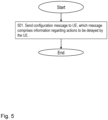
- Figure 5 discloses a flowchart depicting embodiments of a method performed by the network node 110, for handling DRX operation.
- the network node 110 may send a configuration message to the UE 120.
- the configuration message may comprise information regarding actions to be delayed by the UE 120.
- the message may comprise information about which action or which actions to apply the delay to, the amount of time the action(s) should be delayed and/or conditions for when the delays should be applied.
- the action may be a decoding of a received signal
- the information may e.g. comprise a decoding delay to be applied to signals received by the UE 120 during a predetermined first time period from the entering of an active state.
- the active state may be a semi-awake state in which the UE listens for a specific signal which may be received using only a part of a radio unit.
- the specific signal may e.g. be a signal which is easy to decode.
- Whether the UE 120 applies the behaviors according to the embodiments A to D described herein, such as e.g. slow decoding, delayed timer start, etc., or not may be configured by the network, e.g. by means of the network node 110. This may e.g. be configured using RRC signaling.
- the network may determine whether to configure the behaviors described herein for the UE 120 based on which traffic the UE 120 has active, which types of bearers the UE 120 has active, the need for power savings for the UE 120, etc.
- the network may configure that the UE 120 should not apply slow decoding. This configuration may be performed by sending the configuration message as described in Action 501.
- the UE 120 may apply different behaviors depending on which type of DRX-cycle the UE 120 is applying. For example, if the UE 120 is applying a long DRX-cycle, the UE 120 may apply behaviors which the UE 120 does not apply when applying a short DRX-cycle. This is beneficial since long DRX is in general a state where more power should be saved since this is the state when the UE 120 does not get frequent data transmissions and hence delay may be acceptable. Hence, the UE 120 may apply features described above to reduce the power consumption. It may further be specified in a specification that one or more of the behaviors described above is applied when the UE 120 applies a certain type of DRX-cycle. According to another embodiment, the network may configure, depending on the type of DRX-cycle, which behavior(s) the UE 120 shall apply.
- the delay for communicating a packet may be increased which may negatively impact user experience and system efficiency.
- a DRX configuration may therefore be adjusted to reduce the delay. This may e.g. be done to compensate for the potential longer delay.
- a network node 110 such as e.g. an eNB, configuring a DRX configuration for the UE 120 which makes the UE 120 wake up earlier if it applies the embodiments described herein.
- the eNB may configure the UE 120 to apply a shorter DRX periodicity. This would then make the UE 120 wake up more frequently.
- T WU time in time in which the "wake up" message was received.
- the network node 110 such as the eNB, may configure the UE B to wake up earlier and/or more frequently, in order to compensate for this additional delay. This configuration may also be performed by sending the configuration message as described in Action 501.
- the UE 120 may indicate to the network if it supports one or more of the behaviors described herein.
- the network node 110 such as an eNB, may then consider this when determining whether to configure these behaviors for the UE 120.
- Fig. 6 is a block diagram depicting the UE 120 for performing the method for handling DRX operation.
- the UE 120 may comprise a processor 601, such as e.g. a processing circuitry, configured to perform the method as described herein, as performed by the UE 120. Dashed lines of a box in Figure 6 indicate that this box is not mandatory and relate to some embodiments only.
- the UE 120 is configured to apply a delay for at least one action performed as a response to data and/or signaling received by the UE 120 during a predefined first time period after the UE 120 has entered an active state.
- the UE 120 may further be configured to apply a first decoding (D1) delay for signals received by the UE 120 during a predetermined first time period from the entering of the active state when the action is a decoding of a received signal.
- the first decoding delay (D1) is a longer decoding delay and the second decoding delay (D2) is a shorter decoding delay.
- the first decoding delay (D1) is an increased decoding delay in comparison to a second decoding delay (D2).
- the UE 120 may further be configured to reduce or to remove the coding delay when the time from entering the active state has exceeded the predetermined first time limit.
- the UE 120 may further be configured to apply the increased decoding delay only for data received during the active state.
- the UE 120 may further be configured to delay the transmission of HARQ feedback for Downlink (DL) and/or UpLink (UL) data during a predetermined second time period after the UE 120 has entered the active state.
- DL Downlink
- UL UpLink
- the UE 120 may further be configured to omit to send a HARQ feedback for DownLink, DL, and/or UpLink, UL data during the predetermined second time period after the UE 120 has entered the active state.
- the UE 120 may further be configured to apply a delayed starting of the timer, such as the inactivity timer, during a predetermined third time period after the UE 120 has entered the active state.
- a delayed starting of the timer such as the inactivity timer
- the UE 120 may further be configured to apply an adjusted duration of the timer, such as the inactivity timer, when a delayed starting of the timer has been applied.
- an adjusted duration of the timer such as the inactivity timer
- the UE 120 may further be configured to receive an indication from the network node 110, indicating that the UE 120 shall enter an awake state when it has been sleeping, and wherein the UE 120 may further be configured to apply a delay to the entering of the awake DRX state when the UE 120 has received an indication from the network node 110 that the UE 120 shall enter the awake state.
- the UE 120 may further be configured to receive a message from a network node 110, which message comprises information regarding the actions to be delayed, and wherein the UE 120 may further be configured to apply the delay according to the information comprised in the message.
- the UE 120 may further comprise a memory 602.
- the memory 602 may comprise one or more units to be used to store data on, such as system information, applications to perform the methods disclosed herein when being executed, and similar.
- the methods according to the embodiments described herein for the UE 120 may respectively be implemented by means of e.g. a computer program 603 or a computer program product, comprising instructions, i.e., software code portions, which, when executed on at least one processor, cause the at least one processor to carry out the actions described herein, as performed by the determining module.
- the computer program 603 may be stored on a computer-readable storage medium 604, e.g. a disc or similar.
- the computer-readable storage medium 604, having stored thereon the computer program may comprise the instructions which, when executed on at least one processor, cause the at least one processor to carry out the actions described herein, as performed by the UE 120.
- the computer-readable storage medium may be a non-transitory computer-readable storage medium.
- the embodiments herein may be implemented through one or more processors, such as the processor in the UE 120 depicted in Figure 6 , and/or a processor in a network node together with computer program code for performing the functions and actions of the embodiments herein.
- the program code mentioned above may also be provided as a computer program product, for instance in the form of a data carrier carrying computer program code for performing the embodiments herein when being loaded into the UE and/or the network node.
- One such carrier may be in the form of a CD ROM disc. It is however feasible with other data carriers such as a memory stick.
- the computer program code may furthermore be provided as pure program code on a server and downloaded to the UE and/or the network node.
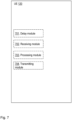
- the UE 120 may comprise a delay module 701, a receiving module 702, a processing module 703 and/or a transmitting module 704 configured for performing the method described herein, as performed by the UE 120.
- the UE 120 may comprise the delay module 701 being configured to apply a delay for at least one action performed as a response to data and/or signaling received by the UE 120 during a predefined first time period after the UE 120 has entered an active state.
- the UE 120 may comprise the delay module 701 further being configured to apply a first decoding (D1) delay for signals received by the UE 120 during a predetermined first time period from the entering of the active state when the action is a decoding of a received signal.
- the delay module 701 may further being configured to, reduce or to remove the coding delay when the time from entering the active state has exceeded the predetermined first time limit.
- the delay module 701 may further being configured to apply the increased decoding delay only for data received during the active state.
- the UE 120 may comprise the delay module 701 or the transmitting module 704 being configured to delay the transmission of HARQ feedback for DownLink (DL) and/or UpLink (UL) data during a predetermined second time period after the UE 120 has entered the active state.
- DL DownLink
- UL UpLink
- the delay module 701 may further be configured to omit to send a HARQ feedback for DownLink, DL, and/or UpLink, UL data during the predetermined second time period after the UE 120 has entered the active state.
- the delay module 701 may further be configured to apply a delayed starting of the timer, such as the inactivity timer, during a predetermined third time period after the UE 120 has entered the active state.
- the delay module 701 may further be configured to apply an adjusted duration of the timer, such as the inactivity timer, when a delayed starting of the timer has been applied.
- the UE 120 may comprise the receiving module 702 being configured to receive an indication from the network node 110 indicating that the UE 120 shall enter an awake state when it has been sleeping.
- the UE 120 may further comprise a processing module 703 or the delay module 701 further being configured to apply a delay to the entering of the awake DRX state when the receiving module has received an indication from the network node 110 that the UE 120 shall enter the awake state.
- the receiving module 702 may further be configured to, receive a message from a network node 110, which message comprises information regarding the actions to be delayed.
- the delay module 701 may further be configured to, apply the delay according to the information comprised in the message.
- processors or “controller” as used herein does not exclusively refer to hardware capable of executing software and may implicitly include, without limitation, digital signal processor (DSP) hardware, read-only memory (ROM) for storing software, random-access memory for storing software and/or program or application data, and nonvolatile memory.
- DSP digital signal processor
- ROM read-only memory
- RAM random-access memory
- nonvolatile memory nonvolatile memory
- Fig. 8 is a block diagram depicting the network node 110 for performing the method for handling DRX operation.
- the network node 110 may comprise a processor801, such as e.g. a processing circuitry, configured to perform the method as described herein, as performed by the network node 110. Dashed lines of a box in Figure 8 indicate that this box is not mandatory and relate to some embodiments only.
- the network node 110 is configured to send a configuration message to the UE 120, which message comprises information regarding actions to be delayed by the UE 120.
- the network node 110 may be configured to send a configuration message to the UE 120, which message comprises information regarding actions to be delayed by the UE 120.
- the network node 110 may further comprise a memory 802.
- the memory 802 may comprise one or more units to be used to store data on, such as system information, applications to perform the methods disclosed herein when being executed, and similar.
- the methods according to the embodiments described herein for the network node 110 may respectively be implemented by means of e.g. a computer program 803 or a computer program product, comprising instructions, i.e., software code portions, which, when executed on at least one processor, cause the at least one processor to carry out the actions described herein, as performed by the network node.
- the computer program 803 may be stored on a computer-readable storage medium 804 e.g. a disc or similar.
- the computer-readable storage medium 805 having stored thereon the computer program may comprise instructions which, when executed on at least one processor, cause the at least one processor to carry out the actions described herein, as performed by the network node.
- the computer-readable storage medium may be a non-transitory computer-readable storage medium.
- processors or “controller” as used herein does not exclusively refer to hardware capable of executing software and may implicitly include, without limitation, digital signal processor (DSP) hardware, read-only memory (ROM) for storing software, random-access memory for storing software and/or program or application data, and nonvolatile memory.
- DSP digital signal processor
- ROM read-only memory
- RAM random-access memory
- nonvolatile memory nonvolatile memory
- the embodiments herein may be implemented through one or more processors, such as the processor network node 110 depicted in Figure 8 together with computer program code for performing the functions and actions of the embodiments herein.
- the program code mentioned above may also be provided as a computer program product, for instance in the form of a data carrier carrying computer program code for performing the embodiments herein when being loaded into the UE and/or the network node.
- a data carrier carrying computer program code for performing the embodiments herein when being loaded into the UE and/or the network node.
- One such carrier may be in the form of a CD ROM disc. It is however feasible with other data carriers such as a memory stick.
- the computer program code may furthermore be provided as pure program code on a server and downloaded to the UE and/or the network node.
- the network node 110 may comprise a sending module 902 being configured to send a configuration message to the UE 120, which message comprises information regarding actions to be delayed by the UE 120.
- the methods according to the embodiments described herein performed by the UE 120 and/or the network node 110 may be implemented by means of a computer program product, comprising instructions, i.e. software code portions, which, when executed on at least one processor, cause the at least one processor to carry out the actions described herein, as performed by the UE 120 and/or the network node 110.
- the computer program product may be stored on a computer-readable storage medium.
- the computer-readable storage medium, having stored there on the computer program may comprise the instructions which, when executed on at least one processor, cause the at least one processor to carry out the actions described herein, as performed by the UE 120 and/or the network node 110.
- the computer-readable storage medium may be a non-transitory computer-readable storage medium.
- the UE 120 and/or the network node 110 may further each comprise a memory comprising one or more memory units.
- the memory is arranged to be used to store obtained information such as indications of a mobility set, identifiers of APs and WLANs, identifiers of UEs, ciphering keys, measurements of signals from radio access nodes, measurement reports or parts thereof and applications etc. to perform the methods herein when being executed in the UE and/or the network node.
- a computer program comprises instructions, which when executed by the at least one processor such as the processor 601 and/or 801, cause the at least one processor 601 and/or 801 to perform actions according to any of the above Actions.
- a carrier comprises the computer program, wherein the carrier is one of an electronic signal, an optical signal, an electromagnetic signal, a magnetic signal, an electric signal, a radio signal, a microwave signal, or a computer-readable storage medium.
Landscapes
- Engineering & Computer Science (AREA)
- Computer Networks & Wireless Communication (AREA)
- Signal Processing (AREA)
- Mobile Radio Communication Systems (AREA)
Claims (14)
- Verfahren, das durch ein Benutzergerät (User Equipment - UE) durchgeführt wird, zum Handhaben eines unkontinuierlichen Empfangs(DRX)-Vorgangs, wobei das Verfahren Folgendes umfasst:
Empfangen einer Aufwecknachricht von einem Netzwerkknoten, während sich das UE in einem Ruhezustand befindet, wobei die Aufwecknachricht angibt, dass das UE den Ruhezustand verlassen und innerhalb einer gewissen Zeitspanne nach dem Empfangen oder Dekodieren der Aufwecknachricht in einen Wachzustand eintreten muss, wodurch eine Zeitverzögerung (TWU) von dem Zeitpunkt, an dem das UE die Aufwecknachricht empfängt, bis zu dem tatsächlichen Aufwachen des UE eingeführt wird. - Verfahren nach Anspruch 1, wobei die Aufwecknachricht in einem Downlink-Steuerindikator (downlink control indicator - DCI) eines physischen Steuerkanals angegeben wird, sodass zum Überwachen der Aufwecknachricht:das UE nur physische Steuerkanäle überwachen muss, die eine Uplink-Planung angeben, und Downlink-Datenkanäle von der Überwachung und Dekodierung ausschließen muss, während sich das UE in dem DRX-Ruhezustand befindet, oderdas UE nur die physischen Steuerkanäle überwachen muss, die die Uplink-Planung während einer onDuration eines DRX-Zyklus angeben.
- Verfahren nach Anspruch 1, wobei das Verfahren ferner Folgendes umfasst:
Empfangen, von dem Netzwerkknoten, einer Konfiguration, die angibt, wann das UE das Empfangen der Aufwecknachricht erwarten sollte. - Verfahren nach Anspruch 3, Wobei die Konfiguration einen Versatz umfasst, der angibt, wann in Bezug auf eine Referenz Überwachungslaufzeiten beginnen sollen.
- Verfahren, das durch einen Netzwerkknoten durchgeführt wird, zum Handhaben eines unkontinuierlichen Empfangs(DRX)-Vorgangs, wobei das Verfahren Folgendes umfasst:Senden einer Aufwecknachricht an ein Benutzergerät (UE), während sich das UE in einem Ruhezustand befindet,wobei die Aufwecknachricht angibt, dass das UE den Ruhezustand verlassen und innerhalb einer gewissen Zeitspanne nach dem Empfangen oder Dekodieren der Aufwecknachricht in einen Wachzustand eintreten muss, wodurch eine Zeitverzögerung (TWU) von dem Zeitpunkt, an dem das UE die Aufwecknachricht empfängt, bis zu dem tatsächlichen Aufwachen des UE eingeführt wird.
- Verfahren nach Anspruch 5, wobei die Aufwecknachricht in einem Downlink-Steuerindikator (DCI) eines physischen Steuerkanals angegeben wird, sodass zum Überwachen der Aufwecknachricht:das UE nur physische Steuerkanäle überwachen muss, die eine Uplink-Planung angeben, und Downlink-Datenkanäle von der Überwachung und Dekodierung ausschließen muss, während sich das UE in dem Ruhezustand befindet, oderdas UE nur die physischen Steuerkanäle überwachen muss, die die Uplink-Planung während einer onDuration eines DRX-Zyklus angeben.
- Verfahren nach Anspruch 5, wobei das Verfahren ferner Folgendes umfasst:
Senden, an das UE, einer Konfiguration, die angibt, wann das UE das Empfangen der Aufwecknachricht erwarten sollte. - Verfahren nach Anspruch 7, wobei die Konfiguration einen Versatz umfasst, der angibt, wann in Bezug auf eine Referenz Überwachungslaufzeiten beginnen sollen.
- Benutzergerät (UE) zum Handhaben eines unkontinuierlichen Empfangs(DRX)-Vorgangs, umfassend einen Prozessor und einen Speicher, wobei der Speicher Anweisungen enthält, die durch den Prozessor ausführbar sind, wobei das UE zu Folgendem konfiguriert ist:
Empfangen einer Aufwecknachricht von einem Netzwerkknoten, während sich das UE in einem Ruhezustand befindet, wobei die Aufwecknachricht angibt, dass das UE den Ruhezustand verlassen und innerhalb einer gewissen Zeitspanne nach dem Empfangen oder Dekodieren der Aufwecknachricht in einen Wachzustand eintreten muss, wodurch eine Zeitverzögerung (TWU) von dem Zeitpunkt, an dem das UE die Aufwecknachricht empfängt, bis zu dem tatsächlichen Aufwachen des UE eingeführt wird. - UE nach Anspruch 9, wobei das UE konfiguriert ist, um das Verfahren nach einem der Ansprüche 2-4 durchzuführen.
- Netzwerkknoten zum Handhaben eines unkontinuierlichen Empfangs(DRX)-Vorgangs, umfassend einen Prozessor und einen Speicher, wobei der Speicher Anweisungen enthält, die durch den Prozessor ausführbar sind, wobei der Netzwerkknoten konfiguriert ist zum:Senden einer Aufwecknachricht an ein Benutzergerät (UE), während sich das UE in einem Ruhezustand befindet,wobei die Aufwecknachricht angibt, dass das UE den Ruhezustand verlassen und innerhalb einer gewissen Zeitspanne nach dem Empfangen oder Dekodieren der Aufwecknachricht in einen Wachzustand eintreten muss, wodurch eine Zeitverzögerung (TWU) von dem Zeitpunkt, an dem das UE die Aufwecknachricht empfängt, bis zu dem tatsächlichen Aufwachen des UE eingeführt wird.
- Netzwerkknoten nach Anspruch 11, wobei der Netzwerkknoten konfiguriert ist, um das Verfahren nach einem der Ansprüche 6-8 durchzuführen.
- Computerprogramm, umfassend Anweisungen, die, wenn sie auf mindestens einem Prozessor ausgeführt werden, den mindestens einen Prozessor veranlassen, das Verfahren nach einem der Ansprüche 1-8 auszuüben, wie es durch das UE bzw. den Netzwerkknoten ausgeführt wird.
- Computerlesbares Speichermedium, auf dem das Computerprogramm nach Anspruch 13 gespeichert ist.
Priority Applications (1)
| Application Number | Priority Date | Filing Date | Title |
|---|---|---|---|
| EP25154289.0A EP4561193A3 (de) | 2016-08-19 | 2017-08-18 | Verfahren und vorrichtung zum handhaben von unkontinuierlichem empfang in einem kommunikationsnetz |
Applications Claiming Priority (3)
| Application Number | Priority Date | Filing Date | Title |
|---|---|---|---|
| US201662376985P | 2016-08-19 | 2016-08-19 | |
| EP17761934.3A EP3501129B1 (de) | 2016-08-19 | 2017-08-18 | Verfahren und vorrichtung zur handhabung eines diskontinuierlichen empfangs in einem kommunikationsnetz |
| PCT/SE2017/050831 WO2018034611A1 (en) | 2016-08-19 | 2017-08-18 | Method and apparatus for handling discontinuous reception in a communications network |
Related Parent Applications (1)
| Application Number | Title | Priority Date | Filing Date |
|---|---|---|---|
| EP17761934.3A Division EP3501129B1 (de) | 2016-08-19 | 2017-08-18 | Verfahren und vorrichtung zur handhabung eines diskontinuierlichen empfangs in einem kommunikationsnetz |
Related Child Applications (2)
| Application Number | Title | Priority Date | Filing Date |
|---|---|---|---|
| EP25154289.0A Division EP4561193A3 (de) | 2016-08-19 | 2017-08-18 | Verfahren und vorrichtung zum handhaben von unkontinuierlichem empfang in einem kommunikationsnetz |
| EP25154289.0A Division-Into EP4561193A3 (de) | 2016-08-19 | 2017-08-18 | Verfahren und vorrichtung zum handhaben von unkontinuierlichem empfang in einem kommunikationsnetz |
Publications (3)
| Publication Number | Publication Date |
|---|---|
| EP4064597A1 EP4064597A1 (de) | 2022-09-28 |
| EP4064597C0 EP4064597C0 (de) | 2025-03-05 |
| EP4064597B1 true EP4064597B1 (de) | 2025-03-05 |
Family
ID=59791110
Family Applications (3)
| Application Number | Title | Priority Date | Filing Date |
|---|---|---|---|
| EP25154289.0A Pending EP4561193A3 (de) | 2016-08-19 | 2017-08-18 | Verfahren und vorrichtung zum handhaben von unkontinuierlichem empfang in einem kommunikationsnetz |
| EP22166787.6A Active EP4064597B1 (de) | 2016-08-19 | 2017-08-18 | Verfahren und vorrichtung zum handhaben von unkontinuierlichem empfang in einem kommunikationsnetz |
| EP17761934.3A Active EP3501129B1 (de) | 2016-08-19 | 2017-08-18 | Verfahren und vorrichtung zur handhabung eines diskontinuierlichen empfangs in einem kommunikationsnetz |
Family Applications Before (1)
| Application Number | Title | Priority Date | Filing Date |
|---|---|---|---|
| EP25154289.0A Pending EP4561193A3 (de) | 2016-08-19 | 2017-08-18 | Verfahren und vorrichtung zum handhaben von unkontinuierlichem empfang in einem kommunikationsnetz |
Family Applications After (1)
| Application Number | Title | Priority Date | Filing Date |
|---|---|---|---|
| EP17761934.3A Active EP3501129B1 (de) | 2016-08-19 | 2017-08-18 | Verfahren und vorrichtung zur handhabung eines diskontinuierlichen empfangs in einem kommunikationsnetz |
Country Status (4)
| Country | Link |
|---|---|
| US (3) | US11284469B2 (de) |
| EP (3) | EP4561193A3 (de) |
| CN (2) | CN109565380B (de) |
| WO (1) | WO2018034611A1 (de) |
Families Citing this family (12)
| Publication number | Priority date | Publication date | Assignee | Title |
|---|---|---|---|---|
| US12192899B2 (en) * | 2017-08-18 | 2025-01-07 | Qualcomm Incorporated | Transmission of wakeup signal through millimeter wave and sub-6 GHz bands |
| CN110086585B (zh) * | 2018-03-21 | 2020-07-21 | 中国信息通信研究院 | 一种上行控制信息传输方法及设备 |
| CN109219116B (zh) * | 2018-08-09 | 2022-05-31 | 华为技术有限公司 | 一种终端设备的休眠方法及装置 |
| WO2020038402A1 (zh) * | 2018-08-22 | 2020-02-27 | 华为技术有限公司 | 传输控制方法和装置 |
| US11425659B2 (en) * | 2019-01-15 | 2022-08-23 | Qualcomm Incorporated | Periodic reception mode for wireless communications |
| BR112022001698A2 (pt) | 2019-07-31 | 2022-03-22 | Zte Corp | Configuração de recepção descontínua (drx) para relação automática de vizinhança (anr) |
| CN117082605A (zh) * | 2019-11-07 | 2023-11-17 | 苹果公司 | 非连续接收周期期间的唤醒信令 |
| EP4059307A4 (de) * | 2019-11-15 | 2023-11-01 | Qualcomm Incorporated | Techniken für ein steuerkanalaufwecksignal |
| CN115516795B (zh) * | 2020-05-15 | 2025-08-01 | Oppo广东移动通信有限公司 | 一种信息处理方法、终端设备及存储介质 |
| CN114501689B (zh) * | 2020-10-23 | 2025-06-10 | 大唐移动通信设备有限公司 | 直接通信接口的drx控制方法、装置、终端及存储介质 |
| US20240064854A1 (en) * | 2022-08-17 | 2024-02-22 | Qualcomm Incorporated | Beam specific idle discontinuous reception configuration |
| WO2024098225A1 (en) * | 2022-11-07 | 2024-05-16 | Nokia Shanghai Bell Co., Ltd. | Lower power wake-up signal operation with discontinuous reception configuration |
Family Cites Families (17)
| Publication number | Priority date | Publication date | Assignee | Title |
|---|---|---|---|---|
| KR20050029254A (ko) * | 2003-09-20 | 2005-03-24 | 삼성전자주식회사 | 광대역 무선 통신시스템의 슬리핑 스테이트에서 모드간의상태 천이를 위한 웨이크업 채널 전송 장치 및 방법 |
| US8818321B2 (en) | 2006-06-20 | 2014-08-26 | Nokia Corporation | Method and system for providing reply-controlled discontinuous reception |
| US8072963B2 (en) * | 2007-02-14 | 2011-12-06 | Research In Motion Limited | Method and system for recovering from DRX timing de-synchronization in LTE—ACTIVE |
| CN101355573B (zh) | 2007-07-27 | 2011-09-07 | 中国移动通信集团公司 | 提高无线数据业务接入速度的方法 |
| JP5291186B2 (ja) * | 2008-04-25 | 2013-09-18 | インターデイジタル パテント ホールディングス インコーポレイテッド | Dc−hsdpaにおいて2つの搬送波上同時に受信してdtxおよびdrxを実行するための方法および装置 |
| WO2010044721A1 (en) * | 2008-10-17 | 2010-04-22 | Telefonaktiebolaget L M Ericsson (Publ) | Method for improving battery life and harq retransmissions in wireless communications systems |
| KR20120069855A (ko) * | 2010-12-21 | 2012-06-29 | 삼성전자주식회사 | 무선통신시스템에서 핸드오버를 위한 시스템 및 방법 |
| WO2012149321A1 (en) * | 2011-04-29 | 2012-11-01 | Research In Motion Limited | Switching activation of ue receivers |
| CN103139920B (zh) * | 2011-11-24 | 2016-06-29 | 华为技术有限公司 | 一种用于非连续接收配置的方法和用户设备 |
| JP6046236B2 (ja) * | 2012-04-05 | 2016-12-14 | オプティス セルラー テクノロジー, エルエルシーOptis Cellular Technology, LLC | ページングコンフィグレーション情報の受信用の促進ウェイクアップ |
| US9585091B2 (en) * | 2012-08-17 | 2017-02-28 | Qualcomm Incorporated | Systems and methods for low power wake up signal and operations for WLAN |
| CA2912255C (en) * | 2013-05-10 | 2018-11-20 | Telefonaktiebolaget L M Ericsson (Publ) | Methods and apparatuses for signaling in dynamic time division duplex systems |
| US9842733B2 (en) * | 2013-06-11 | 2017-12-12 | Imec Vzw | Method for dissolving chalcogen elements and metal chalcogenides in non-hazardous solvents |
| EP3008967B1 (de) | 2013-06-13 | 2019-04-24 | Sony Corporation | Telekommunikationsvorrichtung und verfahren |
| EP3008968B1 (de) * | 2013-06-13 | 2019-04-24 | Sony Corporation | Telekommunikationsvorrichtung und verfahren |
| WO2016146147A1 (en) * | 2015-03-13 | 2016-09-22 | Huawei Technologies Co., Ltd. | Apparatus and methods in a wireless communication network for discontinuous reception and data reception |
| US10602567B2 (en) * | 2016-08-12 | 2020-03-24 | Motorola Mobility Llc | Methods, devices, and systems for discontinuous reception for a shortened transmission time interval and processing time |
-
2017
- 2017-08-18 EP EP25154289.0A patent/EP4561193A3/de active Pending
- 2017-08-18 CN CN201780050450.3A patent/CN109565380B/zh not_active Expired - Fee Related
- 2017-08-18 US US16/323,313 patent/US11284469B2/en active Active
- 2017-08-18 EP EP22166787.6A patent/EP4064597B1/de active Active
- 2017-08-18 WO PCT/SE2017/050831 patent/WO2018034611A1/en not_active Ceased
- 2017-08-18 CN CN202210781554.4A patent/CN115174012B/zh active Active
- 2017-08-18 EP EP17761934.3A patent/EP3501129B1/de active Active
-
2022
- 2022-03-21 US US17/699,307 patent/US12356495B2/en active Active
-
2025
- 2025-07-07 US US19/260,938 patent/US20250338349A1/en active Pending
Also Published As
| Publication number | Publication date |
|---|---|
| WO2018034611A1 (en) | 2018-02-22 |
| EP3501129A1 (de) | 2019-06-26 |
| CN115174012A (zh) | 2022-10-11 |
| US12356495B2 (en) | 2025-07-08 |
| EP4064597C0 (de) | 2025-03-05 |
| US11284469B2 (en) | 2022-03-22 |
| US20220210867A1 (en) | 2022-06-30 |
| US20210289582A1 (en) | 2021-09-16 |
| CN109565380A (zh) | 2019-04-02 |
| EP4064597A1 (de) | 2022-09-28 |
| US20250338349A1 (en) | 2025-10-30 |
| CN115174012B (zh) | 2024-04-16 |
| EP4561193A3 (de) | 2025-08-06 |
| EP3501129B1 (de) | 2022-04-06 |
| CN109565380B (zh) | 2022-07-01 |
| EP4561193A2 (de) | 2025-05-28 |
Similar Documents
| Publication | Publication Date | Title |
|---|---|---|
| US12356495B2 (en) | Method and apparatus for handling discontinuous reception in a communications network | |
| EP3927023B1 (de) | Verfahren und vorrichtung zur verwendung eines leistungssparenden signalisierungsmodus und endgerät | |
| EP4007376B1 (de) | Verfahren und vorrichtung zur leistungsbewahrung, endgerät, zugangsnetzwerkgerät und lesbares speichermedium | |
| US10952142B2 (en) | Energy-efficient paging in wireless networks | |
| EP4132209A1 (de) | Drx-steuerungsverfahren und -vorrichtung | |
| CN110913462B (zh) | 信道的监听、节能信号的处理、装置、终端及网络侧设备 | |
| US9414313B2 (en) | Discontinuous reception (DRX) for diverse traffic | |
| CN111165035A (zh) | 与无线通信网络中的寻呼相关的方法和设备 | |
| CN111527773A (zh) | 用户终端的省电方法、装置、通信设备及存储介质 | |
| CN114271021A (zh) | 用于确定非连续接收持续定时器的启动状态的方法及设备 | |
| US10512102B2 (en) | Method and apparatus for triggering an active time to monitor for discontinuous reception | |
| US12395929B2 (en) | Reception scheme | |
| EP3952473A1 (de) | Verfahren und vorrichtung für diskontinuierlichen empfang | |
| CN118355696A (zh) | 节电方法和无线通信系统 | |
| CN114846855A (zh) | 通信方法、设备和计算机可读介质 | |
| CN114287168B (zh) | 电信系统中的下行链路监测 | |
| HK40115882A (en) | Method and apparatus for triggering an active time to monitor for discontinuous reception | |
| CN120153715A (zh) | 具有非连续接收配置的较低功率唤醒信号操作 |
Legal Events
| Date | Code | Title | Description |
|---|---|---|---|
| PUAI | Public reference made under article 153(3) epc to a published international application that has entered the european phase |
Free format text: ORIGINAL CODE: 0009012 |
|
| STAA | Information on the status of an ep patent application or granted ep patent |
Free format text: STATUS: REQUEST FOR EXAMINATION WAS MADE |
|
| 17P | Request for examination filed |
Effective date: 20220405 |
|
| AC | Divisional application: reference to earlier application |
Ref document number: 3501129 Country of ref document: EP Kind code of ref document: P |
|
| AK | Designated contracting states |
Kind code of ref document: A1 Designated state(s): AL AT BE BG CH CY CZ DE DK EE ES FI FR GB GR HR HU IE IS IT LI LT LU LV MC MK MT NL NO PL PT RO RS SE SI SK SM TR |
|
| REG | Reference to a national code |
Ref legal event code: R079 Free format text: PREVIOUS MAIN CLASS: H04L0001180000 Ref country code: DE Ref document number: 602017088248 Country of ref document: DE Ipc: H04L0001182900 |
|
| GRAP | Despatch of communication of intention to grant a patent |
Free format text: ORIGINAL CODE: EPIDOSNIGR1 |
|
| STAA | Information on the status of an ep patent application or granted ep patent |
Free format text: STATUS: GRANT OF PATENT IS INTENDED |
|
| RIC1 | Information provided on ipc code assigned before grant |
Ipc: H04W 52/02 20090101ALI20240919BHEP Ipc: H04L 1/1829 20230101AFI20240919BHEP |
|
| INTG | Intention to grant announced |
Effective date: 20240930 |
|
| GRAS | Grant fee paid |
Free format text: ORIGINAL CODE: EPIDOSNIGR3 |
|
| GRAA | (expected) grant |
Free format text: ORIGINAL CODE: 0009210 |
|
| STAA | Information on the status of an ep patent application or granted ep patent |
Free format text: STATUS: THE PATENT HAS BEEN GRANTED |
|
| AC | Divisional application: reference to earlier application |
Ref document number: 3501129 Country of ref document: EP Kind code of ref document: P |
|
| AK | Designated contracting states |
Kind code of ref document: B1 Designated state(s): AL AT BE BG CH CY CZ DE DK EE ES FI FR GB GR HR HU IE IS IT LI LT LU LV MC MK MT NL NO PL PT RO RS SE SI SK SM TR |
|
| REG | Reference to a national code |
Ref country code: GB Ref legal event code: FG4D |
|
| REG | Reference to a national code |
Ref country code: CH Ref legal event code: EP |
|
| REG | Reference to a national code |
Ref country code: IE Ref legal event code: FG4D |
|
| REG | Reference to a national code |
Ref country code: DE Ref legal event code: R096 Ref document number: 602017088248 Country of ref document: DE |
|
| U01 | Request for unitary effect filed |
Effective date: 20250305 |
|
| U07 | Unitary effect registered |
Designated state(s): AT BE BG DE DK EE FI FR IT LT LU LV MT NL PT RO SE SI Effective date: 20250311 |
|
| PG25 | Lapsed in a contracting state [announced via postgrant information from national office to epo] |
Ref country code: RS Free format text: LAPSE BECAUSE OF FAILURE TO SUBMIT A TRANSLATION OF THE DESCRIPTION OR TO PAY THE FEE WITHIN THE PRESCRIBED TIME-LIMIT Effective date: 20250605 |
|
| PG25 | Lapsed in a contracting state [announced via postgrant information from national office to epo] |
Ref country code: ES Free format text: LAPSE BECAUSE OF FAILURE TO SUBMIT A TRANSLATION OF THE DESCRIPTION OR TO PAY THE FEE WITHIN THE PRESCRIBED TIME-LIMIT Effective date: 20250305 |
|
| PG25 | Lapsed in a contracting state [announced via postgrant information from national office to epo] |
Ref country code: NO Free format text: LAPSE BECAUSE OF FAILURE TO SUBMIT A TRANSLATION OF THE DESCRIPTION OR TO PAY THE FEE WITHIN THE PRESCRIBED TIME-LIMIT Effective date: 20250605 |
|
| PG25 | Lapsed in a contracting state [announced via postgrant information from national office to epo] |
Ref country code: HR Free format text: LAPSE BECAUSE OF FAILURE TO SUBMIT A TRANSLATION OF THE DESCRIPTION OR TO PAY THE FEE WITHIN THE PRESCRIBED TIME-LIMIT Effective date: 20250305 |
|
| PG25 | Lapsed in a contracting state [announced via postgrant information from national office to epo] |
Ref country code: GR Free format text: LAPSE BECAUSE OF FAILURE TO SUBMIT A TRANSLATION OF THE DESCRIPTION OR TO PAY THE FEE WITHIN THE PRESCRIBED TIME-LIMIT Effective date: 20250606 |
|
| U20 | Renewal fee for the european patent with unitary effect paid |
Year of fee payment: 9 Effective date: 20250827 |
|
| PG25 | Lapsed in a contracting state [announced via postgrant information from national office to epo] |
Ref country code: SM Free format text: LAPSE BECAUSE OF FAILURE TO SUBMIT A TRANSLATION OF THE DESCRIPTION OR TO PAY THE FEE WITHIN THE PRESCRIBED TIME-LIMIT Effective date: 20250305 |
|
| PG25 | Lapsed in a contracting state [announced via postgrant information from national office to epo] |
Ref country code: PL Free format text: LAPSE BECAUSE OF FAILURE TO SUBMIT A TRANSLATION OF THE DESCRIPTION OR TO PAY THE FEE WITHIN THE PRESCRIBED TIME-LIMIT Effective date: 20250305 |
|
| PGFP | Annual fee paid to national office [announced via postgrant information from national office to epo] |
Ref country code: GB Payment date: 20250827 Year of fee payment: 9 |
|
| PG25 | Lapsed in a contracting state [announced via postgrant information from national office to epo] |
Ref country code: CZ Free format text: LAPSE BECAUSE OF FAILURE TO SUBMIT A TRANSLATION OF THE DESCRIPTION OR TO PAY THE FEE WITHIN THE PRESCRIBED TIME-LIMIT Effective date: 20250305 |
|
| PG25 | Lapsed in a contracting state [announced via postgrant information from national office to epo] |
Ref country code: SK Free format text: LAPSE BECAUSE OF FAILURE TO SUBMIT A TRANSLATION OF THE DESCRIPTION OR TO PAY THE FEE WITHIN THE PRESCRIBED TIME-LIMIT Effective date: 20250305 |
|
| PG25 | Lapsed in a contracting state [announced via postgrant information from national office to epo] |
Ref country code: IS Free format text: LAPSE BECAUSE OF FAILURE TO SUBMIT A TRANSLATION OF THE DESCRIPTION OR TO PAY THE FEE WITHIN THE PRESCRIBED TIME-LIMIT Effective date: 20250705 |