EP4064508A1 - Verfahren und vorrichtung zur wärmeableitungssteuerung einer ladestation und endgerätevorrichtung - Google Patents
Verfahren und vorrichtung zur wärmeableitungssteuerung einer ladestation und endgerätevorrichtung Download PDFInfo
- Publication number
- EP4064508A1 EP4064508A1 EP21194062.2A EP21194062A EP4064508A1 EP 4064508 A1 EP4064508 A1 EP 4064508A1 EP 21194062 A EP21194062 A EP 21194062A EP 4064508 A1 EP4064508 A1 EP 4064508A1
- Authority
- EP
- European Patent Office
- Prior art keywords
- charging base
- control instruction
- terminal device
- control
- heat dissipation
- Prior art date
- Legal status (The legal status is an assumption and is not a legal conclusion. Google has not performed a legal analysis and makes no representation as to the accuracy of the status listed.)
- Granted
Links
Images




Classifications
-
- G—PHYSICS
- G05—CONTROLLING; REGULATING
- G05B—CONTROL OR REGULATING SYSTEMS IN GENERAL; FUNCTIONAL ELEMENTS OF SUCH SYSTEMS; MONITORING OR TESTING ARRANGEMENTS FOR SUCH SYSTEMS OR ELEMENTS
- G05B15/00—Systems controlled by a computer
- G05B15/02—Systems controlled by a computer electric
-
- H—ELECTRICITY
- H02—GENERATION; CONVERSION OR DISTRIBUTION OF ELECTRIC POWER
- H02J—ELECTRIC POWER NETWORKS; CIRCUIT ARRANGEMENTS OR SYSTEMS FOR SUPPLYING OR DISTRIBUTING ELECTRIC POWER; SYSTEMS FOR STORING ELECTRIC ENERGY
- H02J50/00—Circuit arrangements or systems for wireless supply or distribution of electric power
-
- H—ELECTRICITY
- H02—GENERATION; CONVERSION OR DISTRIBUTION OF ELECTRIC POWER
- H02J—ELECTRIC POWER NETWORKS; CIRCUIT ARRANGEMENTS OR SYSTEMS FOR SUPPLYING OR DISTRIBUTING ELECTRIC POWER; SYSTEMS FOR STORING ELECTRIC ENERGY
- H02J50/00—Circuit arrangements or systems for wireless supply or distribution of electric power
- H02J50/80—Circuit arrangements or systems for wireless supply or distribution of electric power involving the exchange of data, concerning supply or distribution of electric power, between transmitting devices and receiving devices
-
- H—ELECTRICITY
- H02—GENERATION; CONVERSION OR DISTRIBUTION OF ELECTRIC POWER
- H02J—ELECTRIC POWER NETWORKS; CIRCUIT ARRANGEMENTS OR SYSTEMS FOR SUPPLYING OR DISTRIBUTING ELECTRIC POWER; SYSTEMS FOR STORING ELECTRIC ENERGY
- H02J7/00—Circuit arrangements for charging or discharging batteries or for supplying loads from batteries
- H02J7/40—Circuit arrangements for charging or discharging batteries or for supplying loads from batteries characterised by the exchange of charge or discharge related data
-
- H—ELECTRICITY
- H02—GENERATION; CONVERSION OR DISTRIBUTION OF ELECTRIC POWER
- H02J—ELECTRIC POWER NETWORKS; CIRCUIT ARRANGEMENTS OR SYSTEMS FOR SUPPLYING OR DISTRIBUTING ELECTRIC POWER; SYSTEMS FOR STORING ELECTRIC ENERGY
- H02J7/00—Circuit arrangements for charging or discharging batteries or for supplying loads from batteries
- H02J7/40—Circuit arrangements for charging or discharging batteries or for supplying loads from batteries characterised by the exchange of charge or discharge related data
- H02J7/42—Circuit arrangements for charging or discharging batteries or for supplying loads from batteries characterised by the exchange of charge or discharge related data with electronic devices having internal batteries, e.g. mobile phones
-
- H—ELECTRICITY
- H02—GENERATION; CONVERSION OR DISTRIBUTION OF ELECTRIC POWER
- H02J—ELECTRIC POWER NETWORKS; CIRCUIT ARRANGEMENTS OR SYSTEMS FOR SUPPLYING OR DISTRIBUTING ELECTRIC POWER; SYSTEMS FOR STORING ELECTRIC ENERGY
- H02J7/00—Circuit arrangements for charging or discharging batteries or for supplying loads from batteries
- H02J7/485—Circuit arrangements for charging or discharging batteries or for supplying loads from batteries with provisions for charging different types of batteries
-
- H—ELECTRICITY
- H02—GENERATION; CONVERSION OR DISTRIBUTION OF ELECTRIC POWER
- H02J—ELECTRIC POWER NETWORKS; CIRCUIT ARRANGEMENTS OR SYSTEMS FOR SUPPLYING OR DISTRIBUTING ELECTRIC POWER; SYSTEMS FOR STORING ELECTRIC ENERGY
- H02J7/00—Circuit arrangements for charging or discharging batteries or for supplying loads from batteries
- H02J7/70—Circuit arrangements for charging or discharging batteries or for supplying loads from batteries characterised by the mechanical construction
- H02J7/731—Circuit arrangements for charging or discharging batteries or for supplying loads from batteries characterised by the mechanical construction specially adapted for holding portable devices containing batteries
-
- H—ELECTRICITY
- H02—GENERATION; CONVERSION OR DISTRIBUTION OF ELECTRIC POWER
- H02J—ELECTRIC POWER NETWORKS; CIRCUIT ARRANGEMENTS OR SYSTEMS FOR SUPPLYING OR DISTRIBUTING ELECTRIC POWER; SYSTEMS FOR STORING ELECTRIC ENERGY
- H02J7/00—Circuit arrangements for charging or discharging batteries or for supplying loads from batteries
- H02J7/80—Circuit arrangements for charging or discharging batteries or for supplying loads from batteries including monitoring or indicating arrangements
-
- H—ELECTRICITY
- H05—ELECTRIC TECHNIQUES NOT OTHERWISE PROVIDED FOR
- H05K—PRINTED CIRCUITS; CASINGS OR CONSTRUCTIONAL DETAILS OF ELECTRIC APPARATUS; MANUFACTURE OF ASSEMBLAGES OF ELECTRICAL COMPONENTS
- H05K7/00—Constructional details common to different types of electric apparatus
- H05K7/20—Modifications to facilitate cooling, ventilating, or heating
- H05K7/20009—Modifications to facilitate cooling, ventilating, or heating using a gaseous coolant in electronic enclosures
- H05K7/20136—Forced ventilation, e.g. by fans
- H05K7/20172—Fan mounting or fan specifications
-
- H—ELECTRICITY
- H05—ELECTRIC TECHNIQUES NOT OTHERWISE PROVIDED FOR
- H05K—PRINTED CIRCUITS; CASINGS OR CONSTRUCTIONAL DETAILS OF ELECTRIC APPARATUS; MANUFACTURE OF ASSEMBLAGES OF ELECTRICAL COMPONENTS
- H05K7/00—Constructional details common to different types of electric apparatus
- H05K7/20—Modifications to facilitate cooling, ventilating, or heating
- H05K7/2089—Modifications to facilitate cooling, ventilating, or heating for power electronics, e.g. for inverters for controlling motor
- H05K7/20909—Forced ventilation, e.g. on heat dissipaters coupled to components
-
- H—ELECTRICITY
- H05—ELECTRIC TECHNIQUES NOT OTHERWISE PROVIDED FOR
- H05K—PRINTED CIRCUITS; CASINGS OR CONSTRUCTIONAL DETAILS OF ELECTRIC APPARATUS; MANUFACTURE OF ASSEMBLAGES OF ELECTRICAL COMPONENTS
- H05K7/00—Constructional details common to different types of electric apparatus
- H05K7/20—Modifications to facilitate cooling, ventilating, or heating
- H05K7/2089—Modifications to facilitate cooling, ventilating, or heating for power electronics, e.g. for inverters for controlling motor
- H05K7/20945—Thermal management, e.g. inverter temperature control
-
- H—ELECTRICITY
- H02—GENERATION; CONVERSION OR DISTRIBUTION OF ELECTRIC POWER
- H02J—ELECTRIC POWER NETWORKS; CIRCUIT ARRANGEMENTS OR SYSTEMS FOR SUPPLYING OR DISTRIBUTING ELECTRIC POWER; SYSTEMS FOR STORING ELECTRIC ENERGY
- H02J7/00—Circuit arrangements for charging or discharging batteries or for supplying loads from batteries
- H02J7/60—Circuit arrangements for charging or discharging batteries or for supplying loads from batteries including safety or protection arrangements
- H02J7/65—Circuit arrangements for charging or discharging batteries or for supplying loads from batteries including safety or protection arrangements against overtemperature
-
- Y—GENERAL TAGGING OF NEW TECHNOLOGICAL DEVELOPMENTS; GENERAL TAGGING OF CROSS-SECTIONAL TECHNOLOGIES SPANNING OVER SEVERAL SECTIONS OF THE IPC; TECHNICAL SUBJECTS COVERED BY FORMER USPC CROSS-REFERENCE ART COLLECTIONS [XRACs] AND DIGESTS
- Y02—TECHNOLOGIES OR APPLICATIONS FOR MITIGATION OR ADAPTATION AGAINST CLIMATE CHANGE
- Y02E—REDUCTION OF GREENHOUSE GAS [GHG] EMISSIONS, RELATED TO ENERGY GENERATION, TRANSMISSION OR DISTRIBUTION
- Y02E60/00—Enabling technologies; Technologies with a potential or indirect contribution to GHG emissions mitigation
- Y02E60/10—Energy storage using batteries
Definitions
- the present disclosure relates to wireless charging technologies, and particularly to a method and an apparatus for heat dissipation control of a charging base, a terminal device, a charging base and a medium.
- Computing devices such as mobile phones and tablets have become an indispensable part in people's work and life.
- the battery power may be insufficient resulting in a need to charge the computing device.
- a charging device supporting a computing device includes a wireless charging device and a wired charging device.
- a wired charging device is poor in compatibility and universality because connectors must be matched between the wire and the device.
- the wireless charging device is charged in an electromagnetic induction mode with better compatibility, which is more favored by people.
- a method for heat dissipation control of a charging base is applied to a terminal device, and includes: receiving a trigger message configured to represent a wireless communication connection between the terminal device and the charging base; displaying an interaction interface for heat dissipation control according to the trigger message; and sending a control instruction corresponding to the selection information to the charging base based on selection information generated in response to acting on the interaction interface for heat dissipation control.
- a method for heat dissipation control of a charging base is applied to a charging base including a fan.
- the charging base is connected to a terminal device through wireless communication.
- the method includes receiving a control instruction sent by the terminal device; and controlling the fan based on the control instruction to dissipate heat at a rotation rate corresponding to the control instruction.
- an apparatus for heat dissipation control of a charging base is provided.
- the apparatus is applied to a terminal device, and includes: a first receiving module, configured to receive a trigger message configured to represent a wireless communication connection between the terminal device and the charging base; a display module, configured to display an interaction interface for heat dissipation control according to the trigger message; and a sending module, configured to send a control instruction corresponding to selection information to the charging base based on the selection information generated in response to acting on the interaction interface for heat dissipation control.
- a terminal device includes a first processor and a memory configured to store instructions executable by the first processor.
- the first processor is configured to execute the method for heat dissipation control of the charging base as described in the first aspect.
- a charging base includes a second processor and a memory configured to store instructions executable by the second processor.
- the second processor is configured to execute the method for heat dissipation control of the charging base as described in the second aspect.
- a non-transitory computer readable storage medium has instructions stored thereon.
- the instructions are executed by a first processor of a terminal device, the method for heat dissipation control of the charging base as described in the first aspect is implemented; or when the instructions are executed by a second processor of a charging base, the method for heat dissipation control of the charging base as described in the second aspect is implemented.
- the technical solution according to the present disclosure provides the following beneficial effects: with the above methods, when a charging base is connected to a terminal device via wireless communication, the interaction interface for heat dissipation control is displayed on a terminal device to provide the user with a more intuitive selection mode, and fans in the charging base are allowed to be rotated according to the user's requirements.
- a fan is added inside the charging base.
- the fan dissipates heat in the wireless charging device, which prevents the temperature from rising quickly and affecting the performance of the wireless charging device. This effectively reduces potential safety hazards.
- the fan in the charging base has a constant rotation rate.
- the temperature rise is fast.
- the current heat dissipation requirement may not be met since the fan is operated at the constant rotation rate.
- the temperature rise is slow. Resource waste may occur since the fan is operated at the constant rotation rate.
- the fan has a variable rotation rate.
- the charging base may control the rotation rate of the fan according to the magnitude of charging power.
- the control mode of the fan in the scheme is not user-friendly. The user may not manually adjust the rotation rate of the fan according to his or her own preferences, which may not meet the charging requirements of the user.
- the charging base charges the terminal device at a large power, the fan dissipates heat at a large power with a loud noise, which may not be adjusted by the user at this time and leads to poor user experiences.
- the present disclosure provides a method for heat dissipation control of a charging base, which is applied to a terminal device.
- the method for heat dissipation control of a charging base includes: receiving a trigger message configured to represent a wireless communication connection between the terminal device and the charging base; displaying an interaction interface for heat dissipation control according to the trigger message; sending a control instruction corresponding to the selection information to the charging base based on selection information acting on the interaction interface for heat dissipation control.
- the interaction interface for heat dissipation control configured to control a charging base is displayed on the terminal device for users to select, so that the fan of the charging base may be rotated according to the user's requirements.
- the method for heat dissipation control of a charging base is applied to a terminal device.
- the terminal device is for example, a mobile phone, a tablet computer, etc.
- the terminal device includes a display screen, a control chip and a first charging chip, and a first communication module electrically connected to the control chip and the first charging chip.
- the control chip may control the display screen and the first charging chip.
- the terminal device may establish the wireless communication connection with the charging base through the first communication module, to implement information data transmission.
- the first communication module is for example, a near field communication (NFC), etc. It should be noted that, the NFC module may be integrated on a single chip to implement the functions of inductive card readers, inductive cards and point-to-point communication.
- NFC near field communication
- the method for heat dissipation control of the charging base in the embodiment includes the following steps.
- a trigger message configured to represent a wireless communication connection between the terminal device and the charging base is received.
- the trigger message is for example, a message that a wireless communication connection is established between the terminal device and the charging base.
- the first charging chip determines that the terminal device is in a wireless charging mode, then it is determined that the terminal device establishes a wireless communication connection with the charging base, and the first charging chip sends a message to the control chip, the message indicating the wireless communication connection between the terminal device and the charging base.
- an interaction interface for heat dissipation control is displayed according to the trigger message.
- control chip receives the trigger message and controls the display screen of the terminal device to display the interaction interface for heat dissipation control, and the user views the interaction interface for heat dissipation control through the display screen.
- a control instruction corresponding to selection information is sent to the charging base based on the selection information.
- the selection information is generated in response to acting on the interaction interface for heat dissipation control.
- the user may select according to the interaction interface for heat dissipation control displayed in the display screen, and the control chip obtains touch selection information acting on the interaction interface for heat dissipation control by the user.
- the control chip sends a control instruction corresponding to the selection information to the charging base based on selection information in the interaction interface for heat dissipation control, to implement the control of the charging base.
- the selection information acting on the interaction interface for heat dissipation control may be for example, a plurality of virtual buttons displayed on the interaction interface for heat dissipation control. Users may complete the selection of functions on the interaction interface for heat dissipation control by touching the corresponding virtual buttons.
- buttons are displayed on the interaction interface for heat dissipation control.
- the users input the name of the button to be selected by voice, and the control chip may determine the user's selection according to voice information to complete the selection of functions of the interaction interface for heat dissipation control.
- the control instruction corresponding to the selection information is sent to the charging base based on selection information acting on the interaction interface for heat dissipation control.
- the charging base may be controlled at a rational rotation rate of a fan by the user to wirelessly charge the terminal device.
- the charging base is controlled according to the user's requirements, which improves the user experiences.
- the method for heat dissipation of a charging base is applied to a terminal device.
- the terminal device is for example, a mobile phone, a tablet computer, etc.
- the terminal device includes a display screen, a control chip and a first charging chip, and a first communication module electrically connected to the control chip and the first charging chip.
- the method for heat dissipation control of the charging base in the embodiment includes the following steps.
- a trigger message configured to represent a wireless communication connection between the terminal device and the charging base is received.
- an interaction interface for heat dissipation control is displayed according to the trigger message.
- block S210 and block S220 is same as that of block S 110 and block S120, which is not repeated here.
- the configuration information is configured to represent a corresponding relationship between pieces of selection information and control instructions.
- the selection information is generated in response to selecting by the user a rotation speed of the fan of the charging base on the display interface, and the configuration information may store a corresponding relationship between the rotation speed of the fan of the charging base and the control instruction. For example, when a rotation speed indicating 0% to 50% of the rotation rate of the fan is selected, it corresponds to a control instruction for low speed rotation; and when a rotation speed indicating 50% to 100% of the rotation rate of the fan is selected, it corresponds to a control instruction for high speed rotation.
- the selection information is generated in response to selecting by the user a charging power of the charging base on the display interface, and the configuration information may be stored in advance for representing a corresponding relationship between the charging power of the charging base and the control instruction. For example, when the charging power of the charging base is 0 W to 30 W which represents a slow charging mode, it corresponds to a control instruction for low speed rotation, and when the charging power of the charging base is 30 W to 66 W which represents a fast charging mode, it corresponds to a control instruction for high speed rotation.
- a control instruction corresponding to the selection information is determined according to the configuration information and the selection information.
- control chip receives the selection information acting on the interaction interface for heat dissipation control, and the control instruction corresponding to the current selection information may be retrieved in the configuration information in a search or traverse manner.
- different fixed rotation rate values may be set in the configuration information, the different fixed rotation rate values including all integers in 0 to 100, and each fixed rotation rate value corresponding to a control instruction. For example, when the rotation rate value is 0, the corresponding is 0% of the rotation rate of the fan; when the rotation rate value is 100, the corresponding is 100% of the rotation rate of the fan.
- the user may select a corresponding fixed rotation rate value according to the requirement, and the control chip of the terminal device receives the selection information and determines a control instruction corresponding to the selection information according to the selection information and the configuration information to accurately control the rotation state of the fan of the charging base, which further improves the user experiences.
- a control instruction is sent to a charging base.
- control instruction is sent to a charging base.
- the rotation rate interval and the corresponding control instruction, the rotation rate and the corresponding control instruction, and the charging power and the corresponding control instruction are only example descriptions, which does not limit the scope of the disclosure.
- the configuration information is preconfigured, and a control instruction corresponding to the selection information is rapidly determined according to the configuration information and the selection information, which enhances the control efficiency of the charging base.
- the present disclosure further provides a method for heat dissipation control of a charging base.
- the method is applied to a charging base including a fan, the charging base being connected to a terminal device through wireless communication.
- the charging base receives a control instruction of the terminal device to control the fan to dissipate heat at a rotation rate corresponding to the control instruction, to meet the user requirements.
- the method for heat dissipation of a charging base is applied to a charging base.
- the charging base is for example, a wireless charging device.
- the terminal device establishes a wireless communication connection with a charging base including a fan and a second charging chip, and a second communication module electrically connected to the second charging chip.
- the charging base may establish a wireless communication connection with the terminal device with the second communication module, to implement information data transmission.
- the second communication module is for example, a near field communication (NFC), etc.
- the method for heat dissipation control of the charging base in the embodiment includes the following steps.
- the second charging chip of the charging base establishes a wireless communication connection with the first charging chip of the terminal device, and the second charging chip may receive the control instruction sent by the control chip of the terminal device through the first charging chip.
- the control instruction is determined by the terminal device according to the trigger information or the voice information of the user acting on the terminal device, and in combination with the configuration information stored in the terminal device. Furthermore, since the control instruction in the embodiment is a private control instruction with a preset function, the private control instruction may be added in the existing QI protocol to ensure control reliability and accuracy.
- the control instruction includes, for example, a preset data packet, the format of which is such as AABB X0Y0 X1Y1 Checksum.
- the control instruction actually transmitted in the preset data packet is X0Y0 and X1Y1, each byte being defined as hexadecimal, and the range of each byte being 00 00 ⁇ FF FF.
- the control instruction actually transmitted in the preset data packet is, for example, a Y0 bit in the X0Y0 byte, and the Y0 bit is defined as lower four bits 0 ⁇ 10 for controlling the rotation rate of the fan.
- the Y0 bit is defined as F, it represents that the charging base restores a default configuration of the fan.
- Other bytes may be user-defined.
- the second charging chip may perform check and verification and send a feedback message to the first charging chip.
- the feedback message is, for example, an acknowledgement character (ACK) or a negative acknowledgement (NAK) character.
- ACK acknowledgement character
- NAK negative acknowledgement
- the fan is controlled based on the control instruction to dissipate heat at a rotation rate corresponding to the control instruction.
- the second charging chip controls the fan based on the control instruction received by the second charging chip to dissipate heat at a rotation rate corresponding to the control instruction.
- the second charging chip of the charging base executes the control instruction sent by the terminal device to control a rotation rate of the fan of the charging base, to meet the user requirements.
- the method for heat dissipation of a charging base is applied to a charging base.
- the terminal device establishes a wireless communication connection with a charging base including a fan and a second charging chip, and a second communication module electrically connected to the second charging chip.
- the charging base may establish the wireless communication connection with the terminal device through the second communication module.
- the method for heat dissipation control of the charging base includes:
- control instruction is transmitted in the form of a pulse width modulation signal with a strong anti-noise ability, to ensure reliability and stability of signal transmission.
- the preset data packet for transmitting the control instruction in the form of a pulse width modulation signal may be take other forms as long as the control instruction may be successfully transmitted between the terminal device and the charging base, which will not be limited here.
- the method for heat dissipation of a charging base is applied to a charging base.
- the terminal device establishes a wireless communication connection with a charging base including a fan and a second charging chip, and a second communication module electrically connected to the second charging chip.
- the charging base may establish the wireless communication connection with the terminal device through the second communication module.
- the method for heat dissipation control of the charging base includes:
- the pulse width modulation signal is parsed, that is, the preset data packet is parsed to determine the target rotation rate included in the preset data packet.
- the fan is controlled based on the target rotation rate to dissipate heat at the target rotation rate.
- the second charging chip controls the fan to dissipate heat at the target rotation rate after parsing the target rotation rate included in the preset data packet at S530.
- the pulse width modulation signal is parsed to determine the target rotation rate, which enhances the adjustment speed of the fan and improves the user experiences.
- the user may select a rotation rate of the fan of the charging base through the interaction interface for heat dissipation interface in the terminal device.
- the terminal device may implement rapid charging.
- the user may select a half speed mode or a mute mode to implement the requirement of mute charging.
- the control right of adjusting the charging rate is transferred to the user to enhance the intelligence of wireless charging and make wireless charging more user-friendly.
- the terminal device is for example, a mobile phone, a tablet computer, etc.
- the terminal device includes a control chip, a first charging chip and a display screen.
- the charging base is for example, a wireless charging device, and the charging base includes a second charging chip and a fan.
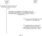
- FIG. 6 illustrates an interaction process of a terminal device and a charging base.
- a wireless communication connection has been established between a terminal device and a charging base.
- the interaction process of the terminal device and the charging base includes the following steps.
- the terminal device displays an interaction interface for heat dissipation control.
- the terminal device sends a control instruction corresponding to the selection information to the charging base based on selection information acting on the interaction interface for heat dissipation control.
- the charging base receives the control instruction sent by the terminal device.
- the charging base controls the fan based on the control instruction to dissipate heat at a rotation rate corresponding to the control instruction.
- the terminal device is for example, a mobile phone, a tablet computer, etc.
- the terminal device includes a control chip, a first charging chip and a display screen.
- the charging base is for example, a wireless charging device, and the charging base includes a second charging chip and a fan.
- FIG. 7 illustrates an interaction process of a terminal device and a charging base.
- a wireless communication connection has been established between a terminal device and a charging base.
- the interaction process of the terminal device and the charging base includes the following steps.
- the terminal device displays an interaction interface for heat dissipation control.
- a control instruction corresponding to the selection information is determined according to the configuration information and the selection information.
- a control instruction is sent to a charging base.
- the charging base receives the control instruction sent by the terminal device.
- the charging base controls the fan based on the control instruction to dissipate heat at a rotation rate corresponding to the control instruction.
- the terminal device is for example, a mobile phone, a tablet computer, etc.
- the terminal device includes a control chip, a first charging chip and a display screen.
- the charging base is for example, a wireless charging device, and the charging base includes a second charging chip and a fan.
- FIG. 8 illustrates an interaction process of a terminal device and a charging base.
- a wireless communication connection has been established between a terminal device and a charging base.
- the interaction process of the terminal device and the charging base includes the following steps.
- the terminal device displays an interaction interface for heat dissipation control.
- the terminal device sends a control instruction corresponding to the selection information to the charging base based on selection information acting on the interaction interface for heat dissipation control.
- the charging base receives the control instruction sent by the terminal device.
- the fan is controlled based on the control instruction in a form of a pulse width modulation signal, to dissipate heat at a rotation rate corresponding to the control instruction.
- the terminal device is for example, a mobile phone, a tablet computer, etc.
- the terminal device includes a control chip, a first charging chip and a display screen.
- the charging base is for example, a wireless charging device, and the charging base includes a second charging chip and a fan.
- FIG. 9 illustrates an interaction process of a terminal device and a charging base.
- a wireless communication connection has been established between a terminal device and a charging base.
- the interaction process of the terminal device and the charging base includes the following steps.
- the terminal device displays an interaction interface for heat dissipation control.
- the terminal device sends a control instruction corresponding to the selection information to the charging base based on selection information acting on the interaction interface for heat dissipation control.
- the charging base receives the control instruction sent by the terminal device.
- the pulse width modulation signal is parsed to determine a target rotation rate.
- the fan is controlled to dissipate heat at the target rotation rate based on the target rotation rate.
- the present disclosure provides an apparatus for heat dissipation control of a charging base, which is applied to a terminal device.
- the control apparatus in the embodiment includes a first receiving module 110, a display module 120 and a sending module 130.
- the apparatus in the embodiment is configured to implement the method as illustrated in FIG. 1 .
- the first receiving module 110 is configured to receive a trigger message configured to represent a wireless communication connection between the terminal device and the charging base.
- the display module 120 is configured to display an interaction interface for heat dissipation control according to the trigger message.
- the sending module 130 is configured to send a control instruction corresponding to the selection information to the charging base based on selection information acting on the interaction interface for heat dissipation control.
- the control instruction is sent to the charging base through the interaction interface for heat dissipation control in the terminal device, and the user may make selective adjustments to improve the intelligence of the charging base.
- the control apparatus in the embodiment includes a first receiving module 110, a display module 120 and a sending module 130.
- the apparatus in the embodiment is configured to implement the method as illustrated in FIG. 2 .
- the sending module 130 is configured to obtain configuration information; determine a control instruction corresponding to the selection information according to the configuration information and the selection information; and send the control instruction to the charging base.
- the present disclosure further provides an apparatus for heat dissipation control of a charging base.
- the apparatus is applied to a charging base including a fan, the charging base being connected to a terminal device through wireless communication.
- the control apparatus in the embodiment includes a second receiving module 210 and a control module 220.
- the apparatus in the embodiment is configured to implement the method as illustrated in FIG. 3 .
- the second receiving module 210 is configured to receive a control instruction sent by the terminal device.
- the control module 220 is configured to control the fan based on the control instruction to dissipate heat at a rotation rate corresponding to the control instruction.
- the charging base may receive the control instruction sent by the terminal device to adjust the rotation rate of the fan, which solves the shortage of being unable to manually adjust the rotation rate of the fan.
- the control apparatus in the embodiment includes a second receiving module 210 and a control module 220.
- the apparatus in the embodiment is configured to implement the method as illustrated in FIG. 4 .
- the control module 220 is configured to control the fan based on the control instruction in a form of a pulse width modulation signal, to dissipate heat at a rotation rate corresponding to the control instruction.
- the control apparatus in the embodiment includes a second receiving module 210 and a control module 220.
- the apparatus in the embodiment is configured to implement the method as illustrated in FIG. 5 .
- the control module 220 parses the pulse width modulation signal to determine a target rotation rate and controls the fan based on the target rotation rate to dissipate heat at the target rotation rate.
- FIG. 12 is a block diagram of an electronic device.
- the present disclosure provides an electronic device including a processor and a memory configured to store instructions executable by the processor.
- the electronic device may be configured as a terminal device when executing the method for heat dissipation control of a charging base as illustrated in FIG. 1 to FIG. 2 .
- the electronic device may be configured as a charging base when executing the method for heat dissipation control of a charging base as illustrated in FIG. 3 to FIG. 5 .
- the electronic device 300 may include one or more components: a processing component 302, a memory 304, an electrical component 306, a multimedia component 308, an audio component 310, an input/output (I/O) interface 312, a sensor component 314, and a communication component 316.
- the processing component 302 generally controls the whole operation of the electronic device 300, such as the operations related to displays, phone calls, data communication, camera operations and recording operations.
- the processing component 302 may include one or more processors 320 to perform instructions, to complete all or part of steps of the above method.
- the processing component 302 may include one or more modules for the convenience of interactions between the processing component 302 and other components.
- the processing component 302 may include a multimedia module for the convenience of interactions between the multimedia component 308 and the processing component 302.
- the memory 304 is configured to store various types of data to support the operation of the electronic device 300. Examples of such data include the instructions of any applications or methods operated on the electronic device 300, contact data, phone book data, messages, pictures, videos, etc.
- the memory 304 may be implemented by any type of volatile or nonvolatile storage devices or their combination, such as a static random-access memory (SRAM), an electrically erasable programmable read-only memory (EEPROM), an erasable programmable read-only memory (EPROM), a programmable read-only memory (PROM), a read-only memory (ROM), a magnetic memory, a flash memory, a magnetic disk or an optical disk.
- SRAM static random-access memory
- EEPROM electrically erasable programmable read-only memory
- EPROM erasable programmable read-only memory
- PROM programmable read-only memory
- ROM read-only memory
- magnetic memory a magnetic memory
- flash memory a flash memory
- the power supply component 306 may provide power for various components of the electronic device 300.
- the electrical component 306 may include a power supply management system, one or more power supplies, and other components related to generating, managing and distributing power for the device 300.
- the multimedia component 308 includes a screen that provides an output interface screen provided between the electronic device 300 and the user.
- a screen may include a liquid crystal display (LCD) and a touch panel (TP).
- the screen may be implemented as a touch screen to receive input signals from the user.
- the touch panel includes one or more touch sensors to sense touching, sliding and gestures on the touch panel. The touch sensor may not only sense the boundary of touching or sliding operation, but also detect the duration and pressure related to the touching or sliding operation.
- the multimedia component 308 includes a front camera and/or a rear camera. When the electronic device 300 is in operation mode, such as shooting mode or video mode, the front camera or the rear camera may receive external multimedia data.
- Each of the front camera and rear camera may be a fixed optical lens system or an optical lens system with focal length and optical zoom capacity.
- the audio component 310 is configured as output and/or input signals.
- the audio component 310 includes a microphone (MIC).
- MIC microphone
- the electronic device 300 is in operation mode, such as a call mode, a recording mode, and a speech recognition mode, the microphone is configured to receive external audio signals.
- the audio signals received may be further stored in the memory 304 or sent via the communication component 316.
- the audio component 310 further includes a speaker configured to output an audio signal.
- the I/O interface 312 provides an interface for the processing component 302 and the peripheral interface module, and the peripheral interface module may be a keyboard, a click wheel, a button, etc.
- the buttons may include but not limited to a home button, a volume button, a start button and a lock button.
- the sensor component 314 includes one or more sensors, configured to provide various aspects of state evaluation for the electronic device 300.
- the sensor component 314 may detect an on/off state of the electronic device 300 and the relative positioning of the component.
- the component is a display and a keypad of the electronic device 300.
- the sensor component 314 may further detect a location change of the electronic device 300 or a component of the electronic device 300, a presence or absence of user contact with the device 300, an orientation or an acceleration/deceleration of the device 300, and a temperature change of the device 300.
- the sensor component 314 may include a proximity sensor, which is configured to detect the presence of the objects nearby without any physical contact.
- the sensor component 314 may further include a light sensor such as CMOS or CCD image sensor, which is configured to use in imaging applications.
- the sensor component 314 may further include an acceleration transducer, a gyroscope sensor, a magnetic sensor, a pressure sensor or a temperature sensor.
- the communication component 316 is configured for the convenience of wire or wireless communication between the electronic device 300 and other devices.
- the electronic device 300 may access wireless networks based on communication standard, such as WiFi, 2G, 3G, 4G/LTE, 5G/NR or their combination.
- the communication component 316 receives broadcast signals or broadcast-related information from an external broadcast management system via a broadcast channel.
- the communication component 316 further includes a near field communication (NFC) module to facilitate short-range communication.
- the NFC module may be implemented based on a radio frequency identification (RFID) technology, an infrared data association (IRDA) technology, an ultra-wideband (UWB) technology, a bluetooth (BT) technology and other technologies.
- RFID radio frequency identification
- IRDA infrared data association
- UWB ultra-wideband
- BT bluetooth
- the electronic device 300 may be implemented by one or more application specific integrated circuits (ASIC), digital signal processors (DSP), digital signal processing devices (DSPD), programmable logic devices (PLD), field programmable gate arrays (FPGA), controllers, microcontrollers, microprocessors or other electronics components, which is configured to perform the above method.
- ASIC application specific integrated circuits
- DSP digital signal processors
- DSPD digital signal processing devices
- PLD programmable logic devices
- FPGA field programmable gate arrays
- controllers microcontrollers, microprocessors or other electronics components, which is configured to perform the above method.
- a non-transitory computer readable storage medium is further provided, such as the memory 304 including instructions, in which the instructions is caused to be executed by the processor 320 of the electronic device 300 to complete the above methods.
- the computer readable storage medium may be a ROM, a random access memory (RAM), a CD-ROM, a magnetic tape, a floppy disk, an optical data storage device, etc.
- a terminal device may execute a method as described in FIG. 1 to FIG. 2 when instructions in the storage medium are executed by the processor of an electronic device.
- a charging base may execute a method as described in FIG. 3 to FIG. 5 when instructions in the storage medium are executed by the charging base.
Landscapes
- Engineering & Computer Science (AREA)
- Power Engineering (AREA)
- Microelectronics & Electronic Packaging (AREA)
- Physics & Mathematics (AREA)
- Thermal Sciences (AREA)
- Computer Networks & Wireless Communication (AREA)
- General Engineering & Computer Science (AREA)
- General Physics & Mathematics (AREA)
- Automation & Control Theory (AREA)
- Charge And Discharge Circuits For Batteries Or The Like (AREA)
- Telephone Function (AREA)
Applications Claiming Priority (1)
| Application Number | Priority Date | Filing Date | Title |
|---|---|---|---|
| CN202110330503.5A CN115133595B (zh) | 2021-03-25 | 2021-03-25 | 充电座散热控制方法、装置、终端设备、充电座及介质 |
Publications (2)
| Publication Number | Publication Date |
|---|---|
| EP4064508A1 true EP4064508A1 (de) | 2022-09-28 |
| EP4064508B1 EP4064508B1 (de) | 2026-04-29 |
Family
ID=77864317
Family Applications (1)
| Application Number | Title | Priority Date | Filing Date |
|---|---|---|---|
| EP21194062.2A Active EP4064508B1 (de) | 2021-03-25 | 2021-08-31 | Verfahren und vorrichtung zur wärmeableitungssteuerung einer ladestation und endgerätevorrichtung |
Country Status (3)
| Country | Link |
|---|---|
| US (1) | US11812593B2 (de) |
| EP (1) | EP4064508B1 (de) |
| CN (1) | CN115133595B (de) |
Families Citing this family (2)
| Publication number | Priority date | Publication date | Assignee | Title |
|---|---|---|---|---|
| FR3133716B1 (fr) * | 2022-03-16 | 2026-01-30 | St Microelectronics Rousset | Procédé de communication |
| CN119275958B (zh) * | 2024-03-21 | 2025-09-05 | 荣耀终端股份有限公司 | 无线充电的方法及电子设备 |
Citations (2)
| Publication number | Priority date | Publication date | Assignee | Title |
|---|---|---|---|---|
| CN210603615U (zh) * | 2019-09-12 | 2020-05-22 | 北京首钢股份有限公司 | 一种电力系统温度检测装置 |
| CN112152304A (zh) * | 2020-09-10 | 2020-12-29 | 军事科学院系统工程研究院军事新能源技术研究所 | 一种微波场型无线充电控制方法 |
Family Cites Families (5)
| Publication number | Priority date | Publication date | Assignee | Title |
|---|---|---|---|---|
| JP2005276733A (ja) * | 2004-03-26 | 2005-10-06 | Hitachi Koki Co Ltd | 充電装置 |
| JP6212910B2 (ja) * | 2013-04-01 | 2017-10-18 | マックス株式会社 | 電池パック |
| US10222829B2 (en) * | 2015-12-09 | 2019-03-05 | Lenovo (Singapore) Pte. Ltd. | Systems and methods to cool mobile device using thermoelectric cooler |
| US10481656B2 (en) * | 2015-12-10 | 2019-11-19 | Dell Products L.P. | Systems and methods for cooling portable information handling systems |
| KR102469564B1 (ko) * | 2017-03-24 | 2022-11-22 | 삼성전자주식회사 | 전자 장치의 상태에 따른 외부 장치 제어 방법 및 장치 |
-
2021
- 2021-03-25 CN CN202110330503.5A patent/CN115133595B/zh active Active
- 2021-08-30 US US17/461,242 patent/US11812593B2/en active Active
- 2021-08-31 EP EP21194062.2A patent/EP4064508B1/de active Active
Patent Citations (2)
| Publication number | Priority date | Publication date | Assignee | Title |
|---|---|---|---|---|
| CN210603615U (zh) * | 2019-09-12 | 2020-05-22 | 北京首钢股份有限公司 | 一种电力系统温度检测装置 |
| CN112152304A (zh) * | 2020-09-10 | 2020-12-29 | 军事科学院系统工程研究院军事新能源技术研究所 | 一种微波场型无线充电控制方法 |
Also Published As
| Publication number | Publication date |
|---|---|
| CN115133595A (zh) | 2022-09-30 |
| US11812593B2 (en) | 2023-11-07 |
| EP4064508B1 (de) | 2026-04-29 |
| CN115133595B (zh) | 2024-12-17 |
| US20220312650A1 (en) | 2022-09-29 |
Similar Documents
| Publication | Publication Date | Title |
|---|---|---|
| EP3745790B1 (de) | Verfahren und vorrichtung zur informationskonfiguration, verfahren und vorrichtung zur bestimmung eines zeitfrequenortes und basisstation | |
| RU2471223C2 (ru) | Мобильный терминал и способ управления передачей данных связи и устройство отображения списка связи в нем | |
| JP6334688B2 (ja) | メッセージ送信方法、メッセージ受信方法および装置 | |
| EP3917116B1 (de) | Erkennung eines maximalen übertragungseinheitswerts | |
| KR20150141039A (ko) | 웨어러블 전자 장치, 메인 전자 장치, 시스템 및 그 제어 방법 | |
| CN112269556A (zh) | 信息展示方法、装置、系统、设备、服务器及存储介质 | |
| EP4064508B1 (de) | Verfahren und vorrichtung zur wärmeableitungssteuerung einer ladestation und endgerätevorrichtung | |
| WO2016155304A1 (zh) | 无线访问接入点的控制方法及装置 | |
| CN108965413B (zh) | 信息交互方法、装置及存储介质 | |
| WO2021233134A1 (zh) | 基于ble的通讯方法、装置、设备、系统以及存储介质 | |
| CN111541922A (zh) | 显示界面输入信息的方法、装置及存储介质 | |
| EP1986406A2 (de) | System und Verfahren zur Erkennung einer externen Vorrichtung mittels tragbarem Endgerät | |
| CN106506808B (zh) | 对通讯消息提示的方法及装置 | |
| CN114791974A (zh) | 模型服务处理方法、装置及设备 | |
| WO2019227318A1 (zh) | 物理下行控制信道监测配置、监测方法及装置和基站 | |
| US11297626B2 (en) | Information indication method and apparatus, base station and user equipment | |
| CN111399796A (zh) | 语音消息聚合方法、装置、电子设备及存储介质 | |
| CN113885693A (zh) | 触控反馈模组及方法、电子设备、计算机存储介质 | |
| CN112019681B (zh) | 移动终端的控制方法、移动终端及存储介质 | |
| CN105897558A (zh) | 消息发送方法、消息接收方法及终端 | |
| CN113922457A (zh) | 充电方法、装置、电子设备及存储介质 | |
| CN115276137A (zh) | 充电控制方法及装置 | |
| CN109962757A (zh) | 基于视联网的数据传输方法及装置 | |
| CN113078697A (zh) | 充电控制方法及装置、转接器 | |
| WO2025001410A1 (zh) | 一种蓝牙助听器连接方法、电子设备及装置 |
Legal Events
| Date | Code | Title | Description |
|---|---|---|---|
| PUAI | Public reference made under article 153(3) epc to a published international application that has entered the european phase |
Free format text: ORIGINAL CODE: 0009012 |
|
| STAA | Information on the status of an ep patent application or granted ep patent |
Free format text: STATUS: THE APPLICATION HAS BEEN PUBLISHED |
|
| AK | Designated contracting states |
Kind code of ref document: A1 Designated state(s): AL AT BE BG CH CY CZ DE DK EE ES FI FR GB GR HR HU IE IS IT LI LT LU LV MC MK MT NL NO PL PT RO RS SE SI SK SM TR |
|
| STAA | Information on the status of an ep patent application or granted ep patent |
Free format text: STATUS: REQUEST FOR EXAMINATION WAS MADE |
|
| 17P | Request for examination filed |
Effective date: 20230320 |
|
| RBV | Designated contracting states (corrected) |
Designated state(s): AL AT BE BG CH CY CZ DE DK EE ES FI FR GB GR HR HU IE IS IT LI LT LU LV MC MK MT NL NO PL PT RO RS SE SI SK SM TR |
|
| GRAP | Despatch of communication of intention to grant a patent |
Free format text: ORIGINAL CODE: EPIDOSNIGR1 |
|
| STAA | Information on the status of an ep patent application or granted ep patent |
Free format text: STATUS: GRANT OF PATENT IS INTENDED |
|
| INTG | Intention to grant announced |
Effective date: 20251208 |
|
| GRAS | Grant fee paid |
Free format text: ORIGINAL CODE: EPIDOSNIGR3 |
|
| GRAA | (expected) grant |
Free format text: ORIGINAL CODE: 0009210 |
|
| STAA | Information on the status of an ep patent application or granted ep patent |
Free format text: STATUS: THE PATENT HAS BEEN GRANTED |
|
| AK | Designated contracting states |
Kind code of ref document: B1 Designated state(s): AL AT BE BG CH CY CZ DE DK EE ES FI FR GB GR HR HU IE IS IT LI LT LU LV MC MK MT NL NO PL PT RO RS SE SI SK SM TR |
|
| REG | Reference to a national code |
Ref country code: CH Ref legal event code: F10 Free format text: ST27 STATUS EVENT CODE: U-0-0-F10-F00 (AS PROVIDED BY THE NATIONAL OFFICE) Effective date: 20260429 |