EP4064449B1 - Box body for battery, battery, electric apparatus, and battery manufacturing method and device - Google Patents
Box body for battery, battery, electric apparatus, and battery manufacturing method and device Download PDFInfo
- Publication number
- EP4064449B1 EP4064449B1 EP20957976.2A EP20957976A EP4064449B1 EP 4064449 B1 EP4064449 B1 EP 4064449B1 EP 20957976 A EP20957976 A EP 20957976A EP 4064449 B1 EP4064449 B1 EP 4064449B1
- Authority
- EP
- European Patent Office
- Prior art keywords
- box body
- liquid
- battery
- gravity
- wall
- Prior art date
- Legal status (The legal status is an assumption and is not a legal conclusion. Google has not performed a legal analysis and makes no representation as to the accuracy of the status listed.)
- Active
Links
Images


Classifications
-
- H—ELECTRICITY
- H01—ELECTRIC ELEMENTS
- H01M—PROCESSES OR MEANS, e.g. BATTERIES, FOR THE DIRECT CONVERSION OF CHEMICAL ENERGY INTO ELECTRICAL ENERGY
- H01M50/00—Constructional details or processes of manufacture of the non-active parts of electrochemical cells other than fuel cells, e.g. hybrid cells
- H01M50/60—Arrangements or processes for filling or topping-up with liquids; Arrangements or processes for draining liquids from casings
- H01M50/691—Arrangements or processes for draining liquids from casings; Cleaning battery or cell casings
-
- A—HUMAN NECESSITIES
- A62—LIFE-SAVING; FIRE-FIGHTING
- A62C—FIRE-FIGHTING
- A62C3/00—Fire prevention, containment or extinguishing specially adapted for particular objects or places
- A62C3/16—Fire prevention, containment or extinguishing specially adapted for particular objects or places in electrical installations, e.g. cableways
-
- H—ELECTRICITY
- H01—ELECTRIC ELEMENTS
- H01M—PROCESSES OR MEANS, e.g. BATTERIES, FOR THE DIRECT CONVERSION OF CHEMICAL ENERGY INTO ELECTRICAL ENERGY
- H01M10/00—Secondary cells; Manufacture thereof
- H01M10/04—Construction or manufacture in general
- H01M10/0404—Machines for assembling batteries
-
- H—ELECTRICITY
- H01—ELECTRIC ELEMENTS
- H01M—PROCESSES OR MEANS, e.g. BATTERIES, FOR THE DIRECT CONVERSION OF CHEMICAL ENERGY INTO ELECTRICAL ENERGY
- H01M10/00—Secondary cells; Manufacture thereof
- H01M10/42—Methods or arrangements for servicing or maintenance of secondary cells or secondary half-cells
-
- H—ELECTRICITY
- H01—ELECTRIC ELEMENTS
- H01M—PROCESSES OR MEANS, e.g. BATTERIES, FOR THE DIRECT CONVERSION OF CHEMICAL ENERGY INTO ELECTRICAL ENERGY
- H01M10/00—Secondary cells; Manufacture thereof
- H01M10/60—Heating or cooling; Temperature control
-
- H—ELECTRICITY
- H01—ELECTRIC ELEMENTS
- H01M—PROCESSES OR MEANS, e.g. BATTERIES, FOR THE DIRECT CONVERSION OF CHEMICAL ENERGY INTO ELECTRICAL ENERGY
- H01M10/00—Secondary cells; Manufacture thereof
- H01M10/60—Heating or cooling; Temperature control
- H01M10/61—Types of temperature control
- H01M10/613—Cooling or keeping cold
-
- H—ELECTRICITY
- H01—ELECTRIC ELEMENTS
- H01M—PROCESSES OR MEANS, e.g. BATTERIES, FOR THE DIRECT CONVERSION OF CHEMICAL ENERGY INTO ELECTRICAL ENERGY
- H01M10/00—Secondary cells; Manufacture thereof
- H01M10/60—Heating or cooling; Temperature control
- H01M10/62—Heating or cooling; Temperature control specially adapted for specific applications
- H01M10/625—Vehicles
-
- H—ELECTRICITY
- H01—ELECTRIC ELEMENTS
- H01M—PROCESSES OR MEANS, e.g. BATTERIES, FOR THE DIRECT CONVERSION OF CHEMICAL ENERGY INTO ELECTRICAL ENERGY
- H01M50/00—Constructional details or processes of manufacture of the non-active parts of electrochemical cells other than fuel cells, e.g. hybrid cells
- H01M50/20—Mountings; Secondary casings or frames; Racks, modules or packs; Suspension devices; Shock absorbers; Transport or carrying devices; Holders
- H01M50/202—Casings or frames around the primary casing of a single cell or a single battery
-
- H—ELECTRICITY
- H01—ELECTRIC ELEMENTS
- H01M—PROCESSES OR MEANS, e.g. BATTERIES, FOR THE DIRECT CONVERSION OF CHEMICAL ENERGY INTO ELECTRICAL ENERGY
- H01M50/00—Constructional details or processes of manufacture of the non-active parts of electrochemical cells other than fuel cells, e.g. hybrid cells
- H01M50/20—Mountings; Secondary casings or frames; Racks, modules or packs; Suspension devices; Shock absorbers; Transport or carrying devices; Holders
- H01M50/204—Racks, modules or packs for multiple batteries or multiple cells
-
- H—ELECTRICITY
- H01—ELECTRIC ELEMENTS
- H01M—PROCESSES OR MEANS, e.g. BATTERIES, FOR THE DIRECT CONVERSION OF CHEMICAL ENERGY INTO ELECTRICAL ENERGY
- H01M50/00—Constructional details or processes of manufacture of the non-active parts of electrochemical cells other than fuel cells, e.g. hybrid cells
- H01M50/20—Mountings; Secondary casings or frames; Racks, modules or packs; Suspension devices; Shock absorbers; Transport or carrying devices; Holders
- H01M50/233—Mountings; Secondary casings or frames; Racks, modules or packs; Suspension devices; Shock absorbers; Transport or carrying devices; Holders characterised by physical properties of casings or racks, e.g. dimensions
- H01M50/24—Mountings; Secondary casings or frames; Racks, modules or packs; Suspension devices; Shock absorbers; Transport or carrying devices; Holders characterised by physical properties of casings or racks, e.g. dimensions adapted for protecting batteries from their environment, e.g. from corrosion
-
- H—ELECTRICITY
- H01—ELECTRIC ELEMENTS
- H01M—PROCESSES OR MEANS, e.g. BATTERIES, FOR THE DIRECT CONVERSION OF CHEMICAL ENERGY INTO ELECTRICAL ENERGY
- H01M50/00—Constructional details or processes of manufacture of the non-active parts of electrochemical cells other than fuel cells, e.g. hybrid cells
- H01M50/20—Mountings; Secondary casings or frames; Racks, modules or packs; Suspension devices; Shock absorbers; Transport or carrying devices; Holders
- H01M50/249—Mountings; Secondary casings or frames; Racks, modules or packs; Suspension devices; Shock absorbers; Transport or carrying devices; Holders specially adapted for aircraft or vehicles, e.g. cars or trains
-
- H—ELECTRICITY
- H01—ELECTRIC ELEMENTS
- H01M—PROCESSES OR MEANS, e.g. BATTERIES, FOR THE DIRECT CONVERSION OF CHEMICAL ENERGY INTO ELECTRICAL ENERGY
- H01M50/00—Constructional details or processes of manufacture of the non-active parts of electrochemical cells other than fuel cells, e.g. hybrid cells
- H01M50/20—Mountings; Secondary casings or frames; Racks, modules or packs; Suspension devices; Shock absorbers; Transport or carrying devices; Holders
- H01M50/271—Lids or covers for the racks or secondary casings
-
- H—ELECTRICITY
- H01—ELECTRIC ELEMENTS
- H01M—PROCESSES OR MEANS, e.g. BATTERIES, FOR THE DIRECT CONVERSION OF CHEMICAL ENERGY INTO ELECTRICAL ENERGY
- H01M50/00—Constructional details or processes of manufacture of the non-active parts of electrochemical cells other than fuel cells, e.g. hybrid cells
- H01M50/30—Arrangements for facilitating escape of gases
- H01M50/394—Gas-pervious parts or elements
-
- H—ELECTRICITY
- H01—ELECTRIC ELEMENTS
- H01M—PROCESSES OR MEANS, e.g. BATTERIES, FOR THE DIRECT CONVERSION OF CHEMICAL ENERGY INTO ELECTRICAL ENERGY
- H01M50/00—Constructional details or processes of manufacture of the non-active parts of electrochemical cells other than fuel cells, e.g. hybrid cells
- H01M50/50—Current conducting connections for cells or batteries
- H01M50/572—Means for preventing undesired use or discharge
- H01M50/584—Means for preventing undesired use or discharge for preventing incorrect connections inside or outside the batteries
-
- H—ELECTRICITY
- H01—ELECTRIC ELEMENTS
- H01M—PROCESSES OR MEANS, e.g. BATTERIES, FOR THE DIRECT CONVERSION OF CHEMICAL ENERGY INTO ELECTRICAL ENERGY
- H01M50/00—Constructional details or processes of manufacture of the non-active parts of electrochemical cells other than fuel cells, e.g. hybrid cells
- H01M50/60—Arrangements or processes for filling or topping-up with liquids; Arrangements or processes for draining liquids from casings
- H01M50/609—Arrangements or processes for filling with liquid, e.g. electrolytes
- H01M50/627—Filling ports
-
- H—ELECTRICITY
- H01—ELECTRIC ELEMENTS
- H01M—PROCESSES OR MEANS, e.g. BATTERIES, FOR THE DIRECT CONVERSION OF CHEMICAL ENERGY INTO ELECTRICAL ENERGY
- H01M50/00—Constructional details or processes of manufacture of the non-active parts of electrochemical cells other than fuel cells, e.g. hybrid cells
- H01M50/60—Arrangements or processes for filling or topping-up with liquids; Arrangements or processes for draining liquids from casings
- H01M50/673—Containers for storing liquids; Delivery conduits therefor
- H01M50/682—Containers for storing liquids; Delivery conduits therefor accommodated in battery or cell casings
-
- H—ELECTRICITY
- H01—ELECTRIC ELEMENTS
- H01M—PROCESSES OR MEANS, e.g. BATTERIES, FOR THE DIRECT CONVERSION OF CHEMICAL ENERGY INTO ELECTRICAL ENERGY
- H01M2220/00—Batteries for particular applications
- H01M2220/20—Batteries in motive systems, e.g. vehicle, ship, plane
-
- Y—GENERAL TAGGING OF NEW TECHNOLOGICAL DEVELOPMENTS; GENERAL TAGGING OF CROSS-SECTIONAL TECHNOLOGIES SPANNING OVER SEVERAL SECTIONS OF THE IPC; TECHNICAL SUBJECTS COVERED BY FORMER USPC CROSS-REFERENCE ART COLLECTIONS [XRACs] AND DIGESTS
- Y02—TECHNOLOGIES OR APPLICATIONS FOR MITIGATION OR ADAPTATION AGAINST CLIMATE CHANGE
- Y02E—REDUCTION OF GREENHOUSE GAS [GHG] EMISSIONS, RELATED TO ENERGY GENERATION, TRANSMISSION OR DISTRIBUTION
- Y02E60/00—Enabling technologies; Technologies with a potential or indirect contribution to GHG emissions mitigation
- Y02E60/10—Energy storage using batteries
Definitions
- This application relates to the field of battery technologies, and in particular, to a box body applied to battery, a battery, an electric apparatus, and a method and device for preparing battery.
- the batteries in the prior art are usually equipped with thermal management components for cooling or heating the batteries.
- thermal management components for cooling or heating the batteries.
- all components coming in contact with the thermal management component in a box body produce a condensate, and the condensate comes in contact with an electric structure in the box body and then causes a short circuit.
- CN 207 441 762 U discloses a box assembly and a battery box that can discharge the liquid that has infiltrated into the box and improve the safety performance of the battery box.
- the battery box has a box body having a bottom wall 111 with groove C positioned lower than the surface of bottom wall 111. A liquid is collected in groove C so that it can flow into mounting hole H, in which a one-way valve 12 is fixed.
- This application provides a box body applied to battery, a battery, an electric apparatus, and a method and device for preparing battery, so as to prevent short circuits of a battery caused by a condensate.
- a first aspect of this application provides a box body applied to battery, including:
- the one-way gravity valve includes:
- the box body further includes a thermal management component, the thermal management component is configured to adjust a temperature of the battery, the thermal management component intersects the first wall, a first portion of the condensing part extends along the thermal management component, so as to be attached to the thermal management component, and a second portion of the condensing part extends along the first wall to block the vent hole.
- the thermal management component is configured to adjust a temperature of the battery
- the thermal management component intersects the first wall
- a first portion of the condensing part extends along the thermal management component, so as to be attached to the thermal management component
- a second portion of the condensing part extends along the first wall to block the vent hole.
- the cover-like structure is attached to a surrounding region of the vent hole on the first wall, and is provided with a first opening through which gas flows into the box body.
- the first opening is further configured to collect fluid leaked from a joint of a pipe of the fire prevention system in a case of fluid leakage at the joint.
- a projection surface of the cover-like structure on the first wall is a U-shaped surface, a V-shaped surface, or a rectangular surface.
- portions of the condensing part on two sides of the flow channel are attached to the first wall.
- the second opening is provided in a second direction of the cover-like structure, and the second direction is the direction of gravity.
- the one-way gravity valve is further configured to discharge the condensate out of the box body from the flow channel when a gravity of the condensate in the flow channel reaches the threshold.
- the box body further includes a pressure balance mechanism, configured to balance pressure inside and outside the box body.
- the pressure balance mechanism is provided on the second sub-wall, and gas flowing from outside the box body to the hollow chamber through the pressure balance mechanism flows into the box body through the vent hole.
- the box body further includes a liquid storage member disposed on the inner surface of the box body, and the liquid storage member is configured to, when the height of the liquid surface of the liquid in the box body in the direction of gravity reaches a height of the liquid storage member, store liquid that flows into the liquid storage member, and discharge the liquid flowing into the liquid storage member to the one-way gravity valve.
- a second aspect of this application provides a battery, including the foregoing box body, where the box body is configured to accommodate the battery.
- a third aspect of this application provides an electric apparatus, including the foregoing battery, where the battery is configured to supply electrical energy.
- a fourth aspect of this application provides a method for preparing battery, including:
- a fifth aspect of this application provides a device for preparing battery, including:
- the box body applied to battery according to the embodiments of this application is provided with the one-way gravity valve, and a time for discharging the liquid in the box body is determined based on the threshold of the one-way gravity valve.
- the liquid in the box body can be discharged in a timely manner, so as to avoid holding up excessive liquid in the box body for a long time and reduce safety hazards such as short circuits and improving service life of the battery.
- the small amount of liquid in the box body can play a role of cooling the battery inside the box body under the premise of not affecting safety performance of the battery.
- the terms “mounting”, “interconnection”, and “connection” should be understood in a broad sense.
- the “interconnection” or “connection” of a mechanical structure may be a physical connection.
- the physical connection may be a fixed connection, for example, a fixed connection by using a fastener, such as a fixed connection by using a screw, a bolt, or another fastener; or the physical connection may be a detachable connection, such as a clamping or buckling connection; or the physical connection may be an integrated connection, for example, a connection through welding, bonding, or integral molding.
- connection or “connection” of a circuit structure may be a physical connection, or may be an electrical connection or a signal connection.
- the "interconnection” or “connection” of the circuit structure may be a direct connection, that is, a physical connection; or may be an indirect connection through at least one intermediate element, provided that the circuit is connected; or may be an internal connection between two elements.
- the signal connection may be a signal connection through a circuit, or may be a signal connection through a medium, such as a radio wave. Persons of ordinary skill in the art can understand specific meanings of these terms in this application based on specific situations.
- orientations or positional relationships indicated by the terms such as “center”, “longitudinal”, “lateral”, “length”, “width”, “thickness”, “up”, “down”, “front”, “rear”, “left”, “right”, “vertical”, “horizontal”, “top”, “bottom”, “inside”, “outside”, “clockwise”, “counterclockwise”, “axial”, “radial”, and “circumferential” are based on the orientations or positional relationships shown in the accompanying drawings, are merely intended to facilitate the descriptions of this application and simplify the descriptions, are not intended to indicate or imply that the apparatuses or components mentioned in this application must have specific orientations, or be constructed and operated for a specific orientation, and therefore shall not be construed as a limitation to this application.
- the rechargeable battery may be referred to as a secondary battery or a traction battery.
- rechargeable batteries are lithium-ion batteries, for example, lithium-sulfur batteries, sodium lithium-ion batteries, or magnesium ion batteries, which are not limited thereto.
- the rechargeable battery herein may be collectively referred to as a battery.
- a safety property of the battery is an important property to evaluate the battery. Safety of the battery needs to be guaranteed to a maximum extent during use or charging.
- the inventor coated a conductive member in the box body with an insulation material to prevent the conductive member from coming in contact with the condensate to cause a short circuit.
- the inventor found that such coating was difficult to completely cover the conductive member; in addition, such coating was more difficult for irregular-shaped conductive members. Based on this, the inventor attempted to discharge excessive condensates condensed by the thermal management component of the box body out of the box body, so as to resolve safety problems such as short circuits.
- this application provides a box body applied to battery, so as to discharge a condensate out of the battery and prevent a large amount of condensate from accumulating inside the battery for a long time to cause potential safety hazards.
- the condensate can be discharged out of the battery in a timely manner, and the condensate outside the pipe wall of the pipe connected to the thermal management component can also be located in a position convenient for discharging, thereby further reducing impact of the condensate on the battery, for example, reducing a risk of short circuits of the battery cell caused by excessive condensate.
- the battery in this embodiment of this application can be applied to various electric apparatuses capable of using electrical energy as a power source.
- the electric apparatus herein may be, but not limited to, an electric vehicle, an electric train, an electric bicycle, a golf cart, a ship, a drone, or the like.
- the electric apparatus may be an apparatus that uses only the battery as a power source, or may be a hybrid electric apparatus.
- the battery provides electrical energy for the electric apparatus, and drives the electric apparatus to travel through the motor.
- FIG. 1-A is a schematic structural diagram of an electric apparatus according to an embodiment of this application.
- the electric apparatus may be a vehicle, and the vehicle may be an oil-fueled vehicle, a gas-fueled vehicle, or a new energy vehicle.
- the new energy vehicle may be a battery electric vehicle, a hybrid electric vehicle, an extended-range vehicle, or the like.
- the vehicle includes a battery 200, a controller 210, and a motor 220.
- the battery 200 is configured to supply power to the controller 210 and the motor 220 as an operating power source and a driving power source of the vehicle.
- the battery 200 is configured to meet an operating power requirement of the vehicle during startup, navigation, and operating.
- the battery 200 supplies power to the controller 210, and the controller 210 controls the battery 200 to supply power to the motor 220.
- the motor 220 receives and uses the power of the battery 200 as a driving power source for the vehicle, to replace or partially replace fuel or natural gas to provide driving power for the vehicle.
- the battery 200 may include a plurality of battery modules electrically connected to each other. As shown in FIG. 1-B , the battery 200 includes a first box body 201, a second box body 202, and a plurality of battery modules 300. The first box body 201 and the second box body 202 are fastened together, and the plurality of battery modules 300 are arranged in a space enclosed by the first box body 201 and the second box body 202. In some embodiments, the first box body 201 and the second box body 202 are connected in a sealed manner.
- the battery module 300 includes a plurality of battery cells 400, and the plurality of battery cells 400 may be electrically connected in a series, parallel, or hybrid manner to implement a larger current or voltage.
- the hybrid connection refers to a combination of series connection and parallel connection.
- the battery cell 400 may be placed vertically, a height direction of the battery cell 400 is consistent with the direction z, a length direction of the battery cell 400 is consistent with the direction x, and a plurality of battery cells 400 is arranged side by side along a width direction in the direction y.
- the battery cell 400 may be laid flat, the width direction of the battery cell 400 is consistent with the direction z, the length direction of the battery cell 400 is consistent with the direction x, and the plurality of battery cells 400 are stacked for at least one layer along the direction z.
- Each layer includes a plurality of battery cells 400 spaced apart along the direction x.
- the battery cell 400 includes a housing body 40, an electrode assembly 30, and an end cover assembly 10.
- the end cover assembly 10 includes an end cover plate 10', and the end cover plate 10' is connected (for example, being welded) to the housing body 40, to form a housing of the battery cell 400.
- the electrode assembly 30 is disposed in the housing body 40, and the housing body 40 is filled with electrolyte.
- the battery cell 400 may be of a cubic shape, a rectangular shape, or a cylindrical shape.
- the tab 301 of the electrode assembly 30 is located at the top, the positive tab is connected to the positive terminal through one connecting member 20, and the negative tab is connected to the negative terminal through the other connecting member 20.
- the battery cell 400 may include two end cover assemblies 10, respectively disposed at two ends of the housing body 40, and each end cover assembly 10 is provided with one electrode terminal 5.
- Actuate described in this application means that the pressure relief mechanism 6 performs an action or is activated to a specific state, so that the internal pressure of the battery cell 400 can be relieved.
- the action performed by the pressure relief mechanism 6 may include but is not limited to: cracking, breaking, tearing, or opening at least part of the pressure relief mechanism 6, or the like.
- the end cover plate 10' is provided with a through hole for injecting the electrolyte into the battery cell 400.
- the through hole may be a round hole, an elliptical hole, a polygonal hole, or holes of other shapes, and may extend along the height direction of the end cover plate 10'.
- the end cover plate 10 is provided with an injection member 2 for closing the through hole.
- a box body 500 applied to battery 200 provided in this embodiment of this application includes a carrying plate 510 and a one-way gravity valve 520.
- the carrying plate 510 is mainly configured to carry the battery 200
- the one-way gravity valve 520 is provided on the carrying plate 510, and is configured to be closed when a gravity of liquid in the box body 500 is less than a threshold; and to be open when the gravity of the liquid in the box body 500 reaches the threshold, so as to discharge the liquid through the one-way gravity valve 520.
- the carrying plate 510 for carrying the battery 200 is usually disposed at the bottom of the box body 500. Therefore, the one-way gravity valve 520 disposed on the carrying plate 510 is also disposed at the bottom of the box body 500, helping discharge the liquid out of the box body 500.
- the device in use is the one-way gravity valve 520
- the one-way gravity valve 520 includes a liquid discharge member 521 and a movable assembly 522.
- the liquid discharge member 521 has a first through hole 523, and the liquid discharge member 521 is configured to discharge the liquid such as the condensate and emissions through the first through hole 523 when the gravity of the liquid in the box body 500 reaches the threshold.
- the movable assembly 522 is installed on the liquid discharge member 521 and capable of moving relative to the first through hole 523, so that the movable assembly 522 seals the first through hole 523 when the gravity of the liquid in the box body 500 is less than the threshold, and opens the first through hole 523 when the gravity of the liquid in the box body 500 reaches the threshold.
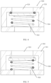
- FIG. 4 shows a case that the movable assembly 522 seals the first through hole 523 when the gravity of the liquid in the box body 500 is less than the threshold, so as to play a role of sealing the box body 500 when there is a small amount of liquid or no liquid in the box body 500.
- FIG. 5 shows a case that the movable assembly 522 opens the first through hole 523 when the gravity of the liquid in the box body 500 reaches the threshold, so as to open the first through hole 523 to discharge the liquid when there is a large amount of liquid needing to be discharged out of the box body 500. This avoids holding up the liquid in the box body 500 for a long time to affect normal use of the battery 200.
- the movable assembly 522 may be disposed at the bottom of the first through hole 523, or may be disposed on the side wall of the first through hole 523, which is not particularly limited in this embodiment of this application.
- the liquid discharge member 521 may have an accommodating chamber 524, and the movable assembly 522 may be disposed in the accommodating chamber 524 and is capable of moving up and down in the accommodating chamber 524.
- the movable assembly 522 moves up and down in the accommodating chamber 524 to seal or open the first through hole 523.
- the movable assembly 522 further includes a sealing member 5221 and an elastic member 5222.
- the sealing member 5221 is movably connected to the accommodating chamber 524 to seal or open the first through hole 523.
- the elastic member 5222 is configured to provide a preset supporting force to the sealing member 5221, and the preset supporting force is the same as the threshold, so that the sealing member 5221 can seal the first through hole 523 when the gravity of the liquid in the box body 500 is less than the preset supporting force, and open the first through hole 523 when the gravity of the liquid in the box body 500 reaches the preset supporting force, to discharge the liquid.
- the box body 500 provided in this embodiment of this application further includes a bottom plate 530.
- the bottom plate 530 is configured to connect to the carrying plate 510 to form a water storage chamber.
- the water storage chamber communicates with the first through hole 523, so as to collect the liquid discharged from the first through hole 523, thereby preventing the liquid out of the box body 500 from directly flowing to the electric apparatus using the battery 200 to cause safety hazards.
- the first sub-wall 5401 is provided with the liquid discharge hole 5403, that is, the liquid discharge hole 5403 penetrates through only the first sub-wall 5401 of the first wall 540, so that the liquid whose height of the liquid surface in the direction of gravity is greater than or equal to that of the liquid discharge hole 5403 is collected in the hollow chamber and the liquid in the box body 500 can be discharged in a timely manner.
- the condensing part 550 is disposed on the inner surface of the box body 500 at a position opposite the vent hole 5404, so that gas flowing from the vent hole 5404 first comes in contact with the condensing part 550, to achieve a purpose of preventing the gas from condensing in the box body and then coming in contact with conductive members inside the box body.
- the box body 500 further includes a thermal management component 560.
- the thermal management component 560 is configured to adjust a temperature of the battery 200.
- the thermal management component 560 intersects the first wall 540 to enter the box body 500 through the first wall 540, thereby implementing temperature adjustment for the battery 200.
- the thermal management component 560 may be a component such as a water cooling plate, which is not particularly limited in this embodiment of this application.
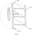
- the cover-like structure of the condensing part 550 is further provided with a flow channel 5502, and the flow channel 5502 is configured to guide the condensate of the cover-like structure to the one-way gravity valve 520. Portions of the condensing part 550 on two sides of the flow channel 5502 are attached to the first wall 540.
- the cover-like structure has a second opening 5503 corresponding to the flow channel 5502, and the second opening 5503 is configured to guide the condensate on the cover-like structure to the flow channel 5502 and then into the one-way gravity valve 520 through the flow channel 5502.
- the one-way gravity valve 520 is further configured to discharge the condensate out of the box body 500 from the flow channel 5502 when a gravity of the condensate in the flow channel 5502 reaches the threshold.
- the second opening 5503 is provided in a second direction of the cover-like structure, and the second direction is the direction of gravity.
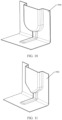
- the box body 500 further includes a liquid storage member 580 disposed on the inner surface of the box body 500, and the liquid storage member 580 is configured to, when the height of the liquid surface of the liquid in the box body 500 in the direction of gravity reaches a height of the liquid storage member 580, store liquid that flows into the liquid storage member 580, and discharge the liquid flowing into the liquid storage member 580 to the one-way gravity valve 520.
- the liquid storage member 580 includes a height-limiting plate 5801 and a guiding plate 5802.
- the height-limiting plate 5801 comes in contact with the inner surface of the first sub-wall 5401, and the height-limiting plate 5801 and the first sub-wall 5401 form a liquid height-limiting cavity 5803 with an opening on the top in the direction of gravity.
- the liquid height-limiting cavity 5803 is configured to allow flowing of the liquid when a surface of the liquid is higher than the liquid height-limiting cavity 5803 in the direction of gravity.
- the guiding plate 5802 comes in contact with a surface of the carrying plate 510 facing toward the battery cell 400, and a guiding channel is provided between the guiding plate 5802 and the carrying plate 510. Two ends of the guiding channel communicate with the liquid height-limiting cavity 5803 and the one-way gravity valve 520 respectively.
- the guiding channel is configured to discharge the liquid from the liquid height-limiting cavity 5803 to the one-way gravity valve 520.
- the battery in this embodiment of this application is provided with the box body, and the box body is provided with the one-way gravity valve.
- a time for discharging the liquid in the box body is determined based on the threshold of the one-way gravity valve.
- the liquid in the box body can be discharged in a timely manner, thereby reducing safety hazards and improving service life of the battery.
- the small amount of liquid in the box body can play a role of cooling the battery inside the box body under the premise of not affecting safety performance of the battery.
- this application further provides an electric apparatus.
- the electric apparatus includes the battery 200 described above, and the battery 200 is configured to supply electrical energy.
- the battery 200 is disposed in the box body 500, and the box body 500 can discharge the liquid outside in a timely, so as to prevent the liquid from being held up in the box body 500 for a long time and cause potential safety hazard.
- the specific structural form and working principle of the box body 500 have been described in detail in the foregoing embodiment, and details are not repeated in this embodiment.
- an embodiment of this application further provides a method for preparing battery. As shown in FIG. 14 , the method for preparing battery may include the following steps.
- Step S1410 Install a battery on a carrying plate.
- Step S1420 Dispose a one-way gravity valve on the carrying plate, where the one-way gravity valve is configured to be closed when a gravity of liquid in the box body is less than a threshold, and to be open when the gravity of the liquid in the box body reaches the threshold, so as to discharge the liquid through the one-way gravity valve.
- the battery 200 is disposed in the box body 500.
- the liquid can be discharged through the one-way gravity valve 520 disposed in the box body 500, thereby reducing potential safety hazards and improving service life of the battery 200.
- the box body 500 further includes other components, and the components can be manufactured by using a corresponding method to finally obtain the box body 500 as required that is convenient for liquid discharge.
- any methods for manufacturing related components and connecting related components fall within the protection scope of the embodiments of this application, and details are not described in the embodiments of this application.
- the first apparatus 1510 may be configured to install a battery on a carrying plate, where the carrying plate is part of a box body and is disposed at the bottom of the box body.
- the second apparatus 1520 may be configured to dispose a one-way gravity valve on the carrying plate.
- the one-way gravity valve is configured to be closed when a gravity of liquid in the box body is less than a threshold, and to be open when the gravity of the liquid in the box body reaches the threshold, so as to discharge the liquid through the one-way gravity valve.
Landscapes
- Chemical & Material Sciences (AREA)
- Chemical Kinetics & Catalysis (AREA)
- Electrochemistry (AREA)
- General Chemical & Material Sciences (AREA)
- Engineering & Computer Science (AREA)
- Manufacturing & Machinery (AREA)
- Health & Medical Sciences (AREA)
- Public Health (AREA)
- Business, Economics & Management (AREA)
- Emergency Management (AREA)
- Aviation & Aerospace Engineering (AREA)
- Battery Mounting, Suspending (AREA)
- Gas Exhaust Devices For Batteries (AREA)
- Secondary Cells (AREA)
Description
- This application relates to the field of battery technologies, and in particular, to a box body applied to battery, a battery, an electric apparatus, and a method and device for preparing battery.
- As an important new power source, batteries have received ever-increasing attention. Due to temperature changes of the batteries during use, the batteries in the prior art are usually equipped with thermal management components for cooling or heating the batteries. During cooling of the battery by using the thermal management component, all components coming in contact with the thermal management component in a box body produce a condensate, and the condensate comes in contact with an electric structure in the box body and then causes a short circuit.
- Therefore, a box body structure capable of preventing the condensate from causing short circuits of the battery needs to be designed, so as to improve safety performance of the battery.
CN 207 441 762 U discloses a box assembly and a battery box that can discharge the liquid that has infiltrated into the box and improve the safety performance of the battery box. The battery box has a box body having a bottom wall 111 with groove C positioned lower than the surface of bottom wall 111. A liquid is collected in groove C so that it can flow into mounting hole H, in which a one-way valve 12 is fixed. - This application provides a box body applied to battery, a battery, an electric apparatus, and a method and device for preparing battery, so as to prevent short circuits of a battery caused by a condensate.
- The scope of the invention is defined by claim 1.
- A first aspect of this application provides a box body applied to battery, including:
- a carrying plate, configured to carry a battery; and
- a one-way gravity valve, disposed on the carrying plate; where
- the one-way gravity valve is configured to be closed when a gravity of liquid in the box body is less than a threshold, and to be open when the gravity of the liquid in the box body reaches the threshold, so as to discharge the liquid through the one-way gravity valve.
- According to the invention, the one-way gravity valve includes:
- a liquid discharge member, provided with a first through hole, where the liquid discharge member is configured to discharge the liquid through the first through hole when the gravity of the liquid in the box body reaches the threshold; and
- a movable assembly, installed on the liquid discharge member and capable of moving relative to the first through hole, so that the movable assembly seals the first through hole when the gravity of the liquid in the box body is less than the threshold, and opens the first through hole when the gravity of the liquid in the box body reaches the threshold.
- According to the invention, a bottom plate is further included and is configured to connect to the carrying plate to form a water storage chamber, where the water storage chamber communicates with the first through hole, so as to collect the liquid discharged from the first through hole.
- According to the invention, a first wall is further included and is configured to connect to the carrying plate to form an accommodating chamber for accommodating the battery, where the first wall is provided with a liquid discharge hole, and the liquid discharge hole is configured to discharge liquid exceeding a height of the liquid discharge hole when a height of a liquid surface of the liquid in the box body in a direction of gravity is greater than or equal to that of the liquid discharge hole.
- In some embodiments, the first wall includes a first sub-wall and a second sub-wall, a hollow chamber is formed between the first sub-wall and the second sub-wall, the first sub-wall is an inner wall of the box body, the second sub-wall is an outer wall of the box body, and the first sub-wall is provided with the liquid discharge hole, so that the liquid whose height of the liquid surface in the direction of gravity is greater than or equal to that of the liquid discharge hole is collected in the hollow chamber.
- According to the invention, the first wall further includes a vent hole, and the vent hole is configured to communicate with the inside and the outside of the box body; and the box body further includes a condensing part, configured to block the vent hole, so as to condense gas flowing into the inside of the box body through the vent hole.
- In some embodiments, the condensing part is provided on an inner surface of the box body.
- In some embodiments, the box body further includes a thermal management component, the thermal management component is configured to adjust a temperature of the battery, the thermal management component intersects the first wall, a first portion of the condensing part extends along the thermal management component, so as to be attached to the thermal management component, and a second portion of the condensing part extends along the first wall to block the vent hole.
- In some embodiments, the condensing part includes a cover-like structure, and the cover-like structure blocks the vent hole.
- In some embodiments, the cover-like structure is attached to a surrounding region of the vent hole on the first wall, and is provided with a first opening through which gas flows into the box body.
- In some embodiments, the first opening is provided in a first direction of the cover-like structure, and the first direction is a direction opposite the direction of gravity.
- In some embodiments, the first opening is further configured to collect fluid leaked from a joint of a pipe of the fire prevention system in a case of fluid leakage at the joint.
- In some embodiments, a projection surface of the cover-like structure on the first wall is a U-shaped surface, a V-shaped surface, or a rectangular surface.
- In some embodiments, the condensing part further includes a flow channel, and the flow channel is configured to guide a condensate on the cover-like structure to the one-way gravity valve.
- In some embodiments, portions of the condensing part on two sides of the flow channel are attached to the first wall.
- In some embodiments, the cover-like structure is provided with a second opening corresponding to the flow channel, and the second opening is configured to guide the condensate on the cover-like structure to the flow channel.
- In some embodiments, the second opening is provided in a second direction of the cover-like structure, and the second direction is the direction of gravity.
- In some embodiments, the one-way gravity valve is further configured to discharge the condensate out of the box body from the flow channel when a gravity of the condensate in the flow channel reaches the threshold.
- In some embodiments, the box body further includes a pressure balance mechanism, configured to balance pressure inside and outside the box body.
- In some embodiments, the pressure balance mechanism is provided on the second sub-wall, and gas flowing from outside the box body to the hollow chamber through the pressure balance mechanism flows into the box body through the vent hole.
- According to the invention, the box body further includes a liquid storage member disposed on the inner surface of the box body, and the liquid storage member is configured to, when the height of the liquid surface of the liquid in the box body in the direction of gravity reaches a height of the liquid storage member, store liquid that flows into the liquid storage member, and discharge the liquid flowing into the liquid storage member to the one-way gravity valve.
- A second aspect of this application provides a battery, including the foregoing box body, where the box body is configured to accommodate the battery.
- A third aspect of this application provides an electric apparatus, including the foregoing battery, where the battery is configured to supply electrical energy.
- A fourth aspect of this application provides a method for preparing battery, including:
- installing a battery on a carrying plate; and
- disposing a one-way gravity valve on the carrying plate; where
- the one-way gravity valve is configured to be closed when a gravity of liquid in the box body is less than a threshold, and to be open when the gravity of the liquid in the box body reaches the threshold, so as to discharge the liquid through the one-way gravity valve.
- A fifth aspect of this application provides a device for preparing battery, including:
- a first apparatus, configured to install a battery on a carrying plate; and
- a second apparatus, configured to dispose a one-way gravity valve on the carrying plate; where
- the one-way gravity valve is configured to be closed when a gravity of liquid in the box body is less than a threshold, and to be open when the gravity of the liquid in the box body reaches the threshold, so as to discharge the liquid through the one-way gravity valve.
- The box body applied to battery according to the embodiments of this application is provided with the one-way gravity valve, and a time for discharging the liquid in the box body is determined based on the threshold of the one-way gravity valve. When there is excessive liquid in the box body, the liquid in the box body can be discharged in a timely manner, so as to avoid holding up excessive liquid in the box body for a long time and reduce safety hazards such as short circuits and improving service life of the battery. When there is a relatively small amount of liquid in the box body that is not enough to open the one-way gravity valve, the small amount of liquid in the box body can play a role of cooling the battery inside the box body under the premise of not affecting safety performance of the battery.
- To describe the technical solutions in the embodiments of this application or in the prior art more clearly, the following briefly describes the accompanying drawings required for describing the embodiments or the prior art. Apparently, the accompanying drawings in the following description show some embodiments of this application, and persons of ordinary skill in the art may derive other drawings from these accompanying drawings without creative efforts.
- The accompanying drawings described herein are intended for better understanding of this application, and constitute a part of this application. Exemplary embodiments and descriptions thereof in this application are intended to interpret this application and do not constitute any improper limitation on this application.
-
FIG. 1-A is a schematic structural diagram of an electric apparatus according to an embodiment of this application. -
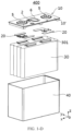
FIG. 1-B is a schematic structural diagram of a battery according to an embodiment of this application. -
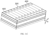
FIG. 1-C is a schematic structural diagram of a battery module according to an embodiment of this application. -
FIG. 1-D is a schematic structural diagram of a battery cell according to an embodiment of this application. -
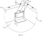
FIG. 2 is a schematic partial structural diagram of an interior of a box body applied to battery according to an embodiment of this application. -
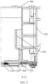
FIG. 3 is a schematic cross-sectional diagram of a direction A-A inFIG. 2 according to an embodiment of this application. -
FIG. 4 is a first schematic cross-sectional diagram of a one-way gravity valve according to an embodiment of this application. -
FIG. 5 is a second schematic cross-sectional diagram of a one-way gravity valve according to an embodiment of this application. -
FIG. 6 is an exploded view of a one-way gravity valve according to an embodiment of this application. -
FIG. 7 is a first local schematic diagram of a box body according to an embodiment of this application. -
FIG. 8 is a second local schematic diagram of a box body according to an embodiment of this application. -
FIG. 9 is a schematic structural diagram of a condensing part according to an embodiment of this application. -
FIG. 10 is a schematic structural diagram of another condensing part according to an embodiment of this application. -
FIG. 11 is a schematic structural diagram of still another condensing part according to an embodiment of this application. -
FIG. 12 is a schematic structural diagram of a pressure balance mechanism according to an embodiment of this application. -
FIG. 13 is a schematic structural diagram of a liquid storage member according to an embodiment of this application. -
FIG. 14 is a flowchart of a method for preparing battery according to an embodiment of this application. -
FIG. 15 is a block diagram of a device for preparing battery according to an embodiment of this application. - To make the objectives, technical solutions, and advantages of this application clearer and more comprehensible, the following further describes this application in detail with reference to the accompanying drawings and embodiments. It should be understood that the specific embodiments described herein are merely intended to explain this application, and are merely examples of embodiments of this application, but are not intended to limit the protection scope of this application. All equivalent changes made based on structures, shapes, and principles of this application shall fall within the protection scope of this application.
- Unless otherwise defined, all technical and scientific terms used herein shall have the same meanings as commonly understood by those skilled in the art to which this application belongs. The terms used in the specification of this application are merely intended to describe the specific embodiments but not intended to constitute any limitation on this application. The terms "include", "have" and any other variants in the specification, claims, and description of accompanying drawings of this application mean to cover the non-exclusive inclusion.
- The term "embodiment" described herein means that specific features, structures, or characteristics in combination with descriptions of the embodiments may be incorporated in at least one embodiment of this application. The word "embodiment" appearing in various locations in the specification does not necessarily mean a same embodiment, and is neither an independent or alternative embodiment mutually exclusive with other embodiments. Persons skilled in the art explicitly and implicitly understand that the embodiments described herein may combine with another embodiments.
- The term "and/or" in this specification describes only an association relationship for describing associated objects and represents that three relationships may exist. For example, A and/or B may represent the following three cases: A alone, both A and B, and B alone. In addition, the character "/" in this specification generally indicates that associated objects are in an "or" relationship.
- In addition, the terms "first", "second" and the like in the specification, claims or description of accompanying drawings of this application are used to distinguish between different objects but not describe a specific sequence, and can explicitly or implicitly include one or more features.
- In the descriptions of this application, unless otherwise specified, "a plurality of" means more than two (including two). Similarly, "a plurality of groups of' means more than two groups (including two groups).
- In the descriptions of this application, it should be noted that, unless otherwise specified and defined explicitly, the terms "mounting", "interconnection", and "connection" should be understood in a broad sense. For example, the "interconnection" or "connection" of a mechanical structure may be a physical connection. For example, the physical connection may be a fixed connection, for example, a fixed connection by using a fastener, such as a fixed connection by using a screw, a bolt, or another fastener; or the physical connection may be a detachable connection, such as a clamping or buckling connection; or the physical connection may be an integrated connection, for example, a connection through welding, bonding, or integral molding. The "interconnection" or "connection" of a circuit structure may be a physical connection, or may be an electrical connection or a signal connection. For example, the "interconnection" or "connection" of the circuit structure may be a direct connection, that is, a physical connection; or may be an indirect connection through at least one intermediate element, provided that the circuit is connected; or may be an internal connection between two elements. The signal connection may be a signal connection through a circuit, or may be a signal connection through a medium, such as a radio wave. Persons of ordinary skill in the art can understand specific meanings of these terms in this application based on specific situations.
- In order to clearly describe various orientations in the following embodiments, some orientation terms may be used, for example, a coordinate system shown in
FIG. 1-D defines orientations of the battery. A direction x represents a length direction of thebattery cell 400; a direction y is perpendicular to the direction x in a horizontal surface, and indicates a width direction of thebattery cell 400; a direction z is perpendicular to the direction x and the direction y, and indicates a height direction of the battery. In addition, the direction x, direction y, and direction z are intended to describe indication directions of operations and constructions of various components of the battery are not absolute but relative. Such indications are appropriate when the components of the battery are located at positions shown in the figures; however, when these positions change, such directions should be interpreted differently to reflect the changes. - Based on the same understanding of orientations, in the description of this application, the orientations or positional relationships indicated by the terms such as "center", "longitudinal", "lateral", "length", "width", "thickness", "up", "down", "front", "rear", "left", "right", "vertical", "horizontal", "top", "bottom", "inside", "outside", "clockwise", "counterclockwise", "axial", "radial", and "circumferential" are based on the orientations or positional relationships shown in the accompanying drawings, are merely intended to facilitate the descriptions of this application and simplify the descriptions, are not intended to indicate or imply that the apparatuses or components mentioned in this application must have specific orientations, or be constructed and operated for a specific orientation, and therefore shall not be construed as a limitation to this application.
- The rechargeable battery may be referred to as a secondary battery or a traction battery. Currently, widely used rechargeable batteries are lithium-ion batteries, for example, lithium-sulfur batteries, sodium lithium-ion batteries, or magnesium ion batteries, which are not limited thereto. For ease of description, the rechargeable battery herein may be collectively referred to as a battery.
- A safety property of the battery is an important property to evaluate the battery. Safety of the battery needs to be guaranteed to a maximum extent during use or charging.
- The battery is usually formed by connecting and combining a plurality of battery cells, and the battery cells experience temperature changes during use. In a case of an excessively high temperature, the battery cell needs to be cooled by using the thermal management component, to prevent the excessively high temperature of the battery cell from causing a failure, thermal runaway, and even an explosion of the battery cell.
- However, when the liquid in the thermal management component and other components cools the battery inside the box body through a pipe, because of a temperature difference between the liquid and gas inside the box body, a condensate is likely to be formed on a pipe wall. When a large amount of condensate and the battery coexist in the same box body, safety problems such as a short circuit are prone to occur, seriously affecting service life of the battery. In order to resolve the foregoing problem, the inventor coated a conductive member in the box body with an insulation material to prevent the conductive member from coming in contact with the condensate to cause a short circuit. However, the inventor found that such coating was difficult to completely cover the conductive member; in addition, such coating was more difficult for irregular-shaped conductive members. Based on this, the inventor attempted to discharge excessive condensates condensed by the thermal management component of the box body out of the box body, so as to resolve safety problems such as short circuits.
- In view of this, this application provides a box body applied to battery, so as to discharge a condensate out of the battery and prevent a large amount of condensate from accumulating inside the battery for a long time to cause potential safety hazards. For the box body applied to battery in this application, the condensate can be discharged out of the battery in a timely manner, and the condensate outside the pipe wall of the pipe connected to the thermal management component can also be located in a position convenient for discharging, thereby further reducing impact of the condensate on the battery, for example, reducing a risk of short circuits of the battery cell caused by excessive condensate.
- The battery in this embodiment of this application can be applied to various electric apparatuses capable of using electrical energy as a power source. The electric apparatus herein may be, but not limited to, an electric vehicle, an electric train, an electric bicycle, a golf cart, a ship, a drone, or the like. In addition, the electric apparatus may be an apparatus that uses only the battery as a power source, or may be a hybrid electric apparatus. The battery provides electrical energy for the electric apparatus, and drives the electric apparatus to travel through the motor.
- For example,
FIG. 1-A is a schematic structural diagram of an electric apparatus according to an embodiment of this application. The electric apparatus may be a vehicle, and the vehicle may be an oil-fueled vehicle, a gas-fueled vehicle, or a new energy vehicle. The new energy vehicle may be a battery electric vehicle, a hybrid electric vehicle, an extended-range vehicle, or the like. The vehicle includes abattery 200, acontroller 210, and amotor 220. Thebattery 200 is configured to supply power to thecontroller 210 and themotor 220 as an operating power source and a driving power source of the vehicle. For example, thebattery 200 is configured to meet an operating power requirement of the vehicle during startup, navigation, and operating. For example, thebattery 200 supplies power to thecontroller 210, and thecontroller 210 controls thebattery 200 to supply power to themotor 220. Themotor 220 receives and uses the power of thebattery 200 as a driving power source for the vehicle, to replace or partially replace fuel or natural gas to provide driving power for the vehicle. - In order to make the battery provide higher functions to meet usage requirements, the
battery 200 may include a plurality of battery modules electrically connected to each other. As shown inFIG. 1-B , thebattery 200 includes afirst box body 201, asecond box body 202, and a plurality ofbattery modules 300. Thefirst box body 201 and thesecond box body 202 are fastened together, and the plurality ofbattery modules 300 are arranged in a space enclosed by thefirst box body 201 and thesecond box body 202. In some embodiments, thefirst box body 201 and thesecond box body 202 are connected in a sealed manner. - As shown in
FIG. 1-C , thebattery module 300 includes a plurality ofbattery cells 400, and the plurality ofbattery cells 400 may be electrically connected in a series, parallel, or hybrid manner to implement a larger current or voltage. The hybrid connection refers to a combination of series connection and parallel connection. For example, as shown inFIG. 1-C , thebattery cell 400 may be placed vertically, a height direction of thebattery cell 400 is consistent with the direction z, a length direction of thebattery cell 400 is consistent with the direction x, and a plurality ofbattery cells 400 is arranged side by side along a width direction in the direction y. Alternatively, thebattery cell 400 may be laid flat, the width direction of thebattery cell 400 is consistent with the direction z, the length direction of thebattery cell 400 is consistent with the direction x, and the plurality ofbattery cells 400 are stacked for at least one layer along the direction z. Each layer includes a plurality ofbattery cells 400 spaced apart along the direction x. - In order to make those skilled in the art clearly understand the improvements to this application, an overall structure of the
battery cell 400 is first described. - As shown in
FIG. 1-D , thebattery cell 400 includes ahousing body 40, anelectrode assembly 30, and anend cover assembly 10. Theend cover assembly 10 includes an end cover plate 10', and the end cover plate 10' is connected (for example, being welded) to thehousing body 40, to form a housing of thebattery cell 400. Theelectrode assembly 30 is disposed in thehousing body 40, and thehousing body 40 is filled with electrolyte. Thebattery cell 400 may be of a cubic shape, a rectangular shape, or a cylindrical shape. - One or
more electrode assemblies 30 may be provided based on an actual use requirement. As shown inFIG. 1-D , at least two independently woundelectrode assemblies 30 may alternatively be provided in the battery. A body portion of theelectrode assembly 30 may be formed by winding or stacking a first electrode plate, a second electrode plate, and a separator located between the first electrode plate and the second electrode plate that are adjacent, where the separator is an insulator between the first electrode plate and the second electrode plate that are adjacent. In this embodiment, the first electrode plate being a positive electrode plate and the second electrode plate being a negative electrode plate are used as an example for description. A positive active material is applied on a coated region of the positive electrode plate, and a negative active material is applied on a coated region of the negative electrode plate. A plurality of uncoated regions extending from the coated regions of the body portion are stacked to form a tab. Theelectrode assembly 30 includes twotabs 301, namely a positive tab and a negative tab. The positive tab extends from the coated region of the positive electrode plate, and the negative tab extends from the coated region of the negative electrode plate. - The
end cover assembly 10 is disposed on the top of theelectrode assembly 30. As shown inFIG. 1-D , theend cover assembly 10 includes an end cover plate 10' and twoelectrode terminals 5, and the twoelectrode terminals 5 are a positive terminal and a negative terminal. Eachelectrode terminal 5 is correspondingly provided with a connectingmember 20, and the connectingmember 20 is located between the end cover plate 10' and theelectrode assembly 30. - For example, in
FIG. 1-D , thetab 301 of theelectrode assembly 30 is located at the top, the positive tab is connected to the positive terminal through one connectingmember 20, and the negative tab is connected to the negative terminal through the other connectingmember 20. Optionally, thebattery cell 400 may include twoend cover assemblies 10, respectively disposed at two ends of thehousing body 40, and eachend cover assembly 10 is provided with oneelectrode terminal 5. - The end cover plate 10' may be further provided with an explosion-proof member to release gas out of the
battery cell 400 in a timely manner in a case of too much gas in thebattery cell 400, thereby avoiding explosion. - The end cover plate 10' is provided with a degassing hole, and the degassing hole may be provided at a middle position of the end cover plate 10' in the length direction. The explosion-proof member includes a
pressure relief mechanism 6, and thepressure relief mechanism 6 is disposed in the degassing hole. In a normal state, thepressure relief mechanism 6 is installed in the degassing hole in a sealed manner. Thepressure relief mechanism 6 is actuated to be open when thebattery cell 400 swells to increase an air pressure in the housing to exceed a preset value, and the gas is released outward through thepressure relief mechanism 6. - The
pressure relief mechanism 6 is an element or a component that can be actuated to release internal pressure and/or internal substances when the internal pressure or internal temperature of thebattery cell 400 reaches a predetermined threshold. Thepressure relief mechanism 6 may be specifically in a form of an explosion-proof valve, a gas valve, a pressure relief valve, a safety valve, or the like, and may specifically use a pressure-sensitive or temperature-sensitive element or structure. That is, when the internal pressure or temperature of thebattery cell 400 reaches the predetermined threshold, thepressure relief mechanism 6 performs an action or a weak structure provided in thepressure relief mechanism 6 is damaged, to form an opening or a channel for releasing the internal pressure. The threshold described in this application may be a pressure threshold or a temperature threshold. Design of the threshold varies with different design requirements, for example, the threshold may be designed or determined based on an internal pressure value or internal temperature value that is considered to be dangerous or out of control for thebattery cell 400. In addition, the threshold may depend on a material of one or more of the positive electrode plate, the negative electrode plate, the electrolyte, and the separator in thebattery cell 400. - "Actuate" described in this application means that the
pressure relief mechanism 6 performs an action or is activated to a specific state, so that the internal pressure of thebattery cell 400 can be relieved. The action performed by thepressure relief mechanism 6 may include but is not limited to: cracking, breaking, tearing, or opening at least part of thepressure relief mechanism 6, or the like. When thepressure relief mechanism 6 is actuated, high-pressure and high-temperature substances inside thebattery cell 400 are released from an actuated part as emissions. In this way, thebattery cell 400 discharges its pressure under a condition of controllable pressure or temperature, thereby avoiding more serious potential accidents. The emissions from thebattery cell 400 described in this application include but are not limited to: electrolyte, fragments of positive and negative electrode plates and separator because of dissolution or breaking, high-temperature and high-pressure gas and flames generated by reactions, and the like. The high-temperature and high-pressure emissions are released toward a side of thebattery cell 400 at which thepressure relief mechanism 6 is disposed, and may be more specifically released toward a region for actuation of thepressure relief mechanism 6. The strength and destructive power of such emissions are probably great, even great enough to break one or more structures in that direction. - In some embodiments, as shown in
FIG. 1-D , the end cover plate 10' is provided with a through hole for injecting the electrolyte into thebattery cell 400. The through hole may be a round hole, an elliptical hole, a polygonal hole, or holes of other shapes, and may extend along the height direction of the end cover plate 10'. Theend cover plate 10 is provided with an injection member 2 for closing the through hole. - As shown in
FIG. 2 andFIG. 3 , abox body 500 applied tobattery 200 provided in this embodiment of this application includes a carryingplate 510 and a one-way gravity valve 520. The carryingplate 510 is mainly configured to carry thebattery 200, and the one-way gravity valve 520 is provided on the carryingplate 510, and is configured to be closed when a gravity of liquid in thebox body 500 is less than a threshold; and to be open when the gravity of the liquid in thebox body 500 reaches the threshold, so as to discharge the liquid through the one-way gravity valve 520. - The
box body 500 provided by this embodiment of this application is provide with the one-way gravity valve 520. When there is excessive liquid in the box body, for example, when the gravity of the liquid reaches the threshold, the liquid in thebox body 500 can be discharged in a timely manner, so as to avoid holding up excessive liquid in thebox body 500 for a long time, thereby reducing potential safety hazards and improving service life of thebattery 200. - It should be noted that, in addition to the condensate generated on the outer wall of the pipe connected to the thermal management component, the liquid in the
box body 500 includes emissions released during actuation of thepressure relief mechanism 6 of thebattery cell 400, and so on. The condensate and the emissions are likely to hold up in thebox body 500, further affecting service life of thebattery 200 and even resulting in safety hazards. In this embodiment of this application, the one-way gravity valve 520 provided in the box body can discharge the liquid out of thebox body 500 in a time manner, to avoiding the liquid from being held up in thebox body 500 for a long time, and further improving the service life and use safety of thebattery 200. - In this embodiment of this application, the carrying
plate 510 for carrying thebattery 200 is usually disposed at the bottom of thebox body 500. Therefore, the one-way gravity valve 520 disposed on the carryingplate 510 is also disposed at the bottom of thebox body 500, helping discharge the liquid out of thebox body 500. - As shown in
FIG. 2 andFIG. 3 , in this embodiment of this application, the one-way gravity valve 520 may be disposed close to a side wall of thebox body 500. The side wall is provided with a via hole through which the pipe connected to the thermal management component passes. The outer wall of the pipe near the via hole is more likely to produce a condensate. Therefore, the one-way gravity valve 520 is disposed in a position near the via hole, facilitating discharge of the condensate. - In a practical application, a value of the threshold may be set based on actual needs, and a structure and size of the one-
way gravity valve 520 may be determined based on the value of the threshold, so as to meet needs of discharging the liquid out of thebox body 500. This is not particularly limited in this embodiment of this application. - It should be noted that the structure for liquid discharging in this embodiment of this application is the one-
way gravity valve 520 related to gravity, and therefore the threshold is also a gravity-related value. - It should also be noted that, in addition to the one-
way gravity valve 520 provided in this embodiment of this application for discharging the liquid, other structures may alternatively be used for discharging the liquid out of thebox body 500, and any structure facilitating discharging of the liquid out of thebox body 500 should fall within the protection scope of the embodiments of this application. - As shown in
FIG. 4 and FIG. 5 , in an example, in this embodiment of this application, the device in use is the one-way gravity valve 520, and the one-way gravity valve 520 includes aliquid discharge member 521 and amovable assembly 522. Theliquid discharge member 521 has a first throughhole 523, and theliquid discharge member 521 is configured to discharge the liquid such as the condensate and emissions through the first throughhole 523 when the gravity of the liquid in thebox body 500 reaches the threshold. Themovable assembly 522 is installed on theliquid discharge member 521 and capable of moving relative to the first throughhole 523, so that themovable assembly 522 seals the first throughhole 523 when the gravity of the liquid in thebox body 500 is less than the threshold, and opens the first throughhole 523 when the gravity of the liquid in thebox body 500 reaches the threshold. -
FIG. 4 shows a case that themovable assembly 522 seals the first throughhole 523 when the gravity of the liquid in thebox body 500 is less than the threshold, so as to play a role of sealing thebox body 500 when there is a small amount of liquid or no liquid in thebox body 500.FIG. 5 shows a case that themovable assembly 522 opens the first throughhole 523 when the gravity of the liquid in thebox body 500 reaches the threshold, so as to open the first throughhole 523 to discharge the liquid when there is a large amount of liquid needing to be discharged out of thebox body 500. This avoids holding up the liquid in thebox body 500 for a long time to affect normal use of thebattery 200. - In a practical application, there may be various specific positions for disposing the
movable assembly 522. For example, themovable assembly 522 may be disposed at the bottom of the first throughhole 523, or may be disposed on the side wall of the first throughhole 523, which is not particularly limited in this embodiment of this application. - In this embodiment of this application, further referring to
FIG. 4 and FIG. 5 , theliquid discharge member 521 may have anaccommodating chamber 524, and themovable assembly 522 may be disposed in theaccommodating chamber 524 and is capable of moving up and down in theaccommodating chamber 524. Themovable assembly 522 moves up and down in theaccommodating chamber 524 to seal or open the first throughhole 523. - In a practical application, because the
movable assembly 522 needs to seal and open the first throughhole 523 inside theaccommodating chamber 524, theaccommodating chamber 524 needs to communicate with the first throughhole 523, so that the liquid flowing into the first throughhole 523 can flow through theaccommodating chamber 524 to facilitate liquid discharge. - In a practical application, the
accommodating chamber 524 may be provided at the bottom of the first throughhole 523, or may be provided at the middle of the first throughhole 523, with a central axis of theaccommodating chamber 524 aligned with a central axis of the first throughhole 523, thereby facilitating centering of themovable assembly 522 and the first throughhole 523 to achieve a better sealing effect. - In a practical application, the
movable assembly 522 may be in various structural forms provided that the first throughhole 523 can be sealed or opened movably under the action of gravity, which is not particularly limited in this embodiment of this application. - As shown in
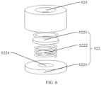
FIG. 6 , in this embodiment of this application, themovable assembly 522 further includes a sealingmember 5221 and anelastic member 5222. The sealingmember 5221 is movably connected to theaccommodating chamber 524 to seal or open the first throughhole 523. Theelastic member 5222 is configured to provide a preset supporting force to the sealingmember 5221, and the preset supporting force is the same as the threshold, so that the sealingmember 5221 can seal the first throughhole 523 when the gravity of the liquid in thebox body 500 is less than the preset supporting force, and open the first throughhole 523 when the gravity of the liquid in thebox body 500 reaches the preset supporting force, to discharge the liquid. - In this embodiment of this application, in a simple connection manner, the sealing
member 5221 may be directly connected to theelastic member 5222, and theelastic member 5222 directly supports the sealingmember 5221 to provide the preset supporting force to the sealingmember 5221. - In a practical application, the sealing
member 5221 may be a structural member such as a sealing gasket whose cross-sectional area is larger than a cross-sectional area of the first throughhole 523. Theelastic member 5222 may be a spring, and an upper end of the spring is connected to the sealingmember 5221, and a lower end of the spring is supported on aspring base 5223. Thespring base 5223 can play a role of fixing and limiting the lower end of the spring, preventing the spring from being twisted in an extension and contraction process and affecting alignment of the sealingmember 5221 and the first throughhole 523, and reducing impact on the sealing effect. In addition, a second throughhole 5224 needs to be further provided on thespring base 5223, so that the liquid flowing into theaccommodating chamber 524 can be discharged from the second throughhole 5224. - The
box body 500 provided in this embodiment of this application further includes a bottom plate 530. The bottom plate 530 is configured to connect to the carryingplate 510 to form a water storage chamber. The water storage chamber communicates with the first throughhole 523, so as to collect the liquid discharged from the first throughhole 523, thereby preventing the liquid out of thebox body 500 from directly flowing to the electric apparatus using thebattery 200 to cause safety hazards. - In a practical application, the bottom plate 530 may be detachably connected to the carrying
plate 510. When the liquid in the water storage chamber reaches a specific amount, the bottom plate 530 may be disassembled to discharge the liquid out of the water storage chamber. Alternatively, a liquid discharge opening may be provided in the bottom plate 530, and the liquid discharge opening is sealed by using a detachable sealing plug, so as to open the sealing plug when necessary to discharge the liquid out of the water storage chamber. - As shown in
FIG. 2 , in this embodiment of this application, thebox body 500 further includes afirst wall 540. Thefirst wall 540 is configured to connect to the carryingplate 510 to form an accommodating chamber for accommodating thebattery 200, thefirst wall 540 is provided with aliquid discharge hole 5403, and theliquid discharge hole 5403 is configured to discharge liquid exceeding a height of theliquid discharge hole 5403 when a height of a liquid surface of the liquid in thebox body 500 in a direction of gravity is greater than or equal to that of theliquid discharge hole 5403. This avoids a case that only the one-way gravity valve 520 cannot meet a requirement of timely and rapid liquid discharge when there is excessive liquid in thebox body 500, so as to ensure that the liquid in thebox body 500 can be discharged in a timely manner. - In a practical application, a position for providing the
liquid discharge hole 5403 may be set based on an actual situation, for example, theliquid discharge hole 5403 is provided at a position of thefirst wall 540 close to the carryingplate 510, which is not particularly limited in this embodiment of this application. In addition, a shape of theliquid discharge hole 5403 may be circular, elliptical, semicircular, or the like. A size of theliquid discharge hole 5403 may be determined based on a size of thebox body 500, which is not particularly limited in this embodiment of this application. -
FIG. 7 is a schematic structural diagram of theliquid discharge hole 5403 on thefirst wall 540. In this embodiment of this application, thefirst wall 540 includes a first sub-wall 5401 and a second sub-wall 5402, and a hollow chamber is formed between the first sub-wall 5401 and thesecond sub-wall 5402. The first sub-wall 5401 is an inner wall of thebox body 500, and the second sub-wall 5402 is an outer wall of thebox body 500. The first sub-wall 5401 is provided with theliquid discharge hole 5403, that is, theliquid discharge hole 5403 penetrates through only thefirst sub-wall 5401 of thefirst wall 540, so that the liquid whose height of the liquid surface in the direction of gravity is greater than or equal to that of theliquid discharge hole 5403 is collected in the hollow chamber and the liquid in thebox body 500 can be discharged in a timely manner. - As shown in
FIG. 8 , thefirst wall 540 further includes avent hole 5404, and thevent hole 5404 is configured to communicate with the inside and the outside of thebox body 500. In a practical application, theliquid discharge hole 5403 may be part of thevent hole 5404, so as to function as a vent while discharging the fluid. - As shown in
FIG. 2 , in this embodiment of this application, thebox body 500 further includes a condensingpart 550. The condensingpart 550 may be configured to block the vent hole 5404 (that is, block the position in which theliquid discharge hole 5403 is located), so as to condense gas that flows into thebox body 500 through thevent hole 5404. The condensingpart 550 may condense the gas flowing into thebox body 500 in advance, so that the condensed liquid can be collected in a specified position. In this way, condensed liquid resulting from condensing of gas dispersed into thebox body 500 can be prevented from flowing into different positions of thebox body 500, implementing collection of the condensate and facilitating discharge of the condensate. - In this embodiment of this application, the condensing
part 550 is disposed on the inner surface of thebox body 500 at a position opposite thevent hole 5404, so that gas flowing from thevent hole 5404 first comes in contact with the condensingpart 550, to achieve a purpose of preventing the gas from condensing in the box body and then coming in contact with conductive members inside the box body. - In a practical application, as shown in
FIG. 3 , thebox body 500 further includes a thermal management component 560. The thermal management component 560 is configured to adjust a temperature of thebattery 200. The thermal management component 560 intersects thefirst wall 540 to enter thebox body 500 through thefirst wall 540, thereby implementing temperature adjustment for thebattery 200. The thermal management component 560 may be a component such as a water cooling plate, which is not particularly limited in this embodiment of this application. - Further referring to
FIG. 3 , in this embodiment of this application, a first portion of the condensingpart 550 extends along the thermal management component 560, so as to be attached to the thermal management component 560, so that the condensingpart 550 can conduct heat with the thermal management component 560 and the condensingpart 550 has a good condensing effect. A second portion of the condensingpart 550 extends along thefirst wall 540 to block thevent hole 5404, so that the condensate resulting from condensing of the gas entering from thevent hole 5404 is also collected in the condensingpart 550, thereby preventing the condensate from flowing to other positions of thebox body 500 and facilitating discharge of the condensate. - In a practical application, the condensing
part 550 may be in various structural forms. In this embodiment of this application, the condensingpart 550 may be a cover-like structure, and the cover-like structure may block thevent hole 5404, so that gas entering from thevent hole 5404 can come in contact with the cover-like structure and be condensed on the cover-like structure. The resulting condensate flows along the cover-like structure and is collected in the condensingpart 550 along the cover-like structure. - In this embodiment of this application, a space enclosed by the condensing
part 550 and thebox body 500 communicates with the first throughhole 523 of the one-way gravity valve 520, so that the condensate collected in the condensingpart 550 can flow to the one-way gravity valve 520, and is discharged from the first throughhole 523 when the gravity of the liquid reaches the threshold. - Further referring to
FIG. 2 andFIG. 8 , the condensingpart 550 with a cover-like structure is attached to a surrounding region of thevent hole 5404 on thefirst wall 540, and is provided with afirst opening 5501 through which gas flows into thebox body 500. The gas condensed in the cover-like structure may enter thebox body 500 through thefirst opening 5501. Because the gas has already been condensed once, a probability of re-condensing of the gas entering thebox body 500 is reduced. Even if the gas is re-condensed, the resulting condensate may not be excessive to bring safety hazards. - In this embodiment of this application, the
first opening 5501 is provided in a first direction of the cover-like structure, and the first direction is a direction opposite the direction of gravity. - In a practical application, in order to prevent greater harm caused by high-temperature and high-pressure emissions discharged out of the
battery cell 400 during thermal runaway of thebattery cell 400, a fire prevention system is usually provided inside thebox body 500, to implement fire prevention for thebattery cell 400. - In this embodiment of this application, the position of the
first opening 5501 may be opposite a joint of the pipe of the fire prevention system. Thefirst opening 5501 can collect fluid leaked from the joint of the pipe of the fire prevention system in a case of fluid leakage at the joint of the pipe of the fire prevention system, so as to prevent the fluid leaked at the joint of the pipe of the fire prevention system from flowing into thebox body 500 to affect thebattery 200. - In a practical application, a size of the
first opening 5501 may be set to be larger, so as to able to catch the fluid leaked from the joint of the pipe of the fire-fighting system, and a specific size is not limited in this embodiment of this application. - In a practical application, a projection surface of the cover-like structure on the
first wall 540 may be of various shapes, for example, a rectangular surface as shown inFIG. 9 , a U-shaped surface as shown inFIG. 10 , and a V-shaped surface as shown inFIG. 11 , which is not particularly limited in this embodiment of this application. In addition, the specific size of the cover-like structure may be determined based on an actual size of an accommodating space of thebox body 500, which is not particularly limited in this embodiment of this application. - As shown in
FIG. 9 to FIG. 11 , the cover-like structure of the condensingpart 550 is further provided with aflow channel 5502, and theflow channel 5502 is configured to guide the condensate of the cover-like structure to the one-way gravity valve 520. Portions of the condensingpart 550 on two sides of theflow channel 5502 are attached to thefirst wall 540. - In a practical application, attaching described above may be in various connection manners such as welding or gluing, which is not limited in this embodiment of this application.
- In this embodiment of this application, the cover-like structure has a
second opening 5503 corresponding to theflow channel 5502, and thesecond opening 5503 is configured to guide the condensate on the cover-like structure to theflow channel 5502 and then into the one-way gravity valve 520 through theflow channel 5502. The one-way gravity valve 520 is further configured to discharge the condensate out of thebox body 500 from theflow channel 5502 when a gravity of the condensate in theflow channel 5502 reaches the threshold. Thesecond opening 5503 is provided in a second direction of the cover-like structure, and the second direction is the direction of gravity. - In a practical application, the
flow channel 5502 may be designed as a thin strip to increase a height of the flow channel and further increase pressure of the liquid, thereby ensuring that the liquid in the flow channel can reach the threshold of the one-way gravity valve 520 and the one-way gravity valve can be open in a timely manner. - As shown in
FIG. 12 , thebox body 500 further includes apressure balance mechanism 570, and thepressure balance mechanism 570 is configured to balance the pressure inside and outside thebox body 500. In a practical application, thepressure balance mechanism 570 may be installed in thevent hole 5404 of the box body, and gas outside thebox body 500 can flow into thebox body 500 through thepressure balance mechanism 570. - As shown in
FIG. 13 , in this embodiment of this application, thebox body 500 further includes aliquid storage member 580 disposed on the inner surface of thebox body 500, and theliquid storage member 580 is configured to, when the height of the liquid surface of the liquid in thebox body 500 in the direction of gravity reaches a height of theliquid storage member 580, store liquid that flows into theliquid storage member 580, and discharge the liquid flowing into theliquid storage member 580 to the one-way gravity valve 520. - In a practical application, the
liquid storage member 580 includes a height-limitingplate 5801 and aguiding plate 5802. The height-limitingplate 5801 comes in contact with the inner surface of the first sub-wall 5401, and the height-limitingplate 5801 and the first sub-wall 5401 form a liquid height-limitingcavity 5803 with an opening on the top in the direction of gravity. The liquid height-limitingcavity 5803 is configured to allow flowing of the liquid when a surface of the liquid is higher than the liquid height-limitingcavity 5803 in the direction of gravity. The guidingplate 5802 comes in contact with a surface of the carryingplate 510 facing toward thebattery cell 400, and a guiding channel is provided between the guidingplate 5802 and the carryingplate 510. Two ends of the guiding channel communicate with the liquid height-limitingcavity 5803 and the one-way gravity valve 520 respectively. The guiding channel is configured to discharge the liquid from the liquid height-limitingcavity 5803 to the one-way gravity valve 520. - In another aspect, this application further provides a battery. The
battery 200 includes the foregoingbox body 500, and thebox body 500 is configured to accommodate thebattery 200. The specific structural form and working principle of thebox body 500 have been described in detail in the foregoing embodiment, and details are not repeated in this embodiment. - To sum up, the battery in this embodiment of this application is provided with the box body, and the box body is provided with the one-way gravity valve. A time for discharging the liquid in the box body is determined based on the threshold of the one-way gravity valve. When there is excessive liquid in the box body, the liquid in the box body can be discharged in a timely manner, thereby reducing safety hazards and improving service life of the battery. When there is a relatively small amount of liquid in the box body that is not enough to open the one-way gravity valve, the small amount of liquid in the box body can play a role of cooling the battery inside the box body under the premise of not affecting safety performance of the battery.
- In another aspect, this application further provides an electric apparatus. The electric apparatus includes the
battery 200 described above, and thebattery 200 is configured to supply electrical energy. Thebattery 200 is disposed in thebox body 500, and thebox body 500 can discharge the liquid outside in a timely, so as to prevent the liquid from being held up in thebox body 500 for a long time and cause potential safety hazard. The specific structural form and working principle of thebox body 500 have been described in detail in the foregoing embodiment, and details are not repeated in this embodiment. - The foregoing describes the battery and the electric apparatus in the embodiments of this application; and the following describes a method and device for preparing battery in the embodiments of this application. For those not described in detail, refer to the foregoing embodiments.
- In another aspect, an embodiment of this application further provides a method for preparing battery. As shown in
FIG. 14 , the method for preparing battery may include the following steps. - Step S1410: Install a battery on a carrying plate.
- Step S1420: Dispose a one-way gravity valve on the carrying plate, where the one-way gravity valve is configured to be closed when a gravity of liquid in the box body is less than a threshold, and to be open when the gravity of the liquid in the box body reaches the threshold, so as to discharge the liquid through the one-way gravity valve.
- With reference to the embodiment of the
box body 500, it can be learned that thebattery 200 is disposed in thebox body 500. When there is a relatively large amount of liquid in thebox body 500, the liquid can be discharged through the one-way gravity valve 520 disposed in thebox body 500, thereby reducing potential safety hazards and improving service life of thebattery 200. - With reference to the embodiment of the
box body 500, it can be learned that thebox body 500 further includes other components, and the components can be manufactured by using a corresponding method to finally obtain thebox body 500 as required that is convenient for liquid discharge. In a practical application, any methods for manufacturing related components and connecting related components fall within the protection scope of the embodiments of this application, and details are not described in the embodiments of this application. - In another aspect, an embodiment of this application further provides a device for preparing battery. Referring to
FIG. 15, FIG. 15 is a block diagram of a device for manufacturing battery according to an embodiment of this application. As shown inFIG. 15 , thedevice 1500 for preparing battery may include: a first apparatus 1510 and asecond apparatus 1520. - The first apparatus 1510 may be configured to install a battery on a carrying plate, where the carrying plate is part of a box body and is disposed at the bottom of the box body.
- The
second apparatus 1520 may be configured to dispose a one-way gravity valve on the carrying plate. - The one-way gravity valve is configured to be closed when a gravity of liquid in the box body is less than a threshold, and to be open when the gravity of the liquid in the box body reaches the threshold, so as to discharge the liquid through the one-way gravity valve.
- Specific details of the devices for preparing battery have been described in detail in the corresponding embodiment of the box body used for the battery, and details are not repeated herein.
- The foregoing protection subjects of this application and the features in the embodiments may be referenced to each other. Those skilled in the art can also flexibly combine the technical features in the different embodiments to form more embodiments if the structure permits.
- The battery, the electric apparatus, and the method and device for manufacturing the battery provided by this application are described in detail above. Specific embodiments are used in this specification to describe the principles and implementations of this application, and the descriptions of the foregoing embodiments are merely intended to help understand the method and core ideas of this application. It should be noted that those of ordinary skill in the art may further make several improvements and modifications to this application without departing from the principles of this application, and these improvements and modifications also fall within the protection scope of the claims of this application.
Claims (12)
- A box body (500) for housing a battery, comprising:a carrying plate (510), configured to carry a battery (200);a one-way gravity valve (520), disposed on the carrying plate (510); whereinthe one-way gravity valve (520) is configured to be closed when a gravity of liquid in the box body (500) is less than a threshold, and to be open when the gravity of the liquid in the box body (500) reaches the threshold, so as to discharge the liquid through the one-way gravity valve (520); anda liquid storage member (580) disposed on the inner surface of the box body (500), and the liquid storage member (580) is configured to, when the height of a liquid surface of the liquid in the box body (500) in the direction of gravity reaches a height of the liquid storage member (580), store liquid that flows into the liquid storage member (580), and discharge the liquid flowing into the liquid storage member (580) to the one-way gravity valve (520);wherein the threshold is reached when the height of the liquid surface of the liquid in the box body (500) in the direction of gravity reaches the height of the liquid storage member (580);, wherein the one-way gravity valve (520) comprises:a liquid discharge member (521), provided with a first through hole (523), wherein the liquid discharge member (521) is configured to discharge the liquid through the first through hole (523) when the gravity of the liquid in the box body (500) reaches the threshold; anda movable assembly (522), installed on the liquid discharge member (521) and capable of moving relative to the first through hole (523), so that the movable assembly (522) seals the first through hole (523) when the gravity of the liquid in the box body (500) is less than the threshold, and opens the first through hole (523) when the gravity of the liquid in the box body (500) reaches the threshold, and further comprising a bottom plate (530), configured to connect to the carrying plate (510) to form a water storage chamber, wherein the water storage chamber communicates with the first through hole (523), so as to collect the liquid discharged from the first through hole (523);the box body (500) further comprising a first wall (540), configured to connect to the carrying plate (510) to form an accommodating chamber (524) for accommodating the battery (200), wherein the first wall (540) is provided with a liquid discharge hole (5403), and the liquid discharge hole (5403) is configured to discharge liquid exceeding a height of the liquid discharge hole (5403) when a height of a liquid surface of the liquid in the box body (500) in a direction of gravity is greater than or equal to that of the liquid discharge hole (5403); andwherein the first wall (540) further comprises a vent hole (5404), and the vent hole (5404) is configured to communicate with the inside and the outside of the box body (500); and the box body (500) further comprises a condensing part (550) configured to block the vent hole (5404), so as to condense gas flowing into the box body (500) through the vent hole (5404).
- The box body (500) according to claim 1, wherein the first wall (540) comprises a first sub-wall (5401) and a second sub-wall (5402), a hollow chamber is formed between the first sub-wall (5401) and the second sub-wall (5402), the first sub-wall (5401) is an inner wall of the box body (500), the second sub-wall (5402) is an outer wall of the box body (500), and the first sub-wall (5401) is provided with the liquid discharge hole (5403), so that the liquid whose height of the liquid surface in the direction of gravity is greater than or equal to that of the liquid discharge hole (5403) is collected in the hollow chamber.
- The box body (500) according to claim 1 or 2, wherein the condensing part (550) is provided on an inner surface of the box body (500).
- The box body (500) according to any preceding claim, wherein the box body (500) further comprises a thermal management component (560), the thermal management component (560) is configured to adjust a temperature of the battery (200), the thermal management component (560) intersects the first wall (540), a first portion of the condensing part (550) extends along the thermal management component (560), so as to be attached to the thermal management component (560), and a second portion of the condensing part (550) extends along the first wall (540) to block the vent hole (5404).
- The box body (500) according to any preceding claim, wherein the condensing part (550) comprises a cover-like structure, and the cover-like structure blocks the vent hole (5404), the cover-like structure is preferably attached to a surrounding region of the vent hole (5404) on the first wall (540) and is provided with a first opening (5501) through which gas flows into the box body (500), more preferably the first opening (5501) is provided in a first direction of the cover-like structure and the first direction is a direction opposite the direction of gravity, and still more preferably the first opening is further configured to collect fluid leaked from a pipe joint of a fire prevention system in a case of fluid leakage at the joint.
- The box body (500) according to claim 5, wherein the condensing part (550) further comprises a flow channel (5502), and the flow channel (5502) is configured to guide a condensate on the cover-like structure to the one-way gravity valve (520), and preferably wherein portions of the condensing part (550) on two sides of the flow channel (5502) are attached to the first wall (540).
- The box body (500) according to claim 6, wherein the cover-like structure is provided with a second opening (5503) corresponding to the flow channel (5502), and the second opening (5503) is configured to guide the condensate on the cover-like structure to the flow channel (5502), and preferably wherein the second opening (5503) is provided in a second direction of the cover-like structure, and the second direction is the direction of gravity.
- The box body (500) according to any preceding claim, wherein the box body (500) further comprises:
a pressure balance mechanism (570), configured to balance pressure inside and outside the box body (500), and preferably wherein the pressure balance mechanism (570) is provided on the second sub-wall (5402), and gas flowing from outside the box body (500) to the hollow chamber through the pressure balance mechanism (570) flows into the box body (500) through the vent hole (5404). - A battery (200), comprising the box body (500) according to any one of claims 1 to 8, wherein the box body (500) is configured to accommodate the battery (200).
- An electric apparatus, comprising the battery (200) according to claim 9, wherein the battery (200) is configured to supply electrical energy.
- A method for preparing battery, comprising:installing a battery (200) on a carrying plate (510) of a box body (500) according to any of claims 1 to 8; anddisposing a one-way gravity valve (520) on the carrying plate (510); whereinthe one-way gravity valve (520) is configured to be closed when a gravity of liquid in the box body (500) is less than a threshold, and to be open when the gravity of the liquid in the box body (500) reaches the threshold, so as to discharge the liquid through the one-way gravity valve (520).
- A device (1500) for preparing battery, comprising:a first apparatus (1501), configured to install a battery (200) on a carrying plate (510) of a box body (500) according to any of claims 1 to 8; anda second apparatus (1502), configured to dispose a one-way gravity valve (520) on the carrying plate (510); whereinthe one-way gravity valve (520) is configured to be closed when a gravity of liquid in the box body (500) is less than a threshold, and to be open when the gravity of the liquid in the box body (500) reaches the threshold, so as to discharge the liquid through the one-way gravity valve (520).
Priority Applications (1)
| Application Number | Priority Date | Filing Date | Title |
|---|---|---|---|
| HUE20957976A HUE068408T2 (en) | 2020-10-19 | 2020-10-19 | Box body for battery, battery, electric apparatus, and battery manufacturing method and device |
Applications Claiming Priority (1)
| Application Number | Priority Date | Filing Date | Title |
|---|---|---|---|
| PCT/CN2020/121996 WO2022082393A1 (en) | 2020-10-19 | 2020-10-19 | Box body for battery, battery, electric apparatus, and battery manufacturing method and device |
Publications (4)
| Publication Number | Publication Date |
|---|---|
| EP4064449A1 EP4064449A1 (en) | 2022-09-28 |
| EP4064449A4 EP4064449A4 (en) | 2023-09-27 |
| EP4064449B1 true EP4064449B1 (en) | 2024-07-10 |
| EP4064449C0 EP4064449C0 (en) | 2024-07-10 |
Family
ID=81289524
Family Applications (1)
| Application Number | Title | Priority Date | Filing Date |
|---|---|---|---|
| EP20957976.2A Active EP4064449B1 (en) | 2020-10-19 | 2020-10-19 | Box body for battery, battery, electric apparatus, and battery manufacturing method and device |
Country Status (6)
| Country | Link |
|---|---|
| US (1) | US11894583B2 (en) |
| EP (1) | EP4064449B1 (en) |
| JP (1) | JP7513751B2 (en) |
| KR (1) | KR102707154B1 (en) |
| HU (1) | HUE068408T2 (en) |
| WO (1) | WO2022082393A1 (en) |
Families Citing this family (4)
| Publication number | Priority date | Publication date | Assignee | Title |
|---|---|---|---|---|
| CN116557615B (en) * | 2023-07-11 | 2023-12-01 | 宁德时代新能源科技股份有限公司 | Electromagnetic liquid discharge valve, battery and electricity utilization device |
| CN116683116B (en) * | 2023-07-20 | 2023-12-22 | 宁德时代新能源科技股份有限公司 | Liquid discharge valve of battery, battery and electricity utilization device |
| CN117317446A (en) * | 2023-11-09 | 2023-12-29 | 湖北亿纬动力有限公司 | A kind of vapor chamber and battery component |
| DE212024000109U1 (en) * | 2023-11-09 | 2025-07-21 | Eve Power Co., Ltd. | Battery and battery pack |
Family Cites Families (14)
| Publication number | Priority date | Publication date | Assignee | Title |
|---|---|---|---|---|
| WO2006098130A1 (en) * | 2005-03-14 | 2006-09-21 | Nec Lamilion Energy, Ltd. | Housing for film-coated electric device |
| WO2010064255A1 (en) * | 2008-12-05 | 2010-06-10 | Shatendra Kumar Sharma | An improved battery casing for enhanced battery performance and life |
| JP2012094313A (en) | 2010-10-26 | 2012-05-17 | Sanyo Electric Co Ltd | Battery unit cooling structure |
| JP5691992B2 (en) | 2011-10-18 | 2015-04-01 | 三菱自動車工業株式会社 | Electric vehicle battery pack mounting structure |
| KR102198000B1 (en) * | 2014-02-17 | 2021-01-04 | 삼성에스디아이 주식회사 | Case for battery pack |
| CN203910893U (en) * | 2014-05-28 | 2014-10-29 | 沭阳天泓工贸有限公司 | High-flame-retardancy ABS reversible battery outer shell |
| JP2016062712A (en) * | 2014-09-17 | 2016-04-25 | トヨタ自動車株式会社 | Manufacturing method of all-solid lithium secondary battery |
| JP6350480B2 (en) | 2015-10-05 | 2018-07-04 | トヨタ自動車株式会社 | Sealed battery |
| CN105762428B (en) * | 2016-03-03 | 2019-06-04 | 宁德时代新能源科技股份有限公司 | battery pack |
| CN207250619U (en) * | 2017-09-11 | 2018-04-17 | 惠州市蓝微新源技术有限公司 | A kind of check valve of battery pack babinet |
| CN207441811U (en) * | 2017-11-20 | 2018-06-01 | 宁德时代新能源科技股份有限公司 | Babinet and battery pack |
| CN207441762U (en) * | 2017-11-29 | 2018-06-01 | 宁德时代新能源科技股份有限公司 | Box assembly and battery case |
| JP6729625B2 (en) | 2018-04-06 | 2020-07-22 | トヨタ自動車株式会社 | Power storage device |
| CN111584792B (en) * | 2020-04-21 | 2022-11-29 | 重庆金康动力新能源有限公司 | Battery module |
-
2020
- 2020-10-19 EP EP20957976.2A patent/EP4064449B1/en active Active
- 2020-10-19 HU HUE20957976A patent/HUE068408T2/en unknown
- 2020-10-19 JP JP2022567658A patent/JP7513751B2/en active Active
- 2020-10-19 WO PCT/CN2020/121996 patent/WO2022082393A1/en not_active Ceased
- 2020-10-19 KR KR1020227038503A patent/KR102707154B1/en active Active
-
2022
- 2022-11-10 US US18/054,314 patent/US11894583B2/en active Active
Also Published As
| Publication number | Publication date |
|---|---|
| JP2023525281A (en) | 2023-06-15 |
| WO2022082393A1 (en) | 2022-04-28 |
| EP4064449C0 (en) | 2024-07-10 |
| JP7513751B2 (en) | 2024-07-09 |
| EP4064449A4 (en) | 2023-09-27 |
| KR102707154B1 (en) | 2024-09-13 |
| US20230084044A1 (en) | 2023-03-16 |
| EP4064449A1 (en) | 2022-09-28 |
| US11894583B2 (en) | 2024-02-06 |
| HUE068408T2 (en) | 2024-12-28 |
| KR20220163454A (en) | 2022-12-09 |
Similar Documents
| Publication | Publication Date | Title |
|---|---|---|
| US12212015B2 (en) | Battery, and related device, preparation method and preparation apparatus thereof | |
| KR102875256B1 (en) | Batteries and related devices, manufacturing methods and manufacturing devices | |
| KR102686170B1 (en) | Batteries and related devices, manufacturing methods and manufacturing equipment | |
| CN213782158U (en) | Batteries, devices including batteries and apparatus for making batteries | |
| US11894583B2 (en) | Box body applied to battery, battery assembly, electric apparatus, and method and device for preparing battery assembly | |
| KR102834684B1 (en) | Battery and related devices, manufacturing method and manufacturing device | |
| US20220328927A1 (en) | Battery, electric apparatus, and method and device for preparing battery | |
| JP7784521B2 (en) | Batteries, power consumption devices, battery manufacturing methods and devices | |
| KR102804168B1 (en) | Battery, electrical device, method for manufacturing battery and manufacturing device | |
| CN112018320B (en) | Box for battery, electric device, method and equipment for preparing battery | |
| US20240347822A1 (en) | End cover assembly, battery cell, battery, and electrical apparatus | |
| JP7594658B2 (en) | Battery unit, its manufacturing method and manufacturing system, battery and power-using device | |
| KR102724404B1 (en) | Batteries, electrical devices and battery manufacturing methods, devices | |
| EP4009433B1 (en) | Battery, electric apparatus, and battery manufacturing method and device | |
| EP4016713A1 (en) | Box body for battery, battery, power consuming device, and method and device for preparing battery | |
| KR102955582B1 (en) | End cover assembly, battery cell, exhaust method thereof, battery and electrical device | |
| US12567639B2 (en) | Box, battery, electrical apparatus, and method and apparatus for preparing battery |
Legal Events
| Date | Code | Title | Description |
|---|---|---|---|
| STAA | Information on the status of an ep patent application or granted ep patent |
Free format text: STATUS: THE INTERNATIONAL PUBLICATION HAS BEEN MADE |
|
| PUAI | Public reference made under article 153(3) epc to a published international application that has entered the european phase |
Free format text: ORIGINAL CODE: 0009012 |
|
| STAA | Information on the status of an ep patent application or granted ep patent |
Free format text: STATUS: REQUEST FOR EXAMINATION WAS MADE |
|
| 17P | Request for examination filed |
Effective date: 20220623 |
|
| AK | Designated contracting states |
Kind code of ref document: A1 Designated state(s): AL AT BE BG CH CY CZ DE DK EE ES FI FR GB GR HR HU IE IS IT LI LT LU LV MC MK MT NL NO PL PT RO RS SE SI SK SM TR |
|
| A4 | Supplementary search report drawn up and despatched |
Effective date: 20230824 |
|
| RIC1 | Information provided on ipc code assigned before grant |
Ipc: H01M 50/204 20210101ALI20230818BHEP Ipc: H01M 10/42 20060101ALI20230818BHEP Ipc: H01M 50/691 20210101AFI20230818BHEP |
|
| DAV | Request for validation of the european patent (deleted) | ||
| DAX | Request for extension of the european patent (deleted) | ||
| GRAP | Despatch of communication of intention to grant a patent |
Free format text: ORIGINAL CODE: EPIDOSNIGR1 |
|
| STAA | Information on the status of an ep patent application or granted ep patent |
Free format text: STATUS: GRANT OF PATENT IS INTENDED |
|
| RIC1 | Information provided on ipc code assigned before grant |
Ipc: H01M 50/673 20210101ALI20240326BHEP Ipc: H01M 50/584 20210101ALI20240326BHEP Ipc: H01M 50/30 20210101ALI20240326BHEP Ipc: H01M 50/249 20210101ALI20240326BHEP Ipc: H01M 50/24 20210101ALI20240326BHEP Ipc: H01M 50/202 20210101ALI20240326BHEP Ipc: H01M 10/625 20140101ALI20240326BHEP Ipc: H01M 10/613 20140101ALI20240326BHEP Ipc: H01M 50/204 20210101ALI20240326BHEP Ipc: H01M 10/42 20060101ALI20240326BHEP Ipc: H01M 50/691 20210101AFI20240326BHEP |
|
| INTG | Intention to grant announced |
Effective date: 20240422 |
|
| GRAS | Grant fee paid |
Free format text: ORIGINAL CODE: EPIDOSNIGR3 |
|
| GRAA | (expected) grant |
Free format text: ORIGINAL CODE: 0009210 |
|
| STAA | Information on the status of an ep patent application or granted ep patent |
Free format text: STATUS: THE PATENT HAS BEEN GRANTED |
|
| RAP3 | Party data changed (applicant data changed or rights of an application transferred) |
Owner name: JIANGSU CONTEMPORARY AMPEREX TECHNOLOGY LIMITED |
|
| RIN1 | Information on inventor provided before grant (corrected) |
Inventor name: XU, CHENYI Inventor name: HU, LANGCHAO Inventor name: YANG, HAIQI Inventor name: WANG, WENLI Inventor name: HUANG, XIAOTENG Inventor name: HONG, JIARONG Inventor name: LIANG, CHENGDU |
|
| AK | Designated contracting states |
Kind code of ref document: B1 Designated state(s): AL AT BE BG CH CY CZ DE DK EE ES FI FR GB GR HR HU IE IS IT LI LT LU LV MC MK MT NL NO PL PT RO RS SE SI SK SM TR |
|
| REG | Reference to a national code |
Ref country code: CH Ref legal event code: EP |
|
| REG | Reference to a national code |
Ref country code: DE Ref legal event code: R096 Ref document number: 602020033944 Country of ref document: DE |
|
| U01 | Request for unitary effect filed |
Effective date: 20240805 |
|
| U07 | Unitary effect registered |
Designated state(s): AT BE BG DE DK EE FI FR IT LT LU LV MT NL PT SE SI Effective date: 20240819 |
|
| U20 | Renewal fee for the european patent with unitary effect paid |
Year of fee payment: 5 Effective date: 20241023 |
|
| REG | Reference to a national code |
Ref country code: HU Ref legal event code: AG4A Ref document number: E068408 Country of ref document: HU |
|
| PG25 | Lapsed in a contracting state [announced via postgrant information from national office to epo] |
Ref country code: NO Free format text: LAPSE BECAUSE OF FAILURE TO SUBMIT A TRANSLATION OF THE DESCRIPTION OR TO PAY THE FEE WITHIN THE PRESCRIBED TIME-LIMIT Effective date: 20241010 |
|
| PG25 | Lapsed in a contracting state [announced via postgrant information from national office to epo] |
Ref country code: GR Free format text: LAPSE BECAUSE OF FAILURE TO SUBMIT A TRANSLATION OF THE DESCRIPTION OR TO PAY THE FEE WITHIN THE PRESCRIBED TIME-LIMIT Effective date: 20241011 Ref country code: PL Free format text: LAPSE BECAUSE OF FAILURE TO SUBMIT A TRANSLATION OF THE DESCRIPTION OR TO PAY THE FEE WITHIN THE PRESCRIBED TIME-LIMIT Effective date: 20240710 |
|
| PG25 | Lapsed in a contracting state [announced via postgrant information from national office to epo] |
Ref country code: IS Free format text: LAPSE BECAUSE OF FAILURE TO SUBMIT A TRANSLATION OF THE DESCRIPTION OR TO PAY THE FEE WITHIN THE PRESCRIBED TIME-LIMIT Effective date: 20241110 |
|
| PG25 | Lapsed in a contracting state [announced via postgrant information from national office to epo] |
Ref country code: HR Free format text: LAPSE BECAUSE OF FAILURE TO SUBMIT A TRANSLATION OF THE DESCRIPTION OR TO PAY THE FEE WITHIN THE PRESCRIBED TIME-LIMIT Effective date: 20240710 |
|
| PG25 | Lapsed in a contracting state [announced via postgrant information from national office to epo] |
Ref country code: RS Free format text: LAPSE BECAUSE OF FAILURE TO SUBMIT A TRANSLATION OF THE DESCRIPTION OR TO PAY THE FEE WITHIN THE PRESCRIBED TIME-LIMIT Effective date: 20241010 Ref country code: ES Free format text: LAPSE BECAUSE OF FAILURE TO SUBMIT A TRANSLATION OF THE DESCRIPTION OR TO PAY THE FEE WITHIN THE PRESCRIBED TIME-LIMIT Effective date: 20240710 |
|
| PG25 | Lapsed in a contracting state [announced via postgrant information from national office to epo] |
Ref country code: RS Free format text: LAPSE BECAUSE OF FAILURE TO SUBMIT A TRANSLATION OF THE DESCRIPTION OR TO PAY THE FEE WITHIN THE PRESCRIBED TIME-LIMIT Effective date: 20241010 Ref country code: PL Free format text: LAPSE BECAUSE OF FAILURE TO SUBMIT A TRANSLATION OF THE DESCRIPTION OR TO PAY THE FEE WITHIN THE PRESCRIBED TIME-LIMIT Effective date: 20240710 Ref country code: NO Free format text: LAPSE BECAUSE OF FAILURE TO SUBMIT A TRANSLATION OF THE DESCRIPTION OR TO PAY THE FEE WITHIN THE PRESCRIBED TIME-LIMIT Effective date: 20241010 Ref country code: IS Free format text: LAPSE BECAUSE OF FAILURE TO SUBMIT A TRANSLATION OF THE DESCRIPTION OR TO PAY THE FEE WITHIN THE PRESCRIBED TIME-LIMIT Effective date: 20241110 Ref country code: HR Free format text: LAPSE BECAUSE OF FAILURE TO SUBMIT A TRANSLATION OF THE DESCRIPTION OR TO PAY THE FEE WITHIN THE PRESCRIBED TIME-LIMIT Effective date: 20240710 Ref country code: GR Free format text: LAPSE BECAUSE OF FAILURE TO SUBMIT A TRANSLATION OF THE DESCRIPTION OR TO PAY THE FEE WITHIN THE PRESCRIBED TIME-LIMIT Effective date: 20241011 Ref country code: ES Free format text: LAPSE BECAUSE OF FAILURE TO SUBMIT A TRANSLATION OF THE DESCRIPTION OR TO PAY THE FEE WITHIN THE PRESCRIBED TIME-LIMIT Effective date: 20240710 |
|
| PG25 | Lapsed in a contracting state [announced via postgrant information from national office to epo] |
Ref country code: SM Free format text: LAPSE BECAUSE OF FAILURE TO SUBMIT A TRANSLATION OF THE DESCRIPTION OR TO PAY THE FEE WITHIN THE PRESCRIBED TIME-LIMIT Effective date: 20240710 |
|
| PG25 | Lapsed in a contracting state [announced via postgrant information from national office to epo] |
Ref country code: CZ Free format text: LAPSE BECAUSE OF FAILURE TO SUBMIT A TRANSLATION OF THE DESCRIPTION OR TO PAY THE FEE WITHIN THE PRESCRIBED TIME-LIMIT Effective date: 20240710 |
|
| PG25 | Lapsed in a contracting state [announced via postgrant information from national office to epo] |
Ref country code: SK Free format text: LAPSE BECAUSE OF FAILURE TO SUBMIT A TRANSLATION OF THE DESCRIPTION OR TO PAY THE FEE WITHIN THE PRESCRIBED TIME-LIMIT Effective date: 20240710 |
|
| PLBE | No opposition filed within time limit |
Free format text: ORIGINAL CODE: 0009261 |
|
| STAA | Information on the status of an ep patent application or granted ep patent |
Free format text: STATUS: NO OPPOSITION FILED WITHIN TIME LIMIT |
|
| REG | Reference to a national code |
Ref country code: CH Ref legal event code: PL |
|
| 26N | No opposition filed |
Effective date: 20250411 |
|
| PG25 | Lapsed in a contracting state [announced via postgrant information from national office to epo] |
Ref country code: MC Free format text: LAPSE BECAUSE OF FAILURE TO SUBMIT A TRANSLATION OF THE DESCRIPTION OR TO PAY THE FEE WITHIN THE PRESCRIBED TIME-LIMIT Effective date: 20240710 |
|
| PG25 | Lapsed in a contracting state [announced via postgrant information from national office to epo] |
Ref country code: CH Free format text: LAPSE BECAUSE OF NON-PAYMENT OF DUE FEES Effective date: 20241031 |
|
| PG25 | Lapsed in a contracting state [announced via postgrant information from national office to epo] |
Ref country code: IE Free format text: LAPSE BECAUSE OF NON-PAYMENT OF DUE FEES Effective date: 20241019 |
|
| PGFP | Annual fee paid to national office [announced via postgrant information from national office to epo] |
Ref country code: HU Payment date: 20251007 Year of fee payment: 6 |
|
| PG25 | Lapsed in a contracting state [announced via postgrant information from national office to epo] |
Ref country code: RO Free format text: LAPSE BECAUSE OF FAILURE TO SUBMIT A TRANSLATION OF THE DESCRIPTION OR TO PAY THE FEE WITHIN THE PRESCRIBED TIME-LIMIT Effective date: 20240710 |
|
| U20 | Renewal fee for the european patent with unitary effect paid |
Year of fee payment: 6 Effective date: 20251021 |
|
| PGFP | Annual fee paid to national office [announced via postgrant information from national office to epo] |
Ref country code: GB Payment date: 20251024 Year of fee payment: 6 |
|
| PG25 | Lapsed in a contracting state [announced via postgrant information from national office to epo] |
Ref country code: CY Free format text: LAPSE BECAUSE OF FAILURE TO SUBMIT A TRANSLATION OF THE DESCRIPTION OR TO PAY THE FEE WITHIN THE PRESCRIBED TIME-LIMIT; INVALID AB INITIO Effective date: 20201019 |