EP4064449B1 - Gehäusekörper für batterie, batterie, elektrisches gerät und verfahren und batterieherstellungsverfahren und -vorrichtung - Google Patents
Gehäusekörper für batterie, batterie, elektrisches gerät und verfahren und batterieherstellungsverfahren und -vorrichtung Download PDFInfo
- Publication number
- EP4064449B1 EP4064449B1 EP20957976.2A EP20957976A EP4064449B1 EP 4064449 B1 EP4064449 B1 EP 4064449B1 EP 20957976 A EP20957976 A EP 20957976A EP 4064449 B1 EP4064449 B1 EP 4064449B1
- Authority
- EP
- European Patent Office
- Prior art keywords
- box body
- liquid
- battery
- gravity
- wall
- Prior art date
- Legal status (The legal status is an assumption and is not a legal conclusion. Google has not performed a legal analysis and makes no representation as to the accuracy of the status listed.)
- Active
Links
Images


Classifications
-
- H—ELECTRICITY
- H01—ELECTRIC ELEMENTS
- H01M—PROCESSES OR MEANS, e.g. BATTERIES, FOR THE DIRECT CONVERSION OF CHEMICAL ENERGY INTO ELECTRICAL ENERGY
- H01M50/00—Constructional details or processes of manufacture of the non-active parts of electrochemical cells other than fuel cells, e.g. hybrid cells
- H01M50/60—Arrangements or processes for filling or topping-up with liquids; Arrangements or processes for draining liquids from casings
- H01M50/691—Arrangements or processes for draining liquids from casings; Cleaning battery or cell casings
-
- A—HUMAN NECESSITIES
- A62—LIFE-SAVING; FIRE-FIGHTING
- A62C—FIRE-FIGHTING
- A62C3/00—Fire prevention, containment or extinguishing specially adapted for particular objects or places
- A62C3/16—Fire prevention, containment or extinguishing specially adapted for particular objects or places in electrical installations, e.g. cableways
-
- H—ELECTRICITY
- H01—ELECTRIC ELEMENTS
- H01M—PROCESSES OR MEANS, e.g. BATTERIES, FOR THE DIRECT CONVERSION OF CHEMICAL ENERGY INTO ELECTRICAL ENERGY
- H01M10/00—Secondary cells; Manufacture thereof
- H01M10/04—Construction or manufacture in general
- H01M10/0404—Machines for assembling batteries
-
- H—ELECTRICITY
- H01—ELECTRIC ELEMENTS
- H01M—PROCESSES OR MEANS, e.g. BATTERIES, FOR THE DIRECT CONVERSION OF CHEMICAL ENERGY INTO ELECTRICAL ENERGY
- H01M10/00—Secondary cells; Manufacture thereof
- H01M10/42—Methods or arrangements for servicing or maintenance of secondary cells or secondary half-cells
-
- H—ELECTRICITY
- H01—ELECTRIC ELEMENTS
- H01M—PROCESSES OR MEANS, e.g. BATTERIES, FOR THE DIRECT CONVERSION OF CHEMICAL ENERGY INTO ELECTRICAL ENERGY
- H01M10/00—Secondary cells; Manufacture thereof
- H01M10/60—Heating or cooling; Temperature control
-
- H—ELECTRICITY
- H01—ELECTRIC ELEMENTS
- H01M—PROCESSES OR MEANS, e.g. BATTERIES, FOR THE DIRECT CONVERSION OF CHEMICAL ENERGY INTO ELECTRICAL ENERGY
- H01M10/00—Secondary cells; Manufacture thereof
- H01M10/60—Heating or cooling; Temperature control
- H01M10/61—Types of temperature control
- H01M10/613—Cooling or keeping cold
-
- H—ELECTRICITY
- H01—ELECTRIC ELEMENTS
- H01M—PROCESSES OR MEANS, e.g. BATTERIES, FOR THE DIRECT CONVERSION OF CHEMICAL ENERGY INTO ELECTRICAL ENERGY
- H01M10/00—Secondary cells; Manufacture thereof
- H01M10/60—Heating or cooling; Temperature control
- H01M10/62—Heating or cooling; Temperature control specially adapted for specific applications
- H01M10/625—Vehicles
-
- H—ELECTRICITY
- H01—ELECTRIC ELEMENTS
- H01M—PROCESSES OR MEANS, e.g. BATTERIES, FOR THE DIRECT CONVERSION OF CHEMICAL ENERGY INTO ELECTRICAL ENERGY
- H01M50/00—Constructional details or processes of manufacture of the non-active parts of electrochemical cells other than fuel cells, e.g. hybrid cells
- H01M50/20—Mountings; Secondary casings or frames; Racks, modules or packs; Suspension devices; Shock absorbers; Transport or carrying devices; Holders
- H01M50/202—Casings or frames around the primary casing of a single cell or a single battery
-
- H—ELECTRICITY
- H01—ELECTRIC ELEMENTS
- H01M—PROCESSES OR MEANS, e.g. BATTERIES, FOR THE DIRECT CONVERSION OF CHEMICAL ENERGY INTO ELECTRICAL ENERGY
- H01M50/00—Constructional details or processes of manufacture of the non-active parts of electrochemical cells other than fuel cells, e.g. hybrid cells
- H01M50/20—Mountings; Secondary casings or frames; Racks, modules or packs; Suspension devices; Shock absorbers; Transport or carrying devices; Holders
- H01M50/204—Racks, modules or packs for multiple batteries or multiple cells
-
- H—ELECTRICITY
- H01—ELECTRIC ELEMENTS
- H01M—PROCESSES OR MEANS, e.g. BATTERIES, FOR THE DIRECT CONVERSION OF CHEMICAL ENERGY INTO ELECTRICAL ENERGY
- H01M50/00—Constructional details or processes of manufacture of the non-active parts of electrochemical cells other than fuel cells, e.g. hybrid cells
- H01M50/20—Mountings; Secondary casings or frames; Racks, modules or packs; Suspension devices; Shock absorbers; Transport or carrying devices; Holders
- H01M50/233—Mountings; Secondary casings or frames; Racks, modules or packs; Suspension devices; Shock absorbers; Transport or carrying devices; Holders characterised by physical properties of casings or racks, e.g. dimensions
- H01M50/24—Mountings; Secondary casings or frames; Racks, modules or packs; Suspension devices; Shock absorbers; Transport or carrying devices; Holders characterised by physical properties of casings or racks, e.g. dimensions adapted for protecting batteries from their environment, e.g. from corrosion
-
- H—ELECTRICITY
- H01—ELECTRIC ELEMENTS
- H01M—PROCESSES OR MEANS, e.g. BATTERIES, FOR THE DIRECT CONVERSION OF CHEMICAL ENERGY INTO ELECTRICAL ENERGY
- H01M50/00—Constructional details or processes of manufacture of the non-active parts of electrochemical cells other than fuel cells, e.g. hybrid cells
- H01M50/20—Mountings; Secondary casings or frames; Racks, modules or packs; Suspension devices; Shock absorbers; Transport or carrying devices; Holders
- H01M50/249—Mountings; Secondary casings or frames; Racks, modules or packs; Suspension devices; Shock absorbers; Transport or carrying devices; Holders specially adapted for aircraft or vehicles, e.g. cars or trains
-
- H—ELECTRICITY
- H01—ELECTRIC ELEMENTS
- H01M—PROCESSES OR MEANS, e.g. BATTERIES, FOR THE DIRECT CONVERSION OF CHEMICAL ENERGY INTO ELECTRICAL ENERGY
- H01M50/00—Constructional details or processes of manufacture of the non-active parts of electrochemical cells other than fuel cells, e.g. hybrid cells
- H01M50/20—Mountings; Secondary casings or frames; Racks, modules or packs; Suspension devices; Shock absorbers; Transport or carrying devices; Holders
- H01M50/271—Lids or covers for the racks or secondary casings
-
- H—ELECTRICITY
- H01—ELECTRIC ELEMENTS
- H01M—PROCESSES OR MEANS, e.g. BATTERIES, FOR THE DIRECT CONVERSION OF CHEMICAL ENERGY INTO ELECTRICAL ENERGY
- H01M50/00—Constructional details or processes of manufacture of the non-active parts of electrochemical cells other than fuel cells, e.g. hybrid cells
- H01M50/30—Arrangements for facilitating escape of gases
- H01M50/394—Gas-pervious parts or elements
-
- H—ELECTRICITY
- H01—ELECTRIC ELEMENTS
- H01M—PROCESSES OR MEANS, e.g. BATTERIES, FOR THE DIRECT CONVERSION OF CHEMICAL ENERGY INTO ELECTRICAL ENERGY
- H01M50/00—Constructional details or processes of manufacture of the non-active parts of electrochemical cells other than fuel cells, e.g. hybrid cells
- H01M50/50—Current conducting connections for cells or batteries
- H01M50/572—Means for preventing undesired use or discharge
- H01M50/584—Means for preventing undesired use or discharge for preventing incorrect connections inside or outside the batteries
-
- H—ELECTRICITY
- H01—ELECTRIC ELEMENTS
- H01M—PROCESSES OR MEANS, e.g. BATTERIES, FOR THE DIRECT CONVERSION OF CHEMICAL ENERGY INTO ELECTRICAL ENERGY
- H01M50/00—Constructional details or processes of manufacture of the non-active parts of electrochemical cells other than fuel cells, e.g. hybrid cells
- H01M50/60—Arrangements or processes for filling or topping-up with liquids; Arrangements or processes for draining liquids from casings
- H01M50/609—Arrangements or processes for filling with liquid, e.g. electrolytes
- H01M50/627—Filling ports
-
- H—ELECTRICITY
- H01—ELECTRIC ELEMENTS
- H01M—PROCESSES OR MEANS, e.g. BATTERIES, FOR THE DIRECT CONVERSION OF CHEMICAL ENERGY INTO ELECTRICAL ENERGY
- H01M50/00—Constructional details or processes of manufacture of the non-active parts of electrochemical cells other than fuel cells, e.g. hybrid cells
- H01M50/60—Arrangements or processes for filling or topping-up with liquids; Arrangements or processes for draining liquids from casings
- H01M50/673—Containers for storing liquids; Delivery conduits therefor
- H01M50/682—Containers for storing liquids; Delivery conduits therefor accommodated in battery or cell casings
-
- H—ELECTRICITY
- H01—ELECTRIC ELEMENTS
- H01M—PROCESSES OR MEANS, e.g. BATTERIES, FOR THE DIRECT CONVERSION OF CHEMICAL ENERGY INTO ELECTRICAL ENERGY
- H01M2220/00—Batteries for particular applications
- H01M2220/20—Batteries in motive systems, e.g. vehicle, ship, plane
-
- Y—GENERAL TAGGING OF NEW TECHNOLOGICAL DEVELOPMENTS; GENERAL TAGGING OF CROSS-SECTIONAL TECHNOLOGIES SPANNING OVER SEVERAL SECTIONS OF THE IPC; TECHNICAL SUBJECTS COVERED BY FORMER USPC CROSS-REFERENCE ART COLLECTIONS [XRACs] AND DIGESTS
- Y02—TECHNOLOGIES OR APPLICATIONS FOR MITIGATION OR ADAPTATION AGAINST CLIMATE CHANGE
- Y02E—REDUCTION OF GREENHOUSE GAS [GHG] EMISSIONS, RELATED TO ENERGY GENERATION, TRANSMISSION OR DISTRIBUTION
- Y02E60/00—Enabling technologies; Technologies with a potential or indirect contribution to GHG emissions mitigation
- Y02E60/10—Energy storage using batteries
Definitions
- This application relates to the field of battery technologies, and in particular, to a box body applied to battery, a battery, an electric apparatus, and a method and device for preparing battery.
- the batteries in the prior art are usually equipped with thermal management components for cooling or heating the batteries.
- thermal management components for cooling or heating the batteries.
- all components coming in contact with the thermal management component in a box body produce a condensate, and the condensate comes in contact with an electric structure in the box body and then causes a short circuit.
- CN 207 441 762 U discloses a box assembly and a battery box that can discharge the liquid that has infiltrated into the box and improve the safety performance of the battery box.
- the battery box has a box body having a bottom wall 111 with groove C positioned lower than the surface of bottom wall 111. A liquid is collected in groove C so that it can flow into mounting hole H, in which a one-way valve 12 is fixed.
- This application provides a box body applied to battery, a battery, an electric apparatus, and a method and device for preparing battery, so as to prevent short circuits of a battery caused by a condensate.
- a first aspect of this application provides a box body applied to battery, including:
- the one-way gravity valve includes:
- the box body further includes a thermal management component, the thermal management component is configured to adjust a temperature of the battery, the thermal management component intersects the first wall, a first portion of the condensing part extends along the thermal management component, so as to be attached to the thermal management component, and a second portion of the condensing part extends along the first wall to block the vent hole.
- the thermal management component is configured to adjust a temperature of the battery
- the thermal management component intersects the first wall
- a first portion of the condensing part extends along the thermal management component, so as to be attached to the thermal management component
- a second portion of the condensing part extends along the first wall to block the vent hole.
- the cover-like structure is attached to a surrounding region of the vent hole on the first wall, and is provided with a first opening through which gas flows into the box body.
- the first opening is further configured to collect fluid leaked from a joint of a pipe of the fire prevention system in a case of fluid leakage at the joint.
- a projection surface of the cover-like structure on the first wall is a U-shaped surface, a V-shaped surface, or a rectangular surface.
- portions of the condensing part on two sides of the flow channel are attached to the first wall.
- the second opening is provided in a second direction of the cover-like structure, and the second direction is the direction of gravity.
- the one-way gravity valve is further configured to discharge the condensate out of the box body from the flow channel when a gravity of the condensate in the flow channel reaches the threshold.
- the box body further includes a pressure balance mechanism, configured to balance pressure inside and outside the box body.
- the pressure balance mechanism is provided on the second sub-wall, and gas flowing from outside the box body to the hollow chamber through the pressure balance mechanism flows into the box body through the vent hole.
- the box body further includes a liquid storage member disposed on the inner surface of the box body, and the liquid storage member is configured to, when the height of the liquid surface of the liquid in the box body in the direction of gravity reaches a height of the liquid storage member, store liquid that flows into the liquid storage member, and discharge the liquid flowing into the liquid storage member to the one-way gravity valve.
- a second aspect of this application provides a battery, including the foregoing box body, where the box body is configured to accommodate the battery.
- a third aspect of this application provides an electric apparatus, including the foregoing battery, where the battery is configured to supply electrical energy.
- a fourth aspect of this application provides a method for preparing battery, including:
- a fifth aspect of this application provides a device for preparing battery, including:
- the box body applied to battery according to the embodiments of this application is provided with the one-way gravity valve, and a time for discharging the liquid in the box body is determined based on the threshold of the one-way gravity valve.
- the liquid in the box body can be discharged in a timely manner, so as to avoid holding up excessive liquid in the box body for a long time and reduce safety hazards such as short circuits and improving service life of the battery.
- the small amount of liquid in the box body can play a role of cooling the battery inside the box body under the premise of not affecting safety performance of the battery.
- the terms “mounting”, “interconnection”, and “connection” should be understood in a broad sense.
- the “interconnection” or “connection” of a mechanical structure may be a physical connection.
- the physical connection may be a fixed connection, for example, a fixed connection by using a fastener, such as a fixed connection by using a screw, a bolt, or another fastener; or the physical connection may be a detachable connection, such as a clamping or buckling connection; or the physical connection may be an integrated connection, for example, a connection through welding, bonding, or integral molding.
- connection or “connection” of a circuit structure may be a physical connection, or may be an electrical connection or a signal connection.
- the "interconnection” or “connection” of the circuit structure may be a direct connection, that is, a physical connection; or may be an indirect connection through at least one intermediate element, provided that the circuit is connected; or may be an internal connection between two elements.
- the signal connection may be a signal connection through a circuit, or may be a signal connection through a medium, such as a radio wave. Persons of ordinary skill in the art can understand specific meanings of these terms in this application based on specific situations.
- orientations or positional relationships indicated by the terms such as “center”, “longitudinal”, “lateral”, “length”, “width”, “thickness”, “up”, “down”, “front”, “rear”, “left”, “right”, “vertical”, “horizontal”, “top”, “bottom”, “inside”, “outside”, “clockwise”, “counterclockwise”, “axial”, “radial”, and “circumferential” are based on the orientations or positional relationships shown in the accompanying drawings, are merely intended to facilitate the descriptions of this application and simplify the descriptions, are not intended to indicate or imply that the apparatuses or components mentioned in this application must have specific orientations, or be constructed and operated for a specific orientation, and therefore shall not be construed as a limitation to this application.
- the rechargeable battery may be referred to as a secondary battery or a traction battery.
- rechargeable batteries are lithium-ion batteries, for example, lithium-sulfur batteries, sodium lithium-ion batteries, or magnesium ion batteries, which are not limited thereto.
- the rechargeable battery herein may be collectively referred to as a battery.
- a safety property of the battery is an important property to evaluate the battery. Safety of the battery needs to be guaranteed to a maximum extent during use or charging.
- the inventor coated a conductive member in the box body with an insulation material to prevent the conductive member from coming in contact with the condensate to cause a short circuit.
- the inventor found that such coating was difficult to completely cover the conductive member; in addition, such coating was more difficult for irregular-shaped conductive members. Based on this, the inventor attempted to discharge excessive condensates condensed by the thermal management component of the box body out of the box body, so as to resolve safety problems such as short circuits.
- this application provides a box body applied to battery, so as to discharge a condensate out of the battery and prevent a large amount of condensate from accumulating inside the battery for a long time to cause potential safety hazards.
- the condensate can be discharged out of the battery in a timely manner, and the condensate outside the pipe wall of the pipe connected to the thermal management component can also be located in a position convenient for discharging, thereby further reducing impact of the condensate on the battery, for example, reducing a risk of short circuits of the battery cell caused by excessive condensate.
- the battery in this embodiment of this application can be applied to various electric apparatuses capable of using electrical energy as a power source.
- the electric apparatus herein may be, but not limited to, an electric vehicle, an electric train, an electric bicycle, a golf cart, a ship, a drone, or the like.
- the electric apparatus may be an apparatus that uses only the battery as a power source, or may be a hybrid electric apparatus.
- the battery provides electrical energy for the electric apparatus, and drives the electric apparatus to travel through the motor.
- FIG. 1-A is a schematic structural diagram of an electric apparatus according to an embodiment of this application.
- the electric apparatus may be a vehicle, and the vehicle may be an oil-fueled vehicle, a gas-fueled vehicle, or a new energy vehicle.
- the new energy vehicle may be a battery electric vehicle, a hybrid electric vehicle, an extended-range vehicle, or the like.
- the vehicle includes a battery 200, a controller 210, and a motor 220.
- the battery 200 is configured to supply power to the controller 210 and the motor 220 as an operating power source and a driving power source of the vehicle.
- the battery 200 is configured to meet an operating power requirement of the vehicle during startup, navigation, and operating.
- the battery 200 supplies power to the controller 210, and the controller 210 controls the battery 200 to supply power to the motor 220.
- the motor 220 receives and uses the power of the battery 200 as a driving power source for the vehicle, to replace or partially replace fuel or natural gas to provide driving power for the vehicle.
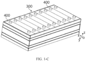
- the battery 200 may include a plurality of battery modules electrically connected to each other. As shown in FIG. 1-B , the battery 200 includes a first box body 201, a second box body 202, and a plurality of battery modules 300. The first box body 201 and the second box body 202 are fastened together, and the plurality of battery modules 300 are arranged in a space enclosed by the first box body 201 and the second box body 202. In some embodiments, the first box body 201 and the second box body 202 are connected in a sealed manner.
- the battery module 300 includes a plurality of battery cells 400, and the plurality of battery cells 400 may be electrically connected in a series, parallel, or hybrid manner to implement a larger current or voltage.
- the hybrid connection refers to a combination of series connection and parallel connection.
- the battery cell 400 may be placed vertically, a height direction of the battery cell 400 is consistent with the direction z, a length direction of the battery cell 400 is consistent with the direction x, and a plurality of battery cells 400 is arranged side by side along a width direction in the direction y.
- the battery cell 400 may be laid flat, the width direction of the battery cell 400 is consistent with the direction z, the length direction of the battery cell 400 is consistent with the direction x, and the plurality of battery cells 400 are stacked for at least one layer along the direction z.
- Each layer includes a plurality of battery cells 400 spaced apart along the direction x.
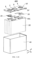
- the battery cell 400 includes a housing body 40, an electrode assembly 30, and an end cover assembly 10.
- the end cover assembly 10 includes an end cover plate 10', and the end cover plate 10' is connected (for example, being welded) to the housing body 40, to form a housing of the battery cell 400.
- the electrode assembly 30 is disposed in the housing body 40, and the housing body 40 is filled with electrolyte.
- the battery cell 400 may be of a cubic shape, a rectangular shape, or a cylindrical shape.
- the tab 301 of the electrode assembly 30 is located at the top, the positive tab is connected to the positive terminal through one connecting member 20, and the negative tab is connected to the negative terminal through the other connecting member 20.
- the battery cell 400 may include two end cover assemblies 10, respectively disposed at two ends of the housing body 40, and each end cover assembly 10 is provided with one electrode terminal 5.
- Actuate described in this application means that the pressure relief mechanism 6 performs an action or is activated to a specific state, so that the internal pressure of the battery cell 400 can be relieved.
- the action performed by the pressure relief mechanism 6 may include but is not limited to: cracking, breaking, tearing, or opening at least part of the pressure relief mechanism 6, or the like.
- the end cover plate 10' is provided with a through hole for injecting the electrolyte into the battery cell 400.
- the through hole may be a round hole, an elliptical hole, a polygonal hole, or holes of other shapes, and may extend along the height direction of the end cover plate 10'.
- the end cover plate 10 is provided with an injection member 2 for closing the through hole.
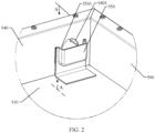
- a box body 500 applied to battery 200 provided in this embodiment of this application includes a carrying plate 510 and a one-way gravity valve 520.
- the carrying plate 510 is mainly configured to carry the battery 200
- the one-way gravity valve 520 is provided on the carrying plate 510, and is configured to be closed when a gravity of liquid in the box body 500 is less than a threshold; and to be open when the gravity of the liquid in the box body 500 reaches the threshold, so as to discharge the liquid through the one-way gravity valve 520.
- the carrying plate 510 for carrying the battery 200 is usually disposed at the bottom of the box body 500. Therefore, the one-way gravity valve 520 disposed on the carrying plate 510 is also disposed at the bottom of the box body 500, helping discharge the liquid out of the box body 500.
- the device in use is the one-way gravity valve 520
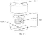
- the one-way gravity valve 520 includes a liquid discharge member 521 and a movable assembly 522.
- the liquid discharge member 521 has a first through hole 523, and the liquid discharge member 521 is configured to discharge the liquid such as the condensate and emissions through the first through hole 523 when the gravity of the liquid in the box body 500 reaches the threshold.
- the movable assembly 522 is installed on the liquid discharge member 521 and capable of moving relative to the first through hole 523, so that the movable assembly 522 seals the first through hole 523 when the gravity of the liquid in the box body 500 is less than the threshold, and opens the first through hole 523 when the gravity of the liquid in the box body 500 reaches the threshold.
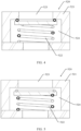
- FIG. 4 shows a case that the movable assembly 522 seals the first through hole 523 when the gravity of the liquid in the box body 500 is less than the threshold, so as to play a role of sealing the box body 500 when there is a small amount of liquid or no liquid in the box body 500.
- FIG. 5 shows a case that the movable assembly 522 opens the first through hole 523 when the gravity of the liquid in the box body 500 reaches the threshold, so as to open the first through hole 523 to discharge the liquid when there is a large amount of liquid needing to be discharged out of the box body 500. This avoids holding up the liquid in the box body 500 for a long time to affect normal use of the battery 200.
- the movable assembly 522 may be disposed at the bottom of the first through hole 523, or may be disposed on the side wall of the first through hole 523, which is not particularly limited in this embodiment of this application.
- the liquid discharge member 521 may have an accommodating chamber 524, and the movable assembly 522 may be disposed in the accommodating chamber 524 and is capable of moving up and down in the accommodating chamber 524.
- the movable assembly 522 moves up and down in the accommodating chamber 524 to seal or open the first through hole 523.
- the movable assembly 522 further includes a sealing member 5221 and an elastic member 5222.
- the sealing member 5221 is movably connected to the accommodating chamber 524 to seal or open the first through hole 523.
- the elastic member 5222 is configured to provide a preset supporting force to the sealing member 5221, and the preset supporting force is the same as the threshold, so that the sealing member 5221 can seal the first through hole 523 when the gravity of the liquid in the box body 500 is less than the preset supporting force, and open the first through hole 523 when the gravity of the liquid in the box body 500 reaches the preset supporting force, to discharge the liquid.
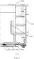
- the box body 500 provided in this embodiment of this application further includes a bottom plate 530.
- the bottom plate 530 is configured to connect to the carrying plate 510 to form a water storage chamber.
- the water storage chamber communicates with the first through hole 523, so as to collect the liquid discharged from the first through hole 523, thereby preventing the liquid out of the box body 500 from directly flowing to the electric apparatus using the battery 200 to cause safety hazards.
- the first sub-wall 5401 is provided with the liquid discharge hole 5403, that is, the liquid discharge hole 5403 penetrates through only the first sub-wall 5401 of the first wall 540, so that the liquid whose height of the liquid surface in the direction of gravity is greater than or equal to that of the liquid discharge hole 5403 is collected in the hollow chamber and the liquid in the box body 500 can be discharged in a timely manner.
- the condensing part 550 is disposed on the inner surface of the box body 500 at a position opposite the vent hole 5404, so that gas flowing from the vent hole 5404 first comes in contact with the condensing part 550, to achieve a purpose of preventing the gas from condensing in the box body and then coming in contact with conductive members inside the box body.
- the box body 500 further includes a thermal management component 560.
- the thermal management component 560 is configured to adjust a temperature of the battery 200.
- the thermal management component 560 intersects the first wall 540 to enter the box body 500 through the first wall 540, thereby implementing temperature adjustment for the battery 200.
- the thermal management component 560 may be a component such as a water cooling plate, which is not particularly limited in this embodiment of this application.
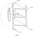
- the cover-like structure of the condensing part 550 is further provided with a flow channel 5502, and the flow channel 5502 is configured to guide the condensate of the cover-like structure to the one-way gravity valve 520. Portions of the condensing part 550 on two sides of the flow channel 5502 are attached to the first wall 540.
- the cover-like structure has a second opening 5503 corresponding to the flow channel 5502, and the second opening 5503 is configured to guide the condensate on the cover-like structure to the flow channel 5502 and then into the one-way gravity valve 520 through the flow channel 5502.
- the one-way gravity valve 520 is further configured to discharge the condensate out of the box body 500 from the flow channel 5502 when a gravity of the condensate in the flow channel 5502 reaches the threshold.
- the second opening 5503 is provided in a second direction of the cover-like structure, and the second direction is the direction of gravity.
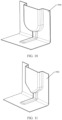
- the box body 500 further includes a liquid storage member 580 disposed on the inner surface of the box body 500, and the liquid storage member 580 is configured to, when the height of the liquid surface of the liquid in the box body 500 in the direction of gravity reaches a height of the liquid storage member 580, store liquid that flows into the liquid storage member 580, and discharge the liquid flowing into the liquid storage member 580 to the one-way gravity valve 520.
- the liquid storage member 580 includes a height-limiting plate 5801 and a guiding plate 5802.
- the height-limiting plate 5801 comes in contact with the inner surface of the first sub-wall 5401, and the height-limiting plate 5801 and the first sub-wall 5401 form a liquid height-limiting cavity 5803 with an opening on the top in the direction of gravity.
- the liquid height-limiting cavity 5803 is configured to allow flowing of the liquid when a surface of the liquid is higher than the liquid height-limiting cavity 5803 in the direction of gravity.
- the guiding plate 5802 comes in contact with a surface of the carrying plate 510 facing toward the battery cell 400, and a guiding channel is provided between the guiding plate 5802 and the carrying plate 510. Two ends of the guiding channel communicate with the liquid height-limiting cavity 5803 and the one-way gravity valve 520 respectively.
- the guiding channel is configured to discharge the liquid from the liquid height-limiting cavity 5803 to the one-way gravity valve 520.
- the battery in this embodiment of this application is provided with the box body, and the box body is provided with the one-way gravity valve.
- a time for discharging the liquid in the box body is determined based on the threshold of the one-way gravity valve.
- the liquid in the box body can be discharged in a timely manner, thereby reducing safety hazards and improving service life of the battery.
- the small amount of liquid in the box body can play a role of cooling the battery inside the box body under the premise of not affecting safety performance of the battery.
- this application further provides an electric apparatus.
- the electric apparatus includes the battery 200 described above, and the battery 200 is configured to supply electrical energy.
- the battery 200 is disposed in the box body 500, and the box body 500 can discharge the liquid outside in a timely, so as to prevent the liquid from being held up in the box body 500 for a long time and cause potential safety hazard.
- the specific structural form and working principle of the box body 500 have been described in detail in the foregoing embodiment, and details are not repeated in this embodiment.
- an embodiment of this application further provides a method for preparing battery. As shown in FIG. 14 , the method for preparing battery may include the following steps.
- Step S1410 Install a battery on a carrying plate.
- Step S1420 Dispose a one-way gravity valve on the carrying plate, where the one-way gravity valve is configured to be closed when a gravity of liquid in the box body is less than a threshold, and to be open when the gravity of the liquid in the box body reaches the threshold, so as to discharge the liquid through the one-way gravity valve.
- the battery 200 is disposed in the box body 500.
- the liquid can be discharged through the one-way gravity valve 520 disposed in the box body 500, thereby reducing potential safety hazards and improving service life of the battery 200.
- the box body 500 further includes other components, and the components can be manufactured by using a corresponding method to finally obtain the box body 500 as required that is convenient for liquid discharge.
- any methods for manufacturing related components and connecting related components fall within the protection scope of the embodiments of this application, and details are not described in the embodiments of this application.
- the first apparatus 1510 may be configured to install a battery on a carrying plate, where the carrying plate is part of a box body and is disposed at the bottom of the box body.
- the second apparatus 1520 may be configured to dispose a one-way gravity valve on the carrying plate.
- the one-way gravity valve is configured to be closed when a gravity of liquid in the box body is less than a threshold, and to be open when the gravity of the liquid in the box body reaches the threshold, so as to discharge the liquid through the one-way gravity valve.
Landscapes
- Chemical & Material Sciences (AREA)
- Chemical Kinetics & Catalysis (AREA)
- Electrochemistry (AREA)
- General Chemical & Material Sciences (AREA)
- Engineering & Computer Science (AREA)
- Manufacturing & Machinery (AREA)
- Health & Medical Sciences (AREA)
- Public Health (AREA)
- Business, Economics & Management (AREA)
- Emergency Management (AREA)
- Aviation & Aerospace Engineering (AREA)
- Battery Mounting, Suspending (AREA)
- Gas Exhaust Devices For Batteries (AREA)
- Secondary Cells (AREA)
Claims (12)
- Gehäusekörper (500) zum Aufnehmen einer Batterie, der Folgendes aufweist:eine Trägerplatte (510), die zum Tragen einer Batterie (200) ausgebildet ist;ein Ein-Weg-Schwerkraftventil (520), das an der Trägerplatte (510) angeordnet ist; wobeidas Ein-Weg-Schwerkraftventil (520) so ausgebildet ist, dass es geschlossen ist, wenn eine Schwerkraft von Flüssigkeit im Gehäusekörper (500) kleiner als ein Schwellenwert ist, und offen ist, wenn die Schwerkraft der Flüssigkeit im Gehäusekörper (500) den Schwellenwert erreicht, um die Flüssigkeit durch das Ein-Weg-Schwerkraftventil (520) abzulassen; undein Flüssigkeitsspeicherelement (580), das an der Innenfläche des Gehäusekörpers (500) angeordnet ist, und wobei das Flüssigkeitsspeicherelement (580) ausgebildet ist, um, wenn die Höhe einer Flüssigkeitsoberfläche der Flüssigkeit im Gehäusekörper (500) in Richtung der Schwerkraft eine Höhe des Flüssigkeitsspeicherelements (580) erreicht, Flüssigkeit zu speichern, die in das Flüssigkeitsspeicherelement (580) fließt, und die in das Flüssigkeitsspeicherelement (580) fließende Flüssigkeit zu dem Ein-Weg-Schwerkraftventil (520) abzulassen;wobei der Schwellenwert erreicht ist, wenn die Höhe der Flüssigkeitsoberfläche der Flüssigkeit im Gehäusekörper (500) in Richtung der Schwerkraft die Höhe des Flüssigkeitsspeicherelements (580) erreicht, wobei das Ein-Weg-Schwerkraftventil (520) Folgendes aufweist:ein Flüssigkeitsabflusselement (521), das mit einem ersten Durchgangsloch (523) versehen ist, wobei das Flüssigkeitsabflusselement (521) zum Ablassen der Flüssigkeit durch das erste Durchgangsloch (523), wenn die Schwerkraft der Flüssigkeit im Gehäusekörper (500) den Schwellenwert erreicht, ausgebildet ist; undeine bewegliche Anordnung (522), die an dem Flüssigkeitsabflusselement (521) installiert ist und sich relativ zu dem ersten Durchgangsloch (523) bewegen kann, so dass die bewegliche Anordnung (522) das erste Durchgangsloch (523) verschließt, wenn die Schwerkraft der Flüssigkeit im Gehäusekörper (500) niedriger als der Schwellenwert ist, und das erste Durchgangsloch (523) öffnet, wenn die Schwerkraft der Flüssigkeit im Gehäusekörper (500) den Schwellenwert erreicht, und ferner eine Bodenplatte (530) aufweist, die zum Verbinden mit der Trägerplatte (510) zu einer Wasserspeicherkammer ausgebildet ist, wobei die Wasserspeicherkammer mit dem ersten Durchgangsloch (523) kommuniziert, um die aus dem ersten Durchgangsloch (523) abgelassene Flüssigkeit zu sammeln; wobei der Gehäusekörper (500) ferner eine erste Wand (540) aufweist, die zum Verbinden mit der Trägerplatte (510) zu einer Aufnahmekammer (524) zum Aufnehmen der Batterie (200) ausgebildet ist, wobei die erste Wand (540) mit einem Flüssigkeitsablassloch (5403) versehen ist und das Flüssigkeitsablassloch (5403) zum Ablassen von Flüssigkeit ausgebildet ist, die eine Höhe des Flüssigkeitsablasslochs (5403) übersteigt, wenn eine Höhe einer Flüssigkeitsoberfläche der Flüssigkeit im Gehäusekörper (500) in Richtung der Schwerkraft größer als oder so groß wie die des Flüssigkeitsablasslochs (5403) ist; undwobei die erste Wand (540) ferner ein Lüftungsloch (5404) aufweist und das Lüftungsloch (5404) zum Kommunizieren mit dem Inneren und dem Äußeren des Gehäusekörpers (500) ausgebildet ist; und der Gehäusekörper (500) ferner ein kondensierendes Teil (550) aufweist, das zum Blockieren des Lüftungslochs (5404) ausgebildet ist, um durch das Lüftungsloch (5404) in den Gehäusekörper (500) strömendes Gas zu kondensieren.
- Gehäusekörper (500) nach Anspruch 1, wobei die erste Wand (540) eine erste Teilwand (5401) und eine zweite Teilwand (5402) aufweist, zwischen der ersten Teilwand (5401) und der zweiten Teilwand (5402) eine hohle Kammer gebildet ist, die erste Teilwand (5401) eine Innenwand des Gehäusekörpers (500) ist, die zweite Teilwand (5402) eine Außenwand des Gehäusekörpers (500) ist und die erste Teilwand (5401) mit dem Flüssigkeitsablassloch (5403) versehen ist, so dass die Flüssigkeit, deren Höhe der Flüssigkeitsoberfläche in Richtung der Schwerkraft größer als oder so groß wie die des Flüssigkeitsablasslochs (5403) ist, in der hohlen Kammer gesammelt wird.
- Gehäusekörper (500) nach Anspruch 1 oder 2, wobei das kondensierendes Teil (550) an einer Innenfläche des Gehäusekörpers (500) bereitgestellt ist.
- Gehäusekörper (500) nach einem der vorhergehenden Ansprüche, wobei der Gehäusekörper (500) ferner eine Wärmemanagementkomponente (560) aufweist, wobei die Wärmemanagementkomponente (560) zum Regulieren einer Temperatur der Batterie (200) ausgebildet ist, die Wärmemanagementkomponente (560) die erste Wand (540) schneidet, ein erster Abschnitt des kondensierenden Teils (550) sich entlang der Wärmemanagementkomponente (560) erstreckt, um an der Wärmemanagementkomponente (560) angebracht zu werden, und ein zweiter Abschnitt des kondensierenden Teils (550) sich entlang der ersten Wand (540) erstreckt, um das Lüftungsloch (5404) zu blockieren.
- Gehäusekörper (500) nach einem der vorhergehenden Ansprüche, wobei das kondensierende Teil (550) ein abdeckungsähnliches Gebilde aufweist und das abdeckungsähnliche Gebilde das Lüftungsloch (5404) blockiert, wobei das abdeckungsähnliche Gebilde bevorzugt an einer umgebenden Region des Lüftungslochs (5404) an der ersten Wand (540) angebracht ist und mit einer ersten Öffnung (5501) versehen ist, durch die Gas in den Gehäusekörper (500) strömt, mehr bevorzugt die erste Öffnung (5501) in einer ersten Richtung des abdeckungsähnlichen Gebildes bereitgestellt ist und die erste Richtung eine der Richtung der Schwerkraft entgegengesetzte Richtung ist und noch mehr bevorzugt die erste Öffnung ferner zum Sammeln von an einer Rohrverbindung eines Brandschutzsystems ausgetretenem Fluid im Fall eines Fluidaustritts an der Verbindung ausgebildet ist.
- Gehäusekörper (500) nach Anspruch 5, wobei das kondensierende Teil (550) ferner einen Strömungskanal (5502) aufweist und der Strömungskanal (5502) zum Leiten eines Kondensats an dem abdeckungsähnlichen Gebilde zu dem Ein-Weg-Schwerkraftventil (520) ausgebildet ist und, bevorzugt, wobei Abschnitte des kondensierenden Teils (550) auf zwei Seiten des Strömungskanals (5502) an der ersten Wand (540) angebracht sind.
- Gehäusekörper (500) nach Anspruch 6, wobei das abdeckungsähnliche Gebilde mit einer zweiten Öffnung (5503) versehen ist, die dem Strömungskanal (5502) entspricht, und die zweite Öffnung (5503) zum Führen des Kondensats an dem abdeckungsähnlichen Gebilde zum Strömungskanal (5502) ausgebildet ist und, bevorzugt, wobei die zweite Öffnung (5503) in einer zweiten Richtung des abdeckungsähnlichen Gebildes bereitgestellt ist und die zweite Richtung die Richtung der Schwerkraft ist.
- Gehäusekörper (500) nach einem der vorhergehenden Ansprüche, wobei der Gehäusekörper (500) ferner Folgendes aufweist:einen Druckausgleichmechanismus (570), der zum Ausgleichen von Druck inner- und außerhalb des Gehäusekörpers (500) ausgebildet ist, und, bevorzugt, wobei der Druckausgleichmechanismus (570) an der zweiten Teilwand (5402) bereitgestellt ist und von außerhalb des Gehäusekörpers (500) durch den Druckausgleichmechanismus (570) zu der hohlen Kammer strömendes Gas durch das Lüftungsloch (5404) in den Gehäusekörper (500) strömt.
- Batterie (200), die den Gehäusekörper (500) nach einem der Ansprüche 1 bis 8 aufweist, wobei der Gehäusekörper (500) zum Aufnehmen der Batterie (200) ausgebildet ist.
- Elektrische Vorrichtung, die die Batterie (200) nach Anspruch 9 aufweist, wobei die Batterie (200) zur Bereitstellung elektrischer Energie ausgebildet ist.
- Verfahren zur Herstellung einer Batterie, das Folgendes aufweist:Installieren einer Batterie (200) auf einer Trägerplatte (510) eines Gehäusekörpers (500) nach einem der Ansprüche 1 bis 8; undAnordnen eines Ein-Weg-Schwerkraftventils (520) an der Trägerplatte (510); wobeidas Ein-Weg-Schwerkraftventil (520) so ausgebildet ist, dass es geschlossen ist, wenn eine Schwerkraft von Flüssigkeit im Gehäusekörper (500) kleiner als ein Schwellenwert ist, und offen ist, wenn die Schwerkraft der Flüssigkeit im Gehäusekörper (500) den Schwellenwert erreicht, um die Flüssigkeit durch das Ein-Weg-Schwerkraftventil (520) abzulassen.
- Einrichtung (1500) zur Herstellung einer Batterie, die Folgendes aufweist:eine erste Vorrichtung (1501), die zum Installieren einer Batterie (200) auf einer Trägerplatte (510) eines Gehäusekörpers (500) nach einem der Ansprüche 1 bis 8 ausgebildet ist; undeine zweite Vorrichtung (1502), die zum Anordnen eines Ein-Weg-Schwerkraftventils (520) auf der Trägerplatte (510) ausgebildet ist; wobeidas Ein-Weg-Schwerkraftventil (520) so ausgebildet ist, dass es geschlossen ist, wenn eine Schwerkraft von Flüssigkeit im Gehäusekörper (500) kleiner als ein Schwellenwert ist, und offen ist, wenn die Schwerkraft der Flüssigkeit im Gehäusekörper (500) den Schwellenwert erreicht, um die Flüssigkeit durch das Ein-Weg-Schwerkraftventil (520) abzulassen.
Priority Applications (1)
| Application Number | Priority Date | Filing Date | Title |
|---|---|---|---|
| HUE20957976A HUE068408T2 (hu) | 2020-10-19 | 2020-10-19 | Doboztest akkumulátorhoz, akkumulátor, elektromos berendezés, valamint eljárás és eszköz akkumulátor elõállításához |
Applications Claiming Priority (1)
| Application Number | Priority Date | Filing Date | Title |
|---|---|---|---|
| PCT/CN2020/121996 WO2022082393A1 (zh) | 2020-10-19 | 2020-10-19 | 用于电池的箱体、电池、用电装置、制备电池的方法和设备 |
Publications (4)
| Publication Number | Publication Date |
|---|---|
| EP4064449A1 EP4064449A1 (de) | 2022-09-28 |
| EP4064449A4 EP4064449A4 (de) | 2023-09-27 |
| EP4064449B1 true EP4064449B1 (de) | 2024-07-10 |
| EP4064449C0 EP4064449C0 (de) | 2024-07-10 |
Family
ID=81289524
Family Applications (1)
| Application Number | Title | Priority Date | Filing Date |
|---|---|---|---|
| EP20957976.2A Active EP4064449B1 (de) | 2020-10-19 | 2020-10-19 | Gehäusekörper für batterie, batterie, elektrisches gerät und verfahren und batterieherstellungsverfahren und -vorrichtung |
Country Status (6)
| Country | Link |
|---|---|
| US (1) | US11894583B2 (de) |
| EP (1) | EP4064449B1 (de) |
| JP (1) | JP7513751B2 (de) |
| KR (1) | KR102707154B1 (de) |
| HU (1) | HUE068408T2 (de) |
| WO (1) | WO2022082393A1 (de) |
Families Citing this family (4)
| Publication number | Priority date | Publication date | Assignee | Title |
|---|---|---|---|---|
| CN116557615B (zh) * | 2023-07-11 | 2023-12-01 | 宁德时代新能源科技股份有限公司 | 电磁排液阀、电池及用电装置 |
| CN116683116B (zh) * | 2023-07-20 | 2023-12-22 | 宁德时代新能源科技股份有限公司 | 电池的排液阀、电池以及用电装置 |
| DE212024000109U1 (de) * | 2023-11-09 | 2025-07-21 | Eve Power Co., Ltd. | Batterie und Batteriepack |
| CN117317446A (zh) * | 2023-11-09 | 2023-12-29 | 湖北亿纬动力有限公司 | 一种均热板及电池组件 |
Family Cites Families (14)
| Publication number | Priority date | Publication date | Assignee | Title |
|---|---|---|---|---|
| WO2006098130A1 (ja) * | 2005-03-14 | 2006-09-21 | Nec Lamilion Energy, Ltd. | フィルム外装電気デバイス用筐体 |
| WO2010064255A1 (en) | 2008-12-05 | 2010-06-10 | Shatendra Kumar Sharma | An improved battery casing for enhanced battery performance and life |
| JP2012094313A (ja) | 2010-10-26 | 2012-05-17 | Sanyo Electric Co Ltd | バッテリー装置の冷却構造 |
| JP5691992B2 (ja) | 2011-10-18 | 2015-04-01 | 三菱自動車工業株式会社 | 電動車両のバッテリパック搭載構造 |
| KR102198000B1 (ko) * | 2014-02-17 | 2021-01-04 | 삼성에스디아이 주식회사 | 배터리 팩용 케이스 |
| CN203910893U (zh) * | 2014-05-28 | 2014-10-29 | 沭阳天泓工贸有限公司 | 高阻燃abs可倒置电池外壳 |
| JP2016062712A (ja) * | 2014-09-17 | 2016-04-25 | トヨタ自動車株式会社 | 全固体リチウム二次電池の製造方法 |
| JP6350480B2 (ja) | 2015-10-05 | 2018-07-04 | トヨタ自動車株式会社 | 密閉型電池 |
| CN105762428B (zh) * | 2016-03-03 | 2019-06-04 | 宁德时代新能源科技股份有限公司 | 电池包 |
| CN207250619U (zh) * | 2017-09-11 | 2018-04-17 | 惠州市蓝微新源技术有限公司 | 一种电池包箱体的单向阀 |
| CN207441811U (zh) * | 2017-11-20 | 2018-06-01 | 宁德时代新能源科技股份有限公司 | 箱体及电池包 |
| CN207441762U (zh) * | 2017-11-29 | 2018-06-01 | 宁德时代新能源科技股份有限公司 | 箱体组件和电池箱 |
| JP6729625B2 (ja) | 2018-04-06 | 2020-07-22 | トヨタ自動車株式会社 | 蓄電装置 |
| CN111584792B (zh) * | 2020-04-21 | 2022-11-29 | 重庆金康动力新能源有限公司 | 一种电池模组 |
-
2020
- 2020-10-19 WO PCT/CN2020/121996 patent/WO2022082393A1/zh not_active Ceased
- 2020-10-19 JP JP2022567658A patent/JP7513751B2/ja active Active
- 2020-10-19 KR KR1020227038503A patent/KR102707154B1/ko active Active
- 2020-10-19 HU HUE20957976A patent/HUE068408T2/hu unknown
- 2020-10-19 EP EP20957976.2A patent/EP4064449B1/de active Active
-
2022
- 2022-11-10 US US18/054,314 patent/US11894583B2/en active Active
Also Published As
| Publication number | Publication date |
|---|---|
| EP4064449A4 (de) | 2023-09-27 |
| US11894583B2 (en) | 2024-02-06 |
| HUE068408T2 (hu) | 2024-12-28 |
| JP2023525281A (ja) | 2023-06-15 |
| EP4064449A1 (de) | 2022-09-28 |
| JP7513751B2 (ja) | 2024-07-09 |
| KR20220163454A (ko) | 2022-12-09 |
| EP4064449C0 (de) | 2024-07-10 |
| WO2022082393A1 (zh) | 2022-04-28 |
| KR102707154B1 (ko) | 2024-09-13 |
| US20230084044A1 (en) | 2023-03-16 |
Similar Documents
| Publication | Publication Date | Title |
|---|---|---|
| US12212015B2 (en) | Battery, and related device, preparation method and preparation apparatus thereof | |
| KR102875256B1 (ko) | 배터리 및 관련 장치, 제조 방법 및 제조 장치 | |
| CN213782158U (zh) | 电池、包括电池的装置和制备电池的设备 | |
| US11894583B2 (en) | Box body applied to battery, battery assembly, electric apparatus, and method and device for preparing battery assembly | |
| KR102686170B1 (ko) | 전지 및 그 관련장치, 제조방법 및 제조설비 | |
| KR102834684B1 (ko) | 배터리 및 그 관련 장치, 제조 방법 및 제조 장치 | |
| US20220328927A1 (en) | Battery, electric apparatus, and method and device for preparing battery | |
| JP7784521B2 (ja) | 電池、電力消費機器、電池の製造方法及び機器 | |
| KR102804168B1 (ko) | 배터리, 전기 장치, 배터리의 제조 방법 및 제조 장치 | |
| JP7580575B2 (ja) | 電池、電気装置、電池の製造方法および装置 | |
| CN112018320B (zh) | 用于电池的箱体、电池、用电装置、制备电池的方法和设备 | |
| JP7594658B2 (ja) | 電池単体、その製造方法および製造システム、電池および電力使用装置 | |
| US20240347822A1 (en) | End cover assembly, battery cell, battery, and electrical apparatus | |
| EP4009433B1 (de) | Batterie, stromverbrauchsvorrichtung und verfahren und vorrichtung zur herstellung einer batterie | |
| KR102724404B1 (ko) | 배터리, 전기 장치 및 배터리 제조 방법, 기기 | |
| EP4016713B1 (de) | Boxkörper für batterie, batterie und stromverbrauchsvorrichtung | |
| EP4254591B1 (de) | Batterie, elektrische vorrichtung sowie verfahren und vorrichtung zur herstellung der batterie | |
| KR20250002669A (ko) | 전지 셀, 전지 및 전기 장치 | |
| JP7741310B2 (ja) | 筐体、電池、電気装置、電池を製造する方法及び装置 | |
| RU2805991C1 (ru) | Батарея и связанное с ней устройство, способ ее изготовления и устройство для ее изготовления |
Legal Events
| Date | Code | Title | Description |
|---|---|---|---|
| STAA | Information on the status of an ep patent application or granted ep patent |
Free format text: STATUS: THE INTERNATIONAL PUBLICATION HAS BEEN MADE |
|
| PUAI | Public reference made under article 153(3) epc to a published international application that has entered the european phase |
Free format text: ORIGINAL CODE: 0009012 |
|
| STAA | Information on the status of an ep patent application or granted ep patent |
Free format text: STATUS: REQUEST FOR EXAMINATION WAS MADE |
|
| 17P | Request for examination filed |
Effective date: 20220623 |
|
| AK | Designated contracting states |
Kind code of ref document: A1 Designated state(s): AL AT BE BG CH CY CZ DE DK EE ES FI FR GB GR HR HU IE IS IT LI LT LU LV MC MK MT NL NO PL PT RO RS SE SI SK SM TR |
|
| A4 | Supplementary search report drawn up and despatched |
Effective date: 20230824 |
|
| RIC1 | Information provided on ipc code assigned before grant |
Ipc: H01M 50/204 20210101ALI20230818BHEP Ipc: H01M 10/42 20060101ALI20230818BHEP Ipc: H01M 50/691 20210101AFI20230818BHEP |
|
| DAV | Request for validation of the european patent (deleted) | ||
| DAX | Request for extension of the european patent (deleted) | ||
| GRAP | Despatch of communication of intention to grant a patent |
Free format text: ORIGINAL CODE: EPIDOSNIGR1 |
|
| STAA | Information on the status of an ep patent application or granted ep patent |
Free format text: STATUS: GRANT OF PATENT IS INTENDED |
|
| RIC1 | Information provided on ipc code assigned before grant |
Ipc: H01M 50/673 20210101ALI20240326BHEP Ipc: H01M 50/584 20210101ALI20240326BHEP Ipc: H01M 50/30 20210101ALI20240326BHEP Ipc: H01M 50/249 20210101ALI20240326BHEP Ipc: H01M 50/24 20210101ALI20240326BHEP Ipc: H01M 50/202 20210101ALI20240326BHEP Ipc: H01M 10/625 20140101ALI20240326BHEP Ipc: H01M 10/613 20140101ALI20240326BHEP Ipc: H01M 50/204 20210101ALI20240326BHEP Ipc: H01M 10/42 20060101ALI20240326BHEP Ipc: H01M 50/691 20210101AFI20240326BHEP |
|
| INTG | Intention to grant announced |
Effective date: 20240422 |
|
| GRAS | Grant fee paid |
Free format text: ORIGINAL CODE: EPIDOSNIGR3 |
|
| GRAA | (expected) grant |
Free format text: ORIGINAL CODE: 0009210 |
|
| STAA | Information on the status of an ep patent application or granted ep patent |
Free format text: STATUS: THE PATENT HAS BEEN GRANTED |
|
| RAP3 | Party data changed (applicant data changed or rights of an application transferred) |
Owner name: JIANGSU CONTEMPORARY AMPEREX TECHNOLOGY LIMITED |
|
| RIN1 | Information on inventor provided before grant (corrected) |
Inventor name: XU, CHENYI Inventor name: HU, LANGCHAO Inventor name: YANG, HAIQI Inventor name: WANG, WENLI Inventor name: HUANG, XIAOTENG Inventor name: HONG, JIARONG Inventor name: LIANG, CHENGDU |
|
| AK | Designated contracting states |
Kind code of ref document: B1 Designated state(s): AL AT BE BG CH CY CZ DE DK EE ES FI FR GB GR HR HU IE IS IT LI LT LU LV MC MK MT NL NO PL PT RO RS SE SI SK SM TR |
|
| REG | Reference to a national code |
Ref country code: CH Ref legal event code: EP |
|
| REG | Reference to a national code |
Ref country code: DE Ref legal event code: R096 Ref document number: 602020033944 Country of ref document: DE |
|
| U01 | Request for unitary effect filed |
Effective date: 20240805 |
|
| U07 | Unitary effect registered |
Designated state(s): AT BE BG DE DK EE FI FR IT LT LU LV MT NL PT SE SI Effective date: 20240819 |
|
| U20 | Renewal fee for the european patent with unitary effect paid |
Year of fee payment: 5 Effective date: 20241023 |
|
| REG | Reference to a national code |
Ref country code: HU Ref legal event code: AG4A Ref document number: E068408 Country of ref document: HU |
|
| PG25 | Lapsed in a contracting state [announced via postgrant information from national office to epo] |
Ref country code: NO Free format text: LAPSE BECAUSE OF FAILURE TO SUBMIT A TRANSLATION OF THE DESCRIPTION OR TO PAY THE FEE WITHIN THE PRESCRIBED TIME-LIMIT Effective date: 20241010 |
|
| PG25 | Lapsed in a contracting state [announced via postgrant information from national office to epo] |
Ref country code: GR Free format text: LAPSE BECAUSE OF FAILURE TO SUBMIT A TRANSLATION OF THE DESCRIPTION OR TO PAY THE FEE WITHIN THE PRESCRIBED TIME-LIMIT Effective date: 20241011 Ref country code: PL Free format text: LAPSE BECAUSE OF FAILURE TO SUBMIT A TRANSLATION OF THE DESCRIPTION OR TO PAY THE FEE WITHIN THE PRESCRIBED TIME-LIMIT Effective date: 20240710 |
|
| PG25 | Lapsed in a contracting state [announced via postgrant information from national office to epo] |
Ref country code: IS Free format text: LAPSE BECAUSE OF FAILURE TO SUBMIT A TRANSLATION OF THE DESCRIPTION OR TO PAY THE FEE WITHIN THE PRESCRIBED TIME-LIMIT Effective date: 20241110 |
|
| PG25 | Lapsed in a contracting state [announced via postgrant information from national office to epo] |
Ref country code: HR Free format text: LAPSE BECAUSE OF FAILURE TO SUBMIT A TRANSLATION OF THE DESCRIPTION OR TO PAY THE FEE WITHIN THE PRESCRIBED TIME-LIMIT Effective date: 20240710 |
|
| PG25 | Lapsed in a contracting state [announced via postgrant information from national office to epo] |
Ref country code: RS Free format text: LAPSE BECAUSE OF FAILURE TO SUBMIT A TRANSLATION OF THE DESCRIPTION OR TO PAY THE FEE WITHIN THE PRESCRIBED TIME-LIMIT Effective date: 20241010 Ref country code: ES Free format text: LAPSE BECAUSE OF FAILURE TO SUBMIT A TRANSLATION OF THE DESCRIPTION OR TO PAY THE FEE WITHIN THE PRESCRIBED TIME-LIMIT Effective date: 20240710 |
|
| PG25 | Lapsed in a contracting state [announced via postgrant information from national office to epo] |
Ref country code: RS Free format text: LAPSE BECAUSE OF FAILURE TO SUBMIT A TRANSLATION OF THE DESCRIPTION OR TO PAY THE FEE WITHIN THE PRESCRIBED TIME-LIMIT Effective date: 20241010 Ref country code: PL Free format text: LAPSE BECAUSE OF FAILURE TO SUBMIT A TRANSLATION OF THE DESCRIPTION OR TO PAY THE FEE WITHIN THE PRESCRIBED TIME-LIMIT Effective date: 20240710 Ref country code: NO Free format text: LAPSE BECAUSE OF FAILURE TO SUBMIT A TRANSLATION OF THE DESCRIPTION OR TO PAY THE FEE WITHIN THE PRESCRIBED TIME-LIMIT Effective date: 20241010 Ref country code: IS Free format text: LAPSE BECAUSE OF FAILURE TO SUBMIT A TRANSLATION OF THE DESCRIPTION OR TO PAY THE FEE WITHIN THE PRESCRIBED TIME-LIMIT Effective date: 20241110 Ref country code: HR Free format text: LAPSE BECAUSE OF FAILURE TO SUBMIT A TRANSLATION OF THE DESCRIPTION OR TO PAY THE FEE WITHIN THE PRESCRIBED TIME-LIMIT Effective date: 20240710 Ref country code: GR Free format text: LAPSE BECAUSE OF FAILURE TO SUBMIT A TRANSLATION OF THE DESCRIPTION OR TO PAY THE FEE WITHIN THE PRESCRIBED TIME-LIMIT Effective date: 20241011 Ref country code: ES Free format text: LAPSE BECAUSE OF FAILURE TO SUBMIT A TRANSLATION OF THE DESCRIPTION OR TO PAY THE FEE WITHIN THE PRESCRIBED TIME-LIMIT Effective date: 20240710 |
|
| PG25 | Lapsed in a contracting state [announced via postgrant information from national office to epo] |
Ref country code: SM Free format text: LAPSE BECAUSE OF FAILURE TO SUBMIT A TRANSLATION OF THE DESCRIPTION OR TO PAY THE FEE WITHIN THE PRESCRIBED TIME-LIMIT Effective date: 20240710 |
|
| PG25 | Lapsed in a contracting state [announced via postgrant information from national office to epo] |
Ref country code: CZ Free format text: LAPSE BECAUSE OF FAILURE TO SUBMIT A TRANSLATION OF THE DESCRIPTION OR TO PAY THE FEE WITHIN THE PRESCRIBED TIME-LIMIT Effective date: 20240710 |
|
| PG25 | Lapsed in a contracting state [announced via postgrant information from national office to epo] |
Ref country code: SK Free format text: LAPSE BECAUSE OF FAILURE TO SUBMIT A TRANSLATION OF THE DESCRIPTION OR TO PAY THE FEE WITHIN THE PRESCRIBED TIME-LIMIT Effective date: 20240710 |
|
| PLBE | No opposition filed within time limit |
Free format text: ORIGINAL CODE: 0009261 |
|
| STAA | Information on the status of an ep patent application or granted ep patent |
Free format text: STATUS: NO OPPOSITION FILED WITHIN TIME LIMIT |
|
| REG | Reference to a national code |
Ref country code: CH Ref legal event code: PL |
|
| 26N | No opposition filed |
Effective date: 20250411 |
|
| PG25 | Lapsed in a contracting state [announced via postgrant information from national office to epo] |
Ref country code: MC Free format text: LAPSE BECAUSE OF FAILURE TO SUBMIT A TRANSLATION OF THE DESCRIPTION OR TO PAY THE FEE WITHIN THE PRESCRIBED TIME-LIMIT Effective date: 20240710 |
|
| PG25 | Lapsed in a contracting state [announced via postgrant information from national office to epo] |
Ref country code: CH Free format text: LAPSE BECAUSE OF NON-PAYMENT OF DUE FEES Effective date: 20241031 |
|
| PG25 | Lapsed in a contracting state [announced via postgrant information from national office to epo] |
Ref country code: IE Free format text: LAPSE BECAUSE OF NON-PAYMENT OF DUE FEES Effective date: 20241019 |
|
| PGFP | Annual fee paid to national office [announced via postgrant information from national office to epo] |
Ref country code: HU Payment date: 20251007 Year of fee payment: 6 |
|
| PG25 | Lapsed in a contracting state [announced via postgrant information from national office to epo] |
Ref country code: RO Free format text: LAPSE BECAUSE OF FAILURE TO SUBMIT A TRANSLATION OF THE DESCRIPTION OR TO PAY THE FEE WITHIN THE PRESCRIBED TIME-LIMIT Effective date: 20240710 |
|
| U20 | Renewal fee for the european patent with unitary effect paid |
Year of fee payment: 6 Effective date: 20251021 |
|
| PGFP | Annual fee paid to national office [announced via postgrant information from national office to epo] |
Ref country code: GB Payment date: 20251024 Year of fee payment: 6 |
|
| PG25 | Lapsed in a contracting state [announced via postgrant information from national office to epo] |
Ref country code: CY Free format text: LAPSE BECAUSE OF FAILURE TO SUBMIT A TRANSLATION OF THE DESCRIPTION OR TO PAY THE FEE WITHIN THE PRESCRIBED TIME-LIMIT; INVALID AB INITIO Effective date: 20201019 |