EP4064317A1 - Elektrische schutzvorrichtung und elektrische schalttafel mit einer solchen schutzvorrichtung - Google Patents
Elektrische schutzvorrichtung und elektrische schalttafel mit einer solchen schutzvorrichtung Download PDFInfo
- Publication number
- EP4064317A1 EP4064317A1 EP22164267.1A EP22164267A EP4064317A1 EP 4064317 A1 EP4064317 A1 EP 4064317A1 EP 22164267 A EP22164267 A EP 22164267A EP 4064317 A1 EP4064317 A1 EP 4064317A1
- Authority
- EP
- European Patent Office
- Prior art keywords
- latch
- drawer
- configuration
- protection device
- electrical
- Prior art date
- Legal status (The legal status is an assumption and is not a legal conclusion. Google has not performed a legal analysis and makes no representation as to the accuracy of the status listed.)
- Granted
Links
Images


Classifications
-
- H—ELECTRICITY
- H01—ELECTRIC ELEMENTS
- H01H—ELECTRIC SWITCHES; RELAYS; SELECTORS; EMERGENCY PROTECTIVE DEVICES
- H01H83/00—Protective switches, e.g. circuit-breaking switches, or protective relays operated by abnormal electrical conditions otherwise than solely by excess current
- H01H83/20—Protective switches, e.g. circuit-breaking switches, or protective relays operated by abnormal electrical conditions otherwise than solely by excess current operated by excess current as well as by some other abnormal electrical condition
- H01H83/22—Protective switches, e.g. circuit-breaking switches, or protective relays operated by abnormal electrical conditions otherwise than solely by excess current operated by excess current as well as by some other abnormal electrical condition the other condition being imbalance of two or more currents or voltages
- H01H83/226—Protective switches, e.g. circuit-breaking switches, or protective relays operated by abnormal electrical conditions otherwise than solely by excess current operated by excess current as well as by some other abnormal electrical condition the other condition being imbalance of two or more currents or voltages with differential transformer
-
- H—ELECTRICITY
- H01—ELECTRIC ELEMENTS
- H01H—ELECTRIC SWITCHES; RELAYS; SELECTORS; EMERGENCY PROTECTIVE DEVICES
- H01H71/00—Details of the protective switches or relays covered by groups H01H73/00 - H01H83/00
- H01H71/10—Operating or release mechanisms
-
- B—PERFORMING OPERATIONS; TRANSPORTING
- B64—AIRCRAFT; AVIATION; COSMONAUTICS
- B64D—EQUIPMENT FOR FITTING IN OR TO AIRCRAFT; FLIGHT SUITS; PARACHUTES; ARRANGEMENT OR MOUNTING OF POWER PLANTS OR PROPULSION TRANSMISSIONS IN AIRCRAFT
- B64D1/00—Dropping, ejecting, releasing or receiving articles, liquids, or the like, in flight
- B64D1/02—Dropping, ejecting, or releasing articles
- B64D1/04—Dropping, ejecting, or releasing articles the articles being explosive, e.g. bombs
- B64D1/06—Bomb releasing; Bomb doors
-
- B—PERFORMING OPERATIONS; TRANSPORTING
- B64—AIRCRAFT; AVIATION; COSMONAUTICS
- B64D—EQUIPMENT FOR FITTING IN OR TO AIRCRAFT; FLIGHT SUITS; PARACHUTES; ARRANGEMENT OR MOUNTING OF POWER PLANTS OR PROPULSION TRANSMISSIONS IN AIRCRAFT
- B64D7/00—Arrangement of military equipment, e.g. armaments, armament accessories or military shielding, in aircraft; Adaptations of armament mountings for aircraft
- B64D7/08—Arrangement of rocket launchers
-
- H—ELECTRICITY
- H01—ELECTRIC ELEMENTS
- H01H—ELECTRIC SWITCHES; RELAYS; SELECTORS; EMERGENCY PROTECTIVE DEVICES
- H01H71/00—Details of the protective switches or relays covered by groups H01H73/00 - H01H83/00
- H01H71/10—Operating or release mechanisms
- H01H71/12—Automatic release mechanisms with or without manual release
- H01H71/24—Electromagnetic mechanisms
-
- H—ELECTRICITY
- H01—ELECTRIC ELEMENTS
- H01H—ELECTRIC SWITCHES; RELAYS; SELECTORS; EMERGENCY PROTECTIVE DEVICES
- H01H71/00—Details of the protective switches or relays covered by groups H01H73/00 - H01H83/00
- H01H71/10—Operating or release mechanisms
- H01H71/50—Manual reset mechanisms which may be also used for manual release
- H01H71/52—Manual reset mechanisms which may be also used for manual release actuated by lever
- H01H71/528—Manual reset mechanisms which may be also used for manual release actuated by lever comprising a toggle or collapsible link between handle and contact arm, e.g. sear pin mechanism
-
- H—ELECTRICITY
- H01—ELECTRIC ELEMENTS
- H01H—ELECTRIC SWITCHES; RELAYS; SELECTORS; EMERGENCY PROTECTIVE DEVICES
- H01H83/00—Protective switches, e.g. circuit-breaking switches, or protective relays operated by abnormal electrical conditions otherwise than solely by excess current
- H01H83/14—Protective switches, e.g. circuit-breaking switches, or protective relays operated by abnormal electrical conditions otherwise than solely by excess current operated by imbalance of two or more currents or voltages, e.g. for differential protection
-
- H—ELECTRICITY
- H01—ELECTRIC ELEMENTS
- H01H—ELECTRIC SWITCHES; RELAYS; SELECTORS; EMERGENCY PROTECTIVE DEVICES
- H01H83/00—Protective switches, e.g. circuit-breaking switches, or protective relays operated by abnormal electrical conditions otherwise than solely by excess current
- H01H83/20—Protective switches, e.g. circuit-breaking switches, or protective relays operated by abnormal electrical conditions otherwise than solely by excess current operated by excess current as well as by some other abnormal electrical condition
- H01H83/22—Protective switches, e.g. circuit-breaking switches, or protective relays operated by abnormal electrical conditions otherwise than solely by excess current operated by excess current as well as by some other abnormal electrical condition the other condition being imbalance of two or more currents or voltages
-
- H—ELECTRICITY
- H01—ELECTRIC ELEMENTS
- H01H—ELECTRIC SWITCHES; RELAYS; SELECTORS; EMERGENCY PROTECTIVE DEVICES
- H01H9/00—Details of switching devices, not covered by groups H01H1/00 - H01H7/00
- H01H9/20—Interlocking, locking, or latching mechanisms
-
- H—ELECTRICITY
- H02—GENERATION; CONVERSION OR DISTRIBUTION OF ELECTRIC POWER
- H02B—BOARDS, SUBSTATIONS OR SWITCHING ARRANGEMENTS FOR THE SUPPLY OR DISTRIBUTION OF ELECTRIC POWER
- H02B1/00—Frameworks, boards, panels, desks, casings; Details of substations or switching arrangements
- H02B1/015—Boards, panels, desks; Parts thereof or accessories therefor
- H02B1/04—Mounting thereon of switches or of other devices in general, the switch or device having, or being without, casing
- H02B1/052—Mounting on rails
Definitions
- the present invention relates to an electrical protection device and an electrical panel comprising such a protection device.
- An electrical installation of a building generally comprises an electrical panel, connecting this electrical installation to a collective electricity distribution network and comprising various devices for the protection, control and monitoring of the electrical installation.
- the electrical protection devices there is known in particular a circuit breaker, which aims to protect the electrical installation, or a person, vis-à-vis an electrical fault of an electrical circuit of the installation, by opening the circuit electric.
- the circuit breaker is tripped by an overload, a short circuit or a differential electrical fault within this circuit.
- such an electrical protection device comprises a trip device, which detects a predetermined type of electrical fault and which, if necessary, triggers a switching mechanism to open the circuit.
- the trip device measures a difference between the phase currents and the neutral currents of the circuit and triggers the switching mechanism if this difference exceeds a predetermined threshold. Indeed, this difference can reflect a current leakage through the earth.
- Each device generally includes a housing which encloses the switch mechanism and the trigger, the housing being of standard size from one device to another, and being designed to be mounted on a mounting rail.
- the electrical contacts must be closed with sufficient force.
- EP-1 884 976-A1 describes, for example, a circuit breaker comprising a switching mechanism with a movable latch making it possible to change the lever arms according to operating states of the circuit breaker. Such a mechanism is relatively fragile and complex to manufacture.
- EP-3 451 360-A1 describes, for example, a circuit breaker with a locking loop which, in an unlocked position, locks the opening mechanism in the closed configuration.
- the locking loop is held in the locking position by a spring and is moved into an unlocked position by a bimetallic release or by an electromagnetic release, each of which generates a much greater force than a differential release, in particular if the circuit breaker is energy self-sufficient.
- the invention more particularly intends to remedy, by proposing an electrical protection device whose miniaturization is facilitated, while offering good technical performance.
- One of the principles of the invention is to provide for the switching mechanism to be triggered by the slide, under the action of the slide spring, rather than directly by the trigger.
- the spool, loaded by the spool spring is retained by the latch.
- the latch releases the spool, which is then pushed back by the spool spring.
- the slide, loaded by the slide spring thus triggers the switching mechanism with a force greater than a force exerted by the trigger alone.
- the spool, the spool spring and the latch have a mechanical force amplifier function, thus ensuring that the trigger can trigger the switching mechanism even if the trigger develops a relatively low trigger force.
- the trip device can be particularly compact, which facilitates the miniaturization of the electrical protection device, and/or to be excited only by the energy generated by the electrical fault.
- the invention is particularly suited to the case where the trip device is a differential trip device.
- the invention also relates to an electrical panel, comprising a fixing rail and an electrical protection device fixed to this fixing rail, in which the electrical protection device is as described previously.
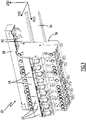
- the figure 1 shows an electrical panel 10 according to the invention.
- the electrical panel 10 is configured to be integrated into an electrical installation, for example equipping a building.
- the electrical panel 10 is in the form of a modular row.
- this modular row can be associated with other modular rows.
- the electrical panel 10 accommodates several electrical protection devices.
- the electrical panel 10 is modular, that is to say it is equipped with a variable number of electrical protection devices, depending on the needs of the electrical installation into which it is configured to be integrated, and that the Electrical protection devices can be of several types.
- electrical protection devices 12 of a first type and electrical protection devices 14 of a second type are shown.
- the electrical panel 10 further comprises a fixing rail 16, on which the electrical protection devices 12 and 14 are installed.
- the fixing rail 16 extends along an axis of width X10 of the electrical panel 10.
- the electrical protection devices 12 and 14 are juxtaposed along the axis of width X10.
- a depth axis Y10 and a height axis Z10 of the electrical panel 10 are also defined, which are perpendicular to each other and to the width axis X10.
- the height axis Z10 is vertical and directed upwards.
- the electrical panel 10 further comprises a supply comb 18, which extends along the axis of width X10, which is connected to all the electrical protection devices 12 and 14 and which supplies electrical energy to the electrical protection devices. , through connectors 20.
- the connectors 20 are divided into several groups, all the connectors of the same group being electrically connected to each other and electrically isolated from the connectors of the other groups.
- the supply comb 18 comprises four groups of connectors 20.
- three groups are each connected to a power supply phase of the electrical panel 10 and one group is connected to a neutral conductor of the electrical panel.
- the supply comb 18 comprises a different number of groups of connectors 20, for example two groups of connectors, respectively connected to a supply phase and to a neutral conductor.
- the supply comb 18 is arranged above the fixing rail 16, along the height axis Z10 of the electrical panel.
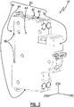
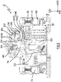
- the figures 2 to 12 show one of the electrical protection devices 12.
- the device 12 comprises a housing 30.
- a width direction X30, a depth direction Y30 and a height direction Z30 of the housing 30 are defined, which are mutually perpendicular and fixed with respect to the housing 30.
- the housing 30 constitutes an essentially closed and electrically insulating envelope.
- the box 30 advantageously comprises a front 32 and a back 34, distributed along the direction of depth Y30, with the front 32 in the direction Y30 with respect to the back 34.
- the device 12 is advantageously designed to be fixed on the fixing rail 16 via the casing 30.
- the device 12 advantageously comprises, on the back 34, any suitable fixing means, such as, for example, a snap-on clip 36, by means of which the device 12 can be fixedly attached to the rail 16, preferably by hand and without tools.
- any suitable fixing means such as, for example, a snap-on clip 36, by means of which the device 12 can be fixedly attached to the rail 16, preferably by hand and without tools.
- direction X30 is parallel to rail 16 and to axis X10
- direction Y30 is parallel to axis Y10
- direction Z30 is parallel to axis Z10.
- the back 34 of the casing 30 of the electrical protection device 12 is directed towards the rail 16 and the front 32 is opposite the rail 16.
- the housing 30 advantageously comprises a lower end 38 and an upper end 40 distributed along the direction Z30, with the upper end 40 in the direction Z30 with respect to the lower end 38, the upper end 40 being disposed above the lower end 38 in the mounted configuration of the device 12 on the electrical panel 10.
- the housing 30 advantageously comprises a right side 42 and a left side 44, preferably flat and parallel to each other, distributed along the direction X30, with the left side 44 in the direction X30 with respect to the right side, the left side 44 being arranged at left of the right side 42 in the mounted configuration of the device 12 on the electrical panel 10.
- the width of device 12, measured along direction X30 between left side 44 and right side 42, is between 15 mm and 25 mm, more preferably equal to 18 mm.
- the front 32 and the back 34 each connect the right side to the left side, in the direction X30.
- Each side connects the back 34 to the front 32, in the direction Y30.
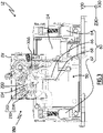
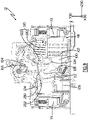
- the housing 30 comprises an internal partition 46 visible on the figures 3 to 10 , which extends parallel to the directions Y30 and Z30 and separates an internal volume of the housing 30 into a right compartment 48, visible on the figure 5 , 7 and 9 and in a left compartment 50, visible on the figure 3 , 4 , 6 , 8 and 10 .
- the right 48 and left 50 compartments are distributed along the direction X30.
- the right compartment 48 is delimited by the partition 46 and the right side 42 along the direction X30, by the ends 38 and 40 along the direction Z30, and by the front 32 and the back 34 along the direction Y30.
- the left compartment 50 is delimited by the partition 46 and the left side 44 in the direction X30, by the ends 38 and 40 in the direction Z30, and by the front 32 and the back 34 in the direction Y30.
- the electrical protection device 12 is a bipolar device, in that it comprises two conduction paths.
- each conduction path to comprise an input terminal, an output terminal, a movable contact and a fixed contact.
- a first conduction path 60 comprises an input terminal 62, an output terminal 64, a movable contact 66 and a fixed contact 68, visible on the figure 3 , 6 and 8
- a second conduction path 70 comprises an input terminal 72, an output terminal 74, a movable contact 76 and a fixed contact 78, visible on the figure 5 , 7 and 9 .
- conduction paths 60 and 70 are electrically isolated from each other.
- each conduction path is essentially, if not entirely, arranged in one of the respective compartments 48 or 50 of the housing 30.
- the first conduction path 60 is arranged in the left compartment 50 and the second conduction path 70 is disposed in the right compartment 48.
- the internal partition 46 is interposed between the paths 60 and 70, so as to ensure that they are electrically isolated from each other.
- the input terminals 62 and 72 are arranged at the upper end 40 of the casing 30, so as to be able to be electrically connected to the connectors 20 of the supply comb 18 belonging to the electrical panel 10.
- the input terminal 62 is connected to a first connector 20 belonging to a first group of connectors of the supply comb 18, while the input terminal 72 is connected to a second connector 20 belonging to a second group of power comb connectors 18.
- each input terminal 62 and 72 comprises a cavity 80, configured to accommodate a connector 20, and a screw 82, configured to tighten the connector 20 against the corresponding input terminal so as to establish electrical continuity between the connector 20 and the corresponding input terminal.
- the device 12 is connected to the supply comb 18 simply by plugging the connectors 20 of the comb into the input terminals 62 and 72 then tightening the screws 82.
- the input terminals 62 and 72, as well as the output terminals 64, 74, are screw terminals.
- the input terminals 62, 72 and/or the output terminals 64, 74 are automatic terminals, also called spade terminals, or quick connector terminals.
- Each conduction path 60 or 70 constitutes a separate pole of device 12.
- path 60 constitutes a neutral pole
- path 70 constitutes a phase pole.
- path 60 is connected to a neutral conductor of the electrical panel via a connector 20 and path 70 is connected to a power supply phase of the electrical panel via a connector 20.
- each conduction path is designed to be brought to a separate potential.
- the device 12 is designed to be used at a low voltage, that is to say a voltage between 100 V - Volts - and 600 V, for example a voltage of 240 V.
- the two conduction paths are phase conduction paths.
- the output terminals 64 and 74 are preferably arranged at the lower end 38 of the casing 30, so as to be able to be electrically connected to an electric circuit supplying receiving loads, for example, in the case of a building, household appliances or lighting. These electrical loads are then supplied with the electrical energy supplied to the input terminals 62 and 72 by the connectors 20 of the supply comb 18, through the device 12.
- the input terminal 62 of the conduction path connected to a neutral conductor of the electrical panel is arranged at the lower end 38 of the box 30, that is to say near the output terminals 64 and 74 , and the conduction path 60 forms a loop in the housing.
- three terminals are arranged at the lower end 38 of the case and only the input terminal 72 is arranged at the upper end 40 of the case.
- one of the three terminals is replaced by a plug-in clamp, or by an electric wire extending outside of the box 30.
- the fixed contact 68 is here fixed relative to the housing 30, and is electrically connected to the input terminal 62.
- the movable contact 66 is here electrically connected to the output terminal 64.
- the fixed contact 68 is arranged in the direction Z30 with respect to moving contact 66.
- the movable contact 66 preferably comprises a conductive end 90, providing the electrical contact function, and which is electrically connected to the output terminal 64.
- the movable contact 66 also comprises a contact carrier 92, which carries the end 90.
- the moving contact 66 is pivotable, relative to the housing 30, via the contact carrier 92, around a moving contact axis X66, parallel to the direction X30. This pivoting is performed between a position of conduction, shown on the figure 3 and 8 , and an isolation position, shown on the figure 6 .
- the conductive end 90 is in electrical contact with the fixed contact 68, which electrically connects the input terminal 62 to the output terminal 64.
- the end 90 of the movable contact 66 is moved away from the fixed contact 68, so as to be electrically isolated from it, which breaks the electrical connection between the terminals 62 and 64, so that the terminals 62 and 64 are electrically isolated from one of the 'other.
- Fixed contact 78 is fixed relative to housing 30, and is electrically connected to input terminal 72.
- Movable contact 76 is electrically connected to output terminal 74.
- Fixed contact 78 is disposed in direction Z30 relative to to the moving contact 76.
- the movable contact 76 preferably comprises a conductive end 94, providing the electrical contact function, and which is electrically connected to the output terminal 74.
- the movable contact 76 also comprises a contact carrier 96, which carries the end 94.
- the movable contact 76 is pivotable, relative to the housing 30, via the contact carrier 96, around a movable contact axis.
- the respective movable contact axes of the movable contacts 66 and 76 coincide, that is to say the movable contact 76 is pivotable around the same axis as the movable contact 66, in other words around the axis X66.
- the movable contact axes of the contacts 66 and 76 are mutually parallel, not coincident, and both parallel to the direction X30.
- the pivoting of the contact 76 is effected between a conduction position, shown on the figure 5 , and an isolated position, shown on the figure 7 .
- Movable contacts 66 and 76 are advantageously independently pivotable with respect to the housing. When they move from their respective conduction position to their respective isolation position, the moving contacts 66 and 76 advantageously rotate in the same direction around their respective moving contact axis, in the example around the axis X66. In particular, the contact ends 90 and 94 are then moved away from the direction Z30, that is to say towards the output terminals 64 and 74, i.e. towards the lower end 38 of the housing 30.
- the conductive end 94 is in electrical contact with the fixed contact 78, which electrically connects the input terminal 72 to the output terminal 74.
- the end 94 of moving contact 76 is moved away from fixed contact 78, so as to be electrically isolated therefrom, which breaks the electrical connection between terminals 72 and 74, so that terminals 72 and 74 are electrically isolated from each other.
- the movable contact 76 is shown in an intermediate position between the conduction and isolation positions, that is to say that the conductive end 94 is remote from the fixed contact 78 but the movable contact 76 is not in position of isolation. This intermediate position is obtained during the tilting of the movable contact 76 from its conduction position to its isolation position.
- the electrical protection device 12 comprises an interrupting chamber 100, which is shown complete on the figure 5 , and partially open on the figure 7 and 9 , to reveal its contents.
- the arcing chamber 100 aims to confer a breaking capacity to the device 12, by dissipating any electric arc which could occur when the movable contact 76 passes from the conduction position to the isolation position, that is to say when it moves away from the fixed contact 78.
- the interrupting chamber 100 is advantageously arranged in the right-hand compartment 48, between the fixed contact 78 and the input terminal 72, along the back 34 of the casing 30.
- the interrupting chamber 100 comprises for example a stack of metal plates 102, sometimes called fins or separators superimposed at a distance from each other, here along the direction Y30, to lengthen and thus extinguish any electric arc.
- the interrupting chamber 100 advantageously comprises insulating flanges, not shown, between which the plates 102 are arranged.
- the plates 102 are for example held between the internal partition 46 and the right side 42 of the casing 30.
- the input terminal 72 is interposed between the interrupting chamber 100 and the upper end 40 of the casing.
- the fixed contact 78 is preferably extended by an arcing horn 104, curved in the direction of the stack of metal plates 102 of the interrupting chamber 100.
- the interrupting chamber advantageously comprises an arcing horn 105, which is electrically connected to the conduction path 70, between the movable contact 76 and the output terminal 74.
- the arcing horn 105 is arranged opposite the arcing horn bow 104.
- any electric arc is conducted to the metal plates 102 via the arcing horns 104 and 105, to be divided and extinguished within the breaking chamber 100.
- the electrical protection device 12 further comprises at least one trip device.
- the protection device comprises three trip units 110, 112 and 114, each configured to be excited by an electrical fault of a distinct predetermined type and to switch the movable contacts 66 and 76 to the isolation position when they are excited.
- the trigger 110 visible on the figure 5 , 7 and 9 , is configured to be excited by an electrical fault of the short-circuit type which is, for example, likely to occur between the conduction paths 60 and 70 or between the conduction path 70 and ground.
- the trigger 110 is therefore in particular excited by a short-circuit which would occur downstream of the output terminals 64 and 74, on the electrical circuit supplied through the device 12, or on one of its loads. In this case, it is a phase-neutral or phase-earth short-circuit.
- the trigger 110 is placed in the right-hand compartment 48, and connected in series on the conduction path 70.
- the trigger 110 is placed between the input terminal 72 and the fixed contact 78.
- the trigger 110 is arranged between the interrupting chamber 100 and the front 32 of the housing 30.
- the trigger 110 is arranged between the right side 42 of the housing and the internal partition 46 of the housing.
- Trigger 110 is sometimes referred to as a magnetic trigger.
- the trigger 110 is in the form of a magnetic actuator, which here comprises an electromagnetic winding 120 and a mobile core 122.
- the core 122 is visible only on the figure 9 .
- the input terminal 72 is electrically connected to the fixed contact 78 via the trigger 110, in particular the electromagnetic winding 120.
- the intensity of the current flowing in the winding 120 suddenly becomes very high, so as to generate an electromagnetic force sufficient to move the mobile core 122 from a rest position, shown on the figure 5 and 7 , to a triggered position, shown on the figure 9 , relative to the housing 30.
- the movement of the core 122 from the rest position to the triggered position is carried out in a direction opposite to the direction Z30, that is to say towards the lower end 38 of the housing.
- the core 122 When the core 122 is moved to the tripped position, it causes the rotation of the movable contacts 66 and 76 from their conduction position to their isolation position, thus interrupting the flow of an electric current between the input terminals 62 and 72 and output terminals 64 and 74.
- the electrical protection device 12 is shown in a configuration where the trip device 110 is in the process of tripping, that is to say when the core 122 is in the tripped position.
- the movable contact 76 is no longer in the conduction position and has not yet reached the isolated position illustrated in figure 7 and the movable contact 66 has not yet left its conduction position.
- the trigger 112 visible on the figure 5 , 7 and 9 , is configured to be excited by an electrical fault of another predetermined type, namely an electrical fault of the overload type, which is, for example, liable to occur between the conduction paths 60 and 70.
- the trigger 112 is therefore in particular excited by an overload which would occur downstream of the output terminals 64 and 74, on the electrical circuit supplied through the device 12, or on one of its loads. This type of fault can occur when one or more loads connected to this electrical circuit impose an excessive current demand.
- the trigger 112 is arranged in the right compartment 48, and connected in series on the conduction path 70.
- the trigger 112 is arranged between the output terminal 74 and the movable contact 76.
- the trigger 112 is arranged between the back 34 and the front 32 of the case 30.
- the trigger 112 is arranged between the right side 42 of the case and the internal partition 46 of the case.
- Trigger 112 is sometimes referred to as a thermal trigger.
- the trigger 112 is in the form of a thermal actuator, which is here formed by an electrically conductive and heat-deformable bimetallic strip. When the bimetallic strip is crossed by an electric current, the bimetallic strip heats up by Joule effect and deforms.
- the movable contact 76 is electrically connected to the output terminal 74 via the trigger 112, that is to say here via the bimetallic strip.
- a flexible braid 124 electrically connects the movable contact 76 to the trip device 112.
- the intensity of the current flowing in the bimetallic strip forming the trip device 112 raises the temperature of the bimetallic strip until it causes its deformation. Once the fault ceases, the bimetallic strip cools and resumes its initial shape. The bimetallic strip is therefore mobile between an initial configuration and a deformed configuration.
- the bimetallic strip When the bimetallic strip is in the deformed configuration, it causes the rotation of the movable contacts 66 and 76 from their conduction position to their isolation position, thus interrupting the flow of an electric current between the input terminals 62 and 72 and the output terminals 64 and 74.
- Trip unit 114 is configured to be energized by an electrical fault of another predetermined type, namely a differential type electrical fault, which is likely to occur between conduction path 70 and ground.
- the trigger 114 is therefore in particular excited by a current leak to earth, which would occur downstream of the output terminals 64 and 74, then causing a difference between the value of the intensity of the current flowing within the conduction path 70 and the value of the intensity of the current flowing in the opposite direction within the conduction path 60.
- the differential sensor 126 detects a differential current, which is equal to a difference between the current flowing in the first conduction path 60 and the current flowing in the second conduction path 70.
- the trigger 114 extends both in the compartments 48 and 50, crossing the internal partition 46. In the direction Z30, the trigger 114 is advantageously arranged between on the one hand, the output terminals 64 and 74, and on the other hand, the fixed contacts 68 and 78 and the movable contacts 66 and 76.
- the trigger 114 is sometimes referred to as a differential trigger.
- trigger 114 includes a differential sensor 126, which extends into both compartments 48 and 50, being disposed along back 34 of housing 30.
- the trigger 114 also includes a relay 128, which extends only in the left compartment 50, being disposed between the front 32 and the differential sensor 126.
- the relay 128 is shown open to reveal the contents, according to an example.
- the relay 128 here comprises a plate 129, which pushes back a movable rod 130 when the relay 128 is actuated by the differential sensor 126.
- the differential sensor 126 comprises for example a ferromagnetic core, carrying two electromagnetic windings, one formed by the conduction path 60 and the other formed by the conduction path 70.
- the electromagnetic winding of the conduction path 60 is advantageously formed by a part of the path 60 between the moving contact 66 and the output terminal 64.
- the electromagnetic winding of the path 70 is advantageously formed by a part of the path 70 which connects the moving contact 76 to the output terminal 74, more precisely by part of path 70 between trigger 112 and output terminal 74.
- the movable contact 66 and the winding of the differential sensor 126 of the conduction path 60 are electrically connected using a braid, not shown.
- a difference in intensity is established between paths 60 and 70, beyond a certain threshold, an electromagnetic field is generated at the level of the toroid of the differential sensor 126.
- the differential sensor 126 is configured to generate electrical energy when the differential current is non-zero.
- the relay 128 is configured to be actuated when this electrical energy exceeds a certain threshold, which has the effect of releasing the plate 129 and actuating the movement of the movable rod 130 belonging to the relay 128, from a rest position, shown on the figure 3 and 8 , up to a trigger position, not visible in the figures, relative to the housing 30.
- the movement of the movable rod 130 from the rest position to the triggered position is carried out in the direction Z30, that is i.e. towards the upper end 40 of the housing 30.
- the movable rod 130 is shown in the reset position, in which the rod 130 is pushed back beyond the rest position, the rod 130 pushing back the plate 129 so as to reset the relay 128, which can move the rod again 130 from its rest position to its trip position as soon as a sufficiently large differential current occurs.
- the movable rod 130 When the movable rod 130 is moved from its rest position to its tripped position, it causes the rotation of the movable contacts 66 and 76 from their conduction position to their isolation position, thus interrupting the flow of an electric current between the input terminals 62 and 72 and output terminals 64 and 74.
- the electrical protection device 12 also includes a switching mechanism 150.
- Switch mechanism 150 is housed in housing 30, partly in compartment 48, and partly in compartment 50. Switch mechanism 150 is configured to switch between an armed configuration, shown in the figures 3 to 5 and 10 , in which the mechanism 150 puts the two movable contacts 66 and 76 in the conduction position, and a triggered configuration, shown on the figure 6 and 7 , wherein the switching mechanism 150 puts the movable contacts 66 and 76 in the isolated position.
- the switching mechanism 150 comprises a yoke 152, visible on the figures 3 to 10 .
- the stirrup 152 is pivotable with respect to the housing 30 around a stirrup axis X152, parallel to the movable contact axis X66.
- the stirrup 152 extends both in the compartments 48 and 50, being carried by the internal partition 46, straddling the latter.
- the yoke 152 When the mechanism 150 is in armed configuration, the yoke 152 is in a first orientation called “armed position” with respect to the housing 30, around the axis X152. When the mechanism 150 is in the triggered configuration, the yoke 152 is in a second orientation called the “triggered position”, around the axis X152. Mechanism 150 actuates movable contacts 66 and 76 via yoke 152.
- the stirrup 152 here comprises a plate 154, arranged in the left compartment 50, and a counter plate 156, placed in the right compartment 48.
- the plate 154 and the counter plate 156 are arranged either side of the internal partition 46 and are each pivoting about the caliper axis X152.
- the plate 154 and the counter-plate 156 are fixedly connected by a connecting shaft 158, so that any rotational movement of the plate 154 around the caliper axis X152 causes an identical rotational movement of the counter-plate 156 around caliper pin X152, and vice versa.
- the caliper axis X152 is also a plate axis 154, around which the plate 154 pivots.
- the plate 154 is said to be in the open position, respectively the closed position, when the stirrup 152 is in the armed position, respectively the triggered position.
- the plate 154 of the caliper 152 comprises for example a cam 160, disposed in the left compartment 50, via which the caliper 152 drives the movable contact 66 of the first conduction path 60 from the conduction position to 'in the isolation position, when the stirrup 152 is pivoted from the cocked position to the triggered position.
- the cam 160 bears against the contact carrier 92 of the movable contact 66.
- the plate 154 is configured for, when the plate 154 passes from its closed position open position, moving the first contact 66 from its conduction position to its isolation position.
- the switching mechanism 150 advantageously comprises a spring 162, called “contact spring”, which is arranged in the left compartment 50 while resting both on the plate 154 of the stirrup 152 and on the movable contact 66, more precisely on the contact holder 92.
- contact spring a spring 162, called "contact spring”
- spring 162 to apply a force to contact 66, bearing on plate 154, preferably on cam 160, which tends to press movable contact 66 against fixed contact 68, when yoke 152 is in the cocked position. This effort makes it possible to ensure satisfactory contact pressure between the movable contact 66 and the fixed contact 68.
- the counter-plate 156 of the caliper 152 comprises for example a cam 164, disposed in the right compartment 48, via which the caliper 152 drives the movable contact 76 of the second conduction path 70 from the position of conduction to the isolation position, when the stirrup 152 is pivoted from the armed position to the triggered position.
- the cam 164 bears against the contact carrier 96 of the movable contact 76.
- the switching mechanism 150 advantageously comprises a spring 166, called “contact spring”, which is arranged in the right-hand compartment 48 bearing both on the counter-plate 156 of the yoke 152 and on the movable contact 76, more precisely on the contact holder 96.
- contact spring a spring 166, called "contact spring”
- This force makes it possible to ensure satisfactory contact pressure between the movable contact 76 and the fixed contact 78.
- the contact springs 162 and 166 are helical torsion springs, mounted respectively on the movable contact 66 and on the movable contact 76 and of which a first branch bears respectively on the movable contact 66 and on the movable contact 76 and a second branch of which bears respectively on the cam 160 and on the cam 164.
- the cams 160 and 164 and that the contact springs 162 and 166 transmit a rotational movement of the yoke 152 into a rotational movement of the movable contacts 66 and 76, and that the direction of rotation of the movable contacts 66 and 76 is opposite to the direction of rotation of the stirrup 152.
- the stirrup switches from the armed position to the triggered position, it rotates clockwise, under the angle of the figure 3 and 4 , and rotates the movable contacts 66 and 76 counterclockwise, under the angle of the figure 3 and 4 .
- the switching mechanism 150 further comprises a spring 170, called “caliper spring”, visible on the figure 3 , 4 , 6 , 8 , 10 , 11 and 12 and shown alone with the 154 plate at figure 11 and 12 .
- the caliper spring 170 is here arranged in the left compartment 50 of the housing 30.
- the caliper spring 170 applies a force to the plate 154 of the caliper 152, bearing on the housing 30, which tends to move the caliper 152 from the cocked position to the triggered position.
- the stirrup spring 170 is a helical torsion spring, mounted on the internal partition 46, of which a first output branch 172 bears against the housing 30 and of which a second output branch 174 bears against a stop 176 belonging to the plate 154.
- the first branch 172 exerts a force F on the housing 30 and the second branch 174 exerts a force on the stop 176 of the plate 154.
- the force F exerted by the caliper spring 170 on the abutment 176 generates on the plate 154 a moment M, which causes the rotation of the plate 154 around the caliper axis X152 by a lever arm phenomenon.
- the force F exerted by the second branch 174 on the abutment 176 is directed along a straight line, denoted D176, which is perpendicular to the contact surface between the second branch and the abutment and which is located in a plane perpendicular to direction X152.
- the intensity of the moment M generated by the stirrup spring 170 on the plate 154 depends, on the one hand, on the intensity of the force F exerted by the second branch 174 on the stop 176 and, on the other hand , of the distance between the stirrup axis X152 and the straight line D176, denoted D and measured along an axis perpendicular to the straight line D176 and passing through the stirrup axis X152.
- D the greater this distance D, the greater the lever arm generating the moment M from the force F, because the moment M is equal to the product of the force F by the distance D.
- the stirrup 152 is configured so that, when the stirrup 152 is in the armed position, the distance D has a minimum value without however being zero, that is to say that the intensity of the moment M has a minimum value without be zero, while when the stirrup 152 is pivoted from the armed position to the triggered position, the distance D increases, that is to say that the intensity of the moment M increases.
- the increase in the moment M causing the pivoting of the stirrup 152 is advantageous, because it makes it possible to increase the speed of tilting of the movable contacts 66 and 76 between their conduction position and their isolation position.
- the electrical protection device 12 also includes a switching handle 190.
- the switching handle 190 is pivotable, relative to the housing 30, around a handle axis X190, parallel to the axis X30, between a closed position, shown on the figures 3 to 5 and 8 at 10 , and an open position, shown on the figure 6 and 7 .
- Switch handle 190 here includes a base 192, through which the handle is pivotally attached to housing 30.
- the base 192 is arranged through an opening belonging to the facade 32, closing this opening.
- the switching lever 190 is carried by the facade 32.
- the base 192 advantageously extends on either side of the internal partition 46.
- the lever 190 is advantageously centered, along the direction X30, on the facade 32.
- the switching lever 190 comprises a crankpin 194, carried by the base 192, and via which a user can actuate the lever 190 in rotation. To be accessible by the user, the crankpin 194 is arranged outside the housing 30.
- the switching mechanism 150 advantageously comprises a spring 196, called the "lever spring", visible on the figure 3 , 4 , 6 , 8 and 10 .
- the lever spring 196 applies a force to the lever 190 by bearing on the housing 30, which tends to bring the lever from the closed position to the open position.
- the lever spring 196 is a helical torsion spring, housed inside the base 192 around the lever axis X190, and of which one branch bears on the lever 190 and another branch bears on the internal partition 46.
- the switching mechanism 150 advantageously comprises a connecting rod 200, visible on the figure 3 , 4 , 6 , 8 and 10 .
- the connecting rod 200 is for example arranged in the left compartment 50.
- the connecting rod 200 comprises a first end 202 attached to the lever 190, in particular to the base 192. Via this first end 202, the connecting rod 200 can pivot with respect to the handle 190, around an axis which is parallel and not coincident with the axis of the handle X190. Thus, the rotation of the lever 190 is linked to a crank movement of the first end 202 of the connecting rod 200.
- the first end 202 of the connecting rod 200 describes an arc of a circle centered on the axis of the lever X190.
- Connecting rod 200 includes a second end 204, opposite first end 202, which interacts in particular with yoke 152, as described below.
- the second end 204 is guided in a groove 206 formed in the plate 154, that is to say in a plane parallel to the directions Y30 and Z30.
- the switching mechanism 150 advantageously includes a locking latch 210, visible on the figure 3 , 4 , 6 , 8 and 10 . At least a part of the locking latch 210 is arranged in the same compartment as that of the connecting rod 200, to cooperate with the latter, here the left compartment 50.
- At least a part of the locking latch 210 extends into the compartment or compartments where the triggers 110, 112 and 114 are housed, to cooperate mechanically with the latter, here the compartments 48 and 50.
- the latch 210 is advantageously carried by the yoke 152. Latch 210 transitions between a locking configuration, shown in the figures 3 to 5 and 10 , and an unlock configuration, shown on the figures 6 to 9 .
- each trigger 110, 112 and 114 is configured to switch the locking latch 210 from the locking configuration to the unlocking configuration, directly or indirectly, when said trigger 110, 112 or 114 concerned detects an electrical fault, of the type predetermined for this release.
- the latch 210 comprises a latch 212 and a hook 214 which cooperate together.
- hook 214 extends into both compartments 48 and 50, so as to be visible on the figures 3 to 10 .
- the hook 214 also extends into the compartment where the lock 212 is located, to cooperate with the latter.
- the hook 214 is carried by the stirrup 152, being pivotable with respect to the stirrup 152 around an axis X214, called “hook axis”, here parallel and not coincident with the axis of the stirrup X152. This pivoting is performed when the latch 210 moves between the locking and unlocking configurations.
- the hook 214 comprises a first part 216, placed in the same compartment as the lock 212, and a second part 218, placed in the other compartment.
- the first part 216 and second part 218 are fixedly connected to each other, preferably by being embedded one in the other, so that any movement of the first part 216 causes an identical movement of the second part 218, and vice versa.
- the lock 212 extends into the left compartment 50, so as to be visible on the figure 3 , 4 , 6 , 8 and 10 . In practice, it is expected that the lock 212 extends in the same compartment as that of the connecting rod 200, to cooperate with the latter.
- the lock 212 is carried by the stirrup 152, being pivotable with respect to the stirrup 152 around an axis X212, called the “lock axis”, here parallel and not coincident with the axis X152.
- the bolt axis X212 is carried by the connecting shaft 158 which connects the plate 154 to the counter-plate 156.
- a through hole 213 is made in the lock 212.
- the hook 214 In the locking configuration, the hook 214 is in a so-called “holding orientation”, where the hook 214 holds the lock 212 in a so-called “capture orientation”.
- the first part 216 of the hook 214 comprises for example a radial arm 220, against which the lock 212 comes into a rotational stop.
- the hook 214 In the unlocking configuration, the hook 214 is in a so-called “unhooking orientation”, where the hook 214 allows the lock 212 to be pivoted relative to the stirrup 152.
- the hook 214 Under the angle of the picture 3 , the hook 214 pivots clockwise to pass from the holding orientation to the unhooking orientation. When the hook 214 is moved from the unhooking orientation to the holding orientation, it returns and holds the latch 212 in the capture orientation.
- the hook 214 and the latch 212 are in contact, so that the latch 212 is prevented from rotating around the axis of the latch X212 by the hook 214, while in the unlocking configuration, the hook 214 and the latch 212 are not in contact, so that the latch 212 is not prevented from pivoting around the latch axis X212 by the hook 214.
- the minimum value of the moment M when the stirrup 152 is in the cocked position is advantageous, since the forces generated on the surfaces of the hook 214 and of the latch 212 in contact are also minimal.
- the force to be exerted on the hook 214 necessary to move the hook 214 from its holding orientation to its unhooking orientation is minimal.
- the latch 210 is particularly sensitive.
- the switching mechanism 150 advantageously comprises a spring 222, called the "latch spring", visible on the figure 5 , 7 and 9 .
- the latch spring 222 is provided in the right-hand compartment 48.
- the spring 222 applies a force to the locking latch 210, resting on the counter-plate 156 of the stirrup 152, which tends to bring the latch back lock 210 from the unlock configuration to the lock configuration.
- the spring 222 is a helical torsion spring, one branch of which rests on the counter-plate 156 and another branch of which rests on the second part 218 of the hook 214, so that the spring 222 actuates the latch 210 through the hook 214.
- the latch spring 222 tends to return the hook 214 from the unhooking orientation to the holding orientation.
- the second end 204 of the link 200 is captured by the locking latch 210, in particular by the latch 212, when the latch 210 is in the locking configuration, here when the latch 212 is in the capture orientation.
- the second end 204 of the connecting rod is arranged in the through hole 213 of the lock 212. Then, via the latch 210, the second end 204 is attached to the stirrup 152 while being pivotable relative to said stirrup 152 .
- the second end 204 of the connecting rod 200 is clamped between the walls of the groove 206 of the plate 154 and the walls of the through hole 213 of the lock 212 and cannot then move relative to plate 154 of stirrup 152 or relative to lock 212.
- the second end 204 of the connecting rod 200 is free to move in the groove 206 of the plate 154, and this movement causes the lock 212 to rotate around the lock axis X212.
- the position of the switching lever 190 is subject to the position of the yoke 152, and therefore to the position of the movable contacts 66 and 76, via the connecting rod 200 and the latch lock 210.
- the stirrup 152 is placed in the armed position, via the connecting rod 200, the second end of which 204 is captured by the latch 210 to drive the stirrup 152.
- the stirrup 152 being placed in the armed position, it puts the movable contacts 66 and 76 in the conduction position, via the contact springs 162 and 166.
- the stirrup 152 is put in the released position, by means of the connecting rod 200, the second end of which 204 is captured by the locking latch 210 to drive the caliper 152.
- the caliper being placed in the triggered position, it puts the contacts 66 and 76 in the isolated position, via the cams 160 and 164 of the plate 154 and counter plate 156.
- the yoke 152 When the locking latch 210 is in the locked configuration, the yoke 152 is in the armed position and the switch handle 190 is in the closed position, the yoke 152 and the switch handle 190 hold each other in position, meeting of the caliper spring 170, tending to move the caliper 152 to the tripped position, and the lever spring 196, tending to move the switching lever 190 to the open position.
- the connecting rod 200 is in the locking orientation when the first end 202 is positioned in a direction opposite to the direction Y30 with respect to a straight line, parallel to the directions Y30 and Z30 and crossing the axis of lever X190 and the second end 204.
- the rotation of the switching handle 190 from the closed position to the open position causes a movement of the first end 202, in a plane parallel to the directions Y30 and Z30, which describes an arc of a circle centered on the handle shaft X190.
- This movement in an arc of a circle leads to a displacement of the first end 202 in the direction opposite to the direction Z30, that is to say towards the lower end 38 of the housing, as long as the connecting rod 200 is in the orientation locking, then to a displacement of the first end 202 in the direction Z30 when the connecting rod 200 is no longer in the locking orientation, that is to say when the first end is positioned in the direction Y30 with respect to a straight, parallel to the directions Y30 and Z30 and crossing the joystick axis X190 and the second end 204.
- the displacement of the first end 202 in the direction opposite to the direction Z30 causes a displacement of the second end 204 in the same direction.
- the second end 204 exerts a force on the walls of the groove 206 of the plate 154 as well as a force on the walls of the through hole 213 of the lock 212.
- This force on the lock 212 tends to cause the lock 212 to rotate around of the bolt axis X212 clockwise, under the angle of the figure 3 and 4 , which tends to maintain the locking latch 210 in the locking configuration.
- the connecting rod 200 maintains the locking latch 210 in the locking configuration.
- the latch 212 and the yoke 152 are then prevented from rotating, which prevents the movement of the second end 204 in the direction opposite to the direction Z30 and which prevents the movement of the first end 202.
- the switch handle 190 is prevented from rotating.
- latch 210 is in the locking configuration and connecting rod 200 is in the locking orientation, yoke 152 is prevented from rotating.
- the switching lever 190 and the yoke 152 maintain each other in the closed position and in the cocked position, through connecting rod 200.
- the connecting rod When the user actuates a pivoting of the switch lever 190 towards the open position, the connecting rod is initially moved in the direction opposite to the direction Z30, as described above, and the actuation force provided by the user leads to exerting a force on the plate 154 which is sufficient to cause the rotation of the stirrup 152 in the counterclockwise direction, under the angle of the figure 3 and 4 , counter to the force exerted by the caliper spring 170.
- the connecting rod 200 is moved from its locking orientation until the first end 202 is positioned in the direction Y30 with respect to the right, parallel to the directions Y30 and Z30, which crosses the joystick shaft X190 and the second end 204.
- the locking latch releases the yoke 152 so that the yoke switches to the tripped position.
- the handle 190 places the switch mechanism 150 in the armed configuration.
- the handle 190 places the switch mechanism 150 in the tripped configuration.
- the direction of rotation of the switching lever 190 is identical to the direction of rotation of the yoke 152.
- the switching lever 190 is actuated towards the open position, that is to say say that the joystick rotates around the joystick axis X190 clockwise, under the angle of the figure 3 and 4 , then the caliper is swung into the triggered position by rotating around the caliper axis X152 clockwise, under the angle of the figure 3 and 4 .
- Each trigger 110, 112 and 114 is individually configured to trigger switching mechanism 150 to the triggered configuration, while switching mechanism 150 was in armed configuration, when said trigger 110, 112 or 114 is energized by the electrical fault of the predetermined type for this trigger 110, 112 or 114. This leads to a setting in the isolation position of the movable contacts 66 and 76 by the switching mechanism 150, when the electrical fault occurs.
- each trigger 110, 112 and 114 is designed to trigger a tilting of the locking latch 210 from the locking configuration to the unlocking configuration.
- the groove 206 of the plate 154 forms a non-branching path along which the second end 204 of the connecting rod 200 is allowed to move.
- the connecting rod 200 no longer operates a mutual maintenance in position of the stirrup 152 and the switching handle 190. Then, the handle 190 is returned to the open position under the action of the handle spring 196 and the yoke 152 is returned to the tripped position under the action of the yoke spring 170, the yoke 152 then driving the movable contacts 66 and 76 towards the isolated position.
- the switching mechanism 150 in particular the lever spring 196, to bring the switching lever 190 back to the open position when the switching mechanism 150 is placed in the triggered configuration, whether by action of the user on the switching lever 190 itself, or under the action of a trigger operated by one of the triggers 110, 112 or 114.
- the magnetic trigger 110 actuates, for example, a rocker 240 belonging to the switching mechanism 150, the rocker 240 driving the hook 214 to the unhooking position.
- Flip-flop 240 is visible on the figure 5 , 7 and 9 .
- the rocker 240 is attached to the casing 30, for example to the internal partition 46, being pivotable with respect to the casing 30 around a rocker axis X240 parallel to the caliper axis X152, between an initial position shown on the figure 5 and 7 , and a rocking position shown on the figure 9 .
- the magnetic trigger 110 drives the rocker 240 from the initial position to the rocking position by moving the movable core 122, which bears against a first end 242 of the rocker 240, here in a direction opposite to the direction Z30.
- the rocker 240 has a second end 244, which bears against a leg 246 belonging to the second part 218 of the hook 214, in the direction Z30, so that the hook 214 pivots to the unhooking orientation under the pivoting action of rocker 240 to the rocking position, against the force of latch spring 222.
- the mobile core 122 returns to its initial position, and allows the rocker 240 to be returned to the initial position, the rocker 240 thus allowing the hook 214 to be returned to the holding orientation.
- the rocker 240 is then returned to the initial position via the leg 246 of the second part 218 of the hook 214, while the hook 214 is itself returned to the holding orientation by latch spring 222.
- the moving contact 76 In addition, to allow faster switching of the moving contact 76 from its conduction position to its isolation position, when the moving core 122 is moved from its rest position to its triggered position, it also impacts the contact carrier. 96 of the movable contact 76. Thus, under the effect of the impact of the movable core 122, the movable contact 76 is moved directly into the isolated position, without waiting for the pivoting of the stirrup 152.
- the tilting of the movable contact 76 in the isolation position is faster than the tilting of the locking latch 210 into the unlocked position and than the tilting of the yoke 152 into the released position, so that when the yoke swings into the released position, it drives only the tilting of the movable contact 66 in the isolated position and also makes it possible to maintain the movable contact 76 in the isolated position, due to the action of the cam 164.
- FIG 8 This rapid switching of the movable contact 76 is illustrated in figure 8 and 9 , where the electrical protection device 12 is illustrated from two different angles at the same stage of the triggering of the magnetic trip device 110.
- figure 8 that the movable contact 66 is in contact with the fixed contact 68, whereas at the figure 9 , the movable contact 76 is not in contact with the fixed contact 78.
- the thermal trip device 112 to also actuate the rocker 240 from the initial position to the rocker position, here by means of a link 250, belonging to the switching mechanism 150.
- the rod 250 comprises a first end fixed to the bimetallic strip forming the trigger 112 and guided in translation in a pocket 252 formed in the internal partition 46 of the housing 30 and a second end fixed to the first end 242 of the rocker 240
- the deformation of the bimetallic strip under the effect of an electrical fault causes the link 250 to be moved in a direction opposite to the direction Z30, so that the latch 240 is driven from the initial position to the tilting position, as when the mobile core 122 of the magnetic trigger 120 comes to rest on the first end 242 of the rocker 240.
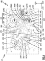
- the differential release 114 actuates, for example, a mechanical force amplifier 260, which is visible on the figure 3 , 4 , 6 and 8 , via the movable rod 130.
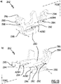
- the amplifier 260 comprises for example a drawer 262, a lock 264, a drawer spring 266, a lock spring 268 and a reset handle 270.
- Drawer 262 which is visible on the figure 13 , comprises a body 280 which extends along a drawer plane P280 orthogonal to the direction X30 when the protective device 12 is assembled.
- the drawer plane P280 is orthogonal to the direction of width X30, the movements of the drawer 262 being guided in the drawer plane P280.
- the drawer 262 is guided in translation relative to the box 30.
- the body 280 comprises for this purpose two oblong holes 282 and 284, which extend respectively along a guide axis A282 and A284, which are parallel between them.
- Each of the oblong holes 282 and 284 receives a rod belonging to the box 30, here connected to the internal partition 46, so as to guide the drawer 262 along one of the guide axes A282 or A284.
- the drawer 262 is here movable in translation relative to the box 30 along one of the guide axes A282 or A284.
- the drawer spring 266 is here a compression spring.
- the body 280 includes a bearing portion 286, configured to cooperate with the spool spring 266 so as to push the spool back towards its triggered position.
- the support portion 286 here comprises a distal face 288 and a centering pin 290.
- the distal face 288 is geometrically carried by a plane orthogonal to the guide axis X284, while the centering pin 290 is provided projecting on a central portion of the distal face 288 and serves to keep the spool spring 266 centered, to rest on the distal face 288.
- Slide spring 266 is configured to remain compressed regardless of the position of slide 262 and thus remain supported on distal face 288, contributing to the proper functioning of the mechanical force amplifier.
- the body 280 also includes a locking notch 292, a trigger stop 294, a first reset stop 296 and a second reset stop 298.
- Lock notch 292 configured to cooperate with latch 264 to hold spool 262 in the cocked position against spool spring 266.
- the trigger stop 294 comprises a thrust face 295, which here is oriented opposite the distal face 288 and which is configured to push back a leg 272, belonging to the first part 216 of the hook 214, when the drawer 262 is moves from the armed position to the triggered position.
- the first reset stop 296 is configured to cooperate with a protrusion 297 belonging to the contact carrier 92 of the first conduction path 60.
- the protuberance 297 presses on the first reset stop 296 and pushes the drawer 262 from its triggered position to its armed position.
- the second resetting abutment 298 here has the shape of a circular section cylinder centered on an axis orthogonal to the drawer plane P280.
- the second reset stop 298 is configured to push back the stand 270 when the drawer 262 is pushed back from its triggered position towards its armed position up to a reset position, located beyond the armed position, the armed position being a position intermediate between the reset position and the tripped position.
- the drawer 262 is configured to reset the trigger 114 by the intermediate stand 270.
- the drawer 262 is movable relative to the housing 30 between a cocked position, where the drawer 262 allows the locking latch 210 to be in the locking configuration, and a released position, where the drawer 262 puts the latch 210 in the unlocking configuration. In other words, in the triggered position the drawer 262 triggers a switchover of the switching mechanism 150 to the triggered configuration.
- the trigger stop 294 of the drawer 262 comes to bear, for example, against the leg 272 of the hook 214, when the drawer 262 is moved from the armed position to the triggered position, which drives the hook 214 from the orientation of Hold to stall orientation.
- Spool spring 266 applies a tripping force to spool 262, which tends to move the spool from the cocked position to the tripped position.
- the movable contact 66 passes from the conduction position to the isolation position, the movable contact 66 brings the drawer 262 back to the armed position, against the force of the drawer spring 266, by coming into support against drawer 262.
- the lock 264 here generally has an L-shape, with a support arm 265A, configured to be pushed back by the reset handle 270, and a blocking arm 265B.
- a support arm 265A configured to be pushed back by the reset handle 270
- a blocking arm 265B When the locking notch 292 cooperates with the lock 264, the locking arm 265B is wedged in the locking notch 292 and prevents movement of the drawer 262 from the armed position to the triggered position.
- the latch 264 is here pivotally mounted with respect to the housing 30, around a latch axis X264 parallel to the direction of width X30, between a locking position, shown on the figure 3 , 4 , 6 and 8 , where the lock 264 is opposite the locking notch 292 of the drawer 262, and an unlocking position, not visible in the figures, where the lock 264 allows the drawer 262 to be moved from the armed position to the position triggered by the spool spring 266, and to be returned from the triggered position to the armed position by the movable contact 66.
- the lock 264 bears against the locking notch and maintains the drawer 262 in the armed position, against the action of the drawer spring 266, while on the figure 6 , the lock 264 is located opposite the locking notch 292 but the drawer 262 being in its reset position, the lock 264 is not in contact with the locking notch 292. If the drawer 262 moves from the reset position to the armed position, which happens if a user moves the contacts 66 and 76 into the conduction position by actuating the switching lever 190, the plate 154 moves from the open position to the closed position, and the drawer 262, loaded by the drawer spring 266, comes into contact with the lock 264, which then maintains the drawer in the cocked position.
- the latch spring 268 exerts a locking force on the latch 264, resting on the internal partition 46 of the housing 30, which tends to bring the latch 264 from the unlocked position to the locked position.
- the reset handle 270 is carried by the housing 30, in particular on the internal partition 46, and extends between the lock 264 and the movable rod 130 of the trigger 114.
- the reset stand 270 is used to transmit the forces between, on the one hand, the movable rod 130 and, on the other hand, the lock 264 or the drawer 262, during certain of the operating phases of the electrical protection device 12
- the resetting lever 270 is for example made by means of a metal blade, which is preferably flexible, so as to guarantee the resetting of the relay 128 by absorbing the positioning dispersions of all the internal components of the relay 128.
- the resetting strut 270 is here pivotally mounted with respect to the housing 30 around a crutch axis X270 parallel to the direction of width X30, between a first so-called “resetting” position, shown on the figure 6 , in which the resetting handle 270 is pushed back by the drawer 262 and transmits a force to the rod 130, and a second position, not visible in the figures and called “unlocking position", in which the handle 270 transmits a force of the rod 130 to the lock 264 and causes the lock 264 in its unlocked position.
- the rod 130 pushes back the plate 129 so as to reset the relay 128.
- the handle 270 is shown in a so-called "neutral" position intermediate between the reset position and the unlocked position, in which the handle 270 does not transmit any force to the rod 130 or to the lock 264.
- the movable rod 130 When a differential fault occurs, the movable rod 130 is moved, here in the direction Z30. Under the action of the movement of the movable rod 130, the reset handle 270 is pivoted between the neutral position, shown on the figure 3 , 4 and 8 , and the unlocking position, not visible in the figures. In this pivoting, the stand 270 drives the lock 264 from its locking position to the unlocking position, against the action of the latch spring 268. The latch 264 being in the unlocked position, the spool 262 is allowed to be moved from the cocked position to the released position, under the action of the spool spring 266, and comes depress leg 272 of hook 214, which pivots hook 214 from the holding orientation to the unhooking orientation.
- drawer 262 switches locking latch 210 from the locking configuration to the unlocking configuration.
- the stirrup 152 switches the movable contacts 66 and 76 from the conduction position to the isolation position, by itself switching from the armed position to the triggered position.
- the contact carrier 92 of the contact 66 comes to bear against the drawer 262 so as to bring the drawer 262 back to the armed position, against the action of the drawer spring 266.
- the drawer 262 drives the reset handle 270 to the reset position. Therefore, the movable rod 130 is returned by the stand 270 to its reset position, so that the differential trip 114 is reset.
- the slide 262 During the displacement of the slide 262 towards the armed position, the slide 262 allows the lock 264 to be returned to the locking position by the lock spring 268, so that the lock 264 is facing the notch of drawer lock 262.
- the mechanical amplifier 260 and the differential trip device 114 have returned to their original configuration, to allow a new trip if a new fault occurs.
- the yoke 152 is in the tripped position, the movable contacts 66 and 76 are in the isolated position and the switch lever 190 is in the open position.
- the switching mechanism 150 described herein and its mode of triggering by triggers 110, 112 and 114 is given by way of illustrative example only.
- the magnetic trip device 110 and the thermal trip device 112 can be considered as a single trip device, then called a “magnetic thermal trip device", which causes the switching mechanism 150 to switch to the tripped configuration when an electrical fault of the short-circuit or overload type produced, by acting on the flip-flop 240.
- the fact that the yoke 152 rotates in a direction opposite to the movable contacts 66 and 76 makes it possible to position the magnetic trip device 110 in the upper part of the casing 30, in practice as close as possible to the upper end 40 of the casing.
- the positioning of the magnetic trip device is constrained by the direction of rotation of the movable contact 76, because the exit direction of the movable core 122 of the magnetic trip device must correspond to the direction of movement of the movable contact 76, the moving contact being driven by moving core 122 when magnetic trip device 110 is energized by an electrical fault.
- the trip device 114 is replaced by another functional component which is a trip device configured to be excited by an electrical fault of a predetermined type other than the aforementioned electrical faults, such as for example an electric arc occurring on a connected installation. to the output terminals 64 and 74, or even a trigger configured to be controlled by a communication system, for example to be triggered when an opening signal is communicated.
- a trip device configured to be excited by an electrical fault of a predetermined type other than the aforementioned electrical faults, such as for example an electric arc occurring on a connected installation.
- the trigger 114 is replaced by another functional component which is a monitoring system.
- a monitoring system is in practice a monitoring system configured to measure physical quantities representative of the operation of the protection device and/or to detect the operating state of the protection device and possibly configured to communicate information with a monitoring system. remote information. For example, such a monitoring system makes it possible to count the number of tilts of the stirrup 152 from the armed position to the triggered position.
- the drawer 262 is movable in translation with respect to the box 30 in the drawer plane P280, the drawer 262 being pushed back towards its triggered position by the drawer spring 266, which is a compression spring.
- the spool spring 266 is a tension spring, which returns the spool 262 to its triggered position.
- the drawer is rotatable relative to the box around an axis of rotation parallel to the axis of width X30.
- the drawer evolves in a plane of movement orthogonal to the axis of width X30.
- the drawer spring is either a compression spring, a tension spring, or even a torsion spring.
- the lock 264 is pivotally mounted relative to the box 30. In a variant not shown the lock 264 is carried by the drawer 262.
- the power amplifier device is functionally arranged between the differential trip device and the switching mechanism.
- the principle of the power amplifier can be transposed to other types of trip devices, in particular to the thermal trip device or magnetic trip device.
Landscapes
- Engineering & Computer Science (AREA)
- Power Engineering (AREA)
- Aviation & Aerospace Engineering (AREA)
- Physics & Mathematics (AREA)
- Electromagnetism (AREA)
- Switch Cases, Indication, And Locking (AREA)
- Patch Boards (AREA)
- Emergency Protection Circuit Devices (AREA)
- Gas-Insulated Switchgears (AREA)
- Breakers (AREA)
Applications Claiming Priority (1)
| Application Number | Priority Date | Filing Date | Title |
|---|---|---|---|
| FR2103123A FR3121272B1 (fr) | 2021-03-26 | 2021-03-26 | Dispositif de protection électrique et tableau électrique comprenant un tel dispositif de protection |
Publications (3)
| Publication Number | Publication Date |
|---|---|
| EP4064317A1 true EP4064317A1 (de) | 2022-09-28 |
| EP4064317B1 EP4064317B1 (de) | 2024-01-03 |
| EP4064317C0 EP4064317C0 (de) | 2024-01-03 |
Family
ID=75539663
Family Applications (1)
| Application Number | Title | Priority Date | Filing Date |
|---|---|---|---|
| EP22164267.1A Active EP4064317B1 (de) | 2021-03-26 | 2022-03-25 | Elektrische schutzvorrichtung und elektrische schalttafel mit einer solchen schutzvorrichtung |
Country Status (5)
| Country | Link |
|---|---|
| EP (1) | EP4064317B1 (de) |
| CN (1) | CN115132539A (de) |
| AU (1) | AU2022201980A1 (de) |
| ES (1) | ES2976767T3 (de) |
| FR (1) | FR3121272B1 (de) |
Families Citing this family (1)
| Publication number | Priority date | Publication date | Assignee | Title |
|---|---|---|---|---|
| FR3145060A1 (fr) | 2023-01-17 | 2024-07-19 | Schneider Electric Industries Sas | Dispositif de protection électrique et procédé de réarmement d’un tel dispositif |
Citations (4)
| Publication number | Priority date | Publication date | Assignee | Title |
|---|---|---|---|---|
| EP0570647A1 (de) * | 1992-05-13 | 1993-11-24 | Hager Electro S.A. | Schaltschloss für Schutzschalter und Schutzschalter, mit diesem integriert |
| EP0901142A1 (de) * | 1997-08-25 | 1999-03-10 | Schneider Electric Sa | Anzeigevorrichtung für elektrische fähler in eine Schaltvorrichtung, wie ein Differentialschutzschalter |
| EP1884976A1 (de) | 2006-08-01 | 2008-02-06 | Siemens Aktiengesellschaft | Schaltvorrichtung mit Betätigungselement |
| EP3451360A1 (de) | 2016-04-27 | 2019-03-06 | Yueqing Yewei Electric Co., Ltd | Beweglicher kontaktbetätigungsmechanismus eines fehlerstromschutzschalters |
-
2021
- 2021-03-26 FR FR2103123A patent/FR3121272B1/fr active Active
-
2022
- 2022-03-22 AU AU2022201980A patent/AU2022201980A1/en active Pending
- 2022-03-25 ES ES22164267T patent/ES2976767T3/es active Active
- 2022-03-25 CN CN202210305518.0A patent/CN115132539A/zh active Pending
- 2022-03-25 EP EP22164267.1A patent/EP4064317B1/de active Active
Patent Citations (4)
| Publication number | Priority date | Publication date | Assignee | Title |
|---|---|---|---|---|
| EP0570647A1 (de) * | 1992-05-13 | 1993-11-24 | Hager Electro S.A. | Schaltschloss für Schutzschalter und Schutzschalter, mit diesem integriert |
| EP0901142A1 (de) * | 1997-08-25 | 1999-03-10 | Schneider Electric Sa | Anzeigevorrichtung für elektrische fähler in eine Schaltvorrichtung, wie ein Differentialschutzschalter |
| EP1884976A1 (de) | 2006-08-01 | 2008-02-06 | Siemens Aktiengesellschaft | Schaltvorrichtung mit Betätigungselement |
| EP3451360A1 (de) | 2016-04-27 | 2019-03-06 | Yueqing Yewei Electric Co., Ltd | Beweglicher kontaktbetätigungsmechanismus eines fehlerstromschutzschalters |
Also Published As
| Publication number | Publication date |
|---|---|
| FR3121272A1 (fr) | 2022-09-30 |
| ES2976767T3 (es) | 2024-08-08 |
| AU2022201980A1 (en) | 2022-10-13 |
| CN115132539A (zh) | 2022-09-30 |
| EP4064317B1 (de) | 2024-01-03 |
| FR3121272B1 (fr) | 2023-03-31 |
| EP4064317C0 (de) | 2024-01-03 |
Similar Documents
| Publication | Publication Date | Title |
|---|---|---|
| EP0371887B1 (de) | Modulschützschalter mit Hilfsauslöseblock mit einer automatischen oder unabhängigen Wiedereinschaltung | |
| FR2638563A1 (fr) | Dispositif de securite pour appareil de commutation realise par l'assemblage de plusieurs elements modulaires amovibles | |
| EP2975628B1 (de) | Vorrichtung zur signalisierung einer elektrischen störung in einem elektrischen schutzgerät, und gerät, das eine solche vorrichtung umfasst | |
| FR2495825A1 (fr) | Disjoncteur multipolaire synchronise, constitue par plusieurs ensembles et comprenant une tige de liaison mutuelle | |
| FR2590723A1 (fr) | Interrupteur multipolaire commande par une horloge | |
| EP4064317B1 (de) | Elektrische schutzvorrichtung und elektrische schalttafel mit einer solchen schutzvorrichtung | |
| EP4064314B1 (de) | Elektrische schutzvorrichtung | |
| EP0571258B1 (de) | Schutzschaltgerät | |
| CH686853A5 (fr) | Appareil interrupteur de protection accouplable à un module de commande et/ou à un module de signalisation. | |
| EP4064313A1 (de) | Elektrische schutzvorrichtung und elektrischer schalttafel mit dieser elektrischen schutzvorrichtung | |
| WO2001069741A1 (fr) | Mecanisme extractible pour disjoncteurs | |
| EP4092711B1 (de) | Elektrische schutzvorrichtung | |
| EP4064318B1 (de) | Elektrische schutzvorrichtung | |
| EP4064316B1 (de) | Elektrische schutzvorrichtung und elektrische schalttafel mit einer solchen elektrischen schutzvorrichtung | |
| EP4138111B1 (de) | Elektrische schutzvorrichtung mit thermoauslöser, elektrische schalttafel mit einer solchen vorrichtung und verfahren zur regulierung einer solchen vorrichtung | |
| EP0310469B1 (de) | Schutzschalter mit Blende zum Unterbrechen des Lichtbogens | |
| EP2743958B1 (de) | Elektrisches Stromschaltgerät, insbesondere Abzweigschalter | |
| EP0602024B1 (de) | Betätigungsmechanismus für einen mehrpoligen Fehlerstromschutzschalter mit drehbarer Schaltwelle | |
| EP0136290B1 (de) | Schutzschalter mit sichtbarer trennung und handrückstellung | |
| WO2023194292A1 (fr) | Appareil de protection électrique modulaire avec modules de commande et de puissance | |
| FR3057389A1 (fr) | Appareillage de coupure electrique differentiel comportant un dispositif de test de la fonction differentielle |
Legal Events
| Date | Code | Title | Description |
|---|---|---|---|
| PUAI | Public reference made under article 153(3) epc to a published international application that has entered the european phase |
Free format text: ORIGINAL CODE: 0009012 |
|
| STAA | Information on the status of an ep patent application or granted ep patent |
Free format text: STATUS: THE APPLICATION HAS BEEN PUBLISHED |
|
| AK | Designated contracting states |
Kind code of ref document: A1 Designated state(s): AL AT BE BG CH CY CZ DE DK EE ES FI FR GB GR HR HU IE IS IT LI LT LU LV MC MK MT NL NO PL PT RO RS SE SI SK SM TR |
|
| STAA | Information on the status of an ep patent application or granted ep patent |
Free format text: STATUS: REQUEST FOR EXAMINATION WAS MADE |
|
| 17P | Request for examination filed |
Effective date: 20230228 |
|
| RBV | Designated contracting states (corrected) |
Designated state(s): AL AT BE BG CH CY CZ DE DK EE ES FI FR GB GR HR HU IE IS IT LI LT LU LV MC MK MT NL NO PL PT RO RS SE SI SK SM TR |
|
| RIC1 | Information provided on ipc code assigned before grant |
Ipc: H01H 83/22 20060101ALI20230626BHEP Ipc: H01H 71/52 20060101AFI20230626BHEP |
|
| GRAP | Despatch of communication of intention to grant a patent |
Free format text: ORIGINAL CODE: EPIDOSNIGR1 |
|
| STAA | Information on the status of an ep patent application or granted ep patent |
Free format text: STATUS: GRANT OF PATENT IS INTENDED |
|
| INTG | Intention to grant announced |
Effective date: 20230925 |
|
| GRAS | Grant fee paid |
Free format text: ORIGINAL CODE: EPIDOSNIGR3 |
|
| GRAA | (expected) grant |
Free format text: ORIGINAL CODE: 0009210 |
|
| STAA | Information on the status of an ep patent application or granted ep patent |
Free format text: STATUS: THE PATENT HAS BEEN GRANTED |
|
| AK | Designated contracting states |
Kind code of ref document: B1 Designated state(s): AL AT BE BG CH CY CZ DE DK EE ES FI FR GB GR HR HU IE IS IT LI LT LU LV MC MK MT NL NO PL PT RO RS SE SI SK SM TR |
|
| REG | Reference to a national code |
Ref country code: GB Ref legal event code: FG4D Free format text: NOT ENGLISH |
|
| REG | Reference to a national code |
Ref country code: CH Ref legal event code: EP |
|
| REG | Reference to a national code |
Ref country code: DE Ref legal event code: R096 Ref document number: 602022001508 Country of ref document: DE |
|
| REG | Reference to a national code |
Ref country code: IE Ref legal event code: FG4D Free format text: LANGUAGE OF EP DOCUMENT: FRENCH |
|
| U01 | Request for unitary effect filed |
Effective date: 20240112 |
|
| U07 | Unitary effect registered |
Designated state(s): AT BE BG DE DK EE FI FR IT LT LU LV MT NL PT SE SI Effective date: 20240123 |
|
| U20 | Renewal fee for the european patent with unitary effect paid |
Year of fee payment: 3 Effective date: 20240326 |
|
| PG25 | Lapsed in a contracting state [announced via postgrant information from national office to epo] |
Ref country code: IS Free format text: LAPSE BECAUSE OF FAILURE TO SUBMIT A TRANSLATION OF THE DESCRIPTION OR TO PAY THE FEE WITHIN THE PRESCRIBED TIME-LIMIT Effective date: 20240503 |
|
| PG25 | Lapsed in a contracting state [announced via postgrant information from national office to epo] |
Ref country code: GR Free format text: LAPSE BECAUSE OF FAILURE TO SUBMIT A TRANSLATION OF THE DESCRIPTION OR TO PAY THE FEE WITHIN THE PRESCRIBED TIME-LIMIT Effective date: 20240404 |
|
| PG25 | Lapsed in a contracting state [announced via postgrant information from national office to epo] |
Ref country code: HR Free format text: LAPSE BECAUSE OF FAILURE TO SUBMIT A TRANSLATION OF THE DESCRIPTION OR TO PAY THE FEE WITHIN THE PRESCRIBED TIME-LIMIT Effective date: 20240103 Ref country code: RS Free format text: LAPSE BECAUSE OF FAILURE TO SUBMIT A TRANSLATION OF THE DESCRIPTION OR TO PAY THE FEE WITHIN THE PRESCRIBED TIME-LIMIT Effective date: 20240403 |
|
| PG25 | Lapsed in a contracting state [announced via postgrant information from national office to epo] |
Ref country code: CZ Free format text: LAPSE BECAUSE OF FAILURE TO SUBMIT A TRANSLATION OF THE DESCRIPTION OR TO PAY THE FEE WITHIN THE PRESCRIBED TIME-LIMIT Effective date: 20240103 |
|
| PG25 | Lapsed in a contracting state [announced via postgrant information from national office to epo] |
Ref country code: RS Free format text: LAPSE BECAUSE OF FAILURE TO SUBMIT A TRANSLATION OF THE DESCRIPTION OR TO PAY THE FEE WITHIN THE PRESCRIBED TIME-LIMIT Effective date: 20240403 Ref country code: NO Free format text: LAPSE BECAUSE OF FAILURE TO SUBMIT A TRANSLATION OF THE DESCRIPTION OR TO PAY THE FEE WITHIN THE PRESCRIBED TIME-LIMIT Effective date: 20240403 Ref country code: IS Free format text: LAPSE BECAUSE OF FAILURE TO SUBMIT A TRANSLATION OF THE DESCRIPTION OR TO PAY THE FEE WITHIN THE PRESCRIBED TIME-LIMIT Effective date: 20240503 Ref country code: HR Free format text: LAPSE BECAUSE OF FAILURE TO SUBMIT A TRANSLATION OF THE DESCRIPTION OR TO PAY THE FEE WITHIN THE PRESCRIBED TIME-LIMIT Effective date: 20240103 Ref country code: GR Free format text: LAPSE BECAUSE OF FAILURE TO SUBMIT A TRANSLATION OF THE DESCRIPTION OR TO PAY THE FEE WITHIN THE PRESCRIBED TIME-LIMIT Effective date: 20240404 Ref country code: CZ Free format text: LAPSE BECAUSE OF FAILURE TO SUBMIT A TRANSLATION OF THE DESCRIPTION OR TO PAY THE FEE WITHIN THE PRESCRIBED TIME-LIMIT Effective date: 20240103 |
|
| PG25 | Lapsed in a contracting state [announced via postgrant information from national office to epo] |
Ref country code: PL Free format text: LAPSE BECAUSE OF FAILURE TO SUBMIT A TRANSLATION OF THE DESCRIPTION OR TO PAY THE FEE WITHIN THE PRESCRIBED TIME-LIMIT Effective date: 20240103 |
|
| REG | Reference to a national code |
Ref country code: ES Ref legal event code: FG2A Ref document number: 2976767 Country of ref document: ES Kind code of ref document: T3 Effective date: 20240808 |
|
| PG25 | Lapsed in a contracting state [announced via postgrant information from national office to epo] |
Ref country code: PL Free format text: LAPSE BECAUSE OF FAILURE TO SUBMIT A TRANSLATION OF THE DESCRIPTION OR TO PAY THE FEE WITHIN THE PRESCRIBED TIME-LIMIT Effective date: 20240103 |
|
| REG | Reference to a national code |
Ref country code: DE Ref legal event code: R097 Ref document number: 602022001508 Country of ref document: DE |
|
| PG25 | Lapsed in a contracting state [announced via postgrant information from national office to epo] |
Ref country code: SM Free format text: LAPSE BECAUSE OF FAILURE TO SUBMIT A TRANSLATION OF THE DESCRIPTION OR TO PAY THE FEE WITHIN THE PRESCRIBED TIME-LIMIT Effective date: 20240103 |
|
| PG25 | Lapsed in a contracting state [announced via postgrant information from national office to epo] |
Ref country code: SK Free format text: LAPSE BECAUSE OF FAILURE TO SUBMIT A TRANSLATION OF THE DESCRIPTION OR TO PAY THE FEE WITHIN THE PRESCRIBED TIME-LIMIT Effective date: 20240103 |
|
| PG25 | Lapsed in a contracting state [announced via postgrant information from national office to epo] |
Ref country code: SM Free format text: LAPSE BECAUSE OF FAILURE TO SUBMIT A TRANSLATION OF THE DESCRIPTION OR TO PAY THE FEE WITHIN THE PRESCRIBED TIME-LIMIT Effective date: 20240103 Ref country code: SK Free format text: LAPSE BECAUSE OF FAILURE TO SUBMIT A TRANSLATION OF THE DESCRIPTION OR TO PAY THE FEE WITHIN THE PRESCRIBED TIME-LIMIT Effective date: 20240103 Ref country code: RO Free format text: LAPSE BECAUSE OF FAILURE TO SUBMIT A TRANSLATION OF THE DESCRIPTION OR TO PAY THE FEE WITHIN THE PRESCRIBED TIME-LIMIT Effective date: 20240103 |
|
| PLBE | No opposition filed within time limit |
Free format text: ORIGINAL CODE: 0009261 |
|
| STAA | Information on the status of an ep patent application or granted ep patent |
Free format text: STATUS: NO OPPOSITION FILED WITHIN TIME LIMIT |
|
| PG25 | Lapsed in a contracting state [announced via postgrant information from national office to epo] |
Ref country code: MC Free format text: LAPSE BECAUSE OF FAILURE TO SUBMIT A TRANSLATION OF THE DESCRIPTION OR TO PAY THE FEE WITHIN THE PRESCRIBED TIME-LIMIT Effective date: 20240103 |
|
| PG25 | Lapsed in a contracting state [announced via postgrant information from national office to epo] |
Ref country code: MC Free format text: LAPSE BECAUSE OF FAILURE TO SUBMIT A TRANSLATION OF THE DESCRIPTION OR TO PAY THE FEE WITHIN THE PRESCRIBED TIME-LIMIT Effective date: 20240103 |
|
| 26N | No opposition filed |
Effective date: 20241007 |
|
| PG25 | Lapsed in a contracting state [announced via postgrant information from national office to epo] |
Ref country code: IE Free format text: LAPSE BECAUSE OF NON-PAYMENT OF DUE FEES Effective date: 20240325 |
|
| PG25 | Lapsed in a contracting state [announced via postgrant information from national office to epo] |
Ref country code: IE Free format text: LAPSE BECAUSE OF NON-PAYMENT OF DUE FEES Effective date: 20240325 |
|
| U20 | Renewal fee for the european patent with unitary effect paid |
Year of fee payment: 4 Effective date: 20250325 |
|
| PGFP | Annual fee paid to national office [announced via postgrant information from national office to epo] |
Ref country code: ES Payment date: 20250417 Year of fee payment: 4 |
|
| PG25 | Lapsed in a contracting state [announced via postgrant information from national office to epo] |
Ref country code: CY Free format text: LAPSE BECAUSE OF FAILURE TO SUBMIT A TRANSLATION OF THE DESCRIPTION OR TO PAY THE FEE WITHIN THE PRESCRIBED TIME-LIMIT; INVALID AB INITIO Effective date: 20220325 |
|
| REG | Reference to a national code |
Ref country code: CH Ref legal event code: H13 Free format text: ST27 STATUS EVENT CODE: U-0-0-H10-H13 (AS PROVIDED BY THE NATIONAL OFFICE) Effective date: 20251023 |
|
| PG25 | Lapsed in a contracting state [announced via postgrant information from national office to epo] |
Ref country code: TR Free format text: LAPSE BECAUSE OF FAILURE TO SUBMIT A TRANSLATION OF THE DESCRIPTION OR TO PAY THE FEE WITHIN THE PRESCRIBED TIME-LIMIT Effective date: 20240103 |
|
| PG25 | Lapsed in a contracting state [announced via postgrant information from national office to epo] |
Ref country code: CH Free format text: LAPSE BECAUSE OF NON-PAYMENT OF DUE FEES Effective date: 20250331 |
|
| PGFP | Annual fee paid to national office [announced via postgrant information from national office to epo] |
Ref country code: GB Payment date: 20260324 Year of fee payment: 5 |