EP4064299A1 - Widerstandsplattenanordnung mit kontaktbändern - Google Patents
Widerstandsplattenanordnung mit kontaktbändern Download PDFInfo
- Publication number
- EP4064299A1 EP4064299A1 EP22161401.9A EP22161401A EP4064299A1 EP 4064299 A1 EP4064299 A1 EP 4064299A1 EP 22161401 A EP22161401 A EP 22161401A EP 4064299 A1 EP4064299 A1 EP 4064299A1
- Authority
- EP
- European Patent Office
- Prior art keywords
- assembly
- resistor
- recited
- resistor plate
- pin
- Prior art date
- Legal status (The legal status is an assumption and is not a legal conclusion. Google has not performed a legal analysis and makes no representation as to the accuracy of the status listed.)
- Pending
Links
Images

Classifications
-
- H—ELECTRICITY
- H01—ELECTRIC ELEMENTS
- H01C—RESISTORS
- H01C10/00—Adjustable resistors
- H01C10/50—Adjustable resistors structurally combined with switching arrangements
-
- H—ELECTRICITY
- H01—ELECTRIC ELEMENTS
- H01C—RESISTORS
- H01C1/00—Details
- H01C1/01—Mounting; Supporting
-
- H—ELECTRICITY
- H01—ELECTRIC ELEMENTS
- H01C—RESISTORS
- H01C1/00—Details
- H01C1/14—Terminals or tapping points specially adapted for resistors; Arrangements of terminals or tapping points on resistors
-
- H—ELECTRICITY
- H01—ELECTRIC ELEMENTS
- H01C—RESISTORS
- H01C10/00—Adjustable resistors
- H01C10/46—Arrangements of fixed resistors with intervening connectors, e.g. taps
- H01C10/48—Arrangements of fixed resistors with intervening connectors, e.g. taps including contact movable in an arcuate path
-
- H—ELECTRICITY
- H02—GENERATION; CONVERSION OR DISTRIBUTION OF ELECTRIC POWER
- H02K—DYNAMO-ELECTRIC MACHINES
- H02K11/00—Structural association of dynamo-electric machines with electric components or with devices for shielding, monitoring or protection
- H02K11/04—Structural association of dynamo-electric machines with electric components or with devices for shielding, monitoring or protection for rectification
- H02K11/042—Rectifiers associated with rotating parts, e.g. rotor cores or rotary shafts
-
- H—ELECTRICITY
- H02—GENERATION; CONVERSION OR DISTRIBUTION OF ELECTRIC POWER
- H02K—DYNAMO-ELECTRIC MACHINES
- H02K19/00—Synchronous motors or generators
- H02K19/16—Synchronous generators
- H02K19/36—Structural association of synchronous generators with auxiliary electric devices influencing the characteristic of the generator or controlling the generator, e.g. with impedances or switches
-
- H—ELECTRICITY
- H01—ELECTRIC ELEMENTS
- H01C—RESISTORS
- H01C10/00—Adjustable resistors
- H01C10/46—Arrangements of fixed resistors with intervening connectors, e.g. taps
-
- H—ELECTRICITY
- H01—ELECTRIC ELEMENTS
- H01C—RESISTORS
- H01C13/00—Resistors not provided for elsewhere
- H01C13/02—Structural combinations of resistors
Definitions
- This disclosure relates generally to electrical machines and more particularly to resistor plates for generators.
- variable frequency generator there is a resistor assembly that is mounted in the rotor shaft.
- the resistor plate assembly can include two resistor pin bores/pin connections and serves two functions in the rotor balance assembly. First, the resistor plate assembly connects the positive direct current (DC) pin from the rotating resistor assembly to the resistor package and subsequently the main field. Second, the resistor plate assembly completes the circuit for the positive and negative rails of the rotating rectifier assembly through the suppression resistor.
- Traditional resistor plate assemblies are made from beryllium copper (BeCu) which can be a health hazard when machined.
- An assembly comprises a resistor plate for a rotating rectifier assembly (RRA).
- RRA rotating rectifier assembly
- a shaft bore is defined through the resistor plate for passage of a shaft of an electrical machine, and the resistor plate defines a main annular body around the shaft bore.
- At least one coolant channel can be defined in the main annular body of the resistor plate.
- a first protrusion extends radially outward from the main annular body, so that a first pin bore extends through the first protrusion.
- At least one contact band is seated in a the pin bore of the resistor plate for mounting a direct current (DC) pin to the resistor plate.
- DC direct current
- a respective joining interface can be formed between each of the at least one contact bands and the resistor plate, and the joining interface can be free of braze.
- Each respective joining interface of the at least one contact bands can be an interference fit.
- the at least one contact band can include a first contact band and a second contact band wherein the first contact band is axially stacked with the second contact band within the pin bore.
- the contact bands can be spring type contact bands.
- the assembly can further include a DC pin seated in the at least one contact band.
- the resistor plate can be of Aluminum, the at least one contact band can be of a metallic material, and the assembly can be free of Beryllium Copper (BeCu).
- the assembly can further include, a second protrusion extending radially outward from the main annular body, wherein a second pin bore extends through the second protrusion. At least one contact band can be seated in a the second pin bore of the second protrusion, and a second DC pin can be seated in the at least one contact band of the second protrusion.
- a resistor cover can be stacked axially with the resistor plate, and a resistor support assembly stacked axially with the resistor plate and the resistor cover, such that the resistor plate can be sandwiched between the resistor cover and the resistor support assembly.
- the resistor cover and the resistor support assembly can further include at least one axial channel defined therein for accommodating another DC pin.
- the resistor plate can be assembled into the RRA of a variable frequency generator (VFG).
- the first and second DC pins can electrically connect between diodes and a field winding of the VFG for rectifying alternating current (AC) to DC in the RRA.
- the resistor plate can be the only resistor plate in the VFG.
- FIG. 1 a partial view of an embodiment of an assembly in accordance with the disclosure is shown in Fig. 1 and is designated generally by reference character 100.
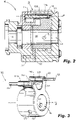
- FIGs. 2-3 Other embodiments of systems in accordance with the disclosure, or aspects thereof, are provided in Figs. 2-3 , as will be described.
- the systems and methods described herein can be used to improve electrical and thermal conductivity within in a generator.
- an assembly 100 can include a resistor plate 102 for a rotating rectifier assembly (RRA) 10 which can be mounted in a generator 1 (e.g. a brushless and/or variable frequency generator (VFG)).
- the resistor plate 102 can be the only resistor plate in the VFG 1.
- a shaft bore 104 can be defined through the resistor plate 102 for passage of a shaft 106 of an electrical machine (e.g. generator 1), and for passage of cooling oil through the generator 1.
- the resistor plate 102 can define a main annular body 108 around the shaft bore 104. At least one coolant channel 170 can be defined in the main annular body 108 of the resistor plate 102.
- a first protrusion 110 can extend radially outward from the main annular body 108, so that a first pin bore 112 can extend axially through the first protrusion 110 (e.g. along axis A, parallel to the shaft bore 104).
- the resistor plate 102 can be of Aluminum, however any suitable conductive material can be used.
- At least one contact band 114 can be seated in a the first pin bore 112 of the resistor plate 102 for mounting a direct current (DC) pin 116 to the mounting ring 102.
- the at least one contact band 114 can allow for precise, durable positioning of the DC pin 116 within the resistor plate 102.
- the at least one contact band 114 can be of a metallic material, for example a material that allows the DC pin 116 to electrically connect between diodes 140 and a field winding 150 of the VFG 1 for rectifying alternating current (AC) to DC in the RRA 10 (e.g. as shown in Fig. 1 ).
- Both the resistor plate 102 and at least one contact band 114 can be free of BeCu, however it is contemplated that the entire assembly 100 as described herein can be free of BeCu.
- respective joining interface 118 can be formed between each of the at least one contact bands 114 and the resistor plate 102, Brazing the DC pin 116 to the resistor plate 102 can weaken the assembly 100, therefore the joining interface 118 can be free of braze.
- Each respective joining interface 118 of the at least one contact band 114 can be an interference fit, for example, the at least one contact band 114 can be spring type contact band.
- the at least one contact band 114 can include a first contact band 114a and a second contact band 114b. The first contact band 114a can be axially stacked with the second contact band 114b within the pin bore 112.
- the assembly 100 can further include, a second protrusion 120 extending radially outward from the main annular body 108, wherein a second pin bore 122 extends through the second protrusion 120.
- At least one contact band 124a,b can be seated in a the second pin bore 122 of the second protrusion 120, and a second DC pin 126 can be seated in the at least one contact band 124 of the second protrusion 120.
- a resistor cover 128 can be stacked axially with the resistor plate 102, and a resistor support assembly 130 can be stacked axially with the resistor plate and the resistor cover. As shown in Fig. 2 , the resistor plate 102 can be sandwiched between the resistor cover 128 and the resistor support assembly 130.
- the resistor cover and the resistor support assembly can both have at least one pin bore 132 defined therein for accommodating another DC pin (not shown).
- the pin bore 132 can also have at least one contact band 134 seated therein, where contact band 134 is the same or substantially similar to contact bands 114 and 124 described above.
- the at least one pin bore 132 can provide connection points for DC pins connecting from the diodes 140 in a diode package to mate with the resistor assembly 10.
Landscapes
- Engineering & Computer Science (AREA)
- Power Engineering (AREA)
- Microelectronics & Electronic Packaging (AREA)
Applications Claiming Priority (1)
| Application Number | Priority Date | Filing Date | Title |
|---|---|---|---|
| US17/200,824 US11949294B2 (en) | 2021-03-13 | 2021-03-13 | Resistor plate assembly with contact bands |
Publications (1)
| Publication Number | Publication Date |
|---|---|
| EP4064299A1 true EP4064299A1 (de) | 2022-09-28 |
Family
ID=80735627
Family Applications (1)
| Application Number | Title | Priority Date | Filing Date |
|---|---|---|---|
| EP22161401.9A Pending EP4064299A1 (de) | 2021-03-13 | 2022-03-10 | Widerstandsplattenanordnung mit kontaktbändern |
Country Status (2)
| Country | Link |
|---|---|
| US (1) | US11949294B2 (de) |
| EP (1) | EP4064299A1 (de) |
Citations (3)
| Publication number | Priority date | Publication date | Assignee | Title |
|---|---|---|---|---|
| US20130300231A1 (en) * | 2012-05-08 | 2013-11-14 | Hamilton Sundstrand Corporation | Rotating resistor assembly |
| EP2773031A2 (de) * | 2013-03-01 | 2014-09-03 | Hamilton Sundstrand Corporation | Verbinder und Federanordnung für einen Generator |
| EP3758201A1 (de) * | 2019-06-28 | 2020-12-30 | Hamilton Sundstrand Corporation | Hochgeschwindigkeitsgeneratorverbindungsanordnung |
Family Cites Families (14)
| Publication number | Priority date | Publication date | Assignee | Title |
|---|---|---|---|---|
| US4492887A (en) | 1983-08-25 | 1985-01-08 | Sundstrand Corporation | Compact resistor assembly for rotary electric machine |
| US5219617A (en) | 1989-09-19 | 1993-06-15 | Michigan Chrome And Chemical Company | Corrosion resistant coated articles and process for making same |
| JP2679499B2 (ja) | 1991-12-27 | 1997-11-19 | 三菱電機株式会社 | 遮断器及び開閉部の操作機構 |
| US20080218035A1 (en) | 2007-03-09 | 2008-09-11 | C.E. Niehoff & Co. | Rotating rectifier assembly |
| US8063522B2 (en) | 2009-09-14 | 2011-11-22 | Hamilton Sundstrand Corporation | Generator rotor ground bushing |
| US9474189B2 (en) | 2012-05-23 | 2016-10-18 | Mitsubishi Electric Corporation | Inverter device |
| US20140226383A1 (en) * | 2013-02-11 | 2014-08-14 | Hamilton Sundstrand Corporation | Coaxial rotating rectifier package assembly for generator |
| US9461526B2 (en) * | 2014-01-03 | 2016-10-04 | Hamilton Sundstrand Corporation | Grounded radial diode pack |
| US9912213B2 (en) | 2015-02-02 | 2018-03-06 | Hamilton Sundstrand Corporation | Rotating rectifiers with nested diodes |
| US11139723B2 (en) | 2017-04-28 | 2021-10-05 | Hamilton Sundstrand Corporation | Rotating rectifier assembly |
| EP3587832B1 (de) | 2018-06-24 | 2024-04-03 | Hamilton Sundstrand Corporation | Servoventilgehäuse |
| US10460861B1 (en) * | 2018-10-29 | 2019-10-29 | Hamilton Sundstrand Corporation | High speed rotor connection assembly |
| TWI679830B (zh) | 2019-01-04 | 2019-12-11 | 建準電機工業股份有限公司 | 馬達及具有該馬達之吊扇 |
| US10879772B2 (en) | 2019-01-08 | 2020-12-29 | Hamilton Sundstrand Corporation | Rotating resistor assemblies |
-
2021
- 2021-03-13 US US17/200,824 patent/US11949294B2/en active Active
-
2022
- 2022-03-10 EP EP22161401.9A patent/EP4064299A1/de active Pending
Patent Citations (3)
| Publication number | Priority date | Publication date | Assignee | Title |
|---|---|---|---|---|
| US20130300231A1 (en) * | 2012-05-08 | 2013-11-14 | Hamilton Sundstrand Corporation | Rotating resistor assembly |
| EP2773031A2 (de) * | 2013-03-01 | 2014-09-03 | Hamilton Sundstrand Corporation | Verbinder und Federanordnung für einen Generator |
| EP3758201A1 (de) * | 2019-06-28 | 2020-12-30 | Hamilton Sundstrand Corporation | Hochgeschwindigkeitsgeneratorverbindungsanordnung |
Also Published As
| Publication number | Publication date |
|---|---|
| US11949294B2 (en) | 2024-04-02 |
| US20220294316A1 (en) | 2022-09-15 |
Similar Documents
| Publication | Publication Date | Title |
|---|---|---|
| US7868494B2 (en) | Rectifier assembly | |
| US6570289B1 (en) | Low noise automotive alternator | |
| US11139723B2 (en) | Rotating rectifier assembly | |
| EP2773031B1 (de) | Verbinder und Federanordnung für einen Generator | |
| EP2793374B1 (de) | Anschlussanordnung für Elektromaschine | |
| JPS5886835A (ja) | 回転電機 | |
| JPS62501048A (ja) | 整流器組立体 | |
| US4959707A (en) | Rotating rectifier assembly | |
| EP1386384B1 (de) | Schneller multipolgenerator mit modularer gleichrichterschaltung | |
| EP3681020B1 (de) | Rotierende widerstandsanordnungen | |
| US8890379B2 (en) | Rotating rectifier assembly and method | |
| US11949294B2 (en) | Resistor plate assembly with contact bands | |
| US20040174081A1 (en) | Diode interconnection in an alternator rectifier | |
| GB2256745A (en) | Reduced length rotating rectifier assembly | |
| US11799391B2 (en) | Diode mounting ring with contact band inserts | |
| CN107041164A (zh) | 车用交流发电机 | |
| CN103944299B (zh) | 用于连接电机定子绕组的相绕组导线的方法以及电机 | |
| DE2819824C2 (de) | ||
| EP4068592A1 (de) | Widerstandsstützvorrichtung mit federsitz | |
| US11051433B2 (en) | Rectifier of rotating electric machine | |
| US20040256925A1 (en) | Rectifier for a vehicle alternator | |
| US11735980B2 (en) | Anti-rotation feature for bonded stud | |
| EP0154630B1 (de) | Kompaktwiderstandseinheit für elektrische drehmaschinen | |
| JP2001286104A (ja) | 回転電機 | |
| JP2013005585A (ja) | 整流子、整流子を備えた回転子及び、整流子を備えた回転子の製造方法 |
Legal Events
| Date | Code | Title | Description |
|---|---|---|---|
| PUAI | Public reference made under article 153(3) epc to a published international application that has entered the european phase |
Free format text: ORIGINAL CODE: 0009012 |
|
| STAA | Information on the status of an ep patent application or granted ep patent |
Free format text: STATUS: THE APPLICATION HAS BEEN PUBLISHED |
|
| AK | Designated contracting states |
Kind code of ref document: A1 Designated state(s): AL AT BE BG CH CY CZ DE DK EE ES FI FR GB GR HR HU IE IS IT LI LT LU LV MC MK MT NL NO PL PT RO RS SE SI SK SM TR |
|
| STAA | Information on the status of an ep patent application or granted ep patent |
Free format text: STATUS: REQUEST FOR EXAMINATION WAS MADE |
|
| 17P | Request for examination filed |
Effective date: 20230328 |
|
| RBV | Designated contracting states (corrected) |
Designated state(s): AL AT BE BG CH CY CZ DE DK EE ES FI FR GB GR HR HU IE IS IT LI LT LU LV MC MK MT NL NO PL PT RO RS SE SI SK SM TR |