EP4063779B1 - Wärmetauscherstifte - Google Patents
Wärmetauscherstifte Download PDFInfo
- Publication number
- EP4063779B1 EP4063779B1 EP21461527.0A EP21461527A EP4063779B1 EP 4063779 B1 EP4063779 B1 EP 4063779B1 EP 21461527 A EP21461527 A EP 21461527A EP 4063779 B1 EP4063779 B1 EP 4063779B1
- Authority
- EP
- European Patent Office
- Prior art keywords
- pin
- pins
- layer
- sub
- section
- Prior art date
- Legal status (The legal status is an assumption and is not a legal conclusion. Google has not performed a legal analysis and makes no representation as to the accuracy of the status listed.)
- Active
Links
- 239000012530 fluid Substances 0.000 claims description 75
- 238000004519 manufacturing process Methods 0.000 claims description 49
- 238000000034 method Methods 0.000 claims description 21
- 239000000843 powder Substances 0.000 claims description 14
- 239000000654 additive Substances 0.000 claims description 13
- 230000000996 additive effect Effects 0.000 claims description 13
- 229910052751 metal Inorganic materials 0.000 claims description 9
- 239000002184 metal Substances 0.000 claims description 9
- 238000000926 separation method Methods 0.000 claims description 6
- 229910000838 Al alloy Inorganic materials 0.000 claims description 5
- 229910000881 Cu alloy Inorganic materials 0.000 claims description 5
- 229910018487 Ni—Cr Inorganic materials 0.000 claims description 5
- VNNRSPGTAMTISX-UHFFFAOYSA-N chromium nickel Chemical compound [Cr].[Ni] VNNRSPGTAMTISX-UHFFFAOYSA-N 0.000 claims description 5
- 229910000601 superalloy Inorganic materials 0.000 claims description 5
- 239000000463 material Substances 0.000 description 6
- CURLTUGMZLYLDI-UHFFFAOYSA-N Carbon dioxide Chemical compound O=C=O CURLTUGMZLYLDI-UHFFFAOYSA-N 0.000 description 4
- 238000010276 construction Methods 0.000 description 3
- 230000003466 anti-cipated effect Effects 0.000 description 2
- 229910002092 carbon dioxide Inorganic materials 0.000 description 2
- 150000002739 metals Chemical class 0.000 description 2
- XLYOFNOQVPJJNP-UHFFFAOYSA-N water Substances O XLYOFNOQVPJJNP-UHFFFAOYSA-N 0.000 description 2
- 239000003570 air Substances 0.000 description 1
- 239000001569 carbon dioxide Substances 0.000 description 1
- 238000005260 corrosion Methods 0.000 description 1
- 230000007797 corrosion Effects 0.000 description 1
- 238000005516 engineering process Methods 0.000 description 1
- 229910001026 inconel Inorganic materials 0.000 description 1
- 239000007788 liquid Substances 0.000 description 1
- 239000000203 mixture Substances 0.000 description 1
- 238000011084 recovery Methods 0.000 description 1
Images


Classifications
-
- F—MECHANICAL ENGINEERING; LIGHTING; HEATING; WEAPONS; BLASTING
- F28—HEAT EXCHANGE IN GENERAL
- F28F—DETAILS OF HEAT-EXCHANGE AND HEAT-TRANSFER APPARATUS, OF GENERAL APPLICATION
- F28F3/00—Plate-like or laminated elements; Assemblies of plate-like or laminated elements
- F28F3/02—Elements or assemblies thereof with means for increasing heat-transfer area, e.g. with fins, with recesses, with corrugations
- F28F3/022—Elements or assemblies thereof with means for increasing heat-transfer area, e.g. with fins, with recesses, with corrugations the means being wires or pins
-
- B—PERFORMING OPERATIONS; TRANSPORTING
- B22—CASTING; POWDER METALLURGY
- B22F—WORKING METALLIC POWDER; MANUFACTURE OF ARTICLES FROM METALLIC POWDER; MAKING METALLIC POWDER; APPARATUS OR DEVICES SPECIALLY ADAPTED FOR METALLIC POWDER
- B22F10/00—Additive manufacturing of workpieces or articles from metallic powder
- B22F10/20—Direct sintering or melting
- B22F10/28—Powder bed fusion, e.g. selective laser melting [SLM] or electron beam melting [EBM]
-
- B—PERFORMING OPERATIONS; TRANSPORTING
- B33—ADDITIVE MANUFACTURING TECHNOLOGY
- B33Y—ADDITIVE MANUFACTURING, i.e. MANUFACTURING OF THREE-DIMENSIONAL [3-D] OBJECTS BY ADDITIVE DEPOSITION, ADDITIVE AGGLOMERATION OR ADDITIVE LAYERING, e.g. BY 3-D PRINTING, STEREOLITHOGRAPHY OR SELECTIVE LASER SINTERING
- B33Y80/00—Products made by additive manufacturing
-
- B—PERFORMING OPERATIONS; TRANSPORTING
- B33—ADDITIVE MANUFACTURING TECHNOLOGY
- B33Y—ADDITIVE MANUFACTURING, i.e. MANUFACTURING OF THREE-DIMENSIONAL [3-D] OBJECTS BY ADDITIVE DEPOSITION, ADDITIVE AGGLOMERATION OR ADDITIVE LAYERING, e.g. BY 3-D PRINTING, STEREOLITHOGRAPHY OR SELECTIVE LASER SINTERING
- B33Y10/00—Processes of additive manufacturing
-
- B—PERFORMING OPERATIONS; TRANSPORTING
- B33—ADDITIVE MANUFACTURING TECHNOLOGY
- B33Y—ADDITIVE MANUFACTURING, i.e. MANUFACTURING OF THREE-DIMENSIONAL [3-D] OBJECTS BY ADDITIVE DEPOSITION, ADDITIVE AGGLOMERATION OR ADDITIVE LAYERING, e.g. BY 3-D PRINTING, STEREOLITHOGRAPHY OR SELECTIVE LASER SINTERING
- B33Y70/00—Materials specially adapted for additive manufacturing
-
- F—MECHANICAL ENGINEERING; LIGHTING; HEATING; WEAPONS; BLASTING
- F28—HEAT EXCHANGE IN GENERAL
- F28D—HEAT-EXCHANGE APPARATUS, NOT PROVIDED FOR IN ANOTHER SUBCLASS, IN WHICH THE HEAT-EXCHANGE MEDIA DO NOT COME INTO DIRECT CONTACT
- F28D1/00—Heat-exchange apparatus having stationary conduit assemblies for one heat-exchange medium only, the media being in contact with different sides of the conduit wall, in which the other heat-exchange medium is a large body of fluid, e.g. domestic or motor car radiators
- F28D1/02—Heat-exchange apparatus having stationary conduit assemblies for one heat-exchange medium only, the media being in contact with different sides of the conduit wall, in which the other heat-exchange medium is a large body of fluid, e.g. domestic or motor car radiators with heat-exchange conduits immersed in the body of fluid
- F28D1/03—Heat-exchange apparatus having stationary conduit assemblies for one heat-exchange medium only, the media being in contact with different sides of the conduit wall, in which the other heat-exchange medium is a large body of fluid, e.g. domestic or motor car radiators with heat-exchange conduits immersed in the body of fluid with plate-like or laminated conduits
- F28D1/0308—Heat-exchange apparatus having stationary conduit assemblies for one heat-exchange medium only, the media being in contact with different sides of the conduit wall, in which the other heat-exchange medium is a large body of fluid, e.g. domestic or motor car radiators with heat-exchange conduits immersed in the body of fluid with plate-like or laminated conduits the conduits being formed by paired plates touching each other
- F28D1/035—Heat-exchange apparatus having stationary conduit assemblies for one heat-exchange medium only, the media being in contact with different sides of the conduit wall, in which the other heat-exchange medium is a large body of fluid, e.g. domestic or motor car radiators with heat-exchange conduits immersed in the body of fluid with plate-like or laminated conduits the conduits being formed by paired plates touching each other with U-flow or serpentine-flow inside the conduits
-
- F—MECHANICAL ENGINEERING; LIGHTING; HEATING; WEAPONS; BLASTING
- F28—HEAT EXCHANGE IN GENERAL
- F28D—HEAT-EXCHANGE APPARATUS, NOT PROVIDED FOR IN ANOTHER SUBCLASS, IN WHICH THE HEAT-EXCHANGE MEDIA DO NOT COME INTO DIRECT CONTACT
- F28D1/00—Heat-exchange apparatus having stationary conduit assemblies for one heat-exchange medium only, the media being in contact with different sides of the conduit wall, in which the other heat-exchange medium is a large body of fluid, e.g. domestic or motor car radiators
- F28D1/02—Heat-exchange apparatus having stationary conduit assemblies for one heat-exchange medium only, the media being in contact with different sides of the conduit wall, in which the other heat-exchange medium is a large body of fluid, e.g. domestic or motor car radiators with heat-exchange conduits immersed in the body of fluid
- F28D1/03—Heat-exchange apparatus having stationary conduit assemblies for one heat-exchange medium only, the media being in contact with different sides of the conduit wall, in which the other heat-exchange medium is a large body of fluid, e.g. domestic or motor car radiators with heat-exchange conduits immersed in the body of fluid with plate-like or laminated conduits
- F28D1/0366—Heat-exchange apparatus having stationary conduit assemblies for one heat-exchange medium only, the media being in contact with different sides of the conduit wall, in which the other heat-exchange medium is a large body of fluid, e.g. domestic or motor car radiators with heat-exchange conduits immersed in the body of fluid with plate-like or laminated conduits the conduits being formed by spaced plates with inserted elements
- F28D1/0383—Heat-exchange apparatus having stationary conduit assemblies for one heat-exchange medium only, the media being in contact with different sides of the conduit wall, in which the other heat-exchange medium is a large body of fluid, e.g. domestic or motor car radiators with heat-exchange conduits immersed in the body of fluid with plate-like or laminated conduits the conduits being formed by spaced plates with inserted elements with U-flow or serpentine-flow inside the conduits
-
- F—MECHANICAL ENGINEERING; LIGHTING; HEATING; WEAPONS; BLASTING
- F28—HEAT EXCHANGE IN GENERAL
- F28D—HEAT-EXCHANGE APPARATUS, NOT PROVIDED FOR IN ANOTHER SUBCLASS, IN WHICH THE HEAT-EXCHANGE MEDIA DO NOT COME INTO DIRECT CONTACT
- F28D9/00—Heat-exchange apparatus having stationary plate-like or laminated conduit assemblies for both heat-exchange media, the media being in contact with different sides of a conduit wall
- F28D9/0031—Heat-exchange apparatus having stationary plate-like or laminated conduit assemblies for both heat-exchange media, the media being in contact with different sides of a conduit wall the conduits for one heat-exchange medium being formed by paired plates touching each other
- F28D9/0037—Heat-exchange apparatus having stationary plate-like or laminated conduit assemblies for both heat-exchange media, the media being in contact with different sides of a conduit wall the conduits for one heat-exchange medium being formed by paired plates touching each other the conduits for the other heat-exchange medium also being formed by paired plates touching each other
-
- F—MECHANICAL ENGINEERING; LIGHTING; HEATING; WEAPONS; BLASTING
- F28—HEAT EXCHANGE IN GENERAL
- F28D—HEAT-EXCHANGE APPARATUS, NOT PROVIDED FOR IN ANOTHER SUBCLASS, IN WHICH THE HEAT-EXCHANGE MEDIA DO NOT COME INTO DIRECT CONTACT
- F28D9/00—Heat-exchange apparatus having stationary plate-like or laminated conduit assemblies for both heat-exchange media, the media being in contact with different sides of a conduit wall
- F28D9/0062—Heat-exchange apparatus having stationary plate-like or laminated conduit assemblies for both heat-exchange media, the media being in contact with different sides of a conduit wall the conduits for one heat-exchange medium being formed by spaced plates with inserted elements
- F28D9/0068—Heat-exchange apparatus having stationary plate-like or laminated conduit assemblies for both heat-exchange media, the media being in contact with different sides of a conduit wall the conduits for one heat-exchange medium being formed by spaced plates with inserted elements with means for changing flow direction of one heat exchange medium, e.g. using deflecting zones
-
- F—MECHANICAL ENGINEERING; LIGHTING; HEATING; WEAPONS; BLASTING
- F28—HEAT EXCHANGE IN GENERAL
- F28F—DETAILS OF HEAT-EXCHANGE AND HEAT-TRANSFER APPARATUS, OF GENERAL APPLICATION
- F28F2215/00—Fins
- F28F2215/06—Hollow fins; fins with internal circuits
-
- F—MECHANICAL ENGINEERING; LIGHTING; HEATING; WEAPONS; BLASTING
- F28—HEAT EXCHANGE IN GENERAL
- F28F—DETAILS OF HEAT-EXCHANGE AND HEAT-TRANSFER APPARATUS, OF GENERAL APPLICATION
- F28F2215/00—Fins
- F28F2215/08—Fins with openings, e.g. louvers
-
- F—MECHANICAL ENGINEERING; LIGHTING; HEATING; WEAPONS; BLASTING
- F28—HEAT EXCHANGE IN GENERAL
- F28F—DETAILS OF HEAT-EXCHANGE AND HEAT-TRANSFER APPARATUS, OF GENERAL APPLICATION
- F28F2215/00—Fins
- F28F2215/10—Secondary fins, e.g. projections or recesses on main fins
-
- F—MECHANICAL ENGINEERING; LIGHTING; HEATING; WEAPONS; BLASTING
- F28—HEAT EXCHANGE IN GENERAL
- F28F—DETAILS OF HEAT-EXCHANGE AND HEAT-TRANSFER APPARATUS, OF GENERAL APPLICATION
- F28F2250/00—Arrangements for modifying the flow of the heat exchange media, e.g. flow guiding means; Particular flow patterns
- F28F2250/02—Streamline-shaped elements
-
- F—MECHANICAL ENGINEERING; LIGHTING; HEATING; WEAPONS; BLASTING
- F28—HEAT EXCHANGE IN GENERAL
- F28F—DETAILS OF HEAT-EXCHANGE AND HEAT-TRANSFER APPARATUS, OF GENERAL APPLICATION
- F28F3/00—Plate-like or laminated elements; Assemblies of plate-like or laminated elements
- F28F3/02—Elements or assemblies thereof with means for increasing heat-transfer area, e.g. with fins, with recesses, with corrugations
- F28F3/04—Elements or assemblies thereof with means for increasing heat-transfer area, e.g. with fins, with recesses, with corrugations the means being integral with the element
- F28F3/048—Elements or assemblies thereof with means for increasing heat-transfer area, e.g. with fins, with recesses, with corrugations the means being integral with the element in the form of ribs integral with the element or local variations in thickness of the element, e.g. grooves, microchannels
Definitions
- the present disclosure relates to a pin for a heat exchanger, a heat exchanger, and a method of making a layer for a heat exchanger.
- a pin for a heat exchanger according to the preamble of claim 1 is known from document US 2017 356696 .
- the disclosure provides a pin for a heat exchanger, the pin comprising: a monolithic top section; a monolithic bottom section; and a middle section comprising a plurality of spaced apart sub-pins extending between the top section and the bottom section, wherein the plurality of sub-pins define one or more windows for allowing fluid flow through the middle section.
- top section and bottom section are both monolithic, fluid will flow around these parts of the pin, while fluid can flow through the middle section, around the sub-pins.
- the sub-pins may increase the surface area in contact with the fluid. In a heat exchanger, this may increase the heat exchange between the fluid and the pin, compared to a monolithic pin that lacks the present middle section.
- the top section and/or bottom section may have a cross-sectional shape that is one of: drop-shaped, airfoil shaped, rectangular, circular, or polygonal.
- the shape of the top and/or bottom sections may be chosen to direct fluid flow in a desired manner. Some shapes may help induce turbulence in a fluid flowing past the pin, while other shapes may encourage laminar flow. Alternatively or additionally, the shape of the top and bottom sections may be selected to change a fluid flow direction in a fluid flowing past the pin.
- One or more of the sub-pins may have a cross-sectional shape that is one of: drop-shaped, airfoil shaped, rectangular, circular, or polygonal.
- the shapes of the sub-pins may be chosen to direct fluid flow in a desired manner. Some shapes may help induce turbulence in a fluid flowing past the pin, while other shapes may encourage laminar flow. Alternatively or additionally, the shapes of the sub-pins may be selected to change a fluid flow direction in a fluid flowing past the pin.
- a triangular design may provide greater strength to the overall pin compared to other designs, e.g. designs having two only sub-pins. Further, a triangular design may assist in using the pin to alter a fluid flow direction of fluid flowing past the pin.
- the pin may have a pin height, h, and the middle section may have a middle section height, hm, wherein the middle section height is less than the pin height and greater than 50% of the pin height.
- the middle section height may be greater than 75% of the pin height.
- the middle section may generally have lower strength compared to the monolithic top and bottom sections.
- the middle section may therefore introduce a weakness in the overall pin and the amount of weakness is partly determined by the height of the middle section.
- the amount of weakness introduced should be weighed against the anticipated use of the pin - e.g. based on anticipated fluid pressures and/or fluid compositions of the fluid flowing past the pin.
- the pin may be formed from an aluminium alloy, a copper alloy, or an austenitic nickel-chromium-based superalloy.
- the material for the pin may be selected based on a number of constraints, including cost, material strength, ease-of-manufacture, thermal conductivity, and corrosion protection.
- a layer for a heat exchanger may comprise an inlet; an outlet; an upper sheet; and a lower sheet; wherein a fluid flowpath is defined between the upper and lower sheets and from the inlet to the outlet; wherein at least one pin is disposed in the flowpath.
- the pin may be a pin according to the previous aspect.
- the top section of the or each pin may be connected to the upper sheet and the bottom section of the or each pin is connected to the lower sheet.
- the pin may assist heat transfer between a fluid flowing in the layer and a region outside the layer.
- the region outside the layer, with which heat is exchanged may be another (optionally, similar) layer or may be an environment surrounding the layer, e.g. air.
- the or each pin may be oriented within the layer such that one window of the or each pin faces directly into a local flow direction defined immediately ahead of the or each pin, from the inlet to the outlet.
- the or each pin may comprise three sub-pins, wherein a first and second of the sub-pins define the window that faces directly into the local flow direction, and wherein a third of the sub-pins is located directly behind the window, in the flow direction, such that, in use, a portion of fluid that flows through the window splits in two to flow around both sides of the third sub-pin.
- This arrangement may encourage non-turbulent flow separation of the portion of fluid that entered the middle section, via the window, as the fluid splits and flows around the third sub-pin.
- the flowpath may be U-shaped, wherein the flowpath extends along a first straight section from the inlet to one or more turning vanes and the flowpath extends along a second straight section from the one or more turning vanes to the outlet, wherein the outlet is adjacent the inlet and separated therefrom by a separation wall.
- This may provide a compact design of layer in which fluid entering the layer also exits the layer at a location adjacent the inlet. This may simplify the arrangement or construction of a pipe or header connecting to the inlet and a pipe or header connecting to the outlet.
- a heat exchanger comprising a first layer and a second layer, wherein the first layer is a layer according to the preceding aspect; wherein the second layer is a layer according to the preceding aspect; and wherein the upper sheet of the second layer is also the lower sheet of the first layer.
- This design of heat exchanger may encourage better heat transfer between the layers compared to a design having monolithic pins for heat transfer (i.e. pins lacking the middle section).
- an additive-manufacturing method of making a layer for a heat exchanger comprising: additively manufacturing one or more pins on a lower sheet, wherein additively manufacturing the or each pin comprises: additively manufacturing a monolithic bottom section of a pin on a lower sheet, additively manufacturing a plurality of spaced apart sub-pins on the bottom section, the sub-pins extending away from the lower sheet, additively manufacturing a monolithic top section connected to each of the sub-pins; and the method further comprising connecting an upper sheet to the top section of the or each pin.
- additive manufacturing may help in the construction of the or each pin, particularly the middle section. Further, this helps avoid any need to manually handle the or each pin to adhere them to the lower sheet, as the pin(s) is/are constructed directly on the lower sheet. This may also help improve accuracy in the placement and orientation of the pins within the heat exchanger compared to traditional (non-additive) manufacturing methods.
- the method may comprise additively manufacturing a sidewall extending between the lower sheet and the upper sheet; and optionally additively manufacturing one or more sets of turning vanes on the lower sheet at the same time as additively manufacturing the or each pin.
- Additively manufacturing the sidewall may be simpler than using traditional manufacturing techniques.
- Turning vanes may be desirable in layers having a non-straight flow path, e.g. a U-shaped flow path, and additively manufacturing these may be simpler than using traditional (non-additive) manufacturing techniques.
- a method of additively manufacturing a heat exchanger comprising: additively manufacturing a first plurality of layers interleaved with a second plurality of layers, wherein each layer of the first and second pluralities of layers is manufactured via the method of the preceding aspect; additively manufacturing a first header fluidly connected to each of the first plurality of layers; and additively manufacturing a second header fluidly connected to each of the second plurality of layers.
- the heat exchanger constructed in accordance with this aspect may have a compact design allowing for good heat exchange between fluids flowing in their respective pluralities of layers.
- Each step of additive manufacturing may be performed using a metal powder bed SLM additive manufacturing process, optionally wherein a powder of the metal powder bed is one of an aluminium alloy, a copper alloy, and an austenitic nickel-chromium-based superalloy.
- SLM is a relatively mature additive-manufacturing technology and typically allows recovery of unused (i.e. unmelted) powder from the finished article.
- the unused powder may be used in future additive-manufacturing operations and thus this method may be cost effective by minimizing wastage of (potentially expensive) metal powder.
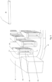
- FIG. 1 shows a heat exchanger 10 having a heat exchanger core 11, a first header 12 for conveying a first fluid into and out of the core 11, and a second header 14 for conveying a second fluid into and out of the core 11.
- the heat exchanger may be primarily used to exchange heat between the first fluid and the second fluid. However, heat may also be exchanged out through the sidewall 40 as well as out of the top and bottom sides of the heat exchanger core 11.
- the first header 12 connects to a first plurality of layers 30a,c,e,...30n of the heat exchanger core 11.
- the second header 14 connects to a second plurality of layers 30b,d,...30n-1 of the heat exchanger core 11.
- the first plurality of layers 30a,c,e...30n is interleaved with the second plurality of layers 30b,d...30n-1 such that for example, layer 30b is located between layers 30a and 30c.
- the first fluid flowing in the first plurality of layers 30a,c,e...30n is fluidly isolated from the second fluid flowing in the second plurality of layers 30b,d...30n-1.
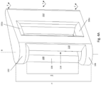
- These layers may be generically referred to by reference numeral 30 and any layer of the first and second pluralities of layers may be a layer 30 as shown in Figure 2 .
- the layer 30 comprises an inlet 32 and an outlet 34, and upper sheet 36, a lower sheet 38, and a sidewall 40.
- fluid is constrained by the upper sheet 36, lower sheet 38, and sidewall 40, so as to flow from the inlet 32, through the layer 30, to the outlet 34. That is, the upper sheet 36, lower sheet 38, and sidewall 40 together define a flowpath for fluid flowing in the layer 30.
- the upper sheet 36 has been moved away from the pins 100 and sidewall 40, in order to better show the features internal to the layer.
- the upper sheet 36 sits atop the pins 100 and sidewall.
- the upper sheet 36 of a given layer e.g. layer 30b
- Figure 3 shows a plurality of the pins 100 in perspective view.
- Each of the pins 100 is located in the fluid flowpath within the layer 30 and each pin 100 extends between the upper sheet 36 and lower sheet 38.
- the pin 100 comprises a top section 102, a middle section 104, and a bottom section 106.
- the top section 102 connects to the upper sheet 36 (which is removed in Figure 3 , to better shown the pins 100) and the bottom section 104 connects to the lower sheet 38.
- the middle section 104 connects between the top 102 and bottom sections 106.
- the pin 100 defines an axis B that extends from the top section 102, through the middle section 104, to the bottom section 106.
- the axis B extends normal to a first plane X, and the top section 102 extends generally within the first plane X.
- the axis B also extends normal to a second plane Y, and the middle section 104 extends generally within the second plane Y.
- the axis B also extends normal to a third plane Z, and the bottom section 106 extends generally within the third plane Z.
- the first plane X, second plane Y, and third plane Z are each parallel to one another and spaced apart from one another along the axis B.
- the top section 102 is monolithic. That is, it is a single unit, impermeable to fluid.
- the middle section comprises a plurality of sub-pins 108,110,112 that each respectively connect to the top section 102 and to the bottom section 106.
- the sub-pins 108,110,112 are spaced apart from one another such that fluid flowing in the second plane Y may flow between the sub-pins 108,110,112, i.e. may flow through the middle section 104.
- the top section 102 is monolithic such that fluid flowing in the first plane X must flow around the top section 102, either by flowing around the top section 102 generally within the plane X or by flowing down towards the second plane Y and then between the sub-pins 108,110,112.
- the bottom section 106 is monolithic such that fluid flowing in the third plane Z must flow around the bottom section 106, either by flowing around the bottom section 106 generally within the plane Z or by flowing up towards the second plane Y and then between the sub-pins 108,110,112.
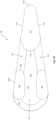
- Figure 4A shows a single pin 100 and Figure 4B shows a cross-section through the second plane Y, looking along axis B towards the bottom section 106.
- a first window 114 is defined at its top by the top section 102, and at its bottom by the bottom section 106, and at its sides by the first 108 and the second 110 of the sub-pins.
- a second window 116 is defined at its top by the top section 102, and at its bottom by the bottom section 106, and at its sides by the first 108 and third 112 of the sub-pins.
- a third window 118 is defined at its top by the top section 102, and at its bottom by the bottom section 106 and at its sides by the second 110 and third 112 of the sub-pins.
- fluid may flow through the windows 114,116,118, which is another way of saying that fluid may flow around and between the sub-pins 108,110,112.
- the use of sub-pins may increase the surface area of the middle section 104 compared to the top or bottom sections 102,106, which may increase the heat-transfer efficiency of the overall pin 100 as well as the pressure drop across the layer 30.
- the top and bottom sections 102,106 may provide a stronger connection to the upper and lower sheets 36,38, respectively, compared to connecting the sub-pins directly to the sheets 36,38.
- the top section 102 and bottom section 106 may each have a chamfered edge 102a,106a where they meet the middle section 104, to encourage laminar fluid flow.
- the sub-pins 108,110,112 may have an elongate cross-section (i.e. cross-section defined in the second plane Y).
- the cross-section may be defined by two straight sides 108a,c that are joined at their ends by two curved sides 108b,d.
- the second sub-pin 110 may have a cross-section defined by two straight sides that are joined at their ends by two curved sides.
- the first and second sub-pins may have identical cross-sectional shapes and sizes.
- the third sub-pin 112 may have a cross-section defined by two straight sides 112a,c that are joined at their ends by two curved sides 112b,d.
- the third sub-pin 112 may have the same cross-sectional shape and size as the first and/or second sub-pins 108,110 or it may have a different cross-sectional shape.
- any of the sub-pins may have any cross-sectional shape, as desired.
- one or more sub-pins may have a cross-section that is circular, elliptical, square, rectangular, triangular, hexagonal, or any other shape as desired.
- the cross-sectional shape of a given sub-pin may be chosen to assist with fluid flow in any desired manner. For example, some shapes may encourage turbulence in the fluid flow while other shapes may encourage laminar fluid flow around the sub-pins.
- Whether a given shape encourages laminar or turbulent flow additionally depends on the fluid used in the layer and the Reynolds number of the flow.
- the choice of shape will additionally depend on the choice of fluid (e.g. liquid vs gas; oil, water, air, CO2 etc.) as well as the expected flow rate through the core 11.
- the top section 102 may have a cross-section that is drop-shaped, as shown in Figure 4 .
- This is a shape having a generally triangular shape except that one side of the triangle curves outwards, while the end opposite this curved side tapers to a point or to a thin, rounded end.
- the bottom section 106 may have a cross-section that is drop-shaped, as shown in Figure 4 .
- This is a shape having a generally triangular shape except that one side of the triangle curves outwards, while the end opposite this curved side tapers to a point or to a thin, rounded end.
- top and bottom sections 102,106 may have identical cross-sectional shapes and sizes. Alternatively, they may have different shapes and sizes.
- either or both of the top and bottom sections can have any of: an airfoil shape, a rectangular shape, a triangular shape, a circular shape, a hexagonal shape, etc. as desired.
- Some cross-sectional shapes may encourage turbulence in the fluid flow while others may encourage laminar flow.
- the shapes of the top and bottom sections 102,106 may be selected as desired for a given application.
- the sub-pins may instead be spaced to define the corners of an equilateral triangle or a scalene triangle.
- the size and placement of the sub-pins will help define the size and orientation of the windows in the middle section.
- the size and orientation of the windows can be selected to modify the direction of a fluid flow past the pin.
- the cross-sectional shapes of the sub-pins may also assist in modifying the direction of fluid flow past the pin.
- the layer 30 shown in Figure 2 defines a generally U-shaped flowpath between the inlet 32 and outlet 34.
- a first portion of the first header 12 connects to the inlet side 30 of each layer 30a,c,e...n of the first plurality of layers, and, in use, fluid is pumped into the first portion and flows into the inlet side 32 of every layer connected to the first header 12.
- the fluid flows through each of the layers 30a,c,e...n and out through the outlet 34 of each layer of the first plurality of layers.
- the outlets 34 are all connected to a second portion of the first header 12, the second portion being fluidly isolated from the first portion. Fluid flows into the second portion and then out of the first header 12.
- a first portion of the second header 14 connects to the inlet side 30 of each layer 30b,d...n-1 and, in use, fluid is pumped into the first portion and flows into the inlet side 32 of every layer connected to the second header 14.
- the fluid flows through each of the layers 30a,c,e,...n and out through the outlet 34 of each layer.
- the outlets 34 are all connected to the second portion of the second header 14, the second portion being fluidly isolated from the first portion. Fluid flows into the second portion and then out of the second header 14.
- a first set of turning vanes 42a may turn the flow through 90 degrees, and a second set of turning vanes 42b may turn the flow through a further 90 degrees, to create the overall U-shaped flow path.
- a plurality of pins 100 may be disposed between the first and second sets of turning vanes 42a,b.
- the pins 100 shown in Figure 3 are all arranged within the layer 30 such that the window 114 of each pin 100 faces directly into a local flow direction. That is, for each pin 100, the flow direction of fluid immediately in front of the pin 100 is normal to the plane of the window 114. In this manner, fluid flows through the window 114 (which, as before, is defined between the top and bottom sections 102,106 and the first and second sub-pins 108,110) and towards the third sub-pin 112.
- fluid flowing into the middle section 116, through the window 114 may then be split when it impinges upon the third sub-pin 112 and the split portions of the fluid will then flow through the second 116 and third 118 windows, around the third sub-pin 112.
- the third sub-pin 112 may have a tapering shape, e.g. a drop-shape, to encourage laminar flow in the region beyond the third sub-pin.
- the fluid in layer 30 may flow in through the inlet 32 and along a first straight section past a plurality of pins 100, towards the first set 42a of turning vanes.
- the fluid may then be turned 90 degrees and flow past another plurality of pins 100 (each oriented such that its window 114 faces directly into the oncoming flow), towards the second set 42b of turning vanes.
- the fluid may then flow along another straight section past a further plurality of pins 100 (each oriented such that its window 114 faces directly into the oncoming flow) and out through the outlet 34.
- a turning vane may turn the fluid flow 180 degrees.
- a separation wall 44 may extend from a point between the inlet 32 and outlet 34, to a point near the sets of turning vanes 42a,42b, to further define the U-shaped flowpath.
- a height h of a pin 100 may be defined along the axis B, and the height h is the sum of the height of the top section 102, the height hm of the middle section 104, and the height of the bottom section 106.
- the height hm of the middle section may be, for example, greater than 50% of the overall pin height h, or may be greater than 75% of the pin height h, or greater than 90% of the pin height h.
- the height of the middle section hm is less than 100% of the height h of the pin (otherwise the top 102 and bottom sections 106 would not exist).
- the middle section 104 contains less material, viewed in cross-sectional plane Y, than either the top section 102 or the bottom section 106. This typically means that the middle section 104 introduces a weak point in the pin 100, i.e. a region in which pin breakage is more likely to occur.
- the height hm of the middle section 104 may be selected to balance the desired heat-transfer and pressure-drop characteristics against the need for strength of the overall pin 100. That is, for a stronger overall pin 100, the height hm of the middle section 104 may be kept smaller as a fraction of the overall height h.
- the cross-sectional sizes and/or material of the sub-pins 108,110,112 may be selected to determine a desired strength of the middle section 104.
- the top section 102 and bottom section 106 both provide strength to the overall pin 100 and provide a larger area, compared to the sub-pins, to connect the pin 100 to the upper sheet 36 and lower sheet 38.
- the pin 100 may be produced by additive manufacturing, such as by the process shown in Figure 5 .
- a lower sheet 38 is provided (step 502), optionally by additive manufacturing the lower sheet.
- the bottom section 106 of a pin 100 is additively manufactured to the lower sheet.
- the sub-pins (e.g. sub-pins 108,110,112) of the middle section 104 are additively manufactured on the bottom section 106, such that the sub-pins extend away from the lower sheet 38.
- the top section 102 of the pin 100 is additively manufactured on the sub-pins.
- an upper sheet is connected to the pin 100, optionally by additively manufacturing the upper sheet 36.
- the process may optionally include additively manufacturing one or more of: the sidewall 40, turning vanes 42a,b, further layers 30 on top of the initially formed layer 30, and one or more headers connecting to the or each layer 30.
- the pin 100 may be produced by a SLM powder-bed method of additive manufacturing.
- a first layer of metal powder is provided and a portion of the powder is melted by a laser beam to "print" the first layer of the overall object.
- the first layer is then lowered and a second layer of powder is brushed over the first layer, and a portion of the second layer of powder is melted by the laser beam to print a second layer of the overall object.
- a three-dimensional object is built-up layer-by-layer and, once all layers of the object have been printed, the loose (i.e. unmelted) powder is removed to reveal the object.
- the one or more pins 100 may be printed onto a pre-existing sheet of material that forms the lower sheet 38.
- the lower sheet 38 itself may be formed by additive manufacturing and, after the lower sheet 38 is formed, the pin(s) 100 may be formed on the lower sheet 38 by continuing the additive manufacturing process.
- the upper sheet 38 may be a pre-existing layer that is connected to the top sections 102 of the pins 100 after construction of the pins 100 on the lower sheet 38.
- the upper sheet 38 may be additively manufactured after the pins 100 have been manufactured, by continuing the additive manufacturing process.
- a new layer 30 (e.g. layer 30n-1) may be formed directly on top of the first layer 30.
- the upper sheet 36 of the first layer 30 becomes the bottom sheet 38 of the new layer 30. That is, the same layer of material may simultaneously function as the upper sheet 36 of one layer 30, and the bottom sheet 38 of another layer 30.
- the sidewall 40 may have an undulating cross-section, e.g. as shown in Figures 1 and 2 . This may increase the heat transfer across the sidewall 40 and/or may increase the strength of the sidewall for a given wall thickness.
- any or all parts of the heat exchanger 10 may be made from metal.
- some or all parts are made from an austenitic nickel-chromium-based superalloy, such as the Iconel family of metals manufactured by the Special Metals Corporation of New York state, USA.
- some or all parts may be made from an aluminium alloy or a copper alloy.
- the first and second fluids may be oil, such that the heat exchanger 10 is an oil-oil heat exchanger.
- the first fluid may be different from the second fluid.
- Other fluids, including air, water, or carbon dioxide are also envisaged for either or both of the first and second fluids.
- Heat exchanger 10 Heat exchanger core 11 First header 12 Second header 14 First plurality of layers 30a,c,e,...n Second plurality of layer 30b,d,...n-1 (generic) Layer 30 Inlet 32 Outlet 34 Upper sheet 36 Lower sheet 38 Sidewall 40 First set of turning vanes 42a Second set of turning vanes 42b Separation wall 44 Pin 100 Top section (of pin) 102 Chamfer of top section 102a Middle section (of pin) 104 Bottom section (of pin) 106 Chamfer of bottom section 106b First sub-pin 108 First sub-pin sides 108a-d Second sub-pin 110 Third sub-pin 112 Third sub-pin sides 112a-d Axis B Planes X,Y,Z Height of pin h Height of middle section hm First window 114 Second window 116 Third window 118
Landscapes
- Engineering & Computer Science (AREA)
- Physics & Mathematics (AREA)
- Thermal Sciences (AREA)
- Mechanical Engineering (AREA)
- General Engineering & Computer Science (AREA)
- Chemical & Material Sciences (AREA)
- Manufacturing & Machinery (AREA)
- Materials Engineering (AREA)
- Plasma & Fusion (AREA)
- Heat-Exchange Devices With Radiators And Conduit Assemblies (AREA)
Claims (15)
- Stift (100) für einen Wärmetauscher (10), wobei der Stift Folgendes umfasst:einen monolithischen oberen Abschnitt (102);einen monolithischen unteren Abschnitt (106); undeinen Mittelabschnitt (104), dadurch gekennzeichnet, dass der Mittelabschnitt eine Vielzahl von beabstandeten Unterstiften (108, 110, 112) umfasst, die sich zwischen dem oberen Abschnitt und dem unteren Abschnitt erstreckt, wobei die Vielzahl von Unterstiften ein oder mehrere Fenster (114, 116, 118) definiert, um einen Fluidstrom durch den Mittelabschnitt hindurch zu ermöglichen.
- Stift nach Anspruch 1, wobei der obere Abschnitt und/oder der untere Abschnitt eine Querschnittsform aufweisen, die eine der folgenden ist: tropfenförmig, tragflächenprofilförmig, rechteckig, kreisförmig oder polygonal.
- Stift nach Anspruch 1 oder 2, wobei einer oder mehrere der Unterstifte eine Querschnittsform aufweisen, die eine der folgenden ist: tropfenförmig, tragflächenprofilförmig, rechteckig, kreisförmig oder polygonal.
- Stift nach einem der vorhergehenden Ansprüche, wobei die Vielzahl von Unterstiften aus drei Unterstiften besteht, wobei die drei Unterstifte dazu angeordnet sind, die Eckpunkte eines gleichseitigen Dreiecks, eines ungleichschenkligen Dreiecks oder eines gleichschenkligen Dreiecks zu definieren.
- Stift nach einem der vorhergehenden Ansprüche, wobei der Stift eine Stifthöhe (h) aufweist und der Mittelabschnitt eine Mittelabschnittshöhe (hm) aufweist, wobei die Mittelabschnittshöhe (hm) kleiner als die Stifthöhe (h) und größer als 50 % der Stifthöhe (h) ist, wobei optional die Mittelabschnittshöhe (hm) größer als 75 % der Stifthöhe (h) ist.
- Stift nach einem der vorhergehenden Ansprüche, wobei der Stift aus einer Aluminiumlegierung, einer Kupferlegierung oder einer austenitischen Superlegierung auf Nickel-Chrom-Basis gebildet ist.
- Schicht (30) für einen Wärmetauscher (10), wobei die Schichteinen Einlass (32);einen Auslass (34);ein oberes Blech (36); undein unteres Blech (38) umfasst;wobei ein Fluidströmungspfad zwischen dem oberen und dem unteren Blech und von dem Einlass zu dem Auslass definiert ist;wobei mindestens ein Stift (100) in dem Strömungspfad angeordnet ist, wobei der oder jeder Stift ein Stift nach einem der vorhergehenden Ansprüche ist, wobei der obere Abschnitt des oder jedes Stifts mit dem oberen Blech verbunden ist und der untere Abschnitt des oder jedes Stifts mit dem unteren Blech verbunden ist.
- Schicht nach Anspruch 7, wobei der oder jeder Stift innerhalb der Schicht derart ausgerichtet ist, dass ein Fenster (114) des oder jedes Stifts direkt in eine lokale Strömungsrichtung weist, die von dem Einlass zu dem Auslass unmittelbar vor dem oder jedem Stift definiert ist.
- Schicht nach Anspruch 8, wobei der oder jeder Stift drei Unterstifte umfasst, wobei ein erster (108) und ein zweiter (110) der Unterstifte das Fenster (114) definieren, das direkt in die lokale Strömungsrichtung weist, und wobei sich ein dritter (112) der Unterstifte derart in der Strömungsrichtung direkt hinter dem Fenster (114) befindet, dass sich in Verwendung ein Teil des Fluids, das durch das Fenster (114) hindurch strömt, in zwei Teile teilt, um um beide Seiten des dritten Unterstifts (112) herum zu fließen.
- Schicht nach Anspruch 7, 8 oder 9, wobei der Strömungspfad U-förmig ist;
wobei sich der Strömungspfad entlang eines ersten geraden Abschnitts von dem Einlass zu einer oder mehreren Taumelschaufeln (42a, b) erstreckt und sich der Strömungspfad entlang eines zweiten geraden Abschnitts von der einen oder den mehreren Taumelschaufeln zu dem Auslass erstreckt, wobei der Auslass an den Einlass angrenzt und von diesem durch eine Trennwand (44) getrennt ist. - Wärmetauscher (10), der eine erste Schicht (30a) und eine zweite Schicht (30b) umfasst,wobei die erste Schicht eine Schicht nach einem der Ansprüche 7 bis 10 ist;wobei die zweite Schicht eine Schicht nach einem der Ansprüche 7 bis 10 ist; undwobei das obere Blech der zweiten Schicht auch das untere Blech der ersten Schicht ist.
- Additives Fertigungsverfahren zum Herstellen einer Schicht (30) für einen Wärmetauscher (10), wobei das Verfahren Folgendes umfasst:
additives Fertigen eines oder mehrerer Stifte (100) auf einem unteren Blech (38), wobei das additive Fertigen des oder jedes Stifts Folgendes umfasst:additives Fertigen eines monolithischen unteren Abschnitts (106) eines Stifts (100) auf einem unteren Blech (38),additives Fertigen einer Vielzahl von Unterstiften (108, 110, 112) auf dem unteren Abschnitt, wobei sich die Unterstifte von dem unteren Blech (38) weg erstrecken,additives Fertigen eines monolithischen oberen Abschnitts (102), der mit jedem der Unterstifte verbunden ist; und wobei das Verfahren fernerVerbinden eines oberen Blechs (36) mit dem oberen Abschnitt des oder jedes Stifts umfasst. - Verfahren nach Anspruch 12, umfassend additives Fertigen einer Seitenwand (40), die sich zwischen dem unteren Blech und dem oberen Blech erstreckt; und optional additives Fertigen eines oder mehrerer Sätze von Taumelschaufeln (42a, b) auf dem unteren Blech zur gleichen Zeit wie additives Fertigen des oder jedes Stifts (100).
- Verfahren zum additiven Fertigen eines Wärmetauschers (10), wobei das Verfahren Folgendes umfasst:additives Fertigen einer ersten Vielzahl von Schichten, die mit einer zweiten Vielzahl von Schichten verschachtelt ist, wobei jede Schicht der ersten und der zweiten Vielzahl von Schichten über das Verfahren nach Anspruch 12 oder 13 gefertigt wird;additives Fertigen eines ersten Kopfstücks (12), das mit jeder der ersten Vielzahl von Schichten in Fluidverbindung steht; und additives Fertigen eines zweiten Kopfstücks (14), das mit jeder der zweiten Vielzahl von Schichten in Fluidverbindung steht.
- Verfahren nach einem der Ansprüche 12 bis 14, wobei jeder Schritt des additiven Fertigens unter Verwendung eines Metallpulverbett-SLM-Prozesses zur additiven Fertigung durchgeführt wird, wobei optional ein Pulver des Metallpulverbetts eines von einer Aluminiumlegierung, einer Kupferlegierung und einer austenitischen Superlegierung auf Nickel-Chrom-Basis ist.
Priority Applications (2)
| Application Number | Priority Date | Filing Date | Title |
|---|---|---|---|
| EP21461527.0A EP4063779B1 (de) | 2021-03-26 | 2021-03-26 | Wärmetauscherstifte |
| US17/704,054 US20220307776A1 (en) | 2021-03-26 | 2022-03-25 | Heat-exchanger pins |
Applications Claiming Priority (1)
| Application Number | Priority Date | Filing Date | Title |
|---|---|---|---|
| EP21461527.0A EP4063779B1 (de) | 2021-03-26 | 2021-03-26 | Wärmetauscherstifte |
Publications (2)
| Publication Number | Publication Date |
|---|---|
| EP4063779A1 EP4063779A1 (de) | 2022-09-28 |
| EP4063779B1 true EP4063779B1 (de) | 2024-01-10 |
Family
ID=75277955
Family Applications (1)
| Application Number | Title | Priority Date | Filing Date |
|---|---|---|---|
| EP21461527.0A Active EP4063779B1 (de) | 2021-03-26 | 2021-03-26 | Wärmetauscherstifte |
Country Status (2)
| Country | Link |
|---|---|
| US (1) | US20220307776A1 (de) |
| EP (1) | EP4063779B1 (de) |
Family Cites Families (14)
| Publication number | Priority date | Publication date | Assignee | Title |
|---|---|---|---|---|
| US2595457A (en) * | 1947-06-03 | 1952-05-06 | Air Preheater | Pin fin heat exchanger |
| JP3122173B2 (ja) * | 1990-11-09 | 2001-01-09 | 株式会社東芝 | 放熱器、放熱装置および放熱器の製造方法 |
| US5419041A (en) * | 1992-08-04 | 1995-05-30 | Aqty Co., Ltd. | Process for manufacturing a pin type radiating fin |
| US5447189A (en) * | 1993-12-16 | 1995-09-05 | Mcintyre; Gerald L. | Method of making heat sink having elliptical pins |
| US5854739A (en) * | 1996-02-20 | 1998-12-29 | International Electronic Research Corp. | Long fin omni-directional heat sink |
| US6318455B1 (en) * | 1999-07-14 | 2001-11-20 | Mitsubishi Heavy Industries, Ltd. | Heat exchanger |
| US6273186B1 (en) * | 2000-03-13 | 2001-08-14 | Satcon Technology Corporation | Low-cost, high density, staggered pin fin array |
| US6817405B2 (en) * | 2002-06-03 | 2004-11-16 | International Business Machines Corporation | Apparatus having forced fluid cooling and pin-fin heat sink |
| US7182124B2 (en) * | 2004-08-31 | 2007-02-27 | Egbon Electronics Ltd. | Heat sink structure |
| US7301770B2 (en) * | 2004-12-10 | 2007-11-27 | International Business Machines Corporation | Cooling apparatus, cooled electronic module, and methods of fabrication thereof employing thermally conductive, wire-bonded pin fins |
| US10048019B2 (en) * | 2014-12-22 | 2018-08-14 | Hamilton Sundstrand Corporation | Pins for heat exchangers |
| EP3257355A4 (de) | 2015-02-13 | 2018-08-29 | National University Corporation Nagoya University | Setzlingaufzuchtelement und setzlingaufzuchtset zum pfropfen und verfahren zur herstellung eines gepfropften setzlings |
| US20170356696A1 (en) * | 2016-06-13 | 2017-12-14 | Hamilton Sundstrand Corporation | Complex pin fin heat exchanger |
| CN109990640B (zh) * | 2019-03-12 | 2020-06-26 | 西安交通大学 | 一种开槽式流线肋型结构的换热板 |
-
2021
- 2021-03-26 EP EP21461527.0A patent/EP4063779B1/de active Active
-
2022
- 2022-03-25 US US17/704,054 patent/US20220307776A1/en active Pending
Also Published As
| Publication number | Publication date |
|---|---|
| US20220307776A1 (en) | 2022-09-29 |
| EP4063779A1 (de) | 2022-09-28 |
Similar Documents
| Publication | Publication Date | Title |
|---|---|---|
| US10926364B2 (en) | Plate-fin heat exchanger core design for improved manufacturing | |
| JP6163190B2 (ja) | 熱交換器 | |
| US10801790B2 (en) | Plate fin heat exchanger flexible manifold structure | |
| US8453719B2 (en) | Heat transfer surfaces with flanged apertures | |
| US11226158B2 (en) | Heat exchanger fractal splitter | |
| TWI463104B (zh) | 熱交換器穿洞鰭 | |
| JP5872859B2 (ja) | 熱交換器 | |
| AU660453B2 (en) | Heat exchanger | |
| JP2022008275A (ja) | 熱交換器 | |
| CN112857103A (zh) | 一种紧凑式换热器及其非对称翼型换热板片 | |
| EP4063779B1 (de) | Wärmetauscherstifte | |
| US20110180247A1 (en) | Heat exchanger | |
| EP4209348A1 (de) | Wärmetauscher mit gewellten trennblechen | |
| US20230400258A1 (en) | Heat exchanger core layer | |
| EP4279856A1 (de) | Kernschicht für wärmetauscher | |
| US20230366640A1 (en) | Heat exchanger core layer | |
| CN113154916A (zh) | 一种顺流一次表面式换热器芯体及换热器 | |
| CN105215228A (zh) | 具有带凸缘的孔口的传热面 | |
| CN215930646U (zh) | 一种顺流一次表面式换热器芯体及换热器 | |
| CN219693947U (zh) | 一种高效紧凑式扩散焊接换热器芯体 | |
| EP3653984A2 (de) | Flexible verteilerstruktur für plattenrippenwärmetauscher |
Legal Events
| Date | Code | Title | Description |
|---|---|---|---|
| PUAI | Public reference made under article 153(3) epc to a published international application that has entered the european phase |
Free format text: ORIGINAL CODE: 0009012 |
|
| STAA | Information on the status of an ep patent application or granted ep patent |
Free format text: STATUS: THE APPLICATION HAS BEEN PUBLISHED |
|
| AK | Designated contracting states |
Kind code of ref document: A1 Designated state(s): AL AT BE BG CH CY CZ DE DK EE ES FI FR GB GR HR HU IE IS IT LI LT LU LV MC MK MT NL NO PL PT RO RS SE SI SK SM TR |
|
| STAA | Information on the status of an ep patent application or granted ep patent |
Free format text: STATUS: REQUEST FOR EXAMINATION WAS MADE |
|
| 17P | Request for examination filed |
Effective date: 20230313 |
|
| RBV | Designated contracting states (corrected) |
Designated state(s): AL AT BE BG CH CY CZ DE DK EE ES FI FR GB GR HR HU IE IS IT LI LT LU LV MC MK MT NL NO PL PT RO RS SE SI SK SM TR |
|
| GRAP | Despatch of communication of intention to grant a patent |
Free format text: ORIGINAL CODE: EPIDOSNIGR1 |
|
| STAA | Information on the status of an ep patent application or granted ep patent |
Free format text: STATUS: GRANT OF PATENT IS INTENDED |
|
| RIC1 | Information provided on ipc code assigned before grant |
Ipc: F28F 3/02 20060101AFI20230704BHEP |
|
| INTG | Intention to grant announced |
Effective date: 20230803 |
|
| RIN1 | Information on inventor provided before grant (corrected) |
Inventor name: MECZKOWSKI, TOMASZ Inventor name: SIUDZINSKI, HUBERT Inventor name: RUBALEWSKI, JAROSLAW |
|
| GRAS | Grant fee paid |
Free format text: ORIGINAL CODE: EPIDOSNIGR3 |
|
| GRAA | (expected) grant |
Free format text: ORIGINAL CODE: 0009210 |
|
| STAA | Information on the status of an ep patent application or granted ep patent |
Free format text: STATUS: THE PATENT HAS BEEN GRANTED |
|
| AK | Designated contracting states |
Kind code of ref document: B1 Designated state(s): AL AT BE BG CH CY CZ DE DK EE ES FI FR GB GR HR HU IE IS IT LI LT LU LV MC MK MT NL NO PL PT RO RS SE SI SK SM TR |
|
| REG | Reference to a national code |
Ref country code: GB Ref legal event code: FG4D |
|
| REG | Reference to a national code |
Ref country code: CH Ref legal event code: EP |
|
| REG | Reference to a national code |
Ref country code: DE Ref legal event code: R096 Ref document number: 602021008522 Country of ref document: DE |
|
| REG | Reference to a national code |
Ref country code: IE Ref legal event code: FG4D |
|
| PGFP | Annual fee paid to national office [announced via postgrant information from national office to epo] |
Ref country code: DE Payment date: 20240220 Year of fee payment: 4 |
|
| REG | Reference to a national code |
Ref country code: LT Ref legal event code: MG9D |
|
| REG | Reference to a national code |
Ref country code: NL Ref legal event code: MP Effective date: 20240110 |
|
| PGFP | Annual fee paid to national office [announced via postgrant information from national office to epo] |
Ref country code: FR Payment date: 20240220 Year of fee payment: 4 |
|
| REG | Reference to a national code |
Ref country code: AT Ref legal event code: MK05 Ref document number: 1649211 Country of ref document: AT Kind code of ref document: T Effective date: 20240110 |
|
| PG25 | Lapsed in a contracting state [announced via postgrant information from national office to epo] |
Ref country code: NL Free format text: LAPSE BECAUSE OF FAILURE TO SUBMIT A TRANSLATION OF THE DESCRIPTION OR TO PAY THE FEE WITHIN THE PRESCRIBED TIME-LIMIT Effective date: 20240110 |
|
| PG25 | Lapsed in a contracting state [announced via postgrant information from national office to epo] |
Ref country code: NL Free format text: LAPSE BECAUSE OF FAILURE TO SUBMIT A TRANSLATION OF THE DESCRIPTION OR TO PAY THE FEE WITHIN THE PRESCRIBED TIME-LIMIT Effective date: 20240110 |
|
| PG25 | Lapsed in a contracting state [announced via postgrant information from national office to epo] |
Ref country code: IS Free format text: LAPSE BECAUSE OF FAILURE TO SUBMIT A TRANSLATION OF THE DESCRIPTION OR TO PAY THE FEE WITHIN THE PRESCRIBED TIME-LIMIT Effective date: 20240510 |
|
| PG25 | Lapsed in a contracting state [announced via postgrant information from national office to epo] |
Ref country code: LT Free format text: LAPSE BECAUSE OF FAILURE TO SUBMIT A TRANSLATION OF THE DESCRIPTION OR TO PAY THE FEE WITHIN THE PRESCRIBED TIME-LIMIT Effective date: 20240110 |
|
| PG25 | Lapsed in a contracting state [announced via postgrant information from national office to epo] |
Ref country code: GR Free format text: LAPSE BECAUSE OF FAILURE TO SUBMIT A TRANSLATION OF THE DESCRIPTION OR TO PAY THE FEE WITHIN THE PRESCRIBED TIME-LIMIT Effective date: 20240411 |
|
| PG25 | Lapsed in a contracting state [announced via postgrant information from national office to epo] |
Ref country code: RS Free format text: LAPSE BECAUSE OF FAILURE TO SUBMIT A TRANSLATION OF THE DESCRIPTION OR TO PAY THE FEE WITHIN THE PRESCRIBED TIME-LIMIT Effective date: 20240410 Ref country code: HR Free format text: LAPSE BECAUSE OF FAILURE TO SUBMIT A TRANSLATION OF THE DESCRIPTION OR TO PAY THE FEE WITHIN THE PRESCRIBED TIME-LIMIT Effective date: 20240110 |
|
| PG25 | Lapsed in a contracting state [announced via postgrant information from national office to epo] |
Ref country code: ES Free format text: LAPSE BECAUSE OF FAILURE TO SUBMIT A TRANSLATION OF THE DESCRIPTION OR TO PAY THE FEE WITHIN THE PRESCRIBED TIME-LIMIT Effective date: 20240110 |
|
| PG25 | Lapsed in a contracting state [announced via postgrant information from national office to epo] |
Ref country code: AT Free format text: LAPSE BECAUSE OF FAILURE TO SUBMIT A TRANSLATION OF THE DESCRIPTION OR TO PAY THE FEE WITHIN THE PRESCRIBED TIME-LIMIT Effective date: 20240110 |
|
| PG25 | Lapsed in a contracting state [announced via postgrant information from national office to epo] |
Ref country code: RS Free format text: LAPSE BECAUSE OF FAILURE TO SUBMIT A TRANSLATION OF THE DESCRIPTION OR TO PAY THE FEE WITHIN THE PRESCRIBED TIME-LIMIT Effective date: 20240410 Ref country code: NO Free format text: LAPSE BECAUSE OF FAILURE TO SUBMIT A TRANSLATION OF THE DESCRIPTION OR TO PAY THE FEE WITHIN THE PRESCRIBED TIME-LIMIT Effective date: 20240410 Ref country code: LT Free format text: LAPSE BECAUSE OF FAILURE TO SUBMIT A TRANSLATION OF THE DESCRIPTION OR TO PAY THE FEE WITHIN THE PRESCRIBED TIME-LIMIT Effective date: 20240110 Ref country code: IS Free format text: LAPSE BECAUSE OF FAILURE TO SUBMIT A TRANSLATION OF THE DESCRIPTION OR TO PAY THE FEE WITHIN THE PRESCRIBED TIME-LIMIT Effective date: 20240510 Ref country code: HR Free format text: LAPSE BECAUSE OF FAILURE TO SUBMIT A TRANSLATION OF THE DESCRIPTION OR TO PAY THE FEE WITHIN THE PRESCRIBED TIME-LIMIT Effective date: 20240110 Ref country code: GR Free format text: LAPSE BECAUSE OF FAILURE TO SUBMIT A TRANSLATION OF THE DESCRIPTION OR TO PAY THE FEE WITHIN THE PRESCRIBED TIME-LIMIT Effective date: 20240411 Ref country code: ES Free format text: LAPSE BECAUSE OF FAILURE TO SUBMIT A TRANSLATION OF THE DESCRIPTION OR TO PAY THE FEE WITHIN THE PRESCRIBED TIME-LIMIT Effective date: 20240110 Ref country code: BG Free format text: LAPSE BECAUSE OF FAILURE TO SUBMIT A TRANSLATION OF THE DESCRIPTION OR TO PAY THE FEE WITHIN THE PRESCRIBED TIME-LIMIT Effective date: 20240110 Ref country code: AT Free format text: LAPSE BECAUSE OF FAILURE TO SUBMIT A TRANSLATION OF THE DESCRIPTION OR TO PAY THE FEE WITHIN THE PRESCRIBED TIME-LIMIT Effective date: 20240110 |
|
| PG25 | Lapsed in a contracting state [announced via postgrant information from national office to epo] |
Ref country code: PL Free format text: LAPSE BECAUSE OF FAILURE TO SUBMIT A TRANSLATION OF THE DESCRIPTION OR TO PAY THE FEE WITHIN THE PRESCRIBED TIME-LIMIT Effective date: 20240110 Ref country code: PT Free format text: LAPSE BECAUSE OF FAILURE TO SUBMIT A TRANSLATION OF THE DESCRIPTION OR TO PAY THE FEE WITHIN THE PRESCRIBED TIME-LIMIT Effective date: 20240510 |
|
| PG25 | Lapsed in a contracting state [announced via postgrant information from national office to epo] |
Ref country code: SE Free format text: LAPSE BECAUSE OF FAILURE TO SUBMIT A TRANSLATION OF THE DESCRIPTION OR TO PAY THE FEE WITHIN THE PRESCRIBED TIME-LIMIT Effective date: 20240110 Ref country code: PT Free format text: LAPSE BECAUSE OF FAILURE TO SUBMIT A TRANSLATION OF THE DESCRIPTION OR TO PAY THE FEE WITHIN THE PRESCRIBED TIME-LIMIT Effective date: 20240510 Ref country code: PL Free format text: LAPSE BECAUSE OF FAILURE TO SUBMIT A TRANSLATION OF THE DESCRIPTION OR TO PAY THE FEE WITHIN THE PRESCRIBED TIME-LIMIT Effective date: 20240110 Ref country code: LV Free format text: LAPSE BECAUSE OF FAILURE TO SUBMIT A TRANSLATION OF THE DESCRIPTION OR TO PAY THE FEE WITHIN THE PRESCRIBED TIME-LIMIT Effective date: 20240110 |