EP4063642A1 - Stop position controller for engine, engine system, vehicle, and method of stopping engine - Google Patents
Stop position controller for engine, engine system, vehicle, and method of stopping engine Download PDFInfo
- Publication number
- EP4063642A1 EP4063642A1 EP21216195.4A EP21216195A EP4063642A1 EP 4063642 A1 EP4063642 A1 EP 4063642A1 EP 21216195 A EP21216195 A EP 21216195A EP 4063642 A1 EP4063642 A1 EP 4063642A1
- Authority
- EP
- European Patent Office
- Prior art keywords
- stop
- engine
- intake
- intake valve
- close timing
- Prior art date
- Legal status (The legal status is an assumption and is not a legal conclusion. Google has not performed a legal analysis and makes no representation as to the accuracy of the status listed.)
- Pending
Links
Images


Classifications
-
- F—MECHANICAL ENGINEERING; LIGHTING; HEATING; WEAPONS; BLASTING
- F02—COMBUSTION ENGINES; HOT-GAS OR COMBUSTION-PRODUCT ENGINE PLANTS
- F02N—STARTING OF COMBUSTION ENGINES; STARTING AIDS FOR SUCH ENGINES, NOT OTHERWISE PROVIDED FOR
- F02N19/00—Starting aids for combustion engines, not otherwise provided for
- F02N19/005—Aiding engine start by starting from a predetermined position, e.g. pre-positioning or reverse rotation
-
- F—MECHANICAL ENGINEERING; LIGHTING; HEATING; WEAPONS; BLASTING
- F02—COMBUSTION ENGINES; HOT-GAS OR COMBUSTION-PRODUCT ENGINE PLANTS
- F02D—CONTROLLING COMBUSTION ENGINES
- F02D13/00—Controlling the engine output power by varying inlet or exhaust valve operating characteristics, e.g. timing
- F02D13/02—Controlling the engine output power by varying inlet or exhaust valve operating characteristics, e.g. timing during engine operation
- F02D13/0223—Variable control of the intake valves only
- F02D13/0234—Variable control of the intake valves only changing the valve timing only
- F02D13/0238—Variable control of the intake valves only changing the valve timing only by shifting the phase, i.e. the opening periods of the valves are constant
-
- F—MECHANICAL ENGINEERING; LIGHTING; HEATING; WEAPONS; BLASTING
- F02—COMBUSTION ENGINES; HOT-GAS OR COMBUSTION-PRODUCT ENGINE PLANTS
- F02D—CONTROLLING COMBUSTION ENGINES
- F02D13/00—Controlling the engine output power by varying inlet or exhaust valve operating characteristics, e.g. timing
- F02D13/08—Controlling the engine output power by varying inlet or exhaust valve operating characteristics, e.g. timing for rendering engine inoperative or idling
-
- F—MECHANICAL ENGINEERING; LIGHTING; HEATING; WEAPONS; BLASTING
- F02—COMBUSTION ENGINES; HOT-GAS OR COMBUSTION-PRODUCT ENGINE PLANTS
- F02D—CONTROLLING COMBUSTION ENGINES
- F02D41/00—Electrical control of supply of combustible mixture or its constituents
- F02D41/02—Circuit arrangements for generating control signals
- F02D41/04—Introducing corrections for particular operating conditions
- F02D41/042—Introducing corrections for particular operating conditions for stopping the engine
-
- F—MECHANICAL ENGINEERING; LIGHTING; HEATING; WEAPONS; BLASTING
- F02—COMBUSTION ENGINES; HOT-GAS OR COMBUSTION-PRODUCT ENGINE PLANTS
- F02D—CONTROLLING COMBUSTION ENGINES
- F02D13/00—Controlling the engine output power by varying inlet or exhaust valve operating characteristics, e.g. timing
- F02D13/02—Controlling the engine output power by varying inlet or exhaust valve operating characteristics, e.g. timing during engine operation
- F02D13/0203—Variable control of intake and exhaust valves
- F02D13/0215—Variable control of intake and exhaust valves changing the valve timing only
- F02D13/0219—Variable control of intake and exhaust valves changing the valve timing only by shifting the phase, i.e. the opening periods of the valves are constant
-
- F—MECHANICAL ENGINEERING; LIGHTING; HEATING; WEAPONS; BLASTING
- F02—COMBUSTION ENGINES; HOT-GAS OR COMBUSTION-PRODUCT ENGINE PLANTS
- F02D—CONTROLLING COMBUSTION ENGINES
- F02D13/00—Controlling the engine output power by varying inlet or exhaust valve operating characteristics, e.g. timing
- F02D13/02—Controlling the engine output power by varying inlet or exhaust valve operating characteristics, e.g. timing during engine operation
- F02D13/0261—Controlling the valve overlap
-
- F—MECHANICAL ENGINEERING; LIGHTING; HEATING; WEAPONS; BLASTING
- F02—COMBUSTION ENGINES; HOT-GAS OR COMBUSTION-PRODUCT ENGINE PLANTS
- F02D—CONTROLLING COMBUSTION ENGINES
- F02D41/00—Electrical control of supply of combustible mixture or its constituents
- F02D41/0002—Controlling intake air
- F02D2041/001—Controlling intake air for engines with variable valve actuation
-
- F—MECHANICAL ENGINEERING; LIGHTING; HEATING; WEAPONS; BLASTING
- F02—COMBUSTION ENGINES; HOT-GAS OR COMBUSTION-PRODUCT ENGINE PLANTS
- F02D—CONTROLLING COMBUSTION ENGINES
- F02D41/00—Electrical control of supply of combustible mixture or its constituents
- F02D41/0002—Controlling intake air
-
- F—MECHANICAL ENGINEERING; LIGHTING; HEATING; WEAPONS; BLASTING
- F02—COMBUSTION ENGINES; HOT-GAS OR COMBUSTION-PRODUCT ENGINE PLANTS
- F02N—STARTING OF COMBUSTION ENGINES; STARTING AIDS FOR SUCH ENGINES, NOT OTHERWISE PROVIDED FOR
- F02N11/00—Starting of engines by means of electric motors
- F02N11/08—Circuits or control means specially adapted for starting of engines
- F02N11/0814—Circuits or control means specially adapted for starting of engines comprising means for controlling automatic idle-start-stop
-
- F—MECHANICAL ENGINEERING; LIGHTING; HEATING; WEAPONS; BLASTING
- F02—COMBUSTION ENGINES; HOT-GAS OR COMBUSTION-PRODUCT ENGINE PLANTS
- F02N—STARTING OF COMBUSTION ENGINES; STARTING AIDS FOR SUCH ENGINES, NOT OTHERWISE PROVIDED FOR
- F02N11/00—Starting of engines by means of electric motors
- F02N11/08—Circuits or control means specially adapted for starting of engines
- F02N11/0848—Circuits or control means specially adapted for starting of engines with means for detecting successful engine start, e.g. to stop starter actuation
-
- F—MECHANICAL ENGINEERING; LIGHTING; HEATING; WEAPONS; BLASTING
- F02—COMBUSTION ENGINES; HOT-GAS OR COMBUSTION-PRODUCT ENGINE PLANTS
- F02N—STARTING OF COMBUSTION ENGINES; STARTING AIDS FOR SUCH ENGINES, NOT OTHERWISE PROVIDED FOR
- F02N19/00—Starting aids for combustion engines, not otherwise provided for
- F02N19/005—Aiding engine start by starting from a predetermined position, e.g. pre-positioning or reverse rotation
- F02N2019/008—Aiding engine start by starting from a predetermined position, e.g. pre-positioning or reverse rotation the engine being stopped in a particular position
-
- F—MECHANICAL ENGINEERING; LIGHTING; HEATING; WEAPONS; BLASTING
- F02—COMBUSTION ENGINES; HOT-GAS OR COMBUSTION-PRODUCT ENGINE PLANTS
- F02N—STARTING OF COMBUSTION ENGINES; STARTING AIDS FOR SUCH ENGINES, NOT OTHERWISE PROVIDED FOR
- F02N2300/00—Control related aspects of engine starting
- F02N2300/20—Control related aspects of engine starting characterised by the control method
- F02N2300/2011—Control involving a delay; Control involving a waiting period before engine stop or engine start
Definitions
- the present invention relates to a stop position controller, particularly a stop position controller that is provided for an engine capable of being forcibly started by causing a crankshaft to rotate.
- control is executed immediately before the stop of the engine. That is, control is executed to increase an opening degree of a throttle valve after completion of air intake of a stop-time expansion stroke cylinder (a final expansion cylinder in Patent document 1) as a cylinder that is stopped in an expansion stroke, so as to increase an intake amount of a stop-time compression stroke cylinder (a final compression cylinder in Patent document 1) as a cylinder that is stopped in a compression stroke.
- the intake amount in the stop-time compression stroke cylinder tends to be larger than the intake amount in the stop-time expansion stroke cylinder whose intake stroke is terminated earlier than the stop-time compression stroke cylinder.
- the opening degree of the throttle valve is simply increased immediately before the engine stop to increase the intake amount of the stop-time compression stroke cylinder, the intake amount of the stop-time compression stroke cylinder becomes excessive, which possibly shifts a position of the stop-time compression stroke cylinder to bottom dead center side from an appropriate position.
- the intake amount of the stop-time compression stroke cylinder becomes excessively larger than the intake amount of the stop-time expansion stroke cylinder. Accordingly, a force by the intake air of the stop-time expansion stroke cylinder to push down a piston in the cylinder (in other words, a force of lifting the piston in the stop-time compression stroke cylinder) is insufficient for a force by the intake air of the stop-time compression stroke cylinder to push down the piston in the cylinder, which possibly shifts the position of the stop-time compression stroke cylinder to the bottom dead center side from the appropriate position. Thus, with the device disclosed in Patent document 1, it may be impossible to reduce the torque of the start means that is required to start the engine.
- the present invention has been made in view of circumstances as described above and therefore has a purpose of reliably reducing torque of start means that is consumed for an engine start by controlling a position of each cylinder at an engine stop to a position suited for the start.
- the present invention is particularly a stop position controller provided for an engine including: plural cylinders; plural intake ports, each of which communicates with respective one of the cylinders; plural intake valves, each of which opens/closes respective one of the intake ports; fuel supply means that supplies fuel to each of the cylinders; a piston that is provided in each of the cylinders in a reciprocal manner; a crankshaft that rotates in an interlocking manner with reciprocating motion of the piston; and start means capable of forcibly starting the engine by causing the crankshaft to rotate.
- the stop position controller for an engine includes: intake valve close timing change means that collectively changes intake valve close timing as close timing of the plural intake valves; and control means that controls each section in the engine including the fuel supply means and the intake valve close timing change means.
- the control means performs fuel cut to stop a fuel supply into the cylinder by the fuel supply means and, after the fuel cut, controls the intake valve close timing change means such that a retarded amount of the intake valve close timing before or immediately before a stop of a stop-time compression stroke cylinder, which is the cylinder stopped in a compression stroke, from intake bottom dead center is larger than a retarded amount of the intake valve close timing before or immediately before a stop of a stop-time expansion stroke cylinder, which is the cylinder stopped in an expansion stroke, from the intake bottom dead center.
- the retarded amount of the intake valve close timing immediately before the stop of the stop-time compression stroke cylinder from the intake bottom dead center is set to be larger than the retarded amount of the intake valve close timing immediately before the stop of the stop-time expansion stroke cylinder from the intake bottom dead center.
- the present invention it is possible to suppress an increase in the intake amount of the stop-time compression stroke cylinder, which is likely to be increased in association with a pressure increase in an intake passage immediately before an engine stop, and it is thus possible to prevent the intake amount of the stop-time compression stroke cylinder from becoming excessively larger than the intake amount of the stop-time expansion stroke cylinder. Therefore, it is possible to prevent a position of the stop-time compression stroke cylinder from being shifted to the bottom dead center side from an appropriate position.
- the control means retards the intake valve close timing to specified pre-valve close timing by the intake valve close timing change means, and after the intake valve close timing reaches the pre-valve close timing and specified timing arrives, retards the intake valve close timing from the pre-valve close timing by the intake valve close timing change means.
- the engine includes a throttle valve that opens/closes an intake passage communicating with the plural intake ports, and the control means predicts a stop position of the stop-time compression stroke cylinder after the fuel cut and increases an opening degree of the throttle valve when predicting that the stop position of the stop-time compression stroke cylinder is on a top dead center side from a specified target range.
- the present invention can increase a possibility of setting the stop position of each of the cylinders at the position suited for the start.
- the opening degree of the throttle valve is increased in the case where it is predicted that the stop position of the stop-time compression stroke cylinder is located on the top dead center side from the target range.
- the stop position of the stop-time compression stroke cylinder is set to be equal to or larger than 40 degrees before compression top dead center and equal to or smaller than 75 degrees before the compression top dead center in crank angle in a six-cylinder engine having six cylinders, the engine can be started while torque of the start means is suppressed to be equal to or lower than a specified value.
- the target range is particularly set to a range of 40 degrees or larger before compression top dead center and 75 degrees or smaller before the compression top dead center in crank angle. Further particularly, the target range is a range from 40 to 75 degrees before the compression top dead center in crank angle.
- the stop position controller as described above, it is possible to reliably reduce the torque of the start means consumed for the engine start by controlling the position of each of the cylinders at the engine stop to the position suited for the start.
- Fig. 1 is a schematic configuration diagram of a vehicle 100 on which an engine E, to which a stop position controller for an engine according to an embodiment of the present invention is applied, is mounted.
- the vehicle 100 may be a hybrid vehicle that includes the engine E and a motor M as drive sources of the vehicle 100 (a wheel 101).
- the motor M corresponds to the "start means" in the claims.
- the vehicle 100 particularly includes, in addition to the wheel 101, the engine E, and the motor M; a clutch 102 that couples an output shaft of the engine E and a rotary shaft of the motor M in an engageable/disengageable manner; a battery 103 that exchanges electric power with the motor M; a transmission 104 that is coupled to the motor M; and a power transmission device 105 that includes a driveshaft 106 coupled to the wheel 101, a differential gear, and the like and couples the transmission 104 and the driveshaft 106.
- Fig. 2 is a schematic configuration view of the engine E.
- the engine E particularly includes: an engine body 1; an intake passage 30 through which intake air to be introduced into the engine body 1 flows; an exhaust passage 40 through which exhaust gas discharged from the engine body 1 flows; and an EGR device 44 that circulates EGR gas as some of the exhaust gas flowing through the exhaust passage 40 into the intake passage 30.
- the engine E may also include a turbocharger 46 having: a turbine 48 that is provided in the exhaust passage 40; and a compressor 47 that is rotationally driven by the turbine 48 provided in the intake passage 30.
- the engine E in this embodiment is a four-stroke diesel engine and is driven when being supplied with fuel that has diesel fuel as a main component.
- the engine body 1 particularly has: a cylinder block 3 that is formed with a cylinder 2; and a cylinder head 4 that covers the cylinder block 3.
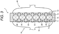
- Fig. 3 is a schematic cross-sectional view of the engine body 1.
- the engine E in this embodiment is particularly an in-line six-cylinder engine.
- the engine body 1 (in detail, the cylinder block 3) is formed with the six cylinders 2 (a first cylinder 2A, a second cylinder 2B, a third cylinder 2C, a fourth cylinder 2D, a fifth cylinder 2E, and a sixth cylinder 2F in an order from one side along an arrangement direction of the cylinders 2) that are aligned in a line.
- a piston 5 is accommodated in each of the cylinders 2 in a reciprocal manner.
- a combustion chamber 6 is defined above the piston 5 in each of the cylinders 2.
- Each of the pistons 5 is coupled to a crankshaft 7 via a connecting rod 8.
- the crankshaft 7 rotates about a center axis thereof according to reciprocating motion of each of the pistons 5.
- An injector 15 that injects the fuel into the cylinder 2 may be attached to the cylinder head 4 for each of the cylinder 2, and the one injector 15 is provided for each of the cylinders 2.
- the piston 5 reciprocates when air-fuel mixture of the supplied fuel and supplied air is burned in the combustion chamber 6 and the piston 5 is pushed down by an expansion force generated by the combustion.
- the injector 15 corresponds to the "fuel supply means" in the claims.
- the cylinder head 4 is provided with, for each of the cylinders 2: an intake port 9 used to introduce the intake air to each of the cylinders 2 (the combustion chamber 6); an intake valve 11 that open and/or close the intake port 9; an exhaust port 10 used to discharge the exhaust gas, which is generated in each of the cylinders 2 (the combustion chamber 6); and an exhaust valve 12 that open and/or close the exhaust port 10.
- a valve type of the engine body 1 is a four-valve type having two intake valves and two exhaust valves. For each of the cylinders 2, two each of the intake ports 9 and the exhaust ports 10 are provided. For each of the cylinders 2, two each of the intake valves 11 and the exhaust valves 12 are provided.
- Fig. 4 is a chart illustrating strokes that are performed in each of the cylinders 2.
- the engine E is the four-stroke engine.
- an intake stroke ⁇ a compression stroke ⁇ an expansion stroke ⁇ and an exhaust stroke are sequentially performed in this order.
- the engine E is the in-line six-cylinder engine.
- the piston 5, which is provided in each of the cylinders 2A to 2F reciprocates with a phase difference of 120°CA (120° in a crank angle), and the combustion may occur e.g. in an order of the first cylinder 2A ⁇ the fifth cylinder 2E ⁇ the third cylinder 2C ⁇ the sixth cylinder 2F ⁇ the second cylinder 2B ⁇ the fourth cylinder 2D every 120°CA.
- the intake, compression, expansion, and exhaust strokes described in the present specification refer to periods that are acquired by dividing one combustion cycle, that is, a period in which the crankshaft 7 rotates twice (360°CA) into four equal periods by the crank angle, and respectively refer to periods in which intake, compression, expansion, and exhaust are primarily performed.
- the intake stroke described in the present specification does not refer to a period from time at which the intake valve 11 actually starts being opened to time at which the intake valve 11 is closed, but refers to a period in which the piston 5 is located between exhaust top dead center TDCe and intake bottom dead center BDCi.
- the compression stroke refers to a period in which the piston 5 is located between the intake bottom dead center BDCi and compression top dead center TDCc.
- the expansion stroke refers to a period in which the piston 5 is located between the compression top dead center TDCc and expansion bottom dead center BDCe.
- the exhaust stroke refers to a period in which the piston 5 is located between the expansion bottom dead center BDCe and the exhaust top dead center TDCe.
- the compression top dead center TDCc is a position on the uppermost side (a near side of the cylinder head 4) in a reciprocation range of the piston 5 and is a position that the piston 5 reaches after the intake valve 11 is closed and before the exhaust valve 12 is opened.
- Each of the expansion bottom dead center BDCe, the exhaust top dead center TDCe, and the intake bottom dead center BDCi is a position of the piston 5 at the time when the crankshaft 7 rotates positively for 180°CA, 360°CA, and 540°CA from a state where the piston 5 is located at the compression top dead center TDCc.
- the position of the piston 5 may appropriately be described as a position of the cylinder 2.
- the intake valve 11 in each of the cylinders 2 is particularly driven by a valve mechanism 13 that includes an intake camshaft disposed in the cylinder head 4.
- the valve mechanism 13 for the intake valves 11 particularly includes an intake Sequential Valve Timing (S-VT) 13a capable of changing open and/or close timing of the intake valves 11 collectively.
- the exhaust valve 12 in each of the cylinders 2 is driven by a valve mechanism 14 that includes an exhaust camshaft disposed in the cylinder head 4.
- the valve mechanism 14 for the exhaust valves 12 particularly includes an exhaust S-VT 14a capable of changing open and/or close timing of the exhaust valves 12 collectively.
- the intake S-VT 13a (the exhaust S-VT 14a) may be a so-called phase-type variable mechanism, and simultaneously change open initiation timing IVO (EVO) and close timing IVC (EVC) of each of the intake valves 11 (each of the exhaust valves 12) by the same amount.
- the intake S-VT 13a corresponds to the "intake valve close timing change means" of the claim.
- the intake passage 30 is connected to one side surface of the cylinder head 4 so as to communicate with the intake port 9.
- an air cleaner 31 the compressor 47, a throttle valve 32, an intercooler 33, and a surge tank 34 are particularly provided in this order from an upstream side.
- the compressor 47 is rotationally driven by the turbine 48 as described above and compresses (supercharges) the air that flows through the compressor 47.
- the air that has been compressed by the compressor 47 and then cooled by the intercooler 33 is introduced into the cylinder 2 (the combustion chamber 6).
- the throttle valve 32 is a valve capable of opening and/or closing the intake passage 30.
- An amount of air that flows through the intake passage 30, and hence, an amount of the intake air that is introduced into the cylinder 2 (the combustion chamber 6) varies according to an opening degree of the throttle valve 32.
- the exhaust passage 40 is connected to another side surface of the cylinder head 4 so as to communicate with the exhaust port 10.
- the exhaust passage 40 is particularly provided with the turbine 48 and an exhaust purifier 41 for purifying the exhaust gas in this order from an upstream side.
- the exhaust purifier 41 includes a three-way catalyst 42 and a diesel particulate filter (DPF) 43.
- the turbine 48 rotates by receiving energy of the exhaust gas flowing through the exhaust passage 40, and the compressor 47 rotates in conjunction therewith.
- the EGR device 44 particularly include: an EGR passage 44A that connects the exhaust passage 40 and the intake passage 30; and an EGR valve 45 that is provided in the EGR passage 44A.
- the EGR passage 44A connects a portion of the exhaust passage 40 on an upstream side of the turbine 48 and a portion between the intercooler 33 and the surge tank 34 in the intake passage 30.
- the EGR valve 45 is a valve capable of opening/closing the EGR passage 44A.
- An amount of EGR gas that is circulated into the intake passage 30, and hence, an amount of the EGR gas that is introduced into the cylinder 2 (the combustion chamber 6) varies according to an opening degree of the EGR valve 45.
- an EGR cooler (not illustrated) is provided to cool the exhaust gas (the EGR gas) that is circulated from the exhaust passage 40 into the intake passage 30 by heat exchange.
- Fig. 5 is a block diagram illustrating a control system of the vehicle 100.
- a controller 200 illustrated in Fig. 5 may be a microprocessor that integrally controls the motor M, the engine E, and the like, and is particularly constructed of a CPU, ROM, RAM, which are well-known, and the like.
- the controller 200 corresponds to the "control means" in the claims.
- the controller 200 receives detection signals from one or various sensors that are provided in the vehicle 100.
- a crank angle sensor SN1 is provided to detect a rotation angle of the crankshaft 7, that is, an engine speed.
- a cam angle sensor SN2 is provided to detect an angle of an intake cam that is provided in the intake valve mechanism 13.
- the controller 200 determines which cylinder is in what stroke on the basis of the detection signal of the cam angle sensor SN2 and the detection signal of the crank angle sensor SN1.
- an intake manifold pressure sensor SN3 is provided to detect a pressure of the intake air flowing through this portion.
- the pressure of the intake air that flows through the portion of the intake passage 30 on the downstream side of the throttle valve 32 will be referred to as an intake manifold pressure.
- the intake air described in the present specification refers to the gas that is introduced into the cylinder 2 (the combustion chamber 6) and, when the EGR gas is introduced in addition to the air into the cylinder 2, refers to gas containing the EGR gas and the air.
- an exhaust O 2 sensor SN4 is provided to detect exhaust O 2 concentration that is concentration of oxygen contained in the exhaust gas flowing through the exhaust passage 40.
- the exhaust O 2 sensor SN4 is arranged between the turbine 48 and the exhaust purifier 41.
- the vehicle 100 is also provided with: a motor rotational speed sensor SN5 that detects a rotational speed of the motor M; an accelerator operation amount sensor SN6 that detects an accelerator operation amount that is an operation amount of an accelerator pedal operated by a driver who drives the vehicle 100; a vehicle speed sensor SN7 that detects a vehicle speed; and the like.
- the controller 200 sequentially receives the information detected by these sensors SN1 to SN7.
- the controller 200 makes one or various determinations, calculations, and the like on the basis of the input information from each of the sensors to control sections of the engine E, such as the intake S-VT 13a, the exhaust S-VT 14a, the injector 15, the throttle valve 32, and the EGR valve 45, the motor M, the clutch 102, and the like.
- the intake valve 11 is particularly configured to be always closed on a retarded side from the intake bottom dead center BDCi, i.e., later than the intake bottom dead center BDCi, during operation of the engine E, and the controller 200 controls the intake S-VT 13a to achieve this.
- a basic travel mode of the vehicle 100 may be set to an EV mode in which the wheel 101 is driven only by the motor M, and the mode may be switched to an engine drive mode in which the engine E is driven only when the output of the motor M alone is insufficient, or the like.
- the controller 200 particularly switches the travel mode on the basis of the vehicle speed and the like.
- the controller 200 determines, from a travel state of the vehicle 100 and an operation state of the accelerator pedal, whether an engine start condition as a condition to start the engine E is satisfied or whether an engine stop condition as a condition to stop the engine E is satisfied.
- the controller 200 determines that the engine start condition is satisfied when, during the stop of the engine E, the vehicle speed becomes equal to or higher than a specified engine start speed and the operation amount of the accelerator pedal becomes equal to or larger than a specified engine start operation amount.
- the controller 200 determines that the engine stop condition is satisfied when, during driving of the engine E, the vehicle speed becomes lower than a specified engine stop speed or the operation amount of the accelerator pedal becomes smaller than a specified engine stop operation amount.
- the controller 200 particularly sequentially determine whether each of the above conditions is satisfied on the basis of detection results of the vehicle speed sensor SN7 and the accelerator operation amount sensor SN6, and the like.
- the controller 200 particularly executes engine start control to start the engine E.
- the controller 200 first shifts the clutch 102 from a disengaged state to an engaged state.
- the output of the motor M is transmitted to the engine E.
- the engine E is forcibly and rotationally driven by the motor M. That is, the engine E starts cranking.
- the controller 200 may inject the first fuel from the injector 15 during the compression stroke of the cylinder 2, which has been stopped near the intake bottom dead center BDCi, to cause self-ignited combustion thereof.
- the engine start control is shifted to normal engine control, and the controller 200 sequentially injects the fuel from the injector 15 into each of the cylinders 2.
- the clutch 102 is brought into the engaged state. In this way, drive power of the engine E is transmitted to the wheel 101 via the motor M, the transmission 104, and the like.
- the controller 200 particularly executes engine stop control to stop the engine E.
- the controller 200 first performs fuel cut to stop the fuel supply from the injector 15 to each of the cylinders 2. By stopping the fuel supply, the engine speed is reduced, and the engine is eventually stopped.
- the controller 200 may execute control for fully closing the throttle valve 32.
- the engine speed may be promptly reduced by fully closing the throttle valve 32, so as to shorten a period in which the engine speed becomes a resonance speed.
- the controller 200 closes the throttle valve 32 until the throttle valve 32 is fully closed.
- the controller 200 may switch the clutch 102 from the engaged state to the disengaged state.
- the stop position control is control for setting the position of each of the cylinders 2 (the piston 5 in each of the cylinders 2) during the stop of the engine E within a specified target range. In other words, the stop position control may control the crank angle at each of the cylinders 2.
- a time in which the engine E is stopped in detail, a time in which the engine speed is 0 and the engine E is completely stopped may simply be referred to as an engine stop time.
- the position of each of the cylinders 2 (the position of the piston 5 in each of the cylinders 2) in the engine stop time may be referred to as a cylinder stop position.
- the cylinder whose stroke in the engine stop time (when the engine E is completely stopped) is the compression stroke and/or in which the position of the piston 5 is located within a range from the compression top dead center (TDCc) to 120°CA before the compression top dead center (BTDCc) may be referred to as a stop-time compression stroke cylinder.
- the cylinder whose combustion order is one stroke before that of the stop-time compression stroke cylinder, whose stroke at the engine stop (when the engine E is completely stopped) is the expansion stroke, and/or in which the position of the piston 5 falls within a range from the compression top dead center (TDCc) to 120°CA after the compression top dead center (ATDCc) may be referred to as a stop-time expansion stroke cylinder.
- the cylinder whose combustion order is one stroke after that of the stop-time compression stroke cylinder, whose stroke at the engine stop (when the engine E is completely stopped) is the intake stroke or the compression stroke, and/or in which the position of the piston 5 falls within a range from 60°CA before intake bottom dead center (BBDCi) to 60°CA after the intake bottom dead center (ABDCi) may be referred to as a stop-time compression transition cylinder.
- Fig. 6 is a graph illustrating a relationship between the cylinder stop position and a minimum value of torque of the motor M that is required to start the engine E, which has been stopped at this cylinder stop position, (hereinafter appropriately referred to as starting torque).
- a horizontal axis of Fig. 6 also indicates positions of the stop-time compression stroke cylinder, the stop-time compression transition cylinder, and the stop-time expansion stroke cylinder.
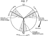
- Fig. 7 is a graph illustrating the target range of the cylinder stop position and a stop position of each of the stop-time compression stroke cylinder, the stop-time compression transition cylinder, and the stop-time expansion stroke cylinder corresponding thereto.
- Fig. 6 is a graph illustrating a relationship between the cylinder stop position and a minimum value of torque of the motor M that is required to start the engine E, which has been stopped at this cylinder stop position, (hereinafter appropriately referred to as starting torque).
- a horizontal axis of Fig. 6 also indicates positions of the stop-time compression stroke
- FIG. 7 illustrates the position of each of the cylinders 2 (the position of the piston 5 in each of the cylinders 2) such that the highest point of a circle is set as top dead center (TDC), the lowest point thereof is set as bottom dead center (BDC), and the position of the piston 5 moves to the retarded side as the target range moves clockwise.
- the cylinder stop position where the starting torque becomes minimum is a position indicated by a solid line in Fig. 6 , is a position at which the stop-time compression stroke cylinder is located at 60°CA before the compression top dead center (BTDCc), is a position at which the stop-time expansion stroke cylinder is located at 60°CA after the compression top dead center (ATDCc), and is a position at which the stop-time compression transition cylinder is at the intake bottom dead center (BDCi).
- the starting torque becomes minimum when the pistons 5 in the stop-time compression stroke cylinder and the stop-time expansion stroke cylinder are located at the same position with respect to the top dead center.
- the cylinder stop position at the time when this starting torque becomes minimum will be referred to as an optimum position P0.
- the target range of the cylinder stop position is a position at which the starting torque is equal to or lower than specified reference torque T1, and is set as a range from a first position P1 on an advanced side from the optimum position P0 to a second position P2 on the retarded side from the optimum position P0.
- the reference torque T1 is set to a value between a maximum value and a minimum value of the starting torque.
- the first position P1 is set at a position at which the position of the stop-time compression stroke cylinder is at 75°CA before the compression top dead center (BTDCc), the position of the stop-time compression transition cylinder is at 15°CA before the intake bottom dead center (BBDCi), and the position of the stop-time expansion stroke cylinder is at 45°CA after the compression top dead center (ATDCc).
- the second position P2 is set at a position at which the position of the stop-time compression stroke cylinder is at 40°CA before the compression top dead center (BTDCc), the position of the stop-time compression transition cylinder is at 20°CA after the intake bottom dead center (ABDCi), and the position of the stop-time expansion stroke cylinder is at 80°CA after the compression top dead center (ATDCc).
- Step S1 in the flowchart illustrated in Fig. 8 is executed after the engine stop control is executed.
- step S1 the controller 200 particularly determines whether the engine speed is reduced to be lower than a reference speed N2.
- the controller 200 particularly makes this determination on the basis of the detection result of the crank angle sensor SN1.
- the reference speed N2 is set in advance and stored in the controller 200. If the determination in step S1 is NO and it is determined that the engine speed is equal to or higher than the reference speed N2, the controller 200 particularly repeats step S1 and waits until the engine speed becomes lower than the reference speed N2. On the other hand, if the determination in step S1 is YES and the controller 200 particularly determines that the engine speed becomes lower than the reference speed N2, the processing proceeds to step S2.
- step S2 the controller 200 particularly retards a phase of the intake valve 11 by the intake S-VT 13a so as to retard intake valve close timing IVC, which is close timing of the intake valve 11, to first reference timing.
- the first reference timing is set in advance and stored in the controller 200.
- the first reference timing is set at timing on the retarded side from the intake valve close timing IVC immediately after execution of the engine stop control (immediately after execution of the control for fully closing the throttle valve 32) and on the advanced side from second reference timing, which will be described below.
- the first reference timing corresponds to the "pre-valve close timing" in the claims.
- step S3 the controller 200 particularly predicts engine stop timing, which is timing at which the engine E is stopped, and the cylinder stop position, that is, the position of each of the pistons 5 at the time when the engine E is stopped.
- the controller 200 particularly predicts the above timing and position on the basis of the detection value of the intake manifold pressure sensor SN3, the detection value of the crank angle sensor SN1, the detection value of the cam angle sensor SN2, and the like.
- step S4 the controller 200 particularly determines whether the engine is stopped after the piston 5 passes second compression top dead center on the basis of the prediction result in step S3.
- step S4 the controller 200 determines whether the engine is stopped after two pistons 5 respectively pass the compression top dead center.
- step S4 the controller 200 determines whether there are two cylinders that pass the compression top dead center (TDCc) in a period from a current time point to time at which the engine is stopped. Further particularly, the controller 200 determines whether one piston 5 passes the compression top dead center at one cylinder, and another piston 5 passes the top dead center at another cylinder.
- TDCc compression top dead center
- step S4 If the determination in step S4 is NO and it is determined that the engine E is not stopped at timing after the pistons 5 pass the two compression top dead centers (or the tow pistons 5 respectively pass the compression top dead center) from the current time point, the processing returns to step S3, and the controller 200 may continue to predict the engine stop timing and the cylinder stop position.
- step S4 determines that the engine is stopped after the pistons 5 passes the two compression top dead centers.
- step S5 the controller 200 particularly determines whether the cylinder stop position that is predicted in step S3 (hereinafter referred to as a predicted cylinder stop position) falls within an avoidance required range X1.
- the avoidance required range X1 is a range on the retarded side of a target range X0, and is set as a range from a state where the piston 5 in the stop-time compression stroke cylinder is located at a position on the most retarded side in the target range X0 (40°CA before the compression top dead center (BTDCc) corresponding to the second position P2) to a state where the piston 5 in the stop-time compression stroke cylinder reaches the compression top dead center (TDCc). That is, in step S5, it is determined whether a predicted stop position of the stop-time compression stroke cylinder is a position that is closer to the top dead center (the compression top dead center TDCc) than the target range thereof.
- step S6 the controller 200 particularly increases the opening degree of the throttle valve 32.
- the controller 200 may increases the opening degree of the throttle valve 32 such that an increase amount of the opening degree of the throttle valve 32 is increased as a shifting amount of the predicted cylinder stop position from the target range X0 (the second position P2) is increased.
- step S7 the processing proceeds to step S7.
- step S5 determines that the predicted cylinder stop position does not fall within the avoidance required range X1 (if it is determined that the predicted stop position of the stop-time compression stroke cylinder is not on the top dead center side from the target range X0), the processing proceeds to step S7.
- step S7 the controller 200 particularly resumes retardation of the phase of the intake valve 11, that is, retardation of the intake valve close timing IVC by the intake S-VT 13a. Further particularly, the controller 200 controls the intake S-VT 13a such that the phase of the intake valve 11 is retarded at a specified speed.
- step S7 is executed after steps S5, S6. However, step S5 and step S7 are executed almost simultaneously. Immediately after the determination in step S4 is YES and it is determined that the engine is stopped after the pistons 5 pass the two compression top dead centers, the controller 200 executes step S7.
- the above retardation speed is set to such a speed that, when the retardation of the phase of the intake valve 11 is started in association with the determination that the engine is stopped after the pistons 5 pass the two compression top dead centers (or the two pistons 5 pass the compression top dead center), the phase of the intake valve 11 reaches a phase in which the intake valve close timing IVC becomes the second reference timing.
- the second reference timing is set as timing on the most retarded side of timing that the intake valve close timing IVC can take, and the above speed is set to such a speed that the intake valve close timing IVC is changed from the first reference timing to the second reference timing over a period corresponding to 300°CA.
- step S4 the timing at which the determination Yes is made in above step S4, that is, the timing at which it is determined the engine is stopped after the pistons 5 pass the two compression top dead centers (or the two pistons 5 pass the compression top dead center) corresponds to the "specified timing" in the claims.
- step S8 the controller 200 particularly determines whether the intake valve close timing IVC has reached the second reference timing.
- the controller 200 may make this determination on the basis of the detection result of the cam angle sensor SN2.
- step S8 If the determination in step S8 is NO and it is determined that the intake valve close timing IVC has not reached the second reference timing, the processing returns to step S7, and the controller 200 continues the retardation of the phase of the intake valve 11.
- step S8 determines whether the intake valve close timing IVC has reached the second reference timing. If the determination in step S8 is YES and it is determined that the intake valve close timing IVC has reached the second reference timing, the controller 200 terminates the processing (the stop position control).
- Fig. 10 is a time chart schematically illustrating a temporal change in each parameter when the above stop position control is executed.
- Fig. 10 illustrates, in an order from top to bottom, time charts of the engine speed, the position of the piston 5 in the cylinder in the compression stroke, the phase of the intake valve 11, the opening degree of the throttle valve 32, and the intake manifold pressure.
- Fig. 10 also illustrates the temporal change in each of the parameters after the fuel cut.
- the engine speed is gradually reduced.
- the engine speed becomes equal to or lower than the throttle valve closing speed N1 at time t1.
- the throttle valve 32 starts being closed at time t1, and thereafter the throttle valve 32 is fully closed.
- the engine speed becomes lower than the reference speed N2 at time t2 after the throttle valve 32 is closed.
- the phase of the intake valve 11 is retarded at the time t2. More specifically, as described above, the controller 200 retards the phase of the intake valve 11 by the intake S-VT 13a so as to retard the intake valve close timing IVC to the first reference timing.
- the intake valve close timing IVC does not reach the first reference timing immediately but eventually reaches the first reference timing at time t3. Once reaching the first reference timing, the intake valve close timing IVC is maintained at the first reference timing for a while.
- the intake valve close timing IVC at this time is retarded such that the intake valve close timing IVC reaches the second reference timing at later timing than the intake valve close timing IVC of the stop-time compression stroke cylinder.
- the intake valve close timing IVC reaches the second reference timing at time t5 that is later than the intake valve close timing IVC of the fifth cylinder 2E as the stop-time compression stroke cylinder. After the time t5, the intake valve close timing IVC is maintained at the second reference timing. Then, at time t6 after the time t5, the engine E is completely stopped.
- the intake valve close timing IVC is retarded even after the intake valve (11) of the stop-time expansion stroke cylinder (2; 2A to 2F) is closed, and/or the intake valve close timing IVC is retarded until the intake valve (11) of the stop-time compression stroke cylinder (2; 2A to 2F) is closed or until the engine E is completely stopped.
- solid lines in FIG. 10 are those in an example of a case where it is determined that the predicted cylinder stop position is not the avoidance required range X1 at the time t4, at which it is determined that the engine E is stopped after the pistons 5 pass the two compression top dead centers. In this case, even after the time t4, the throttle valve 32 is maintained to be fully closed.
- broken lines in FIG. 10 are those in an example of a case where it is determined at the time t4 that the predicted cylinder stop position falls within the avoidance required range X1.
- the throttle valve 32 is opened at the time t4. Then, in this case, the intake manifold pressure is significantly increased along with opening of the throttle valve 32.
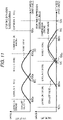
- Fig. 11 is a graph illustrating valve lifts of each of the intake valves 11 and each of the exhaust valves 12 in the stop-time compression stroke cylinder and the stop-time expansion stroke cylinder immediately before the engine stop. In the graph of the stop-time compression stroke cylinder illustrated in Fig.
- the crank angle from the intake bottom dead center (BDCi) to the intake valve close timing IVC that is, the retarded amount of the intake valve close timing IVC from the intake bottom dead center (BDCi) is larger for the stop-time compression stroke cylinder than for the stop-time expansion stroke cylinder.
- the intake valve close timing IVC is maintained at constant timing in the state where the intake manifold pressure is increased as described above, the intake amount of the stop-time compression stroke cylinder, whose intake stroke is performed after that of the stop-time expansion stroke cylinder, will become larger than the intake amount of the stop-time expansion stroke cylinder. Accordingly, in the case where the intake valve close timing IVC is maintained to be constant, a force that is applied to the piston 5 in the stop-time compression stroke cylinder from the intake air becomes larger than a force that is applied to the piston 5 in the stop-time expansion stroke cylinder from the intake air.
- the stop position of the stop-time compression stroke cylinder is located below the stop position of the stop-time expansion stroke cylinder.
- the cylinder stop positions are shifted to the advanced side from the target range X0.
- the intake manifold pressure is increased immediately before the engine stop is because a suction force of the intake air by the engine body 1 is reduced when the engine speed is reduced near 0.
- a pressure in the intake passage 30 becomes a negative pressure. Accordingly, in this case, the intake manifold pressure tends to be increased due to leakage of the intake air into the intake passage 30 from a portion around the throttle valve 32 or the like that is associated with the reduction in the suction force of the intake air by the engine body 1.
- the retarded amount from the intake bottom dead center (BDCi) at the intake valve close timing IVC of the stop-time compression stroke cylinder is set to be larger than that at the intake valve close timing IVC of the stop-time expansion stroke cylinder.
- the intake amount of the stop-time compression stroke cylinder immediately before the engine stop, it is possible to suppress the intake amount of the stop-time compression stroke cylinder from being increased in association with the increase in the intake manifold pressure by increasing the blow-back amount of the stop-time compression stroke cylinder to be larger than the blow-back amount of the intake air to the intake port 9 of the stop-time expansion stroke cylinder.
- the force applied to the piston 5 of the stop-time compression stroke cylinder from the intake air from becoming excessively larger than the force applied to the piston 5 of the stop-time expansion stroke cylinder from the intake air, and it is thus possible to suppress the stop-time compression stroke cylinder from being shifted to the bottom dead center side from the target range X0.
- the intake valve close timing IVC prior to the retardation of the intake valve close timing IVC in association with the determination that the engine E is stopped after the execution of the engine stop control and after the pistons 5 pass the two compression top dead centers, the intake valve close timing IVC is once retarded to the first reference timing. Accordingly, it is possible to reliably increase the retarded amount from the intake bottom dead center (BDCi) of the intake valve close timing IVC of the stop-time compression stroke cylinder immediately before the engine stop by avoiding such a situation where the intake valve close timing IVC of the stop-time compression stroke cylinder is not sufficiently retarded due to a delay in driving of the intake S-VT 13a. Thus, it is possible to further reliably set the cylinder stop position at the position within the target range X0.
- BDCi intake bottom dead center
- the opening degree of the throttle valve 32 is increased in the case where it is predicted that the stop position of the stop-time compression stroke cylinder is located on the top dead center side from the target range X0.
- the intake manifold pressure is increased as indicated by the broken line in Fig. 10 . Accordingly, it is possible to increase the intake amount of the stop-time compression stroke cylinder, whose intake stroke is performed later than the stop-time expansion stroke cylinder, and it is thus possible to suppress the piston 5 in the stop-time compression stroke cylinder from being lifted.
- a specific configuration is not limited to the above as long as this relationship of the retarded amounts is established.
- the intake S-VT 13a may be driven to retard the phase of the intake valve 11 after the intake valve close timing IVC of the stop-time expansion stroke cylinder immediately before the engine stop. In this way, the retarded amount of the stop-time compression stroke cylinder immediately before the engine stop may be increased to be larger than the retarded amount of the stop-time expansion stroke cylinder immediately before the engine stop.
- the timing at which the intake valve close timing IVC is once retarded to the first reference timing is not limited to the above timing as long as such timing falls within a period after the fuel cut and until the retardation of the phase of the intake valve 11 is resumed.
- this control for once retarding the intake valve close timing IVC to the first reference timing may be omitted.
- the number of cylinders in the engine E is not limited thereto and may be four or the like.
Abstract
Description
- The present invention relates to a stop position controller, particularly a stop position controller that is provided for an engine capable of being forcibly started by causing a crankshaft to rotate.
- Conventionally, in a vehicle on which an engine is mounted, in order to improve fuel efficiency, the engine is automatically stopped, and thereafter the engine is forcibly started by using start means.
- Here, in a multicylinder engine including plural cylinders, since torque that is requested to the start means in order to start the engine varies according to a position of each of the cylinders (a piston position in each of the cylinders) at an engine stop, it is required to set the position of each of the cylinders to a position suited for the start at the engine stop.
- To handle such a problem, for example, for the engine disclosed in
Patent document 1, the following control is executed immediately before the stop of the engine. That is, control is executed to increase an opening degree of a throttle valve after completion of air intake of a stop-time expansion stroke cylinder (a final expansion cylinder in Patent document 1) as a cylinder that is stopped in an expansion stroke, so as to increase an intake amount of a stop-time compression stroke cylinder (a final compression cylinder in Patent document 1) as a cylinder that is stopped in a compression stroke. - [Patent document 1]
JP-A-2013-60827 - Here, at time immediately before the stop of the engine, a pressure in an intake passage is increased in conjunction with a reduction in an engine speed. Accordingly, at the time immediately before the stop of the engine, the intake amount in the stop-time compression stroke cylinder tends to be larger than the intake amount in the stop-time expansion stroke cylinder whose intake stroke is terminated earlier than the stop-time compression stroke cylinder. In this way, in the case where, as in
Patent document 1, the opening degree of the throttle valve is simply increased immediately before the engine stop to increase the intake amount of the stop-time compression stroke cylinder, the intake amount of the stop-time compression stroke cylinder becomes excessive, which possibly shifts a position of the stop-time compression stroke cylinder to bottom dead center side from an appropriate position. More specifically, the intake amount of the stop-time compression stroke cylinder becomes excessively larger than the intake amount of the stop-time expansion stroke cylinder. Accordingly, a force by the intake air of the stop-time expansion stroke cylinder to push down a piston in the cylinder (in other words, a force of lifting the piston in the stop-time compression stroke cylinder) is insufficient for a force by the intake air of the stop-time compression stroke cylinder to push down the piston in the cylinder, which possibly shifts the position of the stop-time compression stroke cylinder to the bottom dead center side from the appropriate position. Thus, with the device disclosed inPatent document 1, it may be impossible to reduce the torque of the start means that is required to start the engine. - The present invention has been made in view of circumstances as described above and therefore has a purpose of reliably reducing torque of start means that is consumed for an engine start by controlling a position of each cylinder at an engine stop to a position suited for the start.
- In order to solve the above problem, the present invention is particularly a stop position controller provided for an engine including: plural cylinders; plural intake ports, each of which communicates with respective one of the cylinders; plural intake valves, each of which opens/closes respective one of the intake ports; fuel supply means that supplies fuel to each of the cylinders; a piston that is provided in each of the cylinders in a reciprocal manner; a crankshaft that rotates in an interlocking manner with reciprocating motion of the piston; and start means capable of forcibly starting the engine by causing the crankshaft to rotate. The stop position controller for an engine includes: intake valve close timing change means that collectively changes intake valve close timing as close timing of the plural intake valves; and control means that controls each section in the engine including the fuel supply means and the intake valve close timing change means. When a specified engine stop condition is satisfied, the control means performs fuel cut to stop a fuel supply into the cylinder by the fuel supply means and, after the fuel cut, controls the intake valve close timing change means such that a retarded amount of the intake valve close timing before or immediately before a stop of a stop-time compression stroke cylinder, which is the cylinder stopped in a compression stroke, from intake bottom dead center is larger than a retarded amount of the intake valve close timing before or immediately before a stop of a stop-time expansion stroke cylinder, which is the cylinder stopped in an expansion stroke, from the intake bottom dead center.
- In the above stop position controller, after the fuel cut, the retarded amount of the intake valve close timing immediately before the stop of the stop-time compression stroke cylinder from the intake bottom dead center is set to be larger than the retarded amount of the intake valve close timing immediately before the stop of the stop-time expansion stroke cylinder from the intake bottom dead center. When the retarded amount of the intake valve close timing from the intake bottom dead center is increased, a blow-back amount of intake air from inside of the cylinder to the intake port is increased, and an intake amount in the cylinder is reduced. Thus, according to the present invention, it is possible to suppress an increase in the intake amount of the stop-time compression stroke cylinder, which is likely to be increased in association with a pressure increase in an intake passage immediately before an engine stop, and it is thus possible to prevent the intake amount of the stop-time compression stroke cylinder from becoming excessively larger than the intake amount of the stop-time expansion stroke cylinder. Therefore, it is possible to prevent a position of the stop-time compression stroke cylinder from being shifted to the bottom dead center side from an appropriate position. In other words, it is possible to set the stop position of each of the cylinders including the stop-time compression stroke cylinder (the position of each of the cylinders at the engine stop) to a position suited for the start, and it is thus possible to reliably reduce torque of the start means consumed for the engine start.
- In the above configuration, particularly, in the case where an engine speed becomes lower than a specified reference speed after the fuel cut, the control means retards the intake valve close timing to specified pre-valve close timing by the intake valve close timing change means, and after the intake valve close timing reaches the pre-valve close timing and specified timing arrives, retards the intake valve close timing from the pre-valve close timing by the intake valve close timing change means.
- According to this configuration, it is possible to prevent such a situation where the intake valve close timing of the stop-time compression stroke cylinder immediately before the engine stop is not sufficiently retarded due to a response delay of the intake valve close timing change means. In other words, it is possible to secure the retarded amount of the intake valve close timing of the stop-time compression stroke cylinder immediately before the engine stop from the intake bottom dead center. Therefore, it is possible to reliably increase the blow-back amount of the intake air from the inside of the stop-time compression stroke cylinder to the intake port and reliably suppress the increase in the intake amount of the stop-time compression stroke cylinder.
- In the above configuration, particularly, the engine includes a throttle valve that opens/closes an intake passage communicating with the plural intake ports, and the control means predicts a stop position of the stop-time compression stroke cylinder after the fuel cut and increases an opening degree of the throttle valve when predicting that the stop position of the stop-time compression stroke cylinder is on a top dead center side from a specified target range.
- As described above, the present invention can increase a possibility of setting the stop position of each of the cylinders at the position suited for the start. However, depending on a degree of the reduction in the engine speed immediately before the engine stop, and the like, there is a possibility that the piston in the stop-time compression stroke cylinder is not sufficiently lifted immediately before the engine stop and thus the stop position of the cylinder is located on a top dead center side from the target range. Meanwhile, in this configuration, the opening degree of the throttle valve is increased in the case where it is predicted that the stop position of the stop-time compression stroke cylinder is located on the top dead center side from the target range. When the opening degree of the throttle valve is increased, a pressure in the intake passage is increased. Accordingly, it is possible to increase the intake amount of the stop-time compression stroke cylinder, whose intake stroke is performed later than the stop-time expansion stroke cylinder, and it is thus possible to suppress the piston in the stop-time compression stroke cylinder from being lifted. Thus, according to this configuration, it is possible to suppress the stop position of the stop-time compression stroke cylinder from being shifted to the top dead center side from the target range, and it is thus possible to further reliably set the stop position of each of the cylinders within the target range, that is, a range suited for the start and further reliably reduce the torque of the start means consumed for the engine start.
- Here, it has been found that, in the case where the stop position of the stop-time compression stroke cylinder is set to be equal to or larger than 40 degrees before compression top dead center and equal to or smaller than 75 degrees before the compression top dead center in crank angle in a six-cylinder engine having six cylinders, the engine can be started while torque of the start means is suppressed to be equal to or lower than a specified value.
- In this way, in the configuration that the engine has the six cylinders, the target range is particularly set to a range of 40 degrees or larger before compression top dead center and 75 degrees or smaller before the compression top dead center in crank angle. Further particularly, the target range is a range from 40 to 75 degrees before the compression top dead center in crank angle.
- According to the stop position controller as described above, it is possible to reliably reduce the torque of the start means consumed for the engine start by controlling the position of each of the cylinders at the engine stop to the position suited for the start.
-
- [
Fig. 1] Fig. 1 is a schematic configuration diagram of a vehicle on which an engine, to which a stop position controller according to an embodiment of the present invention is applied, is mounted. - [
Fig. 2] Fig. 2 is a schematic configuration view of the engine. - [
Fig. 3] Fig. 3 is a schematic cross-sectional view of an engine body. - [
Fig. 4] Fig. 4 is a chart illustrating strokes that are performed in each cylinder of the engine. - [
Fig. 5] Fig. 5 is a block diagram illustrating a control system for the engine. - [
Fig. 6] Fig. 6 is a graph illustrating a relationship between a cylinder stop position and motor torque required for an engine start. - [
Fig. 7] Fig. 7 is a graph illustrating a target range of the cylinder stop position. - [
Fig. 8] Fig. 8 is a flowchart illustrating a specific procedure of stop position control. - [
Fig. 9] Fig. 9 is a graph illustrating an avoidance required range of the cylinder stop position. - [
Fig. 10] Fig. 10 is a time chart illustrating a temporal change in each parameter when the stop position control is executed. - [
Fig. 11] Fig. 11 is a view illustrating valve lifts of a stop-time expansion stroke cylinder and a stop-time compression stroke cylinder immediately before an engine stop during execution of the stop position control. - [
Fig. 12] Fig. 12 is a graph illustrating a stop position of each of the cylinders at the time when the cylinder stop position of the stop-time compression stroke cylinder is shifted to bottom dead center side from a target range. -
Fig. 1 is a schematic configuration diagram of avehicle 100 on which an engine E, to which a stop position controller for an engine according to an embodiment of the present invention is applied, is mounted. In this embodiment, thevehicle 100 may be a hybrid vehicle that includes the engine E and a motor M as drive sources of the vehicle 100 (a wheel 101). The motor M corresponds to the "start means" in the claims. - As illustrated in
Fig. 1 , thevehicle 100 particularly includes, in addition to thewheel 101, the engine E, and the motor M; aclutch 102 that couples an output shaft of the engine E and a rotary shaft of the motor M in an engageable/disengageable manner; abattery 103 that exchanges electric power with the motor M; atransmission 104 that is coupled to the motor M; and apower transmission device 105 that includes adriveshaft 106 coupled to thewheel 101, a differential gear, and the like and couples thetransmission 104 and thedriveshaft 106. -
Fig. 2 is a schematic configuration view of the engine E. The engine E particularly includes: anengine body 1; anintake passage 30 through which intake air to be introduced into theengine body 1 flows; anexhaust passage 40 through which exhaust gas discharged from theengine body 1 flows; and anEGR device 44 that circulates EGR gas as some of the exhaust gas flowing through theexhaust passage 40 into theintake passage 30. The engine E may also include aturbocharger 46 having: aturbine 48 that is provided in theexhaust passage 40; and acompressor 47 that is rotationally driven by theturbine 48 provided in theintake passage 30. The engine E in this embodiment is a four-stroke diesel engine and is driven when being supplied with fuel that has diesel fuel as a main component. - The
engine body 1 particularly has: acylinder block 3 that is formed with acylinder 2; and acylinder head 4 that covers thecylinder block 3. -
Fig. 3 is a schematic cross-sectional view of theengine body 1. As illustrated inFig. 3 , the engine E in this embodiment is particularly an in-line six-cylinder engine. The engine body 1 (in detail, the cylinder block 3) is formed with the six cylinders 2 (afirst cylinder 2A, asecond cylinder 2B, a third cylinder 2C, afourth cylinder 2D, afifth cylinder 2E, and asixth cylinder 2F in an order from one side along an arrangement direction of the cylinders 2) that are aligned in a line. - A
piston 5 is accommodated in each of thecylinders 2 in a reciprocal manner. Acombustion chamber 6 is defined above thepiston 5 in each of thecylinders 2. Each of thepistons 5 is coupled to acrankshaft 7 via a connectingrod 8. Thecrankshaft 7 rotates about a center axis thereof according to reciprocating motion of each of thepistons 5. - An
injector 15 that injects the fuel into the cylinder 2 (the combustion chamber 6) may be attached to thecylinder head 4 for each of thecylinder 2, and the oneinjector 15 is provided for each of thecylinders 2. Thepiston 5 reciprocates when air-fuel mixture of the supplied fuel and supplied air is burned in thecombustion chamber 6 and thepiston 5 is pushed down by an expansion force generated by the combustion. Theinjector 15 corresponds to the "fuel supply means" in the claims. - The
cylinder head 4 is provided with, for each of the cylinders 2: anintake port 9 used to introduce the intake air to each of the cylinders 2 (the combustion chamber 6); anintake valve 11 that open and/or close theintake port 9; anexhaust port 10 used to discharge the exhaust gas, which is generated in each of the cylinders 2 (the combustion chamber 6); and anexhaust valve 12 that open and/or close theexhaust port 10. A valve type of theengine body 1 is a four-valve type having two intake valves and two exhaust valves. For each of thecylinders 2, two each of theintake ports 9 and theexhaust ports 10 are provided. For each of thecylinders 2, two each of theintake valves 11 and theexhaust valves 12 are provided. -
Fig. 4 is a chart illustrating strokes that are performed in each of thecylinders 2. As described above, the engine E is the four-stroke engine. Thus, in each of thecylinders 2, an intake stroke → a compression stroke → an expansion stroke → and an exhaust stroke are sequentially performed in this order. The engine E is the in-line six-cylinder engine. In this way, thepiston 5, which is provided in each of thecylinders 2A to 2F, reciprocates with a phase difference of 120°CA (120° in a crank angle), and the combustion may occur e.g. in an order of thefirst cylinder 2A → thefifth cylinder 2E → the third cylinder 2C → thesixth cylinder 2F → thesecond cylinder 2B → thefourth cylinder 2D every 120°CA. - Here, the intake, compression, expansion, and exhaust strokes described in the present specification refer to periods that are acquired by dividing one combustion cycle, that is, a period in which the
crankshaft 7 rotates twice (360°CA) into four equal periods by the crank angle, and respectively refer to periods in which intake, compression, expansion, and exhaust are primarily performed. - More specifically, the intake stroke described in the present specification does not refer to a period from time at which the
intake valve 11 actually starts being opened to time at which theintake valve 11 is closed, but refers to a period in which thepiston 5 is located between exhaust top dead center TDCe and intake bottom dead center BDCi. - The compression stroke refers to a period in which the
piston 5 is located between the intake bottom dead center BDCi and compression top dead center TDCc. - The expansion stroke refers to a period in which the
piston 5 is located between the compression top dead center TDCc and expansion bottom dead center BDCe. - The exhaust stroke refers to a period in which the
piston 5 is located between the expansion bottom dead center BDCe and the exhaust top dead center TDCe. - Here, the compression top dead center TDCc is a position on the uppermost side (a near side of the cylinder head 4) in a reciprocation range of the
piston 5 and is a position that thepiston 5 reaches after theintake valve 11 is closed and before theexhaust valve 12 is opened. Each of the expansion bottom dead center BDCe, the exhaust top dead center TDCe, and the intake bottom dead center BDCi is a position of thepiston 5 at the time when thecrankshaft 7 rotates positively for 180°CA, 360°CA, and 540°CA from a state where thepiston 5 is located at the compression top dead center TDCc. Hereinafter, the position of thepiston 5 may appropriately be described as a position of thecylinder 2. - The
intake valve 11 in each of thecylinders 2 is particularly driven by avalve mechanism 13 that includes an intake camshaft disposed in thecylinder head 4. Thevalve mechanism 13 for theintake valves 11 particularly includes an intake Sequential Valve Timing (S-VT) 13a capable of changing open and/or close timing of theintake valves 11 collectively. Similarly, theexhaust valve 12 in each of thecylinders 2 is driven by avalve mechanism 14 that includes an exhaust camshaft disposed in thecylinder head 4. Thevalve mechanism 14 for theexhaust valves 12 particularly includes an exhaust S-VT 14a capable of changing open and/or close timing of theexhaust valves 12 collectively. - The intake S-
VT 13a (the exhaust S-VT 14a) may be a so-called phase-type variable mechanism, and simultaneously change open initiation timing IVO (EVO) and close timing IVC (EVC) of each of the intake valves 11 (each of the exhaust valves 12) by the same amount. The intake S-VT 13a corresponds to the "intake valve close timing change means" of the claim. - The
intake passage 30 is connected to one side surface of thecylinder head 4 so as to communicate with theintake port 9. In theintake passage 30, anair cleaner 31, thecompressor 47, athrottle valve 32, anintercooler 33, and asurge tank 34 are particularly provided in this order from an upstream side. - The
compressor 47 is rotationally driven by theturbine 48 as described above and compresses (supercharges) the air that flows through thecompressor 47. The air that has been compressed by thecompressor 47 and then cooled by theintercooler 33 is introduced into the cylinder 2 (the combustion chamber 6). - The
throttle valve 32 is a valve capable of opening and/or closing theintake passage 30. An amount of air that flows through theintake passage 30, and hence, an amount of the intake air that is introduced into the cylinder 2 (the combustion chamber 6) varies according to an opening degree of thethrottle valve 32. - The
exhaust passage 40 is connected to another side surface of thecylinder head 4 so as to communicate with theexhaust port 10. Theexhaust passage 40 is particularly provided with theturbine 48 and anexhaust purifier 41 for purifying the exhaust gas in this order from an upstream side. Theexhaust purifier 41 includes a three-way catalyst 42 and a diesel particulate filter (DPF) 43. Theturbine 48 rotates by receiving energy of the exhaust gas flowing through theexhaust passage 40, and thecompressor 47 rotates in conjunction therewith. - The
EGR device 44 particularly include: anEGR passage 44A that connects theexhaust passage 40 and theintake passage 30; and anEGR valve 45 that is provided in theEGR passage 44A. TheEGR passage 44A connects a portion of theexhaust passage 40 on an upstream side of theturbine 48 and a portion between theintercooler 33 and thesurge tank 34 in theintake passage 30. TheEGR valve 45 is a valve capable of opening/closing theEGR passage 44A. An amount of EGR gas that is circulated into theintake passage 30, and hence, an amount of the EGR gas that is introduced into the cylinder 2 (the combustion chamber 6) varies according to an opening degree of theEGR valve 45. In theEGR passage 44A, an EGR cooler (not illustrated) is provided to cool the exhaust gas (the EGR gas) that is circulated from theexhaust passage 40 into theintake passage 30 by heat exchange. -
Fig. 5 is a block diagram illustrating a control system of thevehicle 100. Acontroller 200 illustrated inFig. 5 may be a microprocessor that integrally controls the motor M, the engine E, and the like, and is particularly constructed of a CPU, ROM, RAM, which are well-known, and the like. Thecontroller 200 corresponds to the "control means" in the claims. - The
controller 200 receives detection signals from one or various sensors that are provided in thevehicle 100. - Particularly, in the
cylinder block 3 of the engine E, a crank angle sensor SN1 is provided to detect a rotation angle of thecrankshaft 7, that is, an engine speed. In thecylinder head 4 of the engine E, a cam angle sensor SN2 is provided to detect an angle of an intake cam that is provided in theintake valve mechanism 13. Thecontroller 200 determines which cylinder is in what stroke on the basis of the detection signal of the cam angle sensor SN2 and the detection signal of the crank angle sensor SN1. In a portion of theintake passage 30 of the engine E on a downstream side of thethrottle valve 32, an intake manifold pressure sensor SN3 is provided to detect a pressure of the intake air flowing through this portion. Hereinafter, the pressure of the intake air that flows through the portion of theintake passage 30 on the downstream side of thethrottle valve 32 will be referred to as an intake manifold pressure. The intake air described in the present specification refers to the gas that is introduced into the cylinder 2 (the combustion chamber 6) and, when the EGR gas is introduced in addition to the air into thecylinder 2, refers to gas containing the EGR gas and the air. In theexhaust passage 40 of the engine E, an exhaust O2 sensor SN4 is provided to detect exhaust O2 concentration that is concentration of oxygen contained in the exhaust gas flowing through theexhaust passage 40. The exhaust O2 sensor SN4 is arranged between theturbine 48 and theexhaust purifier 41. Thevehicle 100 is also provided with: a motor rotational speed sensor SN5 that detects a rotational speed of the motor M; an accelerator operation amount sensor SN6 that detects an accelerator operation amount that is an operation amount of an accelerator pedal operated by a driver who drives thevehicle 100; a vehicle speed sensor SN7 that detects a vehicle speed; and the like. Thecontroller 200 sequentially receives the information detected by these sensors SN1 to SN7. - The
controller 200 makes one or various determinations, calculations, and the like on the basis of the input information from each of the sensors to control sections of the engine E, such as the intake S-VT 13a, the exhaust S-VT 14a, theinjector 15, thethrottle valve 32, and theEGR valve 45, the motor M, the clutch 102, and the like. - In this embodiment, the
intake valve 11 is particularly configured to be always closed on a retarded side from the intake bottom dead center BDCi, i.e., later than the intake bottom dead center BDCi, during operation of the engine E, and thecontroller 200 controls the intake S-VT 13a to achieve this. - In addition, in this embodiment, a basic travel mode of the
vehicle 100 may be set to an EV mode in which thewheel 101 is driven only by the motor M, and the mode may be switched to an engine drive mode in which the engine E is driven only when the output of the motor M alone is insufficient, or the like. Thecontroller 200 particularly switches the travel mode on the basis of the vehicle speed and the like. - Particularly, the
controller 200 determines, from a travel state of thevehicle 100 and an operation state of the accelerator pedal, whether an engine start condition as a condition to start the engine E is satisfied or whether an engine stop condition as a condition to stop the engine E is satisfied. - For example, the
controller 200 determines that the engine start condition is satisfied when, during the stop of the engine E, the vehicle speed becomes equal to or higher than a specified engine start speed and the operation amount of the accelerator pedal becomes equal to or larger than a specified engine start operation amount. - Meanwhile, the
controller 200 determines that the engine stop condition is satisfied when, during driving of the engine E, the vehicle speed becomes lower than a specified engine stop speed or the operation amount of the accelerator pedal becomes smaller than a specified engine stop operation amount. - The
controller 200 particularly sequentially determine whether each of the above conditions is satisfied on the basis of detection results of the vehicle speed sensor SN7 and the accelerator operation amount sensor SN6, and the like. - If determining that the engine start condition is satisfied, the
controller 200 particularly executes engine start control to start the engine E. In the engine start control, thecontroller 200 first shifts the clutch 102 from a disengaged state to an engaged state. When the clutch 102 is brought into the engaged state, the output of the motor M is transmitted to the engine E. In this way, the engine E is forcibly and rotationally driven by the motor M. That is, the engine E starts cranking. When cranking starts, next, thecontroller 200 may inject the first fuel from theinjector 15 during the compression stroke of thecylinder 2, which has been stopped near the intake bottom dead center BDCi, to cause self-ignited combustion thereof. Thereafter, the engine start control is shifted to normal engine control, and thecontroller 200 sequentially injects the fuel from theinjector 15 into each of thecylinders 2. Here, as described above, the clutch 102 is brought into the engaged state. In this way, drive power of the engine E is transmitted to thewheel 101 via the motor M, thetransmission 104, and the like. - Meanwhile, if determining that the engine stop condition is satisfied, the
controller 200 particularly executes engine stop control to stop the engine E. In the engine stop control, thecontroller 200 first performs fuel cut to stop the fuel supply from theinjector 15 to each of thecylinders 2. By stopping the fuel supply, the engine speed is reduced, and the engine is eventually stopped. - Here, when the engine speed becomes low, the
engine body 1 and an engine mount that supports theengine body 1 possibly resonate and increase vibration of theengine body 1. Thus, as the engine stop control, thecontroller 200 may execute control for fully closing thethrottle valve 32. In other words, the engine speed may be promptly reduced by fully closing thethrottle valve 32, so as to shorten a period in which the engine speed becomes a resonance speed. More specifically, in the case where the engine speed becomes equal to or lower than a specified throttle valve closing speed N1 after the fuel cut, thecontroller 200 closes thethrottle valve 32 until thethrottle valve 32 is fully closed. In addition, in the case where the engine E is stopped (the speed of the engine E becomes 0) at the time when the engine stop condition is satisfied, thecontroller 200 may switch the clutch 102 from the engaged state to the disengaged state. - Next, a description will be made on the stop position control that is particularly executed by the
controller 200 after the engine stop control is executed, that is, after the fuel cut is performed and thethrottle valve 32 may be fully closed. The stop position control is control for setting the position of each of the cylinders 2 (thepiston 5 in each of the cylinders 2) during the stop of the engine E within a specified target range. In other words, the stop position control may control the crank angle at each of thecylinders 2. - Hereinafter, a time in which the engine E is stopped, in detail, a time in which the engine speed is 0 and the engine E is completely stopped may simply be referred to as an engine stop time. In addition, the position of each of the cylinders 2 (the position of the
piston 5 in each of the cylinders 2) in the engine stop time may be referred to as a cylinder stop position. - In the embodiment, the cylinder whose stroke in the engine stop time (when the engine E is completely stopped) is the compression stroke and/or in which the position of the
piston 5 is located within a range from the compression top dead center (TDCc) to 120°CA before the compression top dead center (BTDCc) may be referred to as a stop-time compression stroke cylinder. - In addition, the cylinder whose combustion order is one stroke before that of the stop-time compression stroke cylinder, whose stroke at the engine stop (when the engine E is completely stopped) is the expansion stroke, and/or in which the position of the
piston 5 falls within a range from the compression top dead center (TDCc) to 120°CA after the compression top dead center (ATDCc) may be referred to as a stop-time expansion stroke cylinder. - Furthermore, the cylinder whose combustion order is one stroke after that of the stop-time compression stroke cylinder, whose stroke at the engine stop (when the engine E is completely stopped) is the intake stroke or the compression stroke, and/or in which the position of the
piston 5 falls within a range from 60°CA before intake bottom dead center (BBDCi) to 60°CA after the intake bottom dead center (ABDCi) may be referred to as a stop-time compression transition cylinder. -
Fig. 6 is a graph illustrating a relationship between the cylinder stop position and a minimum value of torque of the motor M that is required to start the engine E, which has been stopped at this cylinder stop position, (hereinafter appropriately referred to as starting torque). A horizontal axis ofFig. 6 also indicates positions of the stop-time compression stroke cylinder, the stop-time compression transition cylinder, and the stop-time expansion stroke cylinder.Fig. 7 is a graph illustrating the target range of the cylinder stop position and a stop position of each of the stop-time compression stroke cylinder, the stop-time compression transition cylinder, and the stop-time expansion stroke cylinder corresponding thereto.Fig. 7 illustrates the position of each of the cylinders 2 (the position of thepiston 5 in each of the cylinders 2) such that the highest point of a circle is set as top dead center (TDC), the lowest point thereof is set as bottom dead center (BDC), and the position of thepiston 5 moves to the retarded side as the target range moves clockwise. - As illustrated in
Fig. 6 , the starting torque varies by the cylinder stop position. The cylinder stop position where the starting torque becomes minimum is a position indicated by a solid line inFig. 6 , is a position at which the stop-time compression stroke cylinder is located at 60°CA before the compression top dead center (BTDCc), is a position at which the stop-time expansion stroke cylinder is located at 60°CA after the compression top dead center (ATDCc), and is a position at which the stop-time compression transition cylinder is at the intake bottom dead center (BDCi). In other words, the starting torque becomes minimum when thepistons 5 in the stop-time compression stroke cylinder and the stop-time expansion stroke cylinder are located at the same position with respect to the top dead center. Hereinafter, the cylinder stop position at the time when this starting torque becomes minimum will be referred to as an optimum position P0. - The target range of the cylinder stop position is a position at which the starting torque is equal to or lower than specified reference torque T1, and is set as a range from a first position P1 on an advanced side from the optimum position P0 to a second position P2 on the retarded side from the optimum position P0. The reference torque T1 is set to a value between a maximum value and a minimum value of the starting torque. Corresponding to the above, the first position P1 is set at a position at which the position of the stop-time compression stroke cylinder is at 75°CA before the compression top dead center (BTDCc), the position of the stop-time compression transition cylinder is at 15°CA before the intake bottom dead center (BBDCi), and the position of the stop-time expansion stroke cylinder is at 45°CA after the compression top dead center (ATDCc). Meanwhile, the second position P2 is set at a position at which the position of the stop-time compression stroke cylinder is at 40°CA before the compression top dead center (BTDCc), the position of the stop-time compression transition cylinder is at 20°CA after the intake bottom dead center (ABDCi), and the position of the stop-time expansion stroke cylinder is at 80°CA after the compression top dead center (ATDCc).
- A description will be made on a specific procedure of the stop position control with reference to a flowchart in
Fig. 8 . Step S1 in the flowchart illustrated inFig. 8 is executed after the engine stop control is executed. - In step S1, the
controller 200 particularly determines whether the engine speed is reduced to be lower than a reference speed N2. Thecontroller 200 particularly makes this determination on the basis of the detection result of the crank angle sensor SN1. The reference speed N2 is set in advance and stored in thecontroller 200. If the determination in step S1 is NO and it is determined that the engine speed is equal to or higher than the reference speed N2, thecontroller 200 particularly repeats step S1 and waits until the engine speed becomes lower than the reference speed N2. On the other hand, if the determination in step S1 is YES and thecontroller 200 particularly determines that the engine speed becomes lower than the reference speed N2, the processing proceeds to step S2. - In step S2, the
controller 200 particularly retards a phase of theintake valve 11 by the intake S-VT 13a so as to retard intake valve close timing IVC, which is close timing of theintake valve 11, to first reference timing. The first reference timing is set in advance and stored in thecontroller 200. The first reference timing is set at timing on the retarded side from the intake valve close timing IVC immediately after execution of the engine stop control (immediately after execution of the control for fully closing the throttle valve 32) and on the advanced side from second reference timing, which will be described below. The first reference timing corresponds to the "pre-valve close timing" in the claims. - Next, in step S3, the
controller 200 particularly predicts engine stop timing, which is timing at which the engine E is stopped, and the cylinder stop position, that is, the position of each of thepistons 5 at the time when the engine E is stopped. Thecontroller 200 particularly predicts the above timing and position on the basis of the detection value of the intake manifold pressure sensor SN3, the detection value of the crank angle sensor SN1, the detection value of the cam angle sensor SN2, and the like. After step S3, the processing proceeds to step S4. - In step S4, the
controller 200 particularly determines whether the engine is stopped after thepiston 5 passes second compression top dead center on the basis of the prediction result in step S3. - Further particularly, in step S4, the
controller 200 determines whether the engine is stopped after twopistons 5 respectively pass the compression top dead center. - Further particularly, in step S4, the
controller 200 determines whether there are two cylinders that pass the compression top dead center (TDCc) in a period from a current time point to time at which the engine is stopped. Further particularly, thecontroller 200 determines whether onepiston 5 passes the compression top dead center at one cylinder, and anotherpiston 5 passes the top dead center at another cylinder. - If the determination in step S4 is NO and it is determined that the engine E is not stopped at timing after the
pistons 5 pass the two compression top dead centers (or thetow pistons 5 respectively pass the compression top dead center) from the current time point, the processing returns to step S3, and thecontroller 200 may continue to predict the engine stop timing and the cylinder stop position. - On the other hand, if the determination in step S4 is YES and the
controller 200 determines that the engine is stopped after thepistons 5 passes the two compression top dead centers, the processing proceeds to step S5. - In step S5, the
controller 200 particularly determines whether the cylinder stop position that is predicted in step S3 (hereinafter referred to as a predicted cylinder stop position) falls within an avoidance required range X1. As illustrated inFig. 9 , the avoidance required range X1 is a range on the retarded side of a target range X0, and is set as a range from a state where thepiston 5 in the stop-time compression stroke cylinder is located at a position on the most retarded side in the target range X0 (40°CA before the compression top dead center (BTDCc) corresponding to the second position P2) to a state where thepiston 5 in the stop-time compression stroke cylinder reaches the compression top dead center (TDCc). That is, in step S5, it is determined whether a predicted stop position of the stop-time compression stroke cylinder is a position that is closer to the top dead center (the compression top dead center TDCc) than the target range thereof. - If the determination in step S5 is YES and it is determined that the predicted cylinder stop position falls within the avoidance required range X1 (if it is determined that the predicted stop position of the stop-time compression stroke cylinder is on the top dead center side from the target range X0), in step S6, the
controller 200 particularly increases the opening degree of thethrottle valve 32. In this embodiment, thecontroller 200 may increases the opening degree of thethrottle valve 32 such that an increase amount of the opening degree of thethrottle valve 32 is increased as a shifting amount of the predicted cylinder stop position from the target range X0 (the second position P2) is increased. After step S6, the processing proceeds to step S7. - On the other hand, if the determination in step S5 is NO and the
controller 200 determines that the predicted cylinder stop position does not fall within the avoidance required range X1 (if it is determined that the predicted stop position of the stop-time compression stroke cylinder is not on the top dead center side from the target range X0), the processing proceeds to step S7. - In step S7, the
controller 200 particularly resumes retardation of the phase of theintake valve 11, that is, retardation of the intake valve close timing IVC by the intake S-VT 13a. Further particularly, thecontroller 200 controls the intake S-VT 13a such that the phase of theintake valve 11 is retarded at a specified speed. Here, in the flowchart illustrated inFIG. 8 , step S7 is executed after steps S5, S6. However, step S5 and step S7 are executed almost simultaneously. Immediately after the determination in step S4 is YES and it is determined that the engine is stopped after thepistons 5 pass the two compression top dead centers, thecontroller 200 executes step S7. - The above retardation speed is set to such a speed that, when the retardation of the phase of the
intake valve 11 is started in association with the determination that the engine is stopped after thepistons 5 pass the two compression top dead centers (or the twopistons 5 pass the compression top dead center), the phase of theintake valve 11 reaches a phase in which the intake valve close timing IVC becomes the second reference timing. For example, the second reference timing is set as timing on the most retarded side of timing that the intake valve close timing IVC can take, and the above speed is set to such a speed that the intake valve close timing IVC is changed from the first reference timing to the second reference timing over a period corresponding to 300°CA. After step S5, the processing proceeds to step S6. Here, the timing at which the determination Yes is made in above step S4, that is, the timing at which it is determined the engine is stopped after thepistons 5 pass the two compression top dead centers (or the twopistons 5 pass the compression top dead center) corresponds to the "specified timing" in the claims. - In step S8, the
controller 200 particularly determines whether the intake valve close timing IVC has reached the second reference timing. Thecontroller 200 may make this determination on the basis of the detection result of the cam angle sensor SN2. - If the determination in step S8 is NO and it is determined that the intake valve close timing IVC has not reached the second reference timing, the processing returns to step S7, and the
controller 200 continues the retardation of the phase of theintake valve 11. - On the other hand, if the determination in step S8 is YES and it is determined that the intake valve close timing IVC has reached the second reference timing, the
controller 200 terminates the processing (the stop position control). -
Fig. 10 is a time chart schematically illustrating a temporal change in each parameter when the above stop position control is executed.Fig. 10 illustrates, in an order from top to bottom, time charts of the engine speed, the position of thepiston 5 in the cylinder in the compression stroke, the phase of theintake valve 11, the opening degree of thethrottle valve 32, and the intake manifold pressure.Fig. 10 also illustrates the temporal change in each of the parameters after the fuel cut. - As illustrated in
Fig. 10 , after the fuel cut is performed, the engine speed is gradually reduced. In the example illustrated inFig. 10 , the engine speed becomes equal to or lower than the throttle valve closing speed N1 at time t1. In association therewith, thethrottle valve 32 starts being closed at time t1, and thereafter thethrottle valve 32 is fully closed. - In the example illustrated in
Fig. 10 , the engine speed becomes lower than the reference speed N2 at time t2 after thethrottle valve 32 is closed. In association therewith, the phase of theintake valve 11 is retarded at the time t2. More specifically, as described above, thecontroller 200 retards the phase of theintake valve 11 by the intake S-VT 13a so as to retard the intake valve close timing IVC to the first reference timing. - Here, there is a delay in the phase change of the
intake valve 11. Thus, the intake valve close timing IVC does not reach the first reference timing immediately but eventually reaches the first reference timing at time t3. Once reaching the first reference timing, the intake valve close timing IVC is maintained at the first reference timing for a while. - In the example illustrated in
Fig. 10 , at time t4 after the time t3, it is determined that the engine E is stopped after thepistons 5 pass the two compression top dead centers. More specifically, in the example illustrated inFig. 10 , the engine E is stopped after thefourth cylinder 2D and thefirst cylinder 2A pass the compression top dead center (TDCc) and before thefifth cylinder 2E reaches the compression top dead center (TDCc) (without thefifth cylinder 2E reaching the compression top dead center (TDCc)), and it is determined that the engine E is stopped after thepistons 5 pass the two compression top dead center at the time t4 immediately after thesecond cylinder 2B, whose combustion order is one stroke before that of thefourth cylinder 2D passes the compression top dead center (TDCc). - When it is determined that the engine E is stopped after the
pistons 5 pass the two compression top dead centers, in association therewith, at the time t4, the retardation of the phase of theintake valve 11, that is, the retardation of the intake valve close timing IVC is resumed. - As described above, the intake valve close timing IVC at this time is retarded such that the intake valve close timing IVC reaches the second reference timing at later timing than the intake valve close timing IVC of the stop-time compression stroke cylinder.
- In the example illustrated in
Fig. 10 , the intake valve close timing IVC reaches the second reference timing at time t5 that is later than the intake valve close timing IVC of thefifth cylinder 2E as the stop-time compression stroke cylinder. After the time t5, the intake valve close timing IVC is maintained at the second reference timing. Then, at time t6 after the time t5, the engine E is completely stopped. - In other words, the intake valve close timing IVC is retarded even after the intake valve (11) of the stop-time expansion stroke cylinder (2; 2A to 2F) is closed, and/or the intake valve close timing IVC is retarded until the intake valve (11) of the stop-time compression stroke cylinder (2; 2A to 2F) is closed or until the engine E is completely stopped.
- Here, solid lines in
FIG. 10 are those in an example of a case where it is determined that the predicted cylinder stop position is not the avoidance required range X1 at the time t4, at which it is determined that the engine E is stopped after thepistons 5 pass the two compression top dead centers. In this case, even after the time t4, thethrottle valve 32 is maintained to be fully closed. - Meanwhile, broken lines in
FIG. 10 are those in an example of a case where it is determined at the time t4 that the predicted cylinder stop position falls within the avoidance required range X1. In this case, thethrottle valve 32 is opened at the time t4. Then, in this case, the intake manifold pressure is significantly increased along with opening of thethrottle valve 32. - As it has been described so far, in the embodiment, in the case where it is determined that the engine E is stopped after the
pistons 5 pass the two compression top dead centers, the phase of theintake valve 11 is retarded to the intake valve close timing IVC of the stop-time compression stroke cylinder or later, and the intake valve close timing IVC is retarded.Fig. 11 is a graph illustrating valve lifts of each of theintake valves 11 and each of theexhaust valves 12 in the stop-time compression stroke cylinder and the stop-time expansion stroke cylinder immediately before the engine stop. In the graph of the stop-time compression stroke cylinder illustrated inFig. 11 , solid lines indicate the valve lift of theintake valve 11 in such a cylinder immediately before the engine stop, and a broken line indicates the valve lift of theintake valve 11 in the stop-time expansion stroke cylinder immediately before the engine stop. Immediately before the engine is stopped, the intake stroke of the stop-time compression stroke cylinder is performed after the intake stroke of the stop-time expansion stroke cylinder. Accordingly, since the phase of theintake valve 11 and the intake valve close timing IVC are retarded as described above, the intake valve close timing IVC of the stop-time compression stroke cylinder immediately before the engine stop becomes the timing on the retarded side from the intake valve close timing IVC of the stop-time expansion stroke cylinder immediately before the engine stop. Then, immediately before the engine stop, the crank angle from the intake bottom dead center (BDCi) to the intake valve close timing IVC, that is, the retarded amount of the intake valve close timing IVC from the intake bottom dead center (BDCi) is larger for the stop-time compression stroke cylinder than for the stop-time expansion stroke cylinder. In this way, according to the above embodiment, it is possible to suppress shifting of the stop-time compression stroke cylinder to the bottom dead center side from the target range X0 and to reduce the torque of the motor M that is consumed at the start of the engine E. - More specifically, as illustrated in
Fig. 10 , when thethrottle valve 32 starts being closed at the time t2, the intake manifold pressure is reduced. In addition, even after thethrottle valve 32 is fully closed, the intake manifold pressure is reduced in association with the reduction in the engine speed. By the way, as indicated by the solid lines inFig. 10 , even when thethrottle valve 32 is maintained in the fully closed state, the intake manifold pressure is increased from timing near the time t4 immediately before the engine stop. - Here, if the intake valve close timing IVC is maintained at constant timing in the state where the intake manifold pressure is increased as described above, the intake amount of the stop-time compression stroke cylinder, whose intake stroke is performed after that of the stop-time expansion stroke cylinder, will become larger than the intake amount of the stop-time expansion stroke cylinder. Accordingly, in the case where the intake valve close timing IVC is maintained to be constant, a force that is applied to the
piston 5 in the stop-time compression stroke cylinder from the intake air becomes larger than a force that is applied to thepiston 5 in the stop-time expansion stroke cylinder from the intake air. In this way, in the case where the intake valve close timing IVC is maintained to be constant, the stop position of the stop-time compression stroke cylinder is located below the stop position of the stop-time expansion stroke cylinder. As indicated by solid lines inFig. 12 , the cylinder stop positions are shifted to the advanced side from the target range X0. - It is considered that a reason why the intake manifold pressure is increased immediately before the engine stop is because a suction force of the intake air by the
engine body 1 is reduced when the engine speed is reduced near 0. In particular, as described above, when the control for fully closing thethrottle valve 32 is executed as the engine stop control, a pressure in theintake passage 30 becomes a negative pressure. Accordingly, in this case, the intake manifold pressure tends to be increased due to leakage of the intake air into theintake passage 30 from a portion around thethrottle valve 32 or the like that is associated with the reduction in the suction force of the intake air by theengine body 1. - To handle such a problem, in the above embodiment, immediately before the engine stop, the retarded amount from the intake bottom dead center (BDCi) at the intake valve close timing IVC of the stop-time compression stroke cylinder is set to be larger than that at the intake valve close timing IVC of the stop-time expansion stroke cylinder. When the retarded amount of the intake valve close timing IVC from the intake bottom dead center BDCi is increased, a blow-back amount of the intake air from the inside of the cylinder 2 (the combustion chamber 6) to the
intake port 9 is increased, and the intake amount in thecylinder 2 is reduced. Thus, according to the above embodiment, immediately before the engine stop, it is possible to suppress the intake amount of the stop-time compression stroke cylinder from being increased in association with the increase in the intake manifold pressure by increasing the blow-back amount of the stop-time compression stroke cylinder to be larger than the blow-back amount of the intake air to theintake port 9 of the stop-time expansion stroke cylinder. As a result, it is possible to prevent the force applied to thepiston 5 of the stop-time compression stroke cylinder from the intake air from becoming excessively larger than the force applied to thepiston 5 of the stop-time expansion stroke cylinder from the intake air, and it is thus possible to suppress the stop-time compression stroke cylinder from being shifted to the bottom dead center side from the target range X0. - In the above embodiment, prior to the retardation of the intake valve close timing IVC in association with the determination that the engine E is stopped after the execution of the engine stop control and after the
pistons 5 pass the two compression top dead centers, the intake valve close timing IVC is once retarded to the first reference timing. Accordingly, it is possible to reliably increase the retarded amount from the intake bottom dead center (BDCi) of the intake valve close timing IVC of the stop-time compression stroke cylinder immediately before the engine stop by avoiding such a situation where the intake valve close timing IVC of the stop-time compression stroke cylinder is not sufficiently retarded due to a delay in driving of the intake S-VT 13a. Thus, it is possible to further reliably set the cylinder stop position at the position within the target range X0. - Here, as described above, shifting of the cylinder stop position from the target range X0 is suppressed by the retardation of the intake valve close timing IVC. However, depending on a degree of the reduction in the engine speed immediately before the engine stop, and the like, there is a possibility that the
piston 5 in the stop-time compression stroke cylinder is not sufficiently lifted immediately before the engine stop and thus the stop position of the cylinder is located on the top dead center side from the target range X0. To handle such a problem, in the above embodiment, the opening degree of thethrottle valve 32 is increased in the case where it is predicted that the stop position of the stop-time compression stroke cylinder is located on the top dead center side from the target range X0. When the opening degree of thethrottle valve 32 is increased, the intake manifold pressure is increased as indicated by the broken line inFig. 10 . Accordingly, it is possible to increase the intake amount of the stop-time compression stroke cylinder, whose intake stroke is performed later than the stop-time expansion stroke cylinder, and it is thus possible to suppress thepiston 5 in the stop-time compression stroke cylinder from being lifted. Thus, according to the above embodiment, it is possible to suppress the position of the stop-time compression stroke cylinder from being shifted to the top dead center side from the target range X0, and it is thus possible to further reliably set the cylinder stop position at the position within the target range X0 and further reliably reduce torque of start means consumed for the start of the engine E. - In the above embodiment, the description has been made on the case where the phase of the
intake valve 11 and the intake valve close timing IVC are retarded after it is determined that the engine E is stopped after thepistons 5 pass the two compression top dead centers, and the retarded amount from the intake bottom dead center BDCi of the intake valve close timing IVC of the stop-time compression stroke cylinder immediately before the engine stop is thereby increased to be larger than the retarded amount of the stop-time expansion stroke cylinder immediately before the engine stop. However, a specific configuration is not limited to the above as long as this relationship of the retarded amounts is established. For example, the intake S-VT 13a may be driven to retard the phase of theintake valve 11 after the intake valve close timing IVC of the stop-time expansion stroke cylinder immediately before the engine stop. In this way, the retarded amount of the stop-time compression stroke cylinder immediately before the engine stop may be increased to be larger than the retarded amount of the stop-time expansion stroke cylinder immediately before the engine stop. - In addition, in the above embodiment, the description has been made on the case where the intake valve close timing IVC is once retarded to the first reference timing when the engine speed becomes lower than the specified reference speed N2. However, the timing at which the intake valve close timing IVC is once retarded to the first reference timing is not limited to the above timing as long as such timing falls within a period after the fuel cut and until the retardation of the phase of the
intake valve 11 is resumed. Furthermore, this control for once retarding the intake valve close timing IVC to the first reference timing may be omitted. - In the above embodiment, the description has been made on the case where the engine E is the six-cylinder engine having the six
cylinders 2. However, the number of cylinders in the engine E is not limited thereto and may be four or the like. -
- 1
- engine body
- 2
- cylinder
- 5
- piston
- 7
- crankshaft
- 11
- intake valve
- 13a
- intake S-VT (intake valve close timing change means)
- 15
- injector (fuel supply means)
- 30
- intake passage
- 32
- throttle valve
- 200
- controller (control means)
- E
- engine
- M
- motor (start means)
Claims (15)
- A stop position controller for an engine (E), wherein the engine (E) includes: plural cylinders (2; 2A to 2F); plural intake ports (9), each of which communicates with respective one of the cylinders (2; 2A to 2F); plural intake valves (11), each of which is configured to open and/or close respective one of the intake ports (9); fuel supply means (15) configured to supply fuel to each of the cylinders (2; 2A to 2F); a piston (5) that is provided in each of the cylinders (2; 2A to 2F) in a reciprocal manner; and a crankshaft (7) configured to rotate in an interlocking manner with reciprocating motion of the piston (5), and wherein start means (M) is capable of forcibly starting the engine (E) by causing the crankshaft (7) to rotate, the stop position controller comprising:intake valve close timing change means (13a) configured to collectively change intake valve close timing (IVC) as close timing of the plural intake valves (11); andcontrol means (200) configured to control the fuel supply means (15) and the intake valve close timing change means (13a), whereinwhen a specified engine stop condition is satisfied, the control means (200) is configured to perform fuel cut to stop a fuel supply into the cylinder (2; 2A to 2F) by the fuel supply means (15) and,after the fuel cut, the control means (200) is configured to control the intake valve close timing change means (13a) such that a retarded amount of the intake valve close timing (IVC) of a stop-time compression stroke cylinder (2; 2A to 2F), which is a cylinder (2; 2A to 2F) to be stopped in a compression stroke, from intake bottom dead center before a stop of the engine (E) is larger than a retarded amount of an intake valve close timing of a stop-time expansion stroke cylinder (2; 2A to 2F), which is a cylinder (2; 2A to 2F) to be stopped in an expansion stroke, from the intake bottom dead center before the stop of the engine (E).
- The stop position controller according to claim 1, wherein
the control means (200) is configured to control the intake valve close timing change means (13a) such that the retarded amount of the intake valve close timing (IVC) of the stop-time compression stroke cylinder (2; 2A to 2F) from intake bottom dead center immediately before the stop of the engine (E) is larger than the retarded amount of the intake valve close timing of the stop-time expansion stroke cylinder (2; 2A to 2F) from the intake bottom dead center immediately before the stop of the engine (E). - The stop position controller according to claim 1 or 2,wherein the control means (200) is configured to retard the intake valve close timing after the intake valve (11) of the stop-time expansion stroke cylinder (2; 2A to 2F) is closed and/orwherein the control means (200) is configured to retard the intake valve close timing until the intake valve (11) of the stop-time compression stroke cylinder (2; 2A to 2F) is closed.
- The stop position controller according to any one of the preceding claims, wherein
in the case where an engine speed becomes lower than a specified reference speed (N2) after the fuel cut, the control means (200) is configured to retard the intake valve close timing to specified pre-valve close timing by the intake valve close timing change means (13a), and after the intake valve close timing reaches the pre-valve close timing and specified timing (t4) arrives, the control means (200) is configured to retard the intake valve close timing from the pre-valve close timing by the intake valve close timing change means (13a). - The stop position controller according to any one of the preceding claims, whereinthe engine (E) includes a throttle valve (32) configured to open and/or close an intake passage (30) communicating with the plural intake ports (9), andthe control means (200) is configured to predict a stop position of the stop-time compression stroke cylinder (2; 2A to 2F) after the fuel cut and to increase an opening degree of the throttle valve (32) when predicting that the stop position of the stop-time compression stroke cylinder (2; 2A to 2F) is on a top dead center side from a specified target range.
- The stop position controller according to claim 5, whereinthe engine (E) has six cylinders (2; 2A to 2F), andthe target range is a range of 40 degrees or larger before compression top dead center and 75 degrees or smaller before the compression top dead center in crank angle.
- The stop position controller according to claim 5 or 6, wherein
the control means (200) is configured to control the intake valve close timing change means (13a) such that a phase of the intake valve (11) is retarded at a specified speed when the control means (200) determines that the predicted cylinder stop position does not fall within the target range. - The stop position controller according to claim 7, wherein
the specified speed is a speed that, when the retardation of the phase of the intake valve (11) is started in association with the determination that the engine is stopped after the piston (5) passes two compression top dead center, the intake valve close timing reaches second reference timing, which is on a retarded side of first reference timing or pre-valve close timing, for a first time. - The stop position controller according to claim 8, whereinthe control means (200) is configured to determine whether the intake valve close timing has reached the second reference timing, on the basis of a detection result of a cam angle sensor (SN2), andthe control means (200) is configured to continue the retardation of the phase of the intake valve (11), if it is determined that the intake valve close timing is not reached the second reference timing.
- An engine system comprising:an engine (E) including plural cylinders (2; 2A to 2F), plural intake ports (9) each of which communicates with respective one of the cylinders (2; 2A to 2F), plural intake valves (11) each of which is configured to opens and/or closes respective one of the intake ports (9), fuel supply means (15) configured to supply fuel to each of the cylinders (2; 2A to 2F), a piston (5) that is provided in each of the cylinders (2; 2A to 2F) in a reciprocal manner, a crankshaft (7) configured to rotate in an interlocking manner with reciprocating motion of the piston (5), wherein in start means (M) is capable of forcibly starting the engine (E) by causing the crankshaft (7) to rotate; andthe stop position controller according to any one of the preceding claims.
- A vehicle (100) comprisingthe engine system according to claim 10; andstart means (M) capable of forcibly starting the engine (E) by causing the crankshaft (7) to rotate.
- A method of stopping an engine (E) including plural cylinders (2; 2A to 2F), plural intake ports (9) each communicating with respective one of the cylinders (2; 2A to 2F), and plural intake valves (11) each configured to open and/or close respective one of the intake ports (9), the method comprising:performing fuel cut to stop a fuel supply into the cylinder (2; 2A to 2F) when a specified engine stop condition is satisfied; andretarding an intake valve close timing (IVC) of the plural intake valves (11), after the fuel cut, such that a retarded amount of the intake valve close timing (IVC) from intake bottom dead center at a cylinder (2; 2A to 2F) to be stopped in a compression stroke is larger than a retarded amount of an intake valve close timing from intake bottom dead center at a cylinder (2; 2A to 2F) to be stopped in an expansion stroke.
- The method according to claim 12, wherein
the intake valve close timing (IVC) of the plural intake valves (11) is retarded after the intake valve (11) at the cylinder (2; 2A to 2F) to be stopped in the expansion stroke is closed. - The method according to claim 12 or 13, further comprising retarding the intake valve close timing (IVC) to specified pre-valve close timing or first reference timing, when an engine speed becomes lower than a specified reference speed (N2) after the fuel cut, wherein
after the intake valve close timing (IVC) reaches the pre-valve close timing or the first reference timing, the intake valve close timing (IVC) is further retarded to second reference timing such that the retarded amount at the cylinder (2; 2A to 2F) to be stopped in the compression stroke is larger than the retarded amount at the cylinder (2; 2A to 2F) to be stopped in the expansion stroke. - The method according to claim 14, wherein
when it is determined that the engine is stopped after two pistons (5) respectively pass compression top dead center, the intake valve close timing (IVC) is retarded to the second reference timing.
Applications Claiming Priority (1)
| Application Number | Priority Date | Filing Date | Title |
|---|---|---|---|
| JP2021051345A JP2022149280A (en) | 2021-03-25 | 2021-03-25 | Engine stop position control device |
Publications (1)
| Publication Number | Publication Date |
|---|---|
| EP4063642A1 true EP4063642A1 (en) | 2022-09-28 |
Family
ID=78957912
Family Applications (1)
| Application Number | Title | Priority Date | Filing Date |
|---|---|---|---|
| EP21216195.4A Pending EP4063642A1 (en) | 2021-03-25 | 2021-12-21 | Stop position controller for engine, engine system, vehicle, and method of stopping engine |
Country Status (3)
| Country | Link |
|---|---|
| US (1) | US11542907B2 (en) |
| EP (1) | EP4063642A1 (en) |
| JP (1) | JP2022149280A (en) |
Citations (3)
| Publication number | Priority date | Publication date | Assignee | Title |
|---|---|---|---|---|
| US20110231077A1 (en) * | 2010-03-16 | 2011-09-22 | Hitachi Automotive Systems, Ltd. | Control Apparatus for and Control Method of Controlling Variable Valve Mechanism in Hybrid Vehicle |
| US20130080036A1 (en) * | 2011-09-26 | 2013-03-28 | Mazda Motor Corporation | Device and method for controlling start of compression self-ignition engine |
| JP2013060827A (en) | 2011-09-12 | 2013-04-04 | Isuzu Motors Ltd | Method of stopping internal combustion engine, internal combustion engine, and vehicle mounted with internal combustion engine |
Family Cites Families (1)
| Publication number | Priority date | Publication date | Assignee | Title |
|---|---|---|---|---|
| JP6485651B2 (en) * | 2016-08-31 | 2019-03-20 | トヨタ自動車株式会社 | Control device for internal combustion engine |
-
2021
- 2021-03-25 JP JP2021051345A patent/JP2022149280A/en active Pending
- 2021-12-21 EP EP21216195.4A patent/EP4063642A1/en active Pending
-
2022
- 2022-02-04 US US17/665,181 patent/US11542907B2/en active Active
Patent Citations (3)
| Publication number | Priority date | Publication date | Assignee | Title |
|---|---|---|---|---|
| US20110231077A1 (en) * | 2010-03-16 | 2011-09-22 | Hitachi Automotive Systems, Ltd. | Control Apparatus for and Control Method of Controlling Variable Valve Mechanism in Hybrid Vehicle |
| JP2013060827A (en) | 2011-09-12 | 2013-04-04 | Isuzu Motors Ltd | Method of stopping internal combustion engine, internal combustion engine, and vehicle mounted with internal combustion engine |
| US20130080036A1 (en) * | 2011-09-26 | 2013-03-28 | Mazda Motor Corporation | Device and method for controlling start of compression self-ignition engine |
Also Published As
| Publication number | Publication date |
|---|---|
| US11542907B2 (en) | 2023-01-03 |
| US20220307457A1 (en) | 2022-09-29 |
| JP2022149280A (en) | 2022-10-06 |
Similar Documents
| Publication | Publication Date | Title |
|---|---|---|
| JP4525517B2 (en) | Internal combustion engine | |
| US7810473B2 (en) | Control device and method for internal combustion engine | |
| EP2397673B1 (en) | Internal combustion engine control device | |
| US8417437B2 (en) | Control method and system of engine | |
| US7818112B2 (en) | Homogeneous charge compression ignition engine | |
| US9470174B2 (en) | Control system and control method of spark ignition gasoline engine | |
| US20040118390A1 (en) | Control system and method and engine control unit for compression ignition internal combustion engine | |
| US20100175644A1 (en) | Control apparatus for internal-combustion engine with variable valve mechanism | |
| JP2004218522A (en) | Control device for internal combustion engine equipped with variable compression ratio mechanism | |
| JP2007132319A (en) | Controller for four-cycle premixed compression self-igniting internal combustion engine | |
| KR100815035B1 (en) | Valve gear control device of internal combustion engine | |
| JP3525737B2 (en) | In-cylinder injection gasoline engine | |
| US20160123268A1 (en) | Engine control device | |
| US11035305B2 (en) | 2-cycle engine with valve system and method for controlling the engine | |
| JP2007239461A (en) | Control device for internal combustion engine | |
| JP2000073803A (en) | Cylinder injection gasoline engine | |
| JP5126424B1 (en) | Control device for internal combustion engine | |
| EP4063642A1 (en) | Stop position controller for engine, engine system, vehicle, and method of stopping engine | |
| JP4254651B2 (en) | Diesel engine automatic stop / start control method and diesel engine automatic stop / start control system | |
| EP4063640A1 (en) | Start controller, engine system, vehicle and method for starting a combustion engine | |
| JP2009103014A (en) | Internal combustion engine control system | |
| EP2584178B1 (en) | Control device for an internal combustion engine | |
| JP2005240750A (en) | Valve characteristic control device for internal combustion engine with supercharger | |
| JP2022149281A (en) | Stop position control device of engine | |
| JP4957542B2 (en) | Intake control device for internal combustion engine |
Legal Events
| Date | Code | Title | Description |
|---|---|---|---|
| PUAI | Public reference made under article 153(3) epc to a published international application that has entered the european phase |
Free format text: ORIGINAL CODE: 0009012 |
|
| STAA | Information on the status of an ep patent application or granted ep patent |
Free format text: STATUS: THE APPLICATION HAS BEEN PUBLISHED |
|
| AK | Designated contracting states |
Kind code of ref document: A1 Designated state(s): AL AT BE BG CH CY CZ DE DK EE ES FI FR GB GR HR HU IE IS IT LI LT LU LV MC MK MT NL NO PL PT RO RS SE SI SK SM TR |
|
| STAA | Information on the status of an ep patent application or granted ep patent |
Free format text: STATUS: REQUEST FOR EXAMINATION WAS MADE |
|
| 17P | Request for examination filed |
Effective date: 20230202 |
|
| RBV | Designated contracting states (corrected) |
Designated state(s): AL AT BE BG CH CY CZ DE DK EE ES FI FR GB GR HR HU IE IS IT LI LT LU LV MC MK MT NL NO PL PT RO RS SE SI SK SM TR |