EP4063638A1 - Erwärmung einer abgasrückführleitung während eines schubbetriebs eines verbrennungsmotors - Google Patents
Erwärmung einer abgasrückführleitung während eines schubbetriebs eines verbrennungsmotors Download PDFInfo
- Publication number
- EP4063638A1 EP4063638A1 EP22161793.9A EP22161793A EP4063638A1 EP 4063638 A1 EP4063638 A1 EP 4063638A1 EP 22161793 A EP22161793 A EP 22161793A EP 4063638 A1 EP4063638 A1 EP 4063638A1
- Authority
- EP
- European Patent Office
- Prior art keywords
- exhaust gas
- combustion engine
- internal combustion
- line
- gas recirculation
- Prior art date
- Legal status (The legal status is an assumption and is not a legal conclusion. Google has not performed a legal analysis and makes no representation as to the accuracy of the status listed.)
- Granted
Links
Images


Classifications
-
- F—MECHANICAL ENGINEERING; LIGHTING; HEATING; WEAPONS; BLASTING
- F02—COMBUSTION ENGINES; HOT-GAS OR COMBUSTION-PRODUCT ENGINE PLANTS
- F02D—CONTROLLING COMBUSTION ENGINES
- F02D41/00—Electrical control of supply of combustible mixture or its constituents
- F02D41/02—Circuit arrangements for generating control signals
- F02D41/04—Introducing corrections for particular operating conditions
- F02D41/12—Introducing corrections for particular operating conditions for deceleration
- F02D41/123—Introducing corrections for particular operating conditions for deceleration the fuel injection being cut-off
-
- F—MECHANICAL ENGINEERING; LIGHTING; HEATING; WEAPONS; BLASTING
- F02—COMBUSTION ENGINES; HOT-GAS OR COMBUSTION-PRODUCT ENGINE PLANTS
- F02D—CONTROLLING COMBUSTION ENGINES
- F02D41/00—Electrical control of supply of combustible mixture or its constituents
- F02D41/0025—Controlling engines characterised by use of non-liquid fuels, pluralities of fuels, or non-fuel substances added to the combustible mixtures
- F02D41/0047—Controlling exhaust gas recirculation [EGR]
- F02D41/005—Controlling exhaust gas recirculation [EGR] according to engine operating conditions
- F02D41/0055—Special engine operating conditions, e.g. for regeneration of exhaust gas treatment apparatus
-
- F—MECHANICAL ENGINEERING; LIGHTING; HEATING; WEAPONS; BLASTING
- F01—MACHINES OR ENGINES IN GENERAL; ENGINE PLANTS IN GENERAL; STEAM ENGINES
- F01N—GAS-FLOW SILENCERS OR EXHAUST APPARATUS FOR MACHINES OR ENGINES IN GENERAL; GAS-FLOW SILENCERS OR EXHAUST APPARATUS FOR INTERNAL-COMBUSTION ENGINES
- F01N3/00—Exhaust or silencing apparatus having means for purifying, rendering innocuous, or otherwise treating exhaust
- F01N3/08—Exhaust or silencing apparatus having means for purifying, rendering innocuous, or otherwise treating exhaust for rendering innocuous
- F01N3/10—Exhaust or silencing apparatus having means for purifying, rendering innocuous, or otherwise treating exhaust for rendering innocuous by thermal or catalytic conversion of noxious components of exhaust
- F01N3/18—Exhaust or silencing apparatus having means for purifying, rendering innocuous, or otherwise treating exhaust for rendering innocuous by thermal or catalytic conversion of noxious components of exhaust characterised by methods of operation; Control
- F01N3/20—Exhaust or silencing apparatus having means for purifying, rendering innocuous, or otherwise treating exhaust for rendering innocuous by thermal or catalytic conversion of noxious components of exhaust characterised by methods of operation; Control specially adapted for catalytic conversion
- F01N3/2006—Periodically heating or cooling catalytic reactors, e.g. at cold starting or overheating
- F01N3/2013—Periodically heating or cooling catalytic reactors, e.g. at cold starting or overheating using electric or magnetic heating means
-
- F—MECHANICAL ENGINEERING; LIGHTING; HEATING; WEAPONS; BLASTING
- F01—MACHINES OR ENGINES IN GENERAL; ENGINE PLANTS IN GENERAL; STEAM ENGINES
- F01P—COOLING OF MACHINES OR ENGINES IN GENERAL; COOLING OF INTERNAL-COMBUSTION ENGINES
- F01P7/00—Controlling of coolant flow
- F01P7/14—Controlling of coolant flow the coolant being liquid
-
- F—MECHANICAL ENGINEERING; LIGHTING; HEATING; WEAPONS; BLASTING
- F02—COMBUSTION ENGINES; HOT-GAS OR COMBUSTION-PRODUCT ENGINE PLANTS
- F02D—CONTROLLING COMBUSTION ENGINES
- F02D41/00—Electrical control of supply of combustible mixture or its constituents
- F02D41/0025—Controlling engines characterised by use of non-liquid fuels, pluralities of fuels, or non-fuel substances added to the combustible mixtures
- F02D41/0047—Controlling exhaust gas recirculation [EGR]
- F02D41/0065—Specific aspects of external EGR control
-
- F—MECHANICAL ENGINEERING; LIGHTING; HEATING; WEAPONS; BLASTING
- F02—COMBUSTION ENGINES; HOT-GAS OR COMBUSTION-PRODUCT ENGINE PLANTS
- F02M—SUPPLYING COMBUSTION ENGINES IN GENERAL WITH COMBUSTIBLE MIXTURES OR CONSTITUENTS THEREOF
- F02M26/00—Engine-pertinent apparatus for adding exhaust gases to combustion-air, main fuel or fuel-air mixture, e.g. by exhaust gas recirculation [EGR] systems
- F02M26/02—EGR systems specially adapted for supercharged engines
- F02M26/04—EGR systems specially adapted for supercharged engines with a single turbocharger
- F02M26/06—Low pressure loops, i.e. wherein recirculated exhaust gas is taken out from the exhaust downstream of the turbocharger turbine and reintroduced into the intake system upstream of the compressor
-
- F—MECHANICAL ENGINEERING; LIGHTING; HEATING; WEAPONS; BLASTING
- F02—COMBUSTION ENGINES; HOT-GAS OR COMBUSTION-PRODUCT ENGINE PLANTS
- F02M—SUPPLYING COMBUSTION ENGINES IN GENERAL WITH COMBUSTIBLE MIXTURES OR CONSTITUENTS THEREOF
- F02M26/00—Engine-pertinent apparatus for adding exhaust gases to combustion-air, main fuel or fuel-air mixture, e.g. by exhaust gas recirculation [EGR] systems
- F02M26/13—Arrangement or layout of EGR passages, e.g. in relation to specific engine parts or for incorporation of accessories
- F02M26/14—Arrangement or layout of EGR passages, e.g. in relation to specific engine parts or for incorporation of accessories in relation to the exhaust system
- F02M26/15—Arrangement or layout of EGR passages, e.g. in relation to specific engine parts or for incorporation of accessories in relation to the exhaust system in relation to engine exhaust purifying apparatus
-
- F—MECHANICAL ENGINEERING; LIGHTING; HEATING; WEAPONS; BLASTING
- F02—COMBUSTION ENGINES; HOT-GAS OR COMBUSTION-PRODUCT ENGINE PLANTS
- F02M—SUPPLYING COMBUSTION ENGINES IN GENERAL WITH COMBUSTIBLE MIXTURES OR CONSTITUENTS THEREOF
- F02M26/00—Engine-pertinent apparatus for adding exhaust gases to combustion-air, main fuel or fuel-air mixture, e.g. by exhaust gas recirculation [EGR] systems
- F02M26/13—Arrangement or layout of EGR passages, e.g. in relation to specific engine parts or for incorporation of accessories
- F02M26/22—Arrangement or layout of EGR passages, e.g. in relation to specific engine parts or for incorporation of accessories with coolers in the recirculation passage
- F02M26/23—Layout, e.g. schematics
- F02M26/25—Layout, e.g. schematics with coolers having bypasses
-
- F—MECHANICAL ENGINEERING; LIGHTING; HEATING; WEAPONS; BLASTING
- F02—COMBUSTION ENGINES; HOT-GAS OR COMBUSTION-PRODUCT ENGINE PLANTS
- F02M—SUPPLYING COMBUSTION ENGINES IN GENERAL WITH COMBUSTIBLE MIXTURES OR CONSTITUENTS THEREOF
- F02M26/00—Engine-pertinent apparatus for adding exhaust gases to combustion-air, main fuel or fuel-air mixture, e.g. by exhaust gas recirculation [EGR] systems
- F02M26/13—Arrangement or layout of EGR passages, e.g. in relation to specific engine parts or for incorporation of accessories
- F02M26/35—Arrangement or layout of EGR passages, e.g. in relation to specific engine parts or for incorporation of accessories with means for cleaning or treating the recirculated gases, e.g. catalysts, condensate traps, particle filters or heaters
-
- F—MECHANICAL ENGINEERING; LIGHTING; HEATING; WEAPONS; BLASTING
- F01—MACHINES OR ENGINES IN GENERAL; ENGINE PLANTS IN GENERAL; STEAM ENGINES
- F01N—GAS-FLOW SILENCERS OR EXHAUST APPARATUS FOR MACHINES OR ENGINES IN GENERAL; GAS-FLOW SILENCERS OR EXHAUST APPARATUS FOR INTERNAL-COMBUSTION ENGINES
- F01N2240/00—Combination or association of two or more different exhaust treating devices, or of at least one such device with an auxiliary device, not covered by indexing codes F01N2230/00 or F01N2250/00, one of the devices being
- F01N2240/16—Combination or association of two or more different exhaust treating devices, or of at least one such device with an auxiliary device, not covered by indexing codes F01N2230/00 or F01N2250/00, one of the devices being an electric heater, i.e. a resistance heater
-
- F—MECHANICAL ENGINEERING; LIGHTING; HEATING; WEAPONS; BLASTING
- F02—COMBUSTION ENGINES; HOT-GAS OR COMBUSTION-PRODUCT ENGINE PLANTS
- F02D—CONTROLLING COMBUSTION ENGINES
- F02D41/00—Electrical control of supply of combustible mixture or its constituents
- F02D41/02—Circuit arrangements for generating control signals
- F02D41/04—Introducing corrections for particular operating conditions
- F02D41/06—Introducing corrections for particular operating conditions for engine starting or warming up
- F02D41/068—Introducing corrections for particular operating conditions for engine starting or warming up for warming-up
-
- F—MECHANICAL ENGINEERING; LIGHTING; HEATING; WEAPONS; BLASTING
- F02—COMBUSTION ENGINES; HOT-GAS OR COMBUSTION-PRODUCT ENGINE PLANTS
- F02M—SUPPLYING COMBUSTION ENGINES IN GENERAL WITH COMBUSTIBLE MIXTURES OR CONSTITUENTS THEREOF
- F02M26/00—Engine-pertinent apparatus for adding exhaust gases to combustion-air, main fuel or fuel-air mixture, e.g. by exhaust gas recirculation [EGR] systems
- F02M26/13—Arrangement or layout of EGR passages, e.g. in relation to specific engine parts or for incorporation of accessories
- F02M26/22—Arrangement or layout of EGR passages, e.g. in relation to specific engine parts or for incorporation of accessories with coolers in the recirculation passage
- F02M26/23—Layout, e.g. schematics
- F02M26/28—Layout, e.g. schematics with liquid-cooled heat exchangers
-
- Y—GENERAL TAGGING OF NEW TECHNOLOGICAL DEVELOPMENTS; GENERAL TAGGING OF CROSS-SECTIONAL TECHNOLOGIES SPANNING OVER SEVERAL SECTIONS OF THE IPC; TECHNICAL SUBJECTS COVERED BY FORMER USPC CROSS-REFERENCE ART COLLECTIONS [XRACs] AND DIGESTS
- Y02—TECHNOLOGIES OR APPLICATIONS FOR MITIGATION OR ADAPTATION AGAINST CLIMATE CHANGE
- Y02T—CLIMATE CHANGE MITIGATION TECHNOLOGIES RELATED TO TRANSPORTATION
- Y02T10/00—Road transport of goods or passengers
- Y02T10/10—Internal combustion engine [ICE] based vehicles
- Y02T10/12—Improving ICE efficiencies
Definitions
- the invention relates to a method for operating an internal combustion engine, which has an internal combustion engine, a generator coupled to the internal combustion engine, a fresh gas line, an exhaust gas line, an exhaust gas recirculation line which branches off from the exhaust gas line and opens into the fresh gas line, and at least one electrical heating device which is installed in the Exhaust line or is integrated into the exhaust gas recirculation line includes.
- exhaust gas recirculation can be provided in order to keep the untreated emissions of pollutants from the internal combustion engine of the internal combustion engine, in particular with regard to nitrogen oxide emissions, as low as possible.
- exhaust gas is branched off from an exhaust line of the internal combustion engine and introduced into a fresh gas line of the internal combustion engine, where it is mixed with air. This air/exhaust gas mixture is then fed to the internal combustion engine as fresh gas for combustion with fuel.
- Both high-pressure and low-pressure exhaust gas recirculation are known, with low-pressure exhaust gas recirculation branching off the exhaust gas from the exhaust line downstream of an exhaust gas turbine of an exhaust gas turbocharger and introducing it into the exhaust line upstream of a fresh gas compressor of the exhaust gas turbocharger.
- an exhaust gas turbocharger In the case of high-pressure exhaust gas recirculation, on the other hand, if an exhaust gas turbocharger is provided, the branching takes place upstream of the exhaust gas turbine and the introduction takes place downstream of the fresh gas compressor.
- a so-called EGR valve is integrated into an exhaust gas recirculation line provided for transferring exhaust gas from the exhaust line to the fresh gas line.
- an exhaust gas cooler is usually also provided in such an exhaust gas recirculation line for cooling the exhaust gas conducted via the exhaust gas recirculation line as required. This is intended to avoid negative effects of too high a temperature of the fresh gas on the combustion processes in the internal combustion engine and, in the case of low-pressure exhaust gas recirculation, thermal overloading of the fresh gas compressor.
- Exhaust gas can be cooled by means of an exhaust gas cooler either directly or indirectly using ambient air, with indirect cooling in the exhaust gas cooler transferring heat energy from the exhaust gas to a liquid coolant, which is then recooled in a coolant cooler.
- the advantage of such indirectly cooling Exhaust gas cooler lies in the realization of a relatively high cooling capacity in a relatively small space.
- exhaust gas recirculation After a cold start of an internal combustion engine, i.e. after start-up at a relatively low temperature of the internal combustion engine and, in particular, essentially the ambient temperature, or the temperature of the associated components, exhaust gas recirculation usually cannot be implemented immediately because, due to the then still relatively cold exhaust gas from the internal combustion engine was generated, condensation of moisture in the exhaust gas recirculation line can occur to a significant extent. This condensate can damage components integrated in the exhaust gas recirculation line and/or in the fresh gas line.
- the AT 520 414 A1 discloses a method for operating an internal combustion engine with an exhaust gas aftertreatment system and a heating device, the heating device being set up for preheating at least one component of the exhaust gas aftertreatment system when the internal combustion engine is not fired.
- the heating device comprises a heating element and a delivery device for generating a heated gas stream flowing through the exhaust gas aftertreatment system. This heated gas stream can also be routed via an exhaust gas recirculation line to form a circuit.
- the DE 10 2012 209 202 A1 describes a method for operating a hybrid or electric vehicle, wherein electrical energy that was generated as a result of actuating a regenerative braking system is conducted directly, ie bypassing a battery, to an electrical accessory of the hybrid or electric vehicle.
- the electrical accessory may be an electrically heated catalytic converter.
- the AT 521 758 A1 discloses a method according to which a spark-ignition engine is operated in an operating phase that includes a normal or load operating phase and an overrun operating phase.
- the overrun phase can be an unfired overrun phase and/or a fired overrun phase, with the gas flowing through a main catalytic converter being low in oxygen in the fired overrun phase.
- the gasoline engine is supplied with that exhaust gas via an exhaust gas recirculation line which is before or during the transition from the normal operating phase or a fired overrun phase was generated in the unfired overrun phase in the Otto engine.
- the EP 2 336 538 A1 describes an internal combustion engine with an exhaust gas recirculation line in which an exhaust gas cooler is integrated. Downstream of the exhaust gas cooler, a controllable branch is provided in the exhaust gas recirculation line, by means of which the exhaust gas coming from the exhaust gas cooler can be routed further via the exhaust gas recirculation line and thus into a fresh gas line of the internal combustion engine and, on the other hand, back into the exhaust line.
- This makes it possible, if necessary, to conduct all of the exhaust gas from the internal combustion engine via the exhaust gas cooler, even if only part of it is to be used for exhaust gas recirculation.
- thermal energy of the exhaust gas can be transferred as completely as possible to a coolant flowing through the exhaust gas cooler in order to preheat it.
- the invention was based on the object of demonstrating a possibility of being able to activate exhaust gas recirculation as quickly as possible after a cold start of an internal combustion engine.
- a method for operating an internal combustion engine which has an internal combustion engine, a generator coupled to the internal combustion engine, a fresh gas line, an exhaust line, an exhaust gas recirculation line which branches off from the exhaust line and opens into the fresh gas line, and at least one electrical heating device which is in the exhaust line or is integrated into the exhaust gas recirculation line, is characterized in that during overrun operation of the internal combustion engine, in which it provides negative drive power or braking power, with preferably no fuel being introduced into the combustion chambers for this purpose, the heating device is operated with energy provided by the generator and exhaust gas heated by means of the heating device (which can consist essentially or exclusively of air due to the overrun operation) is routed partially or completely via the exhaust gas recirculation line.
- Overrun can result in particular from the fact that a moving motor vehicle, for which the internal combustion engine is basically intended to be driven, drives the internal combustion engine using its kinetic energy, in that the section of the motor vehicle’s drive train lying between the internal combustion engine and the driven wheels of the motor vehicle is not is interrupted or engaged.
- the one in particular The unfired internal combustion engine is then dragged along by the moving motor vehicle, with this and the components coupled to it, in particular the generator, generating the negative drive power or the braking power.
- An overrun mode of an internal combustion engine is usually present when the motor vehicle is to be slowed down, such as in particular when coasting before an expected stop, for example at a traffic light, or when the motor vehicle is driving down a slope and is not to be accelerated.
- Such overrun operation of an internal combustion engine is therefore usually accompanied, at least at times, by braking operation of the motor vehicle, in which it is braked by using a service brake.
- kinetic energy of the motor vehicle is therefore often deliberately reduced, with the reduced portion of the energy usually being lost without being used.
- the reduction of kinetic energy of the motor vehicle or another system dragging the internal combustion engine along can be used advantageously in order to operate the heating device.
- this has the advantage that the electrical energy required to operate the heating device does not have to be generated by converting fuel by operating the internal combustion engine under load, in which it provides positive drive power.
- the exhaust gas which usually only has a very low exhaust gas temperature, especially when the internal combustion engine is overrun, is heated by the heating device, so that despite the overrun operation of the internal combustion engine, the exhaust line (up to the branch of the exhaust gas recirculation line) and the exhaust gas recirculation line are actively heated .
- conventional overrun operation would tend to cool down the exhaust system and the exhaust gas recirculation line due to the very low exhaust gas temperature.
- Carrying out a method according to the invention can be advantageous in particular during a warm-up phase of the internal combustion engine, which occurs when at least one component of the internal combustion engine, for example the internal combustion engine, has an operating temperature that is below a defined minimum temperature, because during such a warm-up phase the problem already described, according to which the exhaust gas recirculation line and the components integrated therein can be so cold that, due to a risk of condensation, no exhaust gas recirculation can be carried out or no exhaust gas can be routed via the exhaust gas recirculation line.
- a risk of condensation essentially does not exist when the method according to the invention is carried out due to the heating of the exhaust gas by means of the heating device.
- a warm-up phase can begin, in particular, with a cold start of the internal combustion engine. However, this can also occur when the internal combustion engine has been operated for a longer period of time with only a low load or even in overrun mode, for example due to prolonged downhill travel of a motor vehicle containing the internal combustion engine.
- the heating device can preferably be assigned to an exhaust gas aftertreatment device that is integrated into the exhaust gas line, with the exhaust gas recirculation line branching off from the exhaust gas line downstream of the exhaust gas aftertreatment device.
- the heating device can also be used to heat the exhaust gas aftertreatment device as required, which in turn can be advantageous, particularly during a warm-up phase of the internal combustion engine, in order to reach the light-off temperature of the exhaust gas aftertreatment device as quickly as possible after a cold start, from which point sufficient effectiveness for the exhaust gas aftertreatment can be assumed can to achieve.
- the exhaust gas aftertreatment device can be kept sufficiently warm by means of the heating device when the internal combustion engine is operated for a longer period of time with a low load or during overrun.
- Heating of the exhaust gas aftertreatment device can also be provided to temporarily reach a temperature that is relatively high for regeneration.
- Such a dual use of a heating device makes it possible to avoid having to provide a separate heating device that is used exclusively for heating the exhaust gas recirculation line within the scope of a method according to the invention.
- An exhaust gas cooler or a first heat exchange side thereof can preferably be integrated into the exhaust gas recirculation line in order to cool the exhaust gas routed via the exhaust gas recirculation line during load operation of the internal combustion engine, in particular during normal operation of the internal combustion engine (ie not during warm-up operation).
- thermal overloading of the exhaust gas recirculation line and the section of the fresh gas line extending from the mouth of the exhaust gas recirculation line, in particular thermal overloading of a section of the Fresh gas train integrated fresh gas compressor are avoided.
- such an exhaust gas cooler can counteract the aim of heating the exhaust gas recirculation line and introducing still relatively warm exhaust gas into the fresh gas line during a warm-up phase of the internal combustion engine.
- the exhaust gas to be routed via the exhaust gas recirculation line is routed via an exhaust gas bypass (which bypasses the exhaust gas cooler) of the exhaust gas recirculation line and/or a coolant flow through the exhaust gas cooler or through a second heat exchange side thereof compared to is reduced or (completely) prevented during (particularly every) load operation.
- an exhaust gas bypass which bypasses the exhaust gas cooler
- a coolant flow through the exhaust gas cooler or through a second heat exchange side thereof compared to is reduced or (completely) prevented during (particularly every) load operation.
- a coolant bypass which bypasses the exhaust gas cooler
- This can prevent a cooling capacity for other components of the cooling system, which are integrated into one or more cooling circuits that also include the exhaust gas cooler, from being reduced as a result of a reduction or prevention of the coolant flow through the exhaust gas cooler.
- the heating device may be useful to additionally operate the heating device with energy that comes from an energy storage source, for example a battery. It can be provided, in particular, that the heating device is only then additionally operated with energy from the energy storage source if a setpoint heating power of the heating device is greater than an actual electrical output of the generator. In other words, it can be provided that the energy storage source is only used to operate the heating device when the overrun operation of the internal combustion engine is so weak that the electrical power that can be generated by the generator is less than the heating power provided for heating the exhaust gas by means of the heating device is.
- the branch of the exhaust gas recirculation line and/or, if provided, the exhaust gas aftertreatment device can be arranged downstream of an exhaust gas turbine (an exhaust gas turbocharger) integrated into the exhaust line, because with such a configuration of an internal combustion engine, the problem of only relatively slow heating of the exhaust gas recirculation line arises to a particular extent and/or the exhaust gas aftertreatment device because relatively cold exhaust gas is present downstream of the exhaust gas turbine. This is due not only to a transfer of thermal energy to the exhaust gas turbine that has already taken place, but also in particular to the functional expansion of the exhaust gas by the exhaust gas turbine.
- an exhaust gas turbine an exhaust gas turbocharger
- the exhaust gas aftertreatment device of an internal combustion engine operated according to the invention can in particular include one or more of the following exhaust gas aftertreatment components: oxidation catalytic converter, nitrogen oxide storage catalytic converter, SCR catalytic converter (SCR: selective catalytic reduction of nitrogen oxides), particle filter.
- oxidation catalytic converter nitrogen oxide storage catalytic converter
- SCR catalytic converter selective catalytic reduction of nitrogen oxides
- the internal combustion engine can therefore be designed in particular in the form of a diesel engine, because such a diesel engine generally produces relatively cold exhaust gas and consequently, especially after a cold start of such a diesel engine, adequate heating of the exhaust system and an exhaust gas recirculation line is achieved only relatively slowly.
- the pollutant emissions, in particular from a diesel engine can advantageously be influenced by means of exhaust gas recirculation.
- the internal combustion engine can be spark-ignited within the scope of a method according to the invention and, in particular, also to be operated in a quantity-controlled manner and therefore to be designed as an Otto engine.
- a combination of self-igniting and spark-ignited operation is also possible, for example in the case of an embodiment as an internal combustion engine with homogeneous compression ignition.
- the internal combustion engine can be operated with liquid fuel (i.e. diesel or gasoline) or with a gaseous fuel (in particular natural gas, LNG or LPG).
- a branch can preferably be used to design an internal combustion engine, as is shown in FIG EP 2 336 538 A1 is described, be integrated.
- the invention also relates to a method for operating a motor vehicle in the manner described above.
- the motor vehicle can in particular be a wheel-based and non-rail-bound motor vehicle (preferably a car or a truck).
- the internal combustion engine shown comprises an internal combustion engine 1, which is designed, for example, in the form of a reciprocating piston engine with four cylinder openings 2 arranged in a row.
- the cylinder openings 2 each delimit a combustion chamber 4 with reciprocating pistons 3 guided therein and a cylinder head.
- these combustion chambers 4 are supplied with fresh gas via a fresh gas line 5, with the fresh gas being supplied by means of inlet valves 6, which are connected to the individual combustion chambers 4 are assigned is controlled.
- the fresh gas is exclusively or mainly air that is sucked in from the environment.
- Exhaust gas is generated during the combustion of mixture quantities consisting of fresh gas and fuel injected directly into combustion chambers 4 via fuel injectors 7 .
- This exhaust gas is discharged via an exhaust line 8 of the internal combustion engine, the discharge of the exhaust gas from the individual combustion chambers 4 being controlled by means of outlet valves 9 .
- Fresh-gas compressor 10 is integrated into the fresh-gas line 5 .
- Fresh-gas compressor 10 is part of an exhaust-gas turbocharger, which also includes an exhaust-gas turbine 11 that is integrated into exhaust-gas line 8 .
- Exhaust gas that flows through the exhaust gas turbine 11 leads to a rotating drive of a turbine impeller, which is connected via a shaft 12 in a rotationally driving manner to a compressor impeller of the fresh gas compressor 10, so that the result is that the fresh gas compressor 10 is driven by the exhaust gas turbine 11.
- the exhaust gas turbine 11 is arranged upstream (with respect to the flow direction of the exhaust gas) of an exhaust gas aftertreatment device 13 in the exhaust line 8 .
- the exhaust gas aftertreatment device 13 is intended to remove components of the exhaust gas that represent pollutants from the exhaust gas or to convert them into harmless components.
- the exhaust gas aftertreatment device 13 comprises in the exemplary embodiment according to FIG 1 several exhaust gas aftertreatment components: specifically, an oxidation catalytic converter 14, a nitrogen oxide storage catalytic converter 15, an SCR catalytic converter 16 with an upstream injection device 17 for a reducing agent (NH 3 ) and a particle filter 18 are provided.
- the oxidation catalytic converter 14 and the nitrogen oxide storage catalytic converter 15 are configured integrally, ie in the form of a first exhaust gas aftertreatment component which brings about both exhaust gas aftertreatment functions.
- the SCR catalytic converter 16 and the particle filter 18 in the form of an integral, second exhaust gas aftertreatment component.
- the internal combustion engine also includes an exhaust gas recirculation line 19 which branches off from the exhaust line 8 downstream of the exhaust gas aftertreatment device 13 and which opens into the fresh gas line 5 upstream of the fresh gas compressor 10 .
- an exhaust gas recirculation line 19 which branches off from the exhaust line 8 downstream of the exhaust gas aftertreatment device 13 and which opens into the fresh gas line 5 upstream of the fresh gas compressor 10 .
- the proportion (0% to 100%) of the exhaust gas to be routed via the exhaust gas recirculation line 19 can be controlled or adjusted by means of two control valves 20, one of which is integrated into the exhaust gas recirculation line 19 (so-called “exhaust gas recirculation valve”) and the other downstream of the branch the exhaust gas recirculation line 19 is integrated into the exhaust system 8 (so-called "exhaust gas flap").
- An exhaust gas cooler 21 or a first heat exchange side thereof is also integrated into the exhaust gas recirculation line 19 .
- a second heat exchange side of the exhaust gas cooler 21 is integrated into a cooling system 22 of the internal combustion engine, in which a liquid coolant can be conveyed in several cooling circuits in order to cool those components of the internal combustion engine for which such cooling is required.
- One or more electric heating devices 23 are integrated in the exhaust line 8 (or in the section thereof that is located upstream of the branch of the exhaust gas recirculation line 19 ) and/or in the exhaust gas recirculation line 19 .
- the 1 shows a variety of possibilities regarding the arrangement of this heater (s) 23.
- the or in the Exhaust line 8 integrated heating devices 23, if present, are preferably assigned to at least one of the (combined) exhaust gas aftertreatment components, so that the corresponding exhaust gas aftertreatment component(s) can be heated by means of the heating device(s) 23 as needed.
- the thermal energy can be transferred by means of radiation and/or convection.
- the one or more exhaust gas aftertreatment components assigned (s) heating device (s) 23 can / can according to 1 for example, be arranged immediately upstream of it or integrated into it.
- An arrangement of heaters 23 immediately downstream of the exhaust gas aftertreatment components is in accordance with 1 also possible.
- the energy required to operate the heating device(s) 23 can be provided by means of a generator 24 which is driven directly by the internal combustion engine 1 or by an output shaft (crankshaft) 13 of the internal combustion engine 1 .
- the energy required to operate the heating device(s) 23 can also be provided by means of an energy storage source 25 in the form of a battery.
- the heating device(s) 23 also) to be used to heat the exhaust gas emitted by the internal combustion engine 1 during overrun operation, with this heated exhaust gas being routed partially or completely via the exhaust gas recirculation line 19 in order to heat it.
- exhaust gas recirculation should be implemented as quickly as possible after a cold start of the internal combustion engine during load operation of the internal combustion engine, which has an advantageous effect with regard to the pollutant and in particular nitrogen oxide raw emissions of the internal combustion engine 1 .
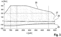
- the 3 shows the operating range of the internal combustion engine 1 in which the method according to the invention is carried out. Shown is an operating map in which the course of the internal combustion engine 1 generated or absorbed torque (m) is shown over the operating speed (n).
- the curve 26 shows the course of the maximum torque that can be generated by the internal combustion engine 1 .
- the (constant) curve 27, shows the limit line related to the torque with regard to the gradient of the temperature of the exhaust gas aftertreatment device 13. When the internal combustion engine 1 is operated at operating points above this curve 27, there is a positive temperature gradient, so that during the warm-up phase there is an increase the temperature of the exhaust gas aftertreatment device 13 is caused by the exhaust gas generated by the internal combustion engine 1.
- the (constant) curve 28 in the 3 also shows the braking torque caused by the internal combustion engine 1 during the unfired overrun mode and curve 29 shows the course of a maximum recuperation torque that can be effected by means of the internal combustion engine, which results from the braking torque of the internal combustion engine 1 in an unfired overrun mode and the resistance torque that can also be effected by means of the generator 24 composed.
- the area of the operating map below the curve 28 is that in which the electrical energy required for operating the heating device(s) 23 can advantageously be generated by means of the generator 24 .
- One purpose of the method according to the invention is to use the heating device(s) 23 to heat the exhaust gas emitted by the internal combustion engine 1 during overrun operation and to route it via the exhaust gas recirculation line 19 in order to recirculate this line as quickly as possible after a cold start of the internal combustion engine until a sufficiently high to heat temperature.
- the exhaust gas cooler 21 integrated into the exhaust gas recirculation line 19 can counteract this purpose if it simultaneously brings about a cooling effect due to a transfer of thermal energy from the exhaust gas to the coolant of the cooling system 22 . According to the invention, therefore, the exhaust gas cooler 21 is partially or completely deactivated during this measure by the internal combustion engine according to the 1 a mass flow of coolant of the cooling system conducted through the exhaust gas cooler 21 is reduced (possibly down to zero).
- the exhaust gas to be routed via the exhaust gas recirculation line 19 is partially or completely routed via an exhaust gas bypass 30 bypassing the exhaust gas cooler 21, if one is provided, as is the case with the internal combustion engine according to FIG 2 the case is.
- the exhaust gas cooler 21 can then no Bring about cooling of the exhaust gas guided through the exhaust gas bypass 30 .
- this can have the disadvantage that the heated exhaust gas does not heat up the exhaust gas cooler 21 itself, or heats it up only to a reduced extent.
- the engine according to 2 the one according to the 1 .
- the respective exhaust gas treatment device 13 of the internal combustion engine according to 1 and 2 may concretely have a configuration that will be described below.
- At least one heating device 23 should preferably be arranged upstream of the particle filter 18 in the exhaust line 8 .
- This can also be arranged directly upstream of the particle filter 18 or directly upstream of the SCR catalytic converter 16 (which can, for example, be configured as an SCR disk), with the SCR catalytic converter 16 in turn being able to be arranged directly upstream of the particle filter 18.
- the particle filter 18 can preferably be designed in such a way that regeneration by burning off soot already takes place at temperatures >350.degree.
- the cellularity of the SCR catalytic converter 16 can preferably be maximized compared to that of the particle filter 18 in order to maximize the surface area effective for NOx conversion.
- the SCR catalytic converter 16 Due to the nitrogen oxide storage catalytic converter 15, which is arranged upstream of the SCR catalytic converter 16, the SCR catalytic converter 16 can be made passive. However, an active version using a dosing and mixing section between the injection device 17 and the SCR catalytic converter 16 is also possible.
- the start of conversion for HC, CO, NOx and particle emissions can be reached relatively quickly after a cold start of the internal combustion engine.
- the in the 1 and 2 The exhaust gas aftertreatment devices 13 shown are also advantageous with regard to an on-board diagnosis (OBD) of the internal combustion engine, since two different exhaust gas aftertreatment components are used for the conversion of the HC and CO emissions. Two exhaust gas aftertreatment components are also available for the NOx conversion, and in the illustrated use of the nitrogen oxide storage catalytic converter 15 there are even three. This ensures compliance with the respective emission thresholds in the event of a fault in an exhaust aftertreatment component.
- OBD on-board diagnosis
Landscapes
- Engineering & Computer Science (AREA)
- Chemical & Material Sciences (AREA)
- Combustion & Propulsion (AREA)
- Mechanical Engineering (AREA)
- General Engineering & Computer Science (AREA)
- Chemical Kinetics & Catalysis (AREA)
- Health & Medical Sciences (AREA)
- Toxicology (AREA)
- Exhaust-Gas Circulating Devices (AREA)
Abstract
Description
- Die Erfindung betrifft ein Verfahren zum Betreiben einer Brennkraftmaschine, die einen Verbrennungsmotor, einen mit dem Verbrennungsmotor gekoppelten Generator, einen Frischgasstrang, einen Abgasstrang, eine Abgasrückführleitung, die aus dem Abgasstrang abzweigt und in den Frischgasstrang mündet, und mindestens eine elektrische Heizvorrichtung, die in den Abgasstrang oder in die Abgasrückführleitung integriert ist, umfasst.
- Im Betrieb einer Brennkraftmaschine kann eine Abgasrückführung vorgesehen sein, um die Schadstoffrohemissionen des Verbrennungsmotors der Brennkraftmaschine, insbesondere hinsichtlich der Stickoxidemissionen, möglichst gering zu halten. Dabei wird Abgas aus einem Abgasstrang der Brennkraftmaschine abgezweigt und in einen Frischgasstrang der Brennkraftmaschine eingeleitet und dort mit Luft vermischt. Dieses Luft-Abgas-Gemisch wird dann dem Verbrennungsmotor als Frischgas für eine Verbrennung mit Kraftstoff zugeführt. Bekannt sind dabei sowohl Hochdruck- als auch Niederdruckabgasrückführungen, wobei im Fall einer Niederdruckabgasrückführung das Abgas stromab einer Abgasturbine eines Abgasturboladers aus dem Abgasstrang abgezweigt und stromauf eines Frischgasverdichters des Abgasturboladers in den Abgasstrang eingeleitet wird. Bei einer Hochdruckabgasrückführung erfolgt die Abzweigung dagegen, sofern ein Abgasturbolader vorgesehen ist, stromauf der Abgasturbine und die Einleitung stromab des Frischgasverdichters. Für eine Steuerung der Menge des rückgeführten Abgases ist in eine für die Überleitung von Abgas von dem Abgasstrang zu dem Frischgasstrang vorgesehene Abgasrückführleitung ein sogenanntes AGR-Ventil integriert. Weiterhin ist in eine solche Abgasrückführleitung üblicherweise auch noch ein Abgaskühler zur bedarfsweisen Kühlung des über die Abgasrückführleitung geführten Abgases vorgesehen. Dadurch sollen negative Auswirkungen einer zu hohen Temperatur des Frischgases auf die Verbrennungsvorgänge in dem Verbrennungsmotor sowie im Fall einer Niederdruckabgasrückführung eine thermische Überlastung des Frischgasverdichters vermieden werden.
- Eine Kühlung von Abgas mittels eines Abgaskühlers kann entweder direkt oder indirekt durch Umgebungsluft erfolgen, wobei bei einer indirekten Kühlung in dem Abgaskühler ein Übergang von Wärmeenergie von dem Abgas auf ein flüssiges Kühlmittel erfolgt, das dann in einem Kühlmittelkühler wieder rückgekühlt wird. Der Vorteil eines solchen indirekt kühlenden Abgaskühlers liegt in der Realisierung einer relativ hohen Kühlleistung bei relativ kleinem Bauraum.
- Nach einem Kaltstart einer Brennkraftmaschine, d.h. nach einer Inbetriebnahme bei relativ geringer und insbesondere im Wesentlichen der Umgebungstemperatur entsprechender Temperatur der Brennkraftmaschine beziehungsweise der dazugehörigen Komponenten kann eine Abgasrückführung üblicherweise nicht unmittelbar umgesetzt werden, weil es aufgrund des dann noch relativ kalten Abgases, das von dem Verbrennungsmotor erzeugt wurde, in einem erheblichen Ausmaß zu einer Kondensation von Feuchtigkeit in der Abgasrückführleitung kommen kann. Dieses Kondensat kann zu einer Beschädigung von in die Abgasrückführleitung und/oder in den Frischgasstrang integrierten Komponenten führen.
- Um die Schadstoff- und insbesondere Stickoxidrohemissionen einer Brennkraftmaschine nach einem Kaltstart möglichst gering zu halten, wäre eine möglichst schnelle Aktivierung einer Abgasrückführung vorteilhaft.
- Die
AT 520 414 A1 - Die
DE 10 2012 209 202 A1 beschreibt ein Verfahren zum Betreiben eines Hybrid- oder Elektrofahrzeugs, wobei elektrische Energie, die infolge eines Betätigens eines regenerativen Bremssystems erzeugt wurde, direkt, d.h. unter Umgehung einer Batterie, zu einem elektrischen Nebenaggregat des Hybrid- oder Elektrofahrzeugs geführt wird. Das elektrische Nebenaggregat kann ein elektrisch beheizter Katalysator sein. - Die
AT 521 758 A1 - Die
EP 2 336 538 A1 beschreibt eine Brennkraftmaschine mit einer Abgasrückführleitung, in die ein Abgaskühler integriert ist. Stromab des Abgaskühlers ist in der Abgasrückführleitung eine steuerbare Verzweigung vorgesehen, mittels der das von dem Abgaskühler kommende Abgas zum einen weiter über die Abgasrückführleitung und damit in einen Frischgasstrang der Brennkraftmaschine und zum anderen zurück in den Abgasstrang führbar ist. Dadurch wird ermöglicht, bedarfsweise das gesamte Abgas der Brennkraftmaschine über den Abgaskühler zu führen, auch wenn nur ein Teil davon für eine Abgasrückführung genutzt werden soll. Insbesondere nach einem Kaltstart der Brennkraftmaschine kann dadurch Wärmeenergie des Abgases möglichst vollständig auf ein den Abgaskühler durchströmendes Kühlmittel übertragen werden, um dieses vorzuwärmen. - Der Erfindung lag die Aufgabe zugrunde, eine Möglichkeit aufzuzeigen, eine Abgasrückführung möglichst schnell nach einem Kaltstart einer Brennkraftmaschine aktivieren zu können.
- Diese Aufgabe wird durch die Umsetzung eines Verfahrens gemäß dem Patentanspruch 1 gelöst. Vorteilhafte Ausführungsformen dieses Verfahrens sind Gegenstände der weiteren Patentansprüche und ergeben sich aus der nachfolgenden Beschreibung der Erfindung.
- Ein erfindungsgemäßes Verfahren zum Betreiben einer Brennkraftmaschine, die einen Verbrennungsmotor, einen mit dem Verbrennungsmotor gekoppelten Generator, einen Frischgasstrang, einen Abgasstrang, eine Abgasrückführleitung, die aus dem Abgasstrang abzweigt und in den Frischgasstrang mündet, und mindestens eine elektrische Heizvorrichtung, die in den Abgasstrang oder in die Abgasrückführleitung integriert ist, umfasst, ist dadurch gekennzeichnet, dass während eines Schubbetriebs des Verbrennungsmotors, in dem dieser eine negative Antriebsleistung beziehungsweise eine Bremsleistung bereitstellt, wobei dazu vorzugsweise kein Kraftstoff in die Brennräume eingebacht wird, die Heizvorrichtung mit von dem Generator bereitgestellter Energie betrieben und mittels der Heizvorrichtung erwärmtes Abgas (das aufgrund des Schubbetriebs im Wesentlichen oder ausschließlich aus Luft bestehen kann) teilweise oder vollständig über die Abgasrückführleitung geführt wird.
- Der Schubbetrieb kann dabei insbesondere daraus resultieren, dass ein sich bewegendes Kraftfahrzeug, für dessen Antrieb die Brennkraftmaschine grundsätzlich vorgesehen ist, unter Nutzung seiner kinetischen Energie den Verbrennungsmotor antreibt, indem der zwischen dem Verbrennungsmotor und den angetriebenen Rädern des Kraftfahrzeugs liegende Abschnitt des Antriebsstrangs des Kraftfahrzeugs nicht unterbrochen bzw. eingekuppelt ist. Der insbesondere unbefeuerte Verbrennungsmotor wird dann durch das sich bewegende Kraftfahrzeug mitgeschleppt, wobei dieser und die mit diesem gekoppelten Komponenten, insbesondere der Generator, die negative Antriebsleistung beziehungsweise die Bremsleistung erzeugt. Ein Schubbetrieb einer Brennkraftmaschine liegt üblicherweise dann vor, wenn das Kraftfahrzeug verlangsamt werden soll, wie insbesondere bei einem Ausrollen vor einem erwarteten Halt, beispielsweise an einer Verkehrsampel, oder wenn das Kraftfahrzeug ein Gefälle hinunterfährt und dabei nicht beschleunigt werden soll. Üblicherweise geht ein solcher Schubbetrieb einer Brennkraftmaschine daher zumindest zeitweise mit einem Bremsbetrieb des Kraftfahrzeugs, in dem dieses durch eine Nutzung einer Betriebsbremse abgebremst wird, einher. Während eines Schubbetriebs einer Brennkraftmaschine wird daher häufig bewusst kinetische Energie des Kraftfahrzeugs reduziert, wobei der reduzierte Anteil der Energie üblicherweise ungenutzt verloren geht.
- Durch das erfindungsgemäße Vorgehen kann die Reduzierung von kinetischer Energie des Kraftfahrzeugs oder eines sonstigen, den Verbrennungsmotor mitschleppenden Systems vorteilhaft genutzt werden, um die Heizvorrichtung zu betreiben. Dies weist zum einen den Vorteil auf, dass die für den Betrieb der Heizvorrichtung erforderliche elektrische Energie nicht durch eine Umwandlung von Kraftstoff mittels eines Lastbetriebs des Verbrennungsmotors, in dem dieser eine positive Antriebsleistung bereitstellt, erzeugt werden muss. Zum anderen wird das Abgas, das insbesondere bei einem unbefeuerten Schubbetrieb des Verbrennungsmotors eine üblicherweise nur sehr niedrige Abgastemperatur aufweist, mittels der Heizvorrichtung beheizt, so dass trotz des Schubbetriebs der Brennkraftmaschine der Abgasstrang (bis zu dem Abzweig der Abgasrückführleitung) und die Abgasrückführleitung aktiv beheizt wird. Ein konventioneller Schubbetrieb würde dagegen aufgrund der sehr geringen Abgastemperatur tendenziell eher ein Auskühlen des Abgasstrangs und der Abgasrückführleitung bewirken.
- Die Durchführung eines erfindungsgemäßen Verfahrens kann insbesondere während einer Warmlaufphase der Brennkraftmaschine, die dann vorliegt, wenn zumindest eine Komponente der Brennkraftmaschine, beispielsweise der Verbrennungsmotor, eine Betriebstemperatur aufweist, die unterhalb einer definierten Mindesttemperatur liegt, von Vorteil sein, denn während einer solchen Warmlaufphase stellt sich die bereits beschriebene Problematik, wonach die Abgasrückführleitung und die darin integrierten Komponenten so kalt sein können, dass aufgrund einer Kondensationsgefahr keine Abgasrückführung durchgeführt beziehungsweise kein Abgas über die Abgasrückführleitung geführt werden kann. Eine solche Kondensationsgefahr besteht bei der Durchführung des erfindungsgemäßen Verfahrens aufgrund des Erhitzens des Abgases mittels der Heizvorrichtung im Wesentlichen nicht. Gleichzeitig bewirkt das Führen des erhitzten Abgases über die Abgasrückführleitung eine möglichst schnelle Erwärmung der Abgasrückführleitung mit den darin integrierten Komponenten, wodurch die Gefahr einer Kondensatbildung, die insbesondere an kalten Oberflächen vorliegt, reduziert wird. Dementsprechend kann es sinnvoll sein, die Heizvorrichtung während eines Schubbetriebs des Verbrennungsmotors zumindest auch oder nur während einer Warmlaufphase der Brennkraftmaschine durchzuführen. Durch das Erwärmen der Abgasrückführleitung kann eine Abgasrückführung möglichst schnell nach einem Kaltstart der Brennkraftmaschine durchgeführt werden.
- Eine Warmlaufphase kann insbesondere mit einem Kaltstart der Brennkraftmaschine beginnen. Eine solche kann jedoch auch dann auftreten, wenn der Verbrennungsmotor für einen längeren Zeitraum mit nur geringer Last oder sogar im Schubbetrieb betrieben wurde, beispielsweise aufgrund einer länger andauernden Gefällefahrt eines die Brennkraftmaschine umfassenden Kraftfahrzeugs.
- Die Heizvorrichtung kann vorzugsweise einer in den Abgasstrang integrierten Abgasnachbehandlungseinrichtung zugeordnet sein, wobei die Abgasrückführleitung stromab der Abgasnachbehandlungseinrichtung aus dem Abgasstrang abzweigt. Dadurch kann die Heizvorrichtung auch dazu genutzt werden, die Abgasnachbehandlungseinrichtung bedarfsweise zu erhitzen, was wiederum insbesondere während einer Warmlaufphase der Brennkraftmaschine von Vorteil sein kann, um nach einem Kaltstart möglichst schnell die Anspringtemperatur der Abgasnachbehandlungseinrichtung, ab der von einer ausreichenden Wirksamkeit für die Abgasnachbehandlung ausgegangen werden kann, zu erreichen. Zudem kann die Abgasnachbehandlungseinrichtung bei einem länger andauernden Betrieb des Verbrennungsmotors mit geringer Last oder im Schub mittels der Heizvorrichtung ausreichend warm gehalten werden. Auch kann ein Erhitzen der Abgasnachbehandlungseinrichtung dafür vorgesehen sein, temporär eine für eine Regeneration relativ hohe Temperatur zu erreichen. Durch eine solche Doppelnutzung einer Heizvorrichtung kann vermieden werden, eine separate Heizvorrichtung, die ausschließlich für ein Erwärmen der Abgasrückführleitung im Rahmen eines erfindungsgemäßen Verfahrens genutzt wird, bereitstellen zu müssen.
- In die Abgasrückführleitung kann vorzugsweise ein Abgaskühler beziehungsweise eine erste Wärmetauschseite davon integriert sein, um während eines Lastbetriebs des Verbrennungsmotors, insbesondere während eines Normalbetriebs der Brennkraftmaschine (d.h. nicht während eines Warmlaufbetriebs), das über die Abgasrückführleitung geführte Abgas zu kühlen. Dadurch kann eine thermische Überlastung von in die Abgasrückführleitung und in den sich ab der Mündung der Abgasrückführleitung erstreckenden Abschnitt des Frischgasstrangs, insbesondere eine thermische Überlastung eines in diesen Abschnitt des Frischgasstrangs integrierten Frischgasverdichters, vermieden werden. Dem erfindungsgemäß angestrebten Ziel einer Erwärmung der Abgasrückführleitung und der Einleitung noch relativ warmen Abgases in den Frischgasstrang während einer Warmlaufphase der Brennkraftmaschine kann ein solcher Abgaskühler jedoch entgegenwirken. Vorzugsweise ist im Rahmen eines erfindungsgemäßen Verfahrens daher vorgesehen, dass während des Schubbetriebs das über die Abgasrückführleitung zu führende Abgas über einen (den Abgaskühler umgehenden) Abgasbypass der Abgasrückführleitung geführt wird und/oder eine Kühlmittelströmung durch den Abgaskühler beziehungsweise durch eine zweite Wärmetauschseite davon im Vergleich zu einem (insbesondere jedem) Lastbetrieb reduziert oder (vollständig) verhindert wird. Dadurch kann folglich eine ungewollte Kühlung des über die Abgasrückführleitung geführten Abgases mittels des Abgaskühlers vermieden oder zumindest gering gehalten werden. Zur Reduzierung oder Verhinderung der Kühlmittelströmung durch den Abgaskühler kann diese grundsätzlich entsprechend gedrosselt werden. Vorteilhaft kann jedoch vorgesehen sein, die Kühlmittelströmung teilweise oder vollständig über einen (den Abgaskühler umgehenden) Kühlmittelbypass eines Kühlsystems der Brennkraftmaschine zu führen. Dadurch kann vermieden werden, dass durch eine Reduzierung oder Verhinderung der Kühlmittelströmung durch den Abgaskühler auch eine Kühlleistung für andere Komponenten des Kühlsystems, die in einen oder mehrere auch den Abgaskühler umfassende Kühlkreise integriert sind, verringert wird.
- Um die kinetische Energie, die im Rahmen eines erfindungsgemäßen Verfahrens aufgrund des Schubbetriebs des Verbrennungsmotors durch Umwandlung mittels des Generators für den Betrieb der Heizvorrichtung nutzbar ist, in einem möglichst großen Ausmaß zu verwenden, kann vorzugsweise vorgesehen sein, dass während des Schubbetriebs der Generator mit maximaler elektrischer Leistung betrieben beziehungsweise belastet wird.
- Im Rahmen eines erfindungsgemäßen Verfahrens kann es gegebenenfalls sinnvoll sein, die Heizvorrichtung zusätzlich mit Energie zu betreiben, die aus einer Energiespeicherquelle, beispielsweise einer Batterie, stammt. Dabei kann insbesondere vorgesehen sein, dass die Heizvorrichtung nur dann zusätzlich mit Energie aus der Energiespeicherquelle betrieben wird, wenn eine Soll-Heizleitung der Heizvorrichtung größer als eine elektrische Ist-Leistung des Generators ist. Mit anderen Worten kann vorgesehen sein, dass die Energiespeicherquelle nur dann für einen Betrieb der Heizvorrichtung genutzt wird, wenn der Schubbetrieb der Brennkraftmaschine so schwach ist, dass die mittels des Generators erzeugbare elektrische Leistung geringer als die für ein Heizen des Abgases mittels der Heizvorrichtung vorgesehene Heizleistung ist.
- Der Abzweig der Abgasrückführleitung und/oder, sofern vorgesehen, die Abgasnachbehandlungseinrichtung kann/können stromab einer in den Abgasstrang integrierten Abgasturbine (eines Abgasturboladers) angeordnet sein, weil sich bei einer solchen Ausgestaltung einer Brennkraftmaschine im besonderen Maße die Problematik einer nur relativ langsamen Erwärmung der Abgasrückführleitung und/oder der Abgasnachbehandlungseinrichtung stellt, weil stromab der Abgasturbine relativ kaltes Abgas vorliegt. Dies ist nicht nur in einem bereits erfolgten Übergang von Wärmeenergie auf die Abgasturbine sondern insbesondere auch in der funktionsgemäßen Entspannung des Abgases durch die Abgasturbine begründet.
- Die Abgasnachbehandlungseinrichtung einer erfindungsgemäß betriebenen Brennkraftmaschine kann insbesondere einen oder mehrere der folgenden Abgasnachbehandlungskomponenten umfassen: Oxidationskatalysator, Stickoxidspeicherkatalysator, SCR-Katalysator (SCR: Selektive katalytische Reduktion von Stickoxiden), Partikelfilter.
- Weiterhin bevorzugt kann vorgesehen sein, dass der Verbrennungsmotor im Rahmen eines erfindungsgemäßen Verfahrens selbstzündend und vorzugsweise auch quantitätsgeregelt betrieben wird. Der Verbrennungsmotor kann demnach insbesondere in Form eines Dieselmotors ausgestaltet sein, weil ein solcher Dieselmotor grundsätzlich relativ kaltes Abgas erzeugt und folglich insbesondere nach einem Kaltstart eines solchen Dieselmotors nur relativ langsam eine ausreichende Erwärmung des Abgasstrangs sowie einer Abgasrückführleitung erreicht wird. Zudem können die Schadstoffemissionen insbesondere eines Dieselmotors vorteilhaft mittels eine Abgasrückführung beeinflusst werden. Möglich ist aber auch, dass der Verbrennungsmotor im Rahmen eines erfindungsgemäßen Verfahrens fremdgezündet und insbesondere auch quantitätsgeregelt betrieben wird und demnach als Ottomotor ausgestaltet ist. Möglich ist zudem eine Kombination aus selbstzündendem und fremdgezündetem Betrieb, beispielsweise bei einer Ausgestaltung als Verbrennungsmotor mit homogener Kompressionszündung. Der Verbrennungsmotor kann im Rahmen eines erfindungsgemäßen Verfahrens mit Flüssigkraftstoff (d.h. Diesel oder Benzin) oder mit einem gasförmigen Kraftstoff (insbesondere Erdgas, LNG oder LPG) betrieben werden.
- In die Abgasrückführleitung kann vorzugsweise eine Abzweigung zur Ausgestaltung einer Brennkraftmaschine, wie sie in der
EP 2 336 538 A1 beschrieben ist, integriert sein. - Die Erfindung betrifft im Übrigen auch ein Verfahren zum Betreiben eines Kraftfahrzeugs in der zuvor beschriebenen Art und Weise. Das Kraftfahrzeug kann insbesondere ein radbasiertes und nicht schienengebundenes Kraftfahrzeug (vorzugsweise ein PKW oder ein LKW) sein.
- Die Erfindung wird nachfolgend anhand von in den Zeichnungen dargestellten Ausführungsbeispielen näher erläutert. In den Zeichnungen zeigt, jeweils in vereinfachter Darstellung:
- Fig. 1:
- eine für die Durchführung eines erfindungsgemäßen Verfahrens geeignete Brennkraftmaschine gemäß einer ersten Ausgestaltungsform;
- Fig. 2:
- eine für die Durchführung eines erfindungsgemäßen Verfahrens geeignete Brennkraftmaschine gemäß einer zweiten Ausgestaltungsform; und
- Fig. 3:
- ein Betriebskennfeld einer erfindungsgemäß betriebenen Brennkraftmaschine.
- Die in der
Fig. 1 gezeigte Brennkraftmaschine umfasst einen Verbrennungsmotor 1, der beispielhaft in Form eines Hubkolbenmotors mit vier in Reihe angeordneten Zylinderöffnungen 2 ausgestaltet ist. Die Zylinderöffnungen 2 begrenzen mit darin geführten Hubkolben 3 und einem Zylinderkopf jeweils einen Brennraum 4. Diesen Brennräumen 4 wird im Betrieb des Verbrennungsmotors 1 und damit der Brennkraftmaschine Frischgas über einen Frischgasstrang 5 zugeführt, wobei die Zufuhr des Frischgases mittels Einlassventilen 6, die den einzelnen Brennräumen 4 zugeordnet sind, gesteuert wird. Bei dem Frischgas handelt es sich ausschließlich oder hauptsächlich um Luft, die aus der Umgebung angesaugt wird. Bei der Verbrennung von Gemischmengen, die aus dem Frischgas sowie aus direkt über Kraftstoffinjektoren 7 in die Brennräume 4 eingespritztem Kraftstoff bestehen, wird Abgas erzeugt. Dieses Abgas wird über einen Abgasstrang 8 der Brennkraftmaschine abgeführt, wobei das Ausbringen des Abgases aus den einzelnen Brennräumen 4 mittels Auslassventilen 9 gesteuert wird. - Die Brennkraftmaschine ist aufgeladen ausgestaltet, wozu in den Frischgasstrang 5 ein Frischgasverdichter 10 integriert ist. Der Frischgasverdichter 10 ist Teil eines Abgasturboladers, der weiterhin noch eine Abgasturbine 11 umfasst, die in den Abgasstrang 8 integriert ist. Abgas, das die Abgasturbine 11 durchströmt, führt zu einem rotierenden Antrieb eines Turbinenlaufrads, das über eine Welle 12 drehantreibend mit einem Verdichterlaufrad des Frischgasverdichters 10 verbunden ist, so dass im Ergebnis ein Antrieb des Frischgasverdichters 10 mittels der Abgasturbine 11 erfolgt.
- Die Abgasturbine 11 ist stromauf (bezüglich der Strömungsrichtung des Abgases) einer Abgasnachbehandlungseinrichtung 13 in dem Abgasstrang 8 angeordnet. Die Abgasnachbehandlungseinrichtung 13 ist dafür vorgesehen, Bestandteile des Abgases, die Schadstoffe darstellen, aus dem Abgas zu entfernen oder in unschädliche Bestandteile umzuwandeln.
- Die Abgasnachbehandlungseinrichtung 13 umfasst in dem Ausgestaltungsbeispiel gemäß der
Fig. 1 mehrere Abgasnachbehandlungskomponenten: konkret ist ein Oxidationskatalysator 14, ein Stickoxidspeicherkatalysator 15, ein SCR-Katalysator 16 mit vorgelagerter Einspritzvorrichtung 17 für ein Reduktionsmittel (NH3) sowie ein Partikelfilter 18 vorgesehen. Dabei sind der Oxidationskatalysator 14 sowie der Stickoxidspeicherkatalysator 15 integral, d.h. in Form einer beide Abgasnachbehandlungsfunktionen bewirkenden, ersten Abgasnachbehandlungskomponente ausgestaltet. Das gleiche gilt für den SCR-Katalysator 16 und den Partikelfilter 18 in Form einer integralen, zweiten Abgasnachbehandlungskomponente. - Die Brennkraftmaschine umfasst weiterhin eine Abgasrückführleitung 19, die stromab der Abgasnachbehandlungseinrichtung 13 aus dem Abgasstrang 8 abzweigt und die stromauf des Frischgasverdichters 10 in den Frischgasstrang 5 mündet. Mittels der Abgasrückführleitung 19 kann bedarfsweise ein Teil oder auch das gesamte an der Mündung von dieser ankommende Abgas in den Frischgasstrang 5 eingeleitet werden, wo dieses mit Luft vermischt und nach einer Verdichtung mittels des Frischgasverdichters 10 den Brennräumen 4 des Verbrennungsmotors 1 (wieder) zugeführt wird. Eine Steuerung beziehungsweise Einstellung des Anteils (0% bis 100%) des über die Abgasrückführleitung 19 zu führenden Abgases kann mittels zwei Steuerventilen 20 realisiert werden, von denen eines in die Abgasrückführleitung 19 integriert ist (sogenanntes "Abgasrückführventil") und das andere stromab der Abzweigung der Abgasrückführleitung 19 in den Abgasstrang 8 integriert ist (sogenannte "Abgasklappe").
- In die Abgasrückführleitung 19 ist weiterhin ein Abgaskühler 21 beziehungsweise eine erste Wärmetauschseite davon integriert. Eine zweite Wärmetauschseite des Abgaskühlers 21 ist in ein Kühlsystem 22 der Brennkraftmaschine integriert, in dem ein flüssiges Kühlmittel in mehreren Kühlkreisen förderbar ist, um eine Kühlung von denjenigen Komponenten der Brennkraftmaschine, für die eine solche Kühlung erforderlich ist, zu bewirken.
- In den Abgasstrang 8 (beziehungsweise in den Abschnitt davon, der stromauf der Abzweigung der Abgasrückführleitung 19 gelegen ist) und/oder in die Abgasrückführleitung 19 sind eine oder mehrere elektrische Heizvorrichtungen 23 integriert. Die
Fig. 1 zeigt eine Vielzahl von Möglichkeiten bezüglich der Anordnung dieser Heizvorrichtung(en) 23. Der oder die in den Abgasstrang 8 integrierten Heizvorrichtungen 23, sofern vorhanden, sind vorzugsweise zumindest einer der (kombinierten) Abgasnachbehandlungskomponenten zugeordnet, so dass die entsprechende(n) Abgasnachbehandlungskomponenten(n) bedarfsweise mittels der Heizvorrichtung(en) 23 beheizbar ist/sind. Eine Übertragung der Wärmeenergie kann dabei mittels Strahlung und/oder Konvektion erfolgen. Die der oder den Abgasnachbehandlungskomponenten zugeordnete(n) Heizvorrichtung(en) 23 kann/können gemäß derFig. 1 beispielsweise unmittelbar stromauf davon angeordnet oder in diese integriert sein. Eine Anordnung von Heizvorrichtungen 23 unmittelbar stromab der Abgasnachbehandlungskomponenten ist gemäß derFig. 1 ebenfalls möglich. Bei einer Integration einer oder mehrerer Heizvorrichtungen 23 in der Abgasrückführleitung 19 können diese gemäß derFig. 1 beispielsweise unmittelbar stromauf und/oder unmittelbar stromab des Abgaskühlers 21 angeordnet sein. - Die für einen Betrieb der Heizvorrichtung(en) 23 erforderliche Energie kann einerseits mittels eines Generators 24 bereitgestellt werden, der direkt von dem Verbrennungsmotor 1 beziehungsweise von einer Abtriebswelle (Kurbelwelle) 13 des Verbrennungsmotors 1 angetrieben wird. Ergänzend oder alternativ kann die für einen Betrieb der Heizvorrichtung(en) 23 erforderliche Energie auch mittels einer Energiespeicherquelle 25 in Form einer Batterie bereitgestellt werden.
- Im Rahmen eines erfindungsgemäßen Verfahrens zum Betreiben einer Brennkraftmaschine gemäß der
Fig. 1 ist vorgesehen, die Heizvorrichtung(en) 23 (auch) dazu zu nutzen, während eines Schubbetriebs des Verbrennungsmotors 1 das von diesem ausgestoßene Abgas zu erwärmen, wobei dieses erwärmte Abgas teilweise oder vollständig über die Abgasrückführleitung 19 geführt wird, um diese zu erwärmen. Dies erfolgt insbesondere während einer Warmlaufphase nach einem Kaltstart der Brennkraftmaschine, um die Abgasrückführleitung 19 und die darin integrierten Komponenten sowie den in den Frischgasstrang 5 integrierten Frischgasverdichter 14 soweit zu erwärmen, dass die Gefahr einer Kondensation von Feuchtigkeit aus über die Abgasrückführleitung 19 geführtem Abgas auch dann nicht mehr besteht, wenn das Abgas nicht mehr mittels der Heizvorrichtung(en) 23 erwärmt wird. Dadurch soll insbesondere möglichst schnell nach einem Kaltstart der Brennkraftmaschine eine Abgasrückführung während eines Lastbetriebs des Verbrennungsmotors realisiert werden, was sich vorteilhaft hinsichtlich der Schadstoff- und insbesondere Stickoxidrohemissionen des Verbrennungsmotors 1 auswirkt. - Die
Fig. 3 zeigt den Betriebsbereich des Verbrennungsmotors 1, in dem das erfindungsgemäße Verfahren durchgeführt wird. Dargestellt ist ein Betriebskennfeld, in dem der Verlauf des von dem Verbrennungsmotor 1 erzeugten oder aufgenommenen Drehmoments (m) über der Betriebsdrehzahl (n) dargestellt ist. Die Kurve 26 zeigt dabei den Verlauf des von dem Verbrennungsmotor 1 maximal erzeugbaren Drehmoments. Die (konstant verlaufende) Kurve 27 zeigt dagegen die auf das Drehmoment bezogene Grenzlinie bezüglich des Gradienten der Temperatur der Abgasnachbehandlungseinrichtung 13. Bei einem Betrieb des Verbrennungsmotors 1 in oberhalb dieser Kurve 27 liegenden Betriebspunkten ist ein positiver Temperaturgradient gegeben, so dass während der Warmlaufphase eine Erhöhung der Temperatur der Abgasnachbehandlungseinrichtung 13 durch das von dem Verbrennungsmotor 1 erzeugte Abgas bewirkt wird. Bei einem Betrieb des Verbrennungsmotors 1 unterhalb dieser Kurve 27 liegt dagegen ein negativer Temperaturgradient vor, so dass während der Warmlaufphase üblicherweise eine Auskühlung der Abgasnachbehandlungseinrichtung 13 erfolgen würde. Die (konstant verlaufende) Kurve 28 in derFig. 3 zeigt weiterhin noch das von dem Verbrennungsmotor 1 während des unbefeuerten Schubbetriebs bewirkte Bremsmoment und die Kurve 29 den Verlauf eines mittels der Brennkraftmaschine maximal bewirkbaren Rekuperationsmoments, das sich aus dem Bremsmoment des in einem unbefeuerten Schubbetrieb befindlichen Verbrennungsmotors 1 sowie dem mittels des Generators 24 zusätzlich bewirkbaren Widerstandsmoments zusammensetzt. Der Bereich des Betriebskennfelds unterhalb der Kurve 28 ist derjenige, in dem mittels des Generators 24 in vorteilhafter Weise die für einen Betrieb der Heizvorrichtung(en) 23 benötigte elektrische Energie erzeugt werden kann. - Ein Zweck des erfindungsgemäßen Verfahrens besteht darin, mittels der Heizvorrichtung(en) 23 das während eines Schubbetriebs von dem Verbrennungsmotor 1 ausgestoßene Abgas zu erwärmen und über die Abgasrückführleitung 19 zu führen, um diese möglichst schnell nach einem Kaltstart der Brennkraftmaschine bis zum Erreichen einer ausreichend hohen Temperatur zu erwärmen. Diesem Zweck kann der in die Abgasrückführleitung 19 integrierte Abgaskühler 21 entgegenwirken, wenn dieser gleichzeitig eine Kühlwirkung aufgrund eines Übergangs von Wärmeenergie von dem Abgas auf das Kühlmittel des Kühlsystems 22 bewirkt. Erfindungsgemäß ist daher vorgesehen, den Abgaskühler 21 während dieser Maßnahme teilweise oder vollständig zu deaktivieren, indem bei der Brennkraftmaschine gemäß der
Fig. 1 ein Massenstrom von durch den Abgaskühler 21 geführtem Kühlmittel des Kühlsystems reduziert (gegebenenfalls bis auf null) wird. - Ergänzend oder alternativ dazu kann auch vorgesehen sein, das über die Abgasrückführleitung 19 zu führende Abgas teilweise oder vollständig über einen den Abgaskühler 21 umgehenden Abgasbypass 30 zu führen, sofern ein solcher vorgesehen ist, wie dies bei der Brennkraftmaschine gemäß der
Fig. 2 der Fall ist. Der Abgaskühler 21 kann dann keine Kühlung des über den Abgasbypass 30 geführten Abgases bewirken. Nachteilig daran kann jedoch sein, dass mittels des beheizten Abgases ein Erwärmen des Abgaskühlers 21 selbst nicht oder nur in einem reduzierten Umfang bewirkt wird. - Mit Ausnahme dieses zusätzlichen Abgasbypasses 30 sowie weiterer Steuerventile 20, die vorgesehen sind, um bedarfsgerecht Abgas über die Abgasrückführleitung 19 und/oder den Abgasbypasses 30 zu führen, entspricht die Brennkraftmaschine gemäß der
Fig. 2 derjenigen gemäß derFig. 1 . - Die jeweilige Abgasnachbehandlungseinrichtung 13 der Brennkraftmaschinen gemäß den
Fig. 1 und2 kann konkret eine Ausgestaltung aufweist, die nachfolgend beschrieben wird. - Zumindest eine Heizvorrichtung 23 sollte vorzugsweise stromauf des Partikelfilters 18 in dem Abgasstrang 8 angeordnet sein. Diese kann auch unmittelbar stromauf des Partikelfilters 18 oder unmittelbar stromauf des SCR-Katalysators 16 (de z.B. eine Ausgestaltung als SCR-Scheibe aufweisen kann) angeordnet sein, wobei der SCR-Katalysator 16 wiederum unmittelbar stromauf des Partikelfilters 18 angeordnet sein kann. Der Partikelfilter 18 kann vorzugsweise derart ausgeführt sein, dass eine Regeneration durch Rußabbrand bereits ab Temperaturen > 350°C erfolgt. Die Zelligkeit des SCR-Katalysators 16 kann vorzugsweise im Vergleich zu derjenigen des Partikelfilters 18 maximiert sein, um eine Maximierung der für die NOx-Konvertierung wirksamen Oberfläche zu realisieren. Durch den Stickoxidspeicherkatalysator 15, der stromauf des SCR-Katalysators 16 angeordnet ist, kann der SCR-Katalysator 16 passiv ausgeführt sein. Möglich ist aber auch eine aktive Ausführung unter Verwendung einer Dosier- und Mischstrecke zwischen der Einspritzvorrichtung 17 und dem SCR-Katalysator 16.
- Durch ein Beheizen der Abgasnachbehandlungseinrichtung 13 durch die mindestens eine Heizvorrichtung 13 kann nach einem Kaltstart der Brennkraftmaschine ein relativ schnelles Erreichen des Konvertierungsbeginns für HC-, CO-, NOx- und Partikelemissionen realisiert werden.
- Die in den
Fig. 1 und2 dargestellten Abgasnachbehandlungseinrichtungen 13 sind zudem vorteilhaft hinsichtlich einer On-Board-Diagnose (OBD) der Brennkraftmaschine, da für die Konvertierung der HC- und CO-Emissionen zwei unterschiedliche Abgasnachbehandlungskomponenten verwendet werden. Für die NOx-Konvertierung stehen ebenfalls zwei, bei der gezeigten Verwendung des Stickoxidspeicherkatalysators 15 sogar drei Abgasnachbehandlungskomponenten zur Verfügung. So wird im Fehlerfall einer Abgasnachbehandlungskomponente das Einhalten der jeweiligen Emissionsschwellen sichergestellt. -
- 1
- Verbrennungsmotor
- 2
- Zylinderöffnung
- 3
- Hubkolben
- 4
- Brennraum
- 5
- Frischgasstrang
- 6
- Einlassventil
- 7
- Kraftstoffinjektor
- 8
- Abgasstrang
- 9
- Auslassventil
- 10
- Frischgasverdichter
- 11
- Abgasturbine
- 12
- Welle
- 13
- Abgasnachbehandlungseinrichtung
- 14
- Oxidationskatalysator
- 15
- Stickoxidspeicherkatalysator
- 16
- SCR-Katalysator
- 17
- Einspritzvorrichtung
- 18
- Partikelfilter
- 19
- Abgasrückführleitung
- 20
- Steuerventil
- 21
- Abgaskühler
- 22
- Kühlsystem
- 23
- Heizvorrichtung
- 24
- Generator
- 25
- Energiespeicherquelle
- 26
- Verlauf des von dem Verbrennungsmotor maximal erzeugbaren Drehmoments
- 27
- auf das Drehmoment bezogene Grenzlinie bezüglich des Gradienten der Temperatur der Abgasnachbehandlungseinrichtung
- 28
- Verlauf des von dem Verbrennungsmotor während des unbefeuerten Schubbetriebs bewirkten Bremsmoments
- 29
- Verlauf eines mittels der Brennkraftmaschine maximal bewirkbaren Rekuperationsmoments
- 30
- Abgasbypass
Claims (10)
- Verfahren zum Betreiben einer Brennkraftmaschine, die einen Verbrennungsmotor (1), einen mit dem Verbrennungsmotor (1) gekoppelten Generator (24), einen Frischgasstrang (5), einen Abgasstrang (8), eine Abgasrückführleitung (19), die aus dem Abgasstrang (8) abzweigt und in den Frischgasstrang (5) mündet, und mindestens eine elektrische Heizvorrichtung (23), die in den Abgasstrang (8) oder in die Abgasrückführleitung (19) integriert ist, umfasst, dadurch gekennzeichnet, dass während eines Schubbetriebs des Verbrennungsmotors (1) die Heizvorrichtung (23) mit von dem Generator (24) bereitgestellter Energie betrieben und mittels der Heizvorrichtung (23) erwärmtes Abgas teilweise oder vollständig über die Abgasrückführleitung (19) geführt wird.
- Verfahren gemäß Anspruch 1, gekennzeichnet durch die Durchführung während einer Warmlaufphase der Brennkraftmaschine.
- Verfahren gemäß Anspruch 1 oder 2, dadurch gekennzeichnet, dass die Heizvorrichtung (23) einer Abgasnachbehandlungseinrichtung (13) zugeordnet ist und die Abgasrückführleitung (19) stromab der Abgasnachbehandlungseinrichtung (13) aus dem Abgasstrang (8) abzweigt.
- Verfahren gemäß einem der vorhergehenden Ansprüche, dadurch gekennzeichnet, dass in die Abgasrückführleitung (19) ein Abgaskühler (21) integriert ist, wobei während des Schubbetriebs das über die Abgasrückführleitung (19) zu führende Abgas über einen den Abgaskühler (21) umgehenden Abgasbypass (30) geführt wird und/oder eine Kühlmittelströmung durch den Abgaskühler (21) im Vergleich zu einem Lastbetrieb des Verbrennungsmotors (1) reduziert oder verhindert wird.
- Verfahren gemäß Anspruch 4, dadurch gekennzeichnet, dass die Kühlmittelströmung teilweise oder vollständig über einen Kühlmittelbypass eines Kühlsystems (22) der Brennkraftmaschine geführt wird.
- Verfahren gemäß einem der vorhergehenden Ansprüche, dadurch gekennzeichnet, dass während des Schubbetriebs des Verbrennungsmotors (1) der Generator (24) mit maximaler elektrischer Leistung betrieben wird.
- Verfahren gemäß einem der vorhergehenden Ansprüche, dadurch gekennzeichnet, dass die Heizvorrichtung (23) zusätzlich mit Energie betrieben wird, die aus einer Energiespeicherquelle (25) stammt.
- Verfahren gemäß Anspruch 7, dadurch gekennzeichnet, dass die Heizvorrichtung (23) nur dann zusätzlich mit Energie aus der Energiespeicherquelle (25) betrieben wird, wenn eine Soll-Heizleitung der Heizvorrichtung (23) größer als eine elektrische Ist-Leistung des Generators (24) ist.
- Verfahren gemäß einem der vorhergehenden Ansprüche, dadurch gekennzeichnet, dass die Abgasnachbehandlungseinrichtung (13) und/oder ein Abzweig der Abgasrückführleitung (19) stromab einer in den Abgasstrang (8) integrierten Abgasturbine (11) angeordnet ist/sind.
- Verfahren gemäß einem der vorhergehenden Ansprüche, dadurch gekennzeichnet, dass der Verbrennungsmotor (1) selbstzündend betrieben wird.
Applications Claiming Priority (1)
| Application Number | Priority Date | Filing Date | Title |
|---|---|---|---|
| DE102021107008.2A DE102021107008A1 (de) | 2021-03-22 | 2021-03-22 | Erwärmung einer Abgasrückführleitung während eines Schubbetriebs eines Verbrennungsmotors |
Publications (2)
| Publication Number | Publication Date |
|---|---|
| EP4063638A1 true EP4063638A1 (de) | 2022-09-28 |
| EP4063638B1 EP4063638B1 (de) | 2025-01-22 |
Family
ID=80739004
Family Applications (1)
| Application Number | Title | Priority Date | Filing Date |
|---|---|---|---|
| EP22161793.9A Active EP4063638B1 (de) | 2021-03-22 | 2022-03-14 | Erwärmung einer abgasrückführleitung während eines schubbetriebs eines verbrennungsmotors |
Country Status (3)
| Country | Link |
|---|---|
| US (1) | US11549453B2 (de) |
| EP (1) | EP4063638B1 (de) |
| DE (1) | DE102021107008A1 (de) |
Families Citing this family (1)
| Publication number | Priority date | Publication date | Assignee | Title |
|---|---|---|---|---|
| JP2025132751A (ja) * | 2024-02-29 | 2025-09-10 | トヨタ自動車株式会社 | 車両 |
Citations (8)
| Publication number | Priority date | Publication date | Assignee | Title |
|---|---|---|---|---|
| EP2336538A1 (de) | 2009-12-17 | 2011-06-22 | Volkswagen Aktiengesellschaft | Einrichtung zur Abgasrückführung sowie Verfahren zur Erwärmung eines Kühlmediums einer Brennkraftmaschine und Verwendung der Einrichtung zur Abgasrückführung |
| DE102012209202A1 (de) | 2011-06-06 | 2012-12-06 | GM Global Technology Operations LLC (n.d. Ges. d. Staates Delaware) | Verfahren zum Verwenden eines regenerativen Bremssystems zum Beheizen eines Kraftfahrzeugkatalysators und zum Antreiben von anderen elektrischen Nebenaggregaten |
| DE112011104505T5 (de) * | 2010-12-22 | 2013-12-24 | Denso Corporation | Abgaswärmeaustauscheinrichtung |
| DE102016201185A1 (de) * | 2016-01-27 | 2017-07-27 | Ford Global Technologies, Llc | Brennkraftmaschine mit Abgasnachbehandlung und Verfahren zum Betreiben einer derartigen Brennkraftmaschine |
| AT520414A1 (de) | 2017-08-17 | 2019-03-15 | Avl List Gmbh | Anordnung einer Verbrennungskraftmaschine mit Abgasnachbehandlungsanlage und Vorheizvorrichtung |
| AT521758A1 (de) | 2018-10-05 | 2020-04-15 | Avl List Gmbh | Verfahren und Ottomotoranordnung mit einer verbesserten Abgasnachbehandlung durch eine Schubabschaltungsstrategie |
| DE102019135832A1 (de) * | 2019-02-19 | 2020-08-20 | Jaguar Land Rover Limited | Katalysatorvorwärmungssteuerungsvorrichtung und -verfahren |
| DE102019135831A1 (de) * | 2019-02-19 | 2020-08-20 | Jaguar Land Rover Limited | Katalysatorvorwärmungssteuerungsvorrichtung und -verfahren |
Family Cites Families (5)
| Publication number | Priority date | Publication date | Assignee | Title |
|---|---|---|---|---|
| JP5038992B2 (ja) | 2008-08-19 | 2012-10-03 | 富士重工業株式会社 | ディーゼルエンジンの排気ガス再循環装置 |
| DE102019203061B4 (de) * | 2019-03-06 | 2024-10-24 | Ford Global Technologies, Llc | Verfahren zum Regenerieren eines NOx-Speicherkatalysators einer Abgasnachbehandlungsvorrichtung |
| DE102019113736A1 (de) | 2019-05-23 | 2020-11-26 | Volkswagen Aktiengesellschaft | Brennkraftmaschine mit variabler Auslassventilbetätigung und mit elektrischer Heizvorrichtung im Abgasstrang |
| DE102019131829B3 (de) | 2019-11-25 | 2021-01-14 | Volkswagen Aktiengesellschaft | Verfahren zur Abgasnachbehandlung eines Verbrennungsmotors |
| FR3109802B1 (fr) * | 2020-04-30 | 2024-07-05 | Renault Sas | Chauffage de système de dépollution de moteur thermique comportant un e-turbo |
-
2021
- 2021-03-22 DE DE102021107008.2A patent/DE102021107008A1/de active Pending
-
2022
- 2022-03-14 EP EP22161793.9A patent/EP4063638B1/de active Active
- 2022-03-21 US US17/699,959 patent/US11549453B2/en active Active
Patent Citations (8)
| Publication number | Priority date | Publication date | Assignee | Title |
|---|---|---|---|---|
| EP2336538A1 (de) | 2009-12-17 | 2011-06-22 | Volkswagen Aktiengesellschaft | Einrichtung zur Abgasrückführung sowie Verfahren zur Erwärmung eines Kühlmediums einer Brennkraftmaschine und Verwendung der Einrichtung zur Abgasrückführung |
| DE112011104505T5 (de) * | 2010-12-22 | 2013-12-24 | Denso Corporation | Abgaswärmeaustauscheinrichtung |
| DE102012209202A1 (de) | 2011-06-06 | 2012-12-06 | GM Global Technology Operations LLC (n.d. Ges. d. Staates Delaware) | Verfahren zum Verwenden eines regenerativen Bremssystems zum Beheizen eines Kraftfahrzeugkatalysators und zum Antreiben von anderen elektrischen Nebenaggregaten |
| DE102016201185A1 (de) * | 2016-01-27 | 2017-07-27 | Ford Global Technologies, Llc | Brennkraftmaschine mit Abgasnachbehandlung und Verfahren zum Betreiben einer derartigen Brennkraftmaschine |
| AT520414A1 (de) | 2017-08-17 | 2019-03-15 | Avl List Gmbh | Anordnung einer Verbrennungskraftmaschine mit Abgasnachbehandlungsanlage und Vorheizvorrichtung |
| AT521758A1 (de) | 2018-10-05 | 2020-04-15 | Avl List Gmbh | Verfahren und Ottomotoranordnung mit einer verbesserten Abgasnachbehandlung durch eine Schubabschaltungsstrategie |
| DE102019135832A1 (de) * | 2019-02-19 | 2020-08-20 | Jaguar Land Rover Limited | Katalysatorvorwärmungssteuerungsvorrichtung und -verfahren |
| DE102019135831A1 (de) * | 2019-02-19 | 2020-08-20 | Jaguar Land Rover Limited | Katalysatorvorwärmungssteuerungsvorrichtung und -verfahren |
Also Published As
| Publication number | Publication date |
|---|---|
| US20220298991A1 (en) | 2022-09-22 |
| EP4063638B1 (de) | 2025-01-22 |
| DE102021107008A1 (de) | 2022-10-13 |
| US11549453B2 (en) | 2023-01-10 |
Similar Documents
| Publication | Publication Date | Title |
|---|---|---|
| DE102015015794A1 (de) | Verfahren zum Aufheizen einer Abgasnachbehandlungseinrichtung eines Kraftfahrzeugs, insbesondere eines Hybridfahrzeugs | |
| DE102013205590A1 (de) | Verbrennungsmotor und Verfahren zum Steuern der Drehzahl des Verbrennungsmotors | |
| EP4026994B1 (de) | Abgasnachbehandlungssystem sowie verfahren zur abgasnachbehandlung eines verbrennungsmotors | |
| DE102013205575B4 (de) | Abgasnachbehandlungssystem | |
| DE102020100539A1 (de) | Verfahren zum Betreiben eines Kraftfahrzeugs mit einem Diesel-Hybrid-Antrieb sowie Diesel-Hybrid-Antrieb | |
| DE102020100529A1 (de) | Verbrennungsmotor sowie Verfahren zum Aufheizen einer Abgasanlage eines solchen Verbrennungsmotors | |
| DE102018106679B4 (de) | Verfahren zum Betreiben einer Brennkraftmaschine, Brennkraftmaschine und Kraftfahrzeug | |
| DE102020103565B4 (de) | Verfahren zur Abgasnachbehandlung eines Verbrennungsmotors sowie Verbrennungsmotor | |
| DE102017103560A1 (de) | Verbrennungsmotor und Verfahren zur Regeneration eines Partikelfilters im Abgaskanal eines Verbrennungsmotors | |
| DE102019203061A1 (de) | Verfahren zum Regenerieren eines NOx-Speicherkatalysators einer Abgasnachbehandlungsvorrichtung | |
| DE102019131829B3 (de) | Verfahren zur Abgasnachbehandlung eines Verbrennungsmotors | |
| EP4063638B1 (de) | Erwärmung einer abgasrückführleitung während eines schubbetriebs eines verbrennungsmotors | |
| DE102018104275A1 (de) | Abgasnachbehandlungssystem sowie Verfahren zur Abgasnachbehandlung eines Verbrennungsmotors | |
| DE102021205170A1 (de) | Brennkraftmaschine mit einer stromab eines Frischgasverdichters abzweigenden Sekundärluftleitung | |
| DE102018130799B4 (de) | Verbrennungsmotor und Verfahren zum Betreiben eines Verbrennungsmotors | |
| DE102020213702A1 (de) | Brennkraftmaschine mit Heizvorrichtung im Abgasstrang | |
| EP4036386B1 (de) | Verbrennungskraftmaschine für ein kraftfahrzeug, insbesondere für einen kraftwagen, sowie kraftfahrzeug, insbesondere kraftwagen | |
| DE102019115155B4 (de) | Abgasnachbehandlungssystem sowie Verfahren zur Abgasnachbehandlung eines Verbrennungsmotors | |
| EP4102036A1 (de) | Verfahren zur aufheizung eines elektrisch beheizbaren katalysators im leerlauf | |
| DE102022101751A1 (de) | Ansaugluft-Heizsystem für einen Fahrzeugmotor | |
| DE102021107092A1 (de) | Brennkraftmaschine mit Abgasnachbehandlungskomponente, Heizvorrichtung und Gasfördervorrichtung | |
| DE102021117857A1 (de) | Verbrennungsmotor mit Abgasnachbehandlungssystem sowie Verfahren zur Abgasnachbehandlung eines Verbrennungsmotors | |
| DE102021102240A1 (de) | Abgasnachbehandlung bei einer Brennkraftmaschine | |
| DE102020117724A1 (de) | Abgasnachbehandlungssystem sowie Verfahren zur Abgasnachbehandlung eines Verbrennungsmotors | |
| EP4083399B1 (de) | Brennkraftmaschine mit elektrischer abgasturbine und abgasnachbehandlungseinrichtung stromauf der abgasturbine |
Legal Events
| Date | Code | Title | Description |
|---|---|---|---|
| PUAI | Public reference made under article 153(3) epc to a published international application that has entered the european phase |
Free format text: ORIGINAL CODE: 0009012 |
|
| STAA | Information on the status of an ep patent application or granted ep patent |
Free format text: STATUS: THE APPLICATION HAS BEEN PUBLISHED |
|
| AK | Designated contracting states |
Kind code of ref document: A1 Designated state(s): AL AT BE BG CH CY CZ DE DK EE ES FI FR GB GR HR HU IE IS IT LI LT LU LV MC MK MT NL NO PL PT RO RS SE SI SK SM TR |
|
| STAA | Information on the status of an ep patent application or granted ep patent |
Free format text: STATUS: REQUEST FOR EXAMINATION WAS MADE |
|
| 17P | Request for examination filed |
Effective date: 20230328 |
|
| RBV | Designated contracting states (corrected) |
Designated state(s): AL AT BE BG CH CY CZ DE DK EE ES FI FR GB GR HR HU IE IS IT LI LT LU LV MC MK MT NL NO PL PT RO RS SE SI SK SM TR |
|
| GRAP | Despatch of communication of intention to grant a patent |
Free format text: ORIGINAL CODE: EPIDOSNIGR1 |
|
| STAA | Information on the status of an ep patent application or granted ep patent |
Free format text: STATUS: GRANT OF PATENT IS INTENDED |
|
| INTG | Intention to grant announced |
Effective date: 20241112 |
|
| GRAS | Grant fee paid |
Free format text: ORIGINAL CODE: EPIDOSNIGR3 |
|
| GRAA | (expected) grant |
Free format text: ORIGINAL CODE: 0009210 |
|
| STAA | Information on the status of an ep patent application or granted ep patent |
Free format text: STATUS: THE PATENT HAS BEEN GRANTED |
|
| AK | Designated contracting states |
Kind code of ref document: B1 Designated state(s): AL AT BE BG CH CY CZ DE DK EE ES FI FR GB GR HR HU IE IS IT LI LT LU LV MC MK MT NL NO PL PT RO RS SE SI SK SM TR |
|
| REG | Reference to a national code |
Ref country code: GB Ref legal event code: FG4D Free format text: NOT ENGLISH |
|
| REG | Reference to a national code |
Ref country code: CH Ref legal event code: EP |
|
| REG | Reference to a national code |
Ref country code: IE Ref legal event code: FG4D Free format text: LANGUAGE OF EP DOCUMENT: GERMAN |
|
| REG | Reference to a national code |
Ref country code: DE Ref legal event code: R096 Ref document number: 502022002683 Country of ref document: DE |
|
| P01 | Opt-out of the competence of the unified patent court (upc) registered |
Free format text: CASE NUMBER: APP_7317/2025 Effective date: 20250212 |
|
| REG | Reference to a national code |
Ref country code: NL Ref legal event code: MP Effective date: 20250122 |
|
| PG25 | Lapsed in a contracting state [announced via postgrant information from national office to epo] |
Ref country code: NL Free format text: LAPSE BECAUSE OF FAILURE TO SUBMIT A TRANSLATION OF THE DESCRIPTION OR TO PAY THE FEE WITHIN THE PRESCRIBED TIME-LIMIT Effective date: 20250122 |
|
| PG25 | Lapsed in a contracting state [announced via postgrant information from national office to epo] |
Ref country code: RS Free format text: LAPSE BECAUSE OF FAILURE TO SUBMIT A TRANSLATION OF THE DESCRIPTION OR TO PAY THE FEE WITHIN THE PRESCRIBED TIME-LIMIT Effective date: 20250422 |
|
| PG25 | Lapsed in a contracting state [announced via postgrant information from national office to epo] |
Ref country code: FI Free format text: LAPSE BECAUSE OF FAILURE TO SUBMIT A TRANSLATION OF THE DESCRIPTION OR TO PAY THE FEE WITHIN THE PRESCRIBED TIME-LIMIT Effective date: 20250122 |
|
| PG25 | Lapsed in a contracting state [announced via postgrant information from national office to epo] |
Ref country code: PL Free format text: LAPSE BECAUSE OF FAILURE TO SUBMIT A TRANSLATION OF THE DESCRIPTION OR TO PAY THE FEE WITHIN THE PRESCRIBED TIME-LIMIT Effective date: 20250122 |
|
| PG25 | Lapsed in a contracting state [announced via postgrant information from national office to epo] |
Ref country code: ES Free format text: LAPSE BECAUSE OF FAILURE TO SUBMIT A TRANSLATION OF THE DESCRIPTION OR TO PAY THE FEE WITHIN THE PRESCRIBED TIME-LIMIT Effective date: 20250122 |
|
| REG | Reference to a national code |
Ref country code: LT Ref legal event code: MG9D |
|
| PG25 | Lapsed in a contracting state [announced via postgrant information from national office to epo] |
Ref country code: NO Free format text: LAPSE BECAUSE OF FAILURE TO SUBMIT A TRANSLATION OF THE DESCRIPTION OR TO PAY THE FEE WITHIN THE PRESCRIBED TIME-LIMIT Effective date: 20250422 Ref country code: IS Free format text: LAPSE BECAUSE OF FAILURE TO SUBMIT A TRANSLATION OF THE DESCRIPTION OR TO PAY THE FEE WITHIN THE PRESCRIBED TIME-LIMIT Effective date: 20250522 |
|
| PG25 | Lapsed in a contracting state [announced via postgrant information from national office to epo] |
Ref country code: HR Free format text: LAPSE BECAUSE OF FAILURE TO SUBMIT A TRANSLATION OF THE DESCRIPTION OR TO PAY THE FEE WITHIN THE PRESCRIBED TIME-LIMIT Effective date: 20250122 |
|
| PG25 | Lapsed in a contracting state [announced via postgrant information from national office to epo] |
Ref country code: PT Free format text: LAPSE BECAUSE OF FAILURE TO SUBMIT A TRANSLATION OF THE DESCRIPTION OR TO PAY THE FEE WITHIN THE PRESCRIBED TIME-LIMIT Effective date: 20250522 Ref country code: LV Free format text: LAPSE BECAUSE OF FAILURE TO SUBMIT A TRANSLATION OF THE DESCRIPTION OR TO PAY THE FEE WITHIN THE PRESCRIBED TIME-LIMIT Effective date: 20250122 |
|
| PG25 | Lapsed in a contracting state [announced via postgrant information from national office to epo] |
Ref country code: GR Free format text: LAPSE BECAUSE OF FAILURE TO SUBMIT A TRANSLATION OF THE DESCRIPTION OR TO PAY THE FEE WITHIN THE PRESCRIBED TIME-LIMIT Effective date: 20250423 Ref country code: BG Free format text: LAPSE BECAUSE OF FAILURE TO SUBMIT A TRANSLATION OF THE DESCRIPTION OR TO PAY THE FEE WITHIN THE PRESCRIBED TIME-LIMIT Effective date: 20250122 |
|
| PG25 | Lapsed in a contracting state [announced via postgrant information from national office to epo] |
Ref country code: SE Free format text: LAPSE BECAUSE OF FAILURE TO SUBMIT A TRANSLATION OF THE DESCRIPTION OR TO PAY THE FEE WITHIN THE PRESCRIBED TIME-LIMIT Effective date: 20250122 |
|
| PG25 | Lapsed in a contracting state [announced via postgrant information from national office to epo] |
Ref country code: SM Free format text: LAPSE BECAUSE OF FAILURE TO SUBMIT A TRANSLATION OF THE DESCRIPTION OR TO PAY THE FEE WITHIN THE PRESCRIBED TIME-LIMIT Effective date: 20250122 |
|
| PG25 | Lapsed in a contracting state [announced via postgrant information from national office to epo] |
Ref country code: DK Free format text: LAPSE BECAUSE OF FAILURE TO SUBMIT A TRANSLATION OF THE DESCRIPTION OR TO PAY THE FEE WITHIN THE PRESCRIBED TIME-LIMIT Effective date: 20250122 |
|
| PG25 | Lapsed in a contracting state [announced via postgrant information from national office to epo] |
Ref country code: MC Free format text: LAPSE BECAUSE OF FAILURE TO SUBMIT A TRANSLATION OF THE DESCRIPTION OR TO PAY THE FEE WITHIN THE PRESCRIBED TIME-LIMIT Effective date: 20250122 |
|
| PG25 | Lapsed in a contracting state [announced via postgrant information from national office to epo] |
Ref country code: IT Free format text: LAPSE BECAUSE OF FAILURE TO SUBMIT A TRANSLATION OF THE DESCRIPTION OR TO PAY THE FEE WITHIN THE PRESCRIBED TIME-LIMIT Effective date: 20250122 |
|
| PG25 | Lapsed in a contracting state [announced via postgrant information from national office to epo] |
Ref country code: EE Free format text: LAPSE BECAUSE OF FAILURE TO SUBMIT A TRANSLATION OF THE DESCRIPTION OR TO PAY THE FEE WITHIN THE PRESCRIBED TIME-LIMIT Effective date: 20250122 Ref country code: CZ Free format text: LAPSE BECAUSE OF FAILURE TO SUBMIT A TRANSLATION OF THE DESCRIPTION OR TO PAY THE FEE WITHIN THE PRESCRIBED TIME-LIMIT Effective date: 20250122 |
|
| REG | Reference to a national code |
Ref country code: DE Ref legal event code: R097 Ref document number: 502022002683 Country of ref document: DE |
|
| PG25 | Lapsed in a contracting state [announced via postgrant information from national office to epo] |
Ref country code: RO Free format text: LAPSE BECAUSE OF FAILURE TO SUBMIT A TRANSLATION OF THE DESCRIPTION OR TO PAY THE FEE WITHIN THE PRESCRIBED TIME-LIMIT Effective date: 20250122 |
|
| REG | Reference to a national code |
Ref country code: CH Ref legal event code: H13 Free format text: ST27 STATUS EVENT CODE: U-0-0-H10-H13 (AS PROVIDED BY THE NATIONAL OFFICE) Effective date: 20251024 |
|
| PG25 | Lapsed in a contracting state [announced via postgrant information from national office to epo] |
Ref country code: SK Free format text: LAPSE BECAUSE OF FAILURE TO SUBMIT A TRANSLATION OF THE DESCRIPTION OR TO PAY THE FEE WITHIN THE PRESCRIBED TIME-LIMIT Effective date: 20250122 |
|
| PG25 | Lapsed in a contracting state [announced via postgrant information from national office to epo] |
Ref country code: LU Free format text: LAPSE BECAUSE OF NON-PAYMENT OF DUE FEES Effective date: 20250314 |
|
| PLBE | No opposition filed within time limit |
Free format text: ORIGINAL CODE: 0009261 |
|
| STAA | Information on the status of an ep patent application or granted ep patent |
Free format text: STATUS: NO OPPOSITION FILED WITHIN TIME LIMIT |
|
| REG | Reference to a national code |
Ref country code: BE Ref legal event code: MM Effective date: 20250331 |
|
| 26N | No opposition filed |
Effective date: 20251023 |
|
| PG25 | Lapsed in a contracting state [announced via postgrant information from national office to epo] |
Ref country code: BE Free format text: LAPSE BECAUSE OF NON-PAYMENT OF DUE FEES Effective date: 20250331 |
|
| PG25 | Lapsed in a contracting state [announced via postgrant information from national office to epo] |
Ref country code: CH Free format text: LAPSE BECAUSE OF NON-PAYMENT OF DUE FEES Effective date: 20250331 |
|
| PG25 | Lapsed in a contracting state [announced via postgrant information from national office to epo] |
Ref country code: IE Free format text: LAPSE BECAUSE OF NON-PAYMENT OF DUE FEES Effective date: 20250314 |
|
| PGFP | Annual fee paid to national office [announced via postgrant information from national office to epo] |
Ref country code: GB Payment date: 20260323 Year of fee payment: 5 |
|
| PGFP | Annual fee paid to national office [announced via postgrant information from national office to epo] |
Ref country code: DE Payment date: 20260331 Year of fee payment: 5 |
|
| PGFP | Annual fee paid to national office [announced via postgrant information from national office to epo] |
Ref country code: AT Payment date: 20260301 Year of fee payment: 5 |
|
| PGFP | Annual fee paid to national office [announced via postgrant information from national office to epo] |
Ref country code: FR Payment date: 20260323 Year of fee payment: 5 |