EP4063614A2 - Information transmission system, transmitter, receiver, and information transmission method - Google Patents
Information transmission system, transmitter, receiver, and information transmission method Download PDFInfo
- Publication number
- EP4063614A2 EP4063614A2 EP21214019.8A EP21214019A EP4063614A2 EP 4063614 A2 EP4063614 A2 EP 4063614A2 EP 21214019 A EP21214019 A EP 21214019A EP 4063614 A2 EP4063614 A2 EP 4063614A2
- Authority
- EP
- European Patent Office
- Prior art keywords
- pressure pulse
- information
- pulse
- interval
- pressure
- Prior art date
- Legal status (The legal status is an assumption and is not a legal conclusion. Google has not performed a legal analysis and makes no representation as to the accuracy of the status listed.)
- Pending
Links
- 230000005540 biological transmission Effects 0.000 title claims abstract description 41
- 238000000034 method Methods 0.000 title claims description 13
- 238000009412 basement excavation Methods 0.000 claims abstract description 16
- 238000001514 detection method Methods 0.000 claims abstract description 11
- 230000035485 pulse pressure Effects 0.000 claims abstract description 11
- 238000010586 diagram Methods 0.000 description 14
- 230000000630 rising effect Effects 0.000 description 3
- 230000010365 information processing Effects 0.000 description 2
- 230000001133 acceleration Effects 0.000 description 1
- 230000000694 effects Effects 0.000 description 1
Images


Classifications
-
- E—FIXED CONSTRUCTIONS
- E21—EARTH DRILLING; MINING
- E21B—EARTH DRILLING, e.g. DEEP DRILLING; OBTAINING OIL, GAS, WATER, SOLUBLE OR MELTABLE MATERIALS OR A SLURRY OF MINERALS FROM WELLS
- E21B47/00—Survey of boreholes or wells
- E21B47/12—Means for transmitting measuring-signals or control signals from the well to the surface, or from the surface to the well, e.g. for logging while drilling
- E21B47/14—Means for transmitting measuring-signals or control signals from the well to the surface, or from the surface to the well, e.g. for logging while drilling using acoustic waves
- E21B47/18—Means for transmitting measuring-signals or control signals from the well to the surface, or from the surface to the well, e.g. for logging while drilling using acoustic waves through the well fluid, e.g. mud pressure pulse telemetry
Definitions
- the present invention relates to an information transmission system, a transmitter, a receiver, and an information transmission method for transmitting information by using a mud pulse pressure signal (a signal to be transmitted in the form of a pressure pulse using mud as a transmission medium) to transmit information between a transmitter located in an excavation part of an underground excavator and a receiver located on the ground.
- a mud pulse pressure signal a signal to be transmitted in the form of a pressure pulse using mud as a transmission medium
- Patent Literature 1 discloses that pulse position modulation is used in a communication method using a difference in mud pressure.
- Patent Literature 1 discloses an underground excavator located in the ground, a receiver located on the ground, etc.
- the present invention has an object to increase the communication speed of a communication method using a mud pulse as much as possible.
- An information transmission system of the present invention transmits information by using a mud pulse pressure signal to transmit information between a transmitter located in an excavation part of an underground excavator and a receiver located on the ground.
- the transmitter comprises a transmission information acquisition part for acquiring information, and a pressure pulse generation part.
- the pressure pulse generation part generates a pressure pulse so that an interval between the pressure pulse and a just preceding or just subsequent pressure pulse is an interval corresponding to the information acquired by the transmission information acquisition part.
- the receiver comprises a pressure pulse detection part for detecting a pressure pulse, and a reception information output part.
- the reception information output part outputs information corresponding to the interval between the detected pressure pulse and a just preceding or just subsequent pressure pulse.
- the pulse position modulation information is transmitted according to a timing (position) at which a pulse exists in a certain period of time.
- a timing (position) at which a pulse exists in a certain period of time In the information transmission system of the present invention, an interval from a just preceding or just subsequent pressure pulse is made to correspond to information to be transmitted. Therefore, a standby time can be eliminated, and thus the communication speed can be improved.
- Fig. 1 shows a configuration example of an information transmission system of the present invention.
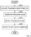
- Fig. 2 shows a processing flow using the information transmission system of the present invention.
- An information transmission system 300 transmits information by using a mud pulse pressure signal 900 (a signal to be transmitted in the form of a pressure pulse using mud as a transmission medium) to transmit information between a transmitter 100 located in an excavation part 400 of an underground excavator and a receiver 200 located on the ground.
- the information transmission system 300 uses a difference in mud pressure as a signal, and transmits information by a pressure-changed pulse (pressure pulse).
- Pressure is applied to mud from the ground side for excavation. When the resistance to flow of mud is changed on the excavation part 400 side, the pressure of the mud changes.
- the pressure pulse may be generated by changing the resistance to the flow of mud.
- the transmitter 100 comprises a transmission information acquisition part 110 for acquiring information, and a pressure pulse generation part 120.
- the excavation part 400 includes an information processing device for obtaining information such as a tilt angle, an azimuth angle, a dip angle, and a tool face of the excavation part 400 from data which have been obtained from an acceleration sensor, a magnetic sensor, a temperature sensor, and the like.
- the transmission information acquisition part 110 acquires information to be transmitted to the ground from the information processing device, etc. (S110).
- the information to be acquired may be the tilt angle, the azimuth angle, the dip angle, the tool face, and the temperature themselves, or information on differences from previouslytransmitted information. Since the communication speed based on the mud pulse is very slow as described above, it is advisable to take appropriate measures to reduce the amount of information (number of bits) to be transmitted as much as possible.
- the pressure pulse generation part 120 generates a pressure pulse so that the interval between the pressure pulse and a just preceding or just subsequent pressure pulse is an interval corresponding to information acquired by the transmission information acquisition part 110 (S120).
- a just preceding pressure pulse means that a pressure pulse just before the pressure pulse of interest.
- a just subsequent pressure pulse means that a pressure pulse just after the pressure pulse of interest.
- the pressure pulse generation part 120 may be configured to consume electric power when generating a pressure pulse. Conversely, the pressure pulse generation part 120 may be configured to consume no electric power when generating no pressure pulse. In the case of a modulation method in which a period of time during which no pressure pulse is generated is longer, the power consumption can be reduced by performing such setting that electric power is consumed only when a pressure pulse is generated.
- the pressure pulse generation part 120 may be configured to generate a pressure pulse having a predetermined certain pulse width.
- the predetermined certain pulse width in the case of the setting that electric power is consumed only when a pressure pulse is generated, by setting "the predetermined certain pulse width" to a minimum pulse width that enables the pressure pulse detection part 210 of the receiver 200 to detect a pressure pulse, it makes it easy to reduce power consumption.
- other methods may be used.
- a method of consuming electric power when the presence or absence of a pressure pulse is altered, and the like may be adopted.
- the receiver 200 comprises a pressure pulse detection part 210 and a reception information output part 220.
- the pressure pulse detection part 210 detects a pressure pulse (S210).
- the reception information output part 220 outputs information corresponding to the interval between a detected pressure pulse and a pressure pulse just before or just after the detected pressure pulse (S220). It may be appropriately selected whether the interval between the detected pressure pulse and the just preceding pressure pulse is made to correspond to the information or the interval between the detected pressure pulse and the just subsequent pressure pulse is made to correspond to the information.
- the interval between pressure pulses is made to correspond to information to be transmitted.
- this modulation is characterized in that the period of time during which no electric power is consumed corresponds to the information to be transmitted.
- a period of time during which the excavation part 400 does not execute the control of changing the mud pressure corresponds to the information.
- Fig. 3 shows an example in which 1-bit information is subjected to pulse position modulation.
- the pulse position is different between the case of "0" and the case of "1".
- a period of time T 1 is required to transmit 1 bit.
- Fig. 4 shows an example in which 2-bit information is subjected to pulse position modulation.
- the pulse position is different among the cases of "00", “01", “10", and "11".
- a period of time T 2 is required to transmit 2 bits.
- Fig. 5 shows an example in which 3-bit information is subjected to pulse position modulation.
- FIG. 3 shows an example in which 1-bit information is subjected to pulse position modulation.
- the pulse position is different between the case of "0" and the case of "1".
- a period of time T 1 is required to transmit 1 bit.
- Fig. 4 shows an example in which 2-bit information is subjected to pulse position modulation.
- the pulse position is different among the cases of "00", “01", “10", and "11
- the pulse position is different among the cases of "000”, “001”, “010”, “011”, “100”, “101”, “110”, and “111".
- a period of time T 31 is required to transmit 3 bits.
- a period of time A before a pulse and a period of time B after the pulse determine the position of the pulse.
- T 2 2 ⁇ T 1
- a period of time T n required when n-bit information is likewise subjected to pulse position modulation satisfies T n -2 n-1 ⁇ T 1 . Therefore, when a large number of bits are subjected to pulse position modulation in a lump, the amount of information that can be transmitted per unit time is reduced (the communication speed slows down).
- Fig. 6 shows another example in which 3-bit information is subjected to pulse position modulation.
- the pulse position is likewise different among the cases of "000”, “001”, “010”, “011”, “100”, “101”, “110”, and “111”.
- a period of time C and a period of time D in which no pulse exists are present regardless of the information to be transmitted, and a period of time A before a pulse and a period of time B after the pulse determine the position of the pulse.
- the period of time C and the period of time D in which no pulse exists are not shown, but it is general to set the period of time C and the period of time D for detection of timing or the like.
- the pulse position is changed with a half of the width of the pulse being set as a unit. In this example, a period of time T 32 is required to transmit 3 bits.
- Fig. 7 shows pulses in the case where "000011” is transmitted by the pulse position modulation shown in Fig. 6 .
- Fig. 8 shows pulses in the case where "010110" is transmitted by the pulse position modulation shown in Fig. 6 .
- 6 bits are transmitted in a period of time of 2 ⁇ T 32 .
- Fig. 9 shows an example of a modulation method that specifies information based on a period of time before a pulse.
- the period of time A before each pulse is different among the cases of "000”, “001”, “010”, “011”, “100”, “101”, “110”, and “111”, and each signal ends when a certain period of time D has elapsed after the pulse. Therefore, in the case of "111" which is the longest signal, the period of time required to transmit 3 bits is T 32 , but in the other cases, 3-bit information can be transmitted in a period of time shorter than T 32 .
- Fig. 10 shows the difference between a case where "000011” is transmitted by the modulation of Fig. 6 and a case where "000011” is transmitted by the modulation of Fig. 9 .
- Fig. 11 shows the difference between a case where "010110” is transmitted by the modulation of Fig. 6 and a case where "010110” is transmitted by the modulation of Fig. 9 .
- P represents the case of the modulation of Fig. 6
- “N” represents the case of the modulation of Fig. 9 .
- the period of time required to transmit 6-bit information is shortened. Note that it is the same in both the examples of Figs. 6 and 9 to send two pulses for transmission of 6-bit information. Therefore, the electric power required to transmit 1-bit information is the same in both the examples.
- Fig. 12 shows an example of a modulation method that specifies information by a period of time after a pulse.
- a period of time B after a pulse is different among the cases of "000”, “001”, “010”, “011”, “100”, “101”, “110”, and “111”, a certain period of time C exists before each pulse.
- the period of time required to transmit 3 bits is T 32 in the case of "000” which is the longest signal, but in the other cases, 3-bit information can be transmitted in a period of time shorter than T 32 .
- Fig. 13 shows the difference between a case where "000011” is transmitted by the modulation of Fig. 6 and a case where "000011” is transmitted by the modulation of Fig. 12 .
- Fig. 14 shows the difference between a case where "010110” is transmitted by the modulation of Fig. 6 and a case where "010110” is transmitted by the modulation of Fig. 12 .
- P represents the case of the modulation of Fig. 6
- “N” represents the case of the modulation of Fig. 12 .
- the period of time required to transmit 6-bit information is shortened. Note that it is the same in both the examples of Figs. 6 and 12 to send two pulses for transmission of 6-bit information. Therefore, the electric power required to transmit 1-bit information is the same in both the examples.
- the modulation of Fig. 9 is the modulation in the case where an interval from a just preceding pressure pulse is made to correspond to information.
- the period of time D+C+A is an interval from a just preceding pressure pulse, and it corresponds to information "011".
- the period of time D+C+A is an interval from a just preceding pressure pulse, and it corresponds to information "110”.
- the modulation of Fig. 12 is the modulation in the case where an interval from a just subsequent pressure pulse is made to correspond to information.
- the modulation of Fig. 9 is the modulation in the case where an interval from a just preceding pressure pulse is made to correspond to information.
- the period of time D+C+A is an interval from a just preceding pressure pulse, and it corresponds to information "011".
- the period of time D+C+A is an interval from a just preceding pressure pulse, and it corresponds to information "110”.
- the modulation of Fig. 12 is the modulation in the case where an interval from
- the period of time B+D+C is an interval from a just preceding pressure pulse, and it corresponds to information "000".
- the period of time B+D+C is an interval from a just subsequent pressure pulse, and it corresponds to information "010".
- one pulse is used for 3-bit information.
- the number of bits of information to be transmitted by one pulse may be appropriately determined.
- the above description has been made on the assumption that an interval between the falling edge of a preceding pressure pulse and the rising edge of a subsequent pressure pulse is defined as the interval between the pressure pulses.
- an interval between the rising edge of a preceding pressure pulse and the rising edge of a subsequent pressure pulse may be interpreted as the interval between the pressure pulses. In this way, it may be appropriately determined from which position of a preceding pressure pulse to which position of a subsequent pressure pulse is interpreted as the interval between the pressure pulses.
- time from the generation of a pulse until the end of the certain period of time is a standby time for waiting the start of a next certain period of time.
- the standby time becomes longer.
- the position of a pulse is indicated by the time after the generation of the pulse until the end of the certain period of time, the time until the pulse has been generated is a standby time. At this time, when the position of a pulse exists at a later timing in the certain period of time, the standby time becomes longer.
- an interval from a just preceding or just subsequent pressure pulse is made to correspond to information to be transmitted. Therefore, the standby time can be eliminated, so that the communication speed can be improved. Further, since the number of bits that can be transmitted by one pulse is the same, the power consumption required to transmit 1-bit information is the same as the pulse position modulation.
Abstract
Description
- The present invention relates to an information transmission system, a transmitter, a receiver, and an information transmission method for transmitting information by using a mud pulse pressure signal (a signal to be transmitted in the form of a pressure pulse using mud as a transmission medium) to transmit information between a transmitter located in an excavation part of an underground excavator and a receiver located on the ground.
-
US 7,573,397 B2 (hereinafter referred to as "Patent Literature 1") discloses that pulse position modulation is used in a communication method using a difference in mud pressure.Patent Literature 1 discloses an underground excavator located in the ground, a receiver located on the ground, etc. - However, communication using a mud pulse pressure signal can transmit only about one pulse per second, so that the communication speed (the number of bits that can be transmitted per second) is extremely slow as compared with general communication. The present invention has an object to increase the communication speed of a communication method using a mud pulse as much as possible.
- An information transmission system of the present invention transmits information by using a mud pulse pressure signal to transmit information between a transmitter located in an excavation part of an underground excavator and a receiver located on the ground. The transmitter comprises a transmission information acquisition part for acquiring information, and a pressure pulse generation part. The pressure pulse generation part generates a pressure pulse so that an interval between the pressure pulse and a just preceding or just subsequent pressure pulse is an interval corresponding to the information acquired by the transmission information acquisition part. The receiver comprises a pressure pulse detection part for detecting a pressure pulse, and a reception information output part. The reception information output part outputs information corresponding to the interval between the detected pressure pulse and a just preceding or just subsequent pressure pulse.
- In the pulse position modulation, information is transmitted according to a timing (position) at which a pulse exists in a certain period of time. In the information transmission system of the present invention, an interval from a just preceding or just subsequent pressure pulse is made to correspond to information to be transmitted. Therefore, a standby time can be eliminated, and thus the communication speed can be improved.
-
-
FIG. 1 is a diagram showing a configuration example of an information transmission system of the present invention; -
FIG. 2 is a diagram showing a processing flow using the information transmission system of the present invention: -
FIG. 3 is a diagram showing an example in which 1-bit information is subjected to pulse position modulation; -
FIG. 4 is a diagram showing an example in which 2-bit information is subjected to pulse position modulation; -
FIG. 5 is a diagram showing an example in which 3-bit information is subjected to pulse position modulation; -
FIG. 6 is a diagram showing another example in which 3-bit information is subjected to pulse position modulation; -
FIG. 7 is a diagram showing pulses when "000011" is transmitted by the pulse position modulation shown inFIG. 6 ; -
FIG. 8 is a diagram showing pulses when "010110" is transmitted by the pulse position modulation shown inFIG. 6 ; -
FIG. 9 is a diagram showing an example of a modulation method that specifies information based on a period of time before a pulse; -
FIG. 10 is a diagram showing a difference between a case where "000011" is transmitted by the modulation ofFIG. 6 and a case where "000011" is transmitted by the modulation ofFIG. 9 ; -
FIG. 11 is a diagram showing a difference between a case where "010110" is transmitted by the modulation ofFIG. 6 and a case where "010110" is transmitted by the modulation ofFIG. 9 ; -
FIG. 12 is a diagram showing an example of a modulation method that specifies information based on a period of time after a pulse; -
FIG. 13 is a diagram showing a difference between a case where "000011" is transmitted by the modulation ofFIG. 6 and a case where "000011" is transmitted by the modulation ofFIG. 12 ; and -
FIG. 14 is a diagram showing a difference between a case where "010110" is transmitted by the modulation ofFIG. 6 and a case where "010110" is transmitted by the modulation ofFIG. 12 . -
Fig. 1 shows a configuration example of an information transmission system of the present invention.Fig. 2 shows a processing flow using the information transmission system of the present invention. Aninformation transmission system 300 transmits information by using a mud pulse pressure signal 900 (a signal to be transmitted in the form of a pressure pulse using mud as a transmission medium) to transmit information between atransmitter 100 located in anexcavation part 400 of an underground excavator and areceiver 200 located on the ground. In other words, theinformation transmission system 300 uses a difference in mud pressure as a signal, and transmits information by a pressure-changed pulse (pressure pulse). Pressure is applied to mud from the ground side for excavation. When the resistance to flow of mud is changed on theexcavation part 400 side, the pressure of the mud changes. The pressure pulse may be generated by changing the resistance to the flow of mud. - The
transmitter 100 comprises a transmissioninformation acquisition part 110 for acquiring information, and a pressurepulse generation part 120. Although not shown, theexcavation part 400 includes an information processing device for obtaining information such as a tilt angle, an azimuth angle, a dip angle, and a tool face of theexcavation part 400 from data which have been obtained from an acceleration sensor, a magnetic sensor, a temperature sensor, and the like. The transmissioninformation acquisition part 110 acquires information to be transmitted to the ground from the information processing device, etc. (S110). The information to be acquired may be the tilt angle, the azimuth angle, the dip angle, the tool face, and the temperature themselves, or information on differences from previouslytransmitted information. Since the communication speed based on the mud pulse is very slow as described above, it is advisable to take appropriate measures to reduce the amount of information (number of bits) to be transmitted as much as possible. - The pressure
pulse generation part 120 generates a pressure pulse so that the interval between the pressure pulse and a just preceding or just subsequent pressure pulse is an interval corresponding to information acquired by the transmission information acquisition part 110 (S120). "A just preceding pressure pulse" means that a pressure pulse just before the pressure pulse of interest. "A just subsequent pressure pulse" means that a pressure pulse just after the pressure pulse of interest. The pressurepulse generation part 120 may be configured to consume electric power when generating a pressure pulse. Conversely, the pressurepulse generation part 120 may be configured to consume no electric power when generating no pressure pulse. In the case of a modulation method in which a period of time during which no pressure pulse is generated is longer, the power consumption can be reduced by performing such setting that electric power is consumed only when a pressure pulse is generated. Further, the pressurepulse generation part 120 may be configured to generate a pressure pulse having a predetermined certain pulse width. In particular, in the case of the setting that electric power is consumed only when a pressure pulse is generated, by setting "the predetermined certain pulse width" to a minimum pulse width that enables the pressurepulse detection part 210 of thereceiver 200 to detect a pressure pulse, it makes it easy to reduce power consumption. However, if there is little need to reduce power consumption, other methods may be used. Further, a method of consuming electric power when the presence or absence of a pressure pulse is altered, and the like may be adopted. - The
receiver 200 comprises a pressurepulse detection part 210 and a receptioninformation output part 220. The pressurepulse detection part 210 detects a pressure pulse (S210). The receptioninformation output part 220 outputs information corresponding to the interval between a detected pressure pulse and a pressure pulse just before or just after the detected pressure pulse (S220). It may be appropriately selected whether the interval between the detected pressure pulse and the just preceding pressure pulse is made to correspond to the information or the interval between the detected pressure pulse and the just subsequent pressure pulse is made to correspond to the information. - In the modulation adopted in the present invention, the interval between pressure pulses is made to correspond to information to be transmitted. In particular, when the pressure
pulse generation part 120 consumes electric power only when generating a pressure pulse, this modulation is characterized in that the period of time during which no electric power is consumed corresponds to the information to be transmitted. In other words, a period of time during which theexcavation part 400 does not execute the control of changing the mud pressure corresponds to the information. - Next, the pulse position modulation and the modulation adopted by the present invention will be described.
Fig. 3 shows an example in which 1-bit information is subjected to pulse position modulation. InFig. 3 , the pulse position is different between the case of "0" and the case of "1". In this example, a period of time T1 is required to transmit 1 bit.Fig. 4 shows an example in which 2-bit information is subjected to pulse position modulation. InFig. 4 , the pulse position is different among the cases of "00", "01", "10", and "11". In this example, a period of time T2 is required to transmit 2 bits.Fig. 5 shows an example in which 3-bit information is subjected to pulse position modulation. InFIG. 5 , the pulse position is different among the cases of "000", "001", "010", "011", "100", "101", "110", and "111". In this example, a period of time T31 is required to transmit 3 bits. Further, a period of time A before a pulse and a period of time B after the pulse determine the position of the pulse. - In the examples of
Figs. 3 to 5 , T2=2×T1, T31=2×T2=4×T1. Likewise, a period of time T4 required when 4-bit information is subjected to pulse position modulation satisfies T4=2×T31=4×T2=8×T1. A period of time Tn required when n-bit information is likewise subjected to pulse position modulation satisfies Tn-2n-1×T1. Therefore, when a large number of bits are subjected to pulse position modulation in a lump, the amount of information that can be transmitted per unit time is reduced (the communication speed slows down). On the other hand, in the case where power is consumed only when a pulse is transmitted, 3 bits can be transmitted in the example ofFig. 5 with the power to be consumed for transmission of 1 bit in the example ofFig. 3 . In other words, when a large number of bits are subjected to pulse position modulation in a lump, the power required to transmit 1-bit information can be reduced. As described above, the pulse position modulation has a disadvantage that the communication speed becomes slow, but has an advantage that the power consumption of the transmitter which is installed in theexcavation part 400 and operates with a battery can be easily reduced. -
Fig. 6 shows another example in which 3-bit information is subjected to pulse position modulation. InFig. 6 , the pulse position is likewise different among the cases of "000", "001", "010", "011", "100", "101", "110", and "111". InFig. 6 , a period of time C and a period of time D in which no pulse exists are present regardless of the information to be transmitted, and a period of time A before a pulse and a period of time B after the pulse determine the position of the pulse. In the example ofFig. 5 , the period of time C and the period of time D in which no pulse exists are not shown, but it is general to set the period of time C and the period of time D for detection of timing or the like. Further, in the example ofFig. 6 , the pulse position is changed with a half of the width of the pulse being set as a unit. In this example, a period of time T32 is required to transmit 3 bits. -
Fig. 7 shows pulses in the case where "000011" is transmitted by the pulse position modulation shown inFig. 6 .Fig. 8 shows pulses in the case where "010110" is transmitted by the pulse position modulation shown inFig. 6 . In both the cases, 6 bits are transmitted in a period of time of 2×T32. -
Fig. 9 shows an example of a modulation method that specifies information based on a period of time before a pulse. In the example ofFig. 9 , the period of time A before each pulse is different among the cases of "000", "001", "010", "011", "100", "101", "110", and "111", and each signal ends when a certain period of time D has elapsed after the pulse. Therefore, in the case of "111" which is the longest signal, the period of time required to transmit 3 bits is T32, but in the other cases, 3-bit information can be transmitted in a period of time shorter than T32. -
Fig. 10 shows the difference between a case where "000011" is transmitted by the modulation ofFig. 6 and a case where "000011" is transmitted by the modulation ofFig. 9 .Fig. 11 shows the difference between a case where "010110" is transmitted by the modulation ofFig. 6 and a case where "010110" is transmitted by the modulation ofFig. 9 . In both the figures, "P" represents the case of the modulation ofFig. 6 , and "N" represents the case of the modulation ofFig. 9 . In both the cases, it can be seen that the period of time required to transmit 6-bit information is shortened. Note that it is the same in both the examples ofFigs. 6 and9 to send two pulses for transmission of 6-bit information. Therefore, the electric power required to transmit 1-bit information is the same in both the examples. -
Fig. 12 shows an example of a modulation method that specifies information by a period of time after a pulse. In the example ofFig. 12 , a period of time B after a pulse is different among the cases of "000", "001", "010", "011", "100", "101", "110", and "111", a certain period of time C exists before each pulse. In the example ofFig. 12 , the period of time required to transmit 3 bits is T32 in the case of "000" which is the longest signal, but in the other cases, 3-bit information can be transmitted in a period of time shorter than T32. -
Fig. 13 shows the difference between a case where "000011" is transmitted by the modulation ofFig. 6 and a case where "000011" is transmitted by the modulation ofFig. 12 .Fig. 14 shows the difference between a case where "010110" is transmitted by the modulation ofFig. 6 and a case where "010110" is transmitted by the modulation ofFig. 12 . In both the figures, "P" represents the case of the modulation ofFig. 6 , and "N" represents the case of the modulation ofFig. 12 . In both the cases, it can be seen that the period of time required to transmit 6-bit information is shortened. Note that it is the same in both the examples ofFigs. 6 and12 to send two pulses for transmission of 6-bit information. Therefore, the electric power required to transmit 1-bit information is the same in both the examples. - When applied to the
information transmission system 300 of the present invention, the modulation ofFig. 9 is the modulation in the case where an interval from a just preceding pressure pulse is made to correspond to information. For example, in the example ofFig. 10 , the period of time D+C+A is an interval from a just preceding pressure pulse, and it corresponds to information "011". In the example ofFig. 11 , the period of time D+C+A is an interval from a just preceding pressure pulse, and it corresponds to information "110". Further, the modulation ofFig. 12 is the modulation in the case where an interval from a just subsequent pressure pulse is made to correspond to information. For example, in the example ofFig. 13 , the period of time B+D+C is an interval from a just preceding pressure pulse, and it corresponds to information "000". In the example ofFig. 14 , the period of time B+D+C is an interval from a just subsequent pressure pulse, and it corresponds to information "010". - In the description with reference to
Figs. 9 to 14 , one pulse is used for 3-bit information. However, the number of bits of information to be transmitted by one pulse may be appropriately determined. Further, the above description has been made on the assumption that an interval between the falling edge of a preceding pressure pulse and the rising edge of a subsequent pressure pulse is defined as the interval between the pressure pulses. However, an interval between the rising edge of a preceding pressure pulse and the rising edge of a subsequent pressure pulse may be interpreted as the interval between the pressure pulses. In this way, it may be appropriately determined from which position of a preceding pressure pulse to which position of a subsequent pressure pulse is interpreted as the interval between the pressure pulses. - In the pulse position modulation, information is transmitted according to a timing (position) at which a pulse exists in a certain period of time. Therefore, time from the generation of a pulse until the end of the certain period of time is a standby time for waiting the start of a next certain period of time. In particular, when the position of a pulse exists at an early timing in the certain period of time, the standby time becomes longer. Further, when the position of a pulse is indicated by the time after the generation of the pulse until the end of the certain period of time, the time until the pulse has been generated is a standby time. At this time, when the position of a pulse exists at a later timing in the certain period of time, the standby time becomes longer. In the information transmission system of the present invention, an interval from a just preceding or just subsequent pressure pulse is made to correspond to information to be transmitted. Therefore, the standby time can be eliminated, so that the communication speed can be improved. Further, since the number of bits that can be transmitted by one pulse is the same, the power consumption required to transmit 1-bit information is the same as the pulse position modulation.
Claims (8)
- An information transmission system for transmitting information as a pressure pulse by using a mud pulse pressure signal to transmit information between a transmitter located in an excavation part of an underground excavator and a receiver located on the ground, wherein the transmitter comprises:a transmission information acquisition part for acquiring information; anda pressure pulse generation part for generating a pressure pulse so that an interval between the pressure pulse and a just preceding pressure pulse is an interval corresponding to the information acquired by the transmission information acquisition part, and wherein the receiver comprises:a pressure pulse detection part for detecting the pressure pulse; anda reception information output part for outputting information corresponding to an interval between the detected pressure pulse and a just preceding pressure pulse.
- An information transmission system for transmitting information as a pressure pulse by using a mud pulse pressure signal to transmit information between a transmitter located in an excavation part of an underground excavator and a receiver located on the ground, wherein the transmitter comprises:a transmission information acquisition part for acquiring information; anda pressure pulse generation part for generating a pressure pulse so that an interval between the pressure pulse and a just subsequent pressure pulse is an interval corresponding to the information acquired by the transmission information acquisition part, and wherein the receiver comprises:a pressure pulse detection part for detecting the pressure pulse; anda reception information output part for outputting information corresponding to an interval between the detected pressure pulse and a just subsequent pressure pulse.
- A transmitter that is located in an excavation part of an underground excavator and transmits information as a pressure pulse by using a mud pulse pressure signal, comprising:a transmission information acquisition part for acquiring information; anda pressure pulse generation part for generating a pressure pulse so that an interval between the pressure pulse and a just preceding or just subsequent pressure pulse is an interval corresponding to the information acquired by the transmission information acquisition part.
- The transmitter according to claim 3, wherein the pressure pulse generation part consumes electric power when generating a pressure pulse.
- The transmitter according to claim 4, wherein the pressure pulse generation part generates a pressure pulse having a predetermined certain pulse width.
- A receiver for receiving, on ground, information transmitted from a transmitter that is located in an excavation part of an underground excavator and transmits information by using a mud pulse pressure signal, comprising:a pressure pulse detection part for detecting a pressure pulse; anda reception information output part for outputting information corresponding to an interval between the detected pressure pulse and a just preceding or just subsequent pressure pulse.
- An information transmission method for transmitting information as a pressure pulse by using a mud pulse pressure signal to transmit information between a transmitter located in an excavation part of an underground excavator and a receiver located on the ground, wherein the transmitter executes:a transmission information acquisition step of acquiring information; anda pressure pulse generation step of generating a pressure pulse so that an interval between the pressure pulse and a just preceding pressure pulse is an interval corresponding to the information acquired in the transmission information acquisition step, and wherein the receiver executes:a pressure pulse detection step of detecting the pressure pulse; anda reception information output step of outputting information corresponding to an interval between the detected pressure pulse and a just preceding pressure pulse.
- An information transmission method for transmitting information as a pressure pulse by using a mud pulse pressure signal to transmit information between a transmitter located in an excavation part of an underground excavator and a receiver located on the ground, wherein the transmitter executes:a transmission information acquisition step of acquiring information; anda pressure pulse generation step of generating a pressure pulse so that an interval between the pressure pulse and a just subsequent pressure pulse is an interval corresponding to the information acquired in the transmission information acquisition step, and wherein the receiver executes:a pressure pulse detection step of detecting the pressure pulse; anda reception information output step of outputting information corresponding to an interval between the detected pressure pulse and a just subsequent pressure pulse.
Applications Claiming Priority (2)
| Application Number | Priority Date | Filing Date | Title |
|---|---|---|---|
| US202163134643P | 2021-01-07 | 2021-01-07 | |
| US17/337,838 US20220213788A1 (en) | 2021-01-07 | 2021-06-03 | Information transmission system, transmitter, receiver, and information transmission method |
Publications (2)
| Publication Number | Publication Date |
|---|---|
| EP4063614A2 true EP4063614A2 (en) | 2022-09-28 |
| EP4063614A3 EP4063614A3 (en) | 2022-11-09 |
Family
ID=78845055
Family Applications (1)
| Application Number | Title | Priority Date | Filing Date |
|---|---|---|---|
| EP21214019.8A Pending EP4063614A3 (en) | 2021-01-07 | 2021-12-13 | Information transmission system, transmitter, receiver, and information transmission method |
Country Status (1)
| Country | Link |
|---|---|
| EP (1) | EP4063614A3 (en) |
Citations (1)
| Publication number | Priority date | Publication date | Assignee | Title |
|---|---|---|---|---|
| US7573397B2 (en) | 2006-04-21 | 2009-08-11 | Mostar Directional Technologies Inc | System and method for downhole telemetry |
Family Cites Families (2)
| Publication number | Priority date | Publication date | Assignee | Title |
|---|---|---|---|---|
| US20060215491A1 (en) * | 2005-03-21 | 2006-09-28 | Hall Brent S | System and method for transmitting information through a fluid medium |
| AU2014415645C1 (en) * | 2014-12-29 | 2018-06-21 | Halliburton Energy Services, Inc. | Mud pulse telemetry using Gray coding |
-
2021
- 2021-12-13 EP EP21214019.8A patent/EP4063614A3/en active Pending
Patent Citations (1)
| Publication number | Priority date | Publication date | Assignee | Title |
|---|---|---|---|---|
| US7573397B2 (en) | 2006-04-21 | 2009-08-11 | Mostar Directional Technologies Inc | System and method for downhole telemetry |
Also Published As
| Publication number | Publication date |
|---|---|
| EP4063614A3 (en) | 2022-11-09 |
Similar Documents
| Publication | Publication Date | Title |
|---|---|---|
| US8972638B2 (en) | Serial data communication system and serial data communication method | |
| EP3502741B1 (en) | Obstacle detection sensor | |
| US11977179B2 (en) | Leakage detection system and method | |
| US7844020B2 (en) | Transmission system, transmitter, receiver, and transmission method | |
| EP4063614A2 (en) | Information transmission system, transmitter, receiver, and information transmission method | |
| US20220213788A1 (en) | Information transmission system, transmitter, receiver, and information transmission method | |
| US20010053188A1 (en) | Transmitting circuit and method thereof, receiving circuit and method thereof, and data communication apparatus | |
| KR101777011B1 (en) | Apparatus and method for processing radar signal in accordance with the energy of the radar sensor | |
| US20180077269A1 (en) | Data transmitting/receiving apparatus and data transmitting/receiving method | |
| CN107238830A (en) | Wireless device is close to method for detecting | |
| US5367543A (en) | Circuit for detecting synchronizing signal in frame synchronization data transmission | |
| US8848848B2 (en) | Transmission timing adjustment in radio systems | |
| JP5751290B2 (en) | Data receiving device and method for determining same bit length of received bit string | |
| CA2328256A1 (en) | Methods and apparatus for exchanging data | |
| US8681913B2 (en) | Reception circuit | |
| US8175194B2 (en) | Signal receiving apparatus and signal processing method | |
| US6970527B2 (en) | Transmitting circuit and method thereof, receiving circuit and method thereof, and data communication apparatus | |
| US4078204A (en) | Di-phase pulse receiving system | |
| CN113296101A (en) | Ultrasonic ranging method, device and system and computer readable storage medium | |
| GB2421330A (en) | Clock retraining method for receivers | |
| KR100240250B1 (en) | Data transmission apparatus and the method by address selection using clock line | |
| US20230400573A1 (en) | System and method for object detecting using ultrasonic sensor | |
| US20230231561A1 (en) | Clock pattern detection and correction | |
| JP2006128800A (en) | One-wire data communication method, and one-wire data transmitter/receiver employing that communication method | |
| EP1665621B1 (en) | Method and system for controlling a receiver in a digital communication system |
Legal Events
| Date | Code | Title | Description |
|---|---|---|---|
| PUAI | Public reference made under article 153(3) epc to a published international application that has entered the european phase |
Free format text: ORIGINAL CODE: 0009012 |
|
| STAA | Information on the status of an ep patent application or granted ep patent |
Free format text: STATUS: THE APPLICATION HAS BEEN PUBLISHED |
|
| AK | Designated contracting states |
Kind code of ref document: A2 Designated state(s): AL AT BE BG CH CY CZ DE DK EE ES FI FR GB GR HR HU IE IS IT LI LT LU LV MC MK MT NL NO PL PT RO RS SE SI SK SM TR |
|
| PUAL | Search report despatched |
Free format text: ORIGINAL CODE: 0009013 |
|
| AK | Designated contracting states |
Kind code of ref document: A3 Designated state(s): AL AT BE BG CH CY CZ DE DK EE ES FI FR GB GR HR HU IE IS IT LI LT LU LV MC MK MT NL NO PL PT RO RS SE SI SK SM TR |
|
| RIC1 | Information provided on ipc code assigned before grant |
Ipc: E21B 47/18 20120101AFI20220930BHEP |
|
| STAA | Information on the status of an ep patent application or granted ep patent |
Free format text: STATUS: REQUEST FOR EXAMINATION WAS MADE |
|
| 17P | Request for examination filed |
Effective date: 20230509 |
|
| RBV | Designated contracting states (corrected) |
Designated state(s): AL AT BE BG CH CY CZ DE DK EE ES FI FR GB GR HR HU IE IS IT LI LT LU LV MC MK MT NL NO PL PT RO RS SE SI SK SM TR |
|
| STAA | Information on the status of an ep patent application or granted ep patent |
Free format text: STATUS: EXAMINATION IS IN PROGRESS |
|
| 17Q | First examination report despatched |
Effective date: 20230829 |
|
| STAA | Information on the status of an ep patent application or granted ep patent |
Free format text: STATUS: THE APPLICATION IS DEEMED TO BE WITHDRAWN |