EP4063576A1 - Waschtischanordnung - Google Patents
Waschtischanordnung Download PDFInfo
- Publication number
- EP4063576A1 EP4063576A1 EP21164564.3A EP21164564A EP4063576A1 EP 4063576 A1 EP4063576 A1 EP 4063576A1 EP 21164564 A EP21164564 A EP 21164564A EP 4063576 A1 EP4063576 A1 EP 4063576A1
- Authority
- EP
- European Patent Office
- Prior art keywords
- drain
- cavity
- wall
- overflow
- channel
- Prior art date
- Legal status (The legal status is an assumption and is not a legal conclusion. Google has not performed a legal analysis and makes no representation as to the accuracy of the status listed.)
- Granted
Links
Images



Classifications
-
- E—FIXED CONSTRUCTIONS
- E03—WATER SUPPLY; SEWERAGE
- E03C—DOMESTIC PLUMBING INSTALLATIONS FOR FRESH WATER OR WASTE WATER; SINKS
- E03C1/00—Domestic plumbing installations for fresh water or waste water; Sinks
- E03C1/12—Plumbing installations for waste water; Basins or fountains connected thereto; Sinks
- E03C1/14—Wash-basins connected to the waste-pipe
-
- E—FIXED CONSTRUCTIONS
- E03—WATER SUPPLY; SEWERAGE
- E03C—DOMESTIC PLUMBING INSTALLATIONS FOR FRESH WATER OR WASTE WATER; SINKS
- E03C1/00—Domestic plumbing installations for fresh water or waste water; Sinks
- E03C1/12—Plumbing installations for waste water; Basins or fountains connected thereto; Sinks
- E03C1/18—Sinks, whether or not connected to the waste-pipe
- E03C1/182—Sinks, whether or not connected to the waste-pipe connected to the waste-pipe
-
- E—FIXED CONSTRUCTIONS
- E03—WATER SUPPLY; SEWERAGE
- E03C—DOMESTIC PLUMBING INSTALLATIONS FOR FRESH WATER OR WASTE WATER; SINKS
- E03C1/00—Domestic plumbing installations for fresh water or waste water; Sinks
- E03C1/12—Plumbing installations for waste water; Basins or fountains connected thereto; Sinks
- E03C1/22—Outlet devices mounted in basins, baths, or sinks
- E03C1/23—Outlet devices mounted in basins, baths, or sinks with mechanical closure mechanisms
- E03C1/232—Outlet devices mounted in basins, baths, or sinks with mechanical closure mechanisms combined with overflow devices
Definitions
- the DE 10 2008 044 637 a washbasin which can be connected to a drain pipe.
- the washbasin has a chamber into which the water flows. The chamber is then followed by the drain pipe.
- the DE 10 2008 044 637 has two major disadvantages.
- the shape of the washbasin with the chamber can only be produced with great effort.
- Various undercuts increase the manufacturing effort significantly, especially when manufacturing the ceramic washbasin.
- it is disadvantageous that the required installation space is comparatively large. This is due in particular to the arrangement of the drain pipe in the form of a pipe bend.
- washstands with an overflow element are also known from the prior art.
- the EP 1 754 838 a drain arrangement of a washbasin with an overflow element, which connects to the washbasin to the rear.
- Such overflow elements are typically behind a pretext arranged and very difficult to access in the installation position.
- the invention is based on the object of specifying a washbasin arrangement which overcomes the disadvantages of the prior art.
- one object of the present invention is to specify a washstand arrangement with an overflow element, the washstand arrangement being designed to be more compact overall.
- a washbasin arrangement comprises a washbasin with a water basin, a cavity and a drain passage which extends from the water basin into the cavity, and a drain element arranged in the cavity for draining water from the drain passage and for feeding the water into a drain line.
- the washbasin has a rear wall, with which the washbasin can be brought into contact with a connection structure on the building side in the installed position, the cavity being open in the region of a rear wall of the washbasin, and the drain element having a wall structure which extends over the cross section of the drain passage extends.
- An overflow inlet opening is arranged on the wall structure.
- the overflow inlet opening is followed by an overflow channel with an overflow edge.
- a drain opening is arranged in the wall structure, which is connected to a drain channel that can be opened and closed with a check valve.
- the arrangement of the drain element with the check valve and the overflow channel with the overflow edge in the cavity has the advantage that a very compact wash stand arrangement can be created. This is particularly so in comparison with the arrangements where the overflow unit is located behind a curtain. In addition, the ease of maintenance is increased.
- the object according to claim 2 has the same advantages as the object according to claim 1.
- the outflow element according to claim 2 also has a wall structure which extends over the cross section of the outflow passage, with an overflow inlet opening being arranged in the wall structure, which is connected to the overflow channel with the overflow edge, and with a drain opening in the wall structure, which is a with a shut-off valve that can be opened and closed.
- the water in the water basin rises and flows into the overflow channel via the overflow inlet opening.
- the water then rises in the water basin and in the overflow channel.
- the overflow edge defines the maximum water level in the water basin. When the maximum water level is reached, the water then flows over the overflow edge.
- the height of the overflow edge defines the maximum storage height.
- the overflow channel preferably extends upwards in the installed position in the cavity.
- the overflow channel is preferably located completely in the cavity.
- the drainage passage from the water basin is preferably arranged on a side wall of the water basin and extends essentially backwards away from the water basin when viewed in the installed position.
- the drain passage preferably has a slight incline of at most 20° to the horizontal.
- the check valve is in the cavity and/or in the drain passage.
- the water basin is preferably delimited by an upper edge lying horizontally in the installed position.
- the edge spans a reference plane.
- the overflow edge is at a distance of 3 to 6 centimeters from the reference plane, seen at right angles to the reference plane.
- the entire drain element lies substantially entirely within the cavity.
- the drain element does not penetrate a plane which is spanned by said rear wall.
- the drain element does not protrude downwards from the cavity. If the drain element has a drain connector, this can be arranged in such a way that it protrudes out of the cavity as the only element of the drain element.
- the drain socket can protrude from the hollow space to the rear and/or downward out of the hollow space. Apart from the drain pipe, however, all other elements are preferably located inside the cavity.
- the washbasin preferably also has a bottom wall, the bottom wall being designed to be open downwards in the region of the cavity in the installed position, and the drain element not projecting downwards beyond a plane spanned by the bottom wall. If the drain element has a drain connector, this can, as already mentioned, be arranged in such a way that it is the only element of the drain element that protrudes out of the cavity and, depending on the design, penetrates the plane spanned by the bottom wall.
- the overflow channel extends exclusively above said plane spanned by the bottom wall, as seen in the installed position.
- the cavity connects to the drain passage.
- the cavity has a first space section and a second space section.
- the first space section lies between the drain passage and the second space section.
- the bearing wall described herein preferably extends, viewed from the first space section, into the second space section.
- the overflow edge is preferably in the second space section. The second Viewed in the installed position, the space section extends upwards with respect to the first space section.
- Said wall area extends with its surface essentially in said reference plane.
- the overflow channel and the drain channel flow into one another and continue as a common channel to a drain connection, the opening point of the overflow channel and the drain channel being in said cavity.
- the drain connector is particularly preferably arranged in such a way that it does not penetrate through a plane spanned by the rear wall.
- the drain connection is either completely in the cavity or protrudes downwards out of the cavity.
- the downcomer is the only element of the downcomer that protrudes from the cavity, with the exception of the downcomer, the downcomer lying entirely within the cavity.
- the drain socket is used to connect to a waste water pipe.
- the drain socket is arranged in the cavity.
- the shut-off valve is preferably located in front of the drain opening or in the drain channel, viewed in the flow direction of the water.
- the drain opening comes to lie centrally in the wall structure as seen from the drain passage and with a lower edge at the level of or below a lower wall of the drain passage.
- the overflow inlet opening is preferably located laterally next to the drain opening and comes to lie with a lower edge at the same level as or below a lower wall of the drain passage.
- the wall structure is preferably shaped in such a way that the water to be drained does not accumulate in front of the wall structure, but is always fed to the drain opening.
- the overflow channel is surrounded by a wall on the side, with the Wall extending upwardly over the wall structure and a partition wall having the spill edge extending across the interior space defined by the wall.
- the wall of the overflow channel preferably extends upwards away from the wall structure.
- the overflow channel is preferably closed at the top with a cover, the inside of the cover being at a distance from the overflow edge.
- the cover has the advantage that the wall can be shortened mechanically if necessary, and the overflow channel can then be closed with the cover.
- the drain element can thus be easily adapted to different types of washbasins.
- two overflow inlet openings and two overflow channels are provided. Said drain opening with the drain channel is located between the two overflow inlet openings or overflow channels.
- a bearing wall 30 preferably protrudes from the wall structure.
- the bearing wall protrudes into the cavity 4 of the vanity.
- the bearing wall 30 is designed to match the shape of the cavity 4 on the outside.
- the drainage passage for receiving the bearing wall preferably has a somewhat greater extent than in the section which directly adjoins the water basin.
- the bearing wall is designed as a peripheral bearing wall and also serves to accommodate a sealing element that is also peripheral.
- the sealing element is arranged to cooperate with the walls of the cavity and/or with the rear wall.
- the one sealing element is preferably a sealing element that is formed separately from the drain element.
- the at least one sealing element is integrally formed on the insert element.
- the drain element can preferably be brought into connection with the washbasin by means of a cohesive adhesive connection and/or a mechanical connection.
- the mechanical connection is preferably a screw and dowel connection and/or a clamp connection between the drain element and the cavity.
- the vanity 2 has a water basin 3 , a cavity 4 and a drain passage 5 .
- the cavity 4 can only be partially seen behind the drain passage.
- said drain element 6 for draining water arranged.
- the water can be fed to a drain line (not shown) via the drain element 6 .
- the drainage passage extends from the water basin 3 into the cavity 4 in such a way that water can be guided from the water basin into the cavity 4 or to the drainage element 6 .
- the vanity assembly 1 is shown from behind.
- the vanity 2 has a rear wall 7 at the rear. In the installed position, the wash stand 2 can be brought into contact with a connection structure on the building side with the rear wall 7 .
- the washbasin 2 also has a bottom wall 16 .
- the cavity 4 is accessible via the rear wall 7 and the bottom wall 16 .
- the cavity 4 is designed to be open in the area of the rear wall 7 .
- the cavity 4 in the area of the bottom wall 16 is also designed to be open.
- the drain element 6 is arranged substantially entirely in said cavity 4. This means that the drain element 6 projects out of the cavity 4 neither beyond a plane spanned by the rear wall 7 nor beyond a plane spanned by the bottom wall 16 . This apart from a drain pipe or drain connector 21, through which the water is fed to a sewage pipe. Here the drain pipe 21 protrudes downwards out of the cavity 4 . Furthermore, the drain element 6 partially extends into the drain passage 5 .
- the flow element 2 has in the embodiment shown, as in the Figures 2 to 6 shown, a wall structure 8 which extends completely over the cross section of the drain passage 5 in the state connected to the washstand 2 .
- the drain element 2 has two fastening openings 31, with which the drain element 2 can be connected to the washbasin.
- the drain element 2 also has a drain channel 14 and an overflow channel 10 .
- the drain channel 14 and the overflow channel 10 are formed on the wall structure 8 here.
- the drain element 2 is molded from plastic.
- the overflow channel 10 is used to drain water from the water basin 3 when a certain backwater level is reached with the check valve closed.
- the overflow channel 10 has an overflow edge 11 .
- the position of the overflow edge 11 defines the maximum water level in the water basin 3.
- the overflow channel 10 and the overflow edge 11 are also in the cavity 4 in the embodiment shown.
- An overflow inlet opening 11 is arranged in the wall structure 8, which is then connected to the overflow channel 10.
- the overflow channel 10 then extends upwards to the overflow edge 11 and then from the overflow edge 11 downwards again.
- the overflow inlet opening 11 and the drain opening 12 are arranged as separate openings. Viewed from the water basin 3 or from the outflow passage 5 , the overflow channel 10 is accessible via the overflow inlet opening 9 and the outflow channel 14 is accessible via an outflow opening 12 .
- the overflow inlet opening 9 and the outlet opening 12 are arranged side by side offset from one another. This means that the overflow inlet opening 9 and the outlet opening 12 are at a distance from one another.
- the overflow channel 10 and the outlet channel 14 flow into one another at an outlet point 36 and continue after the outlet point 36 as a common channel 20 to an outlet port 21 .
- the mouth of the overflow channel 10 and from Outflow channel 14 is also located in said cavity 4.
- Outflow connection piece 21 can then be followed by a drain pipe.
- the outlet point 36 is located behind the overflow edge 11 and behind the check valve 13, viewed in the flow direction from the overflow inlet opening 9 and the outlet opening 12.
- the drain opening 12 and overflow inlet opening 11 are located in such a way that they are in the clear width of the drain passage 5 in the installed position. This means that the water can flow unhindered from the drain passage 5 to the drain opening 12 and the overflow inlet opening 11 .
- the drain opening 12 is seen from the drain passage 5 in the center of the wall structure 8 and has a lower edge 22 at the level of or below a lower wall 23 of the drain passage 5.
- the overflow inlet opening 9 is also located laterally next to the drain opening 12 and has a lower edge 24 to be level with or below a lower wall 23 of the drain passage 5.
- the overflow channel 10 is, as in the Figures 5 and 6 is well shown surrounded by a wall 25 laterally.
- the wall 25 extends above the wall structure 8 upwards.
- a partition wall 26 extends transversely through the interior space 27 delimited by the wall 25.
- the partition wall 26 has the overflow edge 11 mentioned.
- the overflow channel 10 is closed with a cover 28 at the top.
- the inside 29 of the lid is at a distance from the overflow edge 11.
- a bearing wall 30 protrudes from the wall structure 8 .
- the bearing wall 30 protrudes into the cavity 4 of the vanity.
- the bearing wall 30 is designed on the outside to match the shape of a first spatial section of the cavity 4 .
- the first room section follows the drain passage 5 .
- the first space section for accommodating the bearing wall 30 preferably has a somewhat greater extent than the extent of the drain passage 5 , which directly adjoins the water basin 3 .
- the remaining part of the drain element 6 lies in a second spatial area of the cavity, with the second spatial area adjoining the first spatial area.
- the bearing wall 30 is designed as a peripheral bearing wall and is also used to accommodate a sealing element 32 that is also peripheral.
- the sealing element 32 is arranged to interact with the walls of the cavity 4 .
- the Figures 9 and 10 then show a front view of the drain element 6 and a sectional view. From the sectional view taken along section line XX in figure 9 it can be seen that the overflow channel 10 extends from the overflow inlet opening 9 with a first channel section 37 .
- the first channel section 37 is followed by a riser section 38 .
- the riser section 38 leads to the overflow edge 11.
- the riser section 38 is followed by a fall section 39.
- the fall section 39 then opens into the discharge channel 14 at the opening 36.
- the riser section 38 and the fall section 39 run parallel to one another here and, as already mentioned, are separated from one another by the partition wall 26.
Landscapes
- Engineering & Computer Science (AREA)
- Environmental & Geological Engineering (AREA)
- Health & Medical Sciences (AREA)
- Life Sciences & Earth Sciences (AREA)
- Hydrology & Water Resources (AREA)
- Public Health (AREA)
- Water Supply & Treatment (AREA)
- Mechanical Engineering (AREA)
- Sink And Installation For Waste Water (AREA)
Abstract
einen Waschtisch (2) mit einem Wasserbecken (3), einem Hohlraum (4) und einem Ablaufdurchgang (5), der sich vom Wasserbecken (3) in den Hohlraum (4) erstreckt, und
ein im Hohlraum (4) angeordnetes Ablaufelement (6) zum Wegführen von Wasser aus dem Ablaufdurchgang (5) und zum Zuführen des Wassers in eine Ablaufleitung,
wobei der Waschtisch (2) eine Rückwand (7) aufweist, mit welcher der Waschtisch (2) in Einbaulage mit einer gebäudeseitigen Anschlussstruktur in Kontakt bringbar ist, wobei der Hohlraum (4) im Bereich einer Rückwand (7) des Waschtisches (2) offen ausgebildet ist, und
wobei das Ablaufelement (6) eine Wandstruktur (8) aufweist, welche sich über den Querschnitt des Ablaufdurchgangs (5) erstreckt.
Description
- Die vorliegende Erfindung betrifft einen Waschtisch nach dem Oberbegriff von Anspruch 1.
- Aus dem Stand der Technik sind Waschtischsysteme mit entsprechenden Abläufen für das Wasser bekannt geworden.
- Beispielsweise offenbart die
DE 10 2008 044 637 einen Waschtisch, welcher mit einem Ablaufrohr verbindbar ist. Hierfür weist der Waschtisch eine Kammer auf, in welche das Wasser einfliesst. Der Kammer schliesst sich dann das Ablaufrohr an. - Die
DE 10 2008 044 637 weist zwei Wesentliche Nachteile auf. Einerseits ist die Formgebung des Waschtisches mit der Kammer nur sehr aufwendig herstellbar. Diverse Hinterschnitte erhöhen den Herstellaufwand deutlich, insbesondere bei der Herstellung des Waschtisches aus Keramik. Andererseits ist es nachteilig, dass der benötigte Einbauraum vergleichsweise gross ist. Dies insbesondere aufgrund der Anordnung des Ablaufrohrs in der Gestalt eines Rohrbogens. - Die
DE 20 2008 008 557 U1 ist ein weiterer Waschtisch bekannt geworden, welcher ein Anschlussstück aufweist, das sich einem Ablaufabschnitt des Waschtisches anschliesst und im Wesentlichen nach hinten wegragt. - Weiter sind aus dem Stand der Technik Waschtische mit Überlaufelement bekannt geworden. Beispielsweise offenbart die
EP 1 754 838 eine Ablaufanordnung eines Waschtischs mit einem Überlaufelement, welches sich dem Waschtisch nach hinten anschliesst. Solche Überlaufelemente sind typischerweise hinter einer Vorwand angeordnet und in Einbaulage nur sehr schwer zugänglich. - Ausgehend von diesem Stand der Technik liegt der Erfindung eine Aufgabe zugrunde, eine Waschtischanordnung anzugeben, welche die Nachteile des Standes der Technik überwindet. Insbesondere ist eine Aufgabe der vorliegenden Erfindung, eine Waschtischanordnung mit einem Überlaufelement anzugeben, wobei die Waschtischanordnung insgesamt kompakter ausgebildet sein soll.
- Diese Aufgabe sowie andere Aufgaben löst der Gegenstand von Anspruch 1. Demgemäss umfasst eine Waschtischanordnung einen Waschtisch mit einem Wasserbecken, einem Hohlraum und einem Ablaufdurchgang, der sich vom Wasserbecken in den Hohlraum erstreckt, und ein im Hohlraum angeordnetes Ablaufelement zum Wegführen von Wasser aus dem Ablaufdurchgang und zum Zuführen des Wassers in eine Ablaufleitung. Der Waschtisch weist eine Rückwand auf, mit welcher der Waschtisch in Einbaulage mit einer gebäudeseitigen Anschlussstruktur in Kontakt bringbar ist, wobei der Hohlraum im Bereich einer Rückwand des Waschtisches offen ausgebildet ist, und wobei das Ablaufelement eine Wandstruktur aufweist, welche sich über den Querschnitt des Ablaufdurchgangs erstreckt. An der Wandstruktur ist eine Überlaufeintrittsöffnung angeordnet. Der Überlaufeintrittsöffnung schliesst sich ein Überlaufkanal mit einer Überlaufkante an. Weiter ist in der Wandstruktur eine Ablauföffnung angeordnet, der sich ein mit einem Sperrventil öffnenbaren und verschliessbaren Ablaufkanal anschliesst.
- Durch die Anordnung des Ablaufelements mit dem Sperrventil und dem Überlaufkanal mit der Überlaufkante im Hohlraum ergeht der Vorteil, dass eine sehr kompakte Waschtischanordnung geschaffen werden kann. Dies insbesondere im Vergleich mit den Anordnungen, bei welchen sich die Überlaufeinheit hinter einer Vorwand befindet. Zudem wird die Wartungsfreundlichkeit erhöht.
- Diese Aufgabe sowie andere Aufgaben löst der Gegenstand von Anspruch 2. Demgemäss umfasst eine Waschtischanordnung einen Waschtisch mit einem Wasserbecken, einem Hohlraum und einem Ablaufdurchgang, der sich vom Wasserbecken in den Hohlraum erstreckt, und ein im Hohlraum angeordnetes Ablaufelement zum Wegführen von Wasser aus dem Ablaufdurchgang und zum Zuführen des Wassers in eine Ablaufleitung. Der Waschtisch weist weiter eine Rückwand auf, mit welcher der Waschtisch in Einbaulage mit einer gebäudeseitigen Anschlussstruktur in Kontakt bringbar ist. Der Hohlraum ist im Bereich einer Rückwand des Waschtisches offen ausgebildet. Das Ablaufelement weist einen Überlaufkanal mit einer Überlaufkante auf, wobei sowohl der Überlaufkanal als auch die Überlaufkante im besagten Hohlraum liegen.
- Für den Gegenstand gemäss Anspruch 2 ergehen die gleichen Vorteile wie beim Gegenstand nach Anspruch 1.
- Vorzugsweise weist das Ablaufelement gemäss Anspruch 2 weiter eine Wandstruktur auf, welche sich über den Querschnitt des Ablaufdurchgangs erstreckt, wobei in der Wandstruktur eine Überlaufeintrittsöffnung angeordnet ist, welcher sich der Überlaufkanal mit der Überlaufkante anschliesst, und wobei in der Wandstruktur eine Ablauföffnung, der sich ein mit einem Sperrventil öffnenbaren und verschliessbaren Ablaufkanal anschliesst.
- Bei geschlossenem Sperrventil steigt das Wasser im Wasserbecken und fliesst über die Überlaufeintrittsöffnung in den Überlaufkanal ein. Das Wasser steigt dann im Wasserbecken und im Überlaufkanal an. Die Überlaufkante definiert die maximale Stauhöhe im Wasserbecken. Bei Erreichen der maximalen Stauhöhe fliesst das Wasser dann über die Überlaufkante ab. Die Höhe der Überlaufkante definiert die maximale Stauhöhe.
- Die nachfolgende Beschreibung von bevorzugten Merkmalen ist sowohl auf den Gegenstand von Anspruch 1 als auch auf den Gegenstand von Anspruch 2 anwendbar.
- Vorzugsweise erstreckt sich der Überlaufkanal in Einbaulage im Hohlraum nach oben hin. Vorzugsweise liegt der Überlaufkanal vollständig im Hohlraum drin.
- Vorzugsweise ist der Ablaufdurchgang aus dem Wasserbecken an einer Seitenwand des Wasserbeckens angeordnet und erstreckt sich vom Wasserbecken in Einbaulage gesehen im Wesentlichen nach hinten weg. Vorzugsweise weist der Ablaufdurchgang ein geringes Gefälle von maximal 20° zur Horizontalen auf.
- Vorzugsweise liegt das Sperrventil im Hohlraum und/oder im Ablaufdurchgang.
- Vorzugsweise ist das Wasserbecken durch einen oberen in Einbaulage in der Horizontalen liegenden Rand begrenzt. Der Rand spannt eine Bezugsebene auf. Die Überlaufkante ist dabei in einem rechtwinklig zur Bezugsebene gesehenem Abstand von 3 bis 6 Zentimeter von der Bezugsebene entfernt.
- Vorzugsweise liegt das gesamte Ablaufelement im Wesentlichen vollständig im Hohlraum. Insbesondere durchdringt das Ablaufelement eine Ebene, welche durch die besagte Rückwand angespannt ist, nicht. Weiter ragt das Ablaufelement nicht aus dem Hohlraum nach unten. Sofern das Ablaufelement einen Ablaufstutzen aufweist, kann dieser derart angeordnet sein, dass dieser als einziges Element des Ablaufelements aus dem Hohlraum hinaus ragt. Der Ablaufstutzen kann dabei vom Hohlraum nach hinten und/oder nach unten hin aus dem Hohlraum hinausragen. Abgesehen vom Ablaufstutzen liegen aber alle anderen Elemente vorzugsweise im Inneren des Hohlraums.
- Vorzugsweise weist der Waschtisch weiterhin eine Bodenwand auf, wobei die Bodenwand im Bereich des Hohlraums in Einbaulage nach unten offen ausgebildet ist, und wobei das Ablaufelement nicht über eine durch die Bodenwand aufgespannte Ebene nach unten ragt. Sofern das Ablaufelement einen Ablaufstutzen aufweist, kann dieser, wie bereits erwähnt, derart angeordnet sein, dass dieser als einziges Element des Ablaufelements aus dem Hohlraum hinaus ragt und dabei je nach Ausbildung die durch die Bodenwand aufgespannte Ebene durchdringt.
- Vorzugsweise erstreckt sich der Überlaufkanal in Einbaulage gesehen ausschliesslich oberhalb der besagten durch die Bodenwand aufgespannte Ebene.
- Vorzugsweise ist der Hohlraum nach oben hin durch einen Wandbereich des Waschtischs begrenzt. Der Wandbereich weist eine äussere Oberfläche auf. Vorzugsweise liegt die Überlaufkante höchstens 3 bis 6 Zentimeter von der äusseren Oberfläche entfernt. Vorzugsweise weist der Wandbereich eine Durchgangsöffnung zur Durchführung einer Zuleitung zu einer Wasserauslaufarmatur und/oder zur Durchführung einer Sperrventilbetätigungsstange aufweist.
- Der Hohlraum schliesst sich dem Ablaufdurchgang an. In einer bevorzugten Ausführungsform weist der Hohlraum einen ersten Raumabschnitt und einen zweiten Raumabschnitt auf. Der erste Raumabschnitt liegt dabei zwischen dem Ablaufdurchgang und dem zweiten Raumabschnitt. Vorzugsweise erstreckt sich die hierin beschriebene Lagerwandung vom ersten Raumabschnitt gesehen in den zweiten Raumabschnitt hinein. Die Überlaufkante liegt vorzugsweise im zweiten Raumabschnitt. Der zweite Raumabschnitt erstreckt sich in Einbaulage gesehen bezüglich des ersten Raumabschnitts nach oben.
- Der besagte Wandbereich erstreckt sich mit seiner Oberfläche im Wesentlichen in der besagten Bezugsebene.
- Vorzugsweise münden der Überlaufkanal und der Ablaufkanal ineinander und setzen sich als gemeinsamer Kanal zu einem Ablaufstutzen fort, wobei die Mündungsstelle vom Überlaufkanal und vom Ablaufkanal im besagten Hohlraum liegt.
- Besonders bevorzugt ist der Ablaufstutzen derart angeordnet, dass dieser eine durch die Rückwand aufgespannte Ebene nicht durchdringt. In dieser Variante liegt der Ablaufstutzen entweder vollständig im Hohlraum oder ragt nach unten hin aus dem Hohlraum hinaus.
- Vorzugsweise ist der Ablaufstutzen das einzige Element des Ablaufelements, welches aus dem Hohlraum ragt, wobei abgesehen vom Ablaufstutzen das Ablaufelement vollständig innerhalb des Hohlraums liegt.
- Der Ablaufstutzen dient dem Anschluss an eine Abwasserleitung. Vorzugsweise ist der Ablaufstutzen im Hohlraum angeordnet.
- Vorzugsweise liegt das Sperrventil in Fliessrichtung des Wassers gesehen vor der Ablauföffnung oder im Ablaufkanal.
- Vorzugsweise kommt die Ablauföffnung vom Ablaufdurchgang gesehen mittig in der Wandstruktur und mit einer unteren Kante auf Höhe oder unterhalb einer unteren Wandung des Ablaufdurchgangs zu liegen.
- Vorzugsweise liegt die Überlaufeintrittsöffnung seitlich neben der Ablauföffnung und kommt mit einer unteren Kante auf Höhe oder unterhalb einer unteren Wandung des Ablaufdurchgangs zu liegen.
- Vorzugsweise ist die Wandstruktur so geformt, dass das abzuführende Wasser nicht vor der Wandstruktur sich staut, sondern immer der Ablauföffnung zugeführt wird.
- Vorzugsweise ist der Überlaufkanal durch eine Wandung seitlich umgeben, wobei sich die Wandung über die Wandstruktur nach oben erstreckt und wobei sich eine Trennwand mit der Überlaufkante quer durch den durch die Wandung begrenzenden Innenraum erstreckt.
- Vorzugsweise erstreckt sich die Wandung des Überlaufkanals von der Wandstruktur nach oben hin weg.
- Vorzugsweise ist der Überlaufkanal nach oben hin, mit einem Deckel verschlossen, wobei die Innenseite des Deckels in einem Abstand zur Überlaufkante steht.
- Der Deckel weist den Vorteil auf, dass die Wandung im Bedarfsfall mechanisch gekürzt werden kann, und dann der Überlaufkanal mit dem Deckel verschliessbar ist. Somit kann das Ablaufelement einfach an verschiedene Arten von Waschtischen angepasst werden.
- In einer bevorzugten Ausführungsform sind zwei Überlaufeintrittsöffnungen und zwei Überlaufkanäle vorgesehen. Die besagte Ablauföffnung mit dem Ablaufkanal liegen dabei zwischen den beiden Überlaufeintrittsöffnungen bzw. Überlaufkanälen.
- Vorzugsweise steht von der Wandstruktur eine Lagerwandung 30 ab. Die Lagerwandung ragt dabei in den Hohlraum 4 des Waschtisches ein. Die Lagerwandung 30 ist aussenseitig zur Form des Hohlraums 4 passend ausgebildet. Vorzugsweise weist der Ablaufdurchgang für die Aufnahme der Lagerwandung einen etwas grössere Ausdehnung auf, als in dem Abschnitt, welcher sich unmittelbar dem Wasserbecken anschliesst.
- Die Lagerwandung ist als umlaufende Lagerwandung ausgebildet und dient weiter der Aufnahme eines ebenfalls umlaufenden Dichtungselements. Das Dichtungselement ist zur Zusammenwirkung mit den Wänden des Hohlraums und/oder mit der Rückwand angeordnet.
- Vorzugsweise ist das eine Dichtungselement ein separat vom Ablaufelement ausgebildetes Dichtungselement. Alternativerweise ist das mindestens eine Dichtungselement integral am Einsatzelement angeformt.
- Vorzugsweise ist das Ablaufelement über eine stoffschlüssige Klebeverbindung und/oder eine mechanische Verbindung mit dem Waschtisch in Verbindung bringbar. Die mechanische Verbindung vorzugsweise eine Schraub- und Dübelverbindung und/oder eine Klemmverbindung zwischen Ablaufelement und Hohlraum ist.
- Weitere Ausführungsformen sind in den abhängigen Ansprüchen angegeben.
- Bevorzugte Ausführungsformen der Erfindung werden im Folgenden anhand der Zeichnungen beschrieben, die lediglich zur Erläuterung dienen und nicht einschränkend auszulegen sind. In den Zeichnungen zeigen:
- Fig. 1
- eine perspektivische Draufsicht einer Waschtischanordnung gemäss einer bevorzugten Ausführung der vorliegenden Erfindung;
- Fig. 2
- eine Rückansicht der Waschtischanordnung gemäss
Figur 1 ; - Fig. 3
- eine perspektivische Rückansicht der Waschtischanordnung gemäss
Figur 1 ; - Fig. 4
- eine Explosionsdarstellung der Rückansicht gemäss
Figur 1 ; - Fig. 5
- eine perspektivische Ansicht eines in der Waschtischanordnung gemäss
Figur 1 angeordneten Ablaufelements gemäss einer ersten Variante; - Fig. 6
- eine perspektivische Ansicht eines in der Waschtischanordnung gemäss
Figur 1 angeordneten Ablaufelements gemäss einer zweiten Variante; - Fig. 7
- eine Schnittdarstellung durch einen Ablaufkanal der Waschtischanordnung gemäss
Figur 1 ; - Fig. 8
- eine Schnittdarstellung durch einen Überlaufkanal der Waschtischanordnung gemäss
Figur 1 ; - Fig. 9
- eine Frontansicht eines in der Waschtischanordnung gemäss
Figur 1 angeordneten Ablaufelements und - Fig. 10
- eine Schnittdarstellung entlang der Schnittlinie X-X in der
Figur 9 . - In der
Figur 1 wird eine Waschtischanordnung 1 gemäss der vorliegenden Erfindung gezeigt. Die Waschtischanordnung 1 umfasst einen Waschtisch 2 und ein Ablaufelement 6. - Der Waschtisch 2 weist ein Wasserbecken 3, einen Hohlraum 4 und einen Ablaufdurchgang 5 auf. In der
Figur 1 ist der Hohlraum 4 nur ansatzweise hinter dem Ablaufdurchgang zu sehen. Im Hohlraum 4 ist das besagte Ablaufelement 6 zum Wegführen von Wasser angeordnet. Über das Ablaufelement 6 kann das Wasser einer nicht gezeigten Ablaufleitung zugeführt werden. Der Ablaufdurchgang erstreckt sich vom Wasserbecken 3 in den Hohlraum 4, derart, dass Wasser aus dem Wasserbecken in den Hohlraum 4 bzw. zum Ablaufelement 6 geführt werden kann. - Oberseitig ist das Wasserbecken 3 durch einen oberen Rand 15 begrenzt. Der obere Rand 15 liegt in Einbaulage in der Horizontalen H. In Einbaulage heisst, im eingebauten und gebrauchsfertigen Zustand. Im hinteren Bereich weist der Waschtisch weiterhin einen Wandbereich 17 auf. Der Wandbereich 17 begrenzt den Hohlraum 4 nach oben hin. Der Wandbereich weist oben eine äussere Oberfläche 18 auf, welche vorzugsweise ebenfalls in der besagten Bezugsebene B liegt. In der gezeigten Ausführungsform weist der Wandbereich 17 eine Durchgangsöffnung 19 auf. Die Durchgangsöffnung 19 mündet in den Hohlraum 4 und dient der Durchführung einer Zuleitung zu einer Wasserauslaufarmatur und/oder zur Durchführung einer Sperrventilbetätigungsstange.
- In der
Figur 2 wird die Waschtischanordnung 1 von hinten gezeigt. Der Waschtisch 2 weist hinten eine Rückwand 7 auf. Mit der Rückwand 7 ist der Waschtisch 2 in Einbaulage mit einer gebäudeseitigen Anschlussstruktur in Kontakt bringbar. Weiter weist der Waschtisch 2 eine Bodenwand 16 auf. - Wie von den
Figuren 2 bis 4 ersichtlich ist, ist der Hohlraum 4 über die Rückwand 7 und die Bodenwand 16 zugänglich. Der Hohlraum 4 ist im Bereich der Rückwand 7 offen ausgebildet. Ebenfalls ist der Hohlraum 4 im Bereich der Bodenwand 16 offen ausgebildet. - Bezüglich des Hohlraums ist das Ablaufelement 6 ist im Wesentlichen vollständig im besagten Hohlraum 4 angeordnet. Das heisst, das Ablaufelement 6 ragt weder über eine durch die Rückwand 7 aufgespannte Ebene noch über eine durch die Bodenwand 16 aufgespannte Ebene aus dem Hohlraum 4 hinaus. Dies abgesehen von einem Ablaufrohr oder Ablaufstutzen 21, über welchen das Wasser einem Abwasserrohr zugeführt wird. Hier ragt der Ablaufstutzen 21 aus dem Hohlraum 4 nach unten hin hinaus. Weiter erstreckt sich das Ablaufelement 6 teilweise in den Ablaufdurchgang 5 hinein.
- Das Ablaufelement 2 weist in der gezeigten Ausfürhungsform, wie in den
Figuren 2 bis 6 gezeigt, eine Wandstruktur 8 auf, welche sich im mit dem Waschtisch 2 verbundenen Zustand vollständig über den Querschnitt des Ablaufdurchgangs 5 erstreckt. In der gezeigten Ausführungsform weist das Ablaufelement 2 zwei Befestigungsöffnungen 31 auf, mit welchen das Ablaufelement 2 mit dem Waschtisch verbunden werden kann. - Das Ablaufelement 2 weist weiter einen Ablaufkanal 14 und einen Überlaufkanal 10 auf. Der Ablaufkanal 14 und der Überlaufkanal 10 sind hier an der Wandstruktur 8 angeformt. Vorzugsweise ist das Ablaufelement 2 aus Kunststoff geformt.
- In der Wandstruktur 8 ist eine Ablauföffnung 12 angeordnet. Der Ablauföffnung 12 schliesst sich der Ablaufkanal 14 an. In den Figuren wird eine Ausführungsform gezeigt, bei welcher ein Sperrventil 13 vor dem Ablaufkanal 14 liegt und die Ablauföffnung 12 verschliesst. Das Sperrventil 13 weist hier die Gestalt einer Ventilklappe auf. Das Sperrventil 13 kann aber anderweitig ausgebildet sein und beispielsweise im Ablaufkanal 14 liegen. Unabhängig von der Ausbildung oder Lage des Sperrventils 13 dient das Sperrventil 13 dem dichten Verschluss der Ablauföffnung 12 bzw. des Ablaufkanals 14. Bei verschlossenem Sperrventil 13 wird das Wasser im Wasserbecken 3 gestaut. Bei offenem Sperrventil 13 fliesst das Wasser in den Ablaufkanal 14 ab.
- Der Überlaufkanal 10 dient der Ableitung von Wasser aus dem Wasserbecken 3, wenn bei geschlossenem Sperrventil eine gewisse Stauhöhe erreicht wird. Hierzu weist der Überlaufkanal 10 eine Überlaufkante 11 auf. Die Lage der Überlaufkante 11 definiert die maximale Stauhöhe im Wasserbecken 3. Der Überlaufkanal 10 sowie die Überlaufkante 11 liegen in der gezeigten Ausführungsform ebenfalls im Hohlraum 4. In der Wandstruktur 8 ist eine Überlaufeintrittsöffnung 11 angeordnet, welchem sich dann der Überlaufkanal 10 anschliesst. Anschliessend erstreckt sich der Überlaufkanal 10 nach oben bis zur Überlaufkante 11 und dann von der Überlaufkante 11 wieder nach unten.
- In der gezeigten Ausführungsform sind die Überlaufeintrittsöffnung 11 und die Ablauföffnung 12 als separate Öffnungen angeordnet. Dabei ist, vom Wasserbecken 3 bzw. vom Ablaufdurchgang 5 her gesehen, der der Überlaufkanal 10 über die Überlaufeintrittsöffnung 9 zugänglich und der Ablaufkanal 14 ist über eine Ablauföffnung 12 zugänglich. Die Überlaufeintrittsöffnung 9 und die Ablauföffnung 12 sind seitlich versetzt voneinander nebeneinander angeordnet sind. Das heisst, die Überlaufeintrittsöffnung 9 und die Ablauföffnung 12 stehen in einem Abstand zueinander.
- Der Überlaufkanal 10 und der Ablaufkanal 14 münden an einer Mündungsstelle 36 ineinander und setzen sich nach der Mündungsstelle 36 als gemeinsamer Kanal 20 zu einem Ablaufstutzen 21 fort. Die Mündungsstelle vom Überlaufkanal 10 und vom Ablaufkanal 14 liegt ebenfalls im besagten Hohlraum 4. Dem Ablaufstutzen 21 kann sich dann ein Abflussrohr anschliessen. Die Mündungsstelle 36 liegt dabei in Fliessrichtung von der Überlaufeintrittsöffnung 9 und der Ablauföffnung 12 her gesehen hinter der Überlaufkante 11 und hinter dem Sperrventil 13.
- Die Ablauföffnung 12 und Überlaufeintrittsöffnung 11 liegen derart, dass diese in Einbaulage in der lichten Weite des Ablaufdurchgangs 5 liegen. Das heisst, das Wasser kann vom Ablaufdurchgang 5 ungehindert zur Ablauföffnung 12 und Überlaufeintrittsöffnung 11 fliessen. Die Ablauföffnung 12 liegt vom Ablaufdurchgang 5 aus gesehen mittig in der Wandstruktur 8 und mit einer unteren Kante 22 auf Höhe oder unterhalb einer unteren Wandung 23 des Ablaufdurchgangs 5. Weiter liegt die Überlaufeintrittsöffnung 9 seitlich neben der Ablauföffnung 12 liegt und kommt mit einer unteren Kante 24 auf Höhe oder unterhalb einer unteren Wandung 23 des Ablaufdurchgangs 5 zu liegen.
- Der Überlaufkanal 10 ist, wie in den
Figuren 5 und 6 gut gezeigt ist, durch eine Wandung 25 seitlich umgeben. Die Wandung 25 erstreckt sich über die Wandstruktur 8 nach oben. Eine Trennwand 26 erstreckt sich quer durch den durch die Wandung 25 begrenzten Innenraum 27. Die Trennwand 26 weist die besagte Überlaufkante 11 auf. Nach oben hin ist der Überlaufkanal 10 mit einem Deckel 28 verschlossen. Die Innenseite 29 des Deckels steht dabei in einem Abstand zur Überlaufkante 11. - Von der Wandstruktur 8 steht eine Lagerwandung 30 ab. Die Lagerwandung 30 ragt dabei in den Hohlraum 4 des Waschtisches ein. Die Lagerwandung 30 ist aussenseitig zur Form eines ersten Raumabschnitts des Hohlraums 4 passend ausgebildet. Der erste Raumabschnitt schliesst sich dem Ablaufdurchgang 5 an. Vorzugsweise weist der erste Raumabschnitt für die Aufnahme der Lagerwandung 30 eine etwas grössere Ausdehnung auf, als die Ausdehnung des Ablaufdurchgangs 5, welcher sich unmittelbar dem Wasserbecken 3 anschliesst. Der restliche Teil vom Ablaufelement 6 liegt in einem zweiten Raumbereich des Hohlraums, wobei sich der zweite Raumbereich dem ersten Raumbereich anschliesst.
- Die Lagerwandung 30 ist als umlaufende Lagerwandung ausgebildet und dient weiter der Aufnahme eines ebenfalls umlaufenden Dichtungselements 32. Das Dichtungselement 32 ist zur Zusammenwirkung mit den Wänden des Hohlraums 4 angeordnet.
- In der
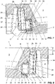
Figur 7 wird eine Schnittdarstellung durch den Ablaufkanal gezeigt. DieFigur 8 zeigt sodann eine Schnittdarstellung durch den Überlaufkanal. Die Überlaufkante liegt, wie in derFigur 8 gezeigt, in einem Abstand von 3 bis 6 Zentimeter von der Bezugsebene B. Der Abstand trägt das Bezugszeichen A. - Die
Figuren 9 und 10 zeigen sodann eine Frontansicht des Ablaufelements 6 und eine Schnittdarstellung. Von der Schnittdarstellung entlang der Schnittlinie X-X inFigur 9 wird ersichtlich, dass sich der Überlaufkanal 10 von der Überlaufeintrittsöffnung 9 mit einem ersten Kanalabschnitt 37 erstreckt. Dem ersten Kanalabschnitt 37 schliesst sich ein Steigabschnitt 38 an. Der Steigabschnitt 38 führt zur Überlaufkante 11. Nach der Überlaufkante 11 schliesst sich dem Steigabschnitt 38 ein Fallabschnitt 39 an. Der Fallabschnitt 39 mündet dann an der Mündungsstelle 36 in den Ablaufkanal 14. Der Steigabschnitt 38 und der Fallabschnitt 39 verlaufen hier parallel zueinander und sind, wie bereits erwähnt durch die Trennwand 26 voneinander getrennt. - Von der
Figur 10 wird weiter ersichtlich, dass in der gezeigten Ausführungsform der Ablaufkanal 12 einen Umlenkabschnitt 40 aufweist, welcher den Ablaufkanal in Richtung Überlaufkanal 20 umlenkt. Durch diesen Umlenkabschnitt 40 kann die Mündungsstelle 36 hinter einem geschlossenen Wandabschnitt der Wandstruktur 8 platziert werden. -
1 Waschtischanordnung 27 Innenraum 2 Waschtisch 28 Deckel 3 Wasserbecken 29 Innenseite 4 Hohlraum 30 Lagerwandung 5 Ablaufdurchgang 31 Befestigungsöffnungen 6 Ablaufelement 32 Dichtungselement 7 Rückwand 33 Seitenwand 8 Wandstruktur 36 Mündungsstelle 9 Überlaufeintrittsöffnung 37 erster Kanalabschnitt 10 Überlaufkanal 38 Steigabschnitt 11 Überlaufkante 39 Fallabschnitt 12 Ablauföffnung 40 Umlenkabschnitt 13 Sperrventil A Abstand 14 Ablaufkanal B Bezugsebene 15 Rand H Horizontale 16 Bodenwand F Fliessrichtung 17 Wandbereich 18 äussere Oberfläche 19 Durchgangsöffnung 20 gemeinsamer Kanal 21 Ablaufstutzen 22 untere Kante 23 untere Wandung 24 untere Kante 25 Wandung 26 Trennwand
Claims (17)
- Waschtischanordnung (1) umfassend
einen Waschtisch (2) mit einem Wasserbecken (3), einem Hohlraum (4) und einem Ablaufdurchgang (5), der sich vom Wasserbecken (3) in den Hohlraum (4) erstreckt, und
ein im Hohlraum (4) angeordnetes Ablaufelement (6) zum Wegführen von Wasser aus dem Ablaufdurchgang (5) und zum Zuführen des Wassers in eine Ablaufleitung,
wobei der Waschtisch (2) eine Rückwand (7) aufweist, mit welcher der Waschtisch (2) in Einbaulage mit einer gebäudeseitigen Anschlussstruktur in Kontakt bringbar ist, wobei der Hohlraum (4) im Bereich einer Rückwand (7) des Waschtisches (2) offen ausgebildet ist, und
wobei das Ablaufelement (6) eine Wandstruktur (8) aufweist, welche sich über den Querschnitt des Ablaufdurchgangs (5) erstreckt,
dadurch gekennzeichnet,
dass an der Wandstruktur (8) eine Überlaufeintrittsöffnung (9), der sich ein Überlaufkanal (10) mit einer Überlaufkante (11) anschliesst, und eine Ablauföffnung (12), der sich ein mit einem Sperrventil (13) öffnenbaren und verschliessbaren Ablaufkanal (14) anschliesst, angeordnet ist. - Waschtischanordnung (1) umfassend
einen Waschtisch (2) mit einem Wasserbecken (3), einem Hohlraum (4) und einem Ablaufdurchgang (5), der sich vom Wasserbecken (3) in den Hohlraum (4) erstreckt, und
ein im Hohlraum (4) angeordnetes Ablaufelement (6) zum Wegführen von Wasser aus dem Ablaufdurchgang (5) und zum Zuführen des Wassers in eine Ablaufleitung,
wobei der Waschtisch (2) eine Rückwand (7) aufweist, mit welcher der Waschtisch (2) in Einbaulage mit einer gebäudeseitigen Anschlussstruktur in Kontakt bringbar ist, wobei der Hohlraum (4) im Bereich einer Rückwand (7) des Waschtisches (2) offen ausgebildet ist, dadurch gekennzeichnet, dass das Ablaufelement (3) einen Überlaufkanal (10) mit einer Überlaufkante (11) aufweist, wobei sowohl der Überlaufkanal (10) als auch die Überlaufkante (11) im besagten Hohlraum (4) liegen. - Waschtischanordnung (1) nach Anspruch 2, dadurch gekennzeichnet, dass das Ablaufelement (6) eine Wandstruktur (8) aufweist, welche sich über den Querschnitt des Ablaufdurchgangs (5) erstreckt, wobei in der Wandstruktur (8) eine Überlaufeintrittsöffnung (9) angeordnet ist, welcher sich der Überlaufkanal (10) mit der Überlaufkante (11) anschliesst, und wobei in der Wandstruktur (8) eine Ablauföffnung (12), der sich ein mit einem Sperrventil (13) öffnenbaren und verschliessbaren Ablaufkanal (14) anschliesst.
- Waschtischanordnung (1) nach einem der vorhergehenden Ansprüche, dadurch gekennzeichnet, dass sich der Überlaufkanal (10) in Einbaulage im Hohlraum (4) nach oben hin erstreckt; und/oder dass der Überlaufkanal (10) vollständig im Hohlraum (4) liegt.
- Waschtischanordnung (1) nach einem der vorhergehenden Ansprüche, dadurch gekennzeichnet, dass der Ablaufdurchgang (5) aus dem Wasserbecken (3) an einer Seitenwand (33) des Wasserbeckens (3) angeordnet ist und sich vom Wasserbecken (3) in Einbaulage gesehen im Wesentlichen nach hinten weg erstreckt.
- Waschtischanordnung (1) nach einem der vorhergehenden Ansprüche, dadurch gekennzeichnet, dass das Sperrventil (13) entweder im Hohlraum (4) oder im Ablaufdurchgang (5) liegt.
- Waschtischanordnung (1) nach einem der vorhergehenden Ansprüche, dadurch gekennzeichnet, dass das Wasserbecken (3) durch einen oberen in Einbaulage in der Horizontalen (H) liegenden Rand (15) begrenzt ist, wobei der Rand (15) eine Bezugsebene (B) aufspannt und wobei die Überlaufkante (11) in einem rechtwinklig zur Bezugsebene gesehenem Abstand (A) von 3 bis 6 Zentimeter von der Bezugsebene (B) entfernt ist.
- Waschtischanordnung (1) nach einem der vorhergehenden Ansprüche, dadurch gekennzeichnet, dass das Ablaufelement (6) im Wesentlichen vollständig im Hohlraum (4) liegt und erstreckt sich vom Hohlraum (4) in den Ablaufdurchgang hinein.
- Waschtischanordnung (1) nach einem der vorhergehenden Ansprüche, dadurch gekennzeichnet, dass der Waschtisch (2) weiterhin eine Bodenwand (16) aufweist, wobei die Bodenwand (16) im Bereich des Hohlraums (4) in Einbaulage nach unten offen ausgebildet ist, und wobei das Ablaufelement (6) nicht über eine durch die Bodenwand (16) aufgespannte Ebene nach unten ragt.
- Waschtischanordnung (1) nach Anspruch 9, dadurch gekennzeichnet, dass sich der Überlaufkanal (10) in Einbaulage gesehen ausschliesslich oberhalb der besagten durch die Bodenwand (16) aufgespannten Ebene erstreckt.
- Waschtischanordnung (1) nach einem der vorhergehenden Ansprüche, dadurch gekennzeichnet, dass der Hohlraum (4) nach oben hin durch einen Wandbereich (17) des Waschtischs (2) begrenzt ist, welcher Wandbereich (17) eine äussere Oberfläche (18) aufweist,
wobei die Überlaufkante (11) höchstens 3 bis 6 Zentimeter von der äusseren Oberfläche (18) entfernt liegt; und/oder
wobei der Wandbereich (17) eine Durchgangsöffnung (19) zur Durchführung einer Zuleitung zu einer Wasserauslaufarmatur und/oder zur Durchführung einer Sperrventilbetätigungsstange aufweist. - Waschtischanordnung (1) nach einem der vorhergehenden Ansprüche, dadurch gekennzeichnet, dass der Überlaufkanal (10) und der Ablaufkanal (14) ineinander münden und sich als gemeinsamer Kanal (20) zu einem Ablaufstutzen (21) fortsetzen, wobei die Mündungsstelle vom Überlaufkanal (10) und vom Ablaufkanal (14) im besagten Hohlraum (4) liegt.
- Waschtischanordnung (1) nach Anspruch 12, dadurch gekennzeichnet, dass der Ablaufstutzen derart angeordnet ist, dass dieser eine durch die Rückwand (7) aufgespannte Ebene nicht durchdringt.
- Waschtischanordnung (1) nach einem der vorhergehenden Ansprüche, dadurch gekennzeichnet, dass das Sperrventil (13) in Fliessrichtung des Wassers gesehen vor der Ablauföffnung (12) oder im Ablaufkanal (14) liegt.
- Waschtischanordnung (1) nach einem der vorhergehenden Ansprüche, dadurch gekennzeichnet,
dass die Ablauföffnung (12) vom Ablaufdurchgang (5) gesehen mittig in der Wandstruktur (8) und mit einer unteren Kante (22) auf Höhe oder unterhalb einer unteren Wandung (23) des Ablaufdurchgangs (5) zu liegen kommt; und/oder
dass die Überlaufeintrittsöffnung (9) seitlich neben der Ablauföffnung (12) liegt und mit einer unteren Kante (24) auf Höhe oder unterhalb einer unteren Wandung (23) des Ablaufdurchgangs zu liegen kommt. - Waschtischanordnung (1) nach einem der vorhergehenden Ansprüche, dadurch gekennzeichnet, dass der Überlaufkanal (10) durch eine Wandung (25) seitlich umgeben ist, wobei sich die Wandung (25) vorzugsweise über die Wandstruktur (8) nach oben erstreckt und dass sich eine Trennwand (26) mit der Überlaufkante (11) quer durch den durch die Wandung (25) begrenzten Innenraum (27) erstreckt.
- Waschtischanordnung (1) nach einem der vorhergehenden Ansprüche, dadurch gekennzeichnet, dass der Überlaufkanal (10) nach oben hin mit einem Deckel (28) verschlossen ist, wobei die Innenseite (29) des Deckels (28) in einem Abstand zur Überlaufkante (11) steht.
Priority Applications (6)
| Application Number | Priority Date | Filing Date | Title |
|---|---|---|---|
| EP21164564.3A EP4063576B1 (de) | 2021-03-24 | 2021-03-24 | Waschtischanordnung |
| EP24211819.8A EP4481125A3 (de) | 2021-03-24 | 2021-03-24 | Waschtischanordnung |
| PL21164564.3T PL4063576T3 (pl) | 2021-03-24 | 2021-03-24 | Układ umywalkowy |
| CN202210285900.XA CN115126051A (zh) | 2021-03-24 | 2022-03-22 | 盥洗台装置 |
| CN202210292387.7A CN115126053A (zh) | 2021-03-24 | 2022-03-23 | 盥洗台装置 |
| CN202210294275.5A CN115126052B (zh) | 2021-03-24 | 2022-03-23 | 盥洗台装置 |
Applications Claiming Priority (1)
| Application Number | Priority Date | Filing Date | Title |
|---|---|---|---|
| EP21164564.3A EP4063576B1 (de) | 2021-03-24 | 2021-03-24 | Waschtischanordnung |
Related Child Applications (2)
| Application Number | Title | Priority Date | Filing Date |
|---|---|---|---|
| EP24211819.8A Division-Into EP4481125A3 (de) | 2021-03-24 | 2021-03-24 | Waschtischanordnung |
| EP24211819.8A Division EP4481125A3 (de) | 2021-03-24 | 2021-03-24 | Waschtischanordnung |
Publications (2)
| Publication Number | Publication Date |
|---|---|
| EP4063576A1 true EP4063576A1 (de) | 2022-09-28 |
| EP4063576B1 EP4063576B1 (de) | 2025-05-21 |
Family
ID=75203186
Family Applications (2)
| Application Number | Title | Priority Date | Filing Date |
|---|---|---|---|
| EP21164564.3A Active EP4063576B1 (de) | 2021-03-24 | 2021-03-24 | Waschtischanordnung |
| EP24211819.8A Pending EP4481125A3 (de) | 2021-03-24 | 2021-03-24 | Waschtischanordnung |
Family Applications After (1)
| Application Number | Title | Priority Date | Filing Date |
|---|---|---|---|
| EP24211819.8A Pending EP4481125A3 (de) | 2021-03-24 | 2021-03-24 | Waschtischanordnung |
Country Status (2)
| Country | Link |
|---|---|
| EP (2) | EP4063576B1 (de) |
| PL (1) | PL4063576T3 (de) |
Citations (9)
| Publication number | Priority date | Publication date | Assignee | Title |
|---|---|---|---|---|
| US4969217A (en) * | 1988-05-16 | 1990-11-13 | American Standard Inc. | Drain assembly for sanitary fixture with built-in overflow device |
| US5625909A (en) * | 1994-02-09 | 1997-05-06 | Ericson; Kurt S. B. | Sanitary appliance with indirect discharge |
| EP1754838A2 (de) | 2005-07-27 | 2007-02-21 | Valpra by Rossi S.r.l. | Ablauf mit seitlichem Einlass |
| DE202008008557U1 (de) | 2008-06-25 | 2008-10-02 | Listringhaus, Volker | Waschtisch oder Bidet mit waagerechtem Ablaufaustritt, sowie Durchbruch in der Rückwand zur Aufnahme einer Anschlussarmatur |
| US20090260154A1 (en) * | 2008-04-22 | 2009-10-22 | Shoop Douglas M | Tub drain and overflow assembly |
| DE102008044637A1 (de) | 2008-04-15 | 2009-10-22 | Hewi Heinrich Wilke Gmbh | Waschtisch |
| WO2019185812A1 (de) * | 2018-03-29 | 2019-10-03 | Geberit International Ag | Waschtisch |
| WO2019185810A1 (de) * | 2018-03-29 | 2019-10-03 | Geberit International Ag | Ablaufanordnung für einen waschtisch |
| US20200217054A1 (en) * | 2017-10-25 | 2020-07-09 | Kaihua Chen | A sink having an invisible drainage device |
Family Cites Families (2)
| Publication number | Priority date | Publication date | Assignee | Title |
|---|---|---|---|---|
| AU5274079A (en) * | 1978-11-12 | 1980-06-12 | Politi, S. | Sanitary fixture |
| CN111970945B (zh) * | 2018-03-29 | 2022-02-22 | 吉博力国际股份公司 | 盥洗台 |
-
2021
- 2021-03-24 EP EP21164564.3A patent/EP4063576B1/de active Active
- 2021-03-24 EP EP24211819.8A patent/EP4481125A3/de active Pending
- 2021-03-24 PL PL21164564.3T patent/PL4063576T3/pl unknown
Patent Citations (9)
| Publication number | Priority date | Publication date | Assignee | Title |
|---|---|---|---|---|
| US4969217A (en) * | 1988-05-16 | 1990-11-13 | American Standard Inc. | Drain assembly for sanitary fixture with built-in overflow device |
| US5625909A (en) * | 1994-02-09 | 1997-05-06 | Ericson; Kurt S. B. | Sanitary appliance with indirect discharge |
| EP1754838A2 (de) | 2005-07-27 | 2007-02-21 | Valpra by Rossi S.r.l. | Ablauf mit seitlichem Einlass |
| DE102008044637A1 (de) | 2008-04-15 | 2009-10-22 | Hewi Heinrich Wilke Gmbh | Waschtisch |
| US20090260154A1 (en) * | 2008-04-22 | 2009-10-22 | Shoop Douglas M | Tub drain and overflow assembly |
| DE202008008557U1 (de) | 2008-06-25 | 2008-10-02 | Listringhaus, Volker | Waschtisch oder Bidet mit waagerechtem Ablaufaustritt, sowie Durchbruch in der Rückwand zur Aufnahme einer Anschlussarmatur |
| US20200217054A1 (en) * | 2017-10-25 | 2020-07-09 | Kaihua Chen | A sink having an invisible drainage device |
| WO2019185812A1 (de) * | 2018-03-29 | 2019-10-03 | Geberit International Ag | Waschtisch |
| WO2019185810A1 (de) * | 2018-03-29 | 2019-10-03 | Geberit International Ag | Ablaufanordnung für einen waschtisch |
Also Published As
| Publication number | Publication date |
|---|---|
| EP4063576B1 (de) | 2025-05-21 |
| EP4481125A3 (de) | 2025-04-30 |
| PL4063576T3 (pl) | 2025-09-15 |
| EP4481125A2 (de) | 2024-12-25 |
Similar Documents
| Publication | Publication Date | Title |
|---|---|---|
| EP3773098B1 (de) | Waschtisch | |
| EP2540923B1 (de) | Abwasserablauf mit Geruchsverschluss | |
| EP2236683B1 (de) | Duschrinnenanordnung für Wandeinbau | |
| EP2808458B1 (de) | Wasserablaufvorrichtung für eine Dusche und Duschbodenelement | |
| EP3910118B1 (de) | Ablaufanordnung | |
| DE202008001013U1 (de) | Ablaufarmatur, insbesondere für Dusch- oder Badewannen | |
| EP1862602B1 (de) | Becken mit verdecktem Überlauf und zugehöriger Ablaufgarnitur | |
| DE3918321C2 (de) | Ablauf mit einem Wassergeruchsverschlußeinsatz | |
| EP4063576B1 (de) | Waschtischanordnung | |
| DE10360310A1 (de) | Ablaufvorrichtung | |
| EP4063574B1 (de) | Waschtischanordnung | |
| EP3825479A1 (de) | Spülwasserverteiler | |
| EP4063575A1 (de) | Waschtischanordnung | |
| EP3775415B1 (de) | Ablaufanordnung für einen waschtisch | |
| EP3680405B1 (de) | Einbaukasten | |
| EP0916775B1 (de) | Kastenkörper für einen Spülkasten | |
| EP3647504B1 (de) | Sanitärartikelanordnung | |
| EP4071312B1 (de) | Vorrichtung für eine im boden eines raumes angeordnete ablaufvorrichtung sowie ablaufvorrichtung mit einer derartigen vorrichtung | |
| DE102004011853A1 (de) | Ablaufvorrichtung für eine Dusche oder dergleichen | |
| EP1921217A2 (de) | Klosett | |
| EP3569777B1 (de) | Sanitäres tragsystem | |
| DE29613379U1 (de) | Spüle, insbesondere Einbauspüle | |
| EP1561868A2 (de) | Ablaufvorrichtung für eine Duschwanne | |
| CH716366B1 (de) | Spülwasserverteiler für einen Sanitärartikel. | |
| DE10204683A1 (de) | Becken |
Legal Events
| Date | Code | Title | Description |
|---|---|---|---|
| PUAI | Public reference made under article 153(3) epc to a published international application that has entered the european phase |
Free format text: ORIGINAL CODE: 0009012 |
|
| STAA | Information on the status of an ep patent application or granted ep patent |
Free format text: STATUS: THE APPLICATION HAS BEEN PUBLISHED |
|
| AK | Designated contracting states |
Kind code of ref document: A1 Designated state(s): AL AT BE BG CH CY CZ DE DK EE ES FI FR GB GR HR HU IE IS IT LI LT LU LV MC MK MT NL NO PL PT RO RS SE SI SK SM TR |
|
| STAA | Information on the status of an ep patent application or granted ep patent |
Free format text: STATUS: REQUEST FOR EXAMINATION WAS MADE |
|
| 17P | Request for examination filed |
Effective date: 20230125 |
|
| RBV | Designated contracting states (corrected) |
Designated state(s): AL AT BE BG CH CY CZ DE DK EE ES FI FR GB GR HR HU IE IS IT LI LT LU LV MC MK MT NL NO PL PT RO RS SE SI SK SM TR |
|
| RAP1 | Party data changed (applicant data changed or rights of an application transferred) |
Owner name: GEBERIT INTERNATIONAL AG |
|
| GRAP | Despatch of communication of intention to grant a patent |
Free format text: ORIGINAL CODE: EPIDOSNIGR1 |
|
| STAA | Information on the status of an ep patent application or granted ep patent |
Free format text: STATUS: GRANT OF PATENT IS INTENDED |
|
| INTG | Intention to grant announced |
Effective date: 20241002 |
|
| P01 | Opt-out of the competence of the unified patent court (upc) registered |
Free format text: CASE NUMBER: APP_60197/2024 Effective date: 20241108 |
|
| GRAJ | Information related to disapproval of communication of intention to grant by the applicant or resumption of examination proceedings by the epo deleted |
Free format text: ORIGINAL CODE: EPIDOSDIGR1 |
|
| STAA | Information on the status of an ep patent application or granted ep patent |
Free format text: STATUS: REQUEST FOR EXAMINATION WAS MADE |
|
| GRAP | Despatch of communication of intention to grant a patent |
Free format text: ORIGINAL CODE: EPIDOSNIGR1 |
|
| STAA | Information on the status of an ep patent application or granted ep patent |
Free format text: STATUS: GRANT OF PATENT IS INTENDED |
|
| INTC | Intention to grant announced (deleted) | ||
| INTG | Intention to grant announced |
Effective date: 20250217 |
|
| GRAJ | Information related to disapproval of communication of intention to grant by the applicant or resumption of examination proceedings by the epo deleted |
Free format text: ORIGINAL CODE: EPIDOSDIGR1 |
|
| STAA | Information on the status of an ep patent application or granted ep patent |
Free format text: STATUS: REQUEST FOR EXAMINATION WAS MADE |
|
| GRAP | Despatch of communication of intention to grant a patent |
Free format text: ORIGINAL CODE: EPIDOSNIGR1 |
|
| STAA | Information on the status of an ep patent application or granted ep patent |
Free format text: STATUS: GRANT OF PATENT IS INTENDED |
|
| GRAS | Grant fee paid |
Free format text: ORIGINAL CODE: EPIDOSNIGR3 |
|
| GRAA | (expected) grant |
Free format text: ORIGINAL CODE: 0009210 |
|
| STAA | Information on the status of an ep patent application or granted ep patent |
Free format text: STATUS: THE PATENT HAS BEEN GRANTED |
|
| INTC | Intention to grant announced (deleted) | ||
| INTG | Intention to grant announced |
Effective date: 20250404 |
|
| AK | Designated contracting states |
Kind code of ref document: B1 Designated state(s): AL AT BE BG CH CY CZ DE DK EE ES FI FR GB GR HR HU IE IS IT LI LT LU LV MC MK MT NL NO PL PT RO RS SE SI SK SM TR |
|
| REG | Reference to a national code |
Ref country code: GB Ref legal event code: FG4D Free format text: NOT ENGLISH |
|
| REG | Reference to a national code |
Ref country code: CH Ref legal event code: EP |
|
| REG | Reference to a national code |
Ref country code: DE Ref legal event code: R096 Ref document number: 502021007505 Country of ref document: DE |
|
| REG | Reference to a national code |
Ref country code: IE Ref legal event code: FG4D Free format text: LANGUAGE OF EP DOCUMENT: GERMAN |
|
| REG | Reference to a national code |
Ref country code: SE Ref legal event code: TRGR |
|
| REG | Reference to a national code |
Ref country code: NL Ref legal event code: MP Effective date: 20250521 |
|
| PG25 | Lapsed in a contracting state [announced via postgrant information from national office to epo] |
Ref country code: PT Free format text: LAPSE BECAUSE OF FAILURE TO SUBMIT A TRANSLATION OF THE DESCRIPTION OR TO PAY THE FEE WITHIN THE PRESCRIBED TIME-LIMIT Effective date: 20250922 Ref country code: FI Free format text: LAPSE BECAUSE OF FAILURE TO SUBMIT A TRANSLATION OF THE DESCRIPTION OR TO PAY THE FEE WITHIN THE PRESCRIBED TIME-LIMIT Effective date: 20250521 Ref country code: ES Free format text: LAPSE BECAUSE OF FAILURE TO SUBMIT A TRANSLATION OF THE DESCRIPTION OR TO PAY THE FEE WITHIN THE PRESCRIBED TIME-LIMIT Effective date: 20250521 |
|
| REG | Reference to a national code |
Ref country code: LT Ref legal event code: MG9D |
|
| PG25 | Lapsed in a contracting state [announced via postgrant information from national office to epo] |
Ref country code: GR Free format text: LAPSE BECAUSE OF FAILURE TO SUBMIT A TRANSLATION OF THE DESCRIPTION OR TO PAY THE FEE WITHIN THE PRESCRIBED TIME-LIMIT Effective date: 20250822 Ref country code: NO Free format text: LAPSE BECAUSE OF FAILURE TO SUBMIT A TRANSLATION OF THE DESCRIPTION OR TO PAY THE FEE WITHIN THE PRESCRIBED TIME-LIMIT Effective date: 20250821 |
|
| PG25 | Lapsed in a contracting state [announced via postgrant information from national office to epo] |
Ref country code: NL Free format text: LAPSE BECAUSE OF FAILURE TO SUBMIT A TRANSLATION OF THE DESCRIPTION OR TO PAY THE FEE WITHIN THE PRESCRIBED TIME-LIMIT Effective date: 20250521 |
|
| PG25 | Lapsed in a contracting state [announced via postgrant information from national office to epo] |
Ref country code: BG Free format text: LAPSE BECAUSE OF FAILURE TO SUBMIT A TRANSLATION OF THE DESCRIPTION OR TO PAY THE FEE WITHIN THE PRESCRIBED TIME-LIMIT Effective date: 20250521 |
|
| PG25 | Lapsed in a contracting state [announced via postgrant information from national office to epo] |
Ref country code: HR Free format text: LAPSE BECAUSE OF FAILURE TO SUBMIT A TRANSLATION OF THE DESCRIPTION OR TO PAY THE FEE WITHIN THE PRESCRIBED TIME-LIMIT Effective date: 20250521 |
|
| PG25 | Lapsed in a contracting state [announced via postgrant information from national office to epo] |
Ref country code: RS Free format text: LAPSE BECAUSE OF FAILURE TO SUBMIT A TRANSLATION OF THE DESCRIPTION OR TO PAY THE FEE WITHIN THE PRESCRIBED TIME-LIMIT Effective date: 20250821 |
|
| PG25 | Lapsed in a contracting state [announced via postgrant information from national office to epo] |
Ref country code: IS Free format text: LAPSE BECAUSE OF FAILURE TO SUBMIT A TRANSLATION OF THE DESCRIPTION OR TO PAY THE FEE WITHIN THE PRESCRIBED TIME-LIMIT Effective date: 20250921 |
|
| PG25 | Lapsed in a contracting state [announced via postgrant information from national office to epo] |
Ref country code: LV Free format text: LAPSE BECAUSE OF FAILURE TO SUBMIT A TRANSLATION OF THE DESCRIPTION OR TO PAY THE FEE WITHIN THE PRESCRIBED TIME-LIMIT Effective date: 20250521 |
|
| PG25 | Lapsed in a contracting state [announced via postgrant information from national office to epo] |
Ref country code: SM Free format text: LAPSE BECAUSE OF FAILURE TO SUBMIT A TRANSLATION OF THE DESCRIPTION OR TO PAY THE FEE WITHIN THE PRESCRIBED TIME-LIMIT Effective date: 20250521 Ref country code: DK Free format text: LAPSE BECAUSE OF FAILURE TO SUBMIT A TRANSLATION OF THE DESCRIPTION OR TO PAY THE FEE WITHIN THE PRESCRIBED TIME-LIMIT Effective date: 20250521 |
|
| PG25 | Lapsed in a contracting state [announced via postgrant information from national office to epo] |
Ref country code: CZ Free format text: LAPSE BECAUSE OF FAILURE TO SUBMIT A TRANSLATION OF THE DESCRIPTION OR TO PAY THE FEE WITHIN THE PRESCRIBED TIME-LIMIT Effective date: 20250521 |
|
| PG25 | Lapsed in a contracting state [announced via postgrant information from national office to epo] |
Ref country code: EE Free format text: LAPSE BECAUSE OF FAILURE TO SUBMIT A TRANSLATION OF THE DESCRIPTION OR TO PAY THE FEE WITHIN THE PRESCRIBED TIME-LIMIT Effective date: 20250521 |
|
| PG25 | Lapsed in a contracting state [announced via postgrant information from national office to epo] |
Ref country code: SK Free format text: LAPSE BECAUSE OF FAILURE TO SUBMIT A TRANSLATION OF THE DESCRIPTION OR TO PAY THE FEE WITHIN THE PRESCRIBED TIME-LIMIT Effective date: 20250521 |
|
| REG | Reference to a national code |
Ref country code: DE Ref legal event code: R097 Ref document number: 502021007505 Country of ref document: DE |
|
| PLBE | No opposition filed within time limit |
Free format text: ORIGINAL CODE: 0009261 |
|
| STAA | Information on the status of an ep patent application or granted ep patent |
Free format text: STATUS: NO OPPOSITION FILED WITHIN TIME LIMIT |
|
| REG | Reference to a national code |
Ref country code: CH Ref legal event code: U11 Free format text: ST27 STATUS EVENT CODE: U-0-0-U10-U11 (AS PROVIDED BY THE NATIONAL OFFICE) Effective date: 20260401 |
|
| REG | Reference to a national code |
Ref country code: CH Ref legal event code: L10 Free format text: ST27 STATUS EVENT CODE: U-0-0-L10-L00 (AS PROVIDED BY THE NATIONAL OFFICE) Effective date: 20260402 |
|
| PGFP | Annual fee paid to national office [announced via postgrant information from national office to epo] |
Ref country code: SE Payment date: 20260319 Year of fee payment: 6 |
|
| PGFP | Annual fee paid to national office [announced via postgrant information from national office to epo] |
Ref country code: GB Payment date: 20260324 Year of fee payment: 6 |
|
| PGFP | Annual fee paid to national office [announced via postgrant information from national office to epo] |
Ref country code: DE Payment date: 20260319 Year of fee payment: 6 |
|
| PGFP | Annual fee paid to national office [announced via postgrant information from national office to epo] |
Ref country code: AT Payment date: 20260320 Year of fee payment: 6 |
|
| PGFP | Annual fee paid to national office [announced via postgrant information from national office to epo] |
Ref country code: IT Payment date: 20260319 Year of fee payment: 6 |
|
| PGFP | Annual fee paid to national office [announced via postgrant information from national office to epo] |
Ref country code: FR Payment date: 20260323 Year of fee payment: 6 |
|
| PGFP | Annual fee paid to national office [announced via postgrant information from national office to epo] |
Ref country code: PL Payment date: 20260303 Year of fee payment: 6 |
|
| 26N | No opposition filed |
Effective date: 20260224 |