EP4063542A2 - Yarn spinning system - Google Patents
Yarn spinning system Download PDFInfo
- Publication number
- EP4063542A2 EP4063542A2 EP22160455.6A EP22160455A EP4063542A2 EP 4063542 A2 EP4063542 A2 EP 4063542A2 EP 22160455 A EP22160455 A EP 22160455A EP 4063542 A2 EP4063542 A2 EP 4063542A2
- Authority
- EP
- European Patent Office
- Prior art keywords
- cooling
- down direction
- block member
- spinning system
- bolt
- Prior art date
- Legal status (The legal status is an assumption and is not a legal conclusion. Google has not performed a legal analysis and makes no representation as to the accuracy of the status listed.)
- Granted
Links
Images





Classifications
-
- D—TEXTILES; PAPER
- D01—NATURAL OR MAN-MADE THREADS OR FIBRES; SPINNING
- D01D—MECHANICAL METHODS OR APPARATUS IN THE MANUFACTURE OF ARTIFICIAL FILAMENTS, THREADS, FIBRES, BRISTLES OR RIBBONS
- D01D5/00—Formation of filaments, threads, or the like
- D01D5/08—Melt spinning methods
- D01D5/088—Cooling filaments, threads or the like, leaving the spinnerettes
- D01D5/092—Cooling filaments, threads or the like, leaving the spinnerettes in shafts or chimneys
-
- D—TEXTILES; PAPER
- D01—NATURAL OR MAN-MADE THREADS OR FIBRES; SPINNING
- D01D—MECHANICAL METHODS OR APPARATUS IN THE MANUFACTURE OF ARTIFICIAL FILAMENTS, THREADS, FIBRES, BRISTLES OR RIBBONS
- D01D13/00—Complete machines for producing artificial threads
- D01D13/02—Elements of machines in combination
-
- D—TEXTILES; PAPER
- D01—NATURAL OR MAN-MADE THREADS OR FIBRES; SPINNING
- D01D—MECHANICAL METHODS OR APPARATUS IN THE MANUFACTURE OF ARTIFICIAL FILAMENTS, THREADS, FIBRES, BRISTLES OR RIBBONS
- D01D5/00—Formation of filaments, threads, or the like
- D01D5/08—Melt spinning methods
- D01D5/088—Cooling filaments, threads or the like, leaving the spinnerettes
Definitions
- the present invention relates to a yarn spinning system.
- Patent Literature 1 Japanese Laid-Open Patent Publication No. 2016-108698 discloses a yarn spinning system configured to generate yarns made of synthetic fibers.
- the yarn spinning system includes a spinning apparatus configured to discharge (spin out), through a spinneret, hot molten polymer that is a yarn material and a cooling apparatus provided below the spinning apparatus.
- the spinning apparatus has plural spinnerets.
- the yarn material discharged from each of the spinnerets is cooled by the cooling apparatus and solidified, and becomes a yarn formed of one or more filament. In other words, yarns that are identical in number with the spinnerets are generated.
- a space in which the yarn material discharged from the spinnerets and descend are slowly cooled is formed between the spinning apparatus and the cooling apparatus.
- An appropriate length in the up-down direction of the slow cooling space i.e., an appropriate distance between the spinnerets and the cooling apparatus in the up-down direction
- yarn type the type of the yarn material
- the thickness of each filament the number of filaments, and so forth.
- the length (spinneret surface depth in Patent Literature 1) in the up-down direction of the slow cooling space may need to be changed.
- Patent Literature 1 recites a spinneret surface depth variable device capable of changing the spinneret surface depth.
- the spinneret surface depth variable device includes a cylindrical upper hood fixed to the bottom surface of the spinning apparatus and a cylindrical lower hood fixed to the top surface of the cooling apparatus.
- the upper hood is arranged to surround at least an upper part of the lower hood.
- the cooling apparatus is arranged to be movable in the up-down direction. As the cooling apparatus and the lower hood move in the up-down direction, the spinneret surface depth is changed while preventing outside air from flowing into the slow cooling space.
- An object of the present invention is to allow a slow cooling space to be changed in length in the up-down direction when the number of yarns spun out is large, with a small number of members.
- a yarn spinning system includes: a spinning apparatus which includes spinnerets from which yarns are spun out, respectively; a cooling apparatus which is provided below the spinning apparatus and is configured to cool the yarns spun out from the respective spinnerets; and a slow cooling unit which is provided between the spinning apparatus and the cooling apparatus in an up-down direction, the cooling apparatus including cooling cylinders which extend in the up-down direction, surround the respective yarns, and are arranged to guide cooling wind to the yarns, and the slow cooling unit including: a block member which includes surrounding faces arranged to surround at least parts in the up-down direction of the respective cooling cylinders, the surrounding faces having parts above the cooling cylinders and the parts forming slow cooling spaces in which slow cooling of the yarns is performed; and an adjustment unit which is capable of adjusting relative positions of the block member and the cooling cylinders in the up-down direction.
- the distance in the up-down direction between the spinneret and the cooling apparatus i.e., the length in the up-down direction of the slow cooling space
- the distance in the up-down direction between the spinneret and the cooling apparatus can be changed by adjusting the relative positions in the up-down direction of the block member and the cooling cylinders by the adjustment unit. It is therefore possible to change the length of the slow cooling space in the up-down direction when the number of yarns that the yarn spinning system is able to spin out is large, with a small number of members.
- the yarn spinning system of the first aspect further includes a sealing member which is sandwiched between the spinning apparatus and the block member in the up-down direction.
- the yarn quality may be deteriorated.
- intrusion of outside air into the slow cooling space through a gap between the spinning apparatus and the block member can be reliably suppressed by the sealing member. It is therefore possible to suppress variations in temperature of the spinneret due to the outside air.
- the yarn spinning system of the second aspect is arranged so that the sealing member is a heat insulation member.
- the yarn spinning system of any one of the first to third aspects further includes a movement mechanism which is configured to move the cooling apparatus between a first position where the yarns are spun out from the spinning apparatus and a second position which is below the first position, when the cooling apparatus is at the second position, a working space being formed between the spinning apparatus and the cooling apparatus in the up-down direction to allow operations to be performed for the spinnerets, the cooling cylinders, and the adjustment unit.
- the cooling apparatus by moving the cooling apparatus to the second position, it is possible to perform operations for the spinnerets, the cooling cylinders, and the adjustment unit in the working space. Good workability is achieved for this reason.
- the yarn spinning system of the fourth aspect is arranged so that the block member is arranged to move together with the cooling apparatus when the movement mechanism is driven.
- the block member is arranged to move relative to the cooling apparatus when the cooling apparatus moves to the second position, the block member and the cooling cylinders would be temporarily separated.
- the cooling apparatus when the cooling apparatus is moved from the second position to the first position, it may be necessary to align the surrounding faces with the cooling cylinders. This may be time consuming.
- the cooling apparatus when the cooling apparatus is moved, the state in which the surrounding faces surround the respective cooling cylinders is maintained. It is therefore unnecessary to perform the above-described alignment.
- the yarn spinning system of the fifth aspect is arranged so that the adjustment unit includes at least one mounting portion which allows the block member to be mounted and is movable in the up-down direction relative to the cooling apparatus.
- the block member can be easily removed from the at least one mounting portion according to need.
- the yarn spinning system of the sixth aspect is arranged so that the adjustment unit includes at least one bolt which extends in the up-down direction and supports the at least one mounting portion, respectively, and the at least one mounting portion is moved in the up-down direction as the at least one bolt is rotated.
- the position in the up-down direction of the mounting portion can be finely adjusted by a simple structure using the bolt.
- the relative positions of the block member and the cooling cylinders can be finely adjusted by a simple structure.
- the yarn spinning system of the seventh aspect further includes a base portion with which the at least one bolt is screwed, when the at least one bolt is rotated, the at least one bolt being moved in the up-down direction relative to the base portion, and the at least one mounting portion being movable together with the respective at least one bolt in the up-down direction.
- This aspect of the invention makes it possible to move the at least one mounting portion in the up-down direction with a simple structure.
- the yarn spinning system of the eighth aspect is arranged so that the at least one mounting portion includes at least one nut on each of which a mounting surface making contact with the block member is formed, and the at least one nut is fixed to the at least one bolt, respectively.
- the at least one mounting portion can be formed by the at least one nut that is typically inexpensive. It is therefore possible to decrease the cost of the members.
- the yarn spinning system of any one of the seventh to ninth aspect is arranged so that the block member has at least one working hole which allows an operation for the at least one bolt to be performed while the block member is kept mounted on the at least one mounting portion.
- a tool for rotating the at least one bolt is inserted into the at least one working hole.
- the tool is able to access the at least one bolt.
- it is possible to rotate the at least one bolt while the block member is kept mounted on the at least one mounting portion. In other words, it is unnecessary to remove the block member from the at least one mounting portion when the at least one bolt is rotated. It is therefore possible to reduce the labor required for manually adjusting the relative positions of the block member and the cooling cylinders.
- the yarn spinning system of any one of the sixth to tenth aspects is arranged so that the adjustment unit includes plural mounting portions as the at least one mounting portion.
- the block member When only one mounting portion is provided, the block member may become imbalanced and slightly tilt relative to the horizontal direction, depending on the relationship in size between the mounting portion and the block member. In such a case, for example, the block member may make contact with the cooling cylinders, and an operation to adjust the relative positions of the block member and the cooling cylinders may be obstructed.
- the block member is mounted on the plural mounting portions. This makes it possible to maintain the balance of the block member in a suitable manner.
- each of the cooling cylinders includes: a filter member which is attachable to and detachable from the cooling apparatus; and a pressing member which is arranged to press the filter member from above, and when the cooling apparatus is at the second position, the pressing member is switchable between a pressing state in which the pressing member presses the filter member from above and a detached state in which the pressing state is canceled and the filter member is allowed to be lifted up.
- the filter member and the cooling apparatus are movable together, it may be necessary to move the block member relative to the cooling apparatus when the filter member is detached from the cooling apparatus, depending on the positional relationship between the pressing member and the block member.
- the filter member can be lifted up and detached from the cooling apparatus without moving the block member relative to the cooling apparatus.
- the yarn spinning system of the twelfth aspect is arranged so that the pressing member is a ring member which is attachable to and detachable from a top surface of each of the cooling cylinders.
- the filter member can be pressed from above by the pressing member that is structurally simple, and the filter member can be detached from the cooling apparatus.
- the yarn spinning system of any one of the first to thirteenth aspects is arranged so that the cooling cylinders include extension portions extending downward as compared to a bottom surface of the block member, respectively, and at least one covering member is provided to be movable at least in the up-down direction relative to the extension portions and to cover gaps between the cooling cylinders and the surrounding faces.
- the gap between the surrounding face of the block member and the outer circumferential surface of the cooling cylinder is wide, outside air tends to enter the slow cooling space, and the yarn quality may be deteriorated.
- the gap is preferably as narrow as possible.
- the surrounding face of the block member tends to make contact with the outer circumferential surface of the cooling cylinder when the relative positions of the block member and the cooling cylinders is adjusted in the up-down direction. This may prevent the relative movement of the block member and the cooling cylinders, and the adjustment may become difficult.
- the present invention when the yarns are produced, the gap between the surrounding face of the block member and the outer circumferential surface of the cooling cylinder is covered with the covering member. On this account, even when the gap is wide, intrusion of the outside air into the slow cooling space is prevented. Easiness of the positional adjustment of the block member and good yarn quality are both achieved with this arrangement.
- the yarn spinning system of the fourteenth aspect is arranged so that the at least one covering member is attachable to and detachable from the extension portions.
- the covering member does not obstruct the adjustment of the relative positions of the surrounding face of the block member and the cooling cylinder.
- the up-down direction (the up-down direction in the plane of FIG. 1 ) is a vertical direction in which the gravity acts.
- the front-rear direction (the left-right direction in the plane of FIG. 1 ) is a direction orthogonal to the up-down direction.
- a direction orthogonal to both the up-down direction and the front-rear direction (i.e., a direction perpendicular to the plane of FIG. 1 ) is set as a left-right direction.
- the yarn spinning system 1 is a system configured to generate yarns Y formed of synthetic fibers.
- the yarn spinning system 1 includes a spinning apparatus 2, a cooling apparatus 3, a slow cooling unit 4, and an oil applicator 5.
- the spinning apparatus 2 is a melt spinning device configured to spin out yarns Y made of molten polymer.
- the spinning apparatus 2 includes a frame 10 that is substantially rectangular parallelepiped in shape, pack housings 11 formed in the frame 10, and spinning packs 12 attached to the respective pack housings 11.
- the spinning packs 12 are, for example, staggered to form two lines along the left-right direction. (The packs are not illustrated. As to the arrangement in the horizontal direction, see, e.g., cooling cylinders 21 and first through holes 31 described below and shown in FIG. 4 .)
- To each spinning pack 12 hot liquid molten polymer (yarn material) is supplied from an unillustrated pipe.
- a spinneret 13 is provided at a lower end portion of each spinning pack 12.
- the spinneret 13 has, for example, plural nozzles (not illustrated).
- the spinning pack 12 spins the yarn material out from the nozzles of the spinneret 13 (i.e., spins out a yarn Y).
- the yarn material spun out through the nozzles is cooled at the cooling apparatus 3 so that the yarn Y constituted by filaments f is formed.
- one yarn Y is spun out from one spinneret 13.
- each spinneret 13 has only one nozzle.
- the yarn Y is a mono-filament yarn. It is noted that the yarn material immediately after being discharged from the spinneret 13 (i.e., before cooled and solidified) is also equivalent to the yarn of the present invention.
- the cooling apparatus 3 is configured to cool and solidify the yarn material discharged from the spinnerets 13, by means of cooling wind.
- the cooling apparatus 3 is provided below the spinning apparatus 2.
- the cooling apparatus 3 includes a hollow box 20 and cooling cylinders 21.
- FIG. 1 shows only one cooling cylinder 21.
- the box 20 includes a main body 20a and a cover member 20b provided above the main body 20a.
- an end portion of the cover member 20b in the horizontal direction is bended downward.
- the shape of the cover member 20b is not limited to this.
- the cover member 20b may be a simple flat plate in shape, for example. The labor for manufacturing the cover member 20b is reduced in this case.
- the cover member 20b is screwed with the main body 20a by an unillustrated screw, for example. When unscrewed, the cover member 20b can be detached from the main body 20a.
- FIG. 1 for example, the internal space of the box 20 is partitioned into an upper space and a lower space by a flow adjustment plate 26 that is substantially horizontally provided.
- the flow adjustment plate 26 is made of a material having flow adjustment capability such as punching metal.
- the cooling cylinders 21 are arranged to guide cooling wind to the yarn material.
- the cooling cylinders 21 are fixed to the box 20.
- the cooling cylinders 21 extend in the up-down direction.
- the cooling cylinders 21 are provided immediately below the respective spinnerets 13. In other words, when viewed in the up-down direction, the cooling cylinder 21 is provided to surround the yarn material spun out from the spinneret 13.
- Each cooling cylinder 21 includes a filter member 22 and an upper cylindrical member 23.
- the filter member 22 is a member for guiding cooling wind inward in the radial direction of the corresponding cooling cylinder 21.
- the filter member 22 includes a punching filter 22a and a cooling filter 22b.
- the punching filter 22a is a substantially cylindrical member. Being similar to the flow adjustment plate 26, the punching filter 22a is also formed of a material having flow adjustment capability such as punching metal.
- the punching filter 22a extends upward from the position of the lower end portion of the upper space (that is a space above the flow adjustment plate 26) of the box 20 and protrudes upward as compared to the upper end of the cover member 20b.
- An upper end portion of the punching filter 22a is provided inside the upper cylindrical member 23 in the radial direction of the cooling cylinder 21.
- the cooling filter 22b is substantially cylindrical in shape.
- a circumferential wall portion of the cooling filter 22b is, for example, made of a mesh material having flow adjustment capability.
- the cooling filter 22b is provided inside the punching filter 22a in the radial direction. Being similar to the punching filter 22a, the cooling filter 22b protrudes upward as compared to the upper end of the cover member 20b.
- the upper cylindrical member 23 is a substantially cylindrical member.
- the upper cylindrical member 23 is, for example, fixed to an upper plate portion that is at the uppermost part of the cover member 20b.
- a flange is formed at a lower end portion of the upper cylindrical member 23 and the flange is fixed to the bottom surface of the upper plate portion of the cover member 20b.
- the upper cylindrical member 23 is provided to surround the filter member 22 and press the filter member 22 from above.
- the upper cylindrical member 23 is arranged not to allow air to pass through in the radial direction of the cooling cylinder 21. This suppresses the outside air to flow into the inside of the cooling cylinder 21 in the radial direction of the cooling cylinder 21.
- the cooling cylinder 21 is arranged to guide cooling wind upward (to the vicinity of the upper end portion of the cooling cylinder 21).
- partitioning cylinders 24 are provided in the lower space of the box 20 (i.e., the space lower than the flow adjustment plate 26) and directly below the filter members 22, partitioning cylinders 24 are provided. Each partitioning cylinder 24 is arranged not to allow air to pass through in the radial direction of the partitioning cylinder 24.
- the yarn material which is discharged from a spinneret 13 and descends passes through the internal space of the filter member 22 directly below the spinneret 13 and the internal space of the partitioning cylinder 24 in this order.
- a duct 27 is connected to a compressed air source (not illustrated).
- the compressed air source supplies air for cooling the yarn material to the inside of the duct 27.
- the cooling air is supplied into the lower space of the box 20 through the duct 27.
- the flow of the air in the box 20 will be described below. (See the arrows in FIG. 1 .)
- the air which flows into the lower space of the box 20 passes through the flow adjustment plate 26 to be adjusted to flow upward, and flows into the upper space of the box 20.
- the wall of the partitioning cylinder 24 does not allow air to pass through, air does not directly flow from the lower space of the box 20 into the partitioning cylinder 24.
- the air flowing into the upper space of the box 20 is adjusted when passing through the filter member 22 (the punching filter 22a and the cooling filter 22b), and flows into the inside of the filter member 22 in the radial direction. As a result, the air is blown onto the yarn material from the entire outer circumference of the filter member 22, and the yarn material is cooled and made into the yarn Y.
- the cooling apparatus 3 is arranged to be able to move up and down by an air cylinder 28 (movement mechanism of the present invention).
- the air cylinder 28 stands on the floor surface of a factory, for example.
- a piston rod 28a extends in the up-down direction.
- a cover member 29 extending downward is fixed.
- a leading end portion of the piston rod 28a is fixed.
- the slow cooling unit 4 is provided between the spinning apparatus 2 and the cooling apparatus 3 in the up-down direction.
- the slow cooling unit 4 is arranged to gradually cool the yarn material (i.e., perform slow cooling) until the yarn material discharged from the spinning apparatus 2 is cooled by the cooling apparatus 3.
- the slow cooling unit 4 has a slow cooling space Ss for slow cooling of the yarn material. The slow cooling unit 4 will be detailed later.
- the oil applicator 5 is configured to apply oil to the yarns Y.
- the oil applicator 5 is provided below the cooling apparatus 3.
- the oil applicator 5 includes oil guides (not illustrated) with which the yarns Y cooled by the cooling apparatus 3 make contact, respectively. At this stage, the oil guides discharge and apply oil to the respective yarns Y.
- the yarns Y to which the oil has been applied by the oil applicator 5 are taken up by a take-up roller (not illustrated).
- the yarns Y are then fed to a winding device (not illustrated).
- the yarns Y are wound onto bobbins (not illustrated) at the winding device.
- FIG. 3 is a perspective view of the slow cooling unit 4 and its surroundings.
- FIG. 4 is a perspective view showing a state in which a block member 30 (described later) is lifted up from an adjustment unit 40 (described later).
- FIG. 5 is an enlarged view of the slow cooling unit 4 and its surrounding members.
- An appropriate length in the up-down direction of the above-described slow cooling space Ss (to be more specific, an appropriate distance between the bottom surface of the spinneret 13 and upper end of the cooling cylinder 21 in the up-down direction) varies depending on the type of the yarns Y to be produced, the thickness of each filament f, the number of filaments f, and so forth.
- Members such as the slow cooling unit 4 are arranged as described below in order to allow the slow cooling space Ss to be changed in length in the up-down direction when the number of yarns Y that the yarn spinning system 1 is able to spin out is large, with a small number of members.
- the slow cooling unit 4 includes the block member 30 and the adjustment unit 40.
- the block member 30 is a member for forming the slow cooling space Ss.
- the adjustment unit 40 is arranged to be able to adjust the positional relationship between the block member 30 and the cooling cylinder 21 in the up-down direction. As described below, the adjustment unit 40 is therefore able to adjust the distance between the bottom surface 13a (see FIG. 5 ) of the spinneret 13 and the upper end of the cooling cylinder 21 in the up-down direction (i.e., the length L of the slow cooling space Ss in the up-down direction shown in FIG. 5 ).
- the block member 30 is substantially rectangular parallelepiped in shape.
- the block member 30 is a metal member made of, for example, aluminum alloy.
- the block member 30 is mounted on mounting portions 41 (described below) of the adjustment unit 40.
- the block member 30 is provided above the box 20.
- the block member 30 has first through holes 31 penetrating the member in the up-down direction and second through holes 32 (working holes of the present invention) also penetrating the member in the up-down direction.
- the block member 30 is, for example, solid except at the parts where the first through holes 31 and the second through holes 32 are formed.
- the first through holes 31 are formed at positions corresponding to the respective cooling cylinders 21 in the horizontal direction.
- the first through holes 31 are staggered to form two lines along the left-right direction (see FIG. 3 and FIG. 4 ).
- the first through holes 31 allow the cooling cylinders 21 (to be more specific, the upper cylindrical members 23 except the flanges at the lower end portions and their surroundings) to be inserted into the holes in the up-down direction.
- the block member 30 has surrounding faces 33 forming the first through holes 31.
- Each of the surrounding faces 33 is substantially circular when viewed in the up-down direction.
- the surrounding faces 33 are arranged to surround at least upper parts (at least parts in the up-down direction) of the cooling cylinders 21 (see FIG. 5 ). In the surrounding faces 33, parts above the cooling cylinders 21 form the slow cooling space Ss.
- the second through holes 32 are formed at positions corresponding to the below-described respective mounting portions 41 in the horizontal direction.
- Each second through hole 32 has, for example, a small diameter portion 32a and a large diameter portion 32b.
- the small diameter portion 32a extends from the upper end of the block member 30 to an intermediate part of the second through hole 32 in the up-down direction.
- the large diameter portion 32b is provided below the small diameter portion 32a and extends to reach the lower end of the block member 30.
- the large diameter portion 32b is larger in diameter than the small diameter portion 32a. Therefore a contact surface 32c facing downward is formed at the border between the small diameter portion 32a and the large diameter portion 32b.
- the contact surface 32c is able to make contact with the later-described mounting portion 41.
- the block member 30 can be mounted on the plural mounting portions 41. Furthermore, the block member 30 can be moved relative to the plural mounting portions 41 by an operator.
- a gap 34 is formed between each of the surrounding faces 33 and the outer circumferential surface of each of the cooling cylinders 21 (i.e., the outer circumferential surface 23a of the upper cylindrical member 23).
- the gap 34 is formed to minimize a possibility that the surrounding face 33 and the cooling cylinder 21 (upper cylindrical member 23) make contact with each other and become immovable in a later-described adjustment operation. Meanwhile, the gap 34 is preferably as narrow as possible in order to suppress the intrusion of the outside air into the slow cooling space Ss.
- a plate-shaped packing 35 is mounted on the top surface of the block member 30 to extend substantially horizontally.
- the packing 35 is a sealing member for sealing a gap between the bottom surface of the spinning apparatus 2 and the top surface of the block member 30.
- the packing 35 is preferably a rubber member having elasticity and heat resistance, for example.
- the packing 35 is preferably a heat insulation member having heat insulating properties.
- the packing 35 is provided to be sandwiched between the spinning apparatus 2 and the block member 30 in the up-down direction when the cooling apparatus 3 and the slow cooling unit 4 are at the first position.
- the packing 35 is arranged to be separatable from the block member 30, for example. When viewed in the up-down direction, the packing 35 is substantially identical in size with the block member 30.
- the top surface of the packing 35 is substantially entirely in contact with the bottom surface of the frame 10 of the spinning apparatus 2.
- the packing 35 has first through holes 36 and second through holes 37 penetrating therethrough in the up-down direction.
- the first through holes 36 are provided at substantially same positions as the first through holes 31 in the horizontal direction.
- each of the first through holes 36 is identical with or slightly smaller than each of the first through holes 31 in size.
- the second through holes 37 are provided at substantially same positions as the second through holes 32 in the horizontal direction.
- the adjustment unit 40 includes, for example, the mounting portions 41 allowing the block member 30 to be mounted thereon, bolts 42 for moving the mounting portions 41 in the up-down direction, and the above-described cover member 20b.
- the cover member 20b supports the bolts 42.
- the cover member 20b is equivalent to a base portion of the present invention.
- the mounting portions 41 are supported by the box 20 to be movable in the up-down direction. It is therefore possible to change the relative positions of the block member 30 and the cooling cylinders 21 in the up-down direction.
- Some mounting portions 41 among the mounting portions 41 are, for example, provided to support the four corners of the block member 30 in the horizontal direction.
- Another mounting portion 41 among the mounting portions 41 may be, for example, provided to be sandwiched between two first through holes 31 in the left-right direction (see FIG. 3 and FIG. 4 ).
- Each mounting portion 41 has a nut 44.
- the nut 44 has an unillustrated female screw and is screwed with the bolt 42.
- the nut 44 screwed with the bolt 42 is fixed to the bolt 42 by, for example, welding.
- the nut 44 is therefore rotatable together with the bolt 42.
- the top surface 44a (mounting surface of the present invention) of the nut 44 is capable of making contact with the above-described contact surface 32c of the block member 30.
- the bolt 42 of the present embodiment is, for example, a known fully-threaded screw without a head or a known stud bolt.
- the bolt 42 extends in the up-down direction.
- a lower part of the bolt 42 is supported by the cover member 20b.
- the nut 44 is fixed to an upper part of the bolt 42.
- the bolt 42 is rotatable together with the nut 44.
- a screw hole 42a is formed at an upper end portion of the bolt 42.
- the screw hole 42a is, for example, a hexagonal hole.
- the cover member 20b is arranged so that the bolts 42 are screwed therewith.
- insertion holes 43a are formed in a top surface portion of the cover member 20b to allow the bolts 42 to be inserted thereto.
- a nut 43b is provided Immediately below each insertion hole 43a, for example.
- the nut 43b is fixed to the cover member 20b by, for example, welding.
- the nut 43b is included in the cover member 20b.
- a lower part of the bolt 42 is screwed with the nut 43b.
- the bolts 42 and the mounting portions 41 are rotated, the bolts 42 and the mounting portions 41 are movable in the up-down direction relative to the cover member 20b (i.e., relative to the cooling apparatus 3).
- the mounting portions 41 and the bolts 42 move in the up-down direction together with the cover member 20b (box 20) when the cooling apparatus 3 is moved in the up-down direction by the air cylinder 28 (see FIG. 1 and FIG. 2 ) .
- the block member 30 mounted on the mounting portions 41 move in the up-down direction together with the cooling apparatus 3 when the air cylinder 28 is driven.
- each of the cooling cylinders 21 includes the filter member 22 (the punching filter 22a and the cooling filter 22b) and the upper cylindrical member 23.
- An upper end portion of the punching filter 22a is connected to an upper end portion of the cooling filter 22b by a packing 53.
- a lower end portion of the punching filter 22a is also connected to a lower end portion of the cooling filter 22b by a packing (not illustrated).
- the upper cylindrical member 23 includes an outer circumferential member 51 and a lid member 52 (pressing member of the present invention).
- the outer circumferential member 51 is a substantially cylindrical portion fixed to the box 20 by, for example, an unillustrated screw.
- the outer circumferential member 51 is provided outside the filter member 22.
- the filter member 22 is provided inside the outer circumferential member 51 in the radial direction.
- the filter member 22 when viewed in the up-down direction, the filter member 22 is provided to be surrounded by the outer circumferential member 51.
- the lid member 52 is ring-shaped.
- the lid member 52 is arranged to be able to press the filter member 22 from above through, for example, the packing 53.
- the lid member 52 therefore prevents the filter member 22 from unintentionally moving in the up-down direction.
- the lid member 52 is fixed to the top surface of the outer circumferential member 51 by, for example, an unillustrated screw.
- the lid member 52 is arranged to be detachable from and attachable to the outer circumferential member 51. That is to say, the lid member 52 is arranged to be switchable between a pressing state of being screwed onto the top surface of the outer circumferential member 51 and a detached state of being detached from the outer circumferential member 51.
- the lid member 52 presses the filter member 22 from above.
- the lid member 52 is in the detached state, the state in which the lid member 52 presses the filter member 22 from above has been canceled and the filter member 22 can be lifted up from the box 20.
- the packing 53 is a sealing member in contact with the bottom surface of the lid member 52. As described above, the packing 53 connects the punching filter 22a with the cooling filter 22b.
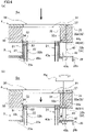
- FIG. 6(a) and FIG. 6(b) show a process of adjusting the height of the block member 30.
- FIG. 7(a) and FIG. 7(b) show a process of detaching the filter member 22.
- FIG. 8 is an enlarged view of the slow cooling unit 4 and its surrounding members after the height adjustment of the block member 30. As described below, the operator is able to perform an adjustment operation of the slow cooling unit 4 and an attachment/detachment operation of the filter member 22.
- the operator performs an operation to activate the air cylinder 28, in a state in which no yarn Y (yarn material) is spun out from the spinning apparatus 2.
- the operator activates the air cylinder 28 to move down the cooling apparatus 3 and the slow cooling unit 4 to switch these apparatuses from the first position (see FIG. 1 ) to the second position (see FIG. 2 and FIG. 6(a) ).
- the working space Sw is a space where the operator is allowed to access the spinnerets 13, the cooling cylinders 21, and the adjustment unit 40. In other words, the operator is allowed to perform operations for the spinnerets 13, the cooling cylinders 21, and the adjustment unit 40 in the working space Sw.
- the block member 30 has been mounted on the mounting portions 41 and the packing 35 has been mounted on the block member 30.
- this state will be referred to as a mounted state.
- the surrounding faces 33 are maintained to surround the upper parts of the cooling cylinders 21.
- the operator In the mounted state, the operator is allowed to perform height adjustment (adjustment operation) of the slow cooling unit 4.
- the operator inserts, for example, a hexagonal wrench Hw into the second through hole 37 of the packing 35 and the second through hole 32 of the block member 30 so as to insert the leading end portion of the hexagonal wrench Hw into a screw hole 42a of the bolt 42.
- the operator rotates the hexagonal wrench Hw about a rotational axis that extends the up-down direction, so as to move the bolt 42 in the up-down direction (i.e., moves the mounting portion 41 in the up-down direction).
- the block member 30 on the mounting portion 41 moves in the up-down direction and the relative positions of the surrounding face 33 and the cooling cylinder 21 are changed in the up-down direction.
- the block member 30 may be supported only by that one mounting portion 41. In such a case, the block member 30 may become imbalanced and slightly tilt relative to the horizontal direction. As a result of this, the surrounding faces 33 may make contact with the cooling cylinders 21 and become immovable. To avoid the block member 30 from becoming immovable, it is necessary to maintain the block member 30 to be substantially horizontally. In order to maintain the block member 30 to be balanced, preferably, two or more mounting portions 41 are simultaneously moved in the up-down direction.
- two or more hexagonal wrenches Hw are inserted into two or more screw holes 42a, respectively, and are simultaneously rotated.
- one operator may simultaneously rotate two hexagonal wrenches Hw.
- two or more operators may simultaneously rotate two or more hexagonal wrenches Hw.
- the operator is able to perform the attachment/detachment operation of the filter member 22.
- the operator detaches an unillustrated screw fixing the lid member 52 to the outer circumferential member 51, by using an unillustrated screwdriver, for example.
- the state of the lid member 52 is changed from the above-described pressing state to the detached state.
- the operator lifts up the lid member 52 and takes it away from the first through hole 31 of the block member 30. In this way, the lid member 52 pressing the filter member 22 from above is detached (see FIG. 7(a) ).
- the operator is allowed to lift up the filter member 22 (the punching filter 22a and the cooling filter 22b connected by the packing 53) and detach the same from the cooling apparatus 3 (see FIG. 7(b) ).
- the filter member 22 may be attached to the cooling apparatus 3 again after, for example, being cleaned.
- a new filter member 22 may be attached to the cooling apparatus 3. In this way, the attachment/detachment operation of the filter member 22 is performed.
- the operator is able to perform, for example, cleaning of the spinneret 13 along with the adjustment operation of the slow cooling unit 4 and/or the attachment/detachment operation of the filter member 22.
- the operator activates the air cylinder 28 to return the cooling apparatus 3 and the slow cooling unit 4 from the second position to the first position.
- the length L in the up-down direction of the slow cooling space Ss is, for example, changed from the length L1 (see FIG. 5 ) before the adjustment to the length L2 (see FIG. 8 ) after the adjustment.
- the block member 30 and the packing 35 receive upward force from the air cylinder 28.
- the gap between the block member 30 and the bottom surface of the spinning apparatus 2 is therefore effectively sealed by the packing 35.
- the top surface of the packing 35 is substantially entirely in contact with the bottom surface of the frame 10 of the spinning apparatus 2. It is unnecessary to precisely position the packing 35 when the cooling apparatus 3 and the slow cooling unit 4 are returned from the second position to the first position.
- the distance in the up-down direction between the spinneret 13 and the cooling apparatus 3 i.e., the length in the up-down direction of the slow cooling space Ss
- the distance in the up-down direction between the spinneret 13 and the cooling apparatus 3 can be changed by adjusting the relative positions in the up-down direction of the block member 30 and the cooling cylinders 21 by the adjustment unit 40. It is therefore possible to change the length L of the slow cooling space Ss in the up-down direction when the number of yarns Y that the yarn spinning system 1 is able to spin out is large, with a small number of members.
- the packing 35 is a heat insulation member. On this account, movement of heat between the spinning apparatus 2 and the block member 30 can be suppressed. It is therefore possible to further suppress variations in temperature of the spinneret 13.
- the block member 30 is arranged to move relative to the cooling apparatus 3 when the cooling apparatus 3 moves to the second position, the block member 30 and the cooling cylinders 21 would be temporarily separated. On this account, when the cooling apparatus 3 is moved from the second position to the first position, it may be necessary to align the surrounding faces 33 with the cooling cylinders 21. This may be time consuming. In this regard, in the present embodiment, the block member 30 move together with the cooling apparatus 3. On this account, when the cooling apparatus 3 is moved, the state in which the surrounding faces 33 surround the respective cooling cylinders 21 is maintained. It is therefore unnecessary to perform the above-described alignment.
- the block member 30 can be easily removed from the mounting portions 41 according to need.
- the position in the up-down direction of the mounting portion 41 can be finely adjusted by a simple structure using the bolt 42.
- the relative positions of the block member 30 and the cooling cylinders 21 can be finely adjusted by a simple structure.
- the adjustment unit 40 includes the base portion (cover member 20b) with which the bolts 42 are screwed.
- Each of the mounting portions 41 is movable in the up-down direction relative to the cover member 20b, together with the corresponding bolt 42. It is therefore possible to move the mounting portions 41 in the up-down direction with a simple structure.
- the mounting portion 41 can be formed by the nut 44 that is typically inexpensive. It is therefore possible to decrease the cost of the members.
- the block member 30 is mounted on the plural mounting portions 41. This makes it possible to maintain the balance of the block member 30 in a suitable manner.
- the filter member 22 can be lifted up and detached from the cooling apparatus 3 without moving the block member 30 relative to the cooling apparatus 3.
- the filter member 22 can be pressed from above by the lid member 52 that is structurally simple, and the filter member 22 can be detached from the cooling apparatus 3.
Landscapes
- Engineering & Computer Science (AREA)
- Mechanical Engineering (AREA)
- Textile Engineering (AREA)
- Spinning Methods And Devices For Manufacturing Artificial Fibers (AREA)
Abstract
Description
- The present invention relates to a yarn spinning system.
- Patent Literature 1 (
Japanese Laid-Open Patent Publication No. 2016-108698 Patent Literature 1, the spinning apparatus has plural spinnerets. The yarn material discharged from each of the spinnerets is cooled by the cooling apparatus and solidified, and becomes a yarn formed of one or more filament. In other words, yarns that are identical in number with the spinnerets are generated. In addition to the above, in the up-down direction, a space (slow cooling space) in which the yarn material discharged from the spinnerets and descend are slowly cooled is formed between the spinning apparatus and the cooling apparatus. An appropriate length in the up-down direction of the slow cooling space (i.e., an appropriate distance between the spinnerets and the cooling apparatus in the up-down direction) varies depending on the type of the yarn material (hereinafter, yarn type), the thickness of each filament, the number of filaments, and so forth. On this account, when the yarn type, etc. is changed, the length (spinneret surface depth in Patent Literature 1) in the up-down direction of the slow cooling space may need to be changed. - In this connection,
Patent Literature 1 recites a spinneret surface depth variable device capable of changing the spinneret surface depth. To be more specific, the spinneret surface depth variable device includes a cylindrical upper hood fixed to the bottom surface of the spinning apparatus and a cylindrical lower hood fixed to the top surface of the cooling apparatus. The upper hood is arranged to surround at least an upper part of the lower hood. The cooling apparatus is arranged to be movable in the up-down direction. As the cooling apparatus and the lower hood move in the up-down direction, the spinneret surface depth is changed while preventing outside air from flowing into the slow cooling space. - The number of yarns spun out from a spinning apparatus at once is recently on the rise. In such a circumstance, the above-described arrangement of providing the upper hood and the lower hood for each yarn requires an increased number of components and results in cost increase of the yarn spinning system.
- An object of the present invention is to allow a slow cooling space to be changed in length in the up-down direction when the number of yarns spun out is large, with a small number of members.
- According to a first aspect of the invention, a yarn spinning system includes: a spinning apparatus which includes spinnerets from which yarns are spun out, respectively; a cooling apparatus which is provided below the spinning apparatus and is configured to cool the yarns spun out from the respective spinnerets; and a slow cooling unit which is provided between the spinning apparatus and the cooling apparatus in an up-down direction, the cooling apparatus including cooling cylinders which extend in the up-down direction, surround the respective yarns, and are arranged to guide cooling wind to the yarns, and the slow cooling unit including: a block member which includes surrounding faces arranged to surround at least parts in the up-down direction of the respective cooling cylinders, the surrounding faces having parts above the cooling cylinders and the parts forming slow cooling spaces in which slow cooling of the yarns is performed; and an adjustment unit which is capable of adjusting relative positions of the block member and the cooling cylinders in the up-down direction.
- According to this aspect of the invention, it is possible to surround the plural cooling cylinders by one block member. Furthermore, the distance in the up-down direction between the spinneret and the cooling apparatus (i.e., the length in the up-down direction of the slow cooling space) can be changed by adjusting the relative positions in the up-down direction of the block member and the cooling cylinders by the adjustment unit. It is therefore possible to change the length of the slow cooling space in the up-down direction when the number of yarns that the yarn spinning system is able to spin out is large, with a small number of members.
- According to a second aspect of the invention, the yarn spinning system of the first aspect further includes a sealing member which is sandwiched between the spinning apparatus and the block member in the up-down direction.
- When the temperature of the spinneret varies, the yarn quality may be deteriorated. According to the aspect of the invention, intrusion of outside air into the slow cooling space through a gap between the spinning apparatus and the block member can be reliably suppressed by the sealing member. It is therefore possible to suppress variations in temperature of the spinneret due to the outside air.
- According to a third aspect of the invention, the yarn spinning system of the second aspect is arranged so that the sealing member is a heat insulation member.
- According to this aspect of the invention, movement of heat between the spinning apparatus and the block member can be suppressed. It is therefore possible to further suppress variations in temperature of the spinneret.
- According to a fourth aspect of the invention, the yarn spinning system of any one of the first to third aspects further includes a movement mechanism which is configured to move the cooling apparatus between a first position where the yarns are spun out from the spinning apparatus and a second position which is below the first position, when the cooling apparatus is at the second position, a working space being formed between the spinning apparatus and the cooling apparatus in the up-down direction to allow operations to be performed for the spinnerets, the cooling cylinders, and the adjustment unit.
- According to the aspect of the invention, by moving the cooling apparatus to the second position, it is possible to perform operations for the spinnerets, the cooling cylinders, and the adjustment unit in the working space. Good workability is achieved for this reason.
- According to a fifth aspect of the invention, the yarn spinning system of the fourth aspect is arranged so that the block member is arranged to move together with the cooling apparatus when the movement mechanism is driven.
- If the block member is arranged to move relative to the cooling apparatus when the cooling apparatus moves to the second position, the block member and the cooling cylinders would be temporarily separated. On this account, when the cooling apparatus is moved from the second position to the first position, it may be necessary to align the surrounding faces with the cooling cylinders. This may be time consuming. According to the aspect of the invention, when the cooling apparatus is moved, the state in which the surrounding faces surround the respective cooling cylinders is maintained. It is therefore unnecessary to perform the above-described alignment.
- According to a sixth aspect of the invention, the yarn spinning system of the fifth aspect is arranged so that the adjustment unit includes at least one mounting portion which allows the block member to be mounted and is movable in the up-down direction relative to the cooling apparatus.
- According to this aspect of the invention, the block member can be easily removed from the at least one mounting portion according to need.
- According to a seventh aspect of the invention, the yarn spinning system of the sixth aspect is arranged so that the adjustment unit includes at least one bolt which extends in the up-down direction and supports the at least one mounting portion, respectively, and the at least one mounting portion is moved in the up-down direction as the at least one bolt is rotated.
- According to this aspect of the invention, the position in the up-down direction of the mounting portion can be finely adjusted by a simple structure using the bolt. To put it differently, the relative positions of the block member and the cooling cylinders can be finely adjusted by a simple structure.
- According to an eighth aspect of the invention, the yarn spinning system of the seventh aspect further includes a base portion with which the at least one bolt is screwed, when the at least one bolt is rotated, the at least one bolt being moved in the up-down direction relative to the base portion, and the at least one mounting portion being movable together with the respective at least one bolt in the up-down direction.
- This aspect of the invention makes it possible to move the at least one mounting portion in the up-down direction with a simple structure.
- According to a ninth aspect of the invention, the yarn spinning system of the eighth aspect is arranged so that the at least one mounting portion includes at least one nut on each of which a mounting surface making contact with the block member is formed, and the at least one nut is fixed to the at least one bolt, respectively.
- According to this aspect of the invention, the at least one mounting portion can be formed by the at least one nut that is typically inexpensive. It is therefore possible to decrease the cost of the members.
- According to a tenth aspect of the invention, the yarn spinning system of any one of the seventh to ninth aspect is arranged so that the block member has at least one working hole which allows an operation for the at least one bolt to be performed while the block member is kept mounted on the at least one mounting portion.
- According to this aspect of the invention, in a state in which the block member is mounted on the at least one mounting portion, a tool for rotating the at least one bolt is inserted into the at least one working hole. In this way, the tool is able to access the at least one bolt. On this account, it is possible to rotate the at least one bolt while the block member is kept mounted on the at least one mounting portion. In other words, it is unnecessary to remove the block member from the at least one mounting portion when the at least one bolt is rotated. It is therefore possible to reduce the labor required for manually adjusting the relative positions of the block member and the cooling cylinders.
- According to an eleventh aspect of the invention, the yarn spinning system of any one of the sixth to tenth aspects is arranged so that the adjustment unit includes plural mounting portions as the at least one mounting portion.
- When only one mounting portion is provided, the block member may become imbalanced and slightly tilt relative to the horizontal direction, depending on the relationship in size between the mounting portion and the block member. In such a case, for example, the block member may make contact with the cooling cylinders, and an operation to adjust the relative positions of the block member and the cooling cylinders may be obstructed. In this connection, according to the aspect of the invention, the block member is mounted on the plural mounting portions. This makes it possible to maintain the balance of the block member in a suitable manner.
- According to a twelfth aspect of the invention, the yarn spinning system of any one of the fifth to eleventh aspects is arranged so that each of the cooling cylinders includes: a filter member which is attachable to and detachable from the cooling apparatus; and a pressing member which is arranged to press the filter member from above, and when the cooling apparatus is at the second position, the pressing member is switchable between a pressing state in which the pressing member presses the filter member from above and a detached state in which the pressing state is canceled and the filter member is allowed to be lifted up.
- When the block member and the cooling apparatus are movable together, it may be necessary to move the block member relative to the cooling apparatus when the filter member is detached from the cooling apparatus, depending on the positional relationship between the pressing member and the block member. According to the aspect of the invention, as the state of the pressing member is switched from the pressing state to the detached state, the filter member can be lifted up and detached from the cooling apparatus without moving the block member relative to the cooling apparatus.
- According to a thirteenth aspect of the invention, the yarn spinning system of the twelfth aspect is arranged so that the pressing member is a ring member which is attachable to and detachable from a top surface of each of the cooling cylinders.
- According to the aspect of the invention, the filter member can be pressed from above by the pressing member that is structurally simple, and the filter member can be detached from the cooling apparatus.
- According to a fourteenth aspect of the invention, the yarn spinning system of any one of the first to thirteenth aspects is arranged so that the cooling cylinders include extension portions extending downward as compared to a bottom surface of the block member, respectively, and at least one covering member is provided to be movable at least in the up-down direction relative to the extension portions and to cover gaps between the cooling cylinders and the surrounding faces.
- When the gap between the surrounding face of the block member and the outer circumferential surface of the cooling cylinder is wide, outside air tends to enter the slow cooling space, and the yarn quality may be deteriorated. On this account, the gap is preferably as narrow as possible. However, when the gap is too narrow, the surrounding face of the block member tends to make contact with the outer circumferential surface of the cooling cylinder when the relative positions of the block member and the cooling cylinders is adjusted in the up-down direction. This may prevent the relative movement of the block member and the cooling cylinders, and the adjustment may become difficult. According to the present invention, when the yarns are produced, the gap between the surrounding face of the block member and the outer circumferential surface of the cooling cylinder is covered with the covering member. On this account, even when the gap is wide, intrusion of the outside air into the slow cooling space is prevented. Easiness of the positional adjustment of the block member and good yarn quality are both achieved with this arrangement.
- According to a fifteenth aspect of the invention, the yarn spinning system of the fourteenth aspect is arranged so that the at least one covering member is attachable to and detachable from the extension portions.
- According to this aspect of the invention, the covering member does not obstruct the adjustment of the relative positions of the surrounding face of the block member and the cooling cylinder.
-
-
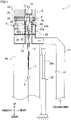
FIG. 1 is a schematic representation of a yarn spinning system of an embodiment. -
FIG. 2 illustrates a state in which a cooling apparatus and a slow cooling unit are at a second position. -
FIG. 3 is a perspective view of the slow cooling unit and its surroundings. -
FIG. 4 is a perspective view showing a state in which a block member is lifted up from an adjustment unit. -
FIG. 5 is an enlarged view of the slow cooling unit and its surrounding members. -
FIG. 6(a) and FIG. 6(b) show a process of adjusting the height of the block member. -
FIG. 7(a) and FIG. 7(b) show a process of detaching a filter member. -
FIG. 8 is an enlarged view of the slow cooling unit and its surrounding members after adjustment. -
FIG. 9 shows a slow cooling unit of a modification and its surrounding members. - The following will describe an embodiment of the present invention. Hereinafter, directions shown in
FIG. 1 will be consistently used as an up-down direction and a front-rear direction, for convenience of explanation. The up-down direction (the up-down direction in the plane ofFIG. 1 ) is a vertical direction in which the gravity acts. The front-rear direction (the left-right direction in the plane ofFIG. 1 ) is a direction orthogonal to the up-down direction. A direction orthogonal to both the up-down direction and the front-rear direction (i.e., a direction perpendicular to the plane ofFIG. 1 ) is set as a left-right direction. - The following will outline a
yarn spinning system 1 of the present embodiment, with reference to the schematic representation ofFIG. 1 . Theyarn spinning system 1 is a system configured to generate yarns Y formed of synthetic fibers. Theyarn spinning system 1 includes aspinning apparatus 2, acooling apparatus 3, aslow cooling unit 4, and anoil applicator 5. - The
spinning apparatus 2 is a melt spinning device configured to spin out yarns Y made of molten polymer. Thespinning apparatus 2 includes aframe 10 that is substantially rectangular parallelepiped in shape,pack housings 11 formed in theframe 10, and spinning packs 12 attached to the respective pack housings 11. The spinning packs 12 are, for example, staggered to form two lines along the left-right direction. (The packs are not illustrated. As to the arrangement in the horizontal direction, see, e.g., coolingcylinders 21 and first throughholes 31 described below and shown inFIG. 4 .) To each spinningpack 12, hot liquid molten polymer (yarn material) is supplied from an unillustrated pipe. At a lower end portion of each spinningpack 12, aspinneret 13 is provided. Thespinneret 13 has, for example, plural nozzles (not illustrated). The spinningpack 12 spins the yarn material out from the nozzles of the spinneret 13 (i.e., spins out a yarn Y). The yarn material spun out through the nozzles is cooled at thecooling apparatus 3 so that the yarn Y constituted by filaments f is formed. As such, one yarn Y is spun out from onespinneret 13. Alternatively, eachspinneret 13 has only one nozzle. In such a case, the yarn Y is a mono-filament yarn. It is noted that the yarn material immediately after being discharged from the spinneret 13 (i.e., before cooled and solidified) is also equivalent to the yarn of the present invention. - The
cooling apparatus 3 is configured to cool and solidify the yarn material discharged from thespinnerets 13, by means of cooling wind. Thecooling apparatus 3 is provided below thespinning apparatus 2. As shown inFIG. 1 , thecooling apparatus 3 includes ahollow box 20 andcooling cylinders 21.FIG. 1 shows only onecooling cylinder 21. - The
box 20 includes amain body 20a and acover member 20b provided above themain body 20a. In the present embodiment, an end portion of thecover member 20b in the horizontal direction is bended downward. The shape of thecover member 20b is not limited to this. Thecover member 20b may be a simple flat plate in shape, for example. The labor for manufacturing thecover member 20b is reduced in this case. Thecover member 20b is screwed with themain body 20a by an unillustrated screw, for example. When unscrewed, thecover member 20b can be detached from themain body 20a. As shown inFIG. 1 , for example, the internal space of thebox 20 is partitioned into an upper space and a lower space by aflow adjustment plate 26 that is substantially horizontally provided. Theflow adjustment plate 26 is made of a material having flow adjustment capability such as punching metal. - The cooling
cylinders 21 are arranged to guide cooling wind to the yarn material. The coolingcylinders 21 are fixed to thebox 20. The coolingcylinders 21 extend in the up-down direction. The coolingcylinders 21 are provided immediately below therespective spinnerets 13. In other words, when viewed in the up-down direction, the coolingcylinder 21 is provided to surround the yarn material spun out from thespinneret 13. Each coolingcylinder 21 includes afilter member 22 and an uppercylindrical member 23. - The
filter member 22 is a member for guiding cooling wind inward in the radial direction of thecorresponding cooling cylinder 21. Thefilter member 22 includes a punchingfilter 22a and acooling filter 22b. The punchingfilter 22a is a substantially cylindrical member. Being similar to theflow adjustment plate 26, the punchingfilter 22a is also formed of a material having flow adjustment capability such as punching metal. The punchingfilter 22a extends upward from the position of the lower end portion of the upper space (that is a space above the flow adjustment plate 26) of thebox 20 and protrudes upward as compared to the upper end of thecover member 20b. An upper end portion of the punchingfilter 22a is provided inside the uppercylindrical member 23 in the radial direction of thecooling cylinder 21. Thecooling filter 22b is substantially cylindrical in shape. A circumferential wall portion of thecooling filter 22b is, for example, made of a mesh material having flow adjustment capability. Thecooling filter 22b is provided inside the punchingfilter 22a in the radial direction. Being similar to the punchingfilter 22a, thecooling filter 22b protrudes upward as compared to the upper end of thecover member 20b. - The upper
cylindrical member 23 is a substantially cylindrical member. The uppercylindrical member 23 is, for example, fixed to an upper plate portion that is at the uppermost part of thecover member 20b. For example, a flange is formed at a lower end portion of the uppercylindrical member 23 and the flange is fixed to the bottom surface of the upper plate portion of thecover member 20b. The uppercylindrical member 23 is provided to surround thefilter member 22 and press thefilter member 22 from above. The uppercylindrical member 23 is arranged not to allow air to pass through in the radial direction of thecooling cylinder 21. This suppresses the outside air to flow into the inside of thecooling cylinder 21 in the radial direction of thecooling cylinder 21. The coolingcylinder 21 is arranged to guide cooling wind upward (to the vicinity of the upper end portion of the cooling cylinder 21). - In the lower space of the box 20 (i.e., the space lower than the flow adjustment plate 26) and directly below the
filter members 22,partitioning cylinders 24 are provided. Eachpartitioning cylinder 24 is arranged not to allow air to pass through in the radial direction of thepartitioning cylinder 24. The yarn material which is discharged from aspinneret 13 and descends passes through the internal space of thefilter member 22 directly below thespinneret 13 and the internal space of thepartitioning cylinder 24 in this order. - To a rear part of a lower portion of the
box 20, aduct 27 is connected. Theduct 27 is connected to a compressed air source (not illustrated). The compressed air source supplies air for cooling the yarn material to the inside of theduct 27. The cooling air is supplied into the lower space of thebox 20 through theduct 27. The flow of the air in thebox 20 will be described below. (See the arrows inFIG. 1 .) The air which flows into the lower space of thebox 20 passes through theflow adjustment plate 26 to be adjusted to flow upward, and flows into the upper space of thebox 20. In this regard, because the wall of thepartitioning cylinder 24 does not allow air to pass through, air does not directly flow from the lower space of thebox 20 into thepartitioning cylinder 24. The air flowing into the upper space of thebox 20 is adjusted when passing through the filter member 22 (the punchingfilter 22a and thecooling filter 22b), and flows into the inside of thefilter member 22 in the radial direction. As a result, the air is blown onto the yarn material from the entire outer circumference of thefilter member 22, and the yarn material is cooled and made into the yarn Y. - The
cooling apparatus 3 is arranged to be able to move up and down by an air cylinder 28 (movement mechanism of the present invention). To be more specific, theair cylinder 28 stands on the floor surface of a factory, for example. Apiston rod 28a extends in the up-down direction. To the lower end of thebox 20, acover member 29 extending downward is fixed. To a side face of thecover member 29, a leading end portion of thepiston rod 28a is fixed. With this arrangement, as theair cylinder 28 is driven, the entirety of thecooling apparatus 3 is movable between a first position (seeFIG. 1 ) where theyarn spinning system 1 operates and a second position (seeFIG. 2 ) below the first position. When thecooling apparatus 3 is at the first position, the yarns Y can be generated. When thecooling apparatus 3 is at the first position, upward force (toward the spinning apparatus 2) is applied to thecooling apparatus 3 and theslow cooling unit 4 by theair cylinder 28. When thecooling apparatus 3 is at the second position, a working space Sw (detailed later) is formed between the spinningapparatus 2 and thecooling apparatus 3 in the up-down direction. - The
slow cooling unit 4 is provided between the spinningapparatus 2 and thecooling apparatus 3 in the up-down direction. Theslow cooling unit 4 is arranged to gradually cool the yarn material (i.e., perform slow cooling) until the yarn material discharged from thespinning apparatus 2 is cooled by thecooling apparatus 3. Theslow cooling unit 4 has a slow cooling space Ss for slow cooling of the yarn material. Theslow cooling unit 4 will be detailed later. - The
oil applicator 5 is configured to apply oil to the yarns Y. Theoil applicator 5 is provided below thecooling apparatus 3. Theoil applicator 5 includes oil guides (not illustrated) with which the yarns Y cooled by thecooling apparatus 3 make contact, respectively. At this stage, the oil guides discharge and apply oil to the respective yarns Y. The yarns Y to which the oil has been applied by theoil applicator 5 are taken up by a take-up roller (not illustrated). The yarns Y are then fed to a winding device (not illustrated). The yarns Y are wound onto bobbins (not illustrated) at the winding device. - The arrangement of the
slow cooling unit 4 will be detailed with reference toFIG. 3 to FIG. 5 .FIG. 3 is a perspective view of theslow cooling unit 4 and its surroundings.FIG. 4 is a perspective view showing a state in which a block member 30 (described later) is lifted up from an adjustment unit 40 (described later).FIG. 5 is an enlarged view of theslow cooling unit 4 and its surrounding members. An appropriate length in the up-down direction of the above-described slow cooling space Ss (to be more specific, an appropriate distance between the bottom surface of thespinneret 13 and upper end of thecooling cylinder 21 in the up-down direction) varies depending on the type of the yarns Y to be produced, the thickness of each filament f, the number of filaments f, and so forth. Members such as theslow cooling unit 4 are arranged as described below in order to allow the slow cooling space Ss to be changed in length in the up-down direction when the number of yarns Y that theyarn spinning system 1 is able to spin out is large, with a small number of members. - The
slow cooling unit 4 includes theblock member 30 and theadjustment unit 40. Theblock member 30 is a member for forming the slow cooling space Ss. Theadjustment unit 40 is arranged to be able to adjust the positional relationship between theblock member 30 and thecooling cylinder 21 in the up-down direction. As described below, theadjustment unit 40 is therefore able to adjust the distance between thebottom surface 13a (seeFIG. 5 ) of thespinneret 13 and the upper end of thecooling cylinder 21 in the up-down direction (i.e., the length L of the slow cooling space Ss in the up-down direction shown inFIG. 5 ). - As shown in
FIG. 3 andFIG. 4 , theblock member 30 is substantially rectangular parallelepiped in shape. Theblock member 30 is a metal member made of, for example, aluminum alloy. Theblock member 30 is mounted on mounting portions 41 (described below) of theadjustment unit 40. Theblock member 30 is provided above thebox 20. Theblock member 30 has first throughholes 31 penetrating the member in the up-down direction and second through holes 32 (working holes of the present invention) also penetrating the member in the up-down direction. Theblock member 30 is, for example, solid except at the parts where the first throughholes 31 and the second throughholes 32 are formed. The first throughholes 31 are formed at positions corresponding to therespective cooling cylinders 21 in the horizontal direction. In the present embodiment, the first throughholes 31 are staggered to form two lines along the left-right direction (seeFIG. 3 andFIG. 4 ). The first throughholes 31 allow the cooling cylinders 21 (to be more specific, the uppercylindrical members 23 except the flanges at the lower end portions and their surroundings) to be inserted into the holes in the up-down direction. To put it differently, theblock member 30 has surroundingfaces 33 forming the first through holes 31. Each of the surrounding faces 33 is substantially circular when viewed in the up-down direction. The surrounding faces 33 are arranged to surround at least upper parts (at least parts in the up-down direction) of the cooling cylinders 21 (seeFIG. 5 ). In the surrounding faces 33, parts above the coolingcylinders 21 form the slow cooling space Ss. The second throughholes 32 are formed at positions corresponding to the below-described respective mountingportions 41 in the horizontal direction. Each second throughhole 32 has, for example, asmall diameter portion 32a and alarge diameter portion 32b. Thesmall diameter portion 32a extends from the upper end of theblock member 30 to an intermediate part of the second throughhole 32 in the up-down direction. Thelarge diameter portion 32b is provided below thesmall diameter portion 32a and extends to reach the lower end of theblock member 30. Thelarge diameter portion 32b is larger in diameter than thesmall diameter portion 32a. Therefore acontact surface 32c facing downward is formed at the border between thesmall diameter portion 32a and thelarge diameter portion 32b. Thecontact surface 32c is able to make contact with the later-described mountingportion 41. Theblock member 30 can be mounted on the plural mountingportions 41. Furthermore, theblock member 30 can be moved relative to the plural mountingportions 41 by an operator. - Between each of the surrounding faces 33 and the outer circumferential surface of each of the cooling cylinders 21 (i.e., the outer
circumferential surface 23a of the upper cylindrical member 23), agap 34 is formed. Thegap 34 is formed to minimize a possibility that the surroundingface 33 and the cooling cylinder 21 (upper cylindrical member 23) make contact with each other and become immovable in a later-described adjustment operation. Meanwhile, thegap 34 is preferably as narrow as possible in order to suppress the intrusion of the outside air into the slow cooling space Ss. - As shown in
FIG. 3 to FIG. 5 , a plate-shapedpacking 35 is mounted on the top surface of theblock member 30 to extend substantially horizontally. The packing 35 is a sealing member for sealing a gap between the bottom surface of thespinning apparatus 2 and the top surface of theblock member 30. The packing 35 is preferably a rubber member having elasticity and heat resistance, for example. The packing 35 is preferably a heat insulation member having heat insulating properties. The packing 35 is provided to be sandwiched between the spinningapparatus 2 and theblock member 30 in the up-down direction when thecooling apparatus 3 and theslow cooling unit 4 are at the first position. The packing 35 is arranged to be separatable from theblock member 30, for example. When viewed in the up-down direction, the packing 35 is substantially identical in size with theblock member 30. The top surface of the packing 35 is substantially entirely in contact with the bottom surface of theframe 10 of thespinning apparatus 2. The packing 35 has first throughholes 36 and second throughholes 37 penetrating therethrough in the up-down direction. The first throughholes 36 are provided at substantially same positions as the first throughholes 31 in the horizontal direction. When viewed in the up-down direction, each of the first throughholes 36 is identical with or slightly smaller than each of the first throughholes 31 in size. The second throughholes 37 are provided at substantially same positions as the second throughholes 32 in the horizontal direction. - The
adjustment unit 40 includes, for example, the mountingportions 41 allowing theblock member 30 to be mounted thereon,bolts 42 for moving the mountingportions 41 in the up-down direction, and the above-describedcover member 20b. Thecover member 20b supports thebolts 42. Thecover member 20b is equivalent to a base portion of the present invention. As described below, the mountingportions 41 are supported by thebox 20 to be movable in the up-down direction. It is therefore possible to change the relative positions of theblock member 30 and the coolingcylinders 21 in the up-down direction. Some mountingportions 41 among the mountingportions 41 are, for example, provided to support the four corners of theblock member 30 in the horizontal direction. Another mountingportion 41 among the mountingportions 41 may be, for example, provided to be sandwiched between two first throughholes 31 in the left-right direction (seeFIG. 3 andFIG. 4 ). - Each mounting
portion 41 has anut 44. Thenut 44 has an unillustrated female screw and is screwed with thebolt 42. Thenut 44 screwed with thebolt 42 is fixed to thebolt 42 by, for example, welding. Thenut 44 is therefore rotatable together with thebolt 42. Thetop surface 44a (mounting surface of the present invention) of thenut 44 is capable of making contact with the above-describedcontact surface 32c of theblock member 30. - The
bolt 42 of the present embodiment is, for example, a known fully-threaded screw without a head or a known stud bolt. Thebolt 42 extends in the up-down direction. A lower part of thebolt 42 is supported by thecover member 20b. Thenut 44 is fixed to an upper part of thebolt 42. Thebolt 42 is rotatable together with thenut 44. At an upper end portion of thebolt 42, ascrew hole 42a (seeFIG. 4 ) is formed. Thescrew hole 42a is, for example, a hexagonal hole. - The
cover member 20b is arranged so that thebolts 42 are screwed therewith. To be more specific, for example,insertion holes 43a are formed in a top surface portion of thecover member 20b to allow thebolts 42 to be inserted thereto. Immediately below eachinsertion hole 43a, for example, anut 43b is provided. Thenut 43b is fixed to thecover member 20b by, for example, welding. In the present embodiment, thenut 43b is included in thecover member 20b. A lower part of thebolt 42 is screwed with thenut 43b. As the bolts 42 (and the mounting portions 41) are rotated, thebolts 42 and the mountingportions 41 are movable in the up-down direction relative to thecover member 20b (i.e., relative to the cooling apparatus 3). - The mounting
portions 41 and thebolts 42 move in the up-down direction together with thecover member 20b (box 20) when thecooling apparatus 3 is moved in the up-down direction by the air cylinder 28 (seeFIG. 1 andFIG. 2 ) . On this account, theblock member 30 mounted on the mountingportions 41 move in the up-down direction together with thecooling apparatus 3 when theair cylinder 28 is driven. - The structure of the cooling
cylinders 21 will be further detailed with reference toFIG. 5 . As described above, each of the coolingcylinders 21 includes the filter member 22 (the punchingfilter 22a and thecooling filter 22b) and the uppercylindrical member 23. An upper end portion of the punchingfilter 22a is connected to an upper end portion of thecooling filter 22b by a packing 53. Although not illustrated, a lower end portion of the punchingfilter 22a is also connected to a lower end portion of thecooling filter 22b by a packing (not illustrated). The uppercylindrical member 23 includes an outercircumferential member 51 and a lid member 52 (pressing member of the present invention). The outercircumferential member 51 is a substantially cylindrical portion fixed to thebox 20 by, for example, an unillustrated screw. In the radial direction of thefilter member 22, the outercircumferential member 51 is provided outside thefilter member 22. In other words, thefilter member 22 is provided inside the outercircumferential member 51 in the radial direction. In other words, when viewed in the up-down direction, thefilter member 22 is provided to be surrounded by the outercircumferential member 51. Thelid member 52 is ring-shaped. Thelid member 52 is arranged to be able to press thefilter member 22 from above through, for example, the packing 53. Thelid member 52 therefore prevents thefilter member 22 from unintentionally moving in the up-down direction. Thelid member 52 is fixed to the top surface of the outercircumferential member 51 by, for example, an unillustrated screw. Thelid member 52 is arranged to be detachable from and attachable to the outercircumferential member 51. That is to say, thelid member 52 is arranged to be switchable between a pressing state of being screwed onto the top surface of the outercircumferential member 51 and a detached state of being detached from the outercircumferential member 51. When thelid member 52 is in the pressing state, thelid member 52 presses thefilter member 22 from above. When thelid member 52 is in the detached state, the state in which thelid member 52 presses thefilter member 22 from above has been canceled and thefilter member 22 can be lifted up from thebox 20. The packing 53 is a sealing member in contact with the bottom surface of thelid member 52. As described above, the packing 53 connects the punchingfilter 22a with thecooling filter 22b. - The following will describe an operation method performed by an operator in the
yarn spinning system 1 structured as described above, with reference toFIG. 6(a) to FIG. 8 .FIG. 6(a) and FIG. 6(b) show a process of adjusting the height of theblock member 30.FIG. 7(a) and FIG. 7(b) show a process of detaching thefilter member 22.FIG. 8 is an enlarged view of theslow cooling unit 4 and its surrounding members after the height adjustment of theblock member 30. As described below, the operator is able to perform an adjustment operation of theslow cooling unit 4 and an attachment/detachment operation of thefilter member 22. - To begin with, the operator performs an operation to activate the
air cylinder 28, in a state in which no yarn Y (yarn material) is spun out from thespinning apparatus 2. To be more specific, the operator activates theair cylinder 28 to move down thecooling apparatus 3 and theslow cooling unit 4 to switch these apparatuses from the first position (seeFIG. 1 ) to the second position (seeFIG. 2 andFIG. 6(a) ). As a result, the above-described working space Sw is formed. The working space Sw is a space where the operator is allowed to access thespinnerets 13, the coolingcylinders 21, and theadjustment unit 40. In other words, the operator is allowed to perform operations for thespinnerets 13, the coolingcylinders 21, and theadjustment unit 40 in the working space Sw. - After the
cooling apparatus 3 and theslow cooling unit 4 are moved to the second position, theblock member 30 has been mounted on the mountingportions 41 and the packing 35 has been mounted on theblock member 30. Hereinafter, this state will be referred to as a mounted state. In the mounted state, the surrounding faces 33 are maintained to surround the upper parts of the coolingcylinders 21. - In the mounted state, the operator is allowed to perform height adjustment (adjustment operation) of the
slow cooling unit 4. To be more specific, as shown inFIG. 6(b) , in the working space Sw, the operator inserts, for example, a hexagonal wrench Hw into the second throughhole 37 of the packing 35 and the second throughhole 32 of theblock member 30 so as to insert the leading end portion of the hexagonal wrench Hw into ascrew hole 42a of thebolt 42. The operator rotates the hexagonal wrench Hw about a rotational axis that extends the up-down direction, so as to move thebolt 42 in the up-down direction (i.e., moves the mountingportion 41 in the up-down direction). As a result, theblock member 30 on the mountingportion 41 moves in the up-down direction and the relative positions of the surroundingface 33 and thecooling cylinder 21 are changed in the up-down direction. - It is noted that, if only one mounting
portion 41 is moved in the up-down direction when theblock member 30 is moved in the up-down direction, theblock member 30 may be supported only by thatone mounting portion 41. In such a case, theblock member 30 may become imbalanced and slightly tilt relative to the horizontal direction. As a result of this, the surrounding faces 33 may make contact with the coolingcylinders 21 and become immovable. To avoid theblock member 30 from becoming immovable, it is necessary to maintain theblock member 30 to be substantially horizontally. In order to maintain theblock member 30 to be balanced, preferably, two or more mountingportions 41 are simultaneously moved in the up-down direction. In other words, preferably, two or more hexagonal wrenches Hw are inserted into two ormore screw holes 42a, respectively, and are simultaneously rotated. For example, one operator may simultaneously rotate two hexagonal wrenches Hw. Alternatively, two or more operators may simultaneously rotate two or more hexagonal wrenches Hw. - In the above-described mounted state, the operator is able to perform the attachment/detachment operation of the
filter member 22. The operator detaches an unillustrated screw fixing thelid member 52 to the outercircumferential member 51, by using an unillustrated screwdriver, for example. As a result of this, the state of thelid member 52 is changed from the above-described pressing state to the detached state. Thereafter, the operator lifts up thelid member 52 and takes it away from the first throughhole 31 of theblock member 30. In this way, thelid member 52 pressing thefilter member 22 from above is detached (seeFIG. 7(a) ). Thereafter, the operator is allowed to lift up the filter member 22 (the punchingfilter 22a and thecooling filter 22b connected by the packing 53) and detach the same from the cooling apparatus 3 (seeFIG. 7(b) ). Thefilter member 22 may be attached to thecooling apparatus 3 again after, for example, being cleaned. Alternatively, anew filter member 22 may be attached to thecooling apparatus 3. In this way, the attachment/detachment operation of thefilter member 22 is performed. - In addition to the above, in the working space Sw, the operator is able to perform, for example, cleaning of the
spinneret 13 along with the adjustment operation of theslow cooling unit 4 and/or the attachment/detachment operation of thefilter member 22. - Thereafter, the operator activates the
air cylinder 28 to return thecooling apparatus 3 and theslow cooling unit 4 from the second position to the first position. As a result of this, the length L in the up-down direction of the slow cooling space Ss is, for example, changed from the length L1 (seeFIG. 5 ) before the adjustment to the length L2 (seeFIG. 8 ) after the adjustment. Theblock member 30 and the packing 35 receive upward force from theair cylinder 28. The gap between theblock member 30 and the bottom surface of thespinning apparatus 2 is therefore effectively sealed by the packing 35. Furthermore, the top surface of the packing 35 is substantially entirely in contact with the bottom surface of theframe 10 of thespinning apparatus 2. It is unnecessary to precisely position the packing 35 when thecooling apparatus 3 and theslow cooling unit 4 are returned from the second position to the first position. - As described above, it is possible to surround the
plural cooling cylinders 21 by oneblock member 30. Furthermore, the distance in the up-down direction between thespinneret 13 and the cooling apparatus 3 (i.e., the length in the up-down direction of the slow cooling space Ss) can be changed by adjusting the relative positions in the up-down direction of theblock member 30 and the coolingcylinders 21 by theadjustment unit 40. It is therefore possible to change the length L of the slow cooling space Ss in the up-down direction when the number of yarns Y that theyarn spinning system 1 is able to spin out is large, with a small number of members. - In addition to the above, intrusion of outside air into the slow cooling space Ss through a gap between the spinning
apparatus 2 and theblock member 30 can be reliably suppressed by the packing 35 that is a sealing member. It is therefore possible to suppress variations in temperature of thespinneret 13 due to the outside air. - In addition to the above, the packing 35 is a heat insulation member. On this account, movement of heat between the spinning
apparatus 2 and theblock member 30 can be suppressed. It is therefore possible to further suppress variations in temperature of thespinneret 13. - In addition to the above, by moving the
cooling apparatus 3 to the second position, it is possible to perform operations for thespinnerets 13, the coolingcylinders 21, and theadjustment unit 40 in the working space Sw. Good workability is achieved for this reason. - If the
block member 30 is arranged to move relative to thecooling apparatus 3 when thecooling apparatus 3 moves to the second position, theblock member 30 and the coolingcylinders 21 would be temporarily separated. On this account, when thecooling apparatus 3 is moved from the second position to the first position, it may be necessary to align the surrounding faces 33 with the coolingcylinders 21. This may be time consuming. In this regard, in the present embodiment, theblock member 30 move together with thecooling apparatus 3. On this account, when thecooling apparatus 3 is moved, the state in which the surrounding faces 33 surround therespective cooling cylinders 21 is maintained. It is therefore unnecessary to perform the above-described alignment. - In the present embodiment, the
block member 30 can be easily removed from the mountingportions 41 according to need. - In addition to the above, the position in the up-down direction of the mounting
portion 41 can be finely adjusted by a simple structure using thebolt 42. To put it differently, the relative positions of theblock member 30 and the coolingcylinders 21 can be finely adjusted by a simple structure. - In addition to the above, the
adjustment unit 40 includes the base portion (covermember 20b) with which thebolts 42 are screwed. Each of the mountingportions 41 is movable in the up-down direction relative to thecover member 20b, together with the correspondingbolt 42. It is therefore possible to move the mountingportions 41 in the up-down direction with a simple structure. - In addition to the above, the mounting
portion 41 can be formed by thenut 44 that is typically inexpensive. It is therefore possible to decrease the cost of the members. - In addition to the above, in a state in which the
block member 30 is mounted on the mountingportion 41, a tool (hexagonal wrench Hw in the present embodiment) for rotating thebolt 42 is inserted into the second throughhole 32. In this way, the tool is able to access thebolt 42. On this account, it is possible to rotate thebolt 42 while theblock member 30 is kept mounted on the mountingportion 41. In other words, it is unnecessary to remove theblock member 30 from the mountingportion 41 when thebolt 42 is rotated. It is therefore possible to reduce the labor required for manually adjusting the relative positions of theblock member 30 and the coolingcylinders 21. - In addition to the above, the
block member 30 is mounted on the plural mountingportions 41. This makes it possible to maintain the balance of theblock member 30 in a suitable manner. - In addition to the above, as the state of the
lid member 52 is switched from the pressing state to the detached state, thefilter member 22 can be lifted up and detached from thecooling apparatus 3 without moving theblock member 30 relative to thecooling apparatus 3. - In addition to the above, the
filter member 22 can be pressed from above by thelid member 52 that is structurally simple, and thefilter member 22 can be detached from thecooling apparatus 3. - The following will describe modifications of the above-described embodiment. The members identical with those in the embodiment above will be denoted by the same reference numerals and the explanations thereof are not repeated.
- (1) The
yarn spinning system 1 may include coveringmembers 60 shown inFIG. 9 . Each coveringmember 60 covers a lower end portion of thegap 34 formed between the surroundingface 33 of theblock member 30 and the cooling cylinder 21 (to be more specific, the outercircumferential surface 23a of the upper cylindrical member 23). The coveringmember 60 is arranged to be movable at least in the up-down direction relative to anextension portion 23E which is a part of the cooling cylinder 21 (upper cylindrical member 23) and extends downward as compared to the bottom surface of theblock member 30. Each of the coveringmembers 60 may be a rubber ring arranged to surround theextension portion 23E, for example. In this way, thegap 34 can be covered with the coveringmember 60 when the yarns Y are produced. On this account, even when thegap 34 is wide, intrusion of the outside air into the slow cooling space Ss is prevented. Easiness of the positional adjustment of theblock member 30 and good yarn quality are both achieved with this arrangement. Alternatively, each coveringmember 60 may be attachable to and detachable from the cooling cylinder 21 (upper cylindrical member 23). In other words, the coveringmember 60 may be a ring member having plural ring pieces (not illustrated) provided along the circumferential direction, for example. With this arrangement, the coveringmember 60 does not obstruct the adjustment operation. In this modification, a single covering member (not illustrated) may be provided to cover all of thegaps 34. Alternatively, plural covering members (not illustrated) each covering some of thegaps 34 may be provided. - (2) While in the embodiment above the
lid member 52 of thecooling cylinder 21 is screwed with the outercircumferential member 51, the disclosure is not limited to this arrangement. Each of thelid member 52 and the outercircumferential member 51 may be provided with an unillustrated magnet, for example. With this arrangement, thelid member 52 may be detachably attached to the outercircumferential member 51 by magnetic force. Furthermore, thelid member 52 may not be ring-shaped. Thelid member 52 may have any shape as long as the state thereof is switchable between the pressing state and the detached state that are described above. - (3) While in the embodiment above the
lid member 52 is attachable to and detachable from the outercircumferential member 51, the disclosure is not limited to this arrangement. Thelid member 52 may be fixed to the outercircumferential member 51 by, for example, welding. Alternatively, the coolingcylinders 21 may be molded by a single member. It is noted that, in these cases, thecover member 20b of thebox 20 needs to be separated from themain body 20a when the attachment/detachment operation of thefilter member 22 is performed. On this account, as a preparation, theblock member 30 must be lifted up and removed from the mountingportions 41. - (4) The positions of the mounting
portions 41 in the horizontal direction are not limited to those described above. The mountingportions 41 are preferably designed to be at optimal positions in consideration of the workability of the adjustment of the height of theblock member 30. - (5) The second through
hole 32 of theblock member 30 may not penetrate theblock member 30 in the up-down direction. The second throughhole 32 may extend in, for example, an oblique direction as long as a tool is able to access thebolt 42. Alternatively, the second throughhole 32 may not be formed. In such a case, however, theblock member 30 needs to be removed from the mountingportions 41 when the adjustment operation is performed. - (6) While in the embodiment above the
adjustment unit 40 includes the mountingportions 41, the disclosure is not limited to this arrangement. Theadjustment unit 40 may have a single large mounting portion (not illustrated). Such a mounting portion may be supported or one orplural bolts 42. - (7) While in the embodiment above the mounting
portion 41 includes thenut 44, the disclosure is not limited to this arrangement. The mountingportion 41 may be composed of a member that is not thenut 44. For example, while in the embodiment above thebolt 42 does not have a head, the disclosure is not limited to this arrangement. Thebolt 42 may have a head with a hexagonal hole, for example. This head may function as the mounting portion of the present invention. Thebolt 42 may be a screw hole (not illustrated) that is not a hexagonal hole. When thebolt 42 has a head, a screw hole may not be formed in the head. In other words, for example, a known hexagonal bolt having a head that is substantially hexagonal cylinder in shape may be equivalent to both the mounting portion and the bolt of the present invention. In such a case, however, theblock member 30 needs to be removed from the mountingportions 41 when the adjustment operation is performed. - (8) The base portion (cover
member 20b) may not be structured as described above. While in the example above thenut 43b is fixed to thecover member 20b, the disclosure is not limited to this arrangement. For example, a female screw may be made in theinsertion hole 43a formed in thecover member 20b. Thebolt 42 may be screwed with theinsertion hole 43a. Alternatively, the base portion may be formed by a member (not illustrated) different from thecover member 20b. - (9) In the embodiment above, the
adjustment unit 40 has thebolt 42 extending in the up-down direction and the mountingportion 41 moves in the up-down direction together with thebolt 42. However, the disclosure is not limited to this. An adjustment unit (not illustrated) may include, for example, a rack-and-pinion mechanism constituted by a rack (not illustrated) and a pinion gear (not illustrated) . To be more specific, a mounting portion (not illustrated) may be provided on a rack extending in the up-down direction. In this case, the pinion gear may be substantially orthogonal to the up-down direction. As the pinion gear is rotated, the rack (mounting portion) may be moved in the up-down direction. Alternatively, the adjustment unit (not illustrated) may include, for example, an unillustrated jack (e.g., a pantograph jack). For example, two pantograph jacks (not illustrated) may be provided between theblock member 30 and the box 20 (covermember 20b) in the up-down direction. The two pantograph jacks may be provided to support end portions in the longitudinal direction (left-right direction) of theblock member 30, respectively. - (10) In the embodiment above, the
adjustment unit 40 includes the mountingportion 41 and theblock member 30 is mounted on the mountingportion 41. In other words, theblock member 30 is arranged to be easily detached from theadjustment unit 40 and thecooling apparatus 3. However, the disclosure is not limited to this. For example, theblock member 30 is not easily detached from or cannot be detached from theadjustment unit 40. - (11) In the embodiment above, when the
air cylinder 28 is activated, theblock member 30 moves together with thecooling apparatus 3. However, the disclosure is not limited to this. Theblock member 30 may be, for example, fixed to thespinning apparatus 2. In other words, theslow cooling unit 4 may be arranged such that theadjustment unit 40 is detached from theblock member 30 when theair cylinder 28 moves thecooling apparatus 3 from the first position to the second position. Furthermore, the packing 35 may not be provided between the spinningapparatus 2 and theblock member 30. - (12) In the embodiment above, the working space Sw is formed when the
air cylinder 28 moves thecooling apparatus 3 from the first position to the second position. In other words, the working space Sw allows operations to be performed for thespinnerets 13, the coolingcylinders 21, and theadjustment unit 40. However, the disclosure is not limited to this. For example, operations can be performed in the working space Sw only for the coolingcylinders 21 and theadjustment unit 40. - (13) In the embodiment above, the
air cylinder 28 is provided as a movement mechanism for moving thecooling apparatus 3 in the up-down direction. However, the disclosure is not limited to this. In place of theair cylinder 28, for example, a hydraulic cylinder (not illustrated) or a ball screw mechanism (not illustrated) may be provided. - (14) In the embodiment above, the
adjustment unit 40 is manually operated by the operator. However, the disclosure is not limited to this. Theadjustment unit 40 may, for example, include an unillustrated electric linear actuator. In this case, the movement mechanism for moving thecooling apparatus 3 in the up-down direction may not be provided. In this case, the length in the up-down direction of the slow cooling space Ss can be changed by the linear actuator, too. An unillustrated controller may be provided for controlling the linear actuator. - (15) While in the embodiment above the
block member 30 is made of aluminum alloy, the disclosure is not limited to this arrangement. Theblock member 30 may be made of a metal material that is not aluminum alloy. Alternatively, theblock member 30 may be made of a non-metal material. Theblock member 30 may not be solid. Theblock member 30 may be hollow. - (16) In order to improve the workability of the attachment/detachment operation of the
filter member 22, thecooling apparatus 3 may be arranged as described below. For example, one or more opening (not illustrated) may be formed in a front surface of themain body 20a of thebox 20, and one or more cover (not illustrated) may be provided to close the one or more opening. Each cover preferably extends in the left-right direction (i.e., the direction along which thecooling cylinders 21 are aligned). Each cover is preferably openable and closable, or may be detachable from and attachable to thebox 20. With this arrangement, as each cover closing the opening is moved, the operator becomes able to insert his/her hand into the internal space of thebox 20 from the front side. It is therefore possible for the operator to, for example, access a side surface of thefilter member 22 when thefilter member 22 is attached to thebox 20. Fine adjustment of the position of thefilter member 22 is therefore easily done.
Claims (15)
- A yarn spinning system (1) comprising:a spinning apparatus (2) which includes spinnerets (13) from which yarns (Y) are spun out, respectively;a cooling apparatus (3) which is provided below the spinning apparatus (2) and is configured to cool the yarns (Y) spun out from the respective spinnerets (13); anda slow cooling unit (4) which is provided between the spinning apparatus (2) and the cooling apparatus (3) in an up-down direction,the cooling apparatus (3) including cooling cylinders (21) which extend in the up-down direction, surround the respective yarns (Y), and are arranged to guide cooling wind to the yarns (Y), andthe slow cooling unit (4) including:a block member (30) which includes surrounding faces (33) arranged to surround at least parts in the up-down direction of the respective cooling cylinders (21), the surrounding faces (33) having parts above the cooling cylinders (21) and the parts forming slow cooling spaces (Ss) in which slow cooling of the yarns (Y) is performed; andan adjustment unit (40) which is capable of adjusting relative positions of the block member (30) and the cooling cylinders (21) in the up-down direction.
- The yarn spinning system (1) according to claim 1, further comprising a sealing member (35) which is sandwiched between the spinning apparatus (2) and the block member in the up-down direction.
- The yarn spinning system (1) according to claim 2, wherein, the sealing member (35) is a heat insulation member.
- The yarn spinning system (1) according to any one of claims 1 to 3, further comprisinga movement mechanism (28) which is configured to move the cooling apparatus (3) between a first position where the yarns (Y) are spun out from the spinning apparatus (2) and a second position which is below the first position,when the cooling apparatus (3) is at the second position, a working space (Sw) being formed between the spinning apparatus (2) and the cooling apparatus (3) in the up-down direction to allow operations to be performed for the spinnerets (13), the cooling cylinders (21), and the adjustment unit (40).
- The yarn spinning system (1) according to claim 4, wherein, the block member (30) is arranged to move together with the cooling apparatus (3) when the movement mechanism (28) is driven.
- The yarn spinning system (1) according to claim 5, wherein, the adjustment unit (40) includes at least one mounting portion (41) which allows the block member (30) to be mounted and is movable in the up-down direction relative to the cooling apparatus (3).
- The yarn spinning system (1) according to claim 6, wherein,the adjustment unit (40) includes at least one bolt (42) which extends in the up-down direction and supports the at least one mounting portion (41), respectively, andthe at least one mounting portion (41) is moved in the up-down direction as the at least one bolt (42) is rotated.
- The yarn spinning system (1) according to claim 7, further comprisinga base portion (20b) with which the at least one bolt (42) is screwed,when the at least one bolt (42) is rotated, the at least one bolt (42) being moved in the up-down direction relative to the base portion (20b), andthe at least one mounting portion (41) being movable together with the respective at least one bolt (42) in the up-down direction.
- The yarn spinning system (1) according to claim 8, wherein,the at least one mounting portion (41) includes at least one nut (44) on each of which a mounting surface (44a) making contact with the block member (30) is formed, andthe at least one nut (44) is fixed to the at least one bolt (42), respectively.
- The yarn spinning system (1) according to any one of claims 7 to 9, wherein, the block member (30) has at least one working hole (32) which allows an operation for the at least one bolt (42) to be performed while the block member (30) is kept mounted on the at least one mounting portion (41).
- The yarn spinning system (1) according to any one of claims 6 to 10, wherein, the adjustment unit (40) includes plural mounting portions (41) as the at least one mounting portion (41).
- The yarn spinning system (1) according to any one of claims 5 to 11, wherein,
each of the cooling cylinders (21) includes:a filter member (22) which is attachable to and detachable from the cooling apparatus (3); anda pressing member (52) which is arranged to press the filter member (22) from above, andwhen the cooling apparatus (3) is at the second position, the pressing member (52) is switchable between a pressing state in which the pressing member (52) presses the filter member (22) from above and a detached state in which the pressing state is canceled and the filter member (22) is allowed to be lifted up. - The yarn spinning system (1) according to claim 12, wherein, the pressing member (52) is a ring member which is attachable to and detachable from a top surface of each of the cooling cylinders (21).
- The yarn spinning system (1) according to any one of claims 1 to 13, wherein,the cooling cylinders (21) include extension portions (23E) extending downward as compared to a bottom surface of the block member (30), respectively, andat least one covering member (60) is provided to be movable at least in the up-down direction relative to the extension portions (23E) and to cover gaps (34) between the cooling cylinders (21) and the surrounding faces (33).
- The yarn spinning system (1) according to claim 14, wherein, the at least one covering member (60) is attachable to and detachable from the extension portions (23E).
Applications Claiming Priority (1)
| Application Number | Priority Date | Filing Date | Title |
|---|---|---|---|
| JP2021048119A JP7699941B2 (en) | 2021-03-23 | 2021-03-23 | Spinning Equipment |
Publications (3)
| Publication Number | Publication Date |
|---|---|
| EP4063542A2 true EP4063542A2 (en) | 2022-09-28 |
| EP4063542A3 EP4063542A3 (en) | 2022-10-12 |
| EP4063542B1 EP4063542B1 (en) | 2026-02-18 |
Family
ID=80682820
Family Applications (1)
| Application Number | Title | Priority Date | Filing Date |
|---|---|---|---|
| EP22160455.6A Active EP4063542B1 (en) | 2021-03-23 | 2022-03-07 | Yarn spinning system |
Country Status (3)
| Country | Link |
|---|---|
| EP (1) | EP4063542B1 (en) |
| JP (1) | JP7699941B2 (en) |
| CN (1) | CN115110165B (en) |
Cited By (2)
| Publication number | Priority date | Publication date | Assignee | Title |
|---|---|---|---|---|
| CN116356437A (en) * | 2023-04-04 | 2023-06-30 | 南京助天中科科技发展有限公司 | Insertion tube type porous spinneret |
| EP4345198A1 (en) * | 2022-09-30 | 2024-04-03 | TMT Machinery, Inc. | Yarn spinning system |
Families Citing this family (1)
| Publication number | Priority date | Publication date | Assignee | Title |
|---|---|---|---|---|
| CN119320999A (en) * | 2024-11-29 | 2025-01-17 | 北京中丽制机工程技术有限公司 | Cooling device, spinning system and spinning method |
Citations (1)
| Publication number | Priority date | Publication date | Assignee | Title |
|---|---|---|---|---|
| JP2016108698A (en) | 2014-12-08 | 2016-06-20 | 東レ株式会社 | Melt-spinning apparatus for synthetic fiber |
Family Cites Families (10)
| Publication number | Priority date | Publication date | Assignee | Title |
|---|---|---|---|---|
| JPS6260264U (en) * | 1985-09-30 | 1987-04-14 | ||
| JP3868404B2 (en) | 2003-07-24 | 2007-01-17 | Tmtマシナリー株式会社 | Melt spinning equipment |
| JP2006225792A (en) * | 2005-02-17 | 2006-08-31 | Toray Ind Inc | Synthetic fiber melt spinning apparatus and synthetic fiber melt spinning method using the same |
| JP2008231607A (en) | 2007-03-20 | 2008-10-02 | Toray Ind Inc | Annular cooling device for spinning and melt spinning method |
| JP2008280621A (en) * | 2007-05-08 | 2008-11-20 | Teijin Fibers Ltd | Method for controlling cooling air in melt spinning and apparatus therefor |
| JP2009228174A (en) | 2008-03-25 | 2009-10-08 | Toray Ind Inc | Melt-spinning apparatus |
| CN202401170U (en) * | 2012-01-06 | 2012-08-29 | 北京中丽制机工程技术有限公司 | Slow cooling treatment device |
| JP6069019B2 (en) * | 2013-02-19 | 2017-01-25 | Tmtマシナリー株式会社 | Yarn cooling device |
| JP6221897B2 (en) | 2014-03-28 | 2017-11-01 | 東レ株式会社 | Synthetic fiber manufacturing equipment |
| JP6600205B2 (en) * | 2015-09-16 | 2019-10-30 | Tmtマシナリー株式会社 | Melt spinning equipment |
-
2021
- 2021-03-23 JP JP2021048119A patent/JP7699941B2/en active Active
-
2022
- 2022-03-07 CN CN202210214451.XA patent/CN115110165B/en active Active
- 2022-03-07 EP EP22160455.6A patent/EP4063542B1/en active Active
Patent Citations (1)
| Publication number | Priority date | Publication date | Assignee | Title |
|---|---|---|---|---|
| JP2016108698A (en) | 2014-12-08 | 2016-06-20 | 東レ株式会社 | Melt-spinning apparatus for synthetic fiber |
Cited By (2)
| Publication number | Priority date | Publication date | Assignee | Title |
|---|---|---|---|---|
| EP4345198A1 (en) * | 2022-09-30 | 2024-04-03 | TMT Machinery, Inc. | Yarn spinning system |
| CN116356437A (en) * | 2023-04-04 | 2023-06-30 | 南京助天中科科技发展有限公司 | Insertion tube type porous spinneret |
Also Published As
| Publication number | Publication date |
|---|---|
| EP4063542B1 (en) | 2026-02-18 |
| CN115110165A (en) | 2022-09-27 |
| JP2022147035A (en) | 2022-10-06 |
| CN115110165B (en) | 2026-03-17 |
| JP7699941B2 (en) | 2025-06-30 |
| EP4063542A3 (en) | 2022-10-12 |
Similar Documents
| Publication | Publication Date | Title |
|---|---|---|
| EP4063542B1 (en) | Yarn spinning system | |
| JP4679621B2 (en) | Metal strip continuous casting equipment | |
| CN101733873B (en) | Container mold exchanging apparatus | |
| EP3357847A1 (en) | Yarn winder, spun yarn take-up apparatus, and a method of yarn threading in yarn winder | |
| CN106544742B (en) | Melt spinning device | |
| KR100749017B1 (en) | Strip casting machine and strip casting machine control method for metal strip manufacturing | |
| EP4345198A1 (en) | Yarn spinning system | |
| CN104552848A (en) | Injection molding machine containing transformer | |
| EP3569744B1 (en) | Spun yarn cooler | |
| EP0999907A1 (en) | Device and method for replacing an interchangeable part of an ingot arrangement in a continuous casting installation | |
| KR102510357B1 (en) | Middle Mold for Injection Molding Machine and Clamping Apparatus for Injection Molding Machine | |
| KR20170112210A (en) | Injection Molding Apparatus | |
| KR100446885B1 (en) | Device of feeding liquid metal for casting and forging | |
| CN214166963U (en) | Can provide different tension and from enameled wire admission machine of taking fat liquoring | |
| CN219191185U (en) | Mould temperature machine for injection molding production | |
| KR101758262B1 (en) | Tool for fastening an attachment head to an electrode cast in a mould, associated installation and associated method | |
| JP2009174094A (en) | Melt-spinning apparatus for multi-spindle spinneret pack | |
| CN214517502U (en) | Motorcycle wheel hub die casting die | |
| CN217529212U (en) | Actuating structure for driving stopper rod to move | |
| CN222659723U (en) | Aluminum alloy die casting shaping system | |
| KR20190097726A (en) | Middle Mold for Injection Molding Machine and Clamping Apparatus for Injection Molding Machine | |
| KR101504976B1 (en) | Cooling apparatus and continuous casting apparatus for segment having it | |
| EP3800283A2 (en) | Yarn production system | |
| KR20250105968A (en) | High cooling hybrid water atomization processing apparatus | |
| US7037052B2 (en) | Spindle unit of machine tool |
Legal Events
| Date | Code | Title | Description |
|---|---|---|---|
| PUAI | Public reference made under article 153(3) epc to a published international application that has entered the european phase |
Free format text: ORIGINAL CODE: 0009012 |
|
| STAA | Information on the status of an ep patent application or granted ep patent |
Free format text: STATUS: THE APPLICATION HAS BEEN PUBLISHED |
|
| REG | Reference to a national code |
Ref country code: DE Ref legal event code: R079 Free format text: PREVIOUS MAIN CLASS: D01D0004020000 Ipc: D01D0005088000 Ref country code: DE Ref legal event code: R079 Ref document number: 602022030408 Country of ref document: DE Free format text: PREVIOUS MAIN CLASS: D01D0004020000 Ipc: D01D0005088000 |
|
| PUAL | Search report despatched |
Free format text: ORIGINAL CODE: 0009013 |
|
| AK | Designated contracting states |
Kind code of ref document: A2 Designated state(s): AL AT BE BG CH CY CZ DE DK EE ES FI FR GB GR HR HU IE IS IT LI LT LU LV MC MK MT NL NO PL PT RO RS SE SI SK SM TR |
|
| AK | Designated contracting states |
Kind code of ref document: A3 Designated state(s): AL AT BE BG CH CY CZ DE DK EE ES FI FR GB GR HR HU IE IS IT LI LT LU LV MC MK MT NL NO PL PT RO RS SE SI SK SM TR |
|
| RIC1 | Information provided on ipc code assigned before grant |
Ipc: D01D 4/02 20060101ALI20220902BHEP Ipc: D01D 5/08 20060101ALI20220902BHEP Ipc: D01D 5/092 20060101ALI20220902BHEP Ipc: D01D 5/088 20060101AFI20220902BHEP |
|
| STAA | Information on the status of an ep patent application or granted ep patent |
Free format text: STATUS: REQUEST FOR EXAMINATION WAS MADE |
|
| 17P | Request for examination filed |
Effective date: 20230328 |
|
| RBV | Designated contracting states (corrected) |
Designated state(s): AL AT BE BG CH CY CZ DE DK EE ES FI FR GB GR HR HU IE IS IT LI LT LU LV MC MK MT NL NO PL PT RO RS SE SI SK SM TR |
|
| P01 | Opt-out of the competence of the unified patent court (upc) registered |
Effective date: 20230426 |
|
| GRAP | Despatch of communication of intention to grant a patent |
Free format text: ORIGINAL CODE: EPIDOSNIGR1 |
|
| STAA | Information on the status of an ep patent application or granted ep patent |
Free format text: STATUS: GRANT OF PATENT IS INTENDED |
|
| INTG | Intention to grant announced |
Effective date: 20251002 |
|
| GRAS | Grant fee paid |
Free format text: ORIGINAL CODE: EPIDOSNIGR3 |
|
| GRAA | (expected) grant |
Free format text: ORIGINAL CODE: 0009210 |
|
| STAA | Information on the status of an ep patent application or granted ep patent |
Free format text: STATUS: THE PATENT HAS BEEN GRANTED |
|
| AK | Designated contracting states |
Kind code of ref document: B1 Designated state(s): AL AT BE BG CH CY CZ DE DK EE ES FI FR GB GR HR HU IE IS IT LI LT LU LV MC MK MT NL NO PL PT RO RS SE SI SK SM TR |
|
| REG | Reference to a national code |
Ref country code: CH Ref legal event code: F10 Free format text: ST27 STATUS EVENT CODE: U-0-0-F10-F00 (AS PROVIDED BY THE NATIONAL OFFICE) Effective date: 20260218 Ref country code: GB Ref legal event code: FG4D |
|
| REG | Reference to a national code |
Ref country code: IE Ref legal event code: FG4D |
|
| REG | Reference to a national code |
Ref country code: DE Ref legal event code: R096 Ref document number: 602022030408 Country of ref document: DE |
|
| PGFP | Annual fee paid to national office [announced via postgrant information from national office to epo] |
Ref country code: DE Payment date: 20260323 Year of fee payment: 5 |
|
| PGFP | Annual fee paid to national office [announced via postgrant information from national office to epo] |
Ref country code: AT Payment date: 20260301 Year of fee payment: 5 |
|
| REG | Reference to a national code |
Ref country code: NL Ref legal event code: MP Effective date: 20260218 |
|
| PG25 | Lapsed in a contracting state [announced via postgrant information from national office to epo] |
Ref country code: RS Free format text: LAPSE BECAUSE OF FAILURE TO SUBMIT A TRANSLATION OF THE DESCRIPTION OR TO PAY THE FEE WITHIN THE PRESCRIBED TIME-LIMIT Effective date: 20260518 |
|
| PG25 | Lapsed in a contracting state [announced via postgrant information from national office to epo] |
Ref country code: ES Free format text: LAPSE BECAUSE OF FAILURE TO SUBMIT A TRANSLATION OF THE DESCRIPTION OR TO PAY THE FEE WITHIN THE PRESCRIBED TIME-LIMIT Effective date: 20260218 |
|
| PG25 | Lapsed in a contracting state [announced via postgrant information from national office to epo] |
Ref country code: PL Free format text: LAPSE BECAUSE OF FAILURE TO SUBMIT A TRANSLATION OF THE DESCRIPTION OR TO PAY THE FEE WITHIN THE PRESCRIBED TIME-LIMIT Effective date: 20260218 |
|
| PG25 | Lapsed in a contracting state [announced via postgrant information from national office to epo] |
Ref country code: GR Free format text: LAPSE BECAUSE OF FAILURE TO SUBMIT A TRANSLATION OF THE DESCRIPTION OR TO PAY THE FEE WITHIN THE PRESCRIBED TIME-LIMIT Effective date: 20260519 |
|
| REG | Reference to a national code |
Ref country code: LT Ref legal event code: MG9D |
|
| PG25 | Lapsed in a contracting state [announced via postgrant information from national office to epo] |
Ref country code: LT Free format text: LAPSE BECAUSE OF FAILURE TO SUBMIT A TRANSLATION OF THE DESCRIPTION OR TO PAY THE FEE WITHIN THE PRESCRIBED TIME-LIMIT Effective date: 20260218 |
|
| PG25 | Lapsed in a contracting state [announced via postgrant information from national office to epo] |
Ref country code: NO Free format text: LAPSE BECAUSE OF FAILURE TO SUBMIT A TRANSLATION OF THE DESCRIPTION OR TO PAY THE FEE WITHIN THE PRESCRIBED TIME-LIMIT Effective date: 20260518 |
|
| PG25 | Lapsed in a contracting state [announced via postgrant information from national office to epo] |
Ref country code: SE Free format text: LAPSE BECAUSE OF FAILURE TO SUBMIT A TRANSLATION OF THE DESCRIPTION OR TO PAY THE FEE WITHIN THE PRESCRIBED TIME-LIMIT Effective date: 20260218 Ref country code: FI Free format text: LAPSE BECAUSE OF FAILURE TO SUBMIT A TRANSLATION OF THE DESCRIPTION OR TO PAY THE FEE WITHIN THE PRESCRIBED TIME-LIMIT Effective date: 20260218 Ref country code: AT Free format text: LAPSE BECAUSE OF FAILURE TO SUBMIT A TRANSLATION OF THE DESCRIPTION OR TO PAY THE FEE WITHIN THE PRESCRIBED TIME-LIMIT Effective date: 20260218 |
|
| REG | Reference to a national code |
Ref country code: AT Ref legal event code: MK05 Ref document number: 1888134 Country of ref document: AT Kind code of ref document: T Effective date: 20260218 |
|
| PG25 | Lapsed in a contracting state [announced via postgrant information from national office to epo] |
Ref country code: HR Free format text: LAPSE BECAUSE OF FAILURE TO SUBMIT A TRANSLATION OF THE DESCRIPTION OR TO PAY THE FEE WITHIN THE PRESCRIBED TIME-LIMIT Effective date: 20260218 |
|
| PG25 | Lapsed in a contracting state [announced via postgrant information from national office to epo] |
Ref country code: PT Free format text: LAPSE BECAUSE OF FAILURE TO SUBMIT A TRANSLATION OF THE DESCRIPTION OR TO PAY THE FEE WITHIN THE PRESCRIBED TIME-LIMIT Effective date: 20260618 Ref country code: IS Free format text: LAPSE BECAUSE OF FAILURE TO SUBMIT A TRANSLATION OF THE DESCRIPTION OR TO PAY THE FEE WITHIN THE PRESCRIBED TIME-LIMIT Effective date: 20260618 |
|
| PG25 | Lapsed in a contracting state [announced via postgrant information from national office to epo] |
Ref country code: NL Free format text: LAPSE BECAUSE OF FAILURE TO SUBMIT A TRANSLATION OF THE DESCRIPTION OR TO PAY THE FEE WITHIN THE PRESCRIBED TIME-LIMIT Effective date: 20260218 |
|
| PG25 | Lapsed in a contracting state [announced via postgrant information from national office to epo] |
Ref country code: LV Free format text: LAPSE BECAUSE OF FAILURE TO SUBMIT A TRANSLATION OF THE DESCRIPTION OR TO PAY THE FEE WITHIN THE PRESCRIBED TIME-LIMIT Effective date: 20260218 |
|
| PG25 | Lapsed in a contracting state [announced via postgrant information from national office to epo] |
Ref country code: BG Free format text: LAPSE BECAUSE OF FAILURE TO SUBMIT A TRANSLATION OF THE DESCRIPTION OR TO PAY THE FEE WITHIN THE PRESCRIBED TIME-LIMIT Effective date: 20260218 |