EP4063281B1 - Two phase landing system for the moon and its implementation elements - Google Patents
Two phase landing system for the moon and its implementation elements Download PDFInfo
- Publication number
- EP4063281B1 EP4063281B1 EP21165077.5A EP21165077A EP4063281B1 EP 4063281 B1 EP4063281 B1 EP 4063281B1 EP 21165077 A EP21165077 A EP 21165077A EP 4063281 B1 EP4063281 B1 EP 4063281B1
- Authority
- EP
- European Patent Office
- Prior art keywords
- receptacle
- spacecraft
- tether
- numeral
- tethers
- Prior art date
- Legal status (The legal status is an assumption and is not a legal conclusion. Google has not performed a legal analysis and makes no representation as to the accuracy of the status listed.)
- Active
Links
- PEDCQBHIVMGVHV-UHFFFAOYSA-N Glycerine Chemical compound OCC(O)CO PEDCQBHIVMGVHV-UHFFFAOYSA-N 0.000 title description 8
- 239000000463 material Substances 0.000 claims description 20
- 229910000787 Gum metal Inorganic materials 0.000 claims description 6
- 229910045601 alloy Inorganic materials 0.000 claims description 3
- 239000000956 alloy Substances 0.000 claims description 3
- 230000002000 scavenging effect Effects 0.000 claims description 2
- 239000000446 fuel Substances 0.000 description 7
- 239000002689 soil Substances 0.000 description 7
- 239000013598 vector Substances 0.000 description 7
- 229920002577 polybenzoxazole Polymers 0.000 description 6
- 239000003039 volatile agent Substances 0.000 description 5
- 238000000034 method Methods 0.000 description 4
- 239000011435 rock Substances 0.000 description 4
- 238000010521 absorption reaction Methods 0.000 description 3
- 239000004575 stone Substances 0.000 description 3
- 238000012384 transportation and delivery Methods 0.000 description 3
- 239000004760 aramid Substances 0.000 description 2
- 229920003235 aromatic polyamide Polymers 0.000 description 2
- 230000004888 barrier function Effects 0.000 description 2
- 239000004927 clay Substances 0.000 description 2
- 238000013016 damping Methods 0.000 description 2
- 238000006073 displacement reaction Methods 0.000 description 2
- 230000000694 effects Effects 0.000 description 2
- 230000007246 mechanism Effects 0.000 description 2
- 239000004576 sand Substances 0.000 description 2
- 238000007493 shaping process Methods 0.000 description 2
- 229920000049 Carbon (fiber) Polymers 0.000 description 1
- 241000272470 Circus Species 0.000 description 1
- 238000004873 anchoring Methods 0.000 description 1
- 238000013459 approach Methods 0.000 description 1
- 230000009286 beneficial effect Effects 0.000 description 1
- 230000008901 benefit Effects 0.000 description 1
- 239000004917 carbon fiber Substances 0.000 description 1
- 239000000919 ceramic Substances 0.000 description 1
- 238000006243 chemical reaction Methods 0.000 description 1
- 239000002131 composite material Substances 0.000 description 1
- 238000012937 correction Methods 0.000 description 1
- 230000001419 dependent effect Effects 0.000 description 1
- 238000013461 design Methods 0.000 description 1
- 239000004744 fabric Substances 0.000 description 1
- 238000010304 firing Methods 0.000 description 1
- 239000006260 foam Substances 0.000 description 1
- 239000011521 glass Substances 0.000 description 1
- 238000002347 injection Methods 0.000 description 1
- 239000007924 injection Substances 0.000 description 1
- 230000003993 interaction Effects 0.000 description 1
- 238000011835 investigation Methods 0.000 description 1
- 239000000203 mixture Substances 0.000 description 1
- 230000008569 process Effects 0.000 description 1
- 238000004064 recycling Methods 0.000 description 1
- 230000009467 reduction Effects 0.000 description 1
- 238000005096 rolling process Methods 0.000 description 1
- 230000035939 shock Effects 0.000 description 1
- 238000007873 sieving Methods 0.000 description 1
- -1 slit Substances 0.000 description 1
- 238000009987 spinning Methods 0.000 description 1
- 230000003068 static effect Effects 0.000 description 1
- 230000003319 supportive effect Effects 0.000 description 1
- 239000000725 suspension Substances 0.000 description 1
- 230000001360 synchronised effect Effects 0.000 description 1
- 238000012546 transfer Methods 0.000 description 1
- 239000011800 void material Substances 0.000 description 1
Images


Classifications
-
- B—PERFORMING OPERATIONS; TRANSPORTING
- B64—AIRCRAFT; AVIATION; COSMONAUTICS
- B64G—COSMONAUTICS; VEHICLES OR EQUIPMENT THEREFOR
- B64G1/00—Cosmonautic vehicles
- B64G1/22—Parts of, or equipment specially adapted for fitting in or to, cosmonautic vehicles
- B64G1/62—Systems for re-entry into the earth's atmosphere; Retarding or landing devices
-
- B—PERFORMING OPERATIONS; TRANSPORTING
- B64—AIRCRAFT; AVIATION; COSMONAUTICS
- B64G—COSMONAUTICS; VEHICLES OR EQUIPMENT THEREFOR
- B64G1/00—Cosmonautic vehicles
- B64G1/10—Artificial satellites; Systems of such satellites; Interplanetary vehicles
- B64G1/105—Space science
- B64G1/1064—Space science specifically adapted for interplanetary, solar or interstellar exploration
- B64G1/1071—Planetary landers intended for the exploration of the surface of planets, moons or comets
-
- B—PERFORMING OPERATIONS; TRANSPORTING
- B64—AIRCRAFT; AVIATION; COSMONAUTICS
- B64G—COSMONAUTICS; VEHICLES OR EQUIPMENT THEREFOR
- B64G1/00—Cosmonautic vehicles
- B64G1/22—Parts of, or equipment specially adapted for fitting in or to, cosmonautic vehicles
- B64G1/64—Systems for coupling or separating cosmonautic vehicles or parts thereof, e.g. docking arrangements
- B64G1/648—Tethers
-
- B—PERFORMING OPERATIONS; TRANSPORTING
- B64—AIRCRAFT; AVIATION; COSMONAUTICS
- B64G—COSMONAUTICS; VEHICLES OR EQUIPMENT THEREFOR
- B64G99/00—Subject matter not provided for in other groups of this subclass
Landscapes
- Engineering & Computer Science (AREA)
- Remote Sensing (AREA)
- Aviation & Aerospace Engineering (AREA)
- Physics & Mathematics (AREA)
- Astronomy & Astrophysics (AREA)
- General Physics & Mathematics (AREA)
- Life Sciences & Earth Sciences (AREA)
- Sustainable Development (AREA)
- Tires In General (AREA)
Description
- The invention relates to a two stage cargo delivering system to the surface of an object in space, in particular the Moon surface or the surface of a planet.
- Spacecrafts that perform "soft landing" on the surface of the Moon burn large amounts of fuel, in order to decelerate from a low lunar orbit (LLO) of 1626 m/sec, down to zero speed. The propulsion subsystem of such spacecraft together with their fuel can reach up to 70% of the overall mass of the spacecraft. This is why in both cases, in the Apollo mission and in the recent sample return mission of China (Chang'e 5) a two spacecraft system was employed (a lander and an ascend vehicle). After completing the mission on the surface, only one module, the ascend vehicle, was lifted for returning to Low Lunar Orbit (LLO) while the empty hardware of the landing vehicle was left at the landing spot, practically useless. This is a significant loss of material and resources, and of low efficiency.
- It is therefore an objective of the invention to provide a landing system for an object in space, in particular a planet or preferably the moon, which allows for smooth landing maneuvers with high efficiency and a low loss of materials or resources.
- According to the present invention, this is achieved by a landing system according to claim 1 and the use of components of the landing system according to claim 3.
- The invention is based upon the consideration that an advanced landing system for a spacecraft could exploit two distinctive features of the Lunar surface, i.e the flat mare and by scavenging material from that establish another parcel catching system ideally placed at the high rims of the craters. This may be used for a landing concept in which landing and especially touchdown is effected by a more or less tangential approach of the spacecraft towards the surface. In the first phase of landing, a wheel shaped spacecraft, specially designed for roll friction landing (RFL) on the flat mare is used to land large volume payloads (Oversized Payload Lander On Non-Atmospheric Somata (OPLONAS)). During a second phase of landing, materials from the flexible part of the first spacecraft can be scavenged for implementing a wire/rope based, small parcel catcher (Momentum Absorption Catcher for Express Delivery On Non-Atmospheric Somata (MACEDONAS)).
- The system according to the invention in particular intends to make large part of a spacecraft, and notably the elements that would otherwise evaporate as burned fuel's volatiles, a commodity, useful at the early stages of Lunar exploitation activities. The equivalent of burned fuel volatiles is the wire/rope based structure proposed as flexible elements of the OPLONAS.
- Considering that certain areas of the Moon surface have rather flat surfaces, called "Mare" as large as of 1146 Km diameter (Mare Imbrium), or large flat craters like crater "Sinus Iridum" (of 240 Km diameter) a roll friction based spacecraft can land tangentially to the surface and roll till all its kinetic energy dissipates from roll friction. Such spacecraft needs to decelerate from the very high speed of 1626 m/sec to nil covering a distance at a maximum of 1146 Km. Such a momentum/speed dumping can be achieved for a constant deceleration of 1.153 m/sec2 in a course of about 10 minutes.
- In accordance with a preferred embodiment of the invention, the landing system is composed of a number of tethers surrounding a platform. These tethers may be assembled such that when spanned up they form the shape of a large wheel in the centre of which said platform may be positioned. The wheel shape should be rotatable around or together with said platform such that the desired wheel shape is obtained as a result of centrifugal forces when the system of tethers rotates around or with the platform. In this concept, even if the tethers when in static state due to their limb structure may be collapsed or folded and therefore require only little room, due to sufficiently fast rotation of the tether system around or with the platform, centrifugal force creates sufficient tension along the tethers to keep them spanned and the wheel type structure takes shape.
- In this concept, rotational speed of the system may be chosen high enough such that circumferential speed of the structure of tethers at its outer rim approximates or even matches the speed over ground the spacecraft will have when approaching the surface to land. In consequence the system may be sufficiently synchronized that the differential speed between outer circumference of the wheel type and the lunar surface i slow, maybe even zero, allowing for a smooth touchdown. After touchdown, the wheel type structure will continue rolling on the lunar surface, thereby more and more dissipating energy and therefore slowing down.
- The landing concept in particular exploits the fact that the large rotational speed required to eliminate displacement friction (8.62 r/sec) along the vector of motion generates centrifuge forces that can keep the core spacecraft at a distance from the terrain for as long as the terrain has minor obstacles (less than the length of the supporting tethers). It is obvious that the system would benefit from scaling up dimensions and the preferred embodiment presented is merely sized to fit on a single launch mission. In the future, when spacecraft may be assembled on orbit, spacecraft of much greater sizes will become possible.
- With respect to the degree of deceleration that can be achieved from roll friction two eras as regards the deployment timeline should be considered. Early era where the terrain is natural, with its obstacles and craters and a later era where the disturbing obstacles and craters could be eliminated by means of ground levelling works. In addition, soil sieving could be effected (in the later era) in order to increase the roll friction if deemed beneficial. Currently the terrain relief (/elevation model) is known with a precision of 9 cm by the maps generated by LRO (Lunar Reconnaissance Orbiter). This elevation model can be utilized to chart landing strips free from obviously insurmountable risks. The natural terrain has on its top layer of soil significant amount of pulverized rock that is called regolith (from the Greek words regos=carpet/cover and lithos=stone). This pulverized rock, (in the form of clay, slit, sand or gravel), is the cover that will act beneficially as protection of the wire/rope based tethers of the perimeter of the OPLONAS, against potentially sharp rocks and the interaction of the wire/rope tether based perimeter with the pulverized rock / sand will act as a damping mechanism. One needs to recall how difficult is to walk on a sandy beach with respect to walking on a smooth pavement, or even to carry a piece of luggage in these two circumstances.
- In any case the spacecraft core having propulsion capabilities for reaching the landing spot, could further function (also with the flexible wire based tethers deployed) provided that fuel is still available. It can so use some fuel for compensating against insufficient roll friction, would the case be for some terrains.
- With respect to the timeline of landing the following sequence of events can be contemplated.
- Alignment of spacecraft's orbit to the desired landing corridor. Spacecraft can be placed at the lowest possible circular orbit. Alignment of spin axis of the spacecraft perpendicular to the plane that connects the middle line of the landing corridor to the spacecraft orbit. Use of spin-up thrusters to spin up the spacecraft and at the same time can reduce further altitude. Final firing of thrusters at appropriate timing can reduce further altitude and achieve contact with lunar surface. Some bouncing may be experienced in reaction to not completely parallel motion of the spacecraft to the ground.
- The mass margin for the shield (sole) may be allocated in accordance with the following considerations and calculation:
The shield, (or sole) of the wheel-looking spacecraft in the following is defined as the cylindrical perimeter that will roll on the lunar soil. It will be suspended from the core spacecraft (upon deployment) by means of high strength ropes. The question whether exists such material capable to carry the loads that will develop upon the rotation by 8.62 rounds/sec requires some calculations to be answered. - Considering that the shield will have to reach a linear velocity of 1626 m/sec we can use the following table to compare material.
Table 1 Maximum linear velocity Candidate material Strength Length Density own Material mass of rope kg mass can carry a rope margin m/sec *0.98 name GPa m gr/cm3 in kg for 30 m cros-section 1 cm2 (1) (2) (3) (4) (5) (6) (7) (8) 1593.48 Aramid® 2.7 30 1.44 4.32 3.19 -1.13 1593.48 Zylon® 5.8 30 1.56 4.68 6.85 2.17 - In column (1) the linear velocity of 1,626 is multiplied with 0.98 to account for the elongation that the material will encounter. Therefore, the design should be based in a way to account for this. This correction is effected on the linear speed. Column (2) identifies the commercial name of candidate rope material. Column (3) the tensile strength of the material and in particular the Ultimate tensile strength are recited. Column (4), in turn, indicates the chosen length for the radius of the shield. For simplification this value is used as if the ropes would emanate from the centre of the core spacecraft although the core spacecraft would have 3 meters radius and therefore the mass that should be accounted for the ropes would be actually less that what is depicted at the table (by 618 kgr or 10%) (0.156 kgr/meter for a density 1.56 g/cm3).
- Column (5) identifies the density of the materials under investigation. Column (6) gives the calculation of the mass of the material for a rope of cross-section of 1 cm and 30 m length. Column (7) shows the carrying capacity of that rope before reaches the ultimate tensile strength. Column (8) presents the difference between the carrying capacity and the mass of the rope, assuming that the mass is concentrated as point mass at the end of the rope, (which is the worst case scenario). More precise calculation is not needed at the current state of analysis. Of course, significant margin is hidden under this simplification.
- For the Aramid® material the margin appears negative and therefore is not suitable (would disintegrate). However, for the Zylon® a margin of 2.17 kg can be seen. That means that such a rope as currently defined, with 1 cm2 cross-section can carry a load, in excess to its own weight (in worse case scenario as per previous note) of a material to act as shield (or sole) of the wheel-looking spacecraft at the end of such rope (ie at the perimeter).
- Accounting for 7 ropes per meter (for a 6 meter height of the cylindrical core spacecraft), for a perimeter of 188.49 m the total number of ropes are 1,319.47, their mass carrying capacity is 2,866 kgr. and their own mass = 6,175.26 (188.49*7*4.68).
- An exemplary embodiment of the present invention is explained in greater detail with the reference to the drawings showing:
- Fig. 1
- A cargo spacecraft equipped with a landing system,
- Fig. 2
- the core spacecraft with additional two optional service modules,
- Fig. 3a
- Simple MACEDONAS top view (hoisted first receptacle),
- Fig. 3b
- MACEDONAS with lifted first receptacle top view,
- Fig. 3c
- MACEDONAS with lifted first receptacle, side view,
- Fig. 3d
- first receptacle side view,
- Fig. 3d
- first receptacle front view,
- Fig. 4a,b,c,d,e
- Time-line of the capture steps of MACEDONAS
- Fig. 5a,b
- Time line of the capturing process of first receptacle of MACEDONAS
- Fig. 6,a,b,c
- Second receptacle of MACEDONAS in the form of vertical tensioned wire/rope fence segment
- In all figures, identical parts are provided with identical reference numerals.
- In principle, the Figs. show aspects of a two phase landing system for the Moon and its implementation elements, which basically comprises two main groups of elements:
- 1. Wheel morphing Spacecraft for landing on the flat mare of the Moon and method for operating such spacecraft (
Figs. 1 and2 ), and - 2. Wire/rope woven and tethered system for capturing high velocity parcels (
Figs. 3-6 ) - In
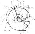
Fig. 1 , a spacecraft with a landing system composed of a number of tethers is shown in the status in which due to high speed rotation of the landing system around the central platform the flexible structure of the landing system is fully deployed by rotation. Reference numeral 1 points to the core spacecraft, consisting of a rigid payload-encapsulating structure or platform, from which emanate flexible tethers of high tensile strength material, ideally Zylon® for the axial tethers and/or gum-metal alloy (Ti-23Nb-0.7Ta-2Zr-1.2O) for the perimetric tethers, shaping a wheel like structure when in rotation. At launch time, the plurality of the flexible tethers (axial and perimetric) need to be wrapped and secured around the core spacecraft (in order to fit in the limited volume under fairing ("New Glenn" at 6.35 meters)) and they are deployed right before touching the lunar surface, by placing the core spacecraft in high spin rate of about 8.62 revolutions per second (for a 30 meter radius). This number of revolutions generates enormous tension on the tethers which only Zylon® so far can sustain (tensile strength 5.81150 MPa, density 5.61.56 g/cm3), or carbon fibers. - Preferably, "gum-metal" is used for the perimeter because it has better properties as regards recycling and reuse. Its wires and ropes can enable the second phase of landing system (MACEDONAS). Another argument for the choice of gum-metal alloy for the perimeter is the low friction coefficient. Gum metal is also suitable for momentum dumping through internal friction in multithreaded core configurations.
- The
numeral 2 depicts the front plane of the flexible structure and the numeral 3 depicts the back plane. Additional planes, parallel to the front and to the back plane may be implemented as required. In thefig.1 numeral 9 indicates a tether that is part of a middle tether plane.Numerals 6 and 7 indicate tethers belonging to the front and back plane respectively.Numerals Numerals -
Numerals 4 indicate tethers that emanate perpendicular to the surface of the core spacecraft, while numeral 5 indicates tethers emanating from adjacent securing locations laterally located at the same supportive ring. Each junction point at the perimeter of the wheel shaped structure is tensioned by a plurality of tethers. Junction points a, b, c, d, define a surface section of the perimeter which will act as the "sole" of the wheel-looking structure. - Preferred dimensions of the depicted embodiment, on which preliminary calculations have been performed, are indicated by numeral 13 (diameter of core spacecraft = 6 m), numeral 14 (length of a perimeter supporting tether = 27 m).
- The individual support tethers will consist of multithreaded Zylon® ropes or similar material to provide the needed tensile support but be flexible enough to permit stowage for the launch.
- The vector of motion with numeral 11 indicates the velocity vector of the lowest point at the perimeter of the flexible structure, the vector with
numeral 12 indicates the velocity vector of the core of the spacecraft. Thevector 15 indicates the direction of rotation.Vectors - In
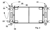
Fig. 2 the core spacecraft is illustrated with two optional service modules. The service modules may be needed to reduce the length of the landing field that is necessary, considering that the rims of the craters hinder the exploitation of the complete swath of the flat areas and reduction of overshooting needs propulsion capability. However, the service modules are not required in all occasions and in particular on flat mare of large size. In the cases where service modules would not be required all the functional elements of the spacecraft shall be embedded in the core spacecraft, otherwise be the payload platform only. - A non-claimed semi rigid configuration is possible, where part of the tethers emanating from the rings could be replaced with rigid or compressible beams. These rigid or compressible beams could initially be folded along the side of the core spacecraft in single or multiple segments each.
- The basic wheel-looking spacecraft can advantageously establish the basis for more complex and efficient configurations of spacecraft. Bicycles, tricycles or 4 wheel vehicles of gargantuan dimensions, could be established. Such spacecraft may become the ideal means of landing on lunar surface, once terrain evening capabilities become possible (beyond the natural flatness). In these cases the deceleration thrusters to achieve the touch down, as well as the payload compartments will not have to be in the volume of the core spacecraft as described in
Fig. 2 but other more advantageous configurations could be established. - The wheels will have to be adapted to higher load-bearing configurations. However the principle of spinning the wheels at such high speed to eliminate the differential friction shall be maintained.
- The following figures show a tether based «parcel capture system».
-
Fig. 3a presents the architecture of a parcel capturing system that can be constructed principally by use of tether segments. The method described is code named "Momentum Absorption of Cargo Express Deliveries Orbiting Non-Atmospheric Somata (MACEDONAS). - Numeral 41 depicts schematically a receptacle, consisting of a vertically hoisted apparatus made of a plurality of wire woven concave surfaces, arranged one inside the other, and all secured at the exterior rim (see 70 at
Fig. 3d ), as successive barriers, of increasing resilience to impact of high velocity objects. The assumed incoming velocity of a parcel is in the range of 1626 m/sec. The receptacle is presented in more detail inFig. 3d, Fig. 3e . andFig. 5a and Fig.5b . -
Numeral 42 depicts a second (final) receptacle where the cargo eventually lands to rest. It shall have the configuration of either a "safety net", similar to the ones used in circuses or in its simplest configuration to consist of just a tether tensioned at some height from the ground by vertical trusses (Fig. 6 numeral 97), and positioned precisely at a distance from the last engagement junction, equal to the length of the last branch plus an offset equal to the length of the tether that precedes the first branch of engagement (Fig 6 . numeral 94). Therefore the length that numerals 94 and 96 ofFig. 6 indicate have to be equal. In the case that a safety net is the configuration of choice it can ideally be placed concentrically to a crater. - Numeral 43 depicts the core tether, which connects to the initial receptacle to the dendritic arrangement of branch tethers.
- Numeral 44 depicts one "branch" tether that emanates from a connection point 43 and is secured to the ground at a "securing" point 46.
- Numeral 45 depicts the ideal (for a flat surface) theoretical limit of the arrangement of the branches, which have been positioned in a way (parabolic curve) not to cross each other once pulled by the central tether.
- Numeral 46 depicts a securing feature on the ground where excess wire is buried under low depth soil, or winded around a conical pile of lunar soil, (screened for stones). This soil, free from stones, can provide soft breaking of the tether once it reaches full tension.
-
Numeral 47 depicts an other attach point, where the core tether is connected to a branch tether. Multiple such connection points along the length of the central tether mechanically engage and accelerate successive branches, as the receptacle with the payload may trip from the initial location towards the final receptacle. The individual tethers are dimensioned, laid and secured in such a way to steer the payload to land at thefinal landing spot 42 with greater positioning accuracy with respect to the initial entry at first receptacle 41. ie apart from momentum damping they act as bias loads to steer the parcel accordingly. - The laying of wire branches is designed in such a way to provide steady and smooth increase in the drag that the receptacle experiences along the trajectory, so that the overall length of the core tether be as minimal as possible.
-
Fig. 3b depicts a modified MACEDONAS in which the first receptacle (51) is not simply hoisted a few meters above ground but is suspended in high altitude by two lifting apparatuses (53). -
Numeral 52 depicts schematically the final receptacle, where the first receptacle with the payload shall come to rest. -
Numeral 54 depicts a connection point between the tether emanating from the lifting apparatus and the perimeter of the receptacle. That connection point is equipped with a quick disconnect (snap off) mechanism based on a brittle material. -
Numeral 55 indicates the core tether. Its length typically consists of the sum of the branched segment (from first branch join to the last branch join) plus the projection of the last branch to the core tether plus the pre-branch lead and it shall be equal to the segment indicated bynumeral 57. -
Numeral 56 indicates that the length may vary. Similarly the numeral 58. However, as stated before the location of the final receptacle shall be at a distance from the last engagement point equal to the sum of the branched segment plus the pre-branch lead (plus the projection of the last branch to the core tether). The system therefore is adaptable to catching payloads from different altitudes with dynamic positioning of the first receptacle. The more ISRU activities take place and volatiles are collected such volatiles (of almost any kind) can be used to propel apparatuses that would lift the receptacle at significant altitudes, therefore requiring less fuel to reach the rendezvous (with the receptacle) point. -
Fig. 3c depicts from lateral perspective the MACEDONAS system presented inFig. 3b . -
Numeral 61 depicts schematically the receptacle (for more detail seeFig. 3d and Fig. 3e as well asFig. 5a ). -
Numeral 62 depicts the lifting apparatuses. Preferably operating on pressurized volatiles harvested locally (ISRU). -
Numeral 63 depicts the core tether. -
Numeral 64 indicates the height of which the receptacle has been lifted -
Numeral 65 depicts the dendritic part of the MACEDONAS. -
Numeral 66 indicates the distance of the final receptacle from the end of the dendritic system. (Note: the end of the dendritic system is at the point where the last branch can reach, ie it is at a distance from the last connection point equal to the projection of the last branch on the core tether). -
Numeral 67 indicates the final receptacle. -
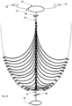
Fig. 3d depicts the first receptacle from side view andFig. 3e depicts the same at a front view. -
Numeral 70 indicates the rim of the first concave surface of the receptacle, on which rim actually are connected also the rims of the embedded concave surfaces. In this way the momentum from the parcel is transferred to the rim and through the anchor point (79) to the core tether. -
Numeral 71 depicts the connection points for the lifting / hoisting of the receptacle. It is advantageously equipped with a quick disconnect (snap off) mounting (glass hook possibly or other brittle material). -
Numeral 72 indicates the length of the receptacle whole -
Numeral 73 indicates a tether segment used for suspension of the receptacle. -
Numeral 74 indicates a truss for securing a tether that suspends the receptacle. -
Numeral 75 indicates the width of the rim -
Numeral 76 indicates the height of the rim. -
Numerals 77 indicate the volumes between successive concave surfaces. It can be any of the four a) void, b) filled with compacted mixture of clay and slit, c) filled by a pre-shaped closed-cell ceramic foam, or d) antiballistic fabric, or a combination of the a,b,c,d depending on how much shock a parcel can sustain. -
Numeral 79 indicates the anchor point where the core tether is secured. -
Fig. 5a depicts the receptacle as it is before receiving a parcel andFig. 5b depicts the same as after receiving a parcel, in which case all but one of the concave surfaces have been perforated and only the external restrains the parcel from escaping. In this multi concave configuration the momentum loss of the parcel (& its transfer to the anchor point (79), needed to accelerate the receptacle, is advantageously divided in 8 steps, therefore the sock impact on the parcel is also advantageously reduced significantly (other number of barriers can be deviced according to specific needs). In any case it is assumed that in the beginning the commodity available for shaping the receptacle is none other than ropes from Zylon® and wir-eof gum-metal by which the concave surfaces are woven. Derivative configurations may become possible at later stages, with the use of composite material. -
Numeral 50 indicates a unit of parcel. It is schematically being presented as spherical. This implies that it will constitute a passive unit of parcel to be delivered to the receptacle entrance at the right velocity and angle form an over-orbiting delivery spacecraft (OODS). That is simple to achieve even with a mechanical ejector that will eject such unit parcel at the direction opposite to the motion of the OODS, so that the unit payload loses part of its kinetic energy and altitude. The timing though of such injection is of high importance and corresponding calculations will have to be performed for each parcel drop as the orbit of the OODS will also be affected by each parcel ejection. -
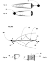
Figures 4a to 4e depict successive instances in time of the parcel momentum absorption. InFig. 4a is depicted the instance just prior to the entry of the parcel (82 (indicated with numeral 50 inFig 5 )) at the rim of the receptacle (80). -
Fig. 4b depicts the parcel having perforated the first 7 concave surfaces and be captured by the final (and most robust) external concave surface. -
Fig. 4c depicts the receptacle detached & dispatched from its "anchoring" location and be propelled along a trajectory (83) indicated by the dotted "constrained ballistic trajectory". Note: it is not pure ballistic trajectory but constrained ballistic trajectory, constrained by the mechanics of the core tether and the dendritic tether system. At this moment 6 nodes of wire branches have been engaged (lifted) and add drag to the progression of the parcel carrying receptacle. -
Fig. 4d depicts the receptacle at the moment it has progressed that much that all 13 nodes of wire branches have been engaged (lifted) (but not fully stretched the corresponding wire/rope branches). -
Fig. 4e depicts the receptacle at the moment it has progressed that much that has engaged all joints to the wire/rope branches and has stretched them to their maximum length. By that time, (if the initial configuration of the MACEDONAS, as regards the individual elements of the system (number of branches and dimensions, terrain considerations etc)) where correct, the receptacle must have zero remaining momentum and shall land safely on the final receptacle (87 inFig. 4e , or 81 inFig. 4a ) - The system is rather versatile as regards accepting parcels of different masses. In the schematics we use dendritic systems of 13 nodes but this can be altered at will. The length of the dendritic system, the length of the branches and their initial layout, as well as the thickness of the wire/rope tethers are all configurable parameters. Further, repeatability, with the exception of the first receptacle that will need to be replaced after each mission (and recycled), all other elements can be put back in place for the next mission in a matter of minutes, by pulling the anchor point/the core tether start back to the initial "anchor" location. The branches of the dendritic system will be laid naturally to their initial configuration (provided the soil does not hinder their motion).
-
Fig. 6a depicts from top view, a final receptacle made of two trusses and horizontal wires, at the instance where the first receptacle has reached its destination.Fig. 6b is a side view of the receptacle hanging at the end receptacle at some distance from the ground.Fig. 6c front view depicting the horizontal to the ground wires/ropes, connecting the trusses, for limiting the first receptacle to loop around the top wire. - Further, the following components are shown:
- 90 height of last receptacle with respect to the local terrain (at last receptacle spot)
- 91 Start shape of first branch
- 92 End shape of first branch
- 93 First note of wire branch engagement
- 94 Lead length of core tether before first node of wire branch engagement
- 95 distance of final receptacle from final engagement node of initial state dendritic system.
- 96 First receptacle at rest at last receptacle
- 97 two trusses for tensioning wire tether to act as second receptacle
- 98 top wire (bears the weight)
- 99 other than top wires to constrain receptacle from looping around top wire.
Claims (3)
- Landing system for a spacecraft, with a foldable tether-based carrier structure configured to unfold when rotating and to assume a wheel-type shape supporting in its center a rigid carrier platform for a payload, wherein the tether-based carrier structure comprises a number of tethers each emanating from the rigid carrier platform, characterised in that the tether-based carrier structure comprises a number of perimetric tethers which, when in rotation, shape the outer circumference of a wheel like structure.
- Landing system according to claim 1, in which the perimetric tethers are made from gum-metal alloy, in particular Ti-23Nb-0.7Ta-2Zr-1.2O.
- Use of the landing system according to claim 1 or 2 to assemble a catching system for a high velocity orbiting object, wherein the catching system is constructed by scavenging material from the landing system.
Priority Applications (2)
| Application Number | Priority Date | Filing Date | Title |
|---|---|---|---|
| EP21165077.5A EP4063281B1 (en) | 2021-03-25 | 2021-03-25 | Two phase landing system for the moon and its implementation elements |
| PCT/EP2022/057971 WO2022200596A1 (en) | 2021-03-25 | 2022-03-25 | Two phase landing system for the moon and its implementation elements |
Applications Claiming Priority (1)
| Application Number | Priority Date | Filing Date | Title |
|---|---|---|---|
| EP21165077.5A EP4063281B1 (en) | 2021-03-25 | 2021-03-25 | Two phase landing system for the moon and its implementation elements |
Publications (3)
| Publication Number | Publication Date |
|---|---|
| EP4063281A1 EP4063281A1 (en) | 2022-09-28 |
| EP4063281B1 true EP4063281B1 (en) | 2023-11-29 |
| EP4063281C0 EP4063281C0 (en) | 2023-11-29 |
Family
ID=75252330
Family Applications (1)
| Application Number | Title | Priority Date | Filing Date |
|---|---|---|---|
| EP21165077.5A Active EP4063281B1 (en) | 2021-03-25 | 2021-03-25 | Two phase landing system for the moon and its implementation elements |
Country Status (2)
| Country | Link |
|---|---|
| EP (1) | EP4063281B1 (en) |
| WO (1) | WO2022200596A1 (en) |
Family Cites Families (6)
| Publication number | Priority date | Publication date | Assignee | Title |
|---|---|---|---|---|
| US6565044B1 (en) * | 2002-03-14 | 2003-05-20 | The United States Of America As Represented By The Administrator Of The National Aeronautics And Space Administration | Combination solar sail and electrodynamic tether propulsion system |
| US20080099624A1 (en) * | 2006-10-16 | 2008-05-01 | Erik Evjenth | Space tether transport system |
| CN105783610B (en) * | 2016-03-14 | 2017-05-10 | 门德君 | Ocean rocket recovery device |
| CN106347716B (en) * | 2016-09-29 | 2018-08-21 | 西北工业大学 | A kind of gyroscope type energy conversion device and method for space articulation |
| WO2019135786A1 (en) * | 2017-06-22 | 2019-07-11 | Lenard Roger X | Zero and fractional g sample and resource collection, transport and archiving |
| CN110185732B (en) * | 2019-06-03 | 2022-01-18 | 哈尔滨工业大学 | Linear electromagnetic damping device for spacecraft recovery |
-
2021
- 2021-03-25 EP EP21165077.5A patent/EP4063281B1/en active Active
-
2022
- 2022-03-25 WO PCT/EP2022/057971 patent/WO2022200596A1/en active Application Filing
Also Published As
| Publication number | Publication date |
|---|---|
| EP4063281C0 (en) | 2023-11-29 |
| WO2022200596A1 (en) | 2022-09-29 |
| EP4063281A1 (en) | 2022-09-28 |
Similar Documents
| Publication | Publication Date | Title |
|---|---|---|
| JP6458956B2 (en) | Rocket transport devices used in rocket launch systems | |
| CA2677942C (en) | Space elevator | |
| US7131613B2 (en) | High-altitude launching of rockets lifted by helium devices and platforms with rotatable wings | |
| JPH10505560A (en) | Reusable launch platform and reusable spacecraft | |
| CN102438906A (en) | Landing device for a space probe, and landing method for a probe provided with such a device | |
| US11014692B2 (en) | Elevated load-bearing platform | |
| CN102939239A (en) | Airborne elevator apparatus | |
| RU2735441C1 (en) | Space elevator for delivery of passengers and cargoes from surface of earth or other planet to low orbit and back and method of construction thereof | |
| US20080099624A1 (en) | Space tether transport system | |
| EP4063281B1 (en) | Two phase landing system for the moon and its implementation elements | |
| RU2344973C1 (en) | Earth-lunar facility (elf) | |
| CA2998180C (en) | Launch system apparatus | |
| CN113195362B (en) | Global transport system and method for placing payloads in circular orbit | |
| CN111977029A (en) | Multipurpose transmission system and construction scheme thereof | |
| BIRCH | ORBITAL RING SYSTEMS AND JACOB'5 LADDERS*'ll | |
| Ishikawa | Space Elevator for Space-Resource Mining | |
| Hypes et al. | Concepts for manned lunar habitats | |
| CN111038736A (en) | Spacecraft slow-speed high-throwing type launching method and launching platform | |
| Arnold et al. | IN THE LEO-MOON SYSTEM | |
| Arnold et al. | ADVANCED PROPUI ION FOR LEO-MOON TRANSPORT: II. TETHER CONFIGURATIONS IN LEO-MOON SYSTEM | |
| Baker et al. | Lunar and mars mission architecture utilizing tether-launched LLOX | |
| BIRCH | A method of transferring payloads into space without using rockets has been presented in Part I, in which massive rings encircle the globe in a low orbit supporting stationary" sky-hooks," from which cables hang down to any point on the Earth's surface. Vehicles can climb up these “ladders' into orbit, or can accelerate along the rings. The structure and | |
| Arnold | ADVANCED PROPULSION FOR LEO-MOON TRANSPORT: II. TEIBER CONFIGURATIONS IN TllE LEO-MOON SYSTEM | |
| Barcelo et al. | Space Tethers: Applications and Implementations | |
| Sparks | Analysis of Space Elevator Technology |
Legal Events
| Date | Code | Title | Description |
|---|---|---|---|
| PUAI | Public reference made under article 153(3) epc to a published international application that has entered the european phase |
Free format text: ORIGINAL CODE: 0009012 |
|
| STAA | Information on the status of an ep patent application or granted ep patent |
Free format text: STATUS: THE APPLICATION HAS BEEN PUBLISHED |
|
| AK | Designated contracting states |
Kind code of ref document: A1 Designated state(s): AL AT BE BG CH CY CZ DE DK EE ES FI FR GB GR HR HU IE IS IT LI LT LU LV MC MK MT NL NO PL PT RO RS SE SI SK SM TR |
|
| STAA | Information on the status of an ep patent application or granted ep patent |
Free format text: STATUS: REQUEST FOR EXAMINATION WAS MADE |
|
| 17P | Request for examination filed |
Effective date: 20230328 |
|
| RBV | Designated contracting states (corrected) |
Designated state(s): AL AT BE BG CH CY CZ DE DK EE ES FI FR GB GR HR HU IE IS IT LI LT LU LV MC MK MT NL NO PL PT RO RS SE SI SK SM TR |
|
| GRAP | Despatch of communication of intention to grant a patent |
Free format text: ORIGINAL CODE: EPIDOSNIGR1 |
|
| STAA | Information on the status of an ep patent application or granted ep patent |
Free format text: STATUS: GRANT OF PATENT IS INTENDED |
|
| RIC1 | Information provided on ipc code assigned before grant |
Ipc: B64G 1/10 20060101ALN20230522BHEP Ipc: B64G 99/00 20090101ALI20230522BHEP Ipc: B64G 1/64 20060101ALI20230522BHEP Ipc: B64G 1/62 20060101AFI20230522BHEP |
|
| RIC1 | Information provided on ipc code assigned before grant |
Ipc: B64G 1/10 20060101ALN20230530BHEP Ipc: B64G 99/00 20090101ALI20230530BHEP Ipc: B64G 1/64 20060101ALI20230530BHEP Ipc: B64G 1/62 20060101AFI20230530BHEP |
|
| INTG | Intention to grant announced |
Effective date: 20230621 |
|
| GRAS | Grant fee paid |
Free format text: ORIGINAL CODE: EPIDOSNIGR3 |
|
| GRAA | (expected) grant |
Free format text: ORIGINAL CODE: 0009210 |
|
| STAA | Information on the status of an ep patent application or granted ep patent |
Free format text: STATUS: THE PATENT HAS BEEN GRANTED |
|
| AK | Designated contracting states |
Kind code of ref document: B1 Designated state(s): AL AT BE BG CH CY CZ DE DK EE ES FI FR GB GR HR HU IE IS IT LI LT LU LV MC MK MT NL NO PL PT RO RS SE SI SK SM TR |
|
| REG | Reference to a national code |
Ref country code: GB Ref legal event code: FG4D |
|
| REG | Reference to a national code |
Ref country code: CH Ref legal event code: EP |
|
| REG | Reference to a national code |
Ref country code: DE Ref legal event code: R096 Ref document number: 602021007161 Country of ref document: DE |
|
| REG | Reference to a national code |
Ref country code: IE Ref legal event code: FG4D |
|
| U01 | Request for unitary effect filed |
Effective date: 20231229 |
|
| U07 | Unitary effect registered |
Designated state(s): AT BE BG DE DK EE FI FR IT LT LU LV MT NL PT SE SI Effective date: 20240111 |
|
| PG25 | Lapsed in a contracting state [announced via postgrant information from national office to epo] |
Ref country code: GR Free format text: LAPSE BECAUSE OF FAILURE TO SUBMIT A TRANSLATION OF THE DESCRIPTION OR TO PAY THE FEE WITHIN THE PRESCRIBED TIME-LIMIT Effective date: 20240301 |
|
| PG25 | Lapsed in a contracting state [announced via postgrant information from national office to epo] |
Ref country code: IS Free format text: LAPSE BECAUSE OF FAILURE TO SUBMIT A TRANSLATION OF THE DESCRIPTION OR TO PAY THE FEE WITHIN THE PRESCRIBED TIME-LIMIT Effective date: 20240329 |
|
| PG25 | Lapsed in a contracting state [announced via postgrant information from national office to epo] |
Ref country code: ES Free format text: LAPSE BECAUSE OF FAILURE TO SUBMIT A TRANSLATION OF THE DESCRIPTION OR TO PAY THE FEE WITHIN THE PRESCRIBED TIME-LIMIT Effective date: 20231129 |
|
| PG25 | Lapsed in a contracting state [announced via postgrant information from national office to epo] |
Ref country code: IS Free format text: LAPSE BECAUSE OF FAILURE TO SUBMIT A TRANSLATION OF THE DESCRIPTION OR TO PAY THE FEE WITHIN THE PRESCRIBED TIME-LIMIT Effective date: 20240329 Ref country code: GR Free format text: LAPSE BECAUSE OF FAILURE TO SUBMIT A TRANSLATION OF THE DESCRIPTION OR TO PAY THE FEE WITHIN THE PRESCRIBED TIME-LIMIT Effective date: 20240301 Ref country code: ES Free format text: LAPSE BECAUSE OF FAILURE TO SUBMIT A TRANSLATION OF THE DESCRIPTION OR TO PAY THE FEE WITHIN THE PRESCRIBED TIME-LIMIT Effective date: 20231129 |
|
| U20 | Renewal fee paid [unitary effect] |
Year of fee payment: 4 Effective date: 20240331 |