EP4063254A1 - Smart buoy - Google Patents
Smart buoy Download PDFInfo
- Publication number
- EP4063254A1 EP4063254A1 EP22159133.2A EP22159133A EP4063254A1 EP 4063254 A1 EP4063254 A1 EP 4063254A1 EP 22159133 A EP22159133 A EP 22159133A EP 4063254 A1 EP4063254 A1 EP 4063254A1
- Authority
- EP
- European Patent Office
- Prior art keywords
- buoy
- floating body
- watercraft
- identification information
- electronic unit
- Prior art date
- Legal status (The legal status is an assumption and is not a legal conclusion. Google has not performed a legal analysis and makes no representation as to the accuracy of the status listed.)
- Withdrawn
Links
Images
Classifications
-
- B—PERFORMING OPERATIONS; TRANSPORTING
- B63—SHIPS OR OTHER WATERBORNE VESSELS; RELATED EQUIPMENT
- B63B—SHIPS OR OTHER WATERBORNE VESSELS; EQUIPMENT FOR SHIPPING
- B63B22/00—Buoys
- B63B22/02—Buoys specially adapted for mooring a vessel
-
- B—PERFORMING OPERATIONS; TRANSPORTING
- B63—SHIPS OR OTHER WATERBORNE VESSELS; RELATED EQUIPMENT
- B63B—SHIPS OR OTHER WATERBORNE VESSELS; EQUIPMENT FOR SHIPPING
- B63B22/00—Buoys
- B63B2022/006—Buoys specially adapted for measuring or watch purposes
Definitions
- the invention relates to a buoy for attaching watercraft, which is provided with a floating body and an electronic unit with a transmitter for wireless data transmission and with photovoltaic elements for powering the electronic unit, the floating body being in an occupied state when the watercraft is attached and when it is absent of a fixed watercraft in an unoccupied state, according to the preamble of claim 1.
- the invention further relates to a method for monitoring the occupancy state of buoys of a buoy field with a buoy according to the invention, according to the preamble of claim 8.
- Buoy fields are used by watercraft to temporarily secure the watercraft and generally include a plurality of buoys that are anchored at a distance from one another on the lake or seabed near the shore.
- the watercraft can be attached to a fastening device of the buoy using a line.
- a fee has to be paid for the use of a buoy.
- the procedure is usually such that the watercraft approaches the buoy field, searches for a free buoy and moors at the free buoy. Subsequently, either a registration office on land must be visited in order to report the mooring and pay the fee, or the operator of the buoy field visits the watercraft by boat to record the vehicle data and collect the fee.
- the aim of the invention is therefore, on the one hand, to enable simple management of a buoy field with little personnel effort and, on the other hand, to be able to discover and thus penalize unauthorized occupancy of a buoy.
- Claim 1 relates to a buoy for attaching watercraft, which is provided with a floating body and an electronic unit with a transmitter for wireless data transmission and with photovoltaic elements for powering the electronic unit, the floating body being in an occupied state when the watercraft is attached and in the absence of an attached vessel in an unoccupied condition.
- the floating body is provided with an acceleration sensor for measuring acceleration data for the floating body, and the acceleration sensor is connected to an evaluation unit of the electronic unit, which is designed to separate the acceleration data measured by the acceleration sensor when it is unoccupied from the acceleration data when it is occupied measured acceleration data.
- a buoy is thus realized which can determine the occupancy status autonomously.
- This determination of the occupancy state is carried out using an acceleration sensor, since the applicant has found that it is easily possible to distinguish between an unoccupied state and an occupied state of the buoy using the measured acceleration data.
- This distinction is made, for example, with the help of the detection of acceleration peaks caused by a watercraft attached to the buoy because the watercraft attached to the buoy repeatedly tears and tugs at the buoy. Comparable acceleration peaks do not occur with an unoccupied buoy floating in the water and can therefore be used to reliably distinguish between occupied and unoccupied states.
- An appropriately configured evaluation unit A 9-axis acceleration sensor with three three-axis sensors can be used as the acceleration sensor be, namely an acceleration sensor, a gyroscope and a geomagnetic sensor. These three sensors ensure that extremely accurate acceleration data for acceleration, angular rate and earth's magnetic field can be determined, whereby such sensors can be optimized for the best performance with the lowest power consumption.
- occupancy state information The information about an occupied or unoccupied state of a buoy is also referred to below as occupancy state information.
- occupancy state information The information about an occupied or unoccupied state of a buoy is also referred to below as occupancy state information.
- the transmission device can be sent together with buoy identification information identifying the buoy to a central monitoring unit, where it is compared, for example, with corresponding reservation information for the relevant buoy.
- This transmission of the occupancy status information can be initiated autonomously by the buoy, for example when there is a change in the occupancy status information.
- the occupancy status information is initially only stored in a data memory of the buoy and is only called up by the central monitoring unit when required.
- the transmission device is designed as part of a network connection for the bidirectional exchange of data.
- the transmission device is designed as a network connection for a wide area network, for example as NB-IoT (Narrow Band Internet-of-Things), which is a "Low Power Wide Area (LPWA)" radio technology with low energy requirements and a long range for the bidirectional transmission of small data packets.
- NB-IoT Near Band Internet-of-Things
- LPWA Low Power Wide Area
- this Reservation information is transmitted to the buoy and is displayed accordingly on the buoy.
- the floating body is provided with a lighting means that can be activated via the network connection.
- the buoy can thus be marked as reserved for the watercraft by the central monitoring unit, for example by activating a red light, and as available by activating a green light, for example.
- the floating body is provided with an inductive sensor for detecting conductive or ferromagnetic objects.
- An inductive sensor detects the presence of conductive or ferromagnetic objects, particularly metal objects, by changing a magnetic field in the vicinity of such an object.
- the arrangement of such a sensor enables the detection of metallic components of a watercraft, for example its anchor or its engine block, and can be used to supplement the acceleration data in order to optimize the detection of an occupied state and in particular to detect double occupancy of a buoy, i.e the presence of a second vessel improperly attached to the same buoy.
- a specific embodiment of the buoy preferably provides that the floating body is formed by a lower floating body part that is rotationally symmetrical about a longitudinal axis of the floating body and an upper functional body part, with the functional body part having an outer surface that is at least partially formed from planar partial surfaces.
- the planar sub-areas can be used, for example, for the arrangement of photovoltaic elements in order to facilitate their attachment to the floating body and to optimize their positioning with regard to maximum power generation. However, they can also be used to facilitate removal of the electronic unit for maintenance or repair purposes. For this purpose, it is proposed in particular that the electronic unit is arranged in a housing that is embedded in the floating body and on a planar face is arranged adjacent. The electronic unit can thus be found easily if required, for example by also marking the corresponding planar sub-area accordingly, and subsequently also easily removed by providing access to the electronic unit via the covering sub-area.
- the floating body is provided with a short-range radio transmitter for the wireless transmission of buoy identification information identifying the buoy.
- the short-range radio transmitter is based, for example, on "Bluetooth Low Energy (BLE)" technology, with which data can be exchanged with other devices within a limited radius of 10-100 m. The power consumption can be kept very low.
- BLE Bluetooth Low Energy
- the invention also relates to a method for monitoring the occupancy status of buoys in a field of buoys with a buoy according to the invention, it being proposed that the evaluation unit of the electronic unit of the buoy identify the occupancy status of the relevant buoy using the acceleration sensor as an unoccupied status or as an occupied status , and this occupancy status information is sent together with a buoy identification information identifying the buoy via the transmitting device to a central monitoring unit.
- the occupancy status information can be compared with corresponding reservation information for the relevant buoy. If occupancy of the buoy is detected but no reservation information is available, a warning message can be generated in order to indicate to the operator of the buoy field an unauthorized occupancy of a buoy.
- the location of each buoy is known, for example by each buoy being provided with a GPS sensor which carries out an exact determination of the position of the relevant buoy.
- a corresponding monitoring and reservation system could be designed in such a way that user-specific operating software (e.g. as an "application” or “app”) is provided for mobile devices, via which an interested party can reserve a specific buoy for a buoy field of his choice and sometimes pay immediately can.
- the mobile radio terminal can be a mobile phone (“smartphone”), for example, or a tablet, a laptop, or any other device equipped with a router or gateway that can set up and use mobile radio connections.
- the reservation for a specific buoy is sent via the cellular connection to the central monitoring unit, where it is stored and used as reservation information, for example by activating a lamp arranged on the relevant buoy accordingly.
- the buoy identification information can be retrieved from the mobile radio terminal via a short-range radio transmitter of the buoy when a mobile radio terminal equipped with a short-range radio interface for receiving the buoy identification information is present in the transmission range of the short-range radio transmitter .
- the buoy identification information is sent from the mobile radio terminal via a mobile radio connection together with watercraft identification information that identifies the watercraft to the central monitoring unit, with the central monitoring unit using the buoy identification information to link the watercraft identification information to the occupancy status information in terms of data technology. It is thus possible to check whether the buoy is occupied and whether there is a reservation for this buoy, and whether the watercraft for which the reservation was made is at the correct buoy.
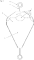
- FIG. 1 shows an embodiment of a buoy according to the invention with a rotationally symmetrical lower floating body part 1 and an upper functional body part 2, with the upper functional body part 2 covering the lower floating body part 1 in the manner of a hood and in a lower peripheral area tightly encompassing the upper peripheral area of the floating body part 1.
- Both parts consist of a laminated carbon fleece, i.e. a fleece made of carbon fibers, which is bonded with an epoxy resin.
- the interior of the floating body part 1 and the functional body part 2 are filled with polyurethane foam.
- the float portion 1 is frusto-conical about a longitudinal axis of the buoy defined by a stainless rod 3 crossing the buoy.
- the rod 3 has an eyelet at each of its upper and lower ends.
- the upper eyelet serves as a fastening device 4 for fastening the watercraft, and the lower eyelet serves for fastening to the underwater. After filling with the polyurethane foam, the lower floating body part 1 and the upper functional body part 2 together form the floating body of the buoy.
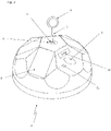
- the upper functional body part 2 has an outer surface which is at least partially formed from planar partial surfaces 5, such as in particular 2 can be removed.
- a top planar partial surface 5 also carries a shim 6 a nut 7, which serves to attach the rod 4.
- Photovoltaic elements 8 distributed around the circumference of the outer surface of the functional body part 2 are fastened to four of the planar partial surfaces 5 for generating electricity.
- On a further planar partial surface 5 there is a marking 9 and an access possibility to an underlying electronic unit in order to facilitate locating and accessing the electronic unit for maintenance or repair purposes.
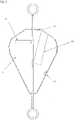
- the 3 shows the buoy according to 1 with an illustration of some internal components.
- the floating body part 1 and the functional body part 2 are filled with polyurethane foam, which ensures the tightness of the arrangement and serves as protection for the sensors and electronics embedded therein.
- a tubular housing 12 is placed so that it opens against a planar part surface 5 .
- the electronic unit can then be arranged in this housing 12, as will be explained in more detail below.
- an additional power source 13 is arranged, which converts kinetic energy of the buoy into electricity by shaking induction.
- the 3 two more temperature sensors 14, 15 can be removed.
- a lower temperature sensor 15 is used to determine the water temperature.
- An upper temperature sensor 14 is used to determine the air temperature.
- the photovoltaic elements 8 and the temperature sensors 14, 15 are connected to a printed circuit board of the electronic unit, which is arranged inside the housing 12.
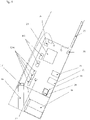
- the 4 shows a possible embodiment of such an electronic unit.
- the electronic unit has a circuit board which is initially connected to a power storage device 16 which supplies the electronic unit with power.
- the power storage 16 is of the photovoltaic elements 8 and the additional power source 13 charged via a charge controller 27.
- the electronic unit includes a GPS sensor 17, which is arranged on a support 18 and is used to determine the exact position of the buoy.
- An SD card slot 22 for local data storage and a slot 23 for a SIM card are also provided.
- the network connection 24 is provided by a modem and implemented, for example, as NB-IoT, which is an LPWA radio technology with a low energy requirement and a long range for the bidirectional transmission of small data packets.
- the circuit board is wired to an antenna as a transmission device 25, which is attached to the wall of the buoy, for example by means of adhesive strips.
- the circuit board of the electronic unit is also provided with an acceleration sensor 26, which can be designed, for example, as a 9-axis acceleration sensor with three three-axis sensors, namely an acceleration sensor, a gyroscope and a geomagnetic sensor. These three sensors ensure that extremely accurate acceleration data for acceleration, angular rate and earth's magnetic field can be determined, whereby such sensors can be optimized for the best performance with the lowest power consumption.
- the electronic unit is provided with an inductive sensor 28 for detecting conductive or ferromagnetic objects.
- an inductive sensor 28 enables the detection of metallic components of a watercraft, for example its anchor or its engine block, and can be used to supplement the acceleration data in order to optimize the detection of an occupied condition and in particular a To detect double occupancy of a buoy, i.e. the presence of a second watercraft that is illegally attached to the same buoy.
- the in the Figures 1-4 The buoy shown could be used in a monitoring and reservation system in which, for example, user-specific operating software (e.g. as an "application” or “app”) is provided for mobile radio terminals, via which an interested party can reserve a specific buoy for a buoy field of his choice and sometimes also can pay immediately.
- the mobile radio terminal can be a cell phone ("smartphone"), for example.
- the reservation for a specific buoy is made via the cellular connection to the central monitoring unit (in the Figures 1-4 not visible), where it is stored as reservation information and utilized by activating the lighting means 11 arranged on the relevant buoy accordingly.
- the boatman can register either via Bluetooth or using the buoy number, which can be entered in the app, whereupon the watercraft identification information can be compared with the buoy identification information with the Occupancy status information is linked in terms of data technology and the buoy in question is stored with the status "occupied”. It can also be checked whether the buoy is occupied and whether there is a reservation for this buoy, and whether the watercraft for which the reservation was made is at the correct buoy.
Abstract
Boje zur Befestigung von Wasserfahrzeugen, die mit einem Schwimmkörper und einer elektronischen Einheit mit einer Sendeeinrichtung (25) zur drahtlosen Datenübermittlung sowie mit Photovoltaikelementen (8) zur Stromversorgung der elektronischen Einheit versehen ist, wobei sich der Schwimmkörper bei befestigtem Wasserfahrzeug in einem belegten Zustand befindet und bei Abwesenheit eines befestigten Wasserfahrzeuges in einem unbelegten Zustand. Es wird vorgeschlagen, dass der Schwimmkörper mit einem Beschleunigungssensor (26) zum Messen von Beschleunigungsdaten für den Schwimmkörper versehen ist, und der Beschleunigungssensor (26) mit einer Auswerteeinheit (21) der elektronischen Einheit verbunden ist, die ausgelegt ist um die vom Beschleunigungssensor (26) bei unbelegtem Zustand gemessenen Beschleunigungsdaten von den bei belegtem Zustand gemessenen Beschleunigungsdaten zu unterscheiden. Ferner wird ein Verfahren zur Überwachung des Belegungszustandes von Bojen eines Bojenfeldes vorgeschlagen.

Description
Die Erfindung betrifft eine Boje zur Befestigung von Wasserfahrzeugen, die mit einem Schwimmkörper und einer elektronischen Einheit mit einer Sendeeinrichtung zur drahtlosen Datenübermittlung sowie mit Photovoltaikelementen zur Stromversorgung der elektronischen Einheit versehen ist, wobei sich der Schwimmkörper bei befestigtem Wasserfahrzeug in einem belegten Zustand befindet und bei Abwesenheit eines befestigten Wasserfahrzeuges in einem unbelegten Zustand, gemäß dem Oberbegriff von Anspruch 1. Die Erfindung bezieht sich des Weiteren auf ein Verfahren zur Überwachung des Belegungszustandes von Bojen eines Bojenfeldes mit einer erfindungsgemäßen Boje, gemäß dem Oberbegriff von Anspruch 8.The invention relates to a buoy for attaching watercraft, which is provided with a floating body and an electronic unit with a transmitter for wireless data transmission and with photovoltaic elements for powering the electronic unit, the floating body being in an occupied state when the watercraft is attached and when it is absent of a fixed watercraft in an unoccupied state, according to the preamble of
Bojenfelder dienen Wasserfahrzeugen zur vorübergehenden Befestigung der Wasserfahrzeuge und umfassen in der Regel eine Mehrzahl an Bojen, die voneinander beabstandet in Ufernähe am See- oder Meeresgrund verankert sind. Das Wasserfahrzeug kann dabei mithilfe einer Leine an einer Befestigungsvorrichtung der Boje befestigt werden. Üblicherweise muss für die Benutzung einer Boje eine Gebühr entrichtet werden. Hierfür wird in der Regel so verfahren, dass das Wasserfahrzeug das Bojenfeld anfährt, eine freie Boje sucht und an der freien Boje anlegt. In weiterer Folge muss entweder eine Anmeldestelle an Land aufgesucht werden, um das Anlegen zu melden und die Gebühr zu entrichten, oder das Wasserfahrzeug wird vom Betreiber des Bojenfeldes per Boot aufgesucht, um die Fahrzeugdaten zu erfassen und die Gebühr einzuheben. Diese Vorgänge sind für die Beteiligten mühsam und zeitaufwändig. In der Praxis stellt sich zudem immer wieder das Problem, dass Wasserfahrzeuge am Tagesende ein Bojenfeld aufsuchen wollen, aber keine freie Boje mehr verfügbar ist, oder ein Wetteifern um die letzten verbliebenen Bojen einsetzt. Daher wurden bereits Reservierungssysteme vorgeschlagen, bei denen mithilfe eines Mobilfunkendgeräts ("Smartphone") eine Boje reserviert und mitunter auch sofort bezahlt werden kann. Dadurch kann der Aufwand der personellen Abwicklung von Anmeldung und Bezahlung reduziert und theoretisch auch gänzlich vermieden werden, allerdings steigt dadurch die Gefahr von Missbrauch, indem Bojen belegt aber nicht bezahlt werden.Buoy fields are used by watercraft to temporarily secure the watercraft and generally include a plurality of buoys that are anchored at a distance from one another on the lake or seabed near the shore. The watercraft can be attached to a fastening device of the buoy using a line. Usually a fee has to be paid for the use of a buoy. For this purpose, the procedure is usually such that the watercraft approaches the buoy field, searches for a free buoy and moors at the free buoy. Subsequently, either a registration office on land must be visited in order to report the mooring and pay the fee, or the operator of the buoy field visits the watercraft by boat to record the vehicle data and collect the fee. These operations are tedious and time-consuming for those involved. In practice, there is also always the problem that watercraft want to visit a buoy field at the end of the day, but there are no more free buoys available, or there is competition for the last remaining buoys. Reservation systems have therefore already been proposed in which a buoy can be reserved and sometimes also paid for immediately using a mobile radio terminal (“smartphone”). As a result, the effort involved in handling registration and payment can be reduced and theoretically avoided entirely, but this increases the risk of misuse by buoys being occupied but not paid for.
Es besteht daher das Ziel der Erfindung darin, einerseits eine einfache Verwaltung eines Bojenfeldes mit einem geringen personellen Aufwand zu ermöglichen, und andererseits unautorisierte Belegungen einer Boje zu entdecken und somit ahnden zu können.The aim of the invention is therefore, on the one hand, to enable simple management of a buoy field with little personnel effort and, on the other hand, to be able to discover and thus penalize unauthorized occupancy of a buoy.
Diese Ziele werden durch die Merkmale von Anspruch 1 erreicht. Anspruch 1 bezieht sich auf eine Boje zur Befestigung von Wasserfahrzeugen, die mit einem Schwimmkörper und einer elektronischen Einheit mit einer Sendeeinrichtung zur drahtlosen Datenübermittlung sowie mit Photovoltaikelementen zur Stromversorgung der elektronischen Einheit versehen ist, wobei sich der Schwimmkörper bei befestigtem Wasserfahrzeug in einem belegten Zustand befindet und bei Abwesenheit eines befestigten Wasserfahrzeuges in einem unbelegten Zustand. Erfindungsgemäß wird hierbei vorgeschlagen, dass der Schwimmkörper mit einem Beschleunigungssensor zum Messen von Beschleunigungsdaten für den Schwimmkörper versehen ist, und der Beschleunigungssensor mit einer Auswerteeinheit der elektronischen Einheit verbunden ist, die ausgelegt ist um die vom Beschleunigungssensor bei unbelegtem Zustand gemessenen Beschleunigungsdaten von den bei belegtem Zustand gemessenen Beschleunigungsdaten zu unterscheiden. Erfindungsgemäß wird somit eine Boje verwirklicht, die den Belegungszustand autonom ermitteln kann. Diese Ermittlung des Belegungszustandes erfolgt mithilfe eines Beschleunigungssensors, da die Anmelderin festgestellt hat, dass es anhand der gemessenen Beschleunigungsdaten leicht möglich ist einen unbelegten Zustand von einem belegten Zustand der Boje zu unterscheiden. Diese Unterscheidung erfolgt beispielsweise mithilfe der Detektion von Beschleunigungsspitzen, die von einem an der Boje befestigten Wasserfahrzeug verursacht werden, weil das an der Boje befestigte Wasserfahrzeug immer wieder an der Boje reißt und zerrt. Vergleichbare Beschleunigungsspitzen treten bei einer unbelegt im Wasser schwimmenden Boje nicht auf und können daher zur sicheren Unterscheidung von belegtem und unbelegtem Zustand herangezogen werden. Diese Unterscheidung wird von einer entsprechend konfigurierten Auswerteeinheit vorgenommen. Als Beschleunigungssensor kann etwa ein 9-Achsen-Beschleunigungssensor mit drei dreiachsigen Sensoren verwendet werden, nämlich einem Beschleunigungssensor, einem Gyroskop sowie einem geomagnetischen Sensor. Diese drei Sensoren sorgen dafür, dass äußerst genaue Beschleunigungsdaten für Beschleunigung, Drehrate und Erdmagnetfeld ermittelt werden, wobei sich solche Sensoren auf beste Leistung bei niedrigstem Stromverbrauch optimieren lassen.These aims are achieved by the features of
Die Information über einen belegten oder unbelegten Zustand einer Boje wird im Folgenden auch als Belegungszustandsinformation bezeichnet. Für die weitere Verwertung dieser Belegungszustandsinformation gibt es unterschiedliche Möglichkeiten. Sie kann etwa mithilfe der Sendeeinrichtung gemeinsam mit einer die Boje identifizierenden Bojen-Identifizierungsinformation an eine zentrale Überwachungseinheit gesendet werden, wo sie beispielsweise mit einer entsprechenden Reservierungsinformation für die betreffende Boje verglichen wird. Dieses Senden der Belegungszustandsinformation kann von der Boje autonom veranlasst werden, etwa wenn eine Änderung der Belegungszustandsinformation eintritt. Es wäre aber auch denkbar, dass die Belegungszustandsinformation zunächst nur in einem Datenspeicher der Boje gespeichert und nur bei Bedarf von der zentralen Überwachungseinheit abgerufen wird. Insbesondere aber nicht nur für diesen Fall wird vorzugsweise vorgeschlagen, dass die Sendeeinrichtung als Teil einer Netzwerkverbindung für den bidirektionalen Austausch von Daten ausgeführt ist. Die Sendeeinrichtung ist hierfür als Netzwerkverbindung für ein Weitverkehrsnetzwerk ausgeführt, beispielsweise als NB-IoT (Narrow Band Internet-of-Things), bei dem es sich um eine "Low Power Wide Area (LPWA)"-Funktechnologie mit niedrigem Energiebedarf sowie hoher Reichweite für die bidirektionale Übertragung kleiner Datenpakete handelt. Mithilfe einer solchen bidirektionalen Netzwerkverbindung kann einerseits Belegungszustandsinformation von der Boje an die zentrale Überwachungseinheit gesendet werden, aber andererseits auch ein Abruf von Daten oder eine Ansteuerung von Komponenten der Boje durch die zentrale Überwachungseinheit erfolgen. Eine weitere Anwendungsmöglichkeit wäre etwa, dass bei einer erfolgten Reservierung einer Boje diese Reservierungsinformation an die Boje übermittelt wird und an der Boje entsprechend zur Anzeige gebracht wird. Hierfür wird vorzugsweise vorgeschlagen, dass der Schwimmkörper mit einem über die Netzwerkverbindung aktivierbaren Leuchtmittel versehen ist. Die Boje kann somit von der zentralen Überwachungseinheit etwa durch Aktivierung eines roten Leuchtmittels für die Wasserfahrzeuge als reserviert gekennzeichnet werden, und durch Aktivierung etwa eines grünen Leuchtmittels als verfügbar.The information about an occupied or unoccupied state of a buoy is also referred to below as occupancy state information. There are different possibilities for the further utilization of this occupancy status information. With the aid of the transmission device, for example, it can be sent together with buoy identification information identifying the buoy to a central monitoring unit, where it is compared, for example, with corresponding reservation information for the relevant buoy. This transmission of the occupancy status information can be initiated autonomously by the buoy, for example when there is a change in the occupancy status information. However, it would also be conceivable that the occupancy status information is initially only stored in a data memory of the buoy and is only called up by the central monitoring unit when required. In particular, but not only for this case, it is preferably proposed that the transmission device is designed as part of a network connection for the bidirectional exchange of data. For this purpose, the transmission device is designed as a network connection for a wide area network, for example as NB-IoT (Narrow Band Internet-of-Things), which is a "Low Power Wide Area (LPWA)" radio technology with low energy requirements and a long range for the bidirectional transmission of small data packets. With the help of such a bidirectional network connection, occupancy status information can be sent from the buoy to the central monitoring unit on the one hand, but data can also be retrieved or components of the buoy controlled by the central monitoring unit on the other hand. Another possible application would be that if a buoy has been reserved, this Reservation information is transmitted to the buoy and is displayed accordingly on the buoy. For this purpose, it is preferably proposed that the floating body is provided with a lighting means that can be activated via the network connection. The buoy can thus be marked as reserved for the watercraft by the central monitoring unit, for example by activating a red light, and as available by activating a green light, for example.
Des Weiteren wird vorgeschlagen, dass der Schwimmkörper mit einem induktiven Sensor zur Detektion leitfähiger oder ferromagnetischer Objekte versehen ist. Ein induktiver Sensor detektiert die Anwesenheit leitfähiger oder ferromagnetischer Objekte, insbesondere metallischer Objekte, durch Veränderung eines magnetischen Feldes in der Nähe eines solchen Objekts. Die Anordnung eines solchen Sensors ermöglicht die Detektion von metallischen Komponenten eines Wasserfahrzeuges, also beispielsweise von seinem Anker oder seinem Motorblock, und kann zur Ergänzung der Beschleunigungsdaten verwendet werden, um die Detektion eines belegten Zustandes zu optimieren und insbesondere eine Doppelbelegung einer Boje zu detektieren, also die Anwesenheit eines zweiten Wasserfahrzeuges, das unzulässiger Weise an derselben Boje befestigt ist.Furthermore, it is proposed that the floating body is provided with an inductive sensor for detecting conductive or ferromagnetic objects. An inductive sensor detects the presence of conductive or ferromagnetic objects, particularly metal objects, by changing a magnetic field in the vicinity of such an object. The arrangement of such a sensor enables the detection of metallic components of a watercraft, for example its anchor or its engine block, and can be used to supplement the acceleration data in order to optimize the detection of an occupied state and in particular to detect double occupancy of a buoy, i.e the presence of a second vessel improperly attached to the same buoy.
Eine konkrete Ausführung der Boje sieht vorzugsweise vor, dass der Schwimmkörper von einem um eine Längsachse des Schwimmkörpers rotationssymmetrischen unteren Schwimmkörperteil und einem oberen Funktionskörperteil gebildet wird, wobei der Funktionskörperteil eine Außenfläche aufweist, die zumindest teilweise aus planaren Teilflächen gebildet wird. Die planaren Teilflächen können etwa für die Anordnung von Photovoltaikelementen verwendet werden, um deren Befestigung am Schwimmkörper zu erleichtern und deren Positionierung hinsichtlich einer maximalen Stromgewinnung zu optimieren. Sie können aber auch verwendet werden, um die Entnahme der elektronischen Einheit für Wartungs- oder Reparaturzwecke zu erleichtern. Hierfür wird insbesondere vorgeschlagen, dass die elektronische Einheit in einem Gehäuse angeordnet ist, das im Schwimmkörper eingebettet und an einer planaren Teilfläche anliegend angeordnet ist. Die elektronische Einheit kann somit bei Bedarf leicht aufgefunden werden, indem die entsprechende planare Teilfläche beispielsweise auch entsprechend markiert wird, und in weiterer Folge auch leicht entnommen werden, indem über die abdeckende Teilfläche eine Zugangsmöglichkeit zur elektronischen Einheit geschaffen wird.A specific embodiment of the buoy preferably provides that the floating body is formed by a lower floating body part that is rotationally symmetrical about a longitudinal axis of the floating body and an upper functional body part, with the functional body part having an outer surface that is at least partially formed from planar partial surfaces. The planar sub-areas can be used, for example, for the arrangement of photovoltaic elements in order to facilitate their attachment to the floating body and to optimize their positioning with regard to maximum power generation. However, they can also be used to facilitate removal of the electronic unit for maintenance or repair purposes. For this purpose, it is proposed in particular that the electronic unit is arranged in a housing that is embedded in the floating body and on a planar face is arranged adjacent. The electronic unit can thus be found easily if required, for example by also marking the corresponding planar sub-area accordingly, and subsequently also easily removed by providing access to the electronic unit via the covering sub-area.
Des Weiteren wird vorgeschlagen, dass der Schwimmkörper mit einem Nahbereichs-Funksender zur drahtlosen Übermittlung einer die Boje identifizierenden Bojen-Identifizierungsinformation versehen ist. Der Nahbereichs-Funksender basiert beispielsweise auf der "Bluetooth Low Energy (BLE)"-Technologie, mit der in einem begrenzten Radius von 10-100 m mit anderen Geräten Daten ausgetauscht werden können. Der Stromverbrauch kann dabei sehr gering gehalten werden. Der Zweck eines solchen Nahbereichs-Funksenders wird im Folgenden noch genauer beschrieben werden.Furthermore, it is proposed that the floating body is provided with a short-range radio transmitter for the wireless transmission of buoy identification information identifying the buoy. The short-range radio transmitter is based, for example, on "Bluetooth Low Energy (BLE)" technology, with which data can be exchanged with other devices within a limited radius of 10-100 m. The power consumption can be kept very low. The purpose of such a short-range radio transmitter will be described in more detail below.
Die Erfindung betrifft in weiterer Folge auch ein Verfahren zur Überwachung des Belegungszustandes von Bojen eines Bojenfeldes mit einer erfindungsgemäßen Boje, wobei vorgeschlagen wird, dass die Auswerteeinheit der elektronischen Einheit der Boje den Belegungszustand der betreffenden Boje mithilfe des Beschleunigungssensors als unbelegten Zustand oder als belegten Zustand identifiziert, und diese Belegungszustandsinformation gemeinsam mit einer die Boje identifizierenden Bojen-Identifizierungsinformation über die Sendeeinrichtung an eine zentrale Überwachungseinheit gesendet wird. In der zentralen Überwachungseinheit kann die Belegungszustandsinformation mit einer entsprechenden Reservierungsinformation für die betreffende Boje verglichen werden. Falls eine Belegung der Boje detektiert wird, aber keine Reservierungsinformation vorliegt, kann eine Warnmeldung generiert werden, um dem Betreiber des Bojenfeldes eine unautorisierte Belegung einer Boje anzuzeigen. Hierfür ist es auch zweckmäßig, wenn der Standort jeder Boje bekannt ist, etwa indem die Bojen jeweils mit einem GPS-Sensor versehen sind, der eine exakte Positionsbestimmung der betreffenden Boje vornimmt.The invention also relates to a method for monitoring the occupancy status of buoys in a field of buoys with a buoy according to the invention, it being proposed that the evaluation unit of the electronic unit of the buoy identify the occupancy status of the relevant buoy using the acceleration sensor as an unoccupied status or as an occupied status , and this occupancy status information is sent together with a buoy identification information identifying the buoy via the transmitting device to a central monitoring unit. In the central monitoring unit, the occupancy status information can be compared with corresponding reservation information for the relevant buoy. If occupancy of the buoy is detected but no reservation information is available, a warning message can be generated in order to indicate to the operator of the buoy field an unauthorized occupancy of a buoy. For this purpose, it is also expedient if the location of each buoy is known, for example by each buoy being provided with a GPS sensor which carries out an exact determination of the position of the relevant buoy.
Ein entsprechendes Überwachungs- und Reservierungssystem könnte etwa so ausgeführt werden, dass eine anwenderspezifische Bediensoftware (beispielsweise als "Application" oder "App") für Mobilfunkendgeräte bereitgestellt wird, über die ein Interessent für ein Bojenfeld seiner Wahl eine bestimmte Boje reservieren und mitunter auch sofort bezahlen kann. Bei dem Mobilfunkendgerät kann es sich etwa um ein Mobiltelefon ("Smartphone") handeln, oder auch um ein Tablet, einen Laptop, oder um ein sonstiges mit einem Router oder Gateway versehenes Gerät, das Mobilfunkverbindungen aufbauen und nützen kann. Die Reservierung für eine bestimmte Boje wird über die Mobilfunkverbindung an die zentrale Überwachungseinheit gesendet, wo sie als Reservierungsinformation gespeichert und verwertet wird, indem beispielsweise ein an der betreffenden Boje angeordnetes Leuchtmittel entsprechend aktiviert wird.A corresponding monitoring and reservation system could be designed in such a way that user-specific operating software (e.g. as an "application" or "app") is provided for mobile devices, via which an interested party can reserve a specific buoy for a buoy field of his choice and sometimes pay immediately can. The mobile radio terminal can be a mobile phone (“smartphone”), for example, or a tablet, a laptop, or any other device equipped with a router or gateway that can set up and use mobile radio connections. The reservation for a specific buoy is sent via the cellular connection to the central monitoring unit, where it is stored and used as reservation information, for example by activating a lamp arranged on the relevant buoy accordingly.
Zudem kann vorzugsweise vorgesehen sein, dass die Bojen-Identifizierungsinformation über einen Nahbereichs-Funksender der Boje bei Anwesenheit eines mit einer Nahbereichs-Funkschnittstelle zum Empfang der Bojen-Identifizierungsinformation versehenen Mobilfunkendgeräts im Sendebereich des Nahbereichs-Funksenders die Bojen-Identifizierungsinformation der Boje vom Mobilfunkendgerät abrufbar ist.In addition, it can preferably be provided that the buoy identification information can be retrieved from the mobile radio terminal via a short-range radio transmitter of the buoy when a mobile radio terminal equipped with a short-range radio interface for receiving the buoy identification information is present in the transmission range of the short-range radio transmitter .
Schließlich wird vorgeschlagen, dass die Bojen-Identifizierungsinformation vom Mobilfunkendgerät über eine Mobilfunkverbindung gemeinsam mit einer das Wasserfahrzeug identifizierenden Wasserfahrzeugs-Identifizierungsinformation an die zentrale Überwachungseinheit gesendet wird, wobei die zentrale Überwachungseinheit anhand der Bojen-Identifizierungsinformation die Wasserfahrzeugs-Identifizierungsinformation mit der Belegungszustandsinformation datentechnisch verknüpft. Somit kann überprüft werden, ob die Boje belegt ist und eine Reservierung für diese Boje vorliegt, und ob sich auch jenes Wasserfahrzeug, für das die Reservierung vorgenommen wurde, an der richtigen Boje befindet.Finally, it is proposed that the buoy identification information is sent from the mobile radio terminal via a mobile radio connection together with watercraft identification information that identifies the watercraft to the central monitoring unit, with the central monitoring unit using the buoy identification information to link the watercraft identification information to the occupancy status information in terms of data technology. It is thus possible to check whether the buoy is occupied and whether there is a reservation for this buoy, and whether the watercraft for which the reservation was made is at the correct buoy.
Die Erfindung wird in weiterer Folge anhand eines Ausführungsbeispiels mithilfe der beiliegenden Figuren näher erläutert. Es zeigen hierbei die
-
Fig. 1 eine Ausführungsform einer erfindungsgemäßen Boje mit einem rotationssymmetrischen unteren Schwimmkörperteil und einem oberen Funktionskörperteil, -
Fig. 2 eine Darstellung des oberen Funktionskörperteils einer Boje gemäß derFig. 1 , -
Fig. 3 die Boje gemäßFig. 1 mit einer Darstellung innerer Komponenten, und die -
Fig. 4 eine Darstellung einer Ausführungsform der elektronischen Einheit.
-
1 an embodiment of a buoy according to the invention with a rotationally symmetrical lower floating body part and an upper functional body part, -
2 a representation of the upper functional body part of a buoy according to the1 , -
3 the buoy according to1 with an illustration of inner components, and the -
4 a representation of an embodiment of the electronic unit.
Zunächst wird auf die
Der obere Funktionskörperteil 2 weist eine Außenfläche auf, die zumindest teilweise aus planaren Teilflächen 5 gebildet wird, wie insbesondere der
Die
Die
Wie der
Die in den
Sobald sich dieser Interessent mit seinem Mobilfunkendgerät im Sendebereich des Nahbereichs-Funksenders 20 befindet, kann sich der Bootsführer entweder mittels Bluetooth oder mithilfe der Bojennummer, die in der App eingegeben werden kann, anmelden, worauf anhand der Bojen-Identifizierungsinformation die Wasserfahrzeugs-Identifizierungsinformation mit der Belegungszustandsinformation datentechnisch verknüpft wird und die betreffende Boje mit dem Status "belegt" hinterlegt wird. Dabei kann auch überprüft werden, ob die Boje belegt ist und eine Reservierung für diese Boje vorliegt, und ob sich auch jenes Wasserfahrzeug, für das die Reservierung vorgenommen wurde, an der richtigen Boje befindet.As soon as this interested party is in the transmission range of the short-
Auf diese Weise wird einerseits eine einfache Verwaltung eines Bojenfeldes mit einem geringen personellen Aufwand ermöglicht, und andererseits unautorisierte Belegungen einer Boje unterbunden.In this way, on the one hand, a simple management of a buoy field is made possible with little personnel effort, and on the other hand, unauthorized occupation of a buoy is prevented.
Claims (10)
Applications Claiming Priority (1)
| Application Number | Priority Date | Filing Date | Title |
|---|---|---|---|
| AT600622021A AT525396A2 (en) | 2021-03-05 | 2021-03-05 | SMART BUOY |
Publications (1)
| Publication Number | Publication Date |
|---|---|
| EP4063254A1 true EP4063254A1 (en) | 2022-09-28 |
Family
ID=80595122
Family Applications (1)
| Application Number | Title | Priority Date | Filing Date |
|---|---|---|---|
| EP22159133.2A Withdrawn EP4063254A1 (en) | 2021-03-05 | 2022-02-28 | Smart buoy |
Country Status (2)
| Country | Link |
|---|---|
| EP (1) | EP4063254A1 (en) |
| AT (1) | AT525396A2 (en) |
Citations (4)
| Publication number | Priority date | Publication date | Assignee | Title |
|---|---|---|---|---|
| EP1550086B1 (en) * | 2002-10-07 | 2007-12-12 | Italgest Information Technology S.P.A. | System for controlling and managing docking in a sea area |
| CN106628006A (en) * | 2016-12-28 | 2017-05-10 | 淮海工学院 | Intelligent mobile phone wave buoy |
| FR3094337A1 (en) * | 2019-03-28 | 2020-10-02 | Etm | MOORING SYSTEM INCLUDING A PLURALITY OF BUOYS EQUIPPED WITH COMMUNICATION UNITS |
| CN110422281B (en) * | 2019-07-26 | 2021-01-19 | 山东蓝海可燃冰勘探开发研究院有限公司 | Ocean Internet of things intelligent buoy, water surface or underwater target detection system and method thereof |
-
2021
- 2021-03-05 AT AT600622021A patent/AT525396A2/en unknown
-
2022
- 2022-02-28 EP EP22159133.2A patent/EP4063254A1/en not_active Withdrawn
Patent Citations (4)
| Publication number | Priority date | Publication date | Assignee | Title |
|---|---|---|---|---|
| EP1550086B1 (en) * | 2002-10-07 | 2007-12-12 | Italgest Information Technology S.P.A. | System for controlling and managing docking in a sea area |
| CN106628006A (en) * | 2016-12-28 | 2017-05-10 | 淮海工学院 | Intelligent mobile phone wave buoy |
| FR3094337A1 (en) * | 2019-03-28 | 2020-10-02 | Etm | MOORING SYSTEM INCLUDING A PLURALITY OF BUOYS EQUIPPED WITH COMMUNICATION UNITS |
| CN110422281B (en) * | 2019-07-26 | 2021-01-19 | 山东蓝海可燃冰勘探开发研究院有限公司 | Ocean Internet of things intelligent buoy, water surface or underwater target detection system and method thereof |
Also Published As
| Publication number | Publication date |
|---|---|
| AT525396A2 (en) | 2023-03-15 |
Similar Documents
| Publication | Publication Date | Title |
|---|---|---|
| DE102006033225B4 (en) | Tamper detection system for vehicle components | |
| DE112015005917B4 (en) | on-vehicle unit and on-vehicle unit diagnosis system | |
| DE602004011425T2 (en) | Communication system and method for communicating between tire / wheel unit and vehicle body | |
| DE19716684B4 (en) | Anchor / anchor chain monitoring device | |
| DE102011018615B4 (en) | System, in particular installation, with a vehicle that can be moved on a floor | |
| EP2362363A1 (en) | Method for charging electric vehicles in geographically distributed charging stations | |
| WO2017137046A1 (en) | Method for assisting a parking manouever and a parking assistance device | |
| DE202019102393U1 (en) | Crane and device for its control | |
| DE19654122C1 (en) | Computer-controlled welding unit e.g. for plastics, tubes | |
| DE102005061249A1 (en) | Device and method for testing and wireless transmission of the state of a signal generator | |
| DE4411125A1 (en) | Information system | |
| DE112005000571T5 (en) | System for monitoring a wheel condition | |
| DE102008017790B4 (en) | Arrangement for identifying vehicle occupants | |
| EP4063254A1 (en) | Smart buoy | |
| DE102018104056B3 (en) | Method for optimized arrangement and alignment of a field device | |
| EP2637143B1 (en) | Method for radio communication between a wireless beacon and an on-board unit and wireless beacon and on-board unit for same | |
| WO2011060886A2 (en) | Method for generating a representation of surroundings | |
| CN205810130U (en) | The alignment system that a kind of school bus uses | |
| EP2187229A1 (en) | Device for detecting GNSS jammers | |
| DE60204138T2 (en) | SYSTEM FOR FINDING VEHICLES PARKED IN BUILDINGS AND SURFACES WITH ROOF | |
| DE19921759C2 (en) | Information system and orientation process | |
| DE102013106195A1 (en) | Device for combining satellite navigation information with complementary information | |
| EP3425610B1 (en) | Method and system for recording vehicles in a parking area | |
| DE102010027639A1 (en) | Coil device and coil assembly | |
| AT521361B1 (en) | Delivery device, delivery system and method for the delivery of shipments |
Legal Events
| Date | Code | Title | Description |
|---|---|---|---|
| PUAI | Public reference made under article 153(3) epc to a published international application that has entered the european phase |
Free format text: ORIGINAL CODE: 0009012 |
|
| STAA | Information on the status of an ep patent application or granted ep patent |
Free format text: STATUS: THE APPLICATION HAS BEEN PUBLISHED |
|
| AK | Designated contracting states |
Kind code of ref document: A1 Designated state(s): AL AT BE BG CH CY CZ DE DK EE ES FI FR GB GR HR HU IE IS IT LI LT LU LV MC MK MT NL NO PL PT RO RS SE SI SK SM TR |
|
| STAA | Information on the status of an ep patent application or granted ep patent |
Free format text: STATUS: THE APPLICATION IS DEEMED TO BE WITHDRAWN |
|
| 18D | Application deemed to be withdrawn |
Effective date: 20230329 |