EP1550086B1 - System for controlling and managing docking in a sea area - Google Patents
System for controlling and managing docking in a sea area Download PDFInfo
- Publication number
- EP1550086B1 EP1550086B1 EP03758685A EP03758685A EP1550086B1 EP 1550086 B1 EP1550086 B1 EP 1550086B1 EP 03758685 A EP03758685 A EP 03758685A EP 03758685 A EP03758685 A EP 03758685A EP 1550086 B1 EP1550086 B1 EP 1550086B1
- Authority
- EP
- European Patent Office
- Prior art keywords
- control station
- apt
- transponder
- buoys
- antenna
- Prior art date
- Legal status (The legal status is an assumption and is not a legal conclusion. Google has not performed a legal analysis and makes no representation as to the accuracy of the status listed.)
- Expired - Lifetime
Links
Images

Classifications
-
- B—PERFORMING OPERATIONS; TRANSPORTING
- B63—SHIPS OR OTHER WATERBORNE VESSELS; RELATED EQUIPMENT
- B63B—SHIPS OR OTHER WATERBORNE VESSELS; EQUIPMENT FOR SHIPPING
- B63B22/00—Buoys
- B63B22/24—Buoys container type, i.e. having provision for the storage of material
-
- B—PERFORMING OPERATIONS; TRANSPORTING
- B63—SHIPS OR OTHER WATERBORNE VESSELS; RELATED EQUIPMENT
- B63B—SHIPS OR OTHER WATERBORNE VESSELS; EQUIPMENT FOR SHIPPING
- B63B22/00—Buoys
- B63B22/02—Buoys specially adapted for mooring a vessel
-
- G—PHYSICS
- G07—CHECKING-DEVICES
- G07B—TICKET-ISSUING APPARATUS; FARE-REGISTERING APPARATUS; FRANKING APPARATUS
- G07B15/00—Arrangements or apparatus for collecting fares, tolls or entrance fees at one or more control points
- G07B15/02—Arrangements or apparatus for collecting fares, tolls or entrance fees at one or more control points taking into account a variable factor such as distance or time, e.g. for passenger transport, parking systems or car rental systems
-
- G—PHYSICS
- G08—SIGNALLING
- G08G—TRAFFIC CONTROL SYSTEMS
- G08G3/00—Traffic control systems for marine craft
Definitions
- the present invention concerns a system for controlling and managing docking, the application of which is particularly advantageous for protected sea parks, which enables docking in specific sea areas in a non invasive way with respect to the sea environment, monitoring and managing docking itself in a reliable, simple, and effective way.
- the present invention further concerns the elements, in particular an equipped buoy, usable in such a system for controlling and managing docking.
- a system for controlling and managing docking in a sea area comprising at least one control station and further comprising one or more fields, characterised in that said fields have one or more buoys and in that said buoys are equipped buoys apt to communicate with said at least one control station, each one of said equipped buoys comprising first radiocommunication means apt to communicate with second radiocommunication means with which said at least one control station is provided, each one of said equipped buoys further comprising, electronic means apt to transmit an interrogation signal for carrying out a passive radio frequency communication with at least one transmitter-responder or transponder, in such a way that said at least one transponder, when interrogated, talks with the electronic means providing at least one identification code, the electronic means transmitting, through the first radiocommunication means, said at least one identification code to said at least one control station.
- control and management of docking may be carried out at a local control station, for example provided with means for memorising and storing identification codes authorised to dock in a corresponding sea area having limited extension.
- the system comprises an operative centre, said at least one control station of each buoy field comprising further communication means apt to communicate with the operative centre, said at least one control station being apt to send to this information related to the corresponding buoy field.
- the electronic means may comprise an antenna housed in a structure of the equipped buoy, said at least one transponder having a housing having a shape apt to spatially arrange itself with respect to said structure of the antenna in such a way to achieve electromagnetic visibility conditions with the antenna itself.
- the structure housing the antenna and the housing of the transponder have the shape of two corresponding rings.
- the ring structure housing the antenna may be apt to receive a passing rope and may be provided with means detecting the presence of a rope, following the detection of the presence of a rope the electronic means transmitting said interrogation signal.
- each one of said equipped buoys may comprise a float, to which the structure housing the antenna is coupled, the interior of the float and of the structure housing the antenna being watertight, an autonomous electric power supply being housed within the float, which supply comprises at least one solar panel, housed in correspondence with at least one transparent portion of the float, connected to a power supply storage battery.
- the float may be in plastic reinforced by fibber glass and/or polycarbonate.
- the first radiocommunication means may be apt to communicate with the second radiocommunication means according to the Wifi communication standard.
- said at least one control station may be housed in a mimetic structure, comprising at least one solar panel connected to a power supply storage battery.
- the mimetic structure of said at least one control station is a watertight container in rock shape made of fibber glass and/or polycarbonate.
- said at least one control station may comprise at least one camera for video taking the corresponding buoy field.
- said at least one control station may be apt to send to the operative centre, in the embodiments where this is present, one or more images taken by said at least one camera.
- said at least one transponder may be contained within a watertight shock-resistant floating plastic material moulded container.
- said at least one transponder may memorise said at least one identification code in encrypted form.
- said further communication means of said at least one control station may comprise at least one device of telephonic communication, via cable or GPRS, and/or at least one communication device through radio link for connecting to the operative centre.
- the communication between said at least one control station and the operative centre may occur through protected Internet connection.
- the operative centre may comprise further communication means through cellular telephony via SMS (Short Message Service) messages.
- said at least one control station may comprise further communication means through cellular telephony via SMS messages.
- an equipped buoy characterised in that it comprises first radiocommunication means apt to communicate with second radiocommunication means with which at least one control station is provided, in that it also comprises electronic means apt to transmit an interrogation signal for carrying out a passive radio frequency communication with at least one transponder, in such a way that said at least one transponder, when interrogated, talks with the electronic means providing at least one identification code, the electronic means transmitting, through the first radiocommunication means, said at least one identification code to said at least one control station, the equipped buoy being further characterised in that it is usable in a system for controlling and managing docking in a sea area as previously described.
- the system developed by the inventors is an effective technical solution which is capable to reconcile both the needs of the sea parks, which have to protect the environment and obtain economic compensations from the visits of the pleasure craft users, and the needs of these, which wish to enjoy the sea environment having real services in exchange for the payment of an admission fee.
- the system according to the invention comprises the creation of appropriate buoy fields enabling the controlled docking of boats with no need of anchoring in specific zones of a sea park.
- Such buoy fields together with a prohibition of anchoring, assure the protection of the sea bottom, the possibility to issue a limited number of permission of staying at a park, determined by the number of available buoys, the economic gain for the management of the park, and the satisfaction of the pleasure craft users.
- the system according to the invention is an automated system for monitoring and managing the buoys, so as to assure a total control of the buoy fields by the administrative office of a park, the collection of the admission fee and the repression of not authorised exploitations of services.
- the preferred embodiment of the system according to the invention comprises a field having one or more equipped buoys 1, apt to communicate with a local control station 2, which in turn communicates with an operative centre 3.
- the local control station 2 may manage any number of buoys 1 distributed within the range of hundreds of meters, while the operative centre 3 may manage any number of local control stations 2.
- an equipped buoy 1 employed in the preferred embodiment of the system according to the invention comprises a float 4, preferably made of plastic reinforced by fibber glass and/or polycarbonate, inside which it is housed an electronic unit 5 connected to an antenna 6, preferably installed inside a ring placed on the top of the float 4.
- the electronic unit 5 preferably provided with a microprocessor, continuously transmits an interrogation signal within the surrounding environment and it is apt to carry out a passive radio frequency communication with a transmitter-responder, or transponder, having no power supply.
- the transponder receive the energy necessary for its own operation directly from the antenna 6 and talks with the electronic unit 5 giving its own identification code.
- the electronic unit 5 is apt to carry out the recognition of transponders 7 and, consequently, to detect the mooring of a boat.
- the system according to the invention provides for giving to each pleasure craft user, who requests it, a corresponding transponder 7 programmed with boat and/or pleasure craft user identification data; these data are further memorised in the operative centre 3, where they may be associated to other data concerning, for instance, the type of service requested by the pleasure craft user to which the transponder 7 corresponds.
- the transponder 7 of the preferred embodiment of the system according to the invention is contained within a watertight shock-resistant floating plastic material moulded container which incorporates and protects it; its memory uniquely contains an encrypted code corresponding to its serial number, to which the data related to the user recorded and associated to the transponder itself are associated in the memory of the operative centre.
- the transponder 7 has a ring shape corresponding to the one of the antenna 6 of the equipped buoy 1, so that, once the mooring rope 13 is passed into the two corresponding rings, the transponder 7 is in electromagnetic visibility conditions with the antenna 6, preferably with the two corresponding rings in contact with each other.
- the ring of the antenna 6 further includes detecting means, for example infrared photodiode and/or phototransistor devices, apt to detect the passage of a rope into the ring itself.
- the association between the transponder 7 and the corresponding pleasure craft user (or the boat) enables, at the moment of docking, to verify the compliance with the administrative requirements, controlling the related credit, memorised in the operative centre.
- the transponders 7 are produced in large quantity and given to the users, together with an instruction sheet, after payment of a fee for the requested service, such as for instance the permission of staying at the park for a determined period, and a deposit fee, preferably equal to twice its cost, which is given back when the transponder 7 is returned; the user may also definitively keep it, by remotely activating the account when he intends to exploit the service.
- the equipped buoy 1 still comprises a radio communication device 8, provided with a corresponding antenna 9, apt to grant. the communication between buoy 1 and local control station 2.
- the radio communications between equipped buoy 1 and local control station 2 are based on the Wifi standard.
- the equipped buoy 1 is further provided with an autonomous power supply internal to the float 4, comprising a solar panel 10 and a storage battery 11.
- the solar panel 10 is advantageously placed in correspondence with a transparent portion of the float 4, preferably a window, which allows the external light to illuminate the sensitive area of the solar panel 10.
- the float 4 is kept in position through a sinker, not shown, resting on the bottom, to which it is hooked through a chain, not shown, coupled to an anchoring ring 12 placed at the bottom of the float 4.
- the local control station 2 comprises a radiocommunication unit 14 apt to communicate with the equipped buoys 1 of the field that it controls.
- the unit 14, which is preferably a Wifi Access Point, is connected to a device 15 of outward, preferably telephonic, communication, via cable or GPRS, and/or (for example in the case when GPRS signal lacks) to a radio link for connecting to the operative centre 3.
- the local station 2 is also provided with a camera 16 for video taking the buoy field, the image of which is displayed on the monitors of the operative centre 3, completed with information provided by the equipped buoys 1.
- the local station 2 is preferably contained in a protective mimetic structure, for instance made of a watertight container in rock shape preferably made of fibber glass and/or polycarbonate, within which the electronic components and the power supply are housed, comprising at least one solar panel 17 and a storage battery 18.
- a control electronic unit 19 controls the operation of the local station 2.
- the local station 2 is the link between the equipped buoys 1, with which it forms a wireless local area network or WLAN, and the operative centre 3, to which it transfers the data collected by the equipped buoys 1 and the images taken by the camera 16 aiming at the buoy field, in order to prove mooring infractions and/or to give evidences of illegal behaviours, such as forbidden anchoring or fishing.
- the information from the local control stations 2 reach the operative centre 3 preferably through Internet link with protected connection.
- the operative centre 3 has a primary role in the system according to the invention. In fact, it is provided with means apt to program the transponders 7 given to the pleasure craft users. Moreover, in the operative centre 3 the state of the equipped buoys 1 of all the buoy fields spread over the park is controlled, for which it is provided a corresponding local control station 2. In fact, as already mentioned, the buoys 1 are capable to detect the presence of the transponders 7 and mooring abuse, transmitting data to the corresponding local control station 2. This one provides the information, with the image of the buoy field taken by the camera 16 and transmits all to the operative centre 3.
- the image of the buoy field is displayed on monitors with which the operative centre 3 is provided, together with windows containing the information coming from the several equipped buoys 1 of the corresponding field, so as to give evidences of possible mooring abuses, even when the buoy device should be eluded, and to take punishing actions.
- the system according to the invention enables the extension of services which may be exploited by a user through SMS (Short Message Service) messages coming from a cellular telephone associated to the corresponding transponder 7; the system may further enable the warning of expiration of the pre-paid time, still through a SMS message sent to the same cellular telephone appropriately in advance.
- SMS Short Message Service
- Such service will result particularly welcome to the pleasure craft users who would wish to stay more than they estimated, without leaving the mooring in order to get to the operative centre 3 for renewing the permission of staying.
- the operative centre 3 there are operators capable to interpret data and images, to have relationships with the users for distributing the transponders 7, for collecting the corresponding fees, and for solving management problems.
- the organisation may be represented by a classic configuration with Front Office and Back Office.
- transponders 7 are programmed and handed, telephone calls and messages for requested service extension are received, possible complaints are processed.
- the operative centre 3 may take advantage of entering into agreements with cellular telephony companies, for making possible the recharge of the user accounts through SMS or e-mail.
Abstract
Description
- The present invention concerns a system for controlling and managing docking, the application of which is particularly advantageous for protected sea parks, which enables docking in specific sea areas in a non invasive way with respect to the sea environment, monitoring and managing docking itself in a reliable, simple, and effective way.
- The present invention further concerns the elements, in particular an equipped buoy, usable in such a system for controlling and managing docking.
- Although greatly important for the protection of the environment in highly valuable zones at risk of deterioration, the establishment of sea parks is generally received with deep distrust by local people and tourists, with particular reference to the users of pleasure crafts.
- This is due to the fact that, in order to protect the environment, the administrative offices of the parks tend to limit the admissions to the most beautiful zones, making admissions difficult and often very expensive. Moreover, in these zones a tourist does not find particular protection measures, or services, or particular facilities.
- The result is often a general dissatisfaction of both local populations, which observe a decrease in tourists, and pleasure craft users, which feel injured in their right of free navigation and of docking in the most beautiful places.
- In fact, it is just the docking that creates the most diffused problems to the sea environment; in fact, even the sailboats, although generally having a lower environmental impact and being used by pleasure craft users with greater sense of respect for the sea, create damages to the bottom absolutely comparable with the ones caused by the motorboats.
- It is therefore an object of the present invention to enable docking in specific sea areas, in particular sea parks, in a non invasive way with respect to the sea environment.
- It is further object of the present invention also to enable controlling and managing docking in a reliable, simple, and effective way. From the prior art document
EP 0945552 A1 a system for managing objects (fenders) in a sea area is known, which comprises the features of the preamble of theindependent claim 1. - It is specific subject matter of this invention a system for controlling and managing docking in a sea area, comprising at least one control station and further comprising one or more fields, characterised in that said fields have one or more buoys and in that said buoys are equipped buoys apt to communicate with said at least one control station, each one of said equipped buoys comprising first radiocommunication means apt to communicate with second radiocommunication means with which said at least one control station is provided, each one of said equipped buoys further comprising, electronic means apt to transmit an interrogation signal for carrying out a passive radio frequency communication with at least one transmitter-responder or transponder, in such a way that said at least one transponder, when interrogated, talks with the electronic means providing at least one identification code, the electronic means transmitting, through the first radiocommunication means, said at least one identification code to said at least one control station.
- In particular, in such embodiment control and management of docking may be carried out at a local control station, for example provided with means for memorising and storing identification codes authorised to dock in a corresponding sea area having limited extension.
- Instead, in the case when there are more docking zones, possibly even spread over more than one sea area, in which it is necessary to control and manage docking in a centralised and/or co-ordinated way, it is advantageous to have an operative centre receiving data and information coming from local control stations corresponding to the various docking zones to be controlled and managed.
- In such cases, preferably according to the invention the system comprises an operative centre, said at least one control station of each buoy field comprising further communication means apt to communicate with the operative centre, said at least one control station being apt to send to this information related to the corresponding buoy field.
- Always according to the invention, the electronic means may comprise an antenna housed in a structure of the equipped buoy, said at least one transponder having a housing having a shape apt to spatially arrange itself with respect to said structure of the antenna in such a way to achieve electromagnetic visibility conditions with the antenna itself.
- Preferably according to the invention, the structure housing the antenna and the housing of the transponder have the shape of two corresponding rings.
- Still according to the invention, the ring structure housing the antenna may be apt to receive a passing rope and may be provided with means detecting the presence of a rope, following the detection of the presence of a rope the electronic means transmitting said interrogation signal.
- Furthermore according to the invention, each one of said equipped buoys may comprise a float, to which the structure housing the antenna is coupled, the interior of the float and of the structure housing the antenna being watertight, an autonomous electric power supply being housed within the float, which supply comprises at least one solar panel, housed in correspondence with at least one transparent portion of the float, connected to a power supply storage battery.
- Always according to the invention, the float may be in plastic reinforced by fibber glass and/or polycarbonate.
- Still according to the invention, the first radiocommunication means may be apt to communicate with the second radiocommunication means according to the Wifi communication standard.
- Furthermore according to the invention, said at least one control station may be housed in a mimetic structure, comprising at least one solar panel connected to a power supply storage battery.
- Preferably according to the invention, the mimetic structure of said at least one control station is a watertight container in rock shape made of fibber glass and/or polycarbonate.
- Always according to the invention, said at least one control station may comprise at least one camera for video taking the corresponding buoy field.
- Still according to the invention, said at least one control station may be apt to send to the operative centre, in the embodiments where this is present, one or more images taken by said at least one camera.
- Preferably according to the invention, said at least one transponder may be contained within a watertight shock-resistant floating plastic material moulded container.
- Furthermore according to the invention, said at least one transponder may memorise said at least one identification code in encrypted form.
- Always according to the invention, in the embodiments where the operative centre is present, said further communication means of said at least one control station may comprise at least one device of telephonic communication, via cable or GPRS, and/or at least one communication device through radio link for connecting to the operative centre.
- Still according to the invention, the communication between said at least one control station and the operative centre may occur through protected Internet connection.
- Furthermore according to the invention, the operative centre may comprise further communication means through cellular telephony via SMS (Short Message Service) messages. Similarly, in the embodiments where the operative centre is not present, said at least one control station may comprise further communication means through cellular telephony via SMS messages.
- It is still specific subject matter of this invention an equipped buoy characterised in that it comprises first radiocommunication means apt to communicate with second radiocommunication means with which at least one control station is provided, in that it also comprises electronic means apt to transmit an interrogation signal for carrying out a passive radio frequency communication with at least one transponder, in such a way that said at least one transponder, when interrogated, talks with the electronic means providing at least one identification code, the electronic means transmitting, through the first radiocommunication means, said at least one identification code to said at least one control station, the equipped buoy being further characterised in that it is usable in a system for controlling and managing docking in a sea area as previously described.
- The present invention will be now described, by way of illustration and not by way of limitation, according to its preferred embodiments, by particularly referring to the Figures of the enclosed drawings, in which:
- Figure 1 schematically shows a portion of a preferred embodiment of the system according to the invention;
- Figure 2 shows a schematic elevation view of an equipped buoy employed in the system of Figure 1;
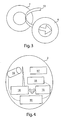
- Figure 3 schematically shows a detail of the configuration of interaction between the transmitter-responder device, or transponder, associated to a boat, and the equipped buoy of Figure 2; and
- Figure 4 schematically shows the local control station employed in the system of Figure 1.
- In the following of the description same references will be used to indicate alike elements in the Figures.
- The system developed by the inventors is an effective technical solution which is capable to reconcile both the needs of the sea parks, which have to protect the environment and obtain economic compensations from the visits of the pleasure craft users, and the needs of these, which wish to enjoy the sea environment having real services in exchange for the payment of an admission fee.
- In particular, the system according to the invention comprises the creation of appropriate buoy fields enabling the controlled docking of boats with no need of anchoring in specific zones of a sea park. Such buoy fields, together with a prohibition of anchoring, assure the protection of the sea bottom, the possibility to issue a limited number of permission of staying at a park, determined by the number of available buoys, the economic gain for the management of the park, and the satisfaction of the pleasure craft users.
- The system according to the invention is an automated system for monitoring and managing the buoys, so as to assure a total control of the buoy fields by the administrative office of a park, the collection of the admission fee and the repression of not authorised exploitations of services.
- With reference to Figure 1, the preferred embodiment of the system according to the invention comprises a field having one or more equipped
buoys 1, apt to communicate with alocal control station 2, which in turn communicates with anoperative centre 3. In particular, thelocal control station 2 may manage any number ofbuoys 1 distributed within the range of hundreds of meters, while theoperative centre 3 may manage any number oflocal control stations 2. - As shown in Figure 2, an equipped
buoy 1 employed in the preferred embodiment of the system according to the invention comprises afloat 4, preferably made of plastic reinforced by fibber glass and/or polycarbonate, inside which it is housed an electronic unit 5 connected to anantenna 6, preferably installed inside a ring placed on the top of thefloat 4. Through theantenna 6, the electronic unit 5, preferably provided with a microprocessor, continuously transmits an interrogation signal within the surrounding environment and it is apt to carry out a passive radio frequency communication with a transmitter-responder, or transponder, having no power supply. - The transponder, schematically shown in Figure 3 with
reference numeral 7, receive the energy necessary for its own operation directly from theantenna 6 and talks with the electronic unit 5 giving its own identification code. In other words, the electronic unit 5 is apt to carry out the recognition oftransponders 7 and, consequently, to detect the mooring of a boat. The system according to the invention provides for giving to each pleasure craft user, who requests it, acorresponding transponder 7 programmed with boat and/or pleasure craft user identification data; these data are further memorised in theoperative centre 3, where they may be associated to other data concerning, for instance, the type of service requested by the pleasure craft user to which thetransponder 7 corresponds. Thetransponder 7 of the preferred embodiment of the system according to the invention is contained within a watertight shock-resistant floating plastic material moulded container which incorporates and protects it; its memory uniquely contains an encrypted code corresponding to its serial number, to which the data related to the user recorded and associated to the transponder itself are associated in the memory of the operative centre. Thetransponder 7 has a ring shape corresponding to the one of theantenna 6 of the equippedbuoy 1, so that, once themooring rope 13 is passed into the two corresponding rings, thetransponder 7 is in electromagnetic visibility conditions with theantenna 6, preferably with the two corresponding rings in contact with each other. Preferably, the ring of theantenna 6 further includes detecting means, for example infrared photodiode and/or phototransistor devices, apt to detect the passage of a rope into the ring itself. - The association between the
transponder 7 and the corresponding pleasure craft user (or the boat) enables, at the moment of docking, to verify the compliance with the administrative requirements, controlling the related credit, memorised in the operative centre. In particular, thetransponders 7 are produced in large quantity and given to the users, together with an instruction sheet, after payment of a fee for the requested service, such as for instance the permission of staying at the park for a determined period, and a deposit fee, preferably equal to twice its cost, which is given back when thetransponder 7 is returned; the user may also definitively keep it, by remotely activating the account when he intends to exploit the service. - Still with reference to Figure 2, the equipped
buoy 1 still comprises aradio communication device 8, provided with a corresponding antenna 9, apt to grant. the communication betweenbuoy 1 andlocal control station 2. Preferably, the radio communications between equippedbuoy 1 andlocal control station 2 are based on the Wifi standard. The equippedbuoy 1 is further provided with an autonomous power supply internal to thefloat 4, comprising asolar panel 10 and astorage battery 11. In particular, thesolar panel 10 is advantageously placed in correspondence with a transparent portion of thefloat 4, preferably a window, which allows the external light to illuminate the sensitive area of thesolar panel 10. - All the electronic components of the equipped
buoy 1 are sealed within thefloat 4, which is watertight, so as not to suffer damages from the exposition to the brackish atmosphere. - The
float 4 is kept in position through a sinker, not shown, resting on the bottom, to which it is hooked through a chain, not shown, coupled to ananchoring ring 12 placed at the bottom of thefloat 4. - With reference to Figure 4, it may be observed that the
local control station 2 comprises aradiocommunication unit 14 apt to communicate with the equippedbuoys 1 of the field that it controls. Theunit 14, which is preferably a Wifi Access Point, is connected to adevice 15 of outward, preferably telephonic, communication, via cable or GPRS, and/or (for example in the case when GPRS signal lacks) to a radio link for connecting to theoperative centre 3. - The
local station 2 is also provided with acamera 16 for video taking the buoy field, the image of which is displayed on the monitors of theoperative centre 3, completed with information provided by the equippedbuoys 1. - The
local station 2 is preferably contained in a protective mimetic structure, for instance made of a watertight container in rock shape preferably made of fibber glass and/or polycarbonate, within which the electronic components and the power supply are housed, comprising at least onesolar panel 17 and astorage battery 18. A controlelectronic unit 19 controls the operation of thelocal station 2. - The
local station 2 is the link between the equipped buoys 1, with which it forms a wireless local area network or WLAN, and theoperative centre 3, to which it transfers the data collected by the equipped buoys 1 and the images taken by thecamera 16 aiming at the buoy field, in order to prove mooring infractions and/or to give evidences of illegal behaviours, such as forbidden anchoring or fishing. In particular, the information from thelocal control stations 2 reach theoperative centre 3 preferably through Internet link with protected connection. - The
operative centre 3 has a primary role in the system according to the invention. In fact, it is provided with means apt to program thetransponders 7 given to the pleasure craft users. Moreover, in theoperative centre 3 the state of the equipped buoys 1 of all the buoy fields spread over the park is controlled, for which it is provided a correspondinglocal control station 2. In fact, as already mentioned, thebuoys 1 are capable to detect the presence of thetransponders 7 and mooring abuse, transmitting data to the correspondinglocal control station 2. This one provides the information, with the image of the buoy field taken by thecamera 16 and transmits all to theoperative centre 3. In particular, the image of the buoy field is displayed on monitors with which theoperative centre 3 is provided, together with windows containing the information coming from the several equippedbuoys 1 of the corresponding field, so as to give evidences of possible mooring abuses, even when the buoy device should be eluded, and to take punishing actions. - Preferably, the system according to the invention enables the extension of services which may be exploited by a user through SMS (Short Message Service) messages coming from a cellular telephone associated to the
corresponding transponder 7; the system may further enable the warning of expiration of the pre-paid time, still through a SMS message sent to the same cellular telephone appropriately in advance. Such service will result particularly welcome to the pleasure craft users who would wish to stay more than they estimated, without leaving the mooring in order to get to theoperative centre 3 for renewing the permission of staying. - Advantageously, in the
operative centre 3 there are operators capable to interpret data and images, to have relationships with the users for distributing thetransponders 7, for collecting the corresponding fees, and for solving management problems. In particular, the organisation may be represented by a classic configuration with Front Office and Back Office. - At the Front Office users are received,
transponders 7 are programmed and handed, telephone calls and messages for requested service extension are received, possible complaints are processed. - At the Back Office the information system is managed, electrical and mechanical maintenance of the components of the system is made, possible illegal behaviours are controlled, information are transmitted to authorities.
- The
operative centre 3 may take advantage of entering into agreements with cellular telephony companies, for making possible the recharge of the user accounts through SMS or e-mail. - The preferred embodiments have been above described and some modifications of this invention have been suggested, but it should be understood that those skilled in the art can make other variations and changes, without so departing from the related scope of protection, as defined by the following claims.
Claims (18)
- System for controlling and managing docking in a sea area, comprising at least one control station (2) and further comprising one or more fields, characterised in that said fields have one or more buoys and in that said buoys are equipped buoys (1) apt to communicate with said at least one control station (2), each one of said equipped buoys (1) comprising first radiocommunication means (8; 9) apt to communicate with second radiocommunication means (14) with which said at least one control station (2) is provided, each one of said equipped buoys (1) further comprising electronic means (5; 6) apt to transmit an interrogation signal for carrying out a passive radio frequency communication with at least one transmitter-responder or transponder (7), in such a way that said at least one transponder (7), when interrogated, talks with the electronic means (5; 6) providing at least one identification code, the electronic means (5; 6) transmitting, through the first radiocommunication means (8; 9), said at least one identification code to said at least one control station (2).
- System according to claim 1, characterised in that it further comprises an operative centre (3), said at least one control station (2) of each buoy field comprising further communication means (15) apt to communicate with the operative centre (3), said at least one control station (2) being apt to send to this information related to the corresponding buoy field.
- System according to claim 1 or 2, characterised in that the electronic means (5; 6) comprises an antenna (6) housed in a structure of the equipped buoy (1), said at least one transponder (7) having a housing having a shape apt to spatially arrange itself with respect to said structure of the antenna (6) in such a way to achieve electromagnetic visibility conditions with the antenna (6) itself.
- System according to claim 3, characterised in that the structure housing the antenna (6) and the housing of the transponder (7) have the shape of two corresponding rings.
- System according to claim 4, characterised in that the ring structure housing the antenna (6) is apt to receive a passing rope (13) and is provided with means detecting the presence of a rope (13), following the detection of the presence of a rope (13) the electronic means (5; 6) transmitting said interrogation signal.
- System according to any one of the preceding claims 3 to 5, characterised in that each one of said equipped buoys (1) comprises a float (4), to which the structure housing the antenna (6) is coupled, the interior of the float (4) and of the structure housing the antenna (6) being watertight, an autonomous electric power supply (10; 11) being housed within the float (4), which supply comprises at least one solar panel (10), housed in correspondence with at least one transparent portion of the float (4), connected to a power supply storage battery (11).
- System according to claim 6, characterised in that the float (4) is in plastic reinforced by fibber glass and/or polycarbonate.
- System according to any one of the preceding claims, characterised in that the first radiocommunication means (8; 9) is apt to communicate with the second radiocommunication means (14) according to the Wifi communication standard.
- System according to any one of the preceding claims, characterised in that said at least one control station (2) is housed in a mimetic structure, comprising at least one solar panel (17) connected to a power supply storage battery (18).
- System according to claim 9, characterised in that the mimetic structure of said at least one control station (2) is a watertight container in rock shape made of fibber glass and/or polycarbonate.
- System according to any one of the preceding claims, characterised in that said at least one control station (2) comprises at least one camera (16) for video taking the corresponding buoy field.
- System according to claim 11, when dependent on claim 2, characterised in that said at least one control station (2) is apt to send to the operative centre (3) one or more images taken by said at least one camera (16).
- System according to any one of the preceding claims, characterised in that said at least one transponder (7) is contained within a watertight shock-resistant floating plastic material moulded container.
- System according to any one of the preceding claims, characterised in that said at least one transponder (7) memorises said at least one identification code in encrypted form.
- System according to claim 2 or any one of claims 3 to 14, when dependent on claim 2, characterised in that said further communication means (15) of said at least one control station (2) comprises at least one device (15) of telephonic communication, via cable or GPRS, and/or at least one communication device (15) through radio link for connecting to the operative centre (3).
- System according to claim 15, characterised in that the communication between said at least one control station (2) and the operative centre (3) occurs through protected Internet connection.
- System according to claim 2 or any one of claims 3 to 16, when dependent on claim 2, characterised in that the operative centre (3) comprises further communication means through cellular telephony via SMS (Short Message Service) messages.
- Equipped buoy (1) characterised in that it comprises first radiocommunication means (8; 9) apt to communicate with second radiocommunication means (14) with which at least one control station (2) is provided, in that it also comprises electronic means (5; 6) apt to transmit an interrogation signal for carrying out a passive radio frequency communication with at least one transponder (7), in such a way that said at least one transponder. (7), when interrogated, talks with the electronic means (5; 6) providing at least one identification code, the electronic means (5; 6) transmitting, through the first radiocommunication means (8; 9), said at least one identification code to said at least one control station (2), the equipped buoy (1) being further characterised in that it is usable in a system for controlling and managing docking in a sea area according to any one of the preceding claims 1-17.
Priority Applications (2)
| Application Number | Priority Date | Filing Date | Title |
|---|---|---|---|
| SI200331132T SI1550086T1 (en) | 2002-10-07 | 2003-09-29 | System for controlling and managing docking in a sea area |
| CY20081100278T CY1107904T1 (en) | 2002-10-07 | 2008-03-12 | SYSTEM FOR CONTROL AND MANAGEMENT OF MARINE AREA |
Applications Claiming Priority (3)
| Application Number | Priority Date | Filing Date | Title |
|---|---|---|---|
| IT000507A ITRM20020507A1 (en) | 2002-10-07 | 2002-10-07 | MOUNTING CONTROL AND MANAGEMENT SYSTEM. |
| ITRM20020507 | 2002-10-07 | ||
| PCT/IT2003/000582 WO2004032064A1 (en) | 2002-10-07 | 2003-09-29 | System for controlling and managing docking in a sea area |
Publications (2)
| Publication Number | Publication Date |
|---|---|
| EP1550086A1 EP1550086A1 (en) | 2005-07-06 |
| EP1550086B1 true EP1550086B1 (en) | 2007-12-12 |
Family
ID=11456515
Family Applications (1)
| Application Number | Title | Priority Date | Filing Date |
|---|---|---|---|
| EP03758685A Expired - Lifetime EP1550086B1 (en) | 2002-10-07 | 2003-09-29 | System for controlling and managing docking in a sea area |
Country Status (11)
| Country | Link |
|---|---|
| EP (1) | EP1550086B1 (en) |
| AT (1) | ATE381080T1 (en) |
| AU (1) | AU2003274723A1 (en) |
| CY (1) | CY1107904T1 (en) |
| DE (1) | DE60318087T2 (en) |
| DK (1) | DK1550086T3 (en) |
| ES (1) | ES2297212T3 (en) |
| HR (1) | HRP20050302A2 (en) |
| IT (1) | ITRM20020507A1 (en) |
| PT (1) | PT1550086E (en) |
| WO (1) | WO2004032064A1 (en) |
Cited By (1)
| Publication number | Priority date | Publication date | Assignee | Title |
|---|---|---|---|---|
| EP4063254A1 (en) * | 2021-03-05 | 2022-09-28 | HERMES Bootbau OG | Smart buoy |
Families Citing this family (8)
| Publication number | Priority date | Publication date | Assignee | Title |
|---|---|---|---|---|
| DE102006038808B4 (en) * | 2006-08-18 | 2008-09-04 | Sabik Informationssysteme Gmbh | Method and device for remote monitoring of beacons |
| SI22933A (en) | 2010-02-02 | 2010-06-30 | SKLAD@NEPREMIÄŚNIN@d@o@o | Assembly for automatic supervision and control of the use of mooringsfor vessels including automatic floating buoys and method associated with it |
| US9834283B2 (en) | 2014-07-31 | 2017-12-05 | Jkp Marine Pty Ltd | Mooring system and mooring buoy |
| WO2018102851A1 (en) * | 2016-12-05 | 2018-06-14 | Jkp Marine Pty Ltd | Modular mooring buoy system, and buoyant body and modular unit thereof |
| CN111315648B (en) * | 2017-11-08 | 2022-08-30 | 邦菲利奥·普拉特 | Mooring buoy |
| FR3094337B1 (en) * | 2019-03-28 | 2022-10-21 | Etm | MOORING SYSTEM COMPRISING A PLURALITY OF BUOYS EQUIPPED WITH COMMUNICATION UNITS |
| DE102020207079A1 (en) | 2020-06-05 | 2021-12-09 | Zf Friedrichshafen Ag | Assistance system for watercraft |
| IT202100030542A1 (en) | 2021-12-03 | 2023-06-03 | Hytem S R L | Ecological underwater buoy with retractable mooring line especially for marine protected areas. |
Family Cites Families (4)
| Publication number | Priority date | Publication date | Assignee | Title |
|---|---|---|---|---|
| US4903243A (en) * | 1988-08-04 | 1990-02-20 | Whistler Corporation | Marine transponder system |
| US5751973A (en) * | 1990-05-17 | 1998-05-12 | At/Comm Incorporated | Electronic parking and dispatching management method and apparatus |
| DE19726015A1 (en) * | 1997-06-19 | 1999-01-07 | Frank Pistorius | Alarm system for securing boats moored on jetty |
| EP0945552B1 (en) * | 1997-10-22 | 2006-04-26 | The Yokohama Rubber Co., Ltd. | Fender and a management system therefor |
-
2002
- 2002-10-07 IT IT000507A patent/ITRM20020507A1/en unknown
-
2003
- 2003-09-29 ES ES03758685T patent/ES2297212T3/en not_active Expired - Lifetime
- 2003-09-29 WO PCT/IT2003/000582 patent/WO2004032064A1/en active IP Right Grant
- 2003-09-29 PT PT03758685T patent/PT1550086E/en unknown
- 2003-09-29 DK DK03758685T patent/DK1550086T3/en active
- 2003-09-29 AU AU2003274723A patent/AU2003274723A1/en not_active Abandoned
- 2003-09-29 EP EP03758685A patent/EP1550086B1/en not_active Expired - Lifetime
- 2003-09-29 AT AT03758685T patent/ATE381080T1/en not_active IP Right Cessation
- 2003-09-29 DE DE60318087T patent/DE60318087T2/en not_active Expired - Lifetime
-
2005
- 2005-03-31 HR HR20050302A patent/HRP20050302A2/en not_active Application Discontinuation
-
2008
- 2008-03-12 CY CY20081100278T patent/CY1107904T1/en unknown
Non-Patent Citations (1)
| Title |
|---|
| None * |
Cited By (1)
| Publication number | Priority date | Publication date | Assignee | Title |
|---|---|---|---|---|
| EP4063254A1 (en) * | 2021-03-05 | 2022-09-28 | HERMES Bootbau OG | Smart buoy |
Also Published As
| Publication number | Publication date |
|---|---|
| WO2004032064A1 (en) | 2004-04-15 |
| HRP20050302A2 (en) | 2005-10-31 |
| DE60318087D1 (en) | 2008-01-24 |
| ITRM20020507A0 (en) | 2002-10-07 |
| CY1107904T1 (en) | 2013-09-04 |
| DK1550086T3 (en) | 2008-05-05 |
| ITRM20020507A1 (en) | 2004-04-08 |
| AU2003274723A1 (en) | 2004-04-23 |
| ATE381080T1 (en) | 2007-12-15 |
| DE60318087T2 (en) | 2008-11-27 |
| PT1550086E (en) | 2008-03-19 |
| EP1550086A1 (en) | 2005-07-06 |
| ES2297212T3 (en) | 2008-05-01 |
Similar Documents
| Publication | Publication Date | Title |
|---|---|---|
| EP2531981B1 (en) | System for automatic managing and controlling the use of moorings for vessels, comprising automated floating buoys and the related method | |
| AU682694B2 (en) | Antitheft system integrated with functions of security, information and navigation, based on electronic cartography,vocal synthesis and radio telecommunication | |
| CN100385897C (en) | Equipment forbidden device | |
| US10920458B2 (en) | Protective case | |
| EP1550086B1 (en) | System for controlling and managing docking in a sea area | |
| FI86113B (en) | CONTROL OF OVER FOUNDATION FOR QUANTITY OF CONTROLS AND ENCLOSURES. | |
| CN106205046B (en) | A kind of intelligent residential district personnel management system | |
| US20050222933A1 (en) | System and method for monitoring and control of wireless modules linked to assets | |
| KR101583631B1 (en) | Integrated management system for marina port | |
| CN107016434A (en) | A kind of electronic tag based on LPWAN and RFID technique | |
| CA2905586C (en) | Remote trespassing detection and notification system and method | |
| CN110014937A (en) | Equipment for charging to accumulator | |
| US4978942A (en) | Disguised beam-break security system | |
| CA2923686A1 (en) | Onboard unit for a vehicular identification system | |
| CN108909898A (en) | Shared bicycle and its storage box | |
| GB2236354A (en) | Combined key/radio pager | |
| RU99643U1 (en) | SYSTEM OF NAVIGATION, SECURITY AND MONITORING OF MOBILE OBJECTS | |
| CN108597142A (en) | A kind of intelligent parking charge stake | |
| CN209028792U (en) | A kind of multi-functional, alarming recourse device | |
| CA2029145A1 (en) | Electronic systems for the protection of articles | |
| CN101639971B (en) | Method and equipment for protecting personal safety or property safety | |
| RU2174923C1 (en) | System for providing monitoring, information services and protection of mobile objects from unauthorized actions | |
| Srinivasan et al. | An embedded system and rftd solutton for transport related tssues | |
| FR2587664A1 (en) | Access surveillance and anti-theft alarm device for sea or land vehicles. Claims of the device and its use | |
| EP2526536B1 (en) | Control system for vehicle displacements |
Legal Events
| Date | Code | Title | Description |
|---|---|---|---|
| PUAI | Public reference made under article 153(3) epc to a published international application that has entered the european phase |
Free format text: ORIGINAL CODE: 0009012 |
|
| 17P | Request for examination filed |
Effective date: 20040428 |
|
| AK | Designated contracting states |
Kind code of ref document: A1 Designated state(s): AT BE BG CH CY CZ DE DK EE ES FI FR GB GR HU IE IT LI LU MC NL PT RO SE SI SK TR |
|
| AX | Request for extension of the european patent |
Extension state: AL LT LV MK |
|
| DAX | Request for extension of the european patent (deleted) | ||
| GRAP | Despatch of communication of intention to grant a patent |
Free format text: ORIGINAL CODE: EPIDOSNIGR1 |
|
| GRAS | Grant fee paid |
Free format text: ORIGINAL CODE: EPIDOSNIGR3 |
|
| GRAF | Information related to payment of grant fee modified |
Free format text: ORIGINAL CODE: EPIDOSCIGR3 |
|
| GRAA | (expected) grant |
Free format text: ORIGINAL CODE: 0009210 |
|
| AK | Designated contracting states |
Kind code of ref document: B1 Designated state(s): AT BE BG CH CY CZ DE DK EE ES FI FR GB GR HU IE IT LI LU MC NL PT RO SE SI SK TR |
|
| REG | Reference to a national code |
Ref country code: GB Ref legal event code: FG4D |
|
| BECA | Be: change of holder's address |
Owner name: ITALGEST MARE S.P.A.VIA MONTE ROSA Z.I., I-73040 M Effective date: 20071212 |
|
| BECH | Be: change of holder |
Owner name: ITALGEST MARE S.P.A. Effective date: 20071212 |
|
| REG | Reference to a national code |
Ref country code: CH Ref legal event code: EP |
|
| REG | Reference to a national code |
Ref country code: IE Ref legal event code: FG4D |
|
| REF | Corresponds to: |
Ref document number: 60318087 Country of ref document: DE Date of ref document: 20080124 Kind code of ref document: P |
|
| REG | Reference to a national code |
Ref country code: RO Ref legal event code: EPE |
|
| RAP2 | Party data changed (patent owner data changed or rights of a patent transferred) |
Owner name: ITALGEST MARE S.P.A. |
|
| REG | Reference to a national code |
Ref country code: PT Ref legal event code: SC4A Free format text: AVAILABILITY OF NATIONAL TRANSLATION Effective date: 20080307 |
|
| REG | Reference to a national code |
Ref country code: SE Ref legal event code: TRGR |
|
| PG25 | Lapsed in a contracting state [announced via postgrant information from national office to epo] |
Ref country code: LI Free format text: LAPSE BECAUSE OF FAILURE TO SUBMIT A TRANSLATION OF THE DESCRIPTION OR TO PAY THE FEE WITHIN THE PRESCRIBED TIME-LIMIT Effective date: 20071212 Ref country code: CH Free format text: LAPSE BECAUSE OF FAILURE TO SUBMIT A TRANSLATION OF THE DESCRIPTION OR TO PAY THE FEE WITHIN THE PRESCRIBED TIME-LIMIT Effective date: 20071212 |
|
| NLT2 | Nl: modifications (of names), taken from the european patent patent bulletin |
Owner name: ITALGEST MARE S.P.A. Effective date: 20080305 |
|
| REG | Reference to a national code |
Ref country code: ES Ref legal event code: FG2A Ref document number: 2297212 Country of ref document: ES Kind code of ref document: T3 |
|
| REG | Reference to a national code |
Ref country code: DK Ref legal event code: T3 |
|
| NLS | Nl: assignments of ep-patents |
Owner name: ITALGEST MARE S.P.A. Effective date: 20080321 |
|
| REG | Reference to a national code |
Ref country code: CH Ref legal event code: PL |
|
| PG25 | Lapsed in a contracting state [announced via postgrant information from national office to epo] |
Ref country code: AT Free format text: LAPSE BECAUSE OF FAILURE TO SUBMIT A TRANSLATION OF THE DESCRIPTION OR TO PAY THE FEE WITHIN THE PRESCRIBED TIME-LIMIT Effective date: 20071212 |
|
| PG25 | Lapsed in a contracting state [announced via postgrant information from national office to epo] |
Ref country code: CZ Free format text: LAPSE BECAUSE OF FAILURE TO SUBMIT A TRANSLATION OF THE DESCRIPTION OR TO PAY THE FEE WITHIN THE PRESCRIBED TIME-LIMIT Effective date: 20071212 |
|
| ET | Fr: translation filed | ||
| PG25 | Lapsed in a contracting state [announced via postgrant information from national office to epo] |
Ref country code: SK Free format text: LAPSE BECAUSE OF FAILURE TO SUBMIT A TRANSLATION OF THE DESCRIPTION OR TO PAY THE FEE WITHIN THE PRESCRIBED TIME-LIMIT Effective date: 20071212 |
|
| PLBE | No opposition filed within time limit |
Free format text: ORIGINAL CODE: 0009261 |
|
| STAA | Information on the status of an ep patent application or granted ep patent |
Free format text: STATUS: NO OPPOSITION FILED WITHIN TIME LIMIT |
|
| 26N | No opposition filed |
Effective date: 20080915 |
|
| PG25 | Lapsed in a contracting state [announced via postgrant information from national office to epo] |
Ref country code: GR Free format text: LAPSE BECAUSE OF FAILURE TO SUBMIT A TRANSLATION OF THE DESCRIPTION OR TO PAY THE FEE WITHIN THE PRESCRIBED TIME-LIMIT Effective date: 20080313 |
|
| PG25 | Lapsed in a contracting state [announced via postgrant information from national office to epo] |
Ref country code: IT Free format text: LAPSE BECAUSE OF NON-PAYMENT OF DUE FEES Effective date: 20080929 |
|
| PGFP | Annual fee paid to national office [announced via postgrant information from national office to epo] |
Ref country code: DK Payment date: 20090914 Year of fee payment: 7 Ref country code: EE Payment date: 20090811 Year of fee payment: 7 Ref country code: IE Payment date: 20090914 Year of fee payment: 7 Ref country code: MC Payment date: 20090827 Year of fee payment: 7 |
|
| PGFP | Annual fee paid to national office [announced via postgrant information from national office to epo] |
Ref country code: FI Payment date: 20090914 Year of fee payment: 7 Ref country code: GB Payment date: 20090923 Year of fee payment: 7 Ref country code: NL Payment date: 20090903 Year of fee payment: 7 Ref country code: PT Payment date: 20090929 Year of fee payment: 7 Ref country code: RO Payment date: 20090812 Year of fee payment: 7 Ref country code: SE Payment date: 20090910 Year of fee payment: 7 Ref country code: SI Payment date: 20090731 Year of fee payment: 7 Ref country code: TR Payment date: 20090903 Year of fee payment: 7 |
|
| PGFP | Annual fee paid to national office [announced via postgrant information from national office to epo] |
Ref country code: CY Payment date: 20090827 Year of fee payment: 7 |
|
| PGFP | Annual fee paid to national office [announced via postgrant information from national office to epo] |
Ref country code: BG Payment date: 20090915 Year of fee payment: 7 Ref country code: DE Payment date: 20091125 Year of fee payment: 7 Ref country code: ES Payment date: 20091006 Year of fee payment: 7 |
|
| PGFP | Annual fee paid to national office [announced via postgrant information from national office to epo] |
Ref country code: BE Payment date: 20090917 Year of fee payment: 7 |
|
| PGFP | Annual fee paid to national office [announced via postgrant information from national office to epo] |
Ref country code: FR Payment date: 20091012 Year of fee payment: 7 |
|
| PG25 | Lapsed in a contracting state [announced via postgrant information from national office to epo] |
Ref country code: LU Free format text: LAPSE BECAUSE OF NON-PAYMENT OF DUE FEES Effective date: 20080929 Ref country code: HU Free format text: LAPSE BECAUSE OF FAILURE TO SUBMIT A TRANSLATION OF THE DESCRIPTION OR TO PAY THE FEE WITHIN THE PRESCRIBED TIME-LIMIT Effective date: 20080613 |
|
| BERE | Be: lapsed |
Owner name: ITALGEST MARE S.P.A. Effective date: 20100930 |
|
| REG | Reference to a national code |
Ref country code: PT Ref legal event code: MM4A Free format text: LAPSE DUE TO NON-PAYMENT OF FEES Effective date: 20110329 |
|
| REG | Reference to a national code |
Ref country code: NL Ref legal event code: V1 Effective date: 20110401 |
|
| PG25 | Lapsed in a contracting state [announced via postgrant information from national office to epo] |
Ref country code: MC Free format text: LAPSE BECAUSE OF NON-PAYMENT OF DUE FEES Effective date: 20100930 |
|
| REG | Reference to a national code |
Ref country code: SE Ref legal event code: EUG |
|
| GBPC | Gb: european patent ceased through non-payment of renewal fee |
Effective date: 20100929 |
|
| REG | Reference to a national code |
Ref country code: DK Ref legal event code: EBP |
|
| PG25 | Lapsed in a contracting state [announced via postgrant information from national office to epo] |
Ref country code: CY Free format text: LAPSE BECAUSE OF NON-PAYMENT OF DUE FEES Effective date: 20100929 Ref country code: PT Free format text: LAPSE BECAUSE OF NON-PAYMENT OF DUE FEES Effective date: 20110329 Ref country code: FI Free format text: LAPSE BECAUSE OF NON-PAYMENT OF DUE FEES Effective date: 20100929 |
|
| REG | Reference to a national code |
Ref country code: EE Ref legal event code: MM4A Ref document number: E001873 Country of ref document: EE Effective date: 20100930 |
|
| REG | Reference to a national code |
Ref country code: FR Ref legal event code: ST Effective date: 20110531 |
|
| REG | Reference to a national code |
Ref country code: SI Ref legal event code: KO00 Effective date: 20110506 |
|
| REG | Reference to a national code |
Ref country code: DE Ref legal event code: R119 Ref document number: 60318087 Country of ref document: DE Effective date: 20110401 |
|
| PG25 | Lapsed in a contracting state [announced via postgrant information from national office to epo] |
Ref country code: FR Free format text: LAPSE BECAUSE OF NON-PAYMENT OF DUE FEES Effective date: 20100930 Ref country code: IE Free format text: LAPSE BECAUSE OF NON-PAYMENT OF DUE FEES Effective date: 20100929 Ref country code: BE Free format text: LAPSE BECAUSE OF NON-PAYMENT OF DUE FEES Effective date: 20100930 Ref country code: DE Free format text: LAPSE BECAUSE OF NON-PAYMENT OF DUE FEES Effective date: 20110401 Ref country code: EE Free format text: LAPSE BECAUSE OF NON-PAYMENT OF DUE FEES Effective date: 20100930 |
|
| PGFP | Annual fee paid to national office [announced via postgrant information from national office to epo] |
Ref country code: IT Payment date: 20090731 Year of fee payment: 7 |
|
| PGRI | Patent reinstated in contracting state [announced from national office to epo] |
Ref country code: IT Effective date: 20110616 |
|
| PG25 | Lapsed in a contracting state [announced via postgrant information from national office to epo] |
Ref country code: BG Free format text: LAPSE BECAUSE OF NON-PAYMENT OF DUE FEES Effective date: 20110430 Ref country code: SI Free format text: LAPSE BECAUSE OF NON-PAYMENT OF DUE FEES Effective date: 20100930 Ref country code: GB Free format text: LAPSE BECAUSE OF NON-PAYMENT OF DUE FEES Effective date: 20100929 Ref country code: NL Free format text: LAPSE BECAUSE OF NON-PAYMENT OF DUE FEES Effective date: 20110401 |
|
| REG | Reference to a national code |
Ref country code: ES Ref legal event code: FD2A Effective date: 20111019 |
|
| PG25 | Lapsed in a contracting state [announced via postgrant information from national office to epo] |
Ref country code: DK Free format text: LAPSE BECAUSE OF NON-PAYMENT OF DUE FEES Effective date: 20100930 |
|
| PG25 | Lapsed in a contracting state [announced via postgrant information from national office to epo] |
Ref country code: RO Free format text: LAPSE BECAUSE OF NON-PAYMENT OF DUE FEES Effective date: 20100929 Ref country code: ES Free format text: LAPSE BECAUSE OF NON-PAYMENT OF DUE FEES Effective date: 20100930 |
|
| PG25 | Lapsed in a contracting state [announced via postgrant information from national office to epo] |
Ref country code: SE Free format text: LAPSE BECAUSE OF NON-PAYMENT OF DUE FEES Effective date: 20100930 |
|
| PG25 | Lapsed in a contracting state [announced via postgrant information from national office to epo] |
Ref country code: TR Free format text: LAPSE BECAUSE OF NON-PAYMENT OF DUE FEES Effective date: 20100929 |
|
| PG25 | Lapsed in a contracting state [announced via postgrant information from national office to epo] |
Ref country code: BG Free format text: LAPSE BECAUSE OF NON-PAYMENT OF DUE FEES Effective date: 20110630 |
|
| PGRI | Patent reinstated in contracting state [announced from national office to epo] |
Ref country code: IT Effective date: 20110616 |