EP4063239A1 - Battery pack support device for vehicle - Google Patents
Battery pack support device for vehicle Download PDFInfo
- Publication number
- EP4063239A1 EP4063239A1 EP20894134.4A EP20894134A EP4063239A1 EP 4063239 A1 EP4063239 A1 EP 4063239A1 EP 20894134 A EP20894134 A EP 20894134A EP 4063239 A1 EP4063239 A1 EP 4063239A1
- Authority
- EP
- European Patent Office
- Prior art keywords
- bracket
- battery pack
- vehicle
- support device
- battery
- Prior art date
- Legal status (The legal status is an assumption and is not a legal conclusion. Google has not performed a legal analysis and makes no representation as to the accuracy of the status listed.)
- Granted
Links
Images


Classifications
-
- B—PERFORMING OPERATIONS; TRANSPORTING
- B60—VEHICLES IN GENERAL
- B60K—ARRANGEMENT OR MOUNTING OF PROPULSION UNITS OR OF TRANSMISSIONS IN VEHICLES; ARRANGEMENT OR MOUNTING OF PLURAL DIVERSE PRIME-MOVERS IN VEHICLES; AUXILIARY DRIVES FOR VEHICLES; INSTRUMENTATION OR DASHBOARDS FOR VEHICLES; ARRANGEMENTS IN CONNECTION WITH COOLING, AIR INTAKE, GAS EXHAUST OR FUEL SUPPLY OF PROPULSION UNITS IN VEHICLES
- B60K1/00—Arrangement or mounting of electrical propulsion units
- B60K1/04—Arrangement or mounting of electrical propulsion units of the electric storage means for propulsion
-
- B—PERFORMING OPERATIONS; TRANSPORTING
- B62—LAND VEHICLES FOR TRAVELLING OTHERWISE THAN ON RAILS
- B62D—MOTOR VEHICLES; TRAILERS
- B62D21/00—Understructures, i.e. chassis frame on which a vehicle body may be mounted
- B62D21/02—Understructures, i.e. chassis frame on which a vehicle body may be mounted comprising longitudinally or transversely arranged frame members
-
- B—PERFORMING OPERATIONS; TRANSPORTING
- B62—LAND VEHICLES FOR TRAVELLING OTHERWISE THAN ON RAILS
- B62D—MOTOR VEHICLES; TRAILERS
- B62D21/00—Understructures, i.e. chassis frame on which a vehicle body may be mounted
- B62D21/09—Means for mounting load bearing surfaces
-
- B—PERFORMING OPERATIONS; TRANSPORTING
- B62—LAND VEHICLES FOR TRAVELLING OTHERWISE THAN ON RAILS
- B62D—MOTOR VEHICLES; TRAILERS
- B62D21/00—Understructures, i.e. chassis frame on which a vehicle body may be mounted
- B62D21/15—Understructures, i.e. chassis frame on which a vehicle body may be mounted having impact absorbing means, e.g. a frame designed to permanently or temporarily change shape or dimension upon impact with another body
- B62D21/157—Understructures, i.e. chassis frame on which a vehicle body may be mounted having impact absorbing means, e.g. a frame designed to permanently or temporarily change shape or dimension upon impact with another body for side impacts
-
- H—ELECTRICITY
- H01—ELECTRIC ELEMENTS
- H01M—PROCESSES OR MEANS, e.g. BATTERIES, FOR THE DIRECT CONVERSION OF CHEMICAL ENERGY INTO ELECTRICAL ENERGY
- H01M50/00—Constructional details or processes of manufacture of the non-active parts of electrochemical cells other than fuel cells, e.g. hybrid cells
- H01M50/20—Mountings; Secondary casings or frames; Racks, modules or packs; Suspension devices; Shock absorbers; Transport or carrying devices; Holders
- H01M50/244—Secondary casings; Racks; Suspension devices; Carrying devices; Holders characterised by their mounting method
-
- H—ELECTRICITY
- H01—ELECTRIC ELEMENTS
- H01M—PROCESSES OR MEANS, e.g. BATTERIES, FOR THE DIRECT CONVERSION OF CHEMICAL ENERGY INTO ELECTRICAL ENERGY
- H01M50/00—Constructional details or processes of manufacture of the non-active parts of electrochemical cells other than fuel cells, e.g. hybrid cells
- H01M50/20—Mountings; Secondary casings or frames; Racks, modules or packs; Suspension devices; Shock absorbers; Transport or carrying devices; Holders
- H01M50/249—Mountings; Secondary casings or frames; Racks, modules or packs; Suspension devices; Shock absorbers; Transport or carrying devices; Holders specially adapted for aircraft or vehicles, e.g. cars or trains
-
- B—PERFORMING OPERATIONS; TRANSPORTING
- B60—VEHICLES IN GENERAL
- B60K—ARRANGEMENT OR MOUNTING OF PROPULSION UNITS OR OF TRANSMISSIONS IN VEHICLES; ARRANGEMENT OR MOUNTING OF PLURAL DIVERSE PRIME-MOVERS IN VEHICLES; AUXILIARY DRIVES FOR VEHICLES; INSTRUMENTATION OR DASHBOARDS FOR VEHICLES; ARRANGEMENTS IN CONNECTION WITH COOLING, AIR INTAKE, GAS EXHAUST OR FUEL SUPPLY OF PROPULSION UNITS IN VEHICLES
- B60K1/00—Arrangement or mounting of electrical propulsion units
- B60K1/04—Arrangement or mounting of electrical propulsion units of the electric storage means for propulsion
- B60K2001/0405—Arrangement or mounting of electrical propulsion units of the electric storage means for propulsion characterised by their position
- B60K2001/0438—Arrangement under the floor
-
- B—PERFORMING OPERATIONS; TRANSPORTING
- B60—VEHICLES IN GENERAL
- B60Y—INDEXING SCHEME RELATING TO ASPECTS CROSS-CUTTING VEHICLE TECHNOLOGY
- B60Y2200/00—Type of vehicle
- B60Y2200/10—Road Vehicles
- B60Y2200/14—Trucks; Load vehicles, Busses
-
- B—PERFORMING OPERATIONS; TRANSPORTING
- B60—VEHICLES IN GENERAL
- B60Y—INDEXING SCHEME RELATING TO ASPECTS CROSS-CUTTING VEHICLE TECHNOLOGY
- B60Y2306/00—Other features of vehicle sub-units
- B60Y2306/01—Reducing damages in case of crash, e.g. by improving battery protection
-
- H—ELECTRICITY
- H01—ELECTRIC ELEMENTS
- H01M—PROCESSES OR MEANS, e.g. BATTERIES, FOR THE DIRECT CONVERSION OF CHEMICAL ENERGY INTO ELECTRICAL ENERGY
- H01M2220/00—Batteries for particular applications
- H01M2220/20—Batteries in motive systems, e.g. vehicle, ship, plane
-
- Y—GENERAL TAGGING OF NEW TECHNOLOGICAL DEVELOPMENTS; GENERAL TAGGING OF CROSS-SECTIONAL TECHNOLOGIES SPANNING OVER SEVERAL SECTIONS OF THE IPC; TECHNICAL SUBJECTS COVERED BY FORMER USPC CROSS-REFERENCE ART COLLECTIONS [XRACs] AND DIGESTS
- Y02—TECHNOLOGIES OR APPLICATIONS FOR MITIGATION OR ADAPTATION AGAINST CLIMATE CHANGE
- Y02E—REDUCTION OF GREENHOUSE GAS [GHG] EMISSIONS, RELATED TO ENERGY GENERATION, TRANSMISSION OR DISTRIBUTION
- Y02E60/00—Enabling technologies; Technologies with a potential or indirect contribution to GHG emissions mitigation
- Y02E60/10—Energy storage using batteries
Definitions
- the present invention relates to a vehicle battery pack support device.
- Patent Document 1 In recent years, from the viewpoint of an environmental impact, electric vehicles are under development also in the field of commercial vehicles such as trucks (Patent Document 1). It is desirable that a battery pack mounted in such an electric truck is arranged between frames in terms of securing side collision safety of the battery pack.
- PATENT DOCUMENT 1 Japanese Unexamined Patent Publication No. 2016-113063
- the present invention was made to provide a vehicle battery pack support device capable of securing torsional rigidity and side collision safety of a battery pack when a battery pack having a dimension that does not fit between frames of an electric truck is mounted.
- the present invention was made to overcome at least some of the problems described above, and can be implemented as the following embodiments or application examples.
- a vehicle battery pack support device is a support device for a battery pack that is mounted below a pair of side rails extending in a longitudinal direction of a vehicle and has a pair of side faces each facing in the longitudinal direction of the vehicle, the side faces each having a long side that is orthogonal to the longitudinal direction of the vehicle and extends beyond the side rails in a vehicle width direction
- the vehicle battery pack support device comprising: a battery bracket for housing the battery pack; and a frame bracket for coupling the side rails and the battery bracket, the battery bracket including a first bracket covering the side faces of the battery pack, at least a portion of a top face that is continuous with the side faces, and at least a portion of a bottom face that is continuous with the side faces, the first bracket having a dimension in the vehicle width direction which is equal to or larger than the long side of the battery pack, and a second bracket covering an end portion of the first bracket in the vehicle width direction and coupled to the frame bracket.
- the vehicle battery pack support device has a structure in which the first brackets are longer than the long sides of the front side face and the rear side face of the battery pack, and cover the front side face and the rear side face to prevent an impact from being directly transferred to the battery pack even when the impact is applied from a lateral side in the vehicle width direction.
- the second brackets cover end portions of the first brackets in the vehicle width direction, so that it is possible to improve torsional rigidity of the battery bracket and substantially prevent fragments or the like from directly reaching the battery pack even when an object collides from a lateral side in the vehicle width direction.
- the battery bracket including the first brackets and the second brackets can be easily formed so as to fit the shape of the battery pack. Further, the battery bracket is coupled to the side rails via the frame bracket to support the battery pack, so that the battery pack that has a size larger than the distance between the frames of the electric truck can be easily mounted, and that torsional rigidity and side collision safety of the battery pack can be secured.
- the first bracket may include: a first web that covers the side face of the battery pack facing a front side of the vehicle; a first top flange that is continuous with the first web and covers the top face; and a first bottom flange that is continuous with the first web and covers the bottom face. It is thus possible to cushion an impact applied from the front side of the vehicle, and improve front collision safety of the battery pack.
- the first bracket may have a cylindrical shape integrally covering the side faces, the top face, and the bottom face. This configuration can further improve torsional rigidity of the battery bracket.
- the second bracket may include: a second top flange coupled to the first top flange of the first bracket; a second bottom flange coupled to the first bottom flange of the first bracket; and a second web coupling the second top flange and the second bottom flange. Therefore, the second bracket has a structure of sandwiching and holding the first bracket, which makes it possible to improve torsional rigidity of the battery bracket.
- At least one of the second top flange or the second bottom flange of the second bracket may be formed to have a larger dimension in the vehicle width direction at an end portion in the longitudinal direction of the vehicle than that of a central portion. It is thus possible to reduce weight of the battery bracket and secure torsional rigidity of the battery bracket.
- a space may be formed between the second web of the second bracket and a side face of the battery pack in the vehicle width direction. It is thus possible to substantially prevent a situation in which even when the second brackets are deformed due to an impact applied from the side of the vehicle, the second brackets directly come into contact with the battery pack and transfer the impact.
- FIG. 1 is a schematic top view illustrating an overall configuration of a vehicle including a vehicle battery pack support device according to the present embodiment.
- the shapes of components described below are, basically, horizontally symmetrical with respect to the center of the vehicle 1 in a vehicle width direction (Y direction in the drawings). Therefore, basically, only one of left and right components is described in the following description, but the other components which are symmetrical to their counterparts have the same shapes as their counterparts.
- the vehicle 1 includes a motor (electric motor) (not shown) as a driving power source, and is, for example, a so-called electric vehicle.
- the vehicle 1 is a truck vehicle provided with a cab 4 and a cargo box 6.
- the cab 4 is mounted on a chassis frame, and is adapted for a driver to board.
- the cargo box 6 is disposed behind the cab 4 and is configured to be capable of carrying the cargo.
- the cab 4 and the cargo box 6 are outlined with a dotted line.
- the vehicle 1 may also be a hybrid car including an engine in addition to a motor as the driving power source. Further, the vehicle 1 is not limited to the truck vehicle, and may be any other commercial vehicle including a battery for driving the vehicle.
- the chassis frame is what is called a ladder frame including a pair of side rails 3L and 3R extending in a longitudinal direction (X direction in the drawings) of the vehicle, and a plurality of cross members 3a, 3b, 3c, and 3d arranged between the side rails 3L and 3R along the vehicle width direction (Y direction in the drawings).
- the side rails are simply referred to as side rails without specifying left and right side rails.
- the chassis frame having such a configuration can achieve both of static strength for enduring a weight of the truck vehicle and dynamic strength (fatigue strength) for enduring repetitive load application caused by road surface vibrations or the like during traveling.
- front wheels 7 are suspended at a front portion of the chassis frame and rear wheels 8 are suspended at a rear portion of the chassis frame.
- a driving force is transmitted to these wheels by the motor (not shown) such that the vehicle 1 can travel.
- a battery for feeding power to the motor as such a driving power source is mounted in the vehicle 1 via a support device 10.
- the battery has a configuration in which a battery unit (not shown) including a plurality of secondary battery cells is housed in a battery pack 2 which is a casing.
- the battery pack 2 is supported on the side rails 3R and 3L constituting the chassis frame, via the support device 10 as illustrated in FIG. 1 .
- the support device 10 includes a battery bracket 20 and a frame bracket 30.
- the battery bracket 20 includes a pair of front first bracket 21A and rear first bracket 21B (also collectively referred to as first brackets 21A and 21B), and a pair of left second bracket 22L and right second bracket 22R (also collectively referred to as second brackets 22L and 22R).
- a front portion and a rear portion of the second bracket 22L of the battery bracket 20 are coupled to and supported on the side rail 3L via the frame bracket 30, and a front portion and a rear portion of the second bracket 22R of the battery bracket 20 are coupled to and supported on the side rail 3R via the frame bracket 30.
- FIG. 2 is an exploded perspective view of the battery pack and the battery bracket.
- the battery pack 2 is formed in a rectangular parallelepiped shape and has a front side face 2a which is a rectangular side face facing a front side of the vehicle, and a rear side face 2b which is a rectangular shape facing a rear side of the vehicle.
- the battery pack 2 is arranged along the vehicle width direction (Y direction in the drawings) so that long sides of the front side face 2a and the rear side face 2b are orthogonal to the longitudinal direction (X direction in the drawings) of the vehicle.
- the battery pack 2 is dimensioned so that both end portions of the battery pack 2 in the vehicle width direction extend beyond outer side faces of the side rails 3L and 3R in the vehicle width direction.
- a length L2 of each of the long sides of the front side face 2a and the rear side face 2b is larger than a length L1 between the side rails 3L and 3R.
- An under cover 23 is a member on which the battery pack 2 is directly placed, and is implemented by, for example, a plate-shaped member.
- the under cover 23 is a cover that simply covers a bottom face of the battery pack 2, and it is the first brackets 21A and 21B that directly hold the battery pack 2.
- the front first bracket 21A includes a first web 21Aw for covering the front side face 2a of the battery pack 2 in the drawing. Further, a first top flange 21At for covering a portion of a top face which is continuous with the front side face 2a of the battery pack 2, and a first bottom flange 21Ab for covering a portion of the bottom face which is continuous with the front side face 2a are formed so as to be vertically continuous with the first web 21Aw. In other words, the first top flange 21At and the first bottom flange 21Ab are arranged so that flat surface portions thereof face each other in a vehicle height direction (Z direction in the drawings). Thus, the front first bracket 21A is formed in a substantial "U" shape having a cross section that is open toward the rear side of the vehicle.
- the rear first bracket 21B includes a first web 21Bw for covering the rear side face 2b of the battery pack 2. Further, the rear first bracket 21B includes a first top flange 21Bt for covering a portion of the top face which is continuous with the rear side face 2b of the battery pack 2, and a first bottom flange 21Bb for covering a portion of the bottom face which is continuous with the rear side face 2b.
- the first top flange 21Bt and the first bottom flange 21Bb of the rear first bracket 21B are arranged so that flat surface portions thereof face each other in the vehicle height direction (Z direction in the drawings).
- the rear first bracket 21B is formed in a substantial "U" shape having a cross section that is open toward the front side of the vehicle.
- the open side of the first bracket 21A and the open side of the first bracket 21B face each other, and the first brackets 21A and 21B support the battery pack 2 while sandwiching the battery pack 2 therebetween in the longitudinal direction of the vehicle.
- the left second bracket 22L includes a second web 22Lw covering open faces of left end portions of the first brackets 21A and 21B in the vehicle width direction. Further, the second web 22Lw has, at an upper end thereof, a second top flange 22Lt which extends across the first top flanges 21At and 21Bt included in the first brackets 21A and 21B, respectively, and which is coupled to outer sides of the first top flanges 21At and 21Bt of the first brackets 21A and 21B.
- the second web 22Lw has, at a lower end thereof, a second bottom flange 22Lb which extends across the first bottom flanges 21Ab and 21Bb included in the first brackets 21A and 21B, respectively, and which is coupled to outer sides of the first bottom flanges 21Ab and 21Bb of the first brackets 21A and 21B.
- the second top flange 22Lt and the second bottom flange 22Lb of the left second bracket 22L are each formed to have a larger dimension in the vehicle width direction at an end portion in the longitudinal direction of the vehicle than that of a central portion. Specifically, a central portion of each of the second top flange 22Lt and the second bottom flange 22Lb in the longitudinal direction of the vehicle is cut out in an arc shape. By doing so, torsional rigidity of a battery pack support device is improved while achieving weight reduction.
- the right second bracket 22R is horizontally symmetrical to the left second bracket 22L and has a similar configuration, and thus a description thereof will be omitted.
- the battery bracket 20 when portions connected by a dot-and-dash line are aligned with each other, the battery bracket 20 surrounds four side faces and portions of the top face and the bottom face of the battery pack 2, like a box.
- the battery bracket 20 surrounding the battery pack 2 as described above is coupled to the side rails 3L and 3R via the frame bracket 30.
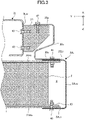
- FIG. 3 is a cross-sectional view taken along line A-A of FIG. 1 .
- a left side portion of the support device 10 suspended on the side rail 3L will be described by way of example with reference to the drawing.
- a right side portion of the support device 10 suspended on the side rail 3R is horizontally symmetrical to the left side portion of the support device 10 and has a similar configuration, and thus a detailed description thereof will be omitted.
- the battery pack 2 is placed on the under cover 23, and the front portion and the rear portion of the battery pack 2 are covered by the first brackets 21A and 21B, respectively.
- the first webs 21Aw and 21Bw and the first top flanges 21At and 21Bt of the first brackets 21A and 21B are in contact with corresponding faces of the battery pack 2 (the front side face 2a, the rear side face 2b, and a portion of the top face), respectively, and the first bottom flanges 21Ab and 21Bb are in contact with the under cover 23.
- the left second bracket 22L covers the under cover 23 and the first brackets 21A and 21B from the outside while leaving a space S between the left second bracket 22L and a left side face of the battery pack 2 in the vehicle width direction.
- the size of the space S can be adjusted by changing dimensions of the second top flange 22Lt and the second bottom flange 22Lb of the left second bracket 22L in the vehicle width direction, and can be adjusted also by changing dimensions of the first brackets 21A and 21B in the vehicle width direction.
- the second bottom flange 22Lb of the left second bracket 22L is in contact with the first bottom flanges 21Ab and 21Bb of the first brackets 21A and 21B.
- the second bottom flange 22Lb of the left second bracket 22L, the first bottom flanges 21Ab and 21Bb of the first brackets 21A and 21B, and the under cover 23 are coupled to one another with a plurality of bolts 40 (only one bolt is illustrated in FIG. 3 ).
- the second top flange 22Lt of the left second bracket 22L is in contact with the first top flanges 21At and 21Bt of the first brackets 21A and 21B, and the frame bracket 30.
- the second top flange 22Lt of the left second bracket 22L, the first top flanges 21At and 21Bt of the first brackets 21A and 21B, and a lower portion 30c of the frame bracket 30 are coupled to one another with a plurality of bolts 41 (only one bolt is illustrated in FIG. 3 ).
- the frame bracket 30 is, for example, a member including an upper portion 30a, a central portion 30b, and the lower portion 30c, and having an "S" shaped cross section as illustrated in the drawing.
- a rib (not shown) is provided on a side face of the frame bracket 30 to increase strength.
- the upper portion 30a of the frame bracket 30 is coupled to a mount 31 with a plurality of bolts 42 (only one bolt is illustrated in FIG. 3 ).
- the mount 31 is a member connecting the frame bracket 30 and the side rail 3L to each other.
- the mount 31 is coupled to a web 3Lw of the side rail 3L with a plurality of bolts 43 (only two bolts are illustrated in FIG. 3 ).
- the mount 31 is, for example, a rubber mount, and includes an elastic material such as rubber therein to elastically hold the frame bracket 30 with respect to the side rail 3L.
- the support device 10 has a structure in which the first brackets 21A and 21B having rigidity substantially equivalent to the chassis frame are longer than the long sides of the front side face 2a and the rear side face 2b of the battery pack 2, and cover the front side face 2a and the rear side face 2b to prevent an impact from being directly transferred to the battery pack 2 even when the impact is applied from a lateral side in the vehicle width direction.
- the second brackets 22L and 22R cover end portions of the first brackets 21A and 21B in the vehicle width direction, so that it is possible to improve torsional rigidity of the battery bracket 20 and substantially prevent fragments or the like from directly reaching the battery pack 2 even when an object collides from a lateral side in the vehicle width direction.
- the battery bracket 20 including the first brackets 21A and 21B and the second brackets 22L and 22R can be easily formed so as to fit the shape of the battery pack 2. Further, the battery bracket 20 is coupled to the side rails 3L and 3R via the frame bracket 30 to support the battery pack 2, so that the battery pack 2 that has a size larger than the distance between the side rails 3L and 3R of the electric truck can be easily mounted, and that torsional rigidity and side collision safety of the battery pack 2 can be secured.
- the first top flange 21At and the first bottom flange 21Ab are integrally and continuously formed with the first web 21Aw covering the front side face 2a of the battery pack 2, so that it is possible to cushion an impact applied from the front side of the vehicle, and improve front collision safety of the battery pack.
- the second brackets 22L and 22R include the second top flanges 22Lt and 22Rt coupled to the first top flanges 21At and 21Bt, and the second bottom flanges 22Lb and 22Rb coupled to the first bottom flanges 21Ab and 21Bb of the first brackets 21A and 21B, and thus have a structure of sandwiching and holding the first brackets 21A and 21B. As a result, it is possible to improve torsional rigidity of the battery bracket 20.
- the second top flanges 22Lt and 22Rt and the second bottom flanges 22Lb and 22Rb of the second brackets 22L and 22R are each formed to have a larger dimension in the vehicle width direction at an end portion in the longitudinal direction of the vehicle than that of a central portion. It is thus possible to reduce weight of the battery bracket 20 and secure torsional rigidity of the battery bracket 20.
- the space S is formed between the second webs 22Lw and 22Rw of the second brackets 22L and 22R, and side faces of the battery pack 2 in the vehicle width direction. It is thus possible to substantially prevent a situation in which even when the second brackets 22L and 22R are deformed due to an impact applied from the side of the vehicle, the second brackets 22L and 22R directly come into contact with the battery pack 2 and transfer the impact.
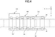
- FIG. 4 is a schematic top view of a vehicle including a vehicle battery pack support device according to another embodiment.
- three battery packs 2A, 2B, and 2C are arranged in a longitudinal direction of the vehicle and supported by support devices 10A, 10B, and 10C, respectively.
- the battery pack 2B and the support device 10B arranged at the center in the longitudinal direction of the vehicle are similar to those of the embodiment described above, whereas the battery pack 2A and the support device 10A arranged at a front side of the vehicle each have a longer dimension in the vehicle width direction and are offset toward the right side of the vehicle.
- the battery pack 2C and the support device 10C arranged at a rear side of the vehicle each have a longer dimension in the longitudinal direction of the vehicle than those of the central battery pack 2B and the support device 10B.
- the support devices 10A, 10B, and 10C can easily fit the shapes or layouts of the battery packs 2A, 2B, and 2C, respectively. It is thus possible to obtain similar effects to those of the embodiment described above.
- front and rear first brackets 21A and 21B of the battery bracket 20 are paired according to the embodiment described above, but are not limited thereto.
- two bracket members each having an "L" shaped cross section may be vertically combined to function as one of the first brackets.
- the pair of front and rear first brackets 21A and 21B may be integrally formed in a cylindrical shape. This configuration further improves torsional rigidity of the battery bracket 20.
Landscapes
- Engineering & Computer Science (AREA)
- Chemical & Material Sciences (AREA)
- Combustion & Propulsion (AREA)
- Transportation (AREA)
- Mechanical Engineering (AREA)
- Chemical Kinetics & Catalysis (AREA)
- Electrochemistry (AREA)
- General Chemical & Material Sciences (AREA)
- Aviation & Aerospace Engineering (AREA)
- Body Structure For Vehicles (AREA)
- Arrangement Or Mounting Of Propulsion Units For Vehicles (AREA)
- Battery Mounting, Suspending (AREA)
Abstract
Description
- The present invention relates to a vehicle battery pack support device.
- In recent years, from the viewpoint of an environmental impact, electric vehicles are under development also in the field of commercial vehicles such as trucks (Patent Document 1). It is desirable that a battery pack mounted in such an electric truck is arranged between frames in terms of securing side collision safety of the battery pack.
- PATENT DOCUMENT 1:
Japanese Unexamined Patent Publication No. 2016-113063 - However, there are various sizes of battery packs for running a vehicle and some of the battery packs are too large to fit between a pair of frames of the electric truck. In a case of employing such a battery pack, it is not possible to arrange the battery pack between frames.
- In addition, there is a demand to employ a common battery pack used in passenger cars for electric trucks in order to reduce costs. However, in case of passenger cars, the battery pack is mounted inside a vehicle body, but in case of electric trucks, the battery pack is arranged so as to be exposed to the outside.
- Under these circumstances, the present invention was made to provide a vehicle battery pack support device capable of securing torsional rigidity and side collision safety of a battery pack when a battery pack having a dimension that does not fit between frames of an electric truck is mounted.
- The present invention was made to overcome at least some of the problems described above, and can be implemented as the following embodiments or application examples.
- (1) A vehicle battery pack support device according to an application example is a support device for a battery pack that is mounted below a pair of side rails extending in a longitudinal direction of a vehicle and has a pair of side faces each facing in the longitudinal direction of the vehicle, the side faces each having a long side that is orthogonal to the longitudinal direction of the vehicle and extends beyond the side rails in a vehicle width direction, the vehicle battery pack support device comprising: a battery bracket for housing the battery pack; and a frame bracket for coupling the side rails and the battery bracket, the battery bracket including a first bracket covering the side faces of the battery pack, at least a portion of a top face that is continuous with the side faces, and at least a portion of a bottom face that is continuous with the side faces, the first bracket having a dimension in the vehicle width direction which is equal to or larger than the long side of the battery pack, and a second bracket covering an end portion of the first bracket in the vehicle width direction and coupled to the frame bracket.
- As described above, the vehicle battery pack support device has a structure in which the first brackets are longer than the long sides of the front side face and the rear side face of the battery pack, and cover the front side face and the rear side face to prevent an impact from being directly transferred to the battery pack even when the impact is applied from a lateral side in the vehicle width direction.
- In addition, the second brackets cover end portions of the first brackets in the vehicle width direction, so that it is possible to improve torsional rigidity of the battery bracket and substantially prevent fragments or the like from directly reaching the battery pack even when an object collides from a lateral side in the vehicle width direction.
- The battery bracket including the first brackets and the second brackets can be easily formed so as to fit the shape of the battery pack. Further, the battery bracket is coupled to the side rails via the frame bracket to support the battery pack, so that the battery pack that has a size larger than the distance between the frames of the electric truck can be easily mounted, and that torsional rigidity and side collision safety of the battery pack can be secured.
- (2) In the vehicle battery pack support device according to the application example of the above configuration (1), the first bracket may include: a first web that covers the side face of the battery pack facing a front side of the vehicle; a first top flange that is continuous with the first web and covers the top face; and a first bottom flange that is continuous with the first web and covers the bottom face. It is thus possible to cushion an impact applied from the front side of the vehicle, and improve front collision safety of the battery pack.
- (3) In the vehicle battery pack support device according to the application example of the above configuration (1), the first bracket may have a cylindrical shape integrally covering the side faces, the top face, and the bottom face. This configuration can further improve torsional rigidity of the battery bracket.
- (4) In the vehicle battery pack support device according to the application example of any one of the above configurations (1) to (3), the second bracket may include: a second top flange coupled to the first top flange of the first bracket; a second bottom flange coupled to the first bottom flange of the first bracket; and a second web coupling the second top flange and the second bottom flange. Therefore, the second bracket has a structure of sandwiching and holding the first bracket, which makes it possible to improve torsional rigidity of the battery bracket.
- (5) In the vehicle battery pack support device according to the application example of the above configuration (4), at least one of the second top flange or the second bottom flange of the second bracket may be formed to have a larger dimension in the vehicle width direction at an end portion in the longitudinal direction of the vehicle than that of a central portion. It is thus possible to reduce weight of the battery bracket and secure torsional rigidity of the battery bracket.
- (6) In the vehicle battery pack support device according to the application example of the above configuration (4), a space may be formed between the second web of the second bracket and a side face of the battery pack in the vehicle width direction. It is thus possible to substantially prevent a situation in which even when the second brackets are deformed due to an impact applied from the side of the vehicle, the second brackets directly come into contact with the battery pack and transfer the impact.
-
-
FIG. 1 is a schematic top view illustrating an overall configuration of a vehicle including a vehicle battery pack support device according to an embodiment. -
FIG. 2 is an exploded perspective view of a battery pack and a battery bracket. -
FIG. 3 is a cross-sectional view taken along line A-A ofFIG. 1 . -
FIG. 4 is a schematic top view illustrating an overall configuration of a vehicle including a vehicle battery pack support device according to another embodiment. - An embodiment of the present invention will be described in detail below with reference to the drawings. The drawings are not necessarily to scale.
FIG. 1 is a schematic top view illustrating an overall configuration of a vehicle including a vehicle battery pack support device according to the present embodiment. The shapes of components described below are, basically, horizontally symmetrical with respect to the center of thevehicle 1 in a vehicle width direction (Y direction in the drawings). Therefore, basically, only one of left and right components is described in the following description, but the other components which are symmetrical to their counterparts have the same shapes as their counterparts. - The
vehicle 1 includes a motor (electric motor) (not shown) as a driving power source, and is, for example, a so-called electric vehicle. In the present embodiment in particular, thevehicle 1 is a truck vehicle provided with acab 4 and acargo box 6. Thecab 4 is mounted on a chassis frame, and is adapted for a driver to board. Thecargo box 6 is disposed behind thecab 4 and is configured to be capable of carrying the cargo. In the drawing, thecab 4 and thecargo box 6 are outlined with a dotted line. - The
vehicle 1 may also be a hybrid car including an engine in addition to a motor as the driving power source. Further, thevehicle 1 is not limited to the truck vehicle, and may be any other commercial vehicle including a battery for driving the vehicle. - The chassis frame is what is called a ladder frame including a pair of
side rails cross members side rails - Further,
front wheels 7 are suspended at a front portion of the chassis frame andrear wheels 8 are suspended at a rear portion of the chassis frame. A driving force is transmitted to these wheels by the motor (not shown) such that thevehicle 1 can travel. A battery for feeding power to the motor as such a driving power source is mounted in thevehicle 1 via asupport device 10. - The battery has a configuration in which a battery unit (not shown) including a plurality of secondary battery cells is housed in a
battery pack 2 which is a casing. Thebattery pack 2 is supported on theside rails support device 10 as illustrated inFIG. 1 . - The
support device 10 includes abattery bracket 20 and aframe bracket 30. - The
battery bracket 20 includes a pair of frontfirst bracket 21A and rearfirst bracket 21B (also collectively referred to asfirst brackets second bracket 22L and rightsecond bracket 22R (also collectively referred to assecond brackets - A front portion and a rear portion of the
second bracket 22L of thebattery bracket 20 are coupled to and supported on theside rail 3L via theframe bracket 30, and a front portion and a rear portion of thesecond bracket 22R of thebattery bracket 20 are coupled to and supported on theside rail 3R via theframe bracket 30. -
FIG. 2 is an exploded perspective view of the battery pack and the battery bracket. Thebattery pack 2 is formed in a rectangular parallelepiped shape and has afront side face 2a which is a rectangular side face facing a front side of the vehicle, and arear side face 2b which is a rectangular shape facing a rear side of the vehicle. Thebattery pack 2 is arranged along the vehicle width direction (Y direction in the drawings) so that long sides of thefront side face 2a and therear side face 2b are orthogonal to the longitudinal direction (X direction in the drawings) of the vehicle. Thebattery pack 2 is dimensioned so that both end portions of thebattery pack 2 in the vehicle width direction extend beyond outer side faces of theside rails front side face 2a and therear side face 2b is larger than a length L1 between theside rails - An under
cover 23 is a member on which thebattery pack 2 is directly placed, and is implemented by, for example, a plate-shaped member. The undercover 23 is a cover that simply covers a bottom face of thebattery pack 2, and it is thefirst brackets battery pack 2. - The front
first bracket 21A includes a first web 21Aw for covering thefront side face 2a of thebattery pack 2 in the drawing. Further, a first top flange 21At for covering a portion of a top face which is continuous with thefront side face 2a of thebattery pack 2, and a first bottom flange 21Ab for covering a portion of the bottom face which is continuous with thefront side face 2a are formed so as to be vertically continuous with the first web 21Aw. In other words, the first top flange 21At and the first bottom flange 21Ab are arranged so that flat surface portions thereof face each other in a vehicle height direction (Z direction in the drawings). Thus, the frontfirst bracket 21A is formed in a substantial "U" shape having a cross section that is open toward the rear side of the vehicle. - Similarly, the rear
first bracket 21B includes a first web 21Bw for covering therear side face 2b of thebattery pack 2. Further, the rearfirst bracket 21B includes a first top flange 21Bt for covering a portion of the top face which is continuous with therear side face 2b of thebattery pack 2, and a first bottom flange 21Bb for covering a portion of the bottom face which is continuous with therear side face 2b. In other words, the first top flange 21Bt and the first bottom flange 21Bb of the rearfirst bracket 21B are arranged so that flat surface portions thereof face each other in the vehicle height direction (Z direction in the drawings). Thus, the rearfirst bracket 21B is formed in a substantial "U" shape having a cross section that is open toward the front side of the vehicle. - The open side of the
first bracket 21A and the open side of thefirst bracket 21B face each other, and thefirst brackets battery pack 2 while sandwiching thebattery pack 2 therebetween in the longitudinal direction of the vehicle. - The left
second bracket 22L includes a second web 22Lw covering open faces of left end portions of thefirst brackets first brackets first brackets first brackets first brackets - The second top flange 22Lt and the second bottom flange 22Lb of the left
second bracket 22L are each formed to have a larger dimension in the vehicle width direction at an end portion in the longitudinal direction of the vehicle than that of a central portion. Specifically, a central portion of each of the second top flange 22Lt and the second bottom flange 22Lb in the longitudinal direction of the vehicle is cut out in an arc shape. By doing so, torsional rigidity of a battery pack support device is improved while achieving weight reduction. - The right
second bracket 22R is horizontally symmetrical to the leftsecond bracket 22L and has a similar configuration, and thus a description thereof will be omitted. - In the drawing, when portions connected by a dot-and-dash line are aligned with each other, the
battery bracket 20 surrounds four side faces and portions of the top face and the bottom face of thebattery pack 2, like a box. Thebattery bracket 20 surrounding thebattery pack 2 as described above is coupled to the side rails 3L and 3R via theframe bracket 30. - Referring to
FIG. 3, FIG. 3 is a cross-sectional view taken along line A-A ofFIG. 1 . Hereinafter, a left side portion of thesupport device 10 suspended on theside rail 3L will be described by way of example with reference to the drawing. A right side portion of thesupport device 10 suspended on theside rail 3R is horizontally symmetrical to the left side portion of thesupport device 10 and has a similar configuration, and thus a detailed description thereof will be omitted. - As described above, the
battery pack 2 is placed on theunder cover 23, and the front portion and the rear portion of thebattery pack 2 are covered by thefirst brackets first brackets front side face 2a, therear side face 2b, and a portion of the top face), respectively, and the first bottom flanges 21Ab and 21Bb are in contact with theunder cover 23. - In addition, the left
second bracket 22L covers theunder cover 23 and thefirst brackets second bracket 22L and a left side face of thebattery pack 2 in the vehicle width direction. The size of the space S can be adjusted by changing dimensions of the second top flange 22Lt and the second bottom flange 22Lb of the leftsecond bracket 22L in the vehicle width direction, and can be adjusted also by changing dimensions of thefirst brackets - The second bottom flange 22Lb of the left
second bracket 22L is in contact with the first bottom flanges 21Ab and 21Bb of thefirst brackets second bracket 22L, the first bottom flanges 21Ab and 21Bb of thefirst brackets under cover 23 are coupled to one another with a plurality of bolts 40 (only one bolt is illustrated inFIG. 3 ). - The second top flange 22Lt of the left
second bracket 22L is in contact with the first top flanges 21At and 21Bt of thefirst brackets frame bracket 30. The second top flange 22Lt of the leftsecond bracket 22L, the first top flanges 21At and 21Bt of thefirst brackets lower portion 30c of theframe bracket 30 are coupled to one another with a plurality of bolts 41 (only one bolt is illustrated inFIG. 3 ). - The
frame bracket 30 is, for example, a member including anupper portion 30a, acentral portion 30b, and thelower portion 30c, and having an "S" shaped cross section as illustrated in the drawing. A rib (not shown) is provided on a side face of theframe bracket 30 to increase strength. Theupper portion 30a of theframe bracket 30 is coupled to amount 31 with a plurality of bolts 42 (only one bolt is illustrated inFIG. 3 ). - The
mount 31 is a member connecting theframe bracket 30 and theside rail 3L to each other. For example, themount 31 is coupled to a web 3Lw of theside rail 3L with a plurality of bolts 43 (only two bolts are illustrated inFIG. 3 ). Themount 31 is, for example, a rubber mount, and includes an elastic material such as rubber therein to elastically hold theframe bracket 30 with respect to theside rail 3L. - As described above, the
support device 10 has a structure in which thefirst brackets front side face 2a and therear side face 2b of thebattery pack 2, and cover thefront side face 2a and therear side face 2b to prevent an impact from being directly transferred to thebattery pack 2 even when the impact is applied from a lateral side in the vehicle width direction. - In addition, the
second brackets first brackets battery bracket 20 and substantially prevent fragments or the like from directly reaching thebattery pack 2 even when an object collides from a lateral side in the vehicle width direction. - The
battery bracket 20 including thefirst brackets second brackets battery pack 2. Further, thebattery bracket 20 is coupled to the side rails 3L and 3R via theframe bracket 30 to support thebattery pack 2, so that thebattery pack 2 that has a size larger than the distance between the side rails 3L and 3R of the electric truck can be easily mounted, and that torsional rigidity and side collision safety of thebattery pack 2 can be secured. - Particularly, in the front
first bracket 21A, the first top flange 21At and the first bottom flange 21Ab are integrally and continuously formed with the first web 21Aw covering thefront side face 2a of thebattery pack 2, so that it is possible to cushion an impact applied from the front side of the vehicle, and improve front collision safety of the battery pack. - Further, the
second brackets first brackets first brackets battery bracket 20. - In addition, the second top flanges 22Lt and 22Rt and the second bottom flanges 22Lb and 22Rb of the
second brackets battery bracket 20 and secure torsional rigidity of thebattery bracket 20. - Further, the space S is formed between the second webs 22Lw and 22Rw of the
second brackets battery pack 2 in the vehicle width direction. It is thus possible to substantially prevent a situation in which even when thesecond brackets second brackets battery pack 2 and transfer the impact. - Although the description of the embodiment of the vehicle battery pack support device of the present invention ends here, the present invention is not limited to this embodiment.
- For example,
FIG. 4 is a schematic top view of a vehicle including a vehicle battery pack support device according to another embodiment. According to this embodiment, as illustrated inFIG. 4 , threebattery packs support devices - The
battery pack 2B and thesupport device 10B arranged at the center in the longitudinal direction of the vehicle are similar to those of the embodiment described above, whereas thebattery pack 2A and thesupport device 10A arranged at a front side of the vehicle each have a longer dimension in the vehicle width direction and are offset toward the right side of the vehicle. The battery pack 2C and the support device 10C arranged at a rear side of the vehicle each have a longer dimension in the longitudinal direction of the vehicle than those of thecentral battery pack 2B and thesupport device 10B. - The
support devices - Further, the front and rear
first brackets battery bracket 20 are paired according to the embodiment described above, but are not limited thereto. For example, two bracket members each having an "L" shaped cross section may be vertically combined to function as one of the first brackets. Alternatively, the pair of front and rearfirst brackets battery bracket 20. - Although the embodiments of the present invention have been described above, the present invention can be implemented in various other forms, and various omissions, replacements, and changes can be made without departing from the spirit of the present invention. The embodiments and variations are included in the scope and spirit of the invention, as well as in the invention of claims and the equivalents thereof.
-
- 1
- Vehicle
- 2, 2A, 2B, 2C
- Battery Pack
- 3L, 3R
- Side Rail
- 10, 10A, 10B, 10C
- Support Device
- 20
- Battery Bracket
- 21A, 21B
- First Bracket
- 22L, 22R
- Second Bracket
- 23
- Under Cover
- 30
- Frame Bracket
- 31
- Mount
Claims (6)
- A vehicle battery pack support device for a battery pack that is mounted below a pair of side rails extending in a longitudinal direction of a vehicle and has a pair of side faces each facing in the longitudinal direction of the vehicle, the side faces each having a long side that is orthogonal to the longitudinal direction of the vehicle and extends beyond the side rails in a vehicle width direction, the vehicle battery pack support device comprising:a battery bracket for housing the battery pack; anda frame bracket for coupling the side rails and the battery bracket,the battery bracket includinga first bracket covering the side faces of the battery pack, at least a portion of a top face that is continuous with the side faces, and at least a portion of a bottom face that is continuous with the side faces, the first bracket having a dimension in the vehicle width direction which is equal to or larger than the long side of the battery pack, anda second bracket covering an end portion of the first bracket in the vehicle width direction and coupled to the frame bracket.
- The vehicle battery pack support device of claim 1, wherein
the first bracket includes: a first web that covers the side face of the battery pack facing a front side of the vehicle; a first top flange that is continuous with the first web and covers the top face; and a first bottom flange that is continuous with the first web and covers the bottom face. - The vehicle battery pack support device of claim 1, wherein
the first bracket has a cylindrical shape integrally covering the side faces, the top face, and the bottom face. - The vehicle battery pack support device of any one of claims 1 to 3, wherein
the second bracket includes: a second top flange coupled to the first top flange of the first bracket; a second bottom flange coupled to the first bottom flange of the first bracket; and a second web coupling the second top flange and the second bottom flange. - The vehicle battery pack support device of claim 4, wherein
at least one of the second top flange or the second bottom flange of the second bracket is formed to have a larger dimension in the vehicle width direction at an end portion in the longitudinal direction of the vehicle than that of a central portion. - The vehicle battery pack support device of claim 4, wherein
a space is formed between the second web of the second bracket and a side face of the battery pack in the vehicle width direction.
Applications Claiming Priority (2)
| Application Number | Priority Date | Filing Date | Title |
|---|---|---|---|
| JP2019217198A JP7413739B2 (en) | 2019-11-29 | 2019-11-29 | Vehicle battery pack support device |
| PCT/JP2020/038377 WO2021106391A1 (en) | 2019-11-29 | 2020-10-09 | Battery pack support device for vehicle |
Publications (3)
| Publication Number | Publication Date |
|---|---|
| EP4063239A1 true EP4063239A1 (en) | 2022-09-28 |
| EP4063239A4 EP4063239A4 (en) | 2023-02-08 |
| EP4063239B1 EP4063239B1 (en) | 2024-12-04 |
Family
ID=76088300
Family Applications (1)
| Application Number | Title | Priority Date | Filing Date |
|---|---|---|---|
| EP20894134.4A Active EP4063239B1 (en) | 2019-11-29 | 2020-10-09 | Vehicle with a battery pack support device |
Country Status (5)
| Country | Link |
|---|---|
| US (1) | US12403757B2 (en) |
| EP (1) | EP4063239B1 (en) |
| JP (1) | JP7413739B2 (en) |
| CN (1) | CN114746326B (en) |
| WO (1) | WO2021106391A1 (en) |
Families Citing this family (11)
| Publication number | Priority date | Publication date | Assignee | Title |
|---|---|---|---|---|
| JP7525365B2 (en) * | 2020-10-09 | 2024-07-30 | ダイムラー トラック エージー | Battery pack support device and electric truck |
| EP3981631B1 (en) * | 2020-10-12 | 2024-12-18 | Volvo Truck Corporation | A battery assembly |
| JP7714388B2 (en) * | 2021-06-30 | 2025-07-29 | ダイムラー トラック エージー | Support device for vehicle battery pack |
| JP7714389B2 (en) * | 2021-06-30 | 2025-07-29 | ダイムラー トラック エージー | Support device for vehicle battery pack |
| JP7775539B2 (en) * | 2021-07-21 | 2025-11-26 | メルセデス・ベンツ グループ アクチェンゲゼルシャフト | Truck vehicle |
| JP7804534B2 (en) * | 2022-05-26 | 2026-01-22 | ダイムラー トラック エージー | Drive battery support device |
| JP2023173570A (en) * | 2022-05-26 | 2023-12-07 | ダイムラー トラック エージー | Drive battery support device |
| JP7666480B2 (en) * | 2022-10-11 | 2025-04-22 | トヨタ自動車株式会社 | Battery mounting structure for frame vehicles |
| JP7694527B2 (en) * | 2022-10-11 | 2025-06-18 | トヨタ自動車株式会社 | Battery mounting structure for frame vehicles |
| CN115891607A (en) * | 2022-11-29 | 2023-04-04 | 东风汽车股份有限公司 | A CTC battery pack for skateboard chassis |
| EP4656427A1 (en) * | 2024-05-27 | 2025-12-03 | Volvo Truck Corporation | Battery pack support system |
Family Cites Families (28)
| Publication number | Priority date | Publication date | Assignee | Title |
|---|---|---|---|---|
| JP5807476B2 (en) * | 2011-09-22 | 2015-11-10 | 日産自動車株式会社 | Electric vehicle battery pack support structure |
| JP5966824B2 (en) * | 2012-09-28 | 2016-08-10 | 三菱自動車工業株式会社 | Track-type electric vehicle frame structure |
| JP6136187B2 (en) * | 2012-10-16 | 2017-05-31 | トヨタ自動車株式会社 | Battery mounting structure for vehicles |
| CN104802860B (en) * | 2014-01-27 | 2019-06-07 | 比亚迪股份有限公司 | The chassis assembly and electric truck of electric truck |
| JP2016113063A (en) | 2014-12-16 | 2016-06-23 | ダイムラー・アクチェンゲゼルシャフトDaimler AG | Battery box-holding structure |
| JP6520808B2 (en) | 2016-04-21 | 2019-05-29 | トヨタ自動車株式会社 | Vehicle battery mounting structure |
| JP6512163B2 (en) | 2016-04-21 | 2019-05-15 | トヨタ自動車株式会社 | Vehicle battery mounting structure |
| DE102016113759A1 (en) * | 2016-07-26 | 2017-04-20 | Daimler Ag | Fastening arrangement of a battery device to a frame of a commercial vehicle |
| US10112470B2 (en) * | 2017-01-11 | 2018-10-30 | GM Global Technology Operations LLC | Structural enhancements of an electric vehicle |
| JP2018118673A (en) * | 2017-01-26 | 2018-08-02 | 日産ライトトラック株式会社 | Vehicle battery support structure |
| JP6848543B2 (en) | 2017-03-07 | 2021-03-24 | 三菱自動車工業株式会社 | Body structure of electric vehicle |
| US10637023B2 (en) * | 2017-09-06 | 2020-04-28 | Benteler Automobiltechnik Gmbh | Battery carrier for an electric motor vehicle |
| US10640005B2 (en) * | 2017-09-15 | 2020-05-05 | Ford Global Technologies, Llc | Bracket attachment structure having an internal plate |
| JP7067142B2 (en) * | 2018-03-09 | 2022-05-16 | トヨタ自動車株式会社 | Vehicle undercarriage |
| JP6667563B2 (en) | 2018-03-19 | 2020-03-18 | 本田技研工業株式会社 | Body rear structure |
| DE102018205234B3 (en) * | 2018-04-06 | 2019-08-08 | Ford Global Technologies, Llc | Battery assembly for an electric or hybrid electric vehicle |
| JP7163059B2 (en) * | 2018-04-27 | 2022-10-31 | メルセデス・ベンツ グループ アクチェンゲゼルシャフト | Vehicle battery housing, vehicle battery pack, and electric vehicle |
| JP7057712B2 (en) | 2018-04-27 | 2022-04-20 | ダイムラー・アクチェンゲゼルシャフト | Vehicle battery pack support |
| CA3110459C (en) * | 2018-08-24 | 2024-06-18 | Hexagon Purus North America Holdings Inc. | Battery system for heavy duty vehicles |
| JP2020035717A (en) * | 2018-08-31 | 2020-03-05 | 本田技研工業株式会社 | Battery pack and method of manufacturing battery pack |
| JP7225257B2 (en) * | 2018-09-20 | 2023-02-20 | 三洋電機株式会社 | Power supply device, vehicle equipped with power supply device, and power storage device |
| US10493837B1 (en) * | 2018-10-11 | 2019-12-03 | Paccar Inc | Chassis mounted assemblies for electric or hybrid vehicles |
| US11040610B2 (en) * | 2019-04-19 | 2021-06-22 | Hexagon Purus North America Holdings Inc. | Electric powertrain system for heavy duty vehicles |
| FR3099457A1 (en) * | 2019-07-31 | 2021-02-05 | Faurecia Systemes D'echappement | Vehicle chassis and associated vehicle |
| DE102019124066B4 (en) * | 2019-09-09 | 2022-11-24 | Kirchhoff Automotive Deutschland Gmbh | frame structure |
| JP7422518B2 (en) * | 2019-11-06 | 2024-01-26 | ダイムラー トラック エージー | Support device for vehicle battery pack and electric vehicle |
| US11124076B1 (en) * | 2020-11-30 | 2021-09-21 | Nikola Corporation | Electric vehicle battery frame assembly |
| CA3227982A1 (en) * | 2021-08-26 | 2023-03-02 | Hexagon Purus North America Holdings Inc. | Battery packs for utility vehicle electric drivetrains |
-
2019
- 2019-11-29 JP JP2019217198A patent/JP7413739B2/en active Active
-
2020
- 2020-10-09 CN CN202080082755.4A patent/CN114746326B/en active Active
- 2020-10-09 EP EP20894134.4A patent/EP4063239B1/en active Active
- 2020-10-09 WO PCT/JP2020/038377 patent/WO2021106391A1/en not_active Ceased
- 2020-10-09 US US17/780,780 patent/US12403757B2/en active Active
Also Published As
| Publication number | Publication date |
|---|---|
| US12403757B2 (en) | 2025-09-02 |
| EP4063239A4 (en) | 2023-02-08 |
| JP7413739B2 (en) | 2024-01-16 |
| WO2021106391A1 (en) | 2021-06-03 |
| CN114746326A (en) | 2022-07-12 |
| CN114746326B (en) | 2024-01-12 |
| EP4063239B1 (en) | 2024-12-04 |
| JP2021084605A (en) | 2021-06-03 |
| US20220410686A1 (en) | 2022-12-29 |
Similar Documents
| Publication | Publication Date | Title |
|---|---|---|
| EP4063239B1 (en) | Vehicle with a battery pack support device | |
| CN112020448B (en) | Supporting device for vehicle battery pack | |
| US12220979B2 (en) | Support device for vehicle battery pack and electric vehicle | |
| US11975600B2 (en) | Electric truck | |
| JP2016113063A (en) | Battery box-holding structure | |
| EP4368455A1 (en) | Truck vehicle | |
| WO2019208749A1 (en) | Vehicular battery housing, vehicular battery pack, and electric vehicle | |
| JP2015137001A (en) | Electric vehicle | |
| JP2022025814A (en) | Support device of vehicular battery pack | |
| JP7283006B2 (en) | electric truck | |
| JP2021133863A (en) | Electric vehicle | |
| JP2022038552A (en) | Electrically-driven truck | |
| WO2022049939A1 (en) | Support device for vehicle battery pack | |
| JP2023090428A (en) | Battery pack support device | |
| JP2018108787A (en) | Battery protection device of electric vehicle | |
| US12391131B2 (en) | Electric truck | |
| CN204586750U (en) | The mounting structure of on-vehicle battery | |
| WO2019244858A1 (en) | Vehicular battery pack support device | |
| JP2022085063A (en) | Battery pack support device | |
| WO2022191264A1 (en) | Chassis | |
| JP2025021687A (en) | Drive battery mounting structure | |
| CN119459886A (en) | The structure of the car body |
Legal Events
| Date | Code | Title | Description |
|---|---|---|---|
| STAA | Information on the status of an ep patent application or granted ep patent |
Free format text: STATUS: THE INTERNATIONAL PUBLICATION HAS BEEN MADE |
|
| PUAI | Public reference made under article 153(3) epc to a published international application that has entered the european phase |
Free format text: ORIGINAL CODE: 0009012 |
|
| STAA | Information on the status of an ep patent application or granted ep patent |
Free format text: STATUS: REQUEST FOR EXAMINATION WAS MADE |
|
| 17P | Request for examination filed |
Effective date: 20220622 |
|
| AK | Designated contracting states |
Kind code of ref document: A1 Designated state(s): AL AT BE BG CH CY CZ DE DK EE ES FI FR GB GR HR HU IE IS IT LI LT LU LV MC MK MT NL NO PL PT RO RS SE SI SK SM TR |
|
| RAP1 | Party data changed (applicant data changed or rights of an application transferred) |
Owner name: DAIMLER TRUCK AG |
|
| A4 | Supplementary search report drawn up and despatched |
Effective date: 20230109 |
|
| RIC1 | Information provided on ipc code assigned before grant |
Ipc: H01M 50/249 20210101ALN20230103BHEP Ipc: H01M 50/244 20210101ALN20230103BHEP Ipc: B62D 21/09 19850101ALN20230103BHEP Ipc: B62D 21/15 19850101ALI20230103BHEP Ipc: B60K 1/04 19680901ALI20230103BHEP Ipc: H01M 50/20 20210101ALI20230103BHEP Ipc: B62D 21/02 19680901AFI20230103BHEP |
|
| DAV | Request for validation of the european patent (deleted) | ||
| DAX | Request for extension of the european patent (deleted) | ||
| STAA | Information on the status of an ep patent application or granted ep patent |
Free format text: STATUS: EXAMINATION IS IN PROGRESS |
|
| 17Q | First examination report despatched |
Effective date: 20231109 |
|
| GRAP | Despatch of communication of intention to grant a patent |
Free format text: ORIGINAL CODE: EPIDOSNIGR1 |
|
| GRAP | Despatch of communication of intention to grant a patent |
Free format text: ORIGINAL CODE: EPIDOSNIGR1 |
|
| STAA | Information on the status of an ep patent application or granted ep patent |
Free format text: STATUS: GRANT OF PATENT IS INTENDED |
|
| RIC1 | Information provided on ipc code assigned before grant |
Ipc: H01M 50/249 20210101ALN20240529BHEP Ipc: H01M 50/244 20210101ALN20240529BHEP Ipc: B62D 21/09 20060101ALN20240529BHEP Ipc: B62D 21/15 20060101ALI20240529BHEP Ipc: B60K 1/04 20190101ALI20240529BHEP Ipc: H01M 50/20 20210101ALI20240529BHEP Ipc: B62D 21/02 20060101AFI20240529BHEP |
|
| INTG | Intention to grant announced |
Effective date: 20240614 |
|
| GRAS | Grant fee paid |
Free format text: ORIGINAL CODE: EPIDOSNIGR3 |
|
| GRAA | (expected) grant |
Free format text: ORIGINAL CODE: 0009210 |
|
| STAA | Information on the status of an ep patent application or granted ep patent |
Free format text: STATUS: THE PATENT HAS BEEN GRANTED |
|
| P01 | Opt-out of the competence of the unified patent court (upc) registered |
Free format text: CASE NUMBER: APP_53436/2024 Effective date: 20240926 |
|
| AK | Designated contracting states |
Kind code of ref document: B1 Designated state(s): AL AT BE BG CH CY CZ DE DK EE ES FI FR GB GR HR HU IE IS IT LI LT LU LV MC MK MT NL NO PL PT RO RS SE SI SK SM TR |
|
| REG | Reference to a national code |
Ref country code: DE Ref legal event code: R081 Ref document number: 602020042777 Country of ref document: DE Owner name: DAIMLER TRUCK AG, DE Free format text: FORMER OWNER: ANMELDERANGABEN UNKLAR / UNVOLLSTAENDIG, 80297 MUENCHEN, DE Ref country code: CH Ref legal event code: EP |
|
| REG | Reference to a national code |
Ref country code: DE Ref legal event code: R096 Ref document number: 602020042777 Country of ref document: DE |
|
| REG | Reference to a national code |
Ref country code: IE Ref legal event code: FG4D |
|
| REG | Reference to a national code |
Ref country code: LT Ref legal event code: MG9D |
|
| REG | Reference to a national code |
Ref country code: NL Ref legal event code: MP Effective date: 20241204 |
|
| PG25 | Lapsed in a contracting state [announced via postgrant information from national office to epo] |
Ref country code: HR Free format text: LAPSE BECAUSE OF FAILURE TO SUBMIT A TRANSLATION OF THE DESCRIPTION OR TO PAY THE FEE WITHIN THE PRESCRIBED TIME-LIMIT Effective date: 20241204 |
|
| PG25 | Lapsed in a contracting state [announced via postgrant information from national office to epo] |
Ref country code: FI Free format text: LAPSE BECAUSE OF FAILURE TO SUBMIT A TRANSLATION OF THE DESCRIPTION OR TO PAY THE FEE WITHIN THE PRESCRIBED TIME-LIMIT Effective date: 20241204 |
|
| PG25 | Lapsed in a contracting state [announced via postgrant information from national office to epo] |
Ref country code: BG Free format text: LAPSE BECAUSE OF FAILURE TO SUBMIT A TRANSLATION OF THE DESCRIPTION OR TO PAY THE FEE WITHIN THE PRESCRIBED TIME-LIMIT Effective date: 20241204 |
|
| PG25 | Lapsed in a contracting state [announced via postgrant information from national office to epo] |
Ref country code: ES Free format text: LAPSE BECAUSE OF FAILURE TO SUBMIT A TRANSLATION OF THE DESCRIPTION OR TO PAY THE FEE WITHIN THE PRESCRIBED TIME-LIMIT Effective date: 20241204 |
|
| PG25 | Lapsed in a contracting state [announced via postgrant information from national office to epo] |
Ref country code: NO Free format text: LAPSE BECAUSE OF FAILURE TO SUBMIT A TRANSLATION OF THE DESCRIPTION OR TO PAY THE FEE WITHIN THE PRESCRIBED TIME-LIMIT Effective date: 20250304 |
|
| PG25 | Lapsed in a contracting state [announced via postgrant information from national office to epo] |
Ref country code: GR Free format text: LAPSE BECAUSE OF FAILURE TO SUBMIT A TRANSLATION OF THE DESCRIPTION OR TO PAY THE FEE WITHIN THE PRESCRIBED TIME-LIMIT Effective date: 20250305 Ref country code: LV Free format text: LAPSE BECAUSE OF FAILURE TO SUBMIT A TRANSLATION OF THE DESCRIPTION OR TO PAY THE FEE WITHIN THE PRESCRIBED TIME-LIMIT Effective date: 20241204 |
|
| PG25 | Lapsed in a contracting state [announced via postgrant information from national office to epo] |
Ref country code: RS Free format text: LAPSE BECAUSE OF FAILURE TO SUBMIT A TRANSLATION OF THE DESCRIPTION OR TO PAY THE FEE WITHIN THE PRESCRIBED TIME-LIMIT Effective date: 20250304 |
|
| PG25 | Lapsed in a contracting state [announced via postgrant information from national office to epo] |
Ref country code: NL Free format text: LAPSE BECAUSE OF FAILURE TO SUBMIT A TRANSLATION OF THE DESCRIPTION OR TO PAY THE FEE WITHIN THE PRESCRIBED TIME-LIMIT Effective date: 20241204 |
|
| REG | Reference to a national code |
Ref country code: AT Ref legal event code: MK05 Ref document number: 1747906 Country of ref document: AT Kind code of ref document: T Effective date: 20241204 |
|
| PG25 | Lapsed in a contracting state [announced via postgrant information from national office to epo] |
Ref country code: SM Free format text: LAPSE BECAUSE OF FAILURE TO SUBMIT A TRANSLATION OF THE DESCRIPTION OR TO PAY THE FEE WITHIN THE PRESCRIBED TIME-LIMIT Effective date: 20241204 |
|
| PG25 | Lapsed in a contracting state [announced via postgrant information from national office to epo] |
Ref country code: PL Free format text: LAPSE BECAUSE OF FAILURE TO SUBMIT A TRANSLATION OF THE DESCRIPTION OR TO PAY THE FEE WITHIN THE PRESCRIBED TIME-LIMIT Effective date: 20241204 |
|
| PG25 | Lapsed in a contracting state [announced via postgrant information from national office to epo] |
Ref country code: IS Free format text: LAPSE BECAUSE OF FAILURE TO SUBMIT A TRANSLATION OF THE DESCRIPTION OR TO PAY THE FEE WITHIN THE PRESCRIBED TIME-LIMIT Effective date: 20250404 |
|
| PG25 | Lapsed in a contracting state [announced via postgrant information from national office to epo] |
Ref country code: PT Free format text: LAPSE BECAUSE OF FAILURE TO SUBMIT A TRANSLATION OF THE DESCRIPTION OR TO PAY THE FEE WITHIN THE PRESCRIBED TIME-LIMIT Effective date: 20250404 |
|
| PG25 | Lapsed in a contracting state [announced via postgrant information from national office to epo] |
Ref country code: EE Free format text: LAPSE BECAUSE OF FAILURE TO SUBMIT A TRANSLATION OF THE DESCRIPTION OR TO PAY THE FEE WITHIN THE PRESCRIBED TIME-LIMIT Effective date: 20241204 |
|
| PG25 | Lapsed in a contracting state [announced via postgrant information from national office to epo] |
Ref country code: RO Free format text: LAPSE BECAUSE OF FAILURE TO SUBMIT A TRANSLATION OF THE DESCRIPTION OR TO PAY THE FEE WITHIN THE PRESCRIBED TIME-LIMIT Effective date: 20241204 Ref country code: AT Free format text: LAPSE BECAUSE OF FAILURE TO SUBMIT A TRANSLATION OF THE DESCRIPTION OR TO PAY THE FEE WITHIN THE PRESCRIBED TIME-LIMIT Effective date: 20241204 |
|
| PG25 | Lapsed in a contracting state [announced via postgrant information from national office to epo] |
Ref country code: SK Free format text: LAPSE BECAUSE OF FAILURE TO SUBMIT A TRANSLATION OF THE DESCRIPTION OR TO PAY THE FEE WITHIN THE PRESCRIBED TIME-LIMIT Effective date: 20241204 |
|
| PG25 | Lapsed in a contracting state [announced via postgrant information from national office to epo] |
Ref country code: CZ Free format text: LAPSE BECAUSE OF FAILURE TO SUBMIT A TRANSLATION OF THE DESCRIPTION OR TO PAY THE FEE WITHIN THE PRESCRIBED TIME-LIMIT Effective date: 20241204 |
|
| PG25 | Lapsed in a contracting state [announced via postgrant information from national office to epo] |
Ref country code: IT Free format text: LAPSE BECAUSE OF FAILURE TO SUBMIT A TRANSLATION OF THE DESCRIPTION OR TO PAY THE FEE WITHIN THE PRESCRIBED TIME-LIMIT Effective date: 20241204 |
|
| REG | Reference to a national code |
Ref country code: DE Ref legal event code: R097 Ref document number: 602020042777 Country of ref document: DE |
|
| PG25 | Lapsed in a contracting state [announced via postgrant information from national office to epo] |
Ref country code: SE Free format text: LAPSE BECAUSE OF FAILURE TO SUBMIT A TRANSLATION OF THE DESCRIPTION OR TO PAY THE FEE WITHIN THE PRESCRIBED TIME-LIMIT Effective date: 20241204 |
|
| PG25 | Lapsed in a contracting state [announced via postgrant information from national office to epo] |
Ref country code: DK Free format text: LAPSE BECAUSE OF FAILURE TO SUBMIT A TRANSLATION OF THE DESCRIPTION OR TO PAY THE FEE WITHIN THE PRESCRIBED TIME-LIMIT Effective date: 20241204 |
|
| PLBE | No opposition filed within time limit |
Free format text: ORIGINAL CODE: 0009261 |
|
| STAA | Information on the status of an ep patent application or granted ep patent |
Free format text: STATUS: NO OPPOSITION FILED WITHIN TIME LIMIT |
|
| 26N | No opposition filed |
Effective date: 20250905 |
|
| PGFP | Annual fee paid to national office [announced via postgrant information from national office to epo] |
Ref country code: DE Payment date: 20251028 Year of fee payment: 6 |
|
| PGFP | Annual fee paid to national office [announced via postgrant information from national office to epo] |
Ref country code: GB Payment date: 20251023 Year of fee payment: 6 |
|
| PGFP | Annual fee paid to national office [announced via postgrant information from national office to epo] |
Ref country code: FR Payment date: 20251027 Year of fee payment: 6 |