EP4063210B1 - Electronic brake system and control method therefor - Google Patents
Electronic brake system and control method therefor Download PDFInfo
- Publication number
- EP4063210B1 EP4063210B1 EP20905900.5A EP20905900A EP4063210B1 EP 4063210 B1 EP4063210 B1 EP 4063210B1 EP 20905900 A EP20905900 A EP 20905900A EP 4063210 B1 EP4063210 B1 EP 4063210B1
- Authority
- EP
- European Patent Office
- Prior art keywords
- inverter
- winding
- motor
- hydraulic
- chamber
- Prior art date
- Legal status (The legal status is an assumption and is not a legal conclusion. Google has not performed a legal analysis and makes no representation as to the accuracy of the status listed.)
- Active
Links
Images





Classifications
-
- B—PERFORMING OPERATIONS; TRANSPORTING
- B60—VEHICLES IN GENERAL
- B60T—VEHICLE BRAKE CONTROL SYSTEMS OR PARTS THEREOF; BRAKE CONTROL SYSTEMS OR PARTS THEREOF, IN GENERAL; ARRANGEMENT OF BRAKING ELEMENTS ON VEHICLES IN GENERAL; PORTABLE DEVICES FOR PREVENTING UNWANTED MOVEMENT OF VEHICLES; VEHICLE MODIFICATIONS TO FACILITATE COOLING OF BRAKES
- B60T8/00—Arrangements for adjusting wheel-braking force to meet varying vehicular or ground-surface conditions, e.g. limiting or varying distribution of braking force
- B60T8/32—Arrangements for adjusting wheel-braking force to meet varying vehicular or ground-surface conditions, e.g. limiting or varying distribution of braking force responsive to a speed condition, e.g. acceleration or deceleration
- B60T8/34—Arrangements for adjusting wheel-braking force to meet varying vehicular or ground-surface conditions, e.g. limiting or varying distribution of braking force responsive to a speed condition, e.g. acceleration or deceleration having a fluid pressure regulator responsive to a speed condition
- B60T8/40—Arrangements for adjusting wheel-braking force to meet varying vehicular or ground-surface conditions, e.g. limiting or varying distribution of braking force responsive to a speed condition, e.g. acceleration or deceleration having a fluid pressure regulator responsive to a speed condition comprising an additional fluid circuit including fluid pressurising means for modifying the pressure of the braking fluid, e.g. including wheel driven pumps for detecting a speed condition, or pumps which are controlled by means independent of the braking system
- B60T8/4072—Systems in which a driver input signal is used as a control signal for the additional fluid circuit which is normally used for braking
- B60T8/4081—Systems with stroke simulating devices for driver input
-
- B—PERFORMING OPERATIONS; TRANSPORTING
- B60—VEHICLES IN GENERAL
- B60T—VEHICLE BRAKE CONTROL SYSTEMS OR PARTS THEREOF; BRAKE CONTROL SYSTEMS OR PARTS THEREOF, IN GENERAL; ARRANGEMENT OF BRAKING ELEMENTS ON VEHICLES IN GENERAL; PORTABLE DEVICES FOR PREVENTING UNWANTED MOVEMENT OF VEHICLES; VEHICLE MODIFICATIONS TO FACILITATE COOLING OF BRAKES
- B60T13/00—Transmitting braking action from initiating means to ultimate brake actuator with power assistance or drive; Brake systems incorporating such transmitting means, e.g. air-pressure brake systems
- B60T13/10—Transmitting braking action from initiating means to ultimate brake actuator with power assistance or drive; Brake systems incorporating such transmitting means, e.g. air-pressure brake systems with fluid assistance, drive, or release
- B60T13/66—Electrical control in fluid-pressure brake systems
- B60T13/68—Electrical control in fluid-pressure brake systems by electrically-controlled valves
- B60T13/686—Electrical control in fluid-pressure brake systems by electrically-controlled valves in hydraulic systems or parts thereof
-
- B—PERFORMING OPERATIONS; TRANSPORTING
- B60—VEHICLES IN GENERAL
- B60T—VEHICLE BRAKE CONTROL SYSTEMS OR PARTS THEREOF; BRAKE CONTROL SYSTEMS OR PARTS THEREOF, IN GENERAL; ARRANGEMENT OF BRAKING ELEMENTS ON VEHICLES IN GENERAL; PORTABLE DEVICES FOR PREVENTING UNWANTED MOVEMENT OF VEHICLES; VEHICLE MODIFICATIONS TO FACILITATE COOLING OF BRAKES
- B60T13/00—Transmitting braking action from initiating means to ultimate brake actuator with power assistance or drive; Brake systems incorporating such transmitting means, e.g. air-pressure brake systems
- B60T13/74—Transmitting braking action from initiating means to ultimate brake actuator with power assistance or drive; Brake systems incorporating such transmitting means, e.g. air-pressure brake systems with electrical assistance or drive
- B60T13/745—Transmitting braking action from initiating means to ultimate brake actuator with power assistance or drive; Brake systems incorporating such transmitting means, e.g. air-pressure brake systems with electrical assistance or drive acting on a hydraulic system, e.g. a master cylinder
-
- B—PERFORMING OPERATIONS; TRANSPORTING
- B60—VEHICLES IN GENERAL
- B60T—VEHICLE BRAKE CONTROL SYSTEMS OR PARTS THEREOF; BRAKE CONTROL SYSTEMS OR PARTS THEREOF, IN GENERAL; ARRANGEMENT OF BRAKING ELEMENTS ON VEHICLES IN GENERAL; PORTABLE DEVICES FOR PREVENTING UNWANTED MOVEMENT OF VEHICLES; VEHICLE MODIFICATIONS TO FACILITATE COOLING OF BRAKES
- B60T17/00—Component parts, details, or accessories of power brake systems not covered by groups B60T8/00, B60T13/00 or B60T15/00, or presenting other characteristic features
- B60T17/18—Safety devices; Monitoring
- B60T17/22—Devices for monitoring or checking brake systems; Signal devices
- B60T17/221—Procedure or apparatus for checking or keeping in a correct functioning condition of brake systems
-
- B—PERFORMING OPERATIONS; TRANSPORTING
- B60—VEHICLES IN GENERAL
- B60T—VEHICLE BRAKE CONTROL SYSTEMS OR PARTS THEREOF; BRAKE CONTROL SYSTEMS OR PARTS THEREOF, IN GENERAL; ARRANGEMENT OF BRAKING ELEMENTS ON VEHICLES IN GENERAL; PORTABLE DEVICES FOR PREVENTING UNWANTED MOVEMENT OF VEHICLES; VEHICLE MODIFICATIONS TO FACILITATE COOLING OF BRAKES
- B60T7/00—Brake-action initiating means
- B60T7/02—Brake-action initiating means for personal initiation
- B60T7/04—Brake-action initiating means for personal initiation foot actuated
- B60T7/042—Brake-action initiating means for personal initiation foot actuated by electrical means, e.g. using travel or force sensors
-
- B—PERFORMING OPERATIONS; TRANSPORTING
- B60—VEHICLES IN GENERAL
- B60T—VEHICLE BRAKE CONTROL SYSTEMS OR PARTS THEREOF; BRAKE CONTROL SYSTEMS OR PARTS THEREOF, IN GENERAL; ARRANGEMENT OF BRAKING ELEMENTS ON VEHICLES IN GENERAL; PORTABLE DEVICES FOR PREVENTING UNWANTED MOVEMENT OF VEHICLES; VEHICLE MODIFICATIONS TO FACILITATE COOLING OF BRAKES
- B60T8/00—Arrangements for adjusting wheel-braking force to meet varying vehicular or ground-surface conditions, e.g. limiting or varying distribution of braking force
- B60T8/17—Using electrical or electronic regulation means to control braking
- B60T8/171—Detecting parameters used in the regulation; Measuring values used in the regulation
-
- B—PERFORMING OPERATIONS; TRANSPORTING
- B60—VEHICLES IN GENERAL
- B60T—VEHICLE BRAKE CONTROL SYSTEMS OR PARTS THEREOF; BRAKE CONTROL SYSTEMS OR PARTS THEREOF, IN GENERAL; ARRANGEMENT OF BRAKING ELEMENTS ON VEHICLES IN GENERAL; PORTABLE DEVICES FOR PREVENTING UNWANTED MOVEMENT OF VEHICLES; VEHICLE MODIFICATIONS TO FACILITATE COOLING OF BRAKES
- B60T8/00—Arrangements for adjusting wheel-braking force to meet varying vehicular or ground-surface conditions, e.g. limiting or varying distribution of braking force
- B60T8/32—Arrangements for adjusting wheel-braking force to meet varying vehicular or ground-surface conditions, e.g. limiting or varying distribution of braking force responsive to a speed condition, e.g. acceleration or deceleration
- B60T8/34—Arrangements for adjusting wheel-braking force to meet varying vehicular or ground-surface conditions, e.g. limiting or varying distribution of braking force responsive to a speed condition, e.g. acceleration or deceleration having a fluid pressure regulator responsive to a speed condition
- B60T8/40—Arrangements for adjusting wheel-braking force to meet varying vehicular or ground-surface conditions, e.g. limiting or varying distribution of braking force responsive to a speed condition, e.g. acceleration or deceleration having a fluid pressure regulator responsive to a speed condition comprising an additional fluid circuit including fluid pressurising means for modifying the pressure of the braking fluid, e.g. including wheel driven pumps for detecting a speed condition, or pumps which are controlled by means independent of the braking system
- B60T8/4036—Pump units characterised by their failure-responsive means
-
- B—PERFORMING OPERATIONS; TRANSPORTING
- B60—VEHICLES IN GENERAL
- B60T—VEHICLE BRAKE CONTROL SYSTEMS OR PARTS THEREOF; BRAKE CONTROL SYSTEMS OR PARTS THEREOF, IN GENERAL; ARRANGEMENT OF BRAKING ELEMENTS ON VEHICLES IN GENERAL; PORTABLE DEVICES FOR PREVENTING UNWANTED MOVEMENT OF VEHICLES; VEHICLE MODIFICATIONS TO FACILITATE COOLING OF BRAKES
- B60T2270/00—Further aspects of brake control systems not otherwise provided for
- B60T2270/40—Failsafe aspects of brake control systems
- B60T2270/402—Back-up
-
- B—PERFORMING OPERATIONS; TRANSPORTING
- B60—VEHICLES IN GENERAL
- B60T—VEHICLE BRAKE CONTROL SYSTEMS OR PARTS THEREOF; BRAKE CONTROL SYSTEMS OR PARTS THEREOF, IN GENERAL; ARRANGEMENT OF BRAKING ELEMENTS ON VEHICLES IN GENERAL; PORTABLE DEVICES FOR PREVENTING UNWANTED MOVEMENT OF VEHICLES; VEHICLE MODIFICATIONS TO FACILITATE COOLING OF BRAKES
- B60T2270/00—Further aspects of brake control systems not otherwise provided for
- B60T2270/40—Failsafe aspects of brake control systems
- B60T2270/406—Test-mode; Self-diagnosis
-
- B—PERFORMING OPERATIONS; TRANSPORTING
- B60—VEHICLES IN GENERAL
- B60Y—INDEXING SCHEME RELATING TO ASPECTS CROSS-CUTTING VEHICLE TECHNOLOGY
- B60Y2306/00—Other features of vehicle sub-units
- B60Y2306/15—Failure diagnostics
-
- B—PERFORMING OPERATIONS; TRANSPORTING
- B60—VEHICLES IN GENERAL
- B60Y—INDEXING SCHEME RELATING TO ASPECTS CROSS-CUTTING VEHICLE TECHNOLOGY
- B60Y2400/00—Special features of vehicle units
- B60Y2400/30—Sensors
- B60Y2400/308—Electric sensors
- B60Y2400/3084—Electric currents sensors
-
- B—PERFORMING OPERATIONS; TRANSPORTING
- B60—VEHICLES IN GENERAL
- B60Y—INDEXING SCHEME RELATING TO ASPECTS CROSS-CUTTING VEHICLE TECHNOLOGY
- B60Y2400/00—Special features of vehicle units
- B60Y2400/81—Braking systems
Definitions
- the invention relates to an electronic brake system and a control method thereof, and more particularly, to an electronic brake system and a control method thereof that generate a braking force according to an electrical signal corresponding to a displacement of a brake pedal.
- an electronic brake system may include a hydraulic pressure supply device. Once a driver operates a brake pedal, the hydraulic pressure supply device of the electronic brake system receives an electrical signal indicating the driver's braking intention from a pedal displacement sensor that detects a displacement of the brake pedal, such that the hydraulic pressure is supplied to wheel cylinders.
- the hydraulic pressure supply device may generate a hydraulic pressure required for braking and supply the hydraulic pressure to wheel cylinders by operating a motor based on a pedal effort of a brake pedal and changing a position of a piston due to a rotational force of the motor.
- An electric motor apparatus disclosed in Japanese Registered Patent No. 3875188 is configured such that an energized system is divided into two independent systems. In a normal state, windings of a first system and a second system cooperate to rotate a rotor. When an error occurs in one of the two systems, the rotor may be rotated only by the winding of the other system. That is, even when one of the two systems fails, the other system is capable of functioning, and thus a fail-safe electric motor may be realized. As such, a separate winding motor is used for vehicle safety.
- KR 2019 0124460 A discloses an electronic brake system which comprises: a reservoir storing brake fluid therein; an integrated master cylinder; a reservoir flow path allowing the reservoir to communicate with the integrated master cylinder; a hydraulic pressure supply device; and a hydraulic pressure control unit.
- KR 2018 0126258 A relates to an electronic brake system comprising: a pedal operation unit for transmitting braking force to an electronic control unit; a reservoir in which working fluid is stored; and a braking pressure regulation unit operated by a pressure supply unit which is hydraulically connected to a wheel brake.
- the braking pressure regulation unit includes first and second hydraulic circuits which connect the pressure supply unit and the wheel brake through an inlet valve and directly or indirectly connect the wheel brake and the reservoir through an outlet valve.
- the first and second hydraulic circuits may be hydraulically provided independently of each other so that one of the first and second hydraulic circuits generates a braking pressure while the other operates.
- KR 102 021 907 B1 describes an electric brake system including a valve and a motor receiving power from a battery of a vehicle comprising: a motor speed detection unit detecting the rotational speed of the motor; a battery voltage detection unit detecting the voltage of a battery; a pedal detection unit detecting the operation and displacement of a brake pedal; a valve current detection unit the current of the valve; and an electronic control unit which determines the current limit of the battery according to the operating time of the brake pedal, determines the output limit of an inverter driving the motor based on the determined current limit of the battery, the current of the valve, and the voltage of the battery, determines the d-axis current of the motor based on the rotational speed of the motor and the voltage of the battery, determines the torque limit of the motor based on the determined d-axis current, the output limit of the inverter, and the dynamic loss of the motor, compares the determined torque limit of the motor with a torque command according to the displacement of the brake pedal to determine a final torque command, and
- US 10 077 036 B2 discloses an electric brake system including a hydraulic pressure supply device configured to generate hydraulic pressure using a piston which is operated by means of an electrical signal that is output corresponding to a displacement of a brake pedal, and including a first pressure chamber provided at one side of the piston being movably accommodated inside a cylinder block and connected to one or more wheel cylinders, and a second pressure chamber provided at the other side of the piston and connected to one or more wheel cylinders, a first hydraulic flow path configured to communicate with the first pressure chamber, a second hydraulic flow path configured to branch from the first hydraulic flow path, a third hydraulic flow path configured to branch from the first hydraulic flow path, a fourth hydraulic flow path configured to communicate with the second pressure chamber, a fifth hydraulic flow path configured to branch from the fourth hydraulic flow path and connected to the second hydraulic flow path, a sixth hydraulic flow path configured to branch from the fourth hydraulic flow path and connected to the third hydraulic flow path, a first hydraulic circuit including first and second branching flow paths which branch from the second hydraulic flow path and are connected to two wheel
- US 2012/0326492 A1 relates to a brake device for motor vehicles which has a master brake cylinder for generating brake pressure at at least one wheel brake.
- a pressure modulation cylinder having a plurality of chambers is provided between the master brake cylinder and the wheel brakes, a first chamber being connected via a first fluid line to the master brake cylinder, and a second chamber being connected via a second fluid line to the at least one wheel brake.
- An electronic brake system requires high safety, since it greatly affects a safety of vehicle. Accordingly, a separate winding motor has been recently employed in an electronic brake system.
- a larger size motor is required to be designed considering a failure of one of the systems.
- a large motor may lead to a difficulty in packaging and integration with an existing motor.
- An aspect of the invention provides an electronic brake system and a control method thereof that may miniaturize a motor as well as stably secure a braking performance even when a motor performance is reduced.
- an electronic brake system including: a motor comprising a first winding and a second winding; a piston coupled to the motor through a power transmission member; a cylinder configured to accommodate the piston, and comprising a first chamber and a second chamber partitioned by the piston; a flow path coupled to the first chamber and the second chamber; a control valve provided on the flow path; a first inverter configured to supply a current to the first winding; a second inverter configured to supply a current to the second winding; and a processor configured to control the first inverter, the second inverter and the control valve, based on an output of a pedal displacement sensor, wherein the processor is configured to open the control valve based on identifying a failure of at least one of the first winding, the second winding, the first inverter or the second inverter and wherein, when the failure of the at least one of the first winding, the second winding, the first inverter or the second inverter is
- a first current sensor is configured to detect a current supplied to the first winding; and a second current sensor configured to detect a current supplied to the second winding.
- the processor is configured to identify the failure of the at least one of the first winding, the second winding, the first inverter or the second inverter based on an output of the first current sensor and an output of the second current sensor.
- the processor is also configured to: control the second inverter to drive the motor based on identifying the failure of at least one of the first winding or the first inverter, and control the first inverter to drive the motor based on identifying the failure of at least one of the second winding or the second inverter.
- the processor is configured to control the motor so that at least a portion of a hydraulic pressure of the first chamber is provided to the second chamber while the control valve is open.
- an electronic brake system further comprising a first hydraulic circuit is configured to control a hydraulic pressure transferred from the first chamber to a first wheel cylinder; and a second hydraulic circuit configured to control a hydraulic pressure transferred from the first chamber to a second wheel cylinder.
- the motor further comprises a stator and a rotor, and the first winding and the second winding is alternately arranged on the stator.
- a control method of an electronic brake system comprising a motor comprising a first winding and a second winding, a piston configured to be connected to the motor through a power transmission member, a cylinder configured to accommodate the piston and comprising a first chamber and a second chamber partitioned by the piston, a flow path configured to connect the first chamber and the second chamber, a control valve provided on the flow path, a first inverter configured to supply a current to the first winding; and a second inverter configured to supply a current to the second winding, the control method comprising: controlling the first inverter, the second inverter and the control valve based on an output of a pedal displacement sensor; identifying whether at least one of the first winding, the second winding, the first inverter or the second inverter fails; and opening the control valve based on identifying a failure of the at least one of the first winding, the second winding, the first inverter or the second inverter wherein when
- the electronic brake system includes: a reservoir in which a pressurized medium is stored; a hydraulic pressure supply device including a first pressure chamber provided in front of a hydraulic piston and a second pressure chamber provided at a rear of the hydraulic piston, and configured to generate a hydraulic pressure by moving the hydraulic piston forward or backward; a hydraulic control unit configured to control a flow of the hydraulic pressure transferred to a wheel cylinder from the hydraulic pressure supply device; and a controller configured to control the hydraulic pressure supply device and the hydraulic control unit, wherein the hydraulic pressure supply device includes a motor having a plurality of separate system windings for moving the hydraulic piston, and a control valve configured to open and close a flow path that communicates the first pressure chamber and the second pressure chamber, and when a portion of the plurality of separate system windings of the motor fails, the controller is configured to open the control valve to push the hydraulic piston so that a portion of a hydraulic pressure discharged from a pressure chamber is transferred to another pressure chamber.
- the electronic brake system includes: a first current sensor configured to detect a current supplied to the first system stator winding from the first inverter, and a second current sensor configured to detect a current supplied to the second system stator winding from the second inverter.
- the controller is configured to determine a failure of the first system stator winding based on a first system stator winding current detected by the first current sensor, and a failure of the second system stator winding based on a second system stator winding current detected by the second current sensor.
- the electronic brake system includes: a reservoir in which a pressurized medium is stored; a hydraulic pressure supply device including a first pressure chamber provided in front of a hydraulic piston and a second pressure chamber provided at a rear of the hydraulic piston, and configured to generate a hydraulic pressure by moving the hydraulic piston forward or backward; a hydraulic control unit configured to control a flow of the hydraulic pressure transferred to a wheel cylinder from the hydraulic pressure supply device; and a controller configured to control the hydraulic pressure supply device and the hydraulic control unit, wherein the hydraulic pressure supply device includes a motor having a first system stator winding driven by a first inverter and a second system stator winding driven by a second inverter, and a control valve configured to open and close a flow path that communicates the first pressure chamber and the second pressure chamber, and when the first system stator winding or the second system stator winding fails during a normal braking mode, the controller is configured to switch to a safe braking mode for opening the control valve to push the hydraulic piston, so that
- the control method of an electronic brake system includes a reservoir in which a pressurized medium is stored, a hydraulic pressure supply device including a first pressure chamber provided in front of a hydraulic piston and a second pressure chamber provided at a rear of the hydraulic piston and configured to generate a hydraulic pressure by moving the hydraulic piston forward or backward, a hydraulic control unit configured to control a flow of the hydraulic pressure transferred to a wheel cylinder from the hydraulic pressure supply device, and a controller configured to control the hydraulic pressure supply device and the hydraulic control unit, wherein the hydraulic pressure supply device includes a motor having a plurality of separate system windings for moving the hydraulic piston and a control valve configured to open and close a flow path that communicates the first pressure chamber and the second pressure chamber, the control method including: determining whether a portion of the plurality of system windings of the motor fails, and when the portion of the plurality of system windings fails, opening the control valve to push the hydraulic piston, so that a portion of a hydraulic pressure discharged from a pressure chamber is
- an electronic brake system and a control method thereof can miniaturize a motor as well as stably secure a braking performance even when a motor performance is reduced due to a partial failure of the motor.
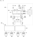
- FIG 1 is a hydraulic circuit diagram illustrating an electronic brake system according to an embodiment.
- the electronic brake system may include a master cylinder 120 that pressurizes and discharges a pressurized medium accommodated therein by an operation of a brake pedal 100, a reservoir 130 which is connected to a upper side of the master cylinder 120 and stores the pressurized medium, wheel cylinders 140 provided in respective wheels RR, RL, FR and FL, a hydraulic pressure supply device 200 operated by an electrical signal corresponding to a displacement of the brake pedal 100 to generate a hydraulic pressure and supply the generated hydraulic pressure to each of the wheel cylinders 140 provided in the respective wheels RR, RL, FR and FL, and a hydraulic control unit 300 that controls a flow of the hydraulic pressure transferred to each of the wheel cylinders 140 by the hydraulic pressure supply device 200.
- a master cylinder 120 that pressurizes and discharges a pressurized medium accommodated therein by an operation of a brake pedal 100
- a reservoir 130 which is connected to a upper side of the master cylinder 120 and stores the pressurized medium
- wheel cylinders 140 provided in respective wheels
- the hydraulic pressure supply device 200 may be provided to receive an electrical signal corresponding to a driver's braking intention from a pedal displacement sensor (PTS) detecting a displacement of the brake pedal 100 and generate a hydraulic pressure of the pressurized medium through a mechanical operation.
- PTS pedal displacement sensor
- the hydraulic pressure supply device 200 may include a hydraulic pressure providing unit 210 that provides a pressure of the pressurized medium transferred to each of the wheel cylinders 140, a motor-driven actuator 220 that operates the hydraulic pressure providing unit 210 using a motor 221, and a plurality of control valves 230 that control the flow of the hydraulic pressure.
- the hydraulic pressure providing unit 210 may include a cylinder block 211 provided to accommodate the pressurized medium, a hydraulic piston 214 accommodated in the cylinder block 211, and a drive shaft 215 that transfers power output from the motor-driven actuator 220 to the hydraulic piston 214.
- the cylinder block 211 may include a first pressure chamber 212 positioned in front of the hydraulic piston 214 and a second pressure chamber 213 positioned at a rear of the hydraulic piston 214.
- the plurality of control valves 230 may include first to fourth control valves 231, 232, 233 and 234.
- the first to third control valves 231, 232 and 233 may control a flow of the pressurized medium transferred to the hydraulic control unit 300 from the first pressure chamber 212 and/or the second pressure chamber 213 or a flow of the pressurized medium between the first pressure chamber 212 and the second pressure chamber 213, by a formation of flow paths depending on an opening and closing of valves.
- the first to third control valves 231, 232 and 233 may be provided as a normally closed type solenoid valve that operates to be open when an on-driving signal is received from a controller 400 in a normally closed state.
- the first current sensor 500 may detect current supplied from the first inverter 600 to stator windings (221a : U1, V1 and W1) of a first system of the motor 221.
- the processor 410 may control overall operations of the electronic brake system.
- the processor 410 may control operations of the first inverter 600 and/or the second inverter 610.
- the processor 410 may control operations of each electronic valve by outputting a valve command signal to each of the electronic valves of the electronic brake system including the control valves 231, 232, 233 and 234.
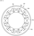
- FIG 3 illustrates a configuration of a motor of an electronic brake system according to an embodiment.
- the motor 221 may include a stator 700 disposed outside and a rotor 701 disposed inside.
- a yoke portion 705 and a plurality of teeth 706 protruding inward from the yoke portion 705 may be formed.
- twelve teeth 706 may be provided in the motor 221.
- a slot 707 may be formed between each of the teeth 706.
- the motor 221 may have twelve slots 707.
- the stator winding 704 wound around the tooth 706 may be accommodated in the slot 707.
- the rotor core 709 may be disposed around the rotation shaft 708.
- the magnet 710 is fixed around an outer circumference of the rotor core 709.
- Fourteen magnets 710 are disposed along the outer circumference of the rotor core 709.
- the motor 221 may be a motor having fourteen poles and twelve slots.
- the motor 221 may be driven by two independent energized systems.
- the stator windings 704 of the first system may be connected in a Y configuration.
- the stator windings 704 of the second system may also be connected in a Y configuration.
- stator windings U1a(+), W1b(-), V1b(+), U1b(-), W1a(+), V1a(-)) of the first system fail, and the stator windings (W2b(+), V2b(-), U2b(+), W2a(-), V2a(+), U2a(-)) of the second system are normal.
- the processor 410 may operate the motor 221 by supplying current to the stator windings (W2b(+), V2b(-), U2b(+), W2a(-), V2a(+), U2a(-)) of the second system through the second inverter 610.
- the current may be supplied to only the stator windings (W2b(+), V2b(-), U2b(+), W2a(-), V2a(+), U2a(-)) of the second system which is normal, without supplying the current to the stator windings (U1a(+), W1b(-), V1b(+), U1b(-), W1a(+), V1a(-)) of the first system which is malfunctioning. Accordingly, the rotor 701 of the motor 221 may be rotated only by the stator windings (W2b(+), V2b(-), U2b(+), W2a(-), V2a(+), U2a(-)) of the second system.
- stator windings (U1a(+), W1b(-), V1b(+), U1b(-), W1a(+), V1a(-)) of the first system are normal, and the stator windings (W2b(+), V2b(-), U2b(+), W2a(-), V2a(+), U2a(-)) of the second system fail.
- the processor 410 may operate the motor 221 by supplying current to the stator windings (U1a(+), W1b(-), V1b(+), U1b(-), W1a(+), V1a(-)) of the first system through the first inverter 600.
- the current may be supplied to only the stator windings (U1a(+), W1b(-), V1b(+), U1b(-), W1a(+), V1a(-)) of the first system which is normal, without supplying the current to the stator windings (W2b(+), V2b(-), U2b(+), W2a(-), V2a(+), U2a(-)) of the second system which is malfunctioning. Accordingly, the rotor 701 of the motor 221 may be rotated only by the stator windings (U1a(+), W1b(-), V1b(+), U1b(-), W1a(+), V1a(-)) of the first system.
- the motor includes two independent systems
- the first system and the second system cooperate to rotate the rotor in a normal state
- the rotor may be rotated only the stator windings of the other system. Accordingly, even when one of the systems fails, the other system may continue to function, and thus the motor may be continuously driven by reducing a motor performance without stopping the motor.
- the motor performance may be reduced in half because the motor is required to be driven using only the normal system.
- more current is required to be supplied to the stator windings of normal system, causing an excessive motor heat.
- a larger size motor has been designed considering a failure of one system to prevent the above, but a large motor may lead to a difficulty in packaging and integration with an existing motor.
- the electronic brake system may drive the motor 221 by using only the normal system, and increase a hydraulic pressure discharged from the first pressure chamber 212 or the second pressure chamber 213 by communicating the first pressure chamber 212 and the second pressure chamber 213. Accordingly, a deterioration of the motor performance due to a failure of one of the systems of the motor may be compensated for by increasing the hydraulic pressure discharged from the pressure chamber, and thereby may stably secure a braking performance of system.
- the first pressure chamber 212 and the second pressure chamber 213 may communicate with each other by opening control valves provided on a flow path connecting the first pressure chamber 212 and the second pressure chamber 213.
- the hydraulic pressure discharged from the first pressure chamber 212 may be increased. Also, by transferring a portion of the hydraulic pressure discharged from the second pressure chamber 213 to the first pressure chamber 212 to be used to push the hydraulic piston 214, the hydraulic pressure discharged from the second pressure chamber 213 may be increased.
- FIG 6 illustrates a state where an electronic brake system according to an embodiment performs a normal braking mode.
- the controller 400 may operate the hydraulic pressure supply device 200 depending on a displacement of the brake pedal 100.
- the controller 400 may open the first control valve 231 and the second control valve 232, and drive the motor 221 by supplying current to stator windings (U1a(+), W1b(-), V1b(+), U1b(-), W1a(+), V1a(-)) of the first system through the first inverter 600 and supplying current to the stator windings (W2b(+), V2b(-), U2b(+), W2a(-), V2a(+), U2a(-)) of the second system through the second inverter 610.
- the controller 400 may perform a normal braking mode that opens the first control valve 231 and the second control valve 232 and drives the motor 221.
- the third control valve 233 may be in a closed state in the normal braking mode. That is, the first pressure chamber 212 and the second pressure chamber 213 may not communicate with each other in the normal braking mode.
- the hydraulic piston 214 is moved by an operation of the motor 221, generating a hydraulic pressure in the first pressure chamber 212.
- the hydraulic pressure discharged from the first pressure chamber 212 may be transferred to the first hydraulic circuit 310 and the second hydraulic circuit 320 of the hydraulic control unit 300 through the first control valve 231 and the second control valve 232 which are switched to the open state.
- the hydraulic pressure transferred to the first hydraulic circuit 310 and the second hydraulic circuit 320 may be transferred to each of the wheel cylinders 140 through inlet valves, generating a braking force to each vehicle wheel.
- FIG 7 illustrates a state where an electronic brake system according to an embodiment performs a safe braking mode.
- the controller 400 may switch the normal braking mode to a safe braking mode to additionally open the third control valve 233, thereby communicating the first pressure chamber 212 and the second pressure chamber 213.
- the fourth control valve 234 may be in a closed state. Accordingly, by transferring a portion of the hydraulic pressure discharged from the first pressure chamber 212 to the second pressure chamber 213 to be used to push the hydraulic piston 214, the hydraulic pressure discharged from the first pressure chamber 212 may be increased.
- a motor performance may be reduced in half because the motor is required to be driven using only the normal system. Accordingly, the hydraulic pressure discharged from the first pressure chamber 212 may be decreased. However, by switching the normal braking mode to the safe braking mode and communicating the first pressure chamber 212 and the second pressure chamber 213, the portion of the hydraulic pressure discharged from the first pressure chamber 212 may be transferred to the second pressure chamber 213 to be used to push the hydraulic piston 214, thereby increasing the hydraulic pressure discharged from the first pressure chamber 212.
- a deterioration of the motor performance due to a failure of one of the systems of the motor may be compensated for by increasing the hydraulic pressure discharged from the pressure chamber, and thus a similar braking performance as before the motor failure may be stably secured, without supplying more current to stator windings of the normal system.
- FIG 8 illustrates a control method of an electronic brake system according to an embodiment.
- the controller 400 may detect current of the stator windings (U1, V1 and W1) of the first system detected through the first current sensor 500 (800), and also detect current of the stator windings (U2, V2 and W2) of the second system detected through the second current sensor 510 (802).
- the controller 400 may determine whether the first system or the second system fails based on information about the detected current (804).
- the controller 400 may maintain a normal braking mode as a braking mode (806).
- a normal braking mode the first control valve 231 and the second control valve 232 are open, the motor 221 is driven, and the third control valve 233 may be in a closed state in order not to communicate the first pressure chamber 212 and the second pressure chamber 213.
- the controller 400 may switch the normal braking mode to a safe braking mode (808).
- the third control valve 233 is additionally open in addition to the normal braking mode, and thus the first pressure chamber 212 and the second pressure chamber 213 communicate with each other.
- the fourth control valve 234 may be in a closed state.
- a portion of a hydraulic pressure discharged from the first pressure chamber 212 may be transferred to the second pressure chamber 213 to be used to push the hydraulic piston 214, thereby increasing the hydraulic pressure discharged from the first pressure chamber 212. Accordingly, a deterioration of the motor performance due to a failure of one of the systems of the motor may be compensated for by increasing the hydraulic pressure discharged from the pressure chamber, and thus a similar braking performance as before the motor failure may be stably secured, without supplying more current to stator windings of the normal system.
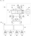
- FIG 9 is a hydraulic circuit diagram illustrating an electronic brake system according to another embodiment.
- the hydraulic pressure supply device 200 may include a plurality of control valves 230.
- the plurality of control valves 230 may include first to third control valves 235, 236 and 234.
- the first and second control valves 235 and 236 may control a flow of a pressurized medium transferred to the hydraulic control unit 300 from the first pressure chamber 212 and/or the second pressure chamber 213 or a flow of the pressurized medium between the first pressure chamber 212 and the second pressure chamber 213, by a formation of flow paths depending on an opening and closing of valves.
- the first and second control valves 235 and 236 may be provided as a normally closed type solenoid valve that operates to be open when an on-driving signal is received from the controller 400 in a normally closed state.
- the third control valve 234 may control a flow of the pressurized medium between the second pressure chamber 213 and the reservoir 130.
- the third control valve 234 may be provided as a normally open type solenoid valve that operates to be closed when an on-driving signal is received from the controller 400 in a normally open state.
- Types and the number of the plurality of control valves 230 may vary depending on a structure of flow paths.
- FIG 10 illustrates a state where an electronic brake system according to another embodiment performs a normal braking mode.
- the controller 400 may operate the hydraulic pressure supply device 200 depending on a displacement of the brake pedal 100.
- the controller 400 may open the first control valve 235 and close the second control valve 236. Also, the controller 400 may drive the motor 221 by supplying current to stator windings (U1a(+), W1b(-), V1b(+), U1b(-), W1a(+), V1a(-)) of a first system through the first inverter 600 and supplying current to the stator windings (W2b(+), V2b(-), U2b(+), W2a(-), V2a(+), U2a(-)) of a second system through the second inverter 610.
- stator windings U1a(+), W1b(-), V1b(+), U1b(-), W1a(+), V1a(-)
- the controller 400 may perform a normal braking mode that drives the motor 221 and closes one of the first control valve 235 and the second control valve 236 (for example, opens the first control valve 235 and closes the second control valve 236).
- the third control valve 233 may be in a closed state in the normal braking mode. That is, the first pressure chamber 212 and the second pressure chamber 213 may not communicate with each other in the normal braking mode.
- the hydraulic piston 214 is moved by an operation of the motor 221, generating a hydraulic pressure in the first pressure chamber 212.
- the hydraulic pressure discharged from the first pressure chamber 212 may be transferred to the first hydraulic circuit 310 and the second hydraulic circuit 320 of the hydraulic control unit 300 by flowing in a direction of an arrow.
- the hydraulic pressure transferred to the first hydraulic circuit 310 and the second hydraulic circuit 320 may be transferred to each of the wheel cylinders 140 through inlet valves, generating a braking force to each vehicle wheel.
- FIG 11 illustrates a state where an electronic brake system according to another embodiment performs a safe braking mode.
- the controller 400 may switch the normal braking mode to a safe braking mode that opens both the first control valve 235 and the second control valve 236, thereby communicating the first pressure chamber 212 and the second pressure chamber 213. Accordingly, by transferring a portion of a hydraulic pressure discharged from the first pressure chamber 212 to the second pressure chamber 213 to be used to push the hydraulic piston 214, the hydraulic pressure discharged from the first pressure chamber 212 may be increased.
- a motor performance may be reduced in half because the motor is required to be driven using only the normal system. Accordingly, the hydraulic pressure discharged from the first pressure chamber 212 may be decreased. However, by switching the normal braking mode to the safe braking mode and communicating the first pressure chamber 212 and the second pressure chamber 213, the portion of the hydraulic pressure discharged from the first pressure chamber 212 may be transferred to the second pressure chamber 213 to be used to push the hydraulic piston 214, thereby increasing the hydraulic pressure discharged from the first pressure chamber 212.
- a deterioration of the motor performance due to a failure of one of the systems of the motor may be compensated for by increasing the hydraulic pressure discharged from the pressure chamber, and thus a similar braking performance as before the motor failure may be stably secured, without supplying more current to stator windings of the normal system.
Landscapes
- Engineering & Computer Science (AREA)
- Transportation (AREA)
- Mechanical Engineering (AREA)
- Physics & Mathematics (AREA)
- Fluid Mechanics (AREA)
- Valves And Accessory Devices For Braking Systems (AREA)
- Regulating Braking Force (AREA)
Description
- The invention relates to an electronic brake system and a control method thereof, and more particularly, to an electronic brake system and a control method thereof that generate a braking force according to an electrical signal corresponding to a displacement of a brake pedal.
- In general, an electronic brake system may include a hydraulic pressure supply device. Once a driver operates a brake pedal, the hydraulic pressure supply device of the electronic brake system receives an electrical signal indicating the driver's braking intention from a pedal displacement sensor that detects a displacement of the brake pedal, such that the hydraulic pressure is supplied to wheel cylinders.
- The electronic brake system provided with the above-described hydraulic pressure supply device has been disclosed in European Registered Patent No.
EP 2520473 . According to this European Patent document, the hydraulic pressure supply device may generate a hydraulic pressure required for braking and supply the hydraulic pressure to wheel cylinders by operating a motor based on a pedal effort of a brake pedal and changing a position of a piston due to a rotational force of the motor. - An electric motor apparatus disclosed in
Japanese Registered Patent No. 3875188 - For example
KR 2019 0124460 A -
KR 2018 0126258 A -
KR 102 021 907 B1 -
US 10 077 036 B2 US 2012/0326492 A1 relates to a brake device for motor vehicles which has a master brake cylinder for generating brake pressure at at least one wheel brake. To be able to vary the brake pressure at particular wheel brakes individually, a pressure modulation cylinder having a plurality of chambers is provided between the master brake cylinder and the wheel brakes, a first chamber being connected via a first fluid line to the master brake cylinder, and a second chamber being connected via a second fluid line to the at least one wheel brake. - An electronic brake system requires high safety, since it greatly affects a safety of vehicle. Accordingly, a separate winding motor has been recently employed in an electronic brake system.
- In the electronic brake system using the separate winding motor, when an error occurs in one system of a motor, only half of the motor performance is capable of being used. However, because a vehicle driven by the motor is not changed, more current is used to achieve a similar level of performance, causing a risk of excessive motor heat, and the like.
- To prevent the above, a larger size motor is required to be designed considering a failure of one of the systems. However, a large motor may lead to a difficulty in packaging and integration with an existing motor.
- An aspect of the invention provides an electronic brake system and a control method thereof that may miniaturize a motor as well as stably secure a braking performance even when a motor performance is reduced.
- According to a first aspect of the present invention, there is provided an electronic brake system including: a motor comprising a first winding and a second winding; a piston coupled to the motor through a power transmission member; a cylinder configured to accommodate the piston, and comprising a first chamber and a second chamber partitioned by the piston; a flow path coupled to the first chamber and the second chamber; a control valve provided on the flow path; a first inverter configured to supply a current to the first winding; a second inverter configured to supply a current to the second winding; and a processor configured to control the first inverter, the second inverter and the control valve, based on an output of a pedal displacement sensor, wherein the processor is configured to open the control valve based on identifying a failure of at least one of the first winding, the second winding, the first inverter or the second inverter and wherein, when the failure of the at least one of the first winding, the second winding, the first inverter or the second inverter is not identified, the processor is configured to close the control valve.
- Preferably, a first current sensor is configured to detect a current supplied to the first winding; and a second current sensor configured to detect a current supplied to the second winding.
- In a preferred embodiment of the present invention, the processor is configured to identify the failure of the at least one of the first winding, the second winding, the first inverter or the second inverter based on an output of the first current sensor and an output of the second current sensor.
- In another preferred embodiment of the present invention, the processor is also configured to: control the second inverter to drive the motor based on identifying the failure of at least one of the first winding or the first inverter, and control the first inverter to drive the motor based on identifying the failure of at least one of the second winding or the second inverter.
- In a still another preferred embodiment of the present invention, the processor is configured to control the motor so that at least a portion of a hydraulic pressure of the first chamber is provided to the second chamber while the control valve is open.
- According to another aspect of the present invention, there is provided an electronic brake system further comprising a first hydraulic circuit is configured to control a hydraulic pressure transferred from the first chamber to a first wheel cylinder; and a second hydraulic circuit configured to control a hydraulic pressure transferred from the first chamber to a second wheel cylinder.
- In a preferred embodiment of the present invention, the motor further comprises a stator and a rotor, and the first winding and the second winding is alternately arranged on the stator.
- According to still another aspect of the present invention, there is provided a control method of an electronic brake system comprising a motor comprising a first winding and a second winding, a piston configured to be connected to the motor through a power transmission member, a cylinder configured to accommodate the piston and comprising a first chamber and a second chamber partitioned by the piston, a flow path configured to connect the first chamber and the second chamber, a control valve provided on the flow path, a first inverter configured to supply a current to the first winding; and a second inverter configured to supply a current to the second winding, the control method comprising: controlling the first inverter, the second inverter and the control valve based on an output of a pedal displacement sensor; identifying whether at least one of the first winding, the second winding, the first inverter or the second inverter fails; and opening the control valve based on identifying a failure of the at least one of the first winding, the second winding, the first inverter or the second inverter wherein when the failure of the at least one of the first winding, the second winding, the first inverter or the second inverter is not identified, closing the control valve.
- In another embodiment of the present invention the electronic brake system includes: a reservoir in which a pressurized medium is stored; a hydraulic pressure supply device including a first pressure chamber provided in front of a hydraulic piston and a second pressure chamber provided at a rear of the hydraulic piston, and configured to generate a hydraulic pressure by moving the hydraulic piston forward or backward; a hydraulic control unit configured to control a flow of the hydraulic pressure transferred to a wheel cylinder from the hydraulic pressure supply device; and a controller configured to control the hydraulic pressure supply device and the hydraulic control unit, wherein the hydraulic pressure supply device includes a motor having a plurality of separate system windings for moving the hydraulic piston, and a control valve configured to open and close a flow path that communicates the first pressure chamber and the second pressure chamber, and when a portion of the plurality of separate system windings of the motor fails, the controller is configured to open the control valve to push the hydraulic piston so that a portion of a hydraulic pressure discharged from a pressure chamber is transferred to another pressure chamber.
- According to one embodiment of the present invention the motor includes a first system stator winding driven by a first inverter and a second system stator winding driven by a second inverter.
- According to another embodiment of the present invention the electronic brake system includes: a first current sensor configured to detect a current supplied to the first system stator winding from the first inverter, and a second current sensor configured to detect a current supplied to the second system stator winding from the second inverter.
- According to one embodiment of the present invention the controller is configured to determine a failure of the first system stator winding based on a first system stator winding current detected by the first current sensor, and a failure of the second system stator winding based on a second system stator winding current detected by the second current sensor.
- According to another embodiment of the present invention the controller is configured to cut off a current input to a malfunctioning system stator winding.
- According to another embodiment of the present invention the electronic brake system includes: a reservoir in which a pressurized medium is stored; a hydraulic pressure supply device including a first pressure chamber provided in front of a hydraulic piston and a second pressure chamber provided at a rear of the hydraulic piston, and configured to generate a hydraulic pressure by moving the hydraulic piston forward or backward; a hydraulic control unit configured to control a flow of the hydraulic pressure transferred to a wheel cylinder from the hydraulic pressure supply device; and a controller configured to control the hydraulic pressure supply device and the hydraulic control unit, wherein the hydraulic pressure supply device includes a motor having a first system stator winding driven by a first inverter and a second system stator winding driven by a second inverter, and a control valve configured to open and close a flow path that communicates the first pressure chamber and the second pressure chamber, and when the first system stator winding or the second system stator winding fails during a normal braking mode, the controller is configured to switch to a safe braking mode for opening the control valve to push the hydraulic piston, so that a portion of a hydraulic pressure discharged from a pressure chamber is transferred to another pressure chamber.
- According to still another embodiment of the present invention, the control method of an electronic brake system includes a reservoir in which a pressurized medium is stored, a hydraulic pressure supply device including a first pressure chamber provided in front of a hydraulic piston and a second pressure chamber provided at a rear of the hydraulic piston and configured to generate a hydraulic pressure by moving the hydraulic piston forward or backward, a hydraulic control unit configured to control a flow of the hydraulic pressure transferred to a wheel cylinder from the hydraulic pressure supply device, and a controller configured to control the hydraulic pressure supply device and the hydraulic control unit, wherein the hydraulic pressure supply device includes a motor having a plurality of separate system windings for moving the hydraulic piston and a control valve configured to open and close a flow path that communicates the first pressure chamber and the second pressure chamber, the control method including: determining whether a portion of the plurality of system windings of the motor fails, and when the portion of the plurality of system windings fails, opening the control valve to push the hydraulic piston, so that a portion of a hydraulic pressure discharged from a pressure chamber is transferred to another pressure chamber.
- According to an aspect of the invention, an electronic brake system and a control method thereof can miniaturize a motor as well as stably secure a braking performance even when a motor performance is reduced due to a partial failure of the motor.
-
-
FIG 1 is a hydraulic circuit diagram illustrating an electronic brake system according to an embodiment. -
FIG 2 is a control block diagram illustrating an electronic brake system according to an embodiment. -
FIG 3 illustrates a configuration of a motor of an electronic brake system according to an embodiment. -
FIG 4 illustrates a failure of a first system of a motor of an electronic brake system according to an embodiment. -
FIG 5 illustrates a failure of a second system of a motor of an electronic brake system according to an embodiment. -
FIG 6 illustrates a state where an electronic brake system according to an embodiment performs a normal braking mode. -
FIG 7 illustrates a state where an electronic brake system according to an embodiment performs a safe braking mode. -
FIG 8 illustrates a control method of an electronic brake system according to an embodiment. -
FIG 9 is a hydraulic circuit diagram illustrating an electronic brake system according to another embodiment. -
FIG 10 illustrates a state where an electronic brake system according to another embodiment performs a normal braking mode. -
FIG 11 illustrates a state where an electronic brake system according to another embodiment performs a safe braking mode. - Like reference numerals throughout the specification denote like elements. Also, this specification does not describe all the elements according to embodiments of the invention, and descriptions well-known in the art to which the invention pertains or overlapped portions are omitted. The terms such as "~part", "~member", "~module", "~block", and the like may refer to at least one process processed by at least one hardware or software. According to embodiments, a plurality of "~part", "~member", "~module", "~block" may be embodied as a single element, or a single of "~part", "~member", "~module", "~block" may include a plurality of elements.
- It will be understood that when an element is referred to as being "connected" to another element, it can be directly or indirectly connected to the other element, wherein the indirect connection includes connection via a wireless communication network.
- It will be understood that the term "include" when used in this specification, specifies the presence of stated elements, but do not preclude the presence or addition of one or more other elements.
- It will be understood that when it is stated in this specification that a member is located "on" another member, not only a member may be in contact with another member, but also still another member may be present between the two members.
- It will be understood that, although the terms first, second, etc. may be used herein to describe various elements, these elements should not be limited by these terms. It is to be understood that the singular forms are intended to include the plural forms as well, unless the context clearly dictates otherwise.
- Reference numerals used for method steps are just used for convenience of explanation, but not to limit an order of the steps. Thus, unless the context clearly dictates otherwise, the written order may be practiced otherwise.
-
FIG 1 is a hydraulic circuit diagram illustrating an electronic brake system according to an embodiment. - Referring to
FIG 1 , the electronic brake system may include amaster cylinder 120 that pressurizes and discharges a pressurized medium accommodated therein by an operation of abrake pedal 100, areservoir 130 which is connected to a upper side of themaster cylinder 120 and stores the pressurized medium, wheel cylinders 140 provided in respective wheels RR, RL, FR and FL, a hydraulicpressure supply device 200 operated by an electrical signal corresponding to a displacement of thebrake pedal 100 to generate a hydraulic pressure and supply the generated hydraulic pressure to each of the wheel cylinders 140 provided in the respective wheels RR, RL, FR and FL, and ahydraulic control unit 300 that controls a flow of the hydraulic pressure transferred to each of the wheel cylinders 140 by the hydraulicpressure supply device 200. - The hydraulic
pressure supply device 200 may be provided to receive an electrical signal corresponding to a driver's braking intention from a pedal displacement sensor (PTS) detecting a displacement of thebrake pedal 100 and generate a hydraulic pressure of the pressurized medium through a mechanical operation. - The hydraulic
pressure supply device 200 may include a hydraulicpressure providing unit 210 that provides a pressure of the pressurized medium transferred to each of the wheel cylinders 140, a motor-drivenactuator 220 that operates the hydraulicpressure providing unit 210 using amotor 221, and a plurality ofcontrol valves 230 that control the flow of the hydraulic pressure. - The hydraulic
pressure providing unit 210 may include acylinder block 211 provided to accommodate the pressurized medium, ahydraulic piston 214 accommodated in thecylinder block 211, and adrive shaft 215 that transfers power output from the motor-drivenactuator 220 to thehydraulic piston 214. Thecylinder block 211 may include afirst pressure chamber 212 positioned in front of thehydraulic piston 214 and asecond pressure chamber 213 positioned at a rear of thehydraulic piston 214. - The plurality of
control valves 230 may include first tofourth control valves - The first to
third control valves hydraulic control unit 300 from thefirst pressure chamber 212 and/or thesecond pressure chamber 213 or a flow of the pressurized medium between thefirst pressure chamber 212 and thesecond pressure chamber 213, by a formation of flow paths depending on an opening and closing of valves. For example, the first tothird control valves controller 400 in a normally closed state. - The
fourth control valve 234 may control a flow of the pressurized medium between thesecond pressure chamber 213 and thereservoir 130. For example, thefourth control valve 234 may be provided as a normally open type solenoid valve that operates to be closed when an on-driving signal is received from thecontroller 400 in a normally open state. - Types and the number of the plurality of
control valves 230 may vary depending on a structure of flow paths. - The hydraulic
pressure supply device 200 may include a motor pump or a high pressure accumulator instead of the hydraulicpressure providing unit 210 and the motor-drivenactuator 220. - The
hydraulic control unit 300 may include a firsthydraulic circuit 310 that controls the flow of the pressurized medium transferred to first andsecond wheel cylinders hydraulic circuit 320 that controls the flow of the pressurized medium transferred to third andfourth wheel cylinders - For example, the first
hydraulic circuit 310 may control a braking force of the front right wheel FR and the rear left wheel RL. The secondhydraulic circuit 320 may control a braking force of the rear right wheel RR and the front left wheel FL. - The
hydraulic control unit 300 may include an inlet valve provided at a front end of each of thewheel cylinders wheel cylinders reservoir 130. The hydraulicpressure supply device 200 and a front end of the inlet valve of the firsthydraulic circuit 310 may be connected to each other, and the hydraulicpressure supply device 200 and a front end of the inlet valve of the secondhydraulic circuit 320 may be connected to each other. The hydraulic pressure generated and provided from the hydraulicpressure supply device 200 may be supplied to each of the firsthydraulic circuit 310 and the secondhydraulic circuit 320. -
FIG 2 is a control block diagram illustrating an electronic brake system according to an embodiment. - Referring to
FIG 2 , the electronic brake system may include thecontroller 400 that performs an overall control. - The
controller 400 is electrically connected to a pedal displacement sensor (PTS), a firstcurrent sensor 500, a secondcurrent sensor 510, afirst inverter 600, asecond inverter 610 and thecontrol valves - The pedal displacement sensor (PTS) may detect an operation and a displacement of the
brake pedal 100. - The first
current sensor 500 may detect current supplied from thefirst inverter 600 to stator windings (221a : U1, V1 and W1) of a first system of themotor 221. - The second
current sensor 510 may detect current supplied from thesecond inverter 610 to stator windings (221b : U2, V2 and W2) of a second system of themotor 221. - The
first inverter 600 may supply current to the stator windings (U1, V1 and W1) of the first system of themotor 221. - The
second inverter 610 may supply current to the stator windings (U2, V2 and W2) of the second system of themotor 221. - The
first inverter 600 and thesecond inverter 610 may drive themotor 221 by converting a DC voltage provided from a battery of a vehicle into a three-phase AC voltage in a form of a pulse having an arbitrary variable frequency through pulse width modulation (PWM). Thefirst inverter 600 and thesecond inverter 610 may include a plurality of power switching elements and a plurality of diodes. For example, each of thefirst inverter 600 and thesecond inverter 610 may include six power switching elements Q1 to Q6 and six diodes D1 to D6. The six power switching elements Q1 to Q6 may be paired in series and connected to the stator windings (U1, V1 and W1) of the first system of themotor 221 or the stator windings (U2, V2 and W2) of the second system of themotor 221, respectively. Thefirst inverter 600 and thesecond inverter 610 may convert the current, provided from the battery, to AC from DC by turning on or off each of the power switching elements according to a control signal of thecontroller 400, thereby supplying the current to the stator windings (U1, V1 and W1) of the first system of themotor 221 and/or the stator windings (U2, V2 and W2) of the second system of themotor 221. - The
controller 400 may perform an overall control of the electronic brake system. - The
controller 400 may control the hydraulicpressure supply device 200 and thehydraulic control unit 300. - The
controller 400 may be referred to as an electronic control unit (ECU). - The
controller 400 may include aprocessor 410 and amemory 420. - The
memory 420 may store a program for processing or controlling theprocessor 410 and various data for operating the electronic brake system. - The
memory 420 may include a volatile memory such as a static random access memory (S-RAM) and dynamic random access memory (D-RAM), and a non-volatile memory such as a flash memory, a read only memory (ROM), an erasable programmable read only memory (EPROM), and the like. - The
processor 410 may control overall operations of the electronic brake system. - The
processor 410 may receive brake pedal displacement information through the pedal displacement sensor (PTS). - The
processor 410 may receive current information of the stator windings (U1, V1 and W1) of the first system detected through the firstcurrent sensor 500. - The
processor 410 may receive current information of the stator windings (U2, V2 and W2) of the second system detected through the secondcurrent sensor 510. - The
processor 410 may diagnose the current information of the stator windings (U1, V1 and W1) of the first system, detected through the firstcurrent sensor 500, and thereby may determine whether a temporary failure or permanent failure such as disconnection or short circuit occurs in the stator windings (U1, V1 and W1) of the first system. Theprocessor 410 may determine a failure of thefirst inverter 600. - The
processor 410 may diagnose the current information of the stator windings (U2, V2 and W2) of the second system, detected through the secondcurrent sensor 510, and thereby may determine whether a temporary failure or permanent failure such as disconnection or short circuit occurs in the stator windings (U2, V2 and W2) of the second system. Theprocessor 410 may determine a failure of thesecond inverter 610. - The
processor 410 may control operations of thefirst inverter 600 and/or thesecond inverter 610. - The
processor 410 may operate themotor 221 by outputting a motor command signal to thefirst inverter 600 to supply the current to the stator windings (U1, V1 and W1) of the first system of themotor 221. - The
processor 410 may operate themotor 221 by outputting a motor command signal to thesecond inverter 610 to supply the current to the stator windings (U2, V2 and W2) of the second system of themotor 221. The motor command signal may include a target pressure requested by a driver and a difference in requested target pressure between a previous driver and a current driver. - The
processor 410 may control operations of each electronic valve by outputting a valve command signal to each of the electronic valves of the electronic brake system including thecontrol valves -
FIG 3 illustrates a configuration of a motor of an electronic brake system according to an embodiment. - Referring to
FIG. 3 , themotor 221 may include astator 700 disposed outside and arotor 701 disposed inside. - The
stator 700 may include ahousing 702, astator core 703 fixed to an inner circumferential side of thehousing 702, and three-phase (U,V, W) stator windings (coil) 704 wound on thestator core 703. - In the
stator core 703, ayoke portion 705 and a plurality ofteeth 706 protruding inward from theyoke portion 705 may be formed. For example, twelveteeth 706 may be provided in themotor 221. Aslot 707 may be formed between each of theteeth 706. Themotor 221 may have twelveslots 707. The stator winding 704 wound around thetooth 706 may be accommodated in theslot 707. - The
rotor 701 may be positioned inside of thestator 700. Therotor 701 may include arotation shaft 708, arotor core 709 and amagnet 710. Therotation shaft 708, therotor core 709 and themagnet 710 may be disposed on a same axis. - The
rotor core 709 may be disposed around therotation shaft 708. Themagnet 710 is fixed around an outer circumference of therotor core 709. Fourteenmagnets 710 are disposed along the outer circumference of therotor core 709. Themotor 221 may be a motor having fourteen poles and twelve slots. - The
motor 221 may be driven by two independent energized systems. - The
stator windings 704 of themotor 221 are divided into two independent systems and wired. - The numbers 1 and 2 after U, V and W shown in
FIG 3 indicate a system (a first system or a second system) to which the stator winding 704 belongs. - The
stator windings 704 of the first system may be connected in a Y configuration. Thestator windings 704 of the second system may also be connected in a Y configuration. - The
stator windings 704 of the two systems may be alternately arranged in a circumferential direction. In phase windings of the same system may be arranged to face each other. The stator windings of the first system (first group three-phase coils) and the stator windings of the second system (second group three-phase coils) of thestator windings 704 may be alternately arranged in an order of U1a(+), W2b(+), W1b(-), V2b(-), V1b(+), U2b(+), U1b(-), W2a(-), W1a(+), V2a(+), V1a(-) and U2a(-). -
FIG 4 illustrates a failure of a first system of a motor of an electronic brake system according to an embodiment. - Referring to
FIG 4 , it is illustrated that, in themotor 221, the stator windings (U1a(+), W1b(-), V1b(+), U1b(-), W1a(+), V1a(-)) of the first system fail, and the stator windings (W2b(+), V2b(-), U2b(+), W2a(-), V2a(+), U2a(-)) of the second system are normal. - When the first system fails, the
processor 410 may operate themotor 221 by supplying current to the stator windings (W2b(+), V2b(-), U2b(+), W2a(-), V2a(+), U2a(-)) of the second system through thesecond inverter 610. That is, the current may be supplied to only the stator windings (W2b(+), V2b(-), U2b(+), W2a(-), V2a(+), U2a(-)) of the second system which is normal, without supplying the current to the stator windings (U1a(+), W1b(-), V1b(+), U1b(-), W1a(+), V1a(-)) of the first system which is malfunctioning. Accordingly, therotor 701 of themotor 221 may be rotated only by the stator windings (W2b(+), V2b(-), U2b(+), W2a(-), V2a(+), U2a(-)) of the second system. -
FIG 5 illustrates a failure of a second system of a motor of an electronic brake system according to an embodiment. - Referring to
FIG 5 , it is illustrated that, in themotor 221, the stator windings (U1a(+), W1b(-), V1b(+), U1b(-), W1a(+), V1a(-)) of the first system are normal, and the stator windings (W2b(+), V2b(-), U2b(+), W2a(-), V2a(+), U2a(-)) of the second system fail. - When the second system fails, the
processor 410 may operate themotor 221 by supplying current to the stator windings (U1a(+), W1b(-), V1b(+), U1b(-), W1a(+), V1a(-)) of the first system through thefirst inverter 600. That is, the current may be supplied to only the stator windings (U1a(+), W1b(-), V1b(+), U1b(-), W1a(+), V1a(-)) of the first system which is normal, without supplying the current to the stator windings (W2b(+), V2b(-), U2b(+), W2a(-), V2a(+), U2a(-)) of the second system which is malfunctioning. Accordingly, therotor 701 of themotor 221 may be rotated only by the stator windings (U1a(+), W1b(-), V1b(+), U1b(-), W1a(+), V1a(-)) of the first system. - As described above, because the motor includes two independent systems, the first system and the second system cooperate to rotate the rotor in a normal state, and when one of the two systems fails, the rotor may be rotated only the stator windings of the other system. Accordingly, even when one of the systems fails, the other system may continue to function, and thus the motor may be continuously driven by reducing a motor performance without stopping the motor.
- However, when one of the systems fails, the motor performance may be reduced in half because the motor is required to be driven using only the normal system. To achieve a similar level of performance as before the motor failure even in the above-described state, more current is required to be supplied to the stator windings of normal system, causing an excessive motor heat. Conventionally, a larger size motor has been designed considering a failure of one system to prevent the above, but a large motor may lead to a difficulty in packaging and integration with an existing motor.
- According to an embodiment, when one of the systems of the
motor 221 fails during braking control, the electronic brake system may drive themotor 221 by using only the normal system, and increase a hydraulic pressure discharged from thefirst pressure chamber 212 or thesecond pressure chamber 213 by communicating thefirst pressure chamber 212 and thesecond pressure chamber 213. Accordingly, a deterioration of the motor performance due to a failure of one of the systems of the motor may be compensated for by increasing the hydraulic pressure discharged from the pressure chamber, and thereby may stably secure a braking performance of system. Thefirst pressure chamber 212 and thesecond pressure chamber 213 may communicate with each other by opening control valves provided on a flow path connecting thefirst pressure chamber 212 and thesecond pressure chamber 213. By transferring a portion of the hydraulic pressure discharged from thefirst pressure chamber 212 to thesecond pressure chamber 213 to be used to push thehydraulic piston 214, the hydraulic pressure discharged from thefirst pressure chamber 212 may be increased. Also, by transferring a portion of the hydraulic pressure discharged from thesecond pressure chamber 213 to thefirst pressure chamber 212 to be used to push thehydraulic piston 214, the hydraulic pressure discharged from thesecond pressure chamber 213 may be increased. -
FIG 6 illustrates a state where an electronic brake system according to an embodiment performs a normal braking mode. - Once a driver operates the
brake pedal 100, thecontroller 400 may operate the hydraulicpressure supply device 200 depending on a displacement of thebrake pedal 100. - The
controller 400 may open thefirst control valve 231 and thesecond control valve 232, and drive themotor 221 by supplying current to stator windings (U1a(+), W1b(-), V1b(+), U1b(-), W1a(+), V1a(-)) of the first system through thefirst inverter 600 and supplying current to the stator windings (W2b(+), V2b(-), U2b(+), W2a(-), V2a(+), U2a(-)) of the second system through thesecond inverter 610. As such, thecontroller 400 may perform a normal braking mode that opens thefirst control valve 231 and thesecond control valve 232 and drives themotor 221. Thethird control valve 233 may be in a closed state in the normal braking mode. That is, thefirst pressure chamber 212 and thesecond pressure chamber 213 may not communicate with each other in the normal braking mode. - As the
controller 400 performs the normal braking mode, thehydraulic piston 214 is moved by an operation of themotor 221, generating a hydraulic pressure in thefirst pressure chamber 212. The hydraulic pressure discharged from thefirst pressure chamber 212 may be transferred to the firsthydraulic circuit 310 and the secondhydraulic circuit 320 of thehydraulic control unit 300 through thefirst control valve 231 and thesecond control valve 232 which are switched to the open state. The hydraulic pressure transferred to the firsthydraulic circuit 310 and the secondhydraulic circuit 320 may be transferred to each of the wheel cylinders 140 through inlet valves, generating a braking force to each vehicle wheel. -
FIG 7 illustrates a state where an electronic brake system according to an embodiment performs a safe braking mode. - Referring to
FIG 7 , when one of the first and second systems of themotor 221 fails during a normal braking mode, thecontroller 400 may switch the normal braking mode to a safe braking mode to additionally open thethird control valve 233, thereby communicating thefirst pressure chamber 212 and thesecond pressure chamber 213. In this instance, thefourth control valve 234 may be in a closed state. Accordingly, by transferring a portion of the hydraulic pressure discharged from thefirst pressure chamber 212 to thesecond pressure chamber 213 to be used to push thehydraulic piston 214, the hydraulic pressure discharged from thefirst pressure chamber 212 may be increased. - When one of the systems of the motor fails, a motor performance may be reduced in half because the motor is required to be driven using only the normal system. Accordingly, the hydraulic pressure discharged from the
first pressure chamber 212 may be decreased. However, by switching the normal braking mode to the safe braking mode and communicating thefirst pressure chamber 212 and thesecond pressure chamber 213, the portion of the hydraulic pressure discharged from thefirst pressure chamber 212 may be transferred to thesecond pressure chamber 213 to be used to push thehydraulic piston 214, thereby increasing the hydraulic pressure discharged from thefirst pressure chamber 212. Accordingly, a deterioration of the motor performance due to a failure of one of the systems of the motor may be compensated for by increasing the hydraulic pressure discharged from the pressure chamber, and thus a similar braking performance as before the motor failure may be stably secured, without supplying more current to stator windings of the normal system. -
FIG 8 illustrates a control method of an electronic brake system according to an embodiment. - Referring to
FIG 8 , during braking control, thecontroller 400 may detect current of the stator windings (U1, V1 and W1) of the first system detected through the first current sensor 500 (800), and also detect current of the stator windings (U2, V2 and W2) of the second system detected through the second current sensor 510 (802). - The
controller 400 may determine whether the first system or the second system fails based on information about the detected current (804). - When no failure of the first system or the second system is determined, the
controller 400 may maintain a normal braking mode as a braking mode (806). In the normal braking mode, thefirst control valve 231 and thesecond control valve 232 are open, themotor 221 is driven, and thethird control valve 233 may be in a closed state in order not to communicate thefirst pressure chamber 212 and thesecond pressure chamber 213. - On the other hand, when the first system or the second system fails, the
controller 400 may switch the normal braking mode to a safe braking mode (808). In the safe braking mode, thethird control valve 233 is additionally open in addition to the normal braking mode, and thus thefirst pressure chamber 212 and thesecond pressure chamber 213 communicate with each other. In this instance, thefourth control valve 234 may be in a closed state. - As such, when one of the systems of the motor fails, by switching the normal braking mode to the safe braking mode and communicating the
first pressure chamber 212 and thesecond pressure chamber 213, a portion of a hydraulic pressure discharged from thefirst pressure chamber 212 may be transferred to thesecond pressure chamber 213 to be used to push thehydraulic piston 214, thereby increasing the hydraulic pressure discharged from thefirst pressure chamber 212. Accordingly, a deterioration of the motor performance due to a failure of one of the systems of the motor may be compensated for by increasing the hydraulic pressure discharged from the pressure chamber, and thus a similar braking performance as before the motor failure may be stably secured, without supplying more current to stator windings of the normal system. -
FIG 9 is a hydraulic circuit diagram illustrating an electronic brake system according to another embodiment. - Referring to
FIG 9 , the hydraulicpressure supply device 200 may include a plurality ofcontrol valves 230. - The plurality of
control valves 230 may include first tothird control valves - The first and
second control valves hydraulic control unit 300 from thefirst pressure chamber 212 and/or thesecond pressure chamber 213 or a flow of the pressurized medium between thefirst pressure chamber 212 and thesecond pressure chamber 213, by a formation of flow paths depending on an opening and closing of valves. For example, the first andsecond control valves controller 400 in a normally closed state. - The
third control valve 234 may control a flow of the pressurized medium between thesecond pressure chamber 213 and thereservoir 130. For example, thethird control valve 234 may be provided as a normally open type solenoid valve that operates to be closed when an on-driving signal is received from thecontroller 400 in a normally open state. - Types and the number of the plurality of
control valves 230 may vary depending on a structure of flow paths. -
FIG 10 illustrates a state where an electronic brake system according to another embodiment performs a normal braking mode. - Once a driver operates the
brake pedal 100, thecontroller 400 may operate the hydraulicpressure supply device 200 depending on a displacement of thebrake pedal 100. - The
controller 400 may open thefirst control valve 235 and close thesecond control valve 236. Also, thecontroller 400 may drive themotor 221 by supplying current to stator windings (U1a(+), W1b(-), V1b(+), U1b(-), W1a(+), V1a(-)) of a first system through thefirst inverter 600 and supplying current to the stator windings (W2b(+), V2b(-), U2b(+), W2a(-), V2a(+), U2a(-)) of a second system through thesecond inverter 610. As such, thecontroller 400 may perform a normal braking mode that drives themotor 221 and closes one of thefirst control valve 235 and the second control valve 236 (for example, opens thefirst control valve 235 and closes the second control valve 236). Thethird control valve 233 may be in a closed state in the normal braking mode. That is, thefirst pressure chamber 212 and thesecond pressure chamber 213 may not communicate with each other in the normal braking mode. - As the
controller 400 performs the normal braking mode, thehydraulic piston 214 is moved by an operation of themotor 221, generating a hydraulic pressure in thefirst pressure chamber 212. The hydraulic pressure discharged from thefirst pressure chamber 212 may be transferred to the firsthydraulic circuit 310 and the secondhydraulic circuit 320 of thehydraulic control unit 300 by flowing in a direction of an arrow. The hydraulic pressure transferred to the firsthydraulic circuit 310 and the secondhydraulic circuit 320 may be transferred to each of the wheel cylinders 140 through inlet valves, generating a braking force to each vehicle wheel. -
FIG 11 illustrates a state where an electronic brake system according to another embodiment performs a safe braking mode. - Referring to
FIG 11 , when one of the first and second systems of themotor 221 fails during a normal braking mode, thecontroller 400 may switch the normal braking mode to a safe braking mode that opens both thefirst control valve 235 and thesecond control valve 236, thereby communicating thefirst pressure chamber 212 and thesecond pressure chamber 213. Accordingly, by transferring a portion of a hydraulic pressure discharged from thefirst pressure chamber 212 to thesecond pressure chamber 213 to be used to push thehydraulic piston 214, the hydraulic pressure discharged from thefirst pressure chamber 212 may be increased. - When one of the systems of the motor fails, a motor performance may be reduced in half because the motor is required to be driven using only the normal system. Accordingly, the hydraulic pressure discharged from the
first pressure chamber 212 may be decreased. However, by switching the normal braking mode to the safe braking mode and communicating thefirst pressure chamber 212 and thesecond pressure chamber 213, the portion of the hydraulic pressure discharged from thefirst pressure chamber 212 may be transferred to thesecond pressure chamber 213 to be used to push thehydraulic piston 214, thereby increasing the hydraulic pressure discharged from thefirst pressure chamber 212. Accordingly, a deterioration of the motor performance due to a failure of one of the systems of the motor may be compensated for by increasing the hydraulic pressure discharged from the pressure chamber, and thus a similar braking performance as before the motor failure may be stably secured, without supplying more current to stator windings of the normal system.
Claims (11)
- An electronic brake system, comprising:a motor (221);a piston (214) coupled to the motor through a power transmission member;a cylinder (120) configured to accommodate the piston (214), and comprising a first chamber (212) and a second chamber (213) partitioned by the piston (214);a flow path coupled to the first chamber (212) and the second chamber (213);a control valve (231, 232, 233) provided on the flow path;a pedal displacement sensor (PTS); anda processor (410),the electronic brake system being characterised in that:the motor (221) comprises a first winding (U1, V1 and W1) and a second winding (U2, V2 and W2);the electronic brake system further comprises:a first inverter (600) configured to supply a current to the first winding (U1, V1 and W1);a second inverter (610) configured to supply a current to the second winding (U2, V2 and W2); andthe processor (410) is configured to control the first inverter (600), the second inverter (610) and the control valve (231, 232, 233), based on an output of the pedal displacement sensor (PTS),wherein the processor (410) is configured to open the control valve (231, 232, 233) based on identifying a failure of at least one of the first winding (U1, V1 and W1), the second winding (U2, V2 and W2), the first inverter (600) or the second inverter (610) andwherein, when the failure of the at least one of the first winding (U1, V1 and W1), the second winding (U2, V2 and W2), the first inverter (600) or the second inverter (610) is not identified, the processor (410) is configured to close the control valve (231, 232, 233).
- The electronic brake system of claim 1, further comprising:a first current sensor (500) configured to detect a current supplied to the first winding (U1, V1 and W1); anda second current sensor (510) configured to detect a current supplied to the second winding (U2, V2 and W2).
- The electronic brake system of claim 2, wherein the processor (410) is configured to identify the failure of the at least one of the first winding (U1, V1 and W1), the second winding (U2, V2 and W2), the first inverter (600) or the second inverter (610) based on an output of the first current sensor (500) and an output of the second current sensor (510).
- The electronic brake system of claim 1, wherein the processor (410) is configured to:control the second inverter (610) to drive the motor based on identifying the failure of at least one of the first winding (U1, V1 and W1)or the first inverter (600), andcontrol the first inverter (600) to drive the motor based on identifying the failure of at least one of the second winding (U2, V2 and W2) or the second inverter (610).
- The electronic brake system of claim 1, wherein the processor (410) is configured to control the motor so that at least a portion of a hydraulic pressure of the first chamber (212) is provided to the second chamber (213) while the control valve (231, 232, 233) is open.
- The electronic brake system of claim 1, further comprising:a first hydraulic circuit (310) configured to control a hydraulic pressure transferred from the first chamber (212) to a first wheel cylinder (141); anda second hydraulic circuit (320) configured to control a hydraulic pressure transferred from the first chamber (212) to a second wheel cylinder (142).
- The electronic brake system of claim 1, wherein the motor further comprises a stator (700) and a rotor (701), and
the first winding (U1, V1 and W1) and the second winding (U2, V2 and W2) is alternately arranged on the stator (700). - A control method of an electronic brake system comprising a motor comprising a first winding (U1, V1 and W1) and a second winding (U2, V2 and W2), a piston (214) configured to be connected to the motor through a power transmission member, a cylinder (120) configured to accommodate the piston (214) and comprising a first chamber (212) and a second chamber (213) partitioned by the piston (214), a flow path configured to connect the first chamber (212) and the second chamber (213), a control valve (231, 232, 233) provided on the flow path, a first inverter (600) configured to supply a current to the first winding (U1, V1 and W1); and a second inverter (610) configured to supply a current to the second winding (U2, V2 and W2), the control method comprising:controlling the first inverter (600), the second inverter (610) and the control valve (231, 232, 233) based on an output of a pedal displacement sensor (PTS);identifying whether at least one of the first winding (U1, V1 and W1), the second winding (U2, V2 and W2), the first inverter (600) or the second inverter (610) fails; andopening the control valve (231, 232, 233) based on identifying a failure of the at least one of the first winding (U1, V1 and W1), the second winding (U2, V2 and W2), the first inverter (600) or the second inverter (610),wherein when the failure of the at least one of the first winding (U1, V1 and W1), the second winding (U2, V2 and W2), the first inverter (600) or the second inverter (610) is not identified, closing the control valve (231, 232, 233).
- The control method of claim 8, wherein the identifying of whether the at least one of the first winding (U1, V1 and W1), the second winding (U2, V2 and W2), the first inverter (600) or the second inverter (610) fails comprises identifying the failure of the at least one of the first winding (U1, V1 and W1), the second winding (U2, V2 and W2), the first inverter (600) or the second inverter (610) based on a current supplied to the first winding (U1, V1 and W1) and a current supplied to the second winding (U2, V2 and W2).
- The control method of claim 8, further comprising:controlling the second inverter (610) to drive the motor based on identifying the failure of at least one of the first winding (U1, V1 and W1) or the first inverter (600); andcontrolling the first inverter (600) to drive the motor based on identifying the failure of at least one of the second winding (U2, V2 and W2) or the second inverter (610).
- The control method of claim 8, further comprising:
controlling at least one of the first inverter (600) or the second inverter (610) so that at least a portion of a hydraulic pressure of the first chamber (212) is provided to the second chamber (213) while the control valve (231, 232, 233) is open.
Applications Claiming Priority (2)
| Application Number | Priority Date | Filing Date | Title |
|---|---|---|---|
| KR1020190176046A KR102804693B1 (en) | 2019-12-27 | 2019-12-27 | Electric brake system and control method thereof |
| PCT/KR2020/019130 WO2021133115A1 (en) | 2019-12-27 | 2020-12-24 | Electronic brake system and control method therefor |
Publications (3)
| Publication Number | Publication Date |
|---|---|
| EP4063210A1 EP4063210A1 (en) | 2022-09-28 |
| EP4063210A4 EP4063210A4 (en) | 2023-06-21 |
| EP4063210B1 true EP4063210B1 (en) | 2025-04-02 |
Family
ID=76576004
Family Applications (1)
| Application Number | Title | Priority Date | Filing Date |
|---|---|---|---|
| EP20905900.5A Active EP4063210B1 (en) | 2019-12-27 | 2020-12-24 | Electronic brake system and control method therefor |
Country Status (5)
| Country | Link |
|---|---|
| US (1) | US12291185B2 (en) |
| EP (1) | EP4063210B1 (en) |
| KR (1) | KR102804693B1 (en) |
| CN (1) | CN114901531B (en) |
| WO (1) | WO2021133115A1 (en) |
Families Citing this family (3)
| Publication number | Priority date | Publication date | Assignee | Title |
|---|---|---|---|---|
| KR102804693B1 (en) * | 2019-12-27 | 2025-05-08 | 에이치엘만도 주식회사 | Electric brake system and control method thereof |
| US20230001908A1 (en) * | 2021-07-02 | 2023-01-05 | Zf Active Safety Us Inc | Apparatus and method for redundant control of a hydraulic brake system |
| CN116373824A (en) * | 2023-04-18 | 2023-07-04 | 南京经纬达汽车科技有限公司 | A redundant electro-hydraulic brake based on multi-phase motor |
Family Cites Families (29)
| Publication number | Priority date | Publication date | Assignee | Title |
|---|---|---|---|---|
| DE2257290C3 (en) | 1972-11-22 | 1978-09-28 | Siemens Ag, 1000 Berlin Und 8000 Muenchen | Electromagnetic brake for AC motors |
| US20020100276A1 (en) * | 2001-02-01 | 2002-08-01 | Bernard Petin | Master cylinder with booster failure compensation |
| JP4099982B2 (en) * | 2001-03-23 | 2008-06-11 | トヨタ自動車株式会社 | Brake device |
| JP3875188B2 (en) * | 2002-12-16 | 2007-01-31 | 株式会社ジェイテクト | Electric motor device |
| JP4418259B2 (en) * | 2004-02-27 | 2010-02-17 | 株式会社日立製作所 | Electric brake device |
| JP2008207679A (en) | 2007-02-27 | 2008-09-11 | Hitachi Ltd | Electric brake device and control method thereof |
| DE102009055244A1 (en) | 2009-12-23 | 2011-06-30 | Robert Bosch GmbH, 70469 | Brake system with pressure modulation cylinder |
| JP5370139B2 (en) * | 2009-12-25 | 2013-12-18 | 株式会社デンソー | Electric power steering device |
| US8827377B2 (en) | 2010-02-26 | 2014-09-09 | Honda Motor Co., Ltd. | Vehicle brake device and vehicle brake device control method |
| KR20120031391A (en) | 2010-09-24 | 2012-04-03 | 현대모비스 주식회사 | Fale-safe improving electric booster type brake system |
| JP5398861B2 (en) * | 2012-03-07 | 2014-01-29 | 三菱電機株式会社 | Multi-winding motor drive device |
| JP6257028B2 (en) * | 2013-09-30 | 2018-01-10 | オートリブ日信ブレーキシステムジャパン株式会社 | Brake fluid pressure control system for vehicles |
| JP6252308B2 (en) * | 2014-03-31 | 2017-12-27 | コベルコ建機株式会社 | Swivel control device for construction machinery |
| EP3145771B1 (en) * | 2014-05-20 | 2018-11-07 | IPGate AG | Actuation system for vehicle brake and mehod for actuating a vehicle brake |
| DE102014224432A1 (en) | 2014-11-28 | 2016-06-02 | Continental Teves Ag & Co. Ohg | Permanent-magnet synchronous machine and motor vehicle system |
| US9937910B2 (en) | 2015-11-12 | 2018-04-10 | Robert Bosch Gmbh | Braking system and method of operating the same |
| KR20170059039A (en) * | 2015-11-19 | 2017-05-30 | 주식회사 만도 | Electric brake system |
| KR102475862B1 (en) * | 2015-12-04 | 2022-12-09 | 에이치엘만도 주식회사 | Electric brake system |
| JP6799968B2 (en) * | 2016-08-24 | 2020-12-16 | Ntn株式会社 | Electric linear actuator |
| KR102588921B1 (en) * | 2016-10-26 | 2023-10-13 | 에이치엘만도 주식회사 | Electric brake system |
| JP6673279B2 (en) | 2016-12-21 | 2020-03-25 | 株式会社アドヴィックス | Vehicle braking system |
| KR101921409B1 (en) | 2017-01-22 | 2018-11-22 | 고창복 | Motor and brake system having the same |
| KR102690678B1 (en) | 2017-02-15 | 2024-08-01 | 에이치엘만도 주식회사 | Apparatus For Providing Power Of vehicle |
| KR102382574B1 (en) * | 2017-05-17 | 2022-04-05 | 주식회사 만도 | Electric brake system |
| KR102021907B1 (en) | 2018-04-25 | 2019-11-04 | 주식회사 만도 | Electric brake system and control method thereof |
| KR102552998B1 (en) * | 2018-04-26 | 2023-07-07 | 에이치엘만도 주식회사 | Electric brake system |
| KR20190136207A (en) * | 2018-05-30 | 2019-12-10 | 주식회사 만도 | Electric brake system |
| JP6606780B1 (en) | 2018-10-09 | 2019-11-20 | 三菱電機株式会社 | Electric braking device for vehicle and control method thereof |
| KR102804693B1 (en) * | 2019-12-27 | 2025-05-08 | 에이치엘만도 주식회사 | Electric brake system and control method thereof |
-
2019
- 2019-12-27 KR KR1020190176046A patent/KR102804693B1/en active Active
-
2020
- 2020-12-24 CN CN202080090469.2A patent/CN114901531B/en active Active
- 2020-12-24 EP EP20905900.5A patent/EP4063210B1/en active Active
- 2020-12-24 US US17/789,215 patent/US12291185B2/en active Active
- 2020-12-24 WO PCT/KR2020/019130 patent/WO2021133115A1/en not_active Ceased
Also Published As
| Publication number | Publication date |
|---|---|
| US20230029756A1 (en) | 2023-02-02 |
| US12291185B2 (en) | 2025-05-06 |
| KR102804693B1 (en) | 2025-05-08 |
| KR20210083598A (en) | 2021-07-07 |
| CN114901531B (en) | 2024-05-14 |
| EP4063210A4 (en) | 2023-06-21 |
| EP4063210A1 (en) | 2022-09-28 |
| CN114901531A (en) | 2022-08-12 |
| WO2021133115A1 (en) | 2021-07-01 |
Similar Documents
| Publication | Publication Date | Title |
|---|---|---|
| EP4063210B1 (en) | Electronic brake system and control method therefor | |
| US20240300464A1 (en) | Redundant braking system having pressure supply for electric vehicles and vehicles having autonomous driving of level 3 (had) to level 4 (fad) | |
| US9016058B2 (en) | Vehicle braking force generator | |
| US20220041150A1 (en) | Redundant brake system having two pressure supply units for electric vehicles, and vehicles with autonomous driving of step 3 (had) to step 5 (ad) | |
| US6120115A (en) | Vehicle braking energy control apparatus and method | |
| JP3416913B2 (en) | Braking device for electric vehicles | |
| JP3546277B2 (en) | Electric vehicle braking system | |
| JP2650689B2 (en) | Brake device and monitoring method thereof | |
| EP1426266A2 (en) | Vehicle steering control apparatus | |
| EP4086126B1 (en) | Electronic brake system and method for controlling same | |
| JP2009542513A (en) | Electrohydraulic control system for driving a vehicle drive unit | |
| US12115958B2 (en) | Vehicle braking control device | |
| JP2001180469A (en) | Brake fluid pressure control device | |
| WO2020075129A1 (en) | A traction control system | |
| JP3367423B2 (en) | Motor system abnormality detection method, abnormality detection device, and motor system having abnormality detection function therefor | |
| US20190135135A1 (en) | Electric brake apparatus and electric brake system | |
| US4723412A (en) | Hydraulic brake system for automotive vehicles | |
| JP2003205838A (en) | Hydraulic brake system | |
| KR102692626B1 (en) | Electric brake system and control method thereof | |
| JP2004516974A (en) | Device for controlling electromagnetically operable valves of electro-hydraulic brake system | |
| EP4470857A1 (en) | Brake device and control method therefor | |
| CN119731433A (en) | Method for adjusting a pump arranged in a hydraulic system, comprising a pump motor | |
| KR102119270B1 (en) | Brake system of vehicle | |
| JP3586751B2 (en) | Electric vehicle braking system | |
| US20260034970A1 (en) | Brake system and method of controlling the same |
Legal Events
| Date | Code | Title | Description |
|---|---|---|---|
| STAA | Information on the status of an ep patent application or granted ep patent |
Free format text: STATUS: THE INTERNATIONAL PUBLICATION HAS BEEN MADE |
|
| PUAI | Public reference made under article 153(3) epc to a published international application that has entered the european phase |
Free format text: ORIGINAL CODE: 0009012 |
|
| STAA | Information on the status of an ep patent application or granted ep patent |
Free format text: STATUS: REQUEST FOR EXAMINATION WAS MADE |
|
| 17P | Request for examination filed |
Effective date: 20220623 |
|
| AK | Designated contracting states |
Kind code of ref document: A1 Designated state(s): AL AT BE BG CH CY CZ DE DK EE ES FI FR GB GR HR HU IE IS IT LI LT LU LV MC MK MT NL NO PL PT RO RS SE SI SK SM TR |
|
| RAP3 | Party data changed (applicant data changed or rights of an application transferred) |
Owner name: HL MANDO CORPORATION |
|
| DAV | Request for validation of the european patent (deleted) | ||
| DAX | Request for extension of the european patent (deleted) | ||
| A4 | Supplementary search report drawn up and despatched |
Effective date: 20230522 |
|
| RIC1 | Information provided on ipc code assigned before grant |
Ipc: B60T 7/04 20060101ALI20230515BHEP Ipc: B60T 8/171 20060101ALI20230515BHEP Ipc: B60T 13/74 20060101ALI20230515BHEP Ipc: B60T 13/68 20060101ALI20230515BHEP Ipc: B60T 17/22 20060101AFI20230515BHEP |
|
| GRAP | Despatch of communication of intention to grant a patent |
Free format text: ORIGINAL CODE: EPIDOSNIGR1 |
|
| STAA | Information on the status of an ep patent application or granted ep patent |
Free format text: STATUS: GRANT OF PATENT IS INTENDED |
|
| INTG | Intention to grant announced |
Effective date: 20241024 |
|
| GRAS | Grant fee paid |
Free format text: ORIGINAL CODE: EPIDOSNIGR3 |
|
| GRAA | (expected) grant |
Free format text: ORIGINAL CODE: 0009210 |
|
| STAA | Information on the status of an ep patent application or granted ep patent |
Free format text: STATUS: THE PATENT HAS BEEN GRANTED |
|
| AK | Designated contracting states |
Kind code of ref document: B1 Designated state(s): AL AT BE BG CH CY CZ DE DK EE ES FI FR GB GR HR HU IE IS IT LI LT LU LV MC MK MT NL NO PL PT RO RS SE SI SK SM TR |
|
| REG | Reference to a national code |
Ref country code: GB Ref legal event code: FG4D |
|
| REG | Reference to a national code |
Ref country code: CH Ref legal event code: EP |
|
| REG | Reference to a national code |
Ref country code: IE Ref legal event code: FG4D |
|
| REG | Reference to a national code |
Ref country code: DE Ref legal event code: R096 Ref document number: 602020048918 Country of ref document: DE |
|
| REG | Reference to a national code |
Ref country code: NL Ref legal event code: MP Effective date: 20250402 |
|
| PG25 | Lapsed in a contracting state [announced via postgrant information from national office to epo] |
Ref country code: NL Free format text: LAPSE BECAUSE OF FAILURE TO SUBMIT A TRANSLATION OF THE DESCRIPTION OR TO PAY THE FEE WITHIN THE PRESCRIBED TIME-LIMIT Effective date: 20250402 |
|
| REG | Reference to a national code |
Ref country code: AT Ref legal event code: MK05 Ref document number: 1781024 Country of ref document: AT Kind code of ref document: T Effective date: 20250402 |
|
| PG25 | Lapsed in a contracting state [announced via postgrant information from national office to epo] |
Ref country code: FI Free format text: LAPSE BECAUSE OF FAILURE TO SUBMIT A TRANSLATION OF THE DESCRIPTION OR TO PAY THE FEE WITHIN THE PRESCRIBED TIME-LIMIT Effective date: 20250402 Ref country code: PT Free format text: LAPSE BECAUSE OF FAILURE TO SUBMIT A TRANSLATION OF THE DESCRIPTION OR TO PAY THE FEE WITHIN THE PRESCRIBED TIME-LIMIT Effective date: 20250804 Ref country code: ES Free format text: LAPSE BECAUSE OF FAILURE TO SUBMIT A TRANSLATION OF THE DESCRIPTION OR TO PAY THE FEE WITHIN THE PRESCRIBED TIME-LIMIT Effective date: 20250402 |
|
| REG | Reference to a national code |
Ref country code: LT Ref legal event code: MG9D |
|
| PG25 | Lapsed in a contracting state [announced via postgrant information from national office to epo] |
Ref country code: NO Free format text: LAPSE BECAUSE OF FAILURE TO SUBMIT A TRANSLATION OF THE DESCRIPTION OR TO PAY THE FEE WITHIN THE PRESCRIBED TIME-LIMIT Effective date: 20250702 Ref country code: GR Free format text: LAPSE BECAUSE OF FAILURE TO SUBMIT A TRANSLATION OF THE DESCRIPTION OR TO PAY THE FEE WITHIN THE PRESCRIBED TIME-LIMIT Effective date: 20250703 |
|
| PG25 | Lapsed in a contracting state [announced via postgrant information from national office to epo] |
Ref country code: PL Free format text: LAPSE BECAUSE OF FAILURE TO SUBMIT A TRANSLATION OF THE DESCRIPTION OR TO PAY THE FEE WITHIN THE PRESCRIBED TIME-LIMIT Effective date: 20250402 |
|
| PG25 | Lapsed in a contracting state [announced via postgrant information from national office to epo] |
Ref country code: BG Free format text: LAPSE BECAUSE OF FAILURE TO SUBMIT A TRANSLATION OF THE DESCRIPTION OR TO PAY THE FEE WITHIN THE PRESCRIBED TIME-LIMIT Effective date: 20250402 |
|
| PG25 | Lapsed in a contracting state [announced via postgrant information from national office to epo] |
Ref country code: HR Free format text: LAPSE BECAUSE OF FAILURE TO SUBMIT A TRANSLATION OF THE DESCRIPTION OR TO PAY THE FEE WITHIN THE PRESCRIBED TIME-LIMIT Effective date: 20250402 |
|
| PG25 | Lapsed in a contracting state [announced via postgrant information from national office to epo] |
Ref country code: AT Free format text: LAPSE BECAUSE OF FAILURE TO SUBMIT A TRANSLATION OF THE DESCRIPTION OR TO PAY THE FEE WITHIN THE PRESCRIBED TIME-LIMIT Effective date: 20250402 |
|
| PG25 | Lapsed in a contracting state [announced via postgrant information from national office to epo] |
Ref country code: RS Free format text: LAPSE BECAUSE OF FAILURE TO SUBMIT A TRANSLATION OF THE DESCRIPTION OR TO PAY THE FEE WITHIN THE PRESCRIBED TIME-LIMIT Effective date: 20250702 |
|
| PG25 | Lapsed in a contracting state [announced via postgrant information from national office to epo] |
Ref country code: IS Free format text: LAPSE BECAUSE OF FAILURE TO SUBMIT A TRANSLATION OF THE DESCRIPTION OR TO PAY THE FEE WITHIN THE PRESCRIBED TIME-LIMIT Effective date: 20250802 |
|
| PG25 | Lapsed in a contracting state [announced via postgrant information from national office to epo] |
Ref country code: LV Free format text: LAPSE BECAUSE OF FAILURE TO SUBMIT A TRANSLATION OF THE DESCRIPTION OR TO PAY THE FEE WITHIN THE PRESCRIBED TIME-LIMIT Effective date: 20250402 |
|
| REG | Reference to a national code |
Ref country code: DE Ref legal event code: R097 Ref document number: 602020048918 Country of ref document: DE |
|
| PGFP | Annual fee paid to national office [announced via postgrant information from national office to epo] |
Ref country code: DE Payment date: 20250820 Year of fee payment: 6 |
|
| PG25 | Lapsed in a contracting state [announced via postgrant information from national office to epo] |
Ref country code: DK Free format text: LAPSE BECAUSE OF FAILURE TO SUBMIT A TRANSLATION OF THE DESCRIPTION OR TO PAY THE FEE WITHIN THE PRESCRIBED TIME-LIMIT Effective date: 20250402 Ref country code: SM Free format text: LAPSE BECAUSE OF FAILURE TO SUBMIT A TRANSLATION OF THE DESCRIPTION OR TO PAY THE FEE WITHIN THE PRESCRIBED TIME-LIMIT Effective date: 20250402 |
|
| PG25 | Lapsed in a contracting state [announced via postgrant information from national office to epo] |
Ref country code: CZ Free format text: LAPSE BECAUSE OF FAILURE TO SUBMIT A TRANSLATION OF THE DESCRIPTION OR TO PAY THE FEE WITHIN THE PRESCRIBED TIME-LIMIT Effective date: 20250402 |
|
| PG25 | Lapsed in a contracting state [announced via postgrant information from national office to epo] |
Ref country code: EE Free format text: LAPSE BECAUSE OF FAILURE TO SUBMIT A TRANSLATION OF THE DESCRIPTION OR TO PAY THE FEE WITHIN THE PRESCRIBED TIME-LIMIT Effective date: 20250402 |
|
| PG25 | Lapsed in a contracting state [announced via postgrant information from national office to epo] |
Ref country code: SK Free format text: LAPSE BECAUSE OF FAILURE TO SUBMIT A TRANSLATION OF THE DESCRIPTION OR TO PAY THE FEE WITHIN THE PRESCRIBED TIME-LIMIT Effective date: 20250402 |
|
| PG25 | Lapsed in a contracting state [announced via postgrant information from national office to epo] |
Ref country code: IT Free format text: LAPSE BECAUSE OF FAILURE TO SUBMIT A TRANSLATION OF THE DESCRIPTION OR TO PAY THE FEE WITHIN THE PRESCRIBED TIME-LIMIT Effective date: 20250402 |
|
| PLBE | No opposition filed within time limit |
Free format text: ORIGINAL CODE: 0009261 |
|
| STAA | Information on the status of an ep patent application or granted ep patent |
Free format text: STATUS: NO OPPOSITION FILED WITHIN TIME LIMIT |
|
| PG25 | Lapsed in a contracting state [announced via postgrant information from national office to epo] |
Ref country code: RO Free format text: LAPSE BECAUSE OF FAILURE TO SUBMIT A TRANSLATION OF THE DESCRIPTION OR TO PAY THE FEE WITHIN THE PRESCRIBED TIME-LIMIT Effective date: 20250402 |
|
| REG | Reference to a national code |
Ref country code: CH Ref legal event code: L10 Free format text: ST27 STATUS EVENT CODE: U-0-0-L10-L00 (AS PROVIDED BY THE NATIONAL OFFICE) Effective date: 20260211 |
|
| 26N | No opposition filed |
Effective date: 20260105 |