EP4063173A1 - Feedback current control device and aerial platform truck - Google Patents
Feedback current control device and aerial platform truck Download PDFInfo
- Publication number
- EP4063173A1 EP4063173A1 EP21854536.6A EP21854536A EP4063173A1 EP 4063173 A1 EP4063173 A1 EP 4063173A1 EP 21854536 A EP21854536 A EP 21854536A EP 4063173 A1 EP4063173 A1 EP 4063173A1
- Authority
- EP
- European Patent Office
- Prior art keywords
- battery
- current
- feedback current
- voltage
- module
- Prior art date
- Legal status (The legal status is an assumption and is not a legal conclusion. Google has not performed a legal analysis and makes no representation as to the accuracy of the status listed.)
- Pending
Links
- 238000007600 charging Methods 0.000 claims description 80
- 230000005611 electricity Effects 0.000 claims description 79
- 230000005669 field effect Effects 0.000 claims description 23
- 230000001276 controlling effect Effects 0.000 claims description 17
- 238000004146 energy storage Methods 0.000 claims description 7
- 238000005265 energy consumption Methods 0.000 claims description 6
- 230000001105 regulatory effect Effects 0.000 claims description 4
- WHXSMMKQMYFTQS-UHFFFAOYSA-N Lithium Chemical compound [Li] WHXSMMKQMYFTQS-UHFFFAOYSA-N 0.000 description 16
- 229910052744 lithium Inorganic materials 0.000 description 16
- 238000001556 precipitation Methods 0.000 description 15
- 238000000034 method Methods 0.000 description 11
- 230000008901 benefit Effects 0.000 description 8
- 238000010278 pulse charging Methods 0.000 description 6
- 238000010586 diagram Methods 0.000 description 5
- 238000010438 heat treatment Methods 0.000 description 5
- 230000001172 regenerating effect Effects 0.000 description 5
- 230000009286 beneficial effect Effects 0.000 description 3
- 230000002708 enhancing effect Effects 0.000 description 3
- 230000000452 restraining effect Effects 0.000 description 3
- 230000000694 effects Effects 0.000 description 2
- 238000012423 maintenance Methods 0.000 description 2
- 238000005381 potential energy Methods 0.000 description 2
- HBBGRARXTFLTSG-UHFFFAOYSA-N Lithium ion Chemical compound [Li+] HBBGRARXTFLTSG-UHFFFAOYSA-N 0.000 description 1
- 230000001680 brushing effect Effects 0.000 description 1
- 230000009194 climbing Effects 0.000 description 1
- 238000010276 construction Methods 0.000 description 1
- 230000007423 decrease Effects 0.000 description 1
- 230000003247 decreasing effect Effects 0.000 description 1
- 210000001787 dendrite Anatomy 0.000 description 1
- 238000009434 installation Methods 0.000 description 1
- 229910001416 lithium ion Inorganic materials 0.000 description 1
- 239000012528 membrane Substances 0.000 description 1
- 238000005507 spraying Methods 0.000 description 1
- 230000007704 transition Effects 0.000 description 1
Images

Classifications
-
- H—ELECTRICITY
- H02—GENERATION; CONVERSION OR DISTRIBUTION OF ELECTRIC POWER
- H02J—CIRCUIT ARRANGEMENTS OR SYSTEMS FOR SUPPLYING OR DISTRIBUTING ELECTRIC POWER; SYSTEMS FOR STORING ELECTRIC ENERGY
- H02J7/00—Circuit arrangements for charging or depolarising batteries or for supplying loads from batteries
- H02J7/14—Circuit arrangements for charging or depolarising batteries or for supplying loads from batteries for charging batteries from dynamo-electric generators driven at varying speed, e.g. on vehicle
- H02J7/1469—Regulation of the charging current or voltage otherwise than by variation of field
- H02J7/1492—Regulation of the charging current or voltage otherwise than by variation of field by means of controlling devices between the generator output and the battery
-
- B—PERFORMING OPERATIONS; TRANSPORTING
- B60—VEHICLES IN GENERAL
- B60L—PROPULSION OF ELECTRICALLY-PROPELLED VEHICLES; SUPPLYING ELECTRIC POWER FOR AUXILIARY EQUIPMENT OF ELECTRICALLY-PROPELLED VEHICLES; ELECTRODYNAMIC BRAKE SYSTEMS FOR VEHICLES IN GENERAL; MAGNETIC SUSPENSION OR LEVITATION FOR VEHICLES; MONITORING OPERATING VARIABLES OF ELECTRICALLY-PROPELLED VEHICLES; ELECTRIC SAFETY DEVICES FOR ELECTRICALLY-PROPELLED VEHICLES
- B60L7/00—Electrodynamic brake systems for vehicles in general
- B60L7/10—Dynamic electric regenerative braking
-
- B—PERFORMING OPERATIONS; TRANSPORTING
- B60—VEHICLES IN GENERAL
- B60L—PROPULSION OF ELECTRICALLY-PROPELLED VEHICLES; SUPPLYING ELECTRIC POWER FOR AUXILIARY EQUIPMENT OF ELECTRICALLY-PROPELLED VEHICLES; ELECTRODYNAMIC BRAKE SYSTEMS FOR VEHICLES IN GENERAL; MAGNETIC SUSPENSION OR LEVITATION FOR VEHICLES; MONITORING OPERATING VARIABLES OF ELECTRICALLY-PROPELLED VEHICLES; ELECTRIC SAFETY DEVICES FOR ELECTRICALLY-PROPELLED VEHICLES
- B60L1/00—Supplying electric power to auxiliary equipment of vehicles
- B60L1/20—Energy regeneration from auxiliary equipment
-
- B—PERFORMING OPERATIONS; TRANSPORTING
- B60—VEHICLES IN GENERAL
- B60L—PROPULSION OF ELECTRICALLY-PROPELLED VEHICLES; SUPPLYING ELECTRIC POWER FOR AUXILIARY EQUIPMENT OF ELECTRICALLY-PROPELLED VEHICLES; ELECTRODYNAMIC BRAKE SYSTEMS FOR VEHICLES IN GENERAL; MAGNETIC SUSPENSION OR LEVITATION FOR VEHICLES; MONITORING OPERATING VARIABLES OF ELECTRICALLY-PROPELLED VEHICLES; ELECTRIC SAFETY DEVICES FOR ELECTRICALLY-PROPELLED VEHICLES
- B60L15/00—Methods, circuits, or devices for controlling the traction-motor speed of electrically-propelled vehicles
- B60L15/20—Methods, circuits, or devices for controlling the traction-motor speed of electrically-propelled vehicles for control of the vehicle or its driving motor to achieve a desired performance, e.g. speed, torque, programmed variation of speed
- B60L15/2009—Methods, circuits, or devices for controlling the traction-motor speed of electrically-propelled vehicles for control of the vehicle or its driving motor to achieve a desired performance, e.g. speed, torque, programmed variation of speed for braking
- B60L15/2018—Methods, circuits, or devices for controlling the traction-motor speed of electrically-propelled vehicles for control of the vehicle or its driving motor to achieve a desired performance, e.g. speed, torque, programmed variation of speed for braking for braking on a slope
-
- B—PERFORMING OPERATIONS; TRANSPORTING
- B60—VEHICLES IN GENERAL
- B60L—PROPULSION OF ELECTRICALLY-PROPELLED VEHICLES; SUPPLYING ELECTRIC POWER FOR AUXILIARY EQUIPMENT OF ELECTRICALLY-PROPELLED VEHICLES; ELECTRODYNAMIC BRAKE SYSTEMS FOR VEHICLES IN GENERAL; MAGNETIC SUSPENSION OR LEVITATION FOR VEHICLES; MONITORING OPERATING VARIABLES OF ELECTRICALLY-PROPELLED VEHICLES; ELECTRIC SAFETY DEVICES FOR ELECTRICALLY-PROPELLED VEHICLES
- B60L3/00—Electric devices on electrically-propelled vehicles for safety purposes; Monitoring operating variables, e.g. speed, deceleration or energy consumption
- B60L3/0023—Detecting, eliminating, remedying or compensating for drive train abnormalities, e.g. failures within the drive train
- B60L3/0046—Detecting, eliminating, remedying or compensating for drive train abnormalities, e.g. failures within the drive train relating to electric energy storage systems, e.g. batteries or capacitors
-
- B—PERFORMING OPERATIONS; TRANSPORTING
- B60—VEHICLES IN GENERAL
- B60L—PROPULSION OF ELECTRICALLY-PROPELLED VEHICLES; SUPPLYING ELECTRIC POWER FOR AUXILIARY EQUIPMENT OF ELECTRICALLY-PROPELLED VEHICLES; ELECTRODYNAMIC BRAKE SYSTEMS FOR VEHICLES IN GENERAL; MAGNETIC SUSPENSION OR LEVITATION FOR VEHICLES; MONITORING OPERATING VARIABLES OF ELECTRICALLY-PROPELLED VEHICLES; ELECTRIC SAFETY DEVICES FOR ELECTRICALLY-PROPELLED VEHICLES
- B60L53/00—Methods of charging batteries, specially adapted for electric vehicles; Charging stations or on-board charging equipment therefor; Exchange of energy storage elements in electric vehicles
- B60L53/20—Methods of charging batteries, specially adapted for electric vehicles; Charging stations or on-board charging equipment therefor; Exchange of energy storage elements in electric vehicles characterised by converters located in the vehicle
- B60L53/22—Constructional details or arrangements of charging converters specially adapted for charging electric vehicles
-
- B—PERFORMING OPERATIONS; TRANSPORTING
- B60—VEHICLES IN GENERAL
- B60L—PROPULSION OF ELECTRICALLY-PROPELLED VEHICLES; SUPPLYING ELECTRIC POWER FOR AUXILIARY EQUIPMENT OF ELECTRICALLY-PROPELLED VEHICLES; ELECTRODYNAMIC BRAKE SYSTEMS FOR VEHICLES IN GENERAL; MAGNETIC SUSPENSION OR LEVITATION FOR VEHICLES; MONITORING OPERATING VARIABLES OF ELECTRICALLY-PROPELLED VEHICLES; ELECTRIC SAFETY DEVICES FOR ELECTRICALLY-PROPELLED VEHICLES
- B60L58/00—Methods or circuit arrangements for monitoring or controlling batteries or fuel cells, specially adapted for electric vehicles
- B60L58/10—Methods or circuit arrangements for monitoring or controlling batteries or fuel cells, specially adapted for electric vehicles for monitoring or controlling batteries
- B60L58/12—Methods or circuit arrangements for monitoring or controlling batteries or fuel cells, specially adapted for electric vehicles for monitoring or controlling batteries responding to state of charge [SoC]
- B60L58/15—Preventing overcharging
-
- B—PERFORMING OPERATIONS; TRANSPORTING
- B60—VEHICLES IN GENERAL
- B60L—PROPULSION OF ELECTRICALLY-PROPELLED VEHICLES; SUPPLYING ELECTRIC POWER FOR AUXILIARY EQUIPMENT OF ELECTRICALLY-PROPELLED VEHICLES; ELECTRODYNAMIC BRAKE SYSTEMS FOR VEHICLES IN GENERAL; MAGNETIC SUSPENSION OR LEVITATION FOR VEHICLES; MONITORING OPERATING VARIABLES OF ELECTRICALLY-PROPELLED VEHICLES; ELECTRIC SAFETY DEVICES FOR ELECTRICALLY-PROPELLED VEHICLES
- B60L58/00—Methods or circuit arrangements for monitoring or controlling batteries or fuel cells, specially adapted for electric vehicles
- B60L58/10—Methods or circuit arrangements for monitoring or controlling batteries or fuel cells, specially adapted for electric vehicles for monitoring or controlling batteries
- B60L58/24—Methods or circuit arrangements for monitoring or controlling batteries or fuel cells, specially adapted for electric vehicles for monitoring or controlling batteries for controlling the temperature of batteries
-
- B—PERFORMING OPERATIONS; TRANSPORTING
- B60—VEHICLES IN GENERAL
- B60L—PROPULSION OF ELECTRICALLY-PROPELLED VEHICLES; SUPPLYING ELECTRIC POWER FOR AUXILIARY EQUIPMENT OF ELECTRICALLY-PROPELLED VEHICLES; ELECTRODYNAMIC BRAKE SYSTEMS FOR VEHICLES IN GENERAL; MAGNETIC SUSPENSION OR LEVITATION FOR VEHICLES; MONITORING OPERATING VARIABLES OF ELECTRICALLY-PROPELLED VEHICLES; ELECTRIC SAFETY DEVICES FOR ELECTRICALLY-PROPELLED VEHICLES
- B60L7/00—Electrodynamic brake systems for vehicles in general
- B60L7/22—Dynamic electric resistor braking, combined with dynamic electric regenerative braking
-
- H—ELECTRICITY
- H02—GENERATION; CONVERSION OR DISTRIBUTION OF ELECTRIC POWER
- H02J—CIRCUIT ARRANGEMENTS OR SYSTEMS FOR SUPPLYING OR DISTRIBUTING ELECTRIC POWER; SYSTEMS FOR STORING ELECTRIC ENERGY
- H02J7/00—Circuit arrangements for charging or depolarising batteries or for supplying loads from batteries
- H02J7/0029—Circuit arrangements for charging or depolarising batteries or for supplying loads from batteries with safety or protection devices or circuits
- H02J7/00302—Overcharge protection
-
- H—ELECTRICITY
- H02—GENERATION; CONVERSION OR DISTRIBUTION OF ELECTRIC POWER
- H02J—CIRCUIT ARRANGEMENTS OR SYSTEMS FOR SUPPLYING OR DISTRIBUTING ELECTRIC POWER; SYSTEMS FOR STORING ELECTRIC ENERGY
- H02J7/00—Circuit arrangements for charging or depolarising batteries or for supplying loads from batteries
- H02J7/0029—Circuit arrangements for charging or depolarising batteries or for supplying loads from batteries with safety or protection devices or circuits
- H02J7/00309—Overheat or overtemperature protection
-
- H—ELECTRICITY
- H02—GENERATION; CONVERSION OR DISTRIBUTION OF ELECTRIC POWER
- H02J—CIRCUIT ARRANGEMENTS OR SYSTEMS FOR SUPPLYING OR DISTRIBUTING ELECTRIC POWER; SYSTEMS FOR STORING ELECTRIC ENERGY
- H02J7/00—Circuit arrangements for charging or depolarising batteries or for supplying loads from batteries
- H02J7/0047—Circuit arrangements for charging or depolarising batteries or for supplying loads from batteries with monitoring or indicating devices or circuits
- H02J7/0048—Detection of remaining charge capacity or state of charge [SOC]
-
- H—ELECTRICITY
- H02—GENERATION; CONVERSION OR DISTRIBUTION OF ELECTRIC POWER
- H02J—CIRCUIT ARRANGEMENTS OR SYSTEMS FOR SUPPLYING OR DISTRIBUTING ELECTRIC POWER; SYSTEMS FOR STORING ELECTRIC ENERGY
- H02J7/00—Circuit arrangements for charging or depolarising batteries or for supplying loads from batteries
- H02J7/007—Regulation of charging or discharging current or voltage
- H02J7/00712—Regulation of charging or discharging current or voltage the cycle being controlled or terminated in response to electric parameters
- H02J7/007182—Regulation of charging or discharging current or voltage the cycle being controlled or terminated in response to electric parameters in response to battery voltage
-
- H—ELECTRICITY
- H02—GENERATION; CONVERSION OR DISTRIBUTION OF ELECTRIC POWER
- H02J—CIRCUIT ARRANGEMENTS OR SYSTEMS FOR SUPPLYING OR DISTRIBUTING ELECTRIC POWER; SYSTEMS FOR STORING ELECTRIC ENERGY
- H02J7/00—Circuit arrangements for charging or depolarising batteries or for supplying loads from batteries
- H02J7/007—Regulation of charging or discharging current or voltage
- H02J7/007188—Regulation of charging or discharging current or voltage the charge cycle being controlled or terminated in response to non-electric parameters
- H02J7/007192—Regulation of charging or discharging current or voltage the charge cycle being controlled or terminated in response to non-electric parameters in response to temperature
- H02J7/007194—Regulation of charging or discharging current or voltage the charge cycle being controlled or terminated in response to non-electric parameters in response to temperature of the battery
-
- H—ELECTRICITY
- H02—GENERATION; CONVERSION OR DISTRIBUTION OF ELECTRIC POWER
- H02J—CIRCUIT ARRANGEMENTS OR SYSTEMS FOR SUPPLYING OR DISTRIBUTING ELECTRIC POWER; SYSTEMS FOR STORING ELECTRIC ENERGY
- H02J7/00—Circuit arrangements for charging or depolarising batteries or for supplying loads from batteries
- H02J7/14—Circuit arrangements for charging or depolarising batteries or for supplying loads from batteries for charging batteries from dynamo-electric generators driven at varying speed, e.g. on vehicle
- H02J7/1446—Circuit arrangements for charging or depolarising batteries or for supplying loads from batteries for charging batteries from dynamo-electric generators driven at varying speed, e.g. on vehicle in response to parameters of a vehicle
-
- B—PERFORMING OPERATIONS; TRANSPORTING
- B60—VEHICLES IN GENERAL
- B60L—PROPULSION OF ELECTRICALLY-PROPELLED VEHICLES; SUPPLYING ELECTRIC POWER FOR AUXILIARY EQUIPMENT OF ELECTRICALLY-PROPELLED VEHICLES; ELECTRODYNAMIC BRAKE SYSTEMS FOR VEHICLES IN GENERAL; MAGNETIC SUSPENSION OR LEVITATION FOR VEHICLES; MONITORING OPERATING VARIABLES OF ELECTRICALLY-PROPELLED VEHICLES; ELECTRIC SAFETY DEVICES FOR ELECTRICALLY-PROPELLED VEHICLES
- B60L2200/00—Type of vehicles
- B60L2200/40—Working vehicles
- B60L2200/44—Industrial trucks or floor conveyors
-
- B—PERFORMING OPERATIONS; TRANSPORTING
- B60—VEHICLES IN GENERAL
- B60L—PROPULSION OF ELECTRICALLY-PROPELLED VEHICLES; SUPPLYING ELECTRIC POWER FOR AUXILIARY EQUIPMENT OF ELECTRICALLY-PROPELLED VEHICLES; ELECTRODYNAMIC BRAKE SYSTEMS FOR VEHICLES IN GENERAL; MAGNETIC SUSPENSION OR LEVITATION FOR VEHICLES; MONITORING OPERATING VARIABLES OF ELECTRICALLY-PROPELLED VEHICLES; ELECTRIC SAFETY DEVICES FOR ELECTRICALLY-PROPELLED VEHICLES
- B60L2240/00—Control parameters of input or output; Target parameters
- B60L2240/40—Drive Train control parameters
- B60L2240/42—Drive Train control parameters related to electric machines
- B60L2240/429—Current
-
- B—PERFORMING OPERATIONS; TRANSPORTING
- B60—VEHICLES IN GENERAL
- B60L—PROPULSION OF ELECTRICALLY-PROPELLED VEHICLES; SUPPLYING ELECTRIC POWER FOR AUXILIARY EQUIPMENT OF ELECTRICALLY-PROPELLED VEHICLES; ELECTRODYNAMIC BRAKE SYSTEMS FOR VEHICLES IN GENERAL; MAGNETIC SUSPENSION OR LEVITATION FOR VEHICLES; MONITORING OPERATING VARIABLES OF ELECTRICALLY-PROPELLED VEHICLES; ELECTRIC SAFETY DEVICES FOR ELECTRICALLY-PROPELLED VEHICLES
- B60L2240/00—Control parameters of input or output; Target parameters
- B60L2240/40—Drive Train control parameters
- B60L2240/54—Drive Train control parameters related to batteries
- B60L2240/545—Temperature
-
- B—PERFORMING OPERATIONS; TRANSPORTING
- B60—VEHICLES IN GENERAL
- B60L—PROPULSION OF ELECTRICALLY-PROPELLED VEHICLES; SUPPLYING ELECTRIC POWER FOR AUXILIARY EQUIPMENT OF ELECTRICALLY-PROPELLED VEHICLES; ELECTRODYNAMIC BRAKE SYSTEMS FOR VEHICLES IN GENERAL; MAGNETIC SUSPENSION OR LEVITATION FOR VEHICLES; MONITORING OPERATING VARIABLES OF ELECTRICALLY-PROPELLED VEHICLES; ELECTRIC SAFETY DEVICES FOR ELECTRICALLY-PROPELLED VEHICLES
- B60L2240/00—Control parameters of input or output; Target parameters
- B60L2240/40—Drive Train control parameters
- B60L2240/54—Drive Train control parameters related to batteries
- B60L2240/547—Voltage
-
- B—PERFORMING OPERATIONS; TRANSPORTING
- B60—VEHICLES IN GENERAL
- B60L—PROPULSION OF ELECTRICALLY-PROPELLED VEHICLES; SUPPLYING ELECTRIC POWER FOR AUXILIARY EQUIPMENT OF ELECTRICALLY-PROPELLED VEHICLES; ELECTRODYNAMIC BRAKE SYSTEMS FOR VEHICLES IN GENERAL; MAGNETIC SUSPENSION OR LEVITATION FOR VEHICLES; MONITORING OPERATING VARIABLES OF ELECTRICALLY-PROPELLED VEHICLES; ELECTRIC SAFETY DEVICES FOR ELECTRICALLY-PROPELLED VEHICLES
- B60L2240/00—Control parameters of input or output; Target parameters
- B60L2240/40—Drive Train control parameters
- B60L2240/54—Drive Train control parameters related to batteries
- B60L2240/549—Current
-
- H—ELECTRICITY
- H02—GENERATION; CONVERSION OR DISTRIBUTION OF ELECTRIC POWER
- H02J—CIRCUIT ARRANGEMENTS OR SYSTEMS FOR SUPPLYING OR DISTRIBUTING ELECTRIC POWER; SYSTEMS FOR STORING ELECTRIC ENERGY
- H02J2310/00—The network for supplying or distributing electric power characterised by its spatial reach or by the load
- H02J2310/40—The network being an on-board power network, i.e. within a vehicle
- H02J2310/48—The network being an on-board power network, i.e. within a vehicle for electric vehicles [EV] or hybrid vehicles [HEV]
-
- Y—GENERAL TAGGING OF NEW TECHNOLOGICAL DEVELOPMENTS; GENERAL TAGGING OF CROSS-SECTIONAL TECHNOLOGIES SPANNING OVER SEVERAL SECTIONS OF THE IPC; TECHNICAL SUBJECTS COVERED BY FORMER USPC CROSS-REFERENCE ART COLLECTIONS [XRACs] AND DIGESTS
- Y02—TECHNOLOGIES OR APPLICATIONS FOR MITIGATION OR ADAPTATION AGAINST CLIMATE CHANGE
- Y02T—CLIMATE CHANGE MITIGATION TECHNOLOGIES RELATED TO TRANSPORTATION
- Y02T10/00—Road transport of goods or passengers
- Y02T10/80—Technologies aiming to reduce greenhouse gasses emissions common to all road transportation technologies
- Y02T10/92—Energy efficient charging or discharging systems for batteries, ultracapacitors, supercapacitors or double-layer capacitors specially adapted for vehicles
Abstract
Description
- This application claims the benefit of
Chinese patent applications No. 202010768953.8 filed on August 3, 2020 - The present invention relates to the technical field of engineering machinery, and in particular to a feedback current control device and an aerial equipment.
- Since an electrically driven aerial equipment (self-propelled) is usually not equipped with a mechanical friction brake, this aerial equipment slows down or stops depending on an energy feedback type regenerative braking technique. However, the regenerative braking technique has the following two characteristics: 1. a walking motor driver serves as both an inverter and a rectifier, when the aerial equipment slows down or goes downhill, kinetic energy is converted into electric energy, and the electric energy is then fed back to a power battery; 2. since the slowdown time and braking time of the aerial equipment are generally short and a maximum speed is generally 6 KM/H or so, the braking usually generates a high instantaneous pulse feedback current. Therefore, in operating conditions (for example, spraying/brushing or transitions in a construction site) that the aerial equipment needs to stop and go alternately, the pulse feedback current will be generated at a higher frequency.
- For an electrically driven aerial equipment using a lithium-ion power battery, a large number of experimental results show that when the temperature of the power battery is lower than 0°C, the pulse feedback current leads to large-area lithium precipitation in a negative plate of the battery. Lithium precipitation may reduce the capacity of the power battery, and in severe cases, lithium dendrites may be produced to pierce a membrane, which further causes a short circuit inside the battery. If the battery is short-circuited in a large area, there is a risk of thermal runaway. Therefore, it is necessary to take strong measures to avoid the risk caused by pulse charging at low temperature.
- In order to avoid the risk caused by pulse charging at low temperature, a heating device is usually configured inside a battery. When the battery is charged at low temperature, a battery management system (BMS) uses a charger to supply electricity to the heating device, and the heating device heats the battery to an appropriate temperature. Thus, when slowing down or going downhill, the electrically driven aerial equipment performs braking by utilizing the regenerative braking technique, and the generated feedback current can directly flow into the battery at an appropriate temperature. However, limited by many factors, the power of the heating device is not high, and the temperature rise rate is usually around 10°C/h. When the temperature is low, it will take a long time to heat the battery, which affects the customer's use of the equipment. In addition, since the aerial equipment usually works intermittently with long shutdown intervals, the temperature of the battery is difficult to maintain (it cannot be guaranteed that the temperature of the battery is kept to be 0°C or above all the time when the battery is discharged), so this technique does not achieve a good effect, and provides a poor user experience. Therefore, the prior art brings in an extremely limited effect on reducing the risk caused by pulse charging at low temperature.
- An objective of the present invention is to provide a feedback current control device and an aerial equipment configured with the feedback current control device, which can effectively avoid the risk of lithium precipitation of a battery caused by a pulse feedback current when charging is performed at low temperature, thereby greatly reducing the probability of lithium precipitation of the battery and the risk of thermal runaway of the battery and enhancing the safety of the battery.
- In order to achieve the above objective, in an aspect of the present invention, a feedback current control device is provided. A power circuit between a driver and a battery includes: a feed circuit configured to to supply electricity to the driver from the battery; and a current capture circuit configured to divide a feedback current delivered by the driver. The feedback current control device includes: a feedback current capture module, located on the current capture circuit and configured to capture the feedback current; a first switch module, located on the current capture circuit and configured to turn on or off the current capture circuit; and a control module. The control module includes: a first receiving unit, configured to receive a first voltage at one end of the driver and a second voltage at one end of the battery on the feed circuit and a temperature of the battery; and a first control unit, configured to, according to a difference between the first voltage and the second voltage and the temperature of the battery, perform the following opertions: controlling the first switch module to turn on the current capture circuit under the condition that the difference between the first voltage and the second voltage is greater than a preset voltage and the temperature of the battery is less than or equal to a preset temperature, such that the feedback current is captured by the feedback current capture module.
- Optionally, wherein the power circuit further comprises: a charging circuit configured to deliver feedback current to the battery by the driver, the charging circuit being connected in parallel with the feed circuit, the feedback current control device further comprises: a second switch module, located on the charging circuit and configured to turn on or off the charging circuit, the control module further comprises: a second receiving unit, configured to receive a present allowable charging current of the battery, and the first control unit is further configured to, under the condition that the difference between the first voltage and the second voltage is greater than the preset voltage and the temperature of the battery is greater than the preset temperature, to perform the following operations: controlling the second switch module to turn on the charging circuit; and controlling the first switch module to turn on the current capture circuit, and controlling the driver to charge the battery with the present allowable charging current and through the charging circuit by regulating on-off time of the first switch module.
- Optionally, further comprising: a third switch module, located on the feed circuit, connected in parallel with the second switch module, and configured to unidirectionally turn on the feed circuit so as to only allow the battery to supply electricity to the driver.
- Optionally, wherein the second switch module is a contactor, a combination of a first diode and a contactor connected in series, or a first field-effect transistor.
- Optionally, wherein the first field-effect transistor has a first chip, and the control module further comprises: a third control unit, configured to, under the condition that the third switch module fails, control the first chip of the first field-effect transistor to unidirectionally turn on the charging circuit so as to only allow the battery to supply electricity to the driver.
- Optionally, wherein the first switch module is a second field-effect transistor; and the third switch module is a second diode or a third field-effect transistor, wherein the third field-effect transistor has a second chip, and correspondingly, the control module further comprises: a fourth control unit, configured to control the second chip of the third field-effect transistor to unidirectionally turn on the feed circuit so as to only allow the battery to supply electricity to the driver.
- Optionally, wherein the feedback current control device further comprises: a bypass switch, wherein the bypass switch is connected in parallel with the second switch module, and the control module further comprise: a fifth control unit, configured to, under the condition that the second switch module and the third switch module both fail, control the bypass switch to be closed such that the battery supplies electricity to the driver.
- Optionally, wherein the control module further comprises: a determining unit, configured to determine an electricity generation current of an electric motor according a target speed of the electric motor, an actual speed of the electric motor and braking time of an aerial equipment; and a sending unit, configured to send the determined electricity generation current to the driver, so as to allow the driver to control the electric motor to generate electricity with the electricity generation current.
- Optionally, wherein the determining unit configured to determine the electricity generation current comprises: determining that the electricity generation current is a maximum electricity generation current under the condition that the target speed, the actual speed and the braking time satisfy a preset condition, wherein the preset condition is that the braking time is less than preset braking time or a difference between the target speed and the actual speed is greater than a preset speed difference; or determining the electricity generation current according to a minimum electricity generation current, a maximum allowable braking time and the maximum electricity generation current under the condition that the target speed, the actual speed and the braking time do not satisfy the preset condition.
- Optionally, wherein the feedback current capture module is an energy consumption module or an energy storage module.
- Optionally, wherein the energy consumption module is a braking resistor.
- According to the above technical solution, in an inventive way, the first switch module is used to turn on the feedback current capture module to capture the feedback current under the condition that the difference between the first voltage at one end of the driver and the second voltage at one end of the battery on the feed circuit is greater than the preset voltage and the temperature of the battery is less than the preset temperature (for example, 0°C). Thereby, when charging is performed at low temperature, the feedback current capture module can capture all the feedback currents, so that the risk of lithium precipitation of the battery caused by a pulse feedback current when charging is performed at low temperature can be effectively avoided, further, the probability of lithium precipitation of the battery and the risk of thermal runaway of the battery are greatly reduced, and the safety of the battery is enhanced.
- In a second aspect of the present invention, an aerial equipment is provided. The aerial equipment includes: the above feedback current control device.
- Other features and advantages of the present invention will be described in detail in the Detailed Description below.
- The accompanying drawings are intended to provide a further understanding of the present invention, constitute a part of the specification, are used to explain the present invention together with the specific embodiments below, but are not intended to limit the present invention. In the accompanying drawings:
-
FIG. 1 is a schematic structural diagram of a feedback current control device according to an embodiment of the present invention; -
FIG. 2 is a structural diagram of a control module according to an embodiment of the present invention; -
FIG. 3 is a schematic structural diagram of a feedback current control device according to an embodiment of the present invention; -
FIG. 4 is a schematic structural diagram of a feedback current control device according to an embodiment of the present invention; and -
FIG. 5 is a flow chart of a charging control process for a battery according to an embodiment of the present invention. -
10 Second switch module 12 Contactor 14, 52, 72 MOS transistor 20 Driver 30 Battery 40 Feedback current capture module 42 Braking resistor 50 First switch module 60 Control module 62 First receiving unit 64 First control unit 66 CPU 70 Third switch module 80 Electric motor 90 Bypass switch 100, 110 Voltmeter 120 CAN controller 130 A/ D converter 140 BMS - Specific embodiments of the present invention will be described in detail below in conjunction with the accompanying drawings. It should be understood that the specific embodiments described herein are merely used to illustrate and explain the present invention and are not intended to limit the present invention.
- Before the specific embodiments of the present invention are described, two concepts are briefly explained first.
- Regenerative braking: when an electric lift brakes, an (walking) electric motor can be controlled to operate as a generator, so that kinetic energy or potential energy of the equipment can be converted into electric energy, which is stored in an energy storage module.
- Feedback current: during the regenerative braking process, a driver converts electric energy generated by the (walking) electric motor into a current that can be used by the energy storage module or other energy consuming components. This current is called the feedback current.
- Considering that an aerial equipment is not equipped with a mechanical friction brake and its working conditions, an electric motor generates the pulse feedback current at a higher frequency, and this pulse feedback current is much greater than the pulse feedback current of a passenger vehicle. The prior art is far from being able to reduce the pulse charging current to meet the requirements for the use of the aerial equipment. Therefore, in the embodiment of the present invention, a strategy of restraining the pulse feedback current from charging the battery and maximally absorbing feedback energy is adopted, and the risk caused by higher pulse charging to the aerial equipment is solved on the premise of not affecting the use of the equipment (by the way of not heating and limiting electricity generation power of the electric motor rather than affecting the braking performance).
-
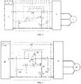
FIG. 1 is a structural diagram of a feedback current control device according to an embodiment of the present invention. As shown inFIG. 1 , a power circuit between adriver 20 and abattery 30 may include: a feed circuit for thebattery 30 to supply electricity to thedriver 20; and a current capture circuit configured to divide a feedback current delivered by thedriver 20. The feedback current control device may include: a feedback current capture module 40, located on the current capture circuit and configured to capture the feedback current delivered by thedriver 20; afirst switch module 50, located on the current capture circuit and configured to turn on or off the current capture circuit; and acontrol module 60, wherein thecontrol module 60 includes: afirst receiving unit 62, configured to receive a first voltage at one end of thedriver 20 and a second voltage at one end of thebattery 30 on the feed circuit and a temperature of thebattery 30; and afirst control unit 64, configured to, according to a difference between the first voltage and the second voltage and the temperature of the battery, perform the following operations: controlling thefirst switch module 50 to turn on the current capture circuit under the condition that the difference between the first voltage and the second voltage is greater than a preset voltage and the temperature of the battery is less than or equal to a preset temperature, such that the feedback current is captured by the feedback current capture module 40, as shown inFIG. 2 . - Wherein a first end of the feed circuit is connected to a positive electrode of the
driver 20, and the other end of the feed circuit is connected to a positive electrode of thebattery 30. One end of the current capture circuit is connected to a point B on the feed circuit (any point on the feed circuit between a current output terminal of a second switch module 10 and the driver 20) (i.e., the positive electrode of the driver), and the other end of the current capture circuit is connected to a negative electrode of the battery, which is used for restraining a pulse feedback current from being charged to the battery when the battery is at low temperature, thereby preventing the battery from lithium precipitation, meanwhile, maximally absorbing the feedback energy, saving the energy and prolonging the battery life of equipment. - Specifically, when the temperature of the battery is lower than the preset temperature (for example, 0°C), the generated feedback energy (feedback current) is completely converted into thermal energy by the feedback current capture module 40 (for example, a braking resistor 42) to be consumed, and may not be delivered to the battery (may not charge the battery). Hence, in the embodiment, when the battery is at low temperature (for example, the temperature of the battery is less than 0°C), the battery does not need to be heated, which thereby does not affect the user's operation experience, and is beneficial to prolonging the battery life of the aerial equipment. Since the battery does not need to be heated, a user can operate equipment without waiting for the battery to be preheated, which makes the equipment more convenient to operate. In addition, when the equipment works, the temperature of the battery can be maintained to be 0°C or above without consuming the energy of the battery, so that the consumption of electric energy is reduced, which is conducive to saving energy and prolonging the battery life of the equipment.
- The power circuit further includes: a charging circuit for the driver to deliver the feedback current to the battery. The charging circuit is connected in parallel with the feed circuit, so as to form a main circuit between the driver and the battery. Correspondingly, the feedback current control device further includes: a second switch module 10. The second switch module 10 is located on the charging circuit and configured to turn on or off the charging circuit. To (completely) capture the feedback currents by the above process, it is required to control the second switch module 10 to turn off the charging circuit in advance and then perform the above process of capturing the feedback currents.
- When the battery is at room temperature, there may be a risk of overcharging if a fully charged battery is charged, and overcharging may easily cause lithium precipitation and thermal runaway of the battery. When an aerial equipment goes downhill at high speed, potential energy of equipment is converted into kinetic energy, and the excess kinetic energy is converted into electric energy which is used to charge the battery. For a fully charged battery, this long-time charging may result in overcharging the battery. In order to avoid overcharging, in the embodiment, the first switch module disposed on the current capture circuit is used to regulate the charging current of the charging circuit.
- Specifically, the
control module 60 further includes: a second receiving unit (not shown), configured to receive a present allowable charging current of thebattery 30. The present allowable charging current may be determined according to a present SOC (State of Charge) of thebattery 30. Correspondingly, thefirst control unit 64 is further configured to, under the condition that the difference between the first voltage and the second voltage is greater than the preset voltage (for example, 0.3 V) and the temperature of the battery is greater than the preset temperature (for example, 0°C), perform the following operations: controlling the second switch module 10 to turn on the charging circuit; and controlling thefirst switch module 50 to turn on the current capture circuit, and controlling thedriver 20 to charge thebattery 30 with the present allowable charging current and through the charging circuit by regulating on-off time of thefirst switch module 50. Thefirst switch module 50 may be a second field-effect transistor 52 (which may be referred to as anMOS transistor 52, as shown inFIG. 3 or FIG. 4 ). - Wherein the difference between the first voltage and the second voltage being greater than the preset voltage indicates that an electric motor generates a heavy feedback current, and the temperature of the battery being greater than the preset temperature (for example, 0°C) indicates that charging the battery at the moment may not pose a risk of lithium precipitation. In this case, the control module 60 (for example, CPU 66) may be used to control a pulse-width modulation (PWM) duty cycle by adopting a PI control algorithm, so as to control the on-off time of the
MOS transistor 52, thereby realizing the precise division control on the feedback current and further ensuring that the charging current of the charging circuit is equal to the present allowable charging current of the battery (which may be determined according to actual requirements, and may be a preset percentage of a maximum present allowable charging current corresponding to the present SOC (for example, any value from 80% to 100%, specifically 98%)). Therefore, in the embodiment, the battery may be charged according to the current allowable charging current (as close as possible to the maximum present allowable charging current but not exceeding the maximum present allowable charging current), and the excess feedback energy is consumed by the feedback current capture module 40 on the current capture circuit, which avoids the overcharging phenomenon and thereby is beneficial to prolonging the battery life. - Wherein the feedback current capture module 40 may be an energy consumption module (not shown) or an energy storage module (not shown). Specifically, the energy consumption module (not shown) may be a
braking resistor 42, as shown inFIG. 3 or FIG. 4 . Wherein thebraking resistor 42 needs to not only satisfy the requirement of a braking distance, but also ensure that a regenerated electromotive force is less than a protection voltage of the driver, and its value may be determined according to existing algorithms. The energy storage module (not shown) may be a supercapacitor (not shown) or a storage battery (not shown). In an embodiment, the feedback current capture module 40 adopts thebraking resistor 42, which has the advantages of low cost and small size (easy installation on an aerial equipment with a limited space). In another embodiment, the feedback current capture module 40 adopts an energy storage module, which has the following advantages: after the feedback energy is absorbed, the feed circuit may supply electricity to the battery, which makes the energy utilization rate higher and is more conducive to saving energy and prolonging the battery life of the equipment. - The feedback current control device may further include: a third switch module 70. The third switch module 70 is located on the feed circuit, connected in parallel with the second switch module 10, and configured to unidirectionally turn on the feed circuit so as to only allow the
battery 30 to supply electricity to thedriver 20. That is, the third switch module 70 on the feed circuit is mainly used to realize the charging function; and the second switch module 10 on the charging circuit is mainly used to block the pulse charging current. - Wherein the second switch module 10 may be a contactor 12 (as shown in
FIG. 3 ), a combination of a first diode (not shown) and a contactor (not shown) connected in series, or a first field-effect transistor 14 (which may be referred to as anMOS transistor 14, as shown inFIG. 4 ). Specifically, under the condition that the second switch module 10 is the first field-effect transistor 14, the first field-effect transistor 14 has a first chip. Correspondingly, thecontrol module 60 may further include: a third control unit (not shown), configured to, under the condition that the third switch module 70 fails, control the first chip of the first field-effect transistor 14 to unidirectionally turn on the charging circuit so as to only allow thebattery 30 to supply electricity to thedriver 20. - Wherein the third switch module 70 is a second diode (not shown) or a third field-effect transistor 72 (as shown in
FIG. 3 or FIG. 4 ). The third field-effect transistor 72 has a second chip. Correspondingly, thecontrol module 60 may further include: a fourth control unit (not shown), configured to control the second chip of the third field-effect transistor 72 (which may be referred to as an MOS transistor 72) to unidirectionally turn on the feed circuit so as to only allow thebattery 30 to supply electricity to thedriver 20. In an embodiment, the third switch module 70 is a second diode (not shown), which has the advantage of low cost. In another embodiment, the third switch module 70 is a third field-effect transistor 72 (as shown inFIG. 3 or FIG. 4 ), which has the following advantages: the size is smaller, which is beneficial to the arrangement of a circuit board; and an internal resistance is smaller: when the current of the feed circuit is heavier, the voltage drop is smaller (thereby less heat is generated), so less feedback energy is dissipated. - A brief description will be given by taking the feedback current control device shown in
FIG. 3 as an example. On the main circuit (i.e., a power loop) between thedriver 20 and thebattery 30, thecontactor 12 and theMOS transistor 72 connected in parallel are arranged; and on the current capture circuit for capturing the feedback current, theMOS transistor 52 and thebraking resistor 42 are arranged. - The
MOS transistor 72 is configured with a dedicated control chip, which has the characteristic of unidirectional conduction of a diode and can prevent the feedback current from flowing to the battery from the driver. Thecontactor 12 is controlled to be on or off by theCPU 66. In normal cases (i.e., when the SOC is greater than the preset percentage or the temperature of the battery is less than or equal to the preset temperature, for example, when SOC>95% (the preset percentage may be other reasonable values, for example, 90%) or the temperature of the battery is less than or equal to 0°C (the preset temperature may be other reasonable values, and may be set according to actual needs)), an off state is present. When the temperature of the battery is greater than the preset temperature (for example, 0°C), that is, when the feedback current is allowed to be delivered to the battery 30 (the battery is in a state of being charged), thecontactor 12 is controlled to turn on the charging circuit where thecontactor 12 is located, so that the feedback current can flow from thedriver 20 to thebattery 30 through the charging circuit. In the meanwhile, in order to prevent the current flowing to thebattery 30 from being too heavy (for example, exceeding the present allowable charging current of the battery 30), theCPU 66 may be used to control the PWM duty cycle by the PI control algorithm to regulate the on-off time of theMOS transistor 52, thereby controlling thedriver 20 to charge thebattery 30 with the present allowable charging current. - A brief description will be given by taking the feedback current control device shown in
FIG. 4 as an example. On the main circuit (i.e., a power loop) between thedriver 20 and thebattery 30, theMOS transistor 14 and theMOS transistor 72 connected in parallel are arranged. The MOS transistor on the power loop adopts a redundant design, that is, two MOS transistors are connected in parallel with each other and then connected in series in the power loop. When the aerial equipment is under heavy current conditions (for example, in a state of climbing a slope with a certain angle (for example, 45 degrees)), the redundant design can reduce the voltage drop in the power loop, which thereby not only can lower the temperature of the MOS transistor so as to prolong the service life of the MOS transistor, but also can avoid the consumption of the feedback energy such that the battery can maximally absorb the braking energy. Moreover, on the current capture circuit for capturing the feedback current, theMOS transistor 52 and thebraking resistor 42 are arranged. - In an embodiment, the
MOS transistor 72 is configured with a dedicated control chip, which has the characteristic of unidiretional conduction of a diode and can prevent the feedback current from flowing to the battery from the driver. TheMOS transistor 14 is controlled to be on or off by theCPU 66. In normal cases, an off state is present. When the temperature of the battery is greater than the preset temperature (for example, 0°C), that is, when the feedback current is allowed to be delivered to the battery 30 (the battery is in a state of being charged), theMOS transistor 14 is controlled to turn on the charging circuit where theMOS transistor 14 is located, so that the feedback current can flow from thedriver 20 to thebattery 30 through the charging circuit. In the meanwhile, in order to prevent the current flowing to thebattery 30 from being too heavy (for example, exceeding the present allowable charging current of the battery 30), theCPU 66 may be used to control the PWM duty cycle by the PI control algorithm to regulate the on-off time of theMOS transistor 52, thereby controlling thedriver 20 to charge thebattery 30 with the present allowable charging current. - In another embodiment, the
MOS transistor 72 is configured with a dedicated control chip, which has the characteristic of unidirectional conduction of a diode and can prevent the feedback current from flowing to the battery from the driver. When the feedback current control device is under normal operating conditions, theMOS transistor 14 may play the same role as theMOS transistor 14 in the previous embodiment, that is, may allow thedriver 20 to charge thebattery 30 with the present allowable charging current. However, under the condition that theMOS transistor 72 fails, since theMOS transistor 14 is also configured with a dedicated control chip which has the characteristic of unidirectional conduction of a diode, theCPU 66 may be used to control the chip to unidirectionally turn on the charging circuit where theMOS transistor 14 is located. Thereby, on the one hand, thebattery 30 can continue supplying electricity to thedriver 20, and on the other hand, the feedback current can be prevented from flowing from the driver to the battery. When the temperature of the battery is greater than the preset temperature (for example, 0°C), operations similar to those in the previous embodiment may be performed, and details will not be repeated here. - In the above embodiment, the feedback current control device has a braking control function, which can effectively restrain damage to the battery caused by the pulse feedback current when the battery is at low temperature. That is, when the aerial equipment slows down or goes downhill, if the temperature of the
battery 30 is lower than the preset temperature (for example, 0°C), the feedback current is blocked by theMOS transistor 72 and cannot flow to the battery, thereby effectively restraining the phenomenon of charging with the pulse feedback current when the battery is at low temperature, greatly reducing the probability of lithium precipitation of the battery and the risk of thermal runaway of the battery and enhancing the safety of the battery. - On the premise of satisfying a minimum braking distance, a maximum value of the pulse feedback current is reduced as much as possible, so as to flatten the waveforms of the pulse feedback current, thereby reducing the impact on the battery. In the embodiment of the present invention, an electricity generation current of the electric motor may be controlled. The details are given in the description below.
- The
control module 60 may further include: a determining unit (not shown), configured to determine an electricity generation current of anelectric motor 80 according to a target speed and an actual speed of theelectric motor 80 and braking time of the aerial equipment; and a sending unit (not shown), configured to send the determined electricity generation current to thedriver 20, so as to allow thedriver 20 to control theelectric motor 80 to generate electricity with the electricity generation current. - The determining unit (not shown) configured to determine the electricity generation current may include: determining that the electricity generation current is a maximum electricity generation current under the condition that the target speed, the actual speed and the braking time satisfy a preset condition, wherein the preset condition is that the braking time is less than preset braking time or a difference between the target speed and the actual speed is greater than a preset speed difference; or determining the electricity generation current according to a minimum electricity generation current, a maximum allowable braking time and a maximum electricity generation current under the condition that the target speed, the actual speed and the braking time do not satisfy the preset condition.
- Wherein the minimum electricity generation current means that electricity generation with the current can satisfy the minimum braking distance under non-extreme conditions (for example, running at a speed of 6km/h on a flat ground). The minimum electricity generation current may usually be expressed as a percentage of the maximum electricity generation current.
- Wherein the determining unit (not shown) configured to determine the electricity generation current according to the minimum electricity generation current, the maximum allowable braking time and the maximum electricity generation current may include: determining the electricity generation current according to the minimum electricity generation current Imin, the maximum allowable braking time Tmax, the maximum electricity generation current Imax and the following formula (1),

- Specifically, the electricity generation current may be calculated according to the following rules.
- When the braking time is less than Is (for example, the preset braking time), the electricity generation current= 100%Imax. A sudden stop operation usually requires a short braking distance and thereby the maximum braking power is required. Usually, the electricity generation current for the sudden stop operation is set to be 100%Imax.
- When the difference between the target speed and the actual speed is large (for example, the difference may be 500 rpm, and the preset speed difference may be 200 rpm (but this preset speed is not limited to 200 rpm)), the electricity generation current=100%Imax. At the moment, the resistance of the aerial equipment is large, the aerial equipment may be go uphill, and kinetic energy that can be converted into electric energy decreases. The generated power is not high, so the peak feedback current is not high.
- In other cases, the electricity generation current may be calculated according to the above formula (1).
- After the electricity generation current is calculated, the
control module 60 sends the electricity generation current to thedriver 20 through a CAN bus, and thedriver 20 controls theelectric motor 80 to generate electricity with the electricity generation current. Thus, in the mebodiment, without affecting the braking performance, the feedback energy can be controlled to be output smoothly, the impact feedback current is decreased, and thereby, the impact on the battery is effectively alleviated. - Under the condition that the second switch module 10 and the third switch module 70 both fail, an aerial equipment under normal working conditions cannot be moved to an emergency maintenance station and repaired by relevant maintenance personnel since the
battery 30 cannot supply electricity to the aerial equipment. - In the embodiment of the present invention, a bypass switch connected in parallel with the second switch module may be further provided, and supplying electricity to the driver from the battery may be maintained by closing the bypass switch. Specifically, the feedback current control device may further include: a
bypass switch 90. Thebypass switch 90 is connected in parallel with the second switch module 10, as shown inFIG. 4 . Correspondingly, thecontrol module 60 may further include: a fifth control unit (not shown), configured to, under the condition that the second switch module 10 and the third switch module 70 both fail, control thebypass switch 90 to be closed such that thebattery 30 supplies electricity to thedriver 20. - Of course, the control units (for example, the first control unit, the second control unit, the third control unit, the fourth control unit and the fifth control unit) in the above embodiments may be independent control units, or may be integrated in a same control unit.
- The feedback current control device may further include: a first voltage sensor (not shown), configured to acquire the first voltage at one end of the
driver 20 on the main circuit; and a second voltage sensor (not shown), configured to acquire the second voltage at one end of thebattery 30 on the main circuit. The first voltage sensor (not shown) and the second voltage sensor (not shown) may be avoltmeter 100 and avoltmeter 110 respectively. - Specifically, a charging control process for the battery is explained and described below by taking the feedback current control device shown in
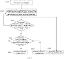
FIG. 4 as an example, as shown inFIG. 5 . - As shown in
FIG. 5 , the charging control process for the battery may include steps S501-S508 as follows. - In step S501, powering an aerial equipment.
- In step S502, acquiring, by a CPU, a temperature of a battery, a present allowable charging current of the battery, voltages UA and UB at two ends of an
MOS transistor 72, a target speed and an actual speed of an electric motor, and braking time. - The
CPU 66 acquires state information of thebattery 30 through aCAN controller 120, which includes a temperature of thebattery 30, a real-time SOC of thebattery 30 and an allowable charging current in this real-time SOC (present allowable charging current for short). The state information is provided by a BMS (battery management system) 140 of thebattery 30. TheCPU 66 acquires a voltage (UA) at a front end of anMOS transistor 72, a voltage (UB) at a rear end of theMOS transistor 72, a target speed and an actual speed of anelectric motor 80, and braking time (also referred to as slowing-down time) of an aerial equipment from an A/D converter 130. - In step S503, performing, by the CPU, electricity generation control.
- Electricity generation control: the
CPU 66 may determine an electricity generation current of theelectric motor 80 according the target speed and the actual speed of theelectric motor 80 and the braking time of the aerial equipment (for the specific process, reference can be made to the description above, and details will not be repeated here); and then theCPU 66 sends the determined electricity generation current to adriver 20, and thedriver 20 controls theelectric motor 80 to generate electricity based on the electricity generation current. - The purpose of controlling the electricity generation current is to reduce a maximum value of the pulse feedback current as much as possible while satisfying the minimum braking distance so as to flatten the waveform of the pulse feedback current, thereby reducing the impact on the battery and facilitating the precise control of the control system. Another benefit of controlling the electricity generation current is that a peak voltage at a point B can be suppressed, thereby avoiding the overvoltage alarm of the driver.
- In step S504, determining, by the CPU, whether a difference between the voltage UB and the voltage UA is greater than a preset voltage, if so, step S505 is performed; otherwise, step S502 is performed again.
- If the difference between the voltage UB and the voltage UA is greater than the preset voltage (for example, 0.3 V), it indicates that the electric motor generates a heavy feedback current, and then step S505 needs to be further performed to determine, according to the temperature of the battery, whether the battery can be charged, otherwise, it indicates that the electric motor does not generate a heavy feedback current, and step S502 is performed again.
- In step S505, determining, by the CPU, whether the temperature of the battery is less than or equal to a preset temperature, if so, step S506 is performed, otherwise, step S507 is performed.
- If the difference between the voltage UB and the voltage UA is greater than the preset voltage (for example, 0.3 V) and the temperature of the battery is less than or equal to the preset temperature (for example, 0°C), it indicates that charging the battery at the moment may pose a risk of lithium precipitation. At the moment, step S506 is performed to perform braking control. That is, the heavy feedback current is diverted to the current capture circuit, and the feedback current is consumed, for example, through a
braking resistor 42, that is, charging is not performed on thebattery 30. - If the difference between the voltage UB and the voltage UA is greater than the preset voltage (for example, 0.3 V) and the temperature of the battery is greater than the preset temperature (for example, 0°C), it indicates that charging the battery at the moment may not pose a risk of lithium precipitation. At the moment, step S507 is performed to perform the charging control. That is, the battery is charged with the limited charging current.
- In step S506, performing, by the CPU, braking control.
- When the difference between the voltage UB and the voltage UA is greater than the preset voltage (for example, 0.3 V) and the temperature of the battery is less than or equal to the preset temperature (for example, 0°C), braking control is enabled.
- Braking control: the
CPU 66 controls anMOS transistor 14 to turn off the charging circuit, and controls anMOS transistor 52 to turn on the current capture circuit (i.e., a braking loop). At the moment, all the feedback currents are consumed by thebraking resistor 42, thereby avoiding charging the battery. The purpose of the braking control is to prevent the risk of lithium precipitation of the battery caused by the pulse feedback current at low temperature. - In step S507, performing, by the CPU, charging control.
- When the difference between the voltage UB and the voltage UA is greater than the preset voltage (for example, 0.3 V) and the temperature of the battery is greater than the preset temperature (for example, 0°C), charging control is enabled.
- Charging control: the
CPU 66 controls theMOS transistor 14 to turn on the charging circuit, controls theMOS transistor 52 to turn on the current capture circuit (i.e., a braking loop), and meanwhile, controls on-off time of the MOS transistor 7 by controlling a PWM duty cycle by a PI control algorithm by taking the present allowable charging current of the battery as a target value, thereby regulating the current division of the feedback current in the current capture circuit, i.e., realizing precise control on the braking current, and finally ensuring that the charging current is equal to the present allowable charging current of the battery. The purpose of the charging control is to avoid overcharging. - In conclusion, in an inventive way, the first switch module is controlled to turn on the feedback current capture module to capture the feedback current under the condition that the difference between the first voltage at one end of the driver and the second voltage at one end of the battery on the feed circuit is greater than the preset voltage and the temperature of the battery is less than the preset temperature (for example, 0°C). Thereby, when charging is performed at low temperature, the feedback current capture module can capture all the feedback currents, so that the risk of lithium precipitation of the battery caused by the pulse feedback current when charging is performed at low temperature can be effectively avoided, thereby greatly reducing the probability of lithium precipitation of the battery and the risk of thermal runaway of the battery and enhancing the safety of the battery.
- An embodiment of the present invention further provides an aerial equipment, including: the feedback current control device.
- For specific details and benefits of the aerial equipment in the embodiment of the present invention, reference can be made to the above description for the feedback current control device, which will not be repeated here.
- The preferred embodiments of the present invention have been described in detail above in conjunction with the accompanying drawings, but the present invention is not limited to the specific details in the above embodiments, and various simple variations may be made to the technical solutions of the present invention within the scope of the technical idea of the present invention. These simple variations are all within the protection scope of the present invention.
- It should be further noted that the specific technical features described in the above specific embodiments may be combined in any suitable manner in the case of no contradiction. In order to avoid unnecessary repetition, various possible combinations of the present invention will not be further described.
- In addition, any combination of the various embodiments of the present invention can be made as long as it does not deviate from the idea of the present invention, and it should also be regarded as the contents disclosed by the present invention.
Claims (12)
- A feedback current control device, wherein a power circuit between a driver and a battery comprises: a feed circuit configured to supply electricity to the driver from the battery; and a current capture circuit configured to divide a feedback current delivered by the driver, and
the feedback current control device comprises:a feedback current capture module, located on the current capture circuit and configured to capture the feedback current;a first switch module, located on the current capture circuit and configured to turn on or off the current capture circuit; anda control module, comprising:a first receiving unit, configured to receive a first voltage at one end of the driver and a second voltage at one end of the battery on the feed circuit and a temperature of the battery; anda first control unit, configured to, according to a difference between the first voltage and the second voltage and the temperature of the battery, to perform the following operations:
controlling the first switch module to turn on the current capture circuit under the condition that the difference between the first voltage and the second voltage is greater than a preset voltage and the temperature of the battery is less than or equal to a preset temperature, such that the feedback current is captured by the feedback current capture module. - The feedback current control device according to claim 1, wherein the power circuit further comprises: a charging circuit configured to deliver feedback current to the battery by the driver, the charging circuit being connected in parallel with the feed circuit,the feedback current control device further comprises: a second switch module, located on the charging circuit and configured to turn on or off the charging circuit,the control module further comprises: a second receiving unit, configured to receive a present allowable charging current of the battery, andthe first control unit is further configured to, under the condition that the difference between the first voltage and the second voltage is greater than the preset voltage and the temperature of the battery is greater than the preset temperature, to perform the following operations:controlling the second switch module to turn on the charging circuit; andcontrolling the first switch module to turn on the current capture circuit, and controlling the driver to charge the battery with the present allowable charging current and through the charging circuit by regulating on-off time of the first switch module.
- The feedback current control device according to claim 2, further comprising:
a third switch module, located on the feed circuit, connected in parallel with the second switch module, and configured to unidirectionally turn on the feed circuit so as to only allow the battery to supply electricity to the driver. - The feedback current control device according to claim 3, wherein the second switch module is a contactor, a combination of a first diode and a contactor connected in series, or a first field-effect transistor.
- The feedback current control device according to claim 4, wherein the first field-effect transistor has a first chip, and
the control module further comprises: a third control unit, configured to, under the condition that the third switch module fails, control the first chip of the first field-effect transistor to unidirectionally turn on the charging circuit so as to only allow the battery to supply electricity to the driver. - The feedback current control device according to claim 3, wherein the first switch module is a second field-effect transistor; andthe third switch module is a second diode or a third field-effect transistor, wherein the third field-effect transistor has a second chip, andthe control module further comprises: a fourth control unit, configured to control the second chip of the third field-effect transistor to unidirectionally turn on the feed circuit so as to only allow the battery to supply electricity to the driver.
- The feedback current control device according to claim 3, wherein the feedback current control device further comprises:a bypass switch, wherein the bypass switch is connected in parallel with the second switch module, andthe control module further comprise: a fifth control unit, configured to, under the condition that the second switch module and the third switch module both fail, control the bypass switch to be closed such that the battery supplies electricity to the driver.
- The feedback current control device according to claim 1, wherein the control module further comprises:a determining unit, configured to determine an electricity generation current of an electric motor according a target speed of the electric motor, an actual speed of the electric motor and braking time of an aerial equipment; anda sending unit, configured to send the determined electricity generation current to the driver, so as to allow the driver to control the electric motor to generate electricity with the electricity generation current.
- The feedback current control device according to claim 8, wherein the determining unit configured to determine the electricity generation current comprises:determining that the electricity generation current is a maximum electricity generation current under the condition that the target speed, the actual speed and the braking time satisfy a preset condition, wherein the preset condition is that the braking time is less than preset braking time or a difference between the target speed and the actual speed is greater than a preset speed difference; ordetermining the electricity generation current according to a minimum electricity generation current, a maximum allowable braking time and the maximum electricity generation current under the condition that the target speed, the actual speed and the braking time do not satisfy the preset condition.
- The feedback current control device according to claim 1, wherein the feedback current capture module is an energy consumption module or an energy storage module.
- The feedback current control device according to claim 10, wherein the energy consumption module is a braking resistor.
- An aerial equipment, comprising: the feedback current control device according to any one of claims 1-11.
Applications Claiming Priority (2)
| Application Number | Priority Date | Filing Date | Title |
|---|---|---|---|
| CN202010768953.8A CN112078368B (en) | 2020-08-03 | 2020-08-03 | Feedback current control device and overhead working truck |
| PCT/CN2021/084038 WO2022027984A1 (en) | 2020-08-03 | 2021-03-30 | Feedback current control device and aerial platform truck |
Publications (2)
| Publication Number | Publication Date |
|---|---|
| EP4063173A1 true EP4063173A1 (en) | 2022-09-28 |
| EP4063173A4 EP4063173A4 (en) | 2023-07-26 |
Family
ID=73734797
Family Applications (1)
| Application Number | Title | Priority Date | Filing Date |
|---|---|---|---|
| EP21854536.6A Pending EP4063173A4 (en) | 2020-08-03 | 2021-03-30 | Feedback current control device and aerial platform truck |
Country Status (6)
| Country | Link |
|---|---|
| US (1) | US20230037348A1 (en) |
| EP (1) | EP4063173A4 (en) |
| CN (1) | CN112078368B (en) |
| AU (1) | AU2021322990B2 (en) |
| CA (1) | CA3166311A1 (en) |
| WO (1) | WO2022027984A1 (en) |
Families Citing this family (8)
| Publication number | Priority date | Publication date | Assignee | Title |
|---|---|---|---|---|
| CN112671075A (en) * | 2021-01-14 | 2021-04-16 | 格力博(江苏)股份有限公司 | Electric tool |
| CN112078368B (en) * | 2020-08-03 | 2022-03-29 | 湖南中联重科智能高空作业机械有限公司 | Feedback current control device and overhead working truck |
| CN112910068A (en) * | 2020-11-23 | 2021-06-04 | 湖南中联重科智能高空作业机械有限公司 | Control device for motor driver, motor driver and overhead working truck |
| CN112644288B (en) * | 2020-12-25 | 2022-04-12 | 中国第一汽车股份有限公司 | Vehicle energy recovery and distribution method and device, vehicle and storage medium |
| CN114537220B (en) * | 2022-02-28 | 2024-04-09 | 重庆金康赛力斯新能源汽车设计院有限公司 | Overcharge prevention system and method for power battery |
| WO2024051201A1 (en) * | 2022-09-07 | 2024-03-14 | 湖南中联重科智能高空作业机械有限公司 | Control system for downhill working condition, and elevated work vehicle |
| CN116587891A (en) * | 2023-03-03 | 2023-08-15 | 宇通客车股份有限公司 | Method and device for improving endurance of pure electric vehicle |
| CN116198371B (en) * | 2023-03-27 | 2023-10-31 | 深圳市南霸科技有限公司 | Electric automobile charge control system |
Family Cites Families (15)
| Publication number | Priority date | Publication date | Assignee | Title |
|---|---|---|---|---|
| JP2010183667A (en) * | 2009-02-03 | 2010-08-19 | Toyo Electric Mfg Co Ltd | Controller for electric rolling stock |
| FR2975243B1 (en) * | 2011-05-13 | 2013-04-26 | Michelin Soc Tech | DEVICE AND METHOD FOR MANAGING THE ELECTRIC BRAKE OF A VEHICLE |
| JP6439322B2 (en) * | 2014-08-27 | 2018-12-19 | 三菱自動車工業株式会社 | Regenerative control device for hybrid vehicle |
| JP6552456B2 (en) * | 2016-06-13 | 2019-07-31 | 本田技研工業株式会社 | Control device for electric lawn mower |
| CN107512179A (en) * | 2016-06-15 | 2017-12-26 | 北京科易动力科技有限公司 | A kind of electrokinetic cell system and the control method for the system |
| KR102145524B1 (en) * | 2016-06-22 | 2020-08-18 | 주식회사 엘지화학 | Driver circuit for an electric vehicle and control method for the same |
| US10017169B1 (en) * | 2016-12-30 | 2018-07-10 | Textron Innovations Inc. | Controlling an electric brake of a utility vehicle which has a lithium battery management system |
| CN206650483U (en) * | 2017-04-14 | 2017-11-17 | 江西韵动新能源科技有限公司 | A kind of compound power battery pack of high energy fast charge modularization |
| CN110549912A (en) * | 2018-03-29 | 2019-12-10 | 比亚迪股份有限公司 | Vehicle battery temperature adjusting method and system and vehicle |
| CN108973780A (en) * | 2018-09-20 | 2018-12-11 | 南京恒天领锐汽车有限公司 | A kind of novel pure electric heavy type automobile brake resistance control device |
| CN209600281U (en) * | 2018-12-28 | 2019-11-08 | 湖南铁道职业技术学院 | Regenerating braking energy blended absorbent device applied to electric car |
| CN111409465B (en) * | 2020-03-31 | 2022-01-25 | 潍柴动力股份有限公司 | Regenerative braking control method and control device for vehicle |
| CN112078368B (en) * | 2020-08-03 | 2022-03-29 | 湖南中联重科智能高空作业机械有限公司 | Feedback current control device and overhead working truck |
| CN112259829B (en) * | 2020-09-27 | 2022-01-28 | 湖南中联重科智能高空作业机械有限公司 | Lithium battery system and aerial working vehicle |
| CN112260342B (en) * | 2020-09-27 | 2022-01-28 | 湖南中联重科智能高空作业机械有限公司 | Lithium battery system and aerial working vehicle |
-
2020
- 2020-08-03 CN CN202010768953.8A patent/CN112078368B/en active Active
-
2021
- 2021-03-30 WO PCT/CN2021/084038 patent/WO2022027984A1/en unknown
- 2021-03-30 AU AU2021322990A patent/AU2021322990B2/en active Active
- 2021-03-30 EP EP21854536.6A patent/EP4063173A4/en active Pending
- 2021-03-30 US US17/790,598 patent/US20230037348A1/en active Pending
- 2021-03-30 CA CA3166311A patent/CA3166311A1/en active Pending
Also Published As
| Publication number | Publication date |
|---|---|
| EP4063173A4 (en) | 2023-07-26 |
| AU2021322990B2 (en) | 2024-01-04 |
| CN112078368B (en) | 2022-03-29 |
| WO2022027984A1 (en) | 2022-02-10 |
| US20230037348A1 (en) | 2023-02-09 |
| AU2021322990A1 (en) | 2022-07-21 |
| CN112078368A (en) | 2020-12-15 |
| CA3166311A1 (en) | 2022-02-10 |
Similar Documents
| Publication | Publication Date | Title |
|---|---|---|
| EP4063173A1 (en) | Feedback current control device and aerial platform truck | |
| CN107776416B (en) | Rail transit hybrid power circuit, energy storage power pack and power supply method thereof | |
| US20180361877A1 (en) | Automotive Hybrid Energy Supply System and Method and Hybrid Energy Automobile | |
| EP1977495B1 (en) | Energy storage system for electric or hybrid vehicle | |
| US7960855B2 (en) | System and method for providing power control of an energy storage system | |
| US9221345B2 (en) | Battery charging device for motor vehicle | |
| JP4274772B2 (en) | High voltage energy adjustment type conversion circuit | |
| CN109910641B (en) | Efficient composite energy storage system for pure electric vehicle and control method of efficient composite energy storage system | |
| CN112260342B (en) | Lithium battery system and aerial working vehicle | |
| CN112259829B (en) | Lithium battery system and aerial working vehicle | |
| CN213367428U (en) | Circuit device for controlling feedback current and overhead working truck | |
| EP4064420A1 (en) | Lithium battery system and overhead working truck | |
| CN104242435A (en) | Unmanned aerial vehicle power supply system and unmanned aerial vehicle | |
| CN105083268B (en) | A kind of control method of fuel cell hybrid car control system | |
| CN213305000U (en) | Circuit device for capturing feedback current and overhead working truck | |
| CN113997811A (en) | Charger of power battery and charging method thereof | |
| CN213304999U (en) | Circuit device for intercepting feedback current and overhead working truck | |
| CN117728721A (en) | Descending control system and aerial work platform | |
| CN220447669U (en) | New energy automobile charging system | |
| CN219029176U (en) | Braking energy recovery device and overhead contact system tramcar | |
| CN212343410U (en) | Circuit structure for adjusting overhigh energy feedback voltage of electric vehicle | |
| JP2004080907A (en) | Motor drive unit | |
| CN117087439A (en) | Power control system and method for electric wheel dumper | |
| CN115946547A (en) | Hybrid power system based on carbon-based capacitor battery and control method | |
| CN111953058A (en) | Circuit structure for adjusting overhigh energy feedback voltage of electric vehicle |
Legal Events
| Date | Code | Title | Description |
|---|---|---|---|
| STAA | Information on the status of an ep patent application or granted ep patent |
Free format text: STATUS: THE INTERNATIONAL PUBLICATION HAS BEEN MADE |
|
| PUAI | Public reference made under article 153(3) epc to a published international application that has entered the european phase |
Free format text: ORIGINAL CODE: 0009012 |
|
| STAA | Information on the status of an ep patent application or granted ep patent |
Free format text: STATUS: REQUEST FOR EXAMINATION WAS MADE |
|
| 17P | Request for examination filed |
Effective date: 20220623 |
|
| AK | Designated contracting states |
Kind code of ref document: A1 Designated state(s): AL AT BE BG CH CY CZ DE DK EE ES FI FR GB GR HR HU IE IS IT LI LT LU LV MC MK MT NL NO PL PT RO RS SE SI SK SM TR |
|
| A4 | Supplementary search report drawn up and despatched |
Effective date: 20230623 |
|
| RIC1 | Information provided on ipc code assigned before grant |
Ipc: B60L 58/15 20190101ALI20230619BHEP Ipc: B60L 53/22 20190101ALI20230619BHEP Ipc: B60L 15/20 20060101ALI20230619BHEP Ipc: B60L 58/24 20190101ALI20230619BHEP Ipc: B60L 7/22 20060101ALI20230619BHEP Ipc: B60L 1/00 20060101ALI20230619BHEP Ipc: H02J 7/14 20060101ALI20230619BHEP Ipc: H02J 7/00 20060101ALI20230619BHEP Ipc: B60L 3/00 20190101ALI20230619BHEP Ipc: B60L 7/10 20060101AFI20230619BHEP |
|
| DAV | Request for validation of the european patent (deleted) | ||
| DAX | Request for extension of the european patent (deleted) | ||
| STAA | Information on the status of an ep patent application or granted ep patent |
Free format text: STATUS: EXAMINATION IS IN PROGRESS |
|
| 17Q | First examination report despatched |
Effective date: 20240306 |