EP4063161B1 - Control method, control system of hybrid vehicle, and hybrid vehicle - Google Patents
Control method, control system of hybrid vehicle, and hybrid vehicle Download PDFInfo
- Publication number
- EP4063161B1 EP4063161B1 EP22158548.2A EP22158548A EP4063161B1 EP 4063161 B1 EP4063161 B1 EP 4063161B1 EP 22158548 A EP22158548 A EP 22158548A EP 4063161 B1 EP4063161 B1 EP 4063161B1
- Authority
- EP
- European Patent Office
- Prior art keywords
- hydraulic pressure
- engine
- instruction
- pressure
- engagement element
- Prior art date
- Legal status (The legal status is an assumption and is not a legal conclusion. Google has not performed a legal analysis and makes no representation as to the accuracy of the status listed.)
- Active
Links
Images




Classifications
-
- B—PERFORMING OPERATIONS; TRANSPORTING
- B60—VEHICLES IN GENERAL
- B60W—CONJOINT CONTROL OF VEHICLE SUB-UNITS OF DIFFERENT TYPE OR DIFFERENT FUNCTION; CONTROL SYSTEMS SPECIALLY ADAPTED FOR HYBRID VEHICLES; ROAD VEHICLE DRIVE CONTROL SYSTEMS FOR PURPOSES NOT RELATED TO THE CONTROL OF A PARTICULAR SUB-UNIT
- B60W20/00—Control systems specially adapted for hybrid vehicles
- B60W20/10—Controlling the power contribution of each of the prime movers to meet required power demand
- B60W20/15—Control strategies specially adapted for achieving a particular effect
-
- B—PERFORMING OPERATIONS; TRANSPORTING
- B60—VEHICLES IN GENERAL
- B60W—CONJOINT CONTROL OF VEHICLE SUB-UNITS OF DIFFERENT TYPE OR DIFFERENT FUNCTION; CONTROL SYSTEMS SPECIALLY ADAPTED FOR HYBRID VEHICLES; ROAD VEHICLE DRIVE CONTROL SYSTEMS FOR PURPOSES NOT RELATED TO THE CONTROL OF A PARTICULAR SUB-UNIT
- B60W20/00—Control systems specially adapted for hybrid vehicles
- B60W20/40—Controlling the engagement or disengagement of prime movers, e.g. for transition between prime movers
-
- B—PERFORMING OPERATIONS; TRANSPORTING
- B60—VEHICLES IN GENERAL
- B60K—ARRANGEMENT OR MOUNTING OF PROPULSION UNITS OR OF TRANSMISSIONS IN VEHICLES; ARRANGEMENT OR MOUNTING OF PLURAL DIVERSE PRIME-MOVERS IN VEHICLES; AUXILIARY DRIVES FOR VEHICLES; INSTRUMENTATION OR DASHBOARDS FOR VEHICLES; ARRANGEMENTS IN CONNECTION WITH COOLING, AIR INTAKE, GAS EXHAUST OR FUEL SUPPLY OF PROPULSION UNITS IN VEHICLES
- B60K6/00—Arrangement or mounting of plural diverse prime-movers for mutual or common propulsion, e.g. hybrid propulsion systems comprising electric motors and internal combustion engines
- B60K6/20—Arrangement or mounting of plural diverse prime-movers for mutual or common propulsion, e.g. hybrid propulsion systems comprising electric motors and internal combustion engines the prime-movers consisting of electric motors and internal combustion engines, e.g. HEVs
- B60K6/22—Arrangement or mounting of plural diverse prime-movers for mutual or common propulsion, e.g. hybrid propulsion systems comprising electric motors and internal combustion engines the prime-movers consisting of electric motors and internal combustion engines, e.g. HEVs characterised by apparatus, components or means specially adapted for HEVs
- B60K6/36—Arrangement or mounting of plural diverse prime-movers for mutual or common propulsion, e.g. hybrid propulsion systems comprising electric motors and internal combustion engines the prime-movers consisting of electric motors and internal combustion engines, e.g. HEVs characterised by apparatus, components or means specially adapted for HEVs characterised by the transmission gearings
- B60K6/365—Arrangement or mounting of plural diverse prime-movers for mutual or common propulsion, e.g. hybrid propulsion systems comprising electric motors and internal combustion engines the prime-movers consisting of electric motors and internal combustion engines, e.g. HEVs characterised by apparatus, components or means specially adapted for HEVs characterised by the transmission gearings with the gears having orbital motion
-
- B—PERFORMING OPERATIONS; TRANSPORTING
- B60—VEHICLES IN GENERAL
- B60K—ARRANGEMENT OR MOUNTING OF PROPULSION UNITS OR OF TRANSMISSIONS IN VEHICLES; ARRANGEMENT OR MOUNTING OF PLURAL DIVERSE PRIME-MOVERS IN VEHICLES; AUXILIARY DRIVES FOR VEHICLES; INSTRUMENTATION OR DASHBOARDS FOR VEHICLES; ARRANGEMENTS IN CONNECTION WITH COOLING, AIR INTAKE, GAS EXHAUST OR FUEL SUPPLY OF PROPULSION UNITS IN VEHICLES
- B60K6/00—Arrangement or mounting of plural diverse prime-movers for mutual or common propulsion, e.g. hybrid propulsion systems comprising electric motors and internal combustion engines
- B60K6/20—Arrangement or mounting of plural diverse prime-movers for mutual or common propulsion, e.g. hybrid propulsion systems comprising electric motors and internal combustion engines the prime-movers consisting of electric motors and internal combustion engines, e.g. HEVs
- B60K6/22—Arrangement or mounting of plural diverse prime-movers for mutual or common propulsion, e.g. hybrid propulsion systems comprising electric motors and internal combustion engines the prime-movers consisting of electric motors and internal combustion engines, e.g. HEVs characterised by apparatus, components or means specially adapted for HEVs
- B60K6/38—Arrangement or mounting of plural diverse prime-movers for mutual or common propulsion, e.g. hybrid propulsion systems comprising electric motors and internal combustion engines the prime-movers consisting of electric motors and internal combustion engines, e.g. HEVs characterised by apparatus, components or means specially adapted for HEVs characterised by the driveline clutches
- B60K6/387—Actuated clutches, i.e. clutches engaged or disengaged by electric, hydraulic or mechanical actuating means
-
- B—PERFORMING OPERATIONS; TRANSPORTING
- B60—VEHICLES IN GENERAL
- B60K—ARRANGEMENT OR MOUNTING OF PROPULSION UNITS OR OF TRANSMISSIONS IN VEHICLES; ARRANGEMENT OR MOUNTING OF PLURAL DIVERSE PRIME-MOVERS IN VEHICLES; AUXILIARY DRIVES FOR VEHICLES; INSTRUMENTATION OR DASHBOARDS FOR VEHICLES; ARRANGEMENTS IN CONNECTION WITH COOLING, AIR INTAKE, GAS EXHAUST OR FUEL SUPPLY OF PROPULSION UNITS IN VEHICLES
- B60K6/00—Arrangement or mounting of plural diverse prime-movers for mutual or common propulsion, e.g. hybrid propulsion systems comprising electric motors and internal combustion engines
- B60K6/20—Arrangement or mounting of plural diverse prime-movers for mutual or common propulsion, e.g. hybrid propulsion systems comprising electric motors and internal combustion engines the prime-movers consisting of electric motors and internal combustion engines, e.g. HEVs
- B60K6/42—Arrangement or mounting of plural diverse prime-movers for mutual or common propulsion, e.g. hybrid propulsion systems comprising electric motors and internal combustion engines the prime-movers consisting of electric motors and internal combustion engines, e.g. HEVs characterised by the architecture of the hybrid electric vehicle
- B60K6/48—Parallel type
-
- B—PERFORMING OPERATIONS; TRANSPORTING
- B60—VEHICLES IN GENERAL
- B60W—CONJOINT CONTROL OF VEHICLE SUB-UNITS OF DIFFERENT TYPE OR DIFFERENT FUNCTION; CONTROL SYSTEMS SPECIALLY ADAPTED FOR HYBRID VEHICLES; ROAD VEHICLE DRIVE CONTROL SYSTEMS FOR PURPOSES NOT RELATED TO THE CONTROL OF A PARTICULAR SUB-UNIT
- B60W10/00—Conjoint control of vehicle sub-units of different type or different function
- B60W10/02—Conjoint control of vehicle sub-units of different type or different function including control of driveline clutches
-
- B—PERFORMING OPERATIONS; TRANSPORTING
- B60—VEHICLES IN GENERAL
- B60W—CONJOINT CONTROL OF VEHICLE SUB-UNITS OF DIFFERENT TYPE OR DIFFERENT FUNCTION; CONTROL SYSTEMS SPECIALLY ADAPTED FOR HYBRID VEHICLES; ROAD VEHICLE DRIVE CONTROL SYSTEMS FOR PURPOSES NOT RELATED TO THE CONTROL OF A PARTICULAR SUB-UNIT
- B60W10/00—Conjoint control of vehicle sub-units of different type or different function
- B60W10/02—Conjoint control of vehicle sub-units of different type or different function including control of driveline clutches
- B60W10/023—Fluid clutches
-
- B—PERFORMING OPERATIONS; TRANSPORTING
- B60—VEHICLES IN GENERAL
- B60W—CONJOINT CONTROL OF VEHICLE SUB-UNITS OF DIFFERENT TYPE OR DIFFERENT FUNCTION; CONTROL SYSTEMS SPECIALLY ADAPTED FOR HYBRID VEHICLES; ROAD VEHICLE DRIVE CONTROL SYSTEMS FOR PURPOSES NOT RELATED TO THE CONTROL OF A PARTICULAR SUB-UNIT
- B60W10/00—Conjoint control of vehicle sub-units of different type or different function
- B60W10/04—Conjoint control of vehicle sub-units of different type or different function including control of propulsion units
- B60W10/06—Conjoint control of vehicle sub-units of different type or different function including control of propulsion units including control of combustion engines
-
- B—PERFORMING OPERATIONS; TRANSPORTING
- B60—VEHICLES IN GENERAL
- B60W—CONJOINT CONTROL OF VEHICLE SUB-UNITS OF DIFFERENT TYPE OR DIFFERENT FUNCTION; CONTROL SYSTEMS SPECIALLY ADAPTED FOR HYBRID VEHICLES; ROAD VEHICLE DRIVE CONTROL SYSTEMS FOR PURPOSES NOT RELATED TO THE CONTROL OF A PARTICULAR SUB-UNIT
- B60W10/00—Conjoint control of vehicle sub-units of different type or different function
- B60W10/04—Conjoint control of vehicle sub-units of different type or different function including control of propulsion units
- B60W10/08—Conjoint control of vehicle sub-units of different type or different function including control of propulsion units including control of electric propulsion units, e.g. motors or generators
-
- B—PERFORMING OPERATIONS; TRANSPORTING
- B60—VEHICLES IN GENERAL
- B60W—CONJOINT CONTROL OF VEHICLE SUB-UNITS OF DIFFERENT TYPE OR DIFFERENT FUNCTION; CONTROL SYSTEMS SPECIALLY ADAPTED FOR HYBRID VEHICLES; ROAD VEHICLE DRIVE CONTROL SYSTEMS FOR PURPOSES NOT RELATED TO THE CONTROL OF A PARTICULAR SUB-UNIT
- B60W30/00—Purposes of road vehicle drive control systems not related to the control of a particular sub-unit, e.g. of systems using conjoint control of vehicle sub-units
- B60W30/18—Propelling the vehicle
- B60W30/192—Mitigating problems related to power-up or power-down of the driveline, e.g. start-up of a cold engine
-
- B—PERFORMING OPERATIONS; TRANSPORTING
- B60—VEHICLES IN GENERAL
- B60K—ARRANGEMENT OR MOUNTING OF PROPULSION UNITS OR OF TRANSMISSIONS IN VEHICLES; ARRANGEMENT OR MOUNTING OF PLURAL DIVERSE PRIME-MOVERS IN VEHICLES; AUXILIARY DRIVES FOR VEHICLES; INSTRUMENTATION OR DASHBOARDS FOR VEHICLES; ARRANGEMENTS IN CONNECTION WITH COOLING, AIR INTAKE, GAS EXHAUST OR FUEL SUPPLY OF PROPULSION UNITS IN VEHICLES
- B60K6/00—Arrangement or mounting of plural diverse prime-movers for mutual or common propulsion, e.g. hybrid propulsion systems comprising electric motors and internal combustion engines
- B60K6/20—Arrangement or mounting of plural diverse prime-movers for mutual or common propulsion, e.g. hybrid propulsion systems comprising electric motors and internal combustion engines the prime-movers consisting of electric motors and internal combustion engines, e.g. HEVs
- B60K6/22—Arrangement or mounting of plural diverse prime-movers for mutual or common propulsion, e.g. hybrid propulsion systems comprising electric motors and internal combustion engines the prime-movers consisting of electric motors and internal combustion engines, e.g. HEVs characterised by apparatus, components or means specially adapted for HEVs
- B60K6/26—Arrangement or mounting of plural diverse prime-movers for mutual or common propulsion, e.g. hybrid propulsion systems comprising electric motors and internal combustion engines the prime-movers consisting of electric motors and internal combustion engines, e.g. HEVs characterised by apparatus, components or means specially adapted for HEVs characterised by the motors or the generators
- B60K2006/268—Electric drive motor starts the engine, i.e. used as starter motor
-
- B—PERFORMING OPERATIONS; TRANSPORTING
- B60—VEHICLES IN GENERAL
- B60K—ARRANGEMENT OR MOUNTING OF PROPULSION UNITS OR OF TRANSMISSIONS IN VEHICLES; ARRANGEMENT OR MOUNTING OF PLURAL DIVERSE PRIME-MOVERS IN VEHICLES; AUXILIARY DRIVES FOR VEHICLES; INSTRUMENTATION OR DASHBOARDS FOR VEHICLES; ARRANGEMENTS IN CONNECTION WITH COOLING, AIR INTAKE, GAS EXHAUST OR FUEL SUPPLY OF PROPULSION UNITS IN VEHICLES
- B60K6/00—Arrangement or mounting of plural diverse prime-movers for mutual or common propulsion, e.g. hybrid propulsion systems comprising electric motors and internal combustion engines
- B60K6/20—Arrangement or mounting of plural diverse prime-movers for mutual or common propulsion, e.g. hybrid propulsion systems comprising electric motors and internal combustion engines the prime-movers consisting of electric motors and internal combustion engines, e.g. HEVs
- B60K6/42—Arrangement or mounting of plural diverse prime-movers for mutual or common propulsion, e.g. hybrid propulsion systems comprising electric motors and internal combustion engines the prime-movers consisting of electric motors and internal combustion engines, e.g. HEVs characterised by the architecture of the hybrid electric vehicle
- B60K6/48—Parallel type
- B60K2006/4825—Electric machine connected or connectable to gearbox input shaft
-
- B—PERFORMING OPERATIONS; TRANSPORTING
- B60—VEHICLES IN GENERAL
- B60W—CONJOINT CONTROL OF VEHICLE SUB-UNITS OF DIFFERENT TYPE OR DIFFERENT FUNCTION; CONTROL SYSTEMS SPECIALLY ADAPTED FOR HYBRID VEHICLES; ROAD VEHICLE DRIVE CONTROL SYSTEMS FOR PURPOSES NOT RELATED TO THE CONTROL OF A PARTICULAR SUB-UNIT
- B60W2510/00—Input parameters relating to a particular sub-units
- B60W2510/06—Combustion engines, Gas turbines
- B60W2510/0604—Throttle position
-
- B—PERFORMING OPERATIONS; TRANSPORTING
- B60—VEHICLES IN GENERAL
- B60W—CONJOINT CONTROL OF VEHICLE SUB-UNITS OF DIFFERENT TYPE OR DIFFERENT FUNCTION; CONTROL SYSTEMS SPECIALLY ADAPTED FOR HYBRID VEHICLES; ROAD VEHICLE DRIVE CONTROL SYSTEMS FOR PURPOSES NOT RELATED TO THE CONTROL OF A PARTICULAR SUB-UNIT
- B60W2510/00—Input parameters relating to a particular sub-units
- B60W2510/06—Combustion engines, Gas turbines
- B60W2510/0638—Engine speed
-
- B—PERFORMING OPERATIONS; TRANSPORTING
- B60—VEHICLES IN GENERAL
- B60W—CONJOINT CONTROL OF VEHICLE SUB-UNITS OF DIFFERENT TYPE OR DIFFERENT FUNCTION; CONTROL SYSTEMS SPECIALLY ADAPTED FOR HYBRID VEHICLES; ROAD VEHICLE DRIVE CONTROL SYSTEMS FOR PURPOSES NOT RELATED TO THE CONTROL OF A PARTICULAR SUB-UNIT
- B60W2510/00—Input parameters relating to a particular sub-units
- B60W2510/08—Electric propulsion units
- B60W2510/081—Speed
-
- B—PERFORMING OPERATIONS; TRANSPORTING
- B60—VEHICLES IN GENERAL
- B60W—CONJOINT CONTROL OF VEHICLE SUB-UNITS OF DIFFERENT TYPE OR DIFFERENT FUNCTION; CONTROL SYSTEMS SPECIALLY ADAPTED FOR HYBRID VEHICLES; ROAD VEHICLE DRIVE CONTROL SYSTEMS FOR PURPOSES NOT RELATED TO THE CONTROL OF A PARTICULAR SUB-UNIT
- B60W2510/00—Input parameters relating to a particular sub-units
- B60W2510/08—Electric propulsion units
- B60W2510/083—Torque
-
- B—PERFORMING OPERATIONS; TRANSPORTING
- B60—VEHICLES IN GENERAL
- B60W—CONJOINT CONTROL OF VEHICLE SUB-UNITS OF DIFFERENT TYPE OR DIFFERENT FUNCTION; CONTROL SYSTEMS SPECIALLY ADAPTED FOR HYBRID VEHICLES; ROAD VEHICLE DRIVE CONTROL SYSTEMS FOR PURPOSES NOT RELATED TO THE CONTROL OF A PARTICULAR SUB-UNIT
- B60W2510/00—Input parameters relating to a particular sub-units
- B60W2510/24—Energy storage means
- B60W2510/242—Energy storage means for electrical energy
- B60W2510/244—Charge state
-
- B—PERFORMING OPERATIONS; TRANSPORTING
- B60—VEHICLES IN GENERAL
- B60W—CONJOINT CONTROL OF VEHICLE SUB-UNITS OF DIFFERENT TYPE OR DIFFERENT FUNCTION; CONTROL SYSTEMS SPECIALLY ADAPTED FOR HYBRID VEHICLES; ROAD VEHICLE DRIVE CONTROL SYSTEMS FOR PURPOSES NOT RELATED TO THE CONTROL OF A PARTICULAR SUB-UNIT
- B60W2520/00—Input parameters relating to overall vehicle dynamics
- B60W2520/10—Longitudinal speed
-
- B—PERFORMING OPERATIONS; TRANSPORTING
- B60—VEHICLES IN GENERAL
- B60W—CONJOINT CONTROL OF VEHICLE SUB-UNITS OF DIFFERENT TYPE OR DIFFERENT FUNCTION; CONTROL SYSTEMS SPECIALLY ADAPTED FOR HYBRID VEHICLES; ROAD VEHICLE DRIVE CONTROL SYSTEMS FOR PURPOSES NOT RELATED TO THE CONTROL OF A PARTICULAR SUB-UNIT
- B60W2520/00—Input parameters relating to overall vehicle dynamics
- B60W2520/10—Longitudinal speed
- B60W2520/105—Longitudinal acceleration
-
- B—PERFORMING OPERATIONS; TRANSPORTING
- B60—VEHICLES IN GENERAL
- B60W—CONJOINT CONTROL OF VEHICLE SUB-UNITS OF DIFFERENT TYPE OR DIFFERENT FUNCTION; CONTROL SYSTEMS SPECIALLY ADAPTED FOR HYBRID VEHICLES; ROAD VEHICLE DRIVE CONTROL SYSTEMS FOR PURPOSES NOT RELATED TO THE CONTROL OF A PARTICULAR SUB-UNIT
- B60W2710/00—Output or target parameters relating to a particular sub-units
- B60W2710/02—Clutches
- B60W2710/021—Clutch engagement state
-
- B—PERFORMING OPERATIONS; TRANSPORTING
- B60—VEHICLES IN GENERAL
- B60W—CONJOINT CONTROL OF VEHICLE SUB-UNITS OF DIFFERENT TYPE OR DIFFERENT FUNCTION; CONTROL SYSTEMS SPECIALLY ADAPTED FOR HYBRID VEHICLES; ROAD VEHICLE DRIVE CONTROL SYSTEMS FOR PURPOSES NOT RELATED TO THE CONTROL OF A PARTICULAR SUB-UNIT
- B60W2710/00—Output or target parameters relating to a particular sub-units
- B60W2710/06—Combustion engines, Gas turbines
-
- B—PERFORMING OPERATIONS; TRANSPORTING
- B60—VEHICLES IN GENERAL
- B60W—CONJOINT CONTROL OF VEHICLE SUB-UNITS OF DIFFERENT TYPE OR DIFFERENT FUNCTION; CONTROL SYSTEMS SPECIALLY ADAPTED FOR HYBRID VEHICLES; ROAD VEHICLE DRIVE CONTROL SYSTEMS FOR PURPOSES NOT RELATED TO THE CONTROL OF A PARTICULAR SUB-UNIT
- B60W2710/00—Output or target parameters relating to a particular sub-units
- B60W2710/08—Electric propulsion units
-
- B—PERFORMING OPERATIONS; TRANSPORTING
- B60—VEHICLES IN GENERAL
- B60W—CONJOINT CONTROL OF VEHICLE SUB-UNITS OF DIFFERENT TYPE OR DIFFERENT FUNCTION; CONTROL SYSTEMS SPECIALLY ADAPTED FOR HYBRID VEHICLES; ROAD VEHICLE DRIVE CONTROL SYSTEMS FOR PURPOSES NOT RELATED TO THE CONTROL OF A PARTICULAR SUB-UNIT
- B60W2710/00—Output or target parameters relating to a particular sub-units
- B60W2710/08—Electric propulsion units
- B60W2710/081—Speed
-
- B—PERFORMING OPERATIONS; TRANSPORTING
- B60—VEHICLES IN GENERAL
- B60W—CONJOINT CONTROL OF VEHICLE SUB-UNITS OF DIFFERENT TYPE OR DIFFERENT FUNCTION; CONTROL SYSTEMS SPECIALLY ADAPTED FOR HYBRID VEHICLES; ROAD VEHICLE DRIVE CONTROL SYSTEMS FOR PURPOSES NOT RELATED TO THE CONTROL OF A PARTICULAR SUB-UNIT
- B60W2710/00—Output or target parameters relating to a particular sub-units
- B60W2710/08—Electric propulsion units
- B60W2710/083—Torque
-
- Y—GENERAL TAGGING OF NEW TECHNOLOGICAL DEVELOPMENTS; GENERAL TAGGING OF CROSS-SECTIONAL TECHNOLOGIES SPANNING OVER SEVERAL SECTIONS OF THE IPC; TECHNICAL SUBJECTS COVERED BY FORMER USPC CROSS-REFERENCE ART COLLECTIONS [XRACs] AND DIGESTS
- Y02—TECHNOLOGIES OR APPLICATIONS FOR MITIGATION OR ADAPTATION AGAINST CLIMATE CHANGE
- Y02T—CLIMATE CHANGE MITIGATION TECHNOLOGIES RELATED TO TRANSPORTATION
- Y02T10/00—Road transport of goods or passengers
- Y02T10/60—Other road transportation technologies with climate change mitigation effect
- Y02T10/62—Hybrid vehicles
Definitions
- the present invention relates to a control method and a control system of a hybrid vehicle including an engine and a motor as a driving source, and a friction engagement element (clutch) which switches transmission and interruption of torque between the engine and the motor.
- a friction engagement element clutch
- hybrid vehicles including an engine (internal combustion engine), a motor provided downstream of the engine on a power transmission path to vehicle wheels, a first clutch provided between the engine and the motor to be disengageable, and a second clutch provided between the motor and the vehicle wheels (drive wheels) to be disengageable, are known.
- This type of hybrid vehicle is switchable of a traveling mode between a mode in which the hybrid vehicle travels using motor torque without using engine torque (EV traveling mode), and a mode in which the hybrid vehicle travels using at least the engine torque (engine traveling mode or hybrid (HV) traveling mode).
- JP2000-255285A discloses a technology for this kind of hybrid vehicle, in which when starting-up an engine while traveling using only a motor, the motor speed is increased while a second clutch (start clutch) is slip-controlled, and then when the motor speed reaches a given speed, a first clutch (engine clutch) is engaged.
- the first clutch provided between the engine and the motor is shifted from a released state to the engaged state. Accordingly, motor torque is transmitted to the engine via the first clutch, and the engine is started by being cranked by the motor.
- the present invention is made in view of solving the above problems, and one purpose thereof is reducing a vehicle shock when starting-up an engine of the hybrid vehicle while securing a startup response of the engine.
- a method of controlling a hybrid vehicle includes an engine, a motor, a friction engagement element provided between the engine and the motor to be capable of being engaged and/or disengaged by hydraulic pressure, and a hydraulic control circuit configured to control the hydraulic pressure to be applied to the friction engagement element.
- the method includes the steps of controlling the hydraulic pressure to be applied to the friction engagement element in response to a startup demand of the engine in a stopped state during traveling of the hybrid vehicle so that the friction engagement element is shifted from a released or disengaged state to one of a given slipping state and an engaged state, and controlling the motor and the engine so that the motor cranks the engine to start, one or both of during and after the controlling the hydraulic pressure.
- the controlling the hydraulic pressure includes, when a target driving force of the hybrid vehicle is below a given value, setting an instruction hydraulic pressure for the hydraulic control circuit to a first hydraulic pressure and maintaining the first hydraulic pressure for a given period of time, then setting the instruction hydraulic pressure to a second hydraulic pressure and maintaining the second hydraulic pressure until the engine start is completed, and then setting the instruction hydraulic pressure to a third hydraulic pressure, the first hydraulic pressure being a pressure at which an increase rate in an engagement pressure at a start of engaging of the friction engagement element becomes below a given rate, the second hydraulic pressure being a pressure at which an engine-startup engagement pressure for transmitting torque required for the engine start is applied to the friction engagement element, and the third hydraulic pressure being a pressure for setting the friction engagement element to the engaged state.
- the controlling the hydraulic pressure includes, when the target driving force of the hybrid vehicle is above the given value, setting the instruction hydraulic pressure to the second hydraulic pressure without setting to the first hydraulic pressure, and maintaining the second hydraulic pressure until the engine start is completed, and then setting the instruction hydraulic pressure to the third hydraulic pressure.
- the instruction hydraulic pressure for the hydraulic control circuit in response to the startup demand of the engine, when controlling the hydraulic pressure to be applied to the friction engagement element, in the case where the target driving force of the hybrid vehicle is below the given value, the instruction hydraulic pressure for the hydraulic control circuit is set to the first hydraulic pressure at which the increase rate in the engagement pressure at the start of engaging of the friction engagement element becomes below the given rate, and it is maintained for the given period of time. Then, the instruction hydraulic pressure is set to the second hydraulic pressure, and it is maintained until the engine start is completed. Then, the instruction hydraulic pressure is set to the third hydraulic pressure and the friction engagement element is made into the engaged state.
- the target driving force is below the given value, and the suppression of the vehicle shock is to be prioritized over the startup response of the engine, the occurrence of the vehicle shock at the start of engaging of the friction engagement element to start the engine, can be avoided.
- the instruction hydraulic pressure is set to the second hydraulic pressure without setting to the first hydraulic pressure, and it is maintained until the engine start is completed. Therefore, when the target driving force is above the given value, and the improvement in the startup response of the engine is to be prioritized over the suppression of the vehicle shock, the engine can promptly be cranked to start in response to the issuance of the startup demand of the engine, and thus, the startup response of the engine can be secured.
- the vehicle shock can be suppressed while securing the startup response of the engine.
- the controlling the hydraulic pressure may include, when the start of the engine is demanded, first setting the instruction hydraulic pressure to a fourth hydraulic pressure at which an engagement pressure higher than the engine-startup engagement pressure is applied to the friction engagement element, and maintaining the fourth hydraulic pressure for a given period of time.
- the hydraulic oil can promptly be supplied to the friction engagement element immediately after the issuance of the startup demand of the engine, which improves the response of the friction engagement element in the subsequent control.
- the period of time during which the instruction hydraulic pressure is maintained at the fourth hydraulic pressure may be longer compared with when the target driving force is below the given value.
- the response of the friction engagement element can further be improved.
- the controlling the hydraulic pressure may include, when the target driving force is below the given value, after the setting the instruction hydraulic pressure to the first hydraulic pressure and maintaining for the given period of time, and before the setting the instruction hydraulic pressure to the second hydraulic pressure, setting the instruction hydraulic pressure to a fifth hydraulic pressure for making the friction engagement element stand by in a state immediately before engaging, and maintaining the fifth hydraulic pressure until a given condition is satisfied.
- the friction engagement element may be a normally-open clutch, the third hydraulic pressure may be higher than the second hydraulic pressure, and the second hydraulic pressure may be higher than the first hydraulic pressure.
- the friction engagement element may be a normally-closed clutch
- the third hydraulic pressure may be higher than the second hydraulic pressure
- the second hydraulic pressure may be higher than the first hydraulic pressure
- a control system of a hybrid vehicle which includes an engine and a motor, a friction engagement element provided between the engine and the motor to be disengageable by hydraulic pressure, a hydraulic control circuit configured to control the hydraulic pressure to be applied to the friction engagement element, and a control device configured to control the engine, the motor, the friction engagement element, and the hydraulic control circuit.
- the control device is configured to control the hydraulic pressure to be applied to the friction engagement element in response to a startup demand of the engine in a stopped state during traveling of the hybrid vehicle so that the friction engagement element is shifted from a released state to one of a given slipping state and an engaged state, and control the motor and the engine so that the motor cranks the engine to start, one or both of during and after the control of the hydraulic pressure.
- the control device controls the hydraulic pressure, and when a target driving force of the hybrid vehicle is below a given value, the control device sets an instruction hydraulic pressure for the hydraulic control circuit to a first hydraulic pressure and maintains the first hydraulic pressure for a given period of time, then sets the instruction hydraulic pressure to a second hydraulic pressure and maintains the second hydraulic pressure until the engine startup is completed, and then sets the instruction hydraulic pressure to a third hydraulic pressure, the first hydraulic pressure being a pressure at which an increase rate in an engagement pressure at a start of engaging of the friction engagement element becomes below a given rate, the second hydraulic pressure being a pressure at which an engine-startup engagement pressure for transmitting torque required for the engine start is applied to the friction engagement element, and the third hydraulic pressure being a pressure for setting the friction engagement element to the engaged state.
- the control device sets the instruction hydraulic pressure to the second hydraulic pressure without setting to the first hydraulic pressure, and maintains the second hydraulic pressure until the engine start is completed, and then sets the instruction hydraulic pressure to the third hydraulic pressure.
- Fig. 1 is a diagram illustrating a schematic configuration of a hybrid vehicle according to this embodiment.
- a hybrid vehicle 1 mainly includes an engine 2 (e.g., a gasoline engine), a motor (an electric motor) 4, a battery 5, a transmission 6, a powertrain system 8, a drive shaft 10, and vehicle wheels (drive wheels) 12.
- the engine 2 generates torque for driving the hybrid vehicle 1.
- the motor 4 is particularly provided downstream of the engine 2 on a power transmission path of the hybrid vehicle 1, and generates torque for driving the hybrid vehicle 1.
- the battery 5 sends and receives electric power to/from the motor 4 via, for example, an inverter (not illustrated).
- the transmission 6 may be provided downstream of the motor 4 on the power transmission path of the hybrid vehicle 1, and change a rotational speed of the engine 2 and/or the motor 4.
- the powertrain system 8 particularly transmits the torque downstream from the transmission 6, and the drive shaft 10 particularly drives the vehicle wheels 12 by the torque from the powertrain system 8.
- An output shaft of the engine 2 and a rotational shaft of the motor 4 may be coaxially coupled together by a shaft AX1 via a first clutch CL1 which is capable of being engaged and/or disengaged (connected and/or disconnected) by hydraulic pressure.
- This first clutch CL1 (friction engagement element) switches transmission and interruption of the torque between the engine 2 and the motor 4.
- the first clutch CL1 is comprised of, for example, a dry multi-plate clutch or a wet multi-plate clutch which is changeable of a transmission torque capacity by a successive or phased control of a flow rate and/or a pressure of clutch hydraulic oil by a hydraulic control circuit 14.
- the first clutch CL1 may be configured as a normally-open clutch which is released or disengaged (released state or disengaged state) when the hydraulic pressure is not applied, or a normally-closed clutch which is engaged (engaged state) when the hydraulic pressure is not applied.
- the hydraulic control circuit 14 may further be provided with a hydraulic pump which is driven by the engine 2 or a motor (not illustrated), solenoid valves which control hydraulic pressure to be applied to the first clutch CL1 and a second clutch CL2, and oil passages which connect the valves to the first clutch CL1 and the second clutch CL2, respectively.
- the rotational shaft of the motor 4 and a rotational shaft of the transmission 6 may be coaxially coupled together by a shaft AX2.
- the transmission 6 is internally provided with one or more planetary gear set(s) each including a sun gear S1, a ring gear R1, a pinion gear P1 (planetary gear), and a carrier C1, and friction engagement elements (e.g., a clutch and a brake).
- the transmission 6 is an automatic transmission having a function of automatically switching a gear stage (gear ratio) according to vehicle speed and/or engine speed.
- the ring gear R1 is particularly disposed to be concentric with the sun gear S1, and the pinion gear P1 is particularly disposed between the sun gear S1 and the ring gear R1 to mesh with the sun gear S1 and the ring gear R1.
- the carrier C1 particularly holds the pinion gear P1 to be rotatable as well as revolvable about the sun gear S1.
- the transmission 6 may be internally provided with the second clutch CL2 which is disengageable (disconnectable).
- the second clutch CL2 can switch transmission and interruption of torque between the upstream side (the engine 2 and the motor 4) and the downstream side (the vehicle wheels 12, etc.) of the transmission 6.
- the second clutch CL2 may be comprised of, for example, a dry multi-plate clutch or a wet multi-plate clutch which is changeable of a transmission torque capacity by a successive or phased control of a flow rate and/or a pressure of clutch hydraulic oil by the hydraulic control circuit 14.
- the second clutch CL2 is comprised of a plurality of clutches used for switching various gear stages in the transmission 6. Further, although Fig.
- the transmission 6 includes a plurality of planetary gear sets.
- the friction engagement elements including the plurality of clutches (e.g., the second clutch CL2) and a plurality of brakes (not illustrated) to switch the power transmission path via each planetary gear set, for example, a plurality of forward gear stages and one reverse gear stage can be achieved.
- the powertrain system 8 particularly receives torque via an output shaft AX3 of the transmission 6.
- the powertrain system 8 is comprised of, for example, a differential gear which dividedly supplies the driving force to a pair of left and right vehicle wheels 12, and a final gear.
- the hybrid vehicle 1 as described above can switch a traveling mode by switching the engagement and release (disengagement) of the first clutch CL1. That is, the hybrid vehicle 1 includes a first traveling mode in which the first clutch CL1 is set to the released state (or the disengaged state) and the hybrid vehicle 1 travels using the torque of the motor 4 without using the torque of the engine 2, and a second traveling mode in which the first clutch CL1 is set to the engaged state and the hybrid vehicle 1 travels using at least the torque of the engine 2.
- the first traveling mode may be a so-called EV traveling mode
- the second traveling mode may include an engine traveling mode in which the hybrid vehicle 1 travels using only the torque of the engine 2, and a hybrid traveling mode (HV traveling mode) in which the hybrid vehicle 1 travels using both of the torque of the engine 2 and the torque of the motor 4.
- HV traveling mode hybrid traveling mode
- Fig. 2 is a block diagram illustrating an electric configuration of the hybrid vehicle according to this embodiment.
- a controller 20 particularly receives an input of signals from an engine speed sensor SN1, a motor speed sensor SN2, an accelerator opening sensor SN3, a vehicle speed sensor SN4, an acceleration sensor SN5, and/or an SOC sensor SN6.
- the engine speed sensor SN1 detects the speed of the engine 2.
- the motor speed sensor SN2 detects the speed of the motor 4.
- the accelerator opening sensor SN3 detects an accelerator opening corresponding to a depressed amount of an accelerator pedal by a driver.
- the vehicle speed sensor SN4 detects a vehicle speed of the hybrid vehicle 1.
- the acceleration sensor SN5 detects an acceleration of the hybrid vehicle 1 in a front-and-rear direction.
- the SOC sensor SN6 detects a state of charge (SOC) of the battery 5.
- the controller 20 is particularly comprised of a computer including one or more processor(s) 20a (typically, a central processing unit (CPU)), and memory 20b (e.g., ROM and RAM) which stores various programs which are interpretively executed on the processor 20a (including a basic control program such as an operation system (OS) and an application program actuated on the OS to implement a specific function) and various data.
- processor(s) 20a typically, a central processing unit (CPU)
- memory 20b e.g., ROM and RAM
- the controller 20 is an example of a "control device" according to the present invention, disclosure, and executes a "method of controlling the hybrid vehicle” according to the present invention.
- the controller 20 mainly controls the engine 2, the motor 4, and the hydraulic control circuit 14 by outputting control signals thereto based on detection signals from the sensors SN1-SN6 described above.
- the controller 20 controls the engine 2 to adjust an ignition timing, a fuel injection timing, and a fuel injection amount, controls the motor 4 to adjust the speed and the torque, and controls the hydraulic control circuit 14 to adjust the hydraulic pressure applied to the first and second clutches CL1 and CL2.
- the controller 20 controls a spark plug, a fuel injection valve, and a throttle valve of the engine 2, controls the motor 4 via the inverter, and controls the motor and the solenoid valves of the hydraulic control circuit 14.
- the controller 20 controls, by the hydraulic control circuit 14, the hydraulic pressure to be supplied to the first clutch CL1 so that the first clutch CL1 provided between the engine 2 and the motor 4 is shifted from the released state to a given slipping state or the engaged state. According to this, the torque of the motor 4 is transmitted to the engine 2 via the first clutch CL1 and the engine 2 is cranked by the motor 4, and thus the engine 2 being started-up. Further, during such a startup of the engine 2, the controller 20 may shift the second clutch CL2 provided between the motor 4 and the vehicle wheels 12 from the engaged state to a given slipping state.
- the vehicle shock includes deceleration of the vehicle by a kinetic energy of the traveling hybrid vehicle 1 being transmitted to the engine 2 side and used for the startup of the engine.
- the controller 20 when the first clutch CL1 is shifted from the released state to the slipping state or the engaged state, the controller 20 changes an instruction hydraulic pressure to the hydraulic control circuit 14 according to whether a target driving force of the hybrid vehicle 1 is below a given value.
- the target driving force is set based on an accelerator pedal operation by the driver, and a traveling situation of the hybrid vehicle 1 (including the vehicle speed, the acceleration, the gear stage, and the traveling mode). For example, when the target driving force is below the given value (hereinafter, referred to as a "normal mode"), suppression of the vehicle shock is prioritized over the startup response of the engine 2, and the controller 20 sets the instruction hydraulic pressure such that the first clutch CL1 is slowly shifted from the released state to the given slipping state.
- the controller 20 sets the instruction hydraulic pressure such that the first clutch CL1 is shifted from the released state to the given slipping state more rapidly compared with in the normal mode. Therefore, both of the securing of the startup response of the engine and the suppression of the vehicle shock can be achieved as necessary.
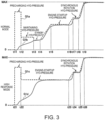
- FIG. 3 is a time chart illustrating the control of the normally open first clutch CL1.
- graph G1a indicates the instruction hydraulic pressure when the hydraulic pressure to be applied to the first clutch CL1 is instructed to the hydraulic control circuit 14 in the normal mode
- graph G1b indicates an actual hydraulic pressure applied to the first clutch CL1 in the normal mode
- Graph G1c indicates the instruction hydraulic pressure when the hydraulic pressure to be applied to the first clutch CL1 is instructed to the hydraulic control circuit 14 in the high response mode
- graph G1d indicates an actual hydraulic pressure applied to the first clutch CL1 in the high response mode.
- the controller 20 may temporarily increase, between the time 111 and a time 112, the instruction hydraulic pressure to a hydraulic pressure for precharging (precharging hydraulic pressure) in a stepped shape.
- the precharging hydraulic pressure is particularly an instruction hydraulic pressure (fourth hydraulic pressure) at which, when the actual hydraulic pressure of the first clutch CL1 reaches the precharging hydraulic pressure, an engagement pressure higher than an engagement pressure for transmitting torque required for the start of the engine 2 (engine-startup engagement pressure) can be generated and applied to the first clutch CL1.
- the precharging hydraulic pressure may be set according to a flow rate of the hydraulic oil required when filling to an oil chamber of the first clutch CL1.
- the period of time during which the instruction hydraulic pressure is set to the precharging hydraulic pressure (from the time 111 to the time t12) is set based on a capacity of the oil chamber of the first clutch CL1. In this manner, by temporarily setting the relatively high instruction hydraulic pressure immediately after the issuance of the startup demand of the engine 2, the hydraulic oil can promptly be filled in the oil chamber of the first clutch CL1, and a response of the first clutch CL1 in the subsequent control can be improved.
- the controller 20 temporarily lowers the instruction hydraulic pressure to a maintaining hydraulic pressure in a stepped shape.
- the maintaining hydraulic pressure is an instruction hydraulic pressure (first hydraulic pressure) at which, when the first clutch CL1 starts engaging while the instruction hydraulic pressure is at the maintaining hydraulic pressure, an increase rate in the engagement pressure is below a given rate.
- the controller 20 may temporarily lower the instruction hydraulic pressure to a standby hydraulic pressure in a stepped shape.
- the standby hydraulic pressure is an instruction hydraulic pressure (fifth hydraulic pressure) at which the first clutch CL1 stands-by in a state immediately before engaging.
- the controller 20 increases the instruction hydraulic pressure to an engine-startup hydraulic pressure, and maintains the engine-startup hydraulic pressure between a time t15 and a time t16 until the engine start is completed.
- the engine-startup hydraulic pressure is an instruction hydraulic pressure (second hydraulic pressure) at which the engine-startup engagement pressure for transmitting torque required for the engine start is generated and applied to the first clutch CL1.
- the controller 20 particularly increase the instruction hydraulic pressure to a hydraulic pressure for synchronizing rotation (synchronous rotation hydraulic pressure), and maintains the synchronous rotation hydraulic pressure between a time t17 and a time t18 until the speed of the engine 2 increases and a differential rotation between the motor 4 and the engine 2 becomes sufficiently small.
- the synchronous rotation hydraulic pressure is an instruction hydraulic pressure at which the first clutch CL1 is applied with a hydraulic pressure higher than the engine-startup hydraulic pressure and lower than the maximum hydraulic pressure applicable to the first clutch CL1.
- the controller 20 may increase the instruction hydraulic pressure to be the maximum hydraulic pressure at a time t19.
- the maximum hydraulic pressure is an instruction hydraulic pressure (third hydraulic pressure) for setting the first clutch CL1 to the engaged state.
- the controller 20 temporarily increases, between the time t21 and a time t22, the instruction hydraulic pressure to the precharging hydraulic pressure in a stepped shape.
- the period of time during which the instruction hydraulic pressure is maintained at the precharging hydraulic pressure is substantially the same between in the normal mode and in the high response mode, it may be set longer in the high response mode than in the normal mode. Accordingly, the response of the first clutch CL1 can further be improved.
- the controller 20 particularly lowers the instruction hydraulic pressure to the engine-startup hydraulic pressure in a stepped shape without setting to the maintaining hydraulic pressure and the standby hydraulic pressure, and maintains the engine-startup hydraulic pressure between the time t22 and a time t23 until the engine start is completed.
- the controller 20 particularly increases the instruction hydraulic pressure to the synchronous rotation hydraulic pressure, and maintains the synchronous rotation hydraulic pressure between a time t24 and a time t25 until the speed of the engine 2 increases and the differential rotation between the motor 4 and the engine 2 becomes sufficiently small. Then, when the speed of the engine 2 increases and the differential rotation between the motor 4 and the engine 2 becomes sufficiently small at the time t25, the controller 20 increases the instruction hydraulic pressure to be the maximum hydraulic pressure at a time t26.
- Fig. 4 is a time chart illustrating the control of the normally close first clutch CL1.
- graph G1e indicates the instruction hydraulic pressure when the hydraulic pressure to be applied to the first clutch CL1 is instructed to the hydraulic control circuit 14 in the normal mode
- graph G1f indicates an actual hydraulic pressure applied to the first clutch CL1 in the normal mode
- Graph G1g indicates the instruction hydraulic pressure when the hydraulic pressure to be applied to the first clutch CL1 is instructed to the hydraulic control circuit 14 in the high response mode
- graph G1h indicates an actual hydraulic pressure applied to the first clutch CL1 in the high response mode.
- the controller 20 In the normal mode, when the start of the engine 2 is demanded at a time t31, the controller 20 temporarily lowers, between the time t31 and a time t32, the instruction hydraulic pressure to the precharging hydraulic pressure in a stepped shape.
- the precharging hydraulic pressure is set according to a flow rate of the hydraulic oil required when discharging from the oil chamber of the first clutch CL1. Further, the period of time during which the instruction hydraulic pressure is set to the precharging hydraulic pressure (from the time t31 to the time t32) is set based on the capacity of the oil chamber of the first clutch CL1. In this manner, by temporarily setting the relatively low instruction hydraulic pressure immediately after the issuance of the startup demand of the engine 2, the hydraulic oil can promptly be discharged from the oil chamber of the first clutch CL1, and the response of the first clutch CL1 can be improved.
- the controller 20 temporarily increases the instruction hydraulic pressure to the maintaining hydraulic pressure in a stepped shape.
- the controller 20 temporarily increases the instruction hydraulic pressure to the standby hydraulic pressure in a stepped shape.
- the instruction hydraulic pressure similarly to the case where the first clutch CL1 is the normally-open clutch, when the start of the cranking of the engine 2 is required to be waited until the other devices become ready (e.g., until the second clutch CL2 is shifted from the engaged state to the given slipping state), the torque transmission between the motor 4 and the engine 2 is interrupted, and once the other devices become ready, the first clutch CL1 can promptly engage so that the cranking of the engine 2 is started.
- the controller 20 lowers the instruction hydraulic pressure to the engine-startup hydraulic pressure, and maintains the engine-startup hydraulic pressure between a time t35 and a time t36 until the startup of the engine 2 is completed.
- the controller 20 lowers the instruction hydraulic pressure to be the minimum hydraulic pressure ("0" in Fig. 4 ) at a time t37.
- the minimum hydraulic pressure is an instruction hydraulic pressure (third hydraulic pressure) for setting the first clutch CL1 to the engaged state.
- the controller 20 temporarily lowers, between the time t41 and a time t42, the instruction hydraulic pressure to the precharging hydraulic pressure in a stepped shape.
- the controller 20 increases the instruction hydraulic pressure to the engine-startup hydraulic pressure particularly in a stepped shape without setting to the maintaining hydraulic pressure and the standby hydraulic pressure, and maintains the engine-startup hydraulic pressure between the time t42 and a time t43 until the engine start is completed.
- the instruction hydraulic pressure similarly to the case where the first clutch CL1 is the normally-open clutch, the improvement in the startup response of the engine 2 is prioritized over the suppression of the vehicle shock, and the engine 2 can promptly be cranked to start when the startup of the engine 2 is demanded.
- the controller 20 lowers the instruction hydraulic pressure to be the minimum hydraulic pressure at a time t44.
- Fig. 5 is a flowchart illustrating the startup control according to this embodiment. This flow is repeatedly executed by the controller 20 at a given cycle.
- the controller 20 particularly acquires various information.
- the controller 20 particularly acquires the detection signals at least from the sensors SN1-SN6 described above.
- the controller 20 particularly determines whether the startup of the currently stopped engine 2 is demanded.
- this startup demand is issued when the driver demands a comparatively large acceleration in the EV traveling mode (i.e., the driver demands acceleration which requires the switching of the traveling mode from the EV traveling mode to the HV traveling mode).
- the startup demand is issued from a control system including the powertrain (hereinafter, this startup demand may suitably be referred to as a "system demand").
- This system demand is issued when the switching of the traveling mode from the EV traveling mode to the HV traveling mode is required according to the vehicle speed, the vehicle load, the battery state, and the engine temperature.
- the system demand may be issued when the driving force of only the motor 4 is insufficient to achieve the target driving force, when the battery 5 requires charging (when the SOC of the battery 5 is below a given value), and when engine braking by the engine 2 is required during deceleration.
- Step S101 if the controller 20 particularly determines that the startup demand is not issued (Step S101: NO), the controller 20 ends the processing related to the startup control. On the other hand, if the controller 20 particularly determines that the startup demand is issued (Step S101: YES), the controller 20 particularly starts shifting of the second clutch CL2 from the engaged state to the given slipping state, and proceeds to Step S102. At Step S102, the controller 20 particularly sets the instruction hydraulic pressure to the hydraulic control circuit 14 to the precharging hydraulic pressure, and maintains the precharging hydraulic pressure for a given period of time set in advance.
- Step S103 the controller 20 particularly determines whether the given period of time has elapsed after the setting of the instruction hydraulic pressure to the precharging hydraulic pressure, and the precharging is completed. As a result, if the controller 20 determines that the given time period has elapsed and the precharging is completed (Step S103: YES), the controller 20 proceeds to Step S104. On the other hand, if the controller 20 determines that the given time period has not elapsed and the precharging is not completed (Step S103: NO), the controller 20 returns to Step S102, and repeats the processing at Steps S102 and S103 until the precharging is completed.
- Step S104 the controller 20 particularly determines whether the target driving force of the hybrid vehicle 1 is below the given value (i.e., in the normal mode). As a result, if the controller 20 determines as the normal mode (Step S104: YES), the controller 20 proceeds to Step S105.
- Step S105 the controller 20 particularly sets the instruction hydraulic pressure to the maintaining hydraulic pressure, and maintains the maintaining hydraulic pressure for a given period of time.
- Step S106 the controller 20 particularly determines whether the given period of time has elapsed after the setting of the instruction hydraulic pressure to the maintaining hydraulic pressure. As a result, if the controller 20 determines that the given time period has elapsed (Step S106: YES), the controller 20 proceeds to Step S107. On the other hand, if the controller 20 determines that the given time period has not elapsed (Step S106: NO), the controller 20 returns to Step S105, and repeats the processing at Steps S105 and S106 until the given time period elapses.
- Step S107 the controller 20 particularly sets the instruction hydraulic pressure to the standby hydraulic pressure, and maintains the standby hydraulic pressure until a condition for completion of the standby is satisfied (e.g., until the second clutch CL2 is shifted from the engaged state to the given slipping state). Then, at Step S108, the controller 20 particularly determines whether the condition for the standby completion is satisfied. As a result, if the controller 20 determines that the condition is satisfied (e.g., the second clutch CL2 is shifted from the engaged state to the given slipping state) (Step S108: YES), the controller 20 proceeds to Steps S109 and S 110. On the other hand, if the controller 20 determines that the condition for the standby completion is not satisfied (Step S108: NO), the controller 20 returns to Step S107, and repeats the processing at Steps S107 and S108 until the condition is satisfied.
- Step S108 the controller 20 determines that the condition for the standby completion is not satisfied.
- Step S104 if the controller 20 does not determine as the normal mode where the target driving force of the hybrid vehicle 1 is below the given value (i.e., in the high response mode where the target driving force is above the given value) (Step S104: NO), the controller 20 omits the processing at Steps S105 to S108, and proceeds to Steps S109 and S110.
- Step S109 the controller 20 particularly controls the motor 4 to start the engine 2 by cranking. Then, when the engine 2 starts-up, the controller 20 proceeds to Step S112.
- the controller 20 particularly sets, at Step S110, the instruction hydraulic pressure to the engine-startup hydraulic pressure, and maintains the engine-startup hydraulic pressure until the engine start is completed. Then, at Step S111, the controller 20 particularly determines whether the engine start is completed. As a result, if the controller 20 determines that the engine start is completed (Step S111: YES), the controller 20 proceeds to Step S112. On the other hand, if the controller 20 determines that the engine start is not completed (Step S111: NO), the controller 20 returns to Step S110, and repeats the processing at Steps S110 and S111 until the engine start is completed.
- Step S112 the controller 20 particularly sets the instruction hydraulic pressure to the synchronous rotation hydraulic pressure, and maintains the synchronous rotation hydraulic pressure until the synchronization of the rotation is completed (i.e., the speed of the engine 2 is increased and the differential rotation between the motor 4 and the engine 2 becomes sufficiently small).
- Step S113 the controller 20 particularly determines whether the synchronous rotation is completed. As a result, if the controller 20 determines that the synchronous rotation is completed (Step S113: YES), the controller 20 proceeds to Step S114. On the other hand, if the controller 20 determines that the synchronous rotation is not completed (Step S113: NO), the controller 20 returns to Step S112, and repeats the processing at Steps S112 and S113 until the synchronous rotation is completed.
- the controller 20 particularly sets the instruction hydraulic pressure to the maximum hydraulic pressure, and sets the first clutch CL1 to the engaged state. Further, the controller 20 may also sets the second clutch CL2 to the engaged state. Then, the controller 20 ends the processing related to the startup control.
- the controller 20 sets the instruction hydraulic pressure to the hydraulic control circuit 14, to the maintaining hydraulic pressure at which the increase rate in the engagement pressure when the first clutch CL1 starts engaging becomes below the given rate, and maintains the maintaining hydraulic pressure for the given period of time. Then, the controller 20 sets the instruction hydraulic pressure to the engine-startup hydraulic pressure at which the engine-startup engagement pressure for transmitting the torque required for the engine start is generated and applied to the first clutch CL1, and maintains the engine-startup hydraulic pressure until the engine start is completed.
- the controller 20 sets the instruction hydraulic pressure to the maximum hydraulic pressure for setting the first clutch CL1 to the engaged state. Therefore, when the target driving force is below the given value, and the suppression of the vehicle shock is to be prioritized over the startup response of the engine 2, the occurrence of the vehicle shock at the start of engaging of the first clutch CL1 to start the engine 2, can be avoided.
- the controller 20 sets the instruction hydraulic pressure to the engine-startup hydraulic pressure without setting to the maintaining hydraulic pressure, and maintains the engine-startup hydraulic pressure until the engine start is completed. Then, the controller 20 sets the instruction hydraulic pressure to the maximum hydraulic pressure.
- the engine 2 can promptly be cranked to start-up in response to the issuance of the startup demand of the engine 2, and thus, the startup response of the engine can be secured.
- the vehicle shock can be suppressed while securing the startup response of the engine.
- the controller 20 sets the instruction hydraulic pressure to the precharging hydraulic pressure at which the engagement pressure higher than the engine-startup engagement pressure can be generated and applied to the first clutch CL1, and maintains the precharging hydraulic pressure for the given period of time. Therefore, the hydraulic oil can promptly be filled in the oil chamber of the first clutch CL1 immediately after the issuance of the startup demand of the engine 2, which improves the response of the first clutch CL1 in the subsequent control.
- the response of the first clutch CL1 can be further improved.
- the controller 20 sets the instruction hydraulic pressure to the maintaining hydraulic pressure and maintains the maintaining hydraulic pressure for the given period of time, and before setting to the engine-startup hydraulic pressure, the controller 20 sets the instruction hydraulic pressure to the standby hydraulic pressure at which the first clutch CL1 stands-by in the state immediately before engaging, and maintains the standby hydraulic pressure until the given condition is satisfied. Therefore, when the startup of the engine 2 is required to be waited until other devices become ready, the torque transmission between the motor 4 and the engine 2 is interrupted, and once the other devices become ready, the first clutch CL1 can promptly engage so that the engine 2 starts-up.
Landscapes
- Engineering & Computer Science (AREA)
- Chemical & Material Sciences (AREA)
- Combustion & Propulsion (AREA)
- Transportation (AREA)
- Mechanical Engineering (AREA)
- Automation & Control Theory (AREA)
- Hybrid Electric Vehicles (AREA)
Description
- The present invention relates to a control method and a control system of a hybrid vehicle including an engine and a motor as a driving source, and a friction engagement element (clutch) which switches transmission and interruption of torque between the engine and the motor.
- Conventionally, hybrid vehicles including an engine (internal combustion engine), a motor provided downstream of the engine on a power transmission path to vehicle wheels, a first clutch provided between the engine and the motor to be disengageable, and a second clutch provided between the motor and the vehicle wheels (drive wheels) to be disengageable, are known. This type of hybrid vehicle is switchable of a traveling mode between a mode in which the hybrid vehicle travels using motor torque without using engine torque (EV traveling mode), and a mode in which the hybrid vehicle travels using at least the engine torque (engine traveling mode or hybrid (HV) traveling mode).
- For example,
JP2000-255285A - In the hybrid vehicle as described above, upon the startup of the stopped engine during the traveling, the first clutch provided between the engine and the motor is shifted from a released state to the engaged state. Accordingly, motor torque is transmitted to the engine via the first clutch, and the engine is started by being cranked by the motor.
- If an engagement pressure changes too rapidly when the first clutch is shifted from the released state to the engaged state in order to start the engine, lowering of a driving force accompanying with the start of the engine increases a shock caused to the vehicle (vehicle shock). On the other hand, if the engagement pressure changes too slowly, a period of time taken for completion of the engine startup lengthens, which degrades a startup response of the engine in response to a demand from a driver. Document
EP 1859982 A2 discloses a shift control apparatus for and a control method for a hybrid vehicle that smoothly perform a shift in drive state in accordance with an operating state. - The present invention is made in view of solving the above problems, and one purpose thereof is reducing a vehicle shock when starting-up an engine of the hybrid vehicle while securing a startup response of the engine.
- According to one aspect of the present invention, a method of controlling a hybrid vehicle is provided. The hybrid vehicle includes an engine, a motor, a friction engagement element provided between the engine and the motor to be capable of being engaged and/or disengaged by hydraulic pressure, and a hydraulic control circuit configured to control the hydraulic pressure to be applied to the friction engagement element. The method includes the steps of controlling the hydraulic pressure to be applied to the friction engagement element in response to a startup demand of the engine in a stopped state during traveling of the hybrid vehicle so that the friction engagement element is shifted from a released or disengaged state to one of a given slipping state and an engaged state, and controlling the motor and the engine so that the motor cranks the engine to start, one or both of during and after the controlling the hydraulic pressure. The controlling the hydraulic pressure includes, when a target driving force of the hybrid vehicle is below a given value, setting an instruction hydraulic pressure for the hydraulic control circuit to a first hydraulic pressure and maintaining the first hydraulic pressure for a given period of time, then setting the instruction hydraulic pressure to a second hydraulic pressure and maintaining the second hydraulic pressure until the engine start is completed, and then setting the instruction hydraulic pressure to a third hydraulic pressure, the first hydraulic pressure being a pressure at which an increase rate in an engagement pressure at a start of engaging of the friction engagement element becomes below a given rate, the second hydraulic pressure being a pressure at which an engine-startup engagement pressure for transmitting torque required for the engine start is applied to the friction engagement element, and the third hydraulic pressure being a pressure for setting the friction engagement element to the engaged state. The controlling the hydraulic pressure includes, when the target driving force of the hybrid vehicle is above the given value, setting the instruction hydraulic pressure to the second hydraulic pressure without setting to the first hydraulic pressure, and maintaining the second hydraulic pressure until the engine start is completed, and then setting the instruction hydraulic pressure to the third hydraulic pressure.
- According to this configuration, in response to the startup demand of the engine, when controlling the hydraulic pressure to be applied to the friction engagement element, in the case where the target driving force of the hybrid vehicle is below the given value, the instruction hydraulic pressure for the hydraulic control circuit is set to the first hydraulic pressure at which the increase rate in the engagement pressure at the start of engaging of the friction engagement element becomes below the given rate, and it is maintained for the given period of time. Then, the instruction hydraulic pressure is set to the second hydraulic pressure, and it is maintained until the engine start is completed. Then, the instruction hydraulic pressure is set to the third hydraulic pressure and the friction engagement element is made into the engaged state. Therefore, when the target driving force is below the given value, and the suppression of the vehicle shock is to be prioritized over the startup response of the engine, the occurrence of the vehicle shock at the start of engaging of the friction engagement element to start the engine, can be avoided. On the other hand, when the target driving force is above the given value, the instruction hydraulic pressure is set to the second hydraulic pressure without setting to the first hydraulic pressure, and it is maintained until the engine start is completed. Therefore, when the target driving force is above the given value, and the improvement in the startup response of the engine is to be prioritized over the suppression of the vehicle shock, the engine can promptly be cranked to start in response to the issuance of the startup demand of the engine, and thus, the startup response of the engine can be secured. As described above, according to this configuration, the vehicle shock can be suppressed while securing the startup response of the engine.
- The controlling the hydraulic pressure may include, when the start of the engine is demanded, first setting the instruction hydraulic pressure to a fourth hydraulic pressure at which an engagement pressure higher than the engine-startup engagement pressure is applied to the friction engagement element, and maintaining the fourth hydraulic pressure for a given period of time.
- According to this configuration, the hydraulic oil can promptly be supplied to the friction engagement element immediately after the issuance of the startup demand of the engine, which improves the response of the friction engagement element in the subsequent control.
- When the target driving force is above the given value, the period of time during which the instruction hydraulic pressure is maintained at the fourth hydraulic pressure may be longer compared with when the target driving force is below the given value.
- According to this configuration, the response of the friction engagement element can further be improved.
- The controlling the hydraulic pressure may include, when the target driving force is below the given value, after the setting the instruction hydraulic pressure to the first hydraulic pressure and maintaining for the given period of time, and before the setting the instruction hydraulic pressure to the second hydraulic pressure, setting the instruction hydraulic pressure to a fifth hydraulic pressure for making the friction engagement element stand by in a state immediately before engaging, and maintaining the fifth hydraulic pressure until a given condition is satisfied.
- According to this configuration, for example, when the startup of the engine is required to be waited until other devices become ready, the torque transmission between the motor and the engine is interrupted, and once the other devices become ready, the friction engagement element can promptly engage so that the engine starts-up.
- The friction engagement element may be a normally-open clutch, the third hydraulic pressure may be higher than the second hydraulic pressure, and the second hydraulic pressure may be higher than the first hydraulic pressure.
- Alternatively, the friction engagement element may be a normally-closed clutch, the third hydraulic pressure may be higher than the second hydraulic pressure, and the second hydraulic pressure may be higher than the first hydraulic pressure.
- According to another aspect of the present invention, a control system of a hybrid vehicle is provided, which includes an engine and a motor, a friction engagement element provided between the engine and the motor to be disengageable by hydraulic pressure, a hydraulic control circuit configured to control the hydraulic pressure to be applied to the friction engagement element, and a control device configured to control the engine, the motor, the friction engagement element, and the hydraulic control circuit. The control device is configured to control the hydraulic pressure to be applied to the friction engagement element in response to a startup demand of the engine in a stopped state during traveling of the hybrid vehicle so that the friction engagement element is shifted from a released state to one of a given slipping state and an engaged state, and control the motor and the engine so that the motor cranks the engine to start, one or both of during and after the control of the hydraulic pressure. When the control device controls the hydraulic pressure, and when a target driving force of the hybrid vehicle is below a given value, the control device sets an instruction hydraulic pressure for the hydraulic control circuit to a first hydraulic pressure and maintains the first hydraulic pressure for a given period of time, then sets the instruction hydraulic pressure to a second hydraulic pressure and maintains the second hydraulic pressure until the engine startup is completed, and then sets the instruction hydraulic pressure to a third hydraulic pressure, the first hydraulic pressure being a pressure at which an increase rate in an engagement pressure at a start of engaging of the friction engagement element becomes below a given rate, the second hydraulic pressure being a pressure at which an engine-startup engagement pressure for transmitting torque required for the engine start is applied to the friction engagement element, and the third hydraulic pressure being a pressure for setting the friction engagement element to the engaged state. When the target driving force of the hybrid vehicle is above the given value, the control device sets the instruction hydraulic pressure to the second hydraulic pressure without setting to the first hydraulic pressure, and maintains the second hydraulic pressure until the engine start is completed, and then sets the instruction hydraulic pressure to the third hydraulic pressure.
-
-
Fig. 1 is a diagram illustrating a schematic configuration of a hybrid vehicle according to one embodiment of the present invention. -
Fig. 2 is a block diagram illustrating an electric configuration of the hybrid vehicle according to this embodiment. -
Fig. 3 is a time chart illustrating control of a first clutch according to this embodiment. -
Fig. 4 is a time chart illustrating control of the first clutch according to this embodiment. -
Fig. 5 is a flowchart illustrating startup control according to this embodiment. - Hereinafter, a control method and a control system of a hybrid vehicle according to one embodiment of the present invention are described with reference to the accompanying drawings. All of the features as shown in the drawings may not necessarily be essential. Device Configuration
-
Fig. 1 is a diagram illustrating a schematic configuration of a hybrid vehicle according to this embodiment. - As illustrated in
Fig. 1 , ahybrid vehicle 1 mainly includes an engine 2 (e.g., a gasoline engine), a motor (an electric motor) 4, a battery 5, atransmission 6, apowertrain system 8, adrive shaft 10, and vehicle wheels (drive wheels) 12. Theengine 2 generates torque for driving thehybrid vehicle 1. Themotor 4 is particularly provided downstream of theengine 2 on a power transmission path of thehybrid vehicle 1, and generates torque for driving thehybrid vehicle 1. The battery 5 sends and receives electric power to/from themotor 4 via, for example, an inverter (not illustrated). Thetransmission 6 may be provided downstream of themotor 4 on the power transmission path of thehybrid vehicle 1, and change a rotational speed of theengine 2 and/or themotor 4. Thepowertrain system 8 particularly transmits the torque downstream from thetransmission 6, and thedrive shaft 10 particularly drives thevehicle wheels 12 by the torque from thepowertrain system 8. - An output shaft of the
engine 2 and a rotational shaft of themotor 4 may be coaxially coupled together by a shaft AX1 via a first clutch CL1 which is capable of being engaged and/or disengaged (connected and/or disconnected) by hydraulic pressure. This first clutch CL1 (friction engagement element) switches transmission and interruption of the torque between theengine 2 and themotor 4. The first clutch CL1 is comprised of, for example, a dry multi-plate clutch or a wet multi-plate clutch which is changeable of a transmission torque capacity by a successive or phased control of a flow rate and/or a pressure of clutch hydraulic oil by ahydraulic control circuit 14. The first clutch CL1 may be configured as a normally-open clutch which is released or disengaged (released state or disengaged state) when the hydraulic pressure is not applied, or a normally-closed clutch which is engaged (engaged state) when the hydraulic pressure is not applied. Thehydraulic control circuit 14 may further be provided with a hydraulic pump which is driven by theengine 2 or a motor (not illustrated), solenoid valves which control hydraulic pressure to be applied to the first clutch CL1 and a second clutch CL2, and oil passages which connect the valves to the first clutch CL1 and the second clutch CL2, respectively. - The rotational shaft of the
motor 4 and a rotational shaft of thetransmission 6 may be coaxially coupled together by a shaft AX2. Typically, thetransmission 6 is internally provided with one or more planetary gear set(s) each including a sun gear S1, a ring gear R1, a pinion gear P1 (planetary gear), and a carrier C1, and friction engagement elements (e.g., a clutch and a brake). Thetransmission 6 is an automatic transmission having a function of automatically switching a gear stage (gear ratio) according to vehicle speed and/or engine speed. The ring gear R1 is particularly disposed to be concentric with the sun gear S1, and the pinion gear P1 is particularly disposed between the sun gear S1 and the ring gear R1 to mesh with the sun gear S1 and the ring gear R1. The carrier C1 particularly holds the pinion gear P1 to be rotatable as well as revolvable about the sun gear S1. - Further, the
transmission 6 may be internally provided with the second clutch CL2 which is disengageable (disconnectable). The second clutch CL2 can switch transmission and interruption of torque between the upstream side (theengine 2 and the motor 4) and the downstream side (thevehicle wheels 12, etc.) of thetransmission 6. Also the second clutch CL2 may be comprised of, for example, a dry multi-plate clutch or a wet multi-plate clutch which is changeable of a transmission torque capacity by a successive or phased control of a flow rate and/or a pressure of clutch hydraulic oil by thehydraulic control circuit 14. Note that, actually, the second clutch CL2 is comprised of a plurality of clutches used for switching various gear stages in thetransmission 6. Further, althoughFig. 1 illustrates a single planetary gear set for simplification, actually, thetransmission 6 includes a plurality of planetary gear sets. By selectively engaging the friction engagement elements including the plurality of clutches (e.g., the second clutch CL2) and a plurality of brakes (not illustrated) to switch the power transmission path via each planetary gear set, for example, a plurality of forward gear stages and one reverse gear stage can be achieved. - The
powertrain system 8 particularly receives torque via an output shaft AX3 of thetransmission 6. Thepowertrain system 8 is comprised of, for example, a differential gear which dividedly supplies the driving force to a pair of left andright vehicle wheels 12, and a final gear. - The
hybrid vehicle 1 as described above can switch a traveling mode by switching the engagement and release (disengagement) of the first clutch CL1. That is, thehybrid vehicle 1 includes a first traveling mode in which the first clutch CL1 is set to the released state (or the disengaged state) and thehybrid vehicle 1 travels using the torque of themotor 4 without using the torque of theengine 2, and a second traveling mode in which the first clutch CL1 is set to the engaged state and thehybrid vehicle 1 travels using at least the torque of theengine 2. The first traveling mode may be a so-called EV traveling mode, and the second traveling mode may include an engine traveling mode in which thehybrid vehicle 1 travels using only the torque of theengine 2, and a hybrid traveling mode (HV traveling mode) in which thehybrid vehicle 1 travels using both of the torque of theengine 2 and the torque of themotor 4. -
Fig. 2 is a block diagram illustrating an electric configuration of the hybrid vehicle according to this embodiment. - As illustrated in
Fig. 2 , acontroller 20 particularly receives an input of signals from an engine speed sensor SN1, a motor speed sensor SN2, an accelerator opening sensor SN3, a vehicle speed sensor SN4, an acceleration sensor SN5, and/or an SOC sensor SN6. The engine speed sensor SN1 detects the speed of theengine 2. The motor speed sensor SN2 detects the speed of themotor 4. The accelerator opening sensor SN3 detects an accelerator opening corresponding to a depressed amount of an accelerator pedal by a driver. The vehicle speed sensor SN4 detects a vehicle speed of thehybrid vehicle 1. The acceleration sensor SN5 detects an acceleration of thehybrid vehicle 1 in a front-and-rear direction. The SOC sensor SN6 detects a state of charge (SOC) of the battery 5. - The
controller 20 is particularly comprised of a computer including one or more processor(s) 20a (typically, a central processing unit (CPU)), andmemory 20b (e.g., ROM and RAM) which stores various programs which are interpretively executed on theprocessor 20a (including a basic control program such as an operation system (OS) and an application program actuated on the OS to implement a specific function) and various data. Thecontroller 20 is an example of a "control device" according to the present invention, disclosure, and executes a "method of controlling the hybrid vehicle" according to the present invention. - In detail, the
controller 20 mainly controls theengine 2, themotor 4, and thehydraulic control circuit 14 by outputting control signals thereto based on detection signals from the sensors SN1-SN6 described above. For example, thecontroller 20 controls theengine 2 to adjust an ignition timing, a fuel injection timing, and a fuel injection amount, controls themotor 4 to adjust the speed and the torque, and controls thehydraulic control circuit 14 to adjust the hydraulic pressure applied to the first and second clutches CL1 and CL2. Actually, thecontroller 20 controls a spark plug, a fuel injection valve, and a throttle valve of theengine 2, controls themotor 4 via the inverter, and controls the motor and the solenoid valves of thehydraulic control circuit 14. - Next, contents of control executed by the
controller 20 according to this embodiment are described. In this embodiment, in response to a startup demand of theengine 2 in a stopped state during traveling, thecontroller 20 controls, by thehydraulic control circuit 14, the hydraulic pressure to be supplied to the first clutch CL1 so that the first clutch CL1 provided between theengine 2 and themotor 4 is shifted from the released state to a given slipping state or the engaged state. According to this, the torque of themotor 4 is transmitted to theengine 2 via the first clutch CL1 and theengine 2 is cranked by themotor 4, and thus theengine 2 being started-up. Further, during such a startup of theengine 2, thecontroller 20 may shift the second clutch CL2 provided between themotor 4 and thevehicle wheels 12 from the engaged state to a given slipping state. According to this, transmission of the torque between the driving source (particularly, the engine 2) and thevehicle wheels 12 via the second clutch CL2 is reduced as much as possible, and therefore, a shock caused to the hybrid vehicle 1 (vehicle shock) due to the torque transmission can be reduced. For example, the vehicle shock includes deceleration of the vehicle by a kinetic energy of the travelinghybrid vehicle 1 being transmitted to theengine 2 side and used for the startup of the engine. - Particularly, in this embodiment, when the first clutch CL1 is shifted from the released state to the slipping state or the engaged state, the
controller 20 changes an instruction hydraulic pressure to thehydraulic control circuit 14 according to whether a target driving force of thehybrid vehicle 1 is below a given value. The target driving force is set based on an accelerator pedal operation by the driver, and a traveling situation of the hybrid vehicle 1 (including the vehicle speed, the acceleration, the gear stage, and the traveling mode). For example, when the target driving force is below the given value (hereinafter, referred to as a "normal mode"), suppression of the vehicle shock is prioritized over the startup response of theengine 2, and thecontroller 20 sets the instruction hydraulic pressure such that the first clutch CL1 is slowly shifted from the released state to the given slipping state. On the other hand, when the target driving force is above the given value (hereinafter, referred to as a "high response mode"), improvement in the startup response of theengine 2 is prioritized over the suppression of the vehicle shock, and thecontroller 20 sets the instruction hydraulic pressure such that the first clutch CL1 is shifted from the released state to the given slipping state more rapidly compared with in the normal mode. Therefore, both of the securing of the startup response of the engine and the suppression of the vehicle shock can be achieved as necessary. - Next, with reference to
Figs. 3 and4 , control of the first clutch CL1 according to this embodiment is described in detail.Fig. 3 is a time chart illustrating the control of the normally open first clutch CL1. - In
Fig. 3 , graph G1a indicates the instruction hydraulic pressure when the hydraulic pressure to be applied to the first clutch CL1 is instructed to thehydraulic control circuit 14 in the normal mode, and graph G1b indicates an actual hydraulic pressure applied to the first clutch CL1 in the normal mode. Graph G1c indicates the instruction hydraulic pressure when the hydraulic pressure to be applied to the first clutch CL1 is instructed to thehydraulic control circuit 14 in the high response mode, and graph G1d indicates an actual hydraulic pressure applied to the first clutch CL1 in the high response mode. - In the normal mode, when the start of the
engine 2 is demanded at atime 111, thecontroller 20 may temporarily increase, between thetime 111 and atime 112, the instruction hydraulic pressure to a hydraulic pressure for precharging (precharging hydraulic pressure) in a stepped shape. The precharging hydraulic pressure is particularly an instruction hydraulic pressure (fourth hydraulic pressure) at which, when the actual hydraulic pressure of the first clutch CL1 reaches the precharging hydraulic pressure, an engagement pressure higher than an engagement pressure for transmitting torque required for the start of the engine 2 (engine-startup engagement pressure) can be generated and applied to the first clutch CL1. When the first clutch CL1 is the normally open clutch, the precharging hydraulic pressure may be set according to a flow rate of the hydraulic oil required when filling to an oil chamber of the first clutch CL1. Further, the period of time during which the instruction hydraulic pressure is set to the precharging hydraulic pressure (from thetime 111 to the time t12) is set based on a capacity of the oil chamber of the first clutch CL1. In this manner, by temporarily setting the relatively high instruction hydraulic pressure immediately after the issuance of the startup demand of theengine 2, the hydraulic oil can promptly be filled in the oil chamber of the first clutch CL1, and a response of the first clutch CL1 in the subsequent control can be improved. - Then, between the time t12 and a time t13, the
controller 20 temporarily lowers the instruction hydraulic pressure to a maintaining hydraulic pressure in a stepped shape. The maintaining hydraulic pressure is an instruction hydraulic pressure (first hydraulic pressure) at which, when the first clutch CL1 starts engaging while the instruction hydraulic pressure is at the maintaining hydraulic pressure, an increase rate in the engagement pressure is below a given rate. By setting the instruction hydraulic pressure as described above, occurrence of the vehicle shock when the first clutch CL1 starts engaging can be reduced. - Then, between the time t13 and a time t14, the
controller 20 may temporarily lower the instruction hydraulic pressure to a standby hydraulic pressure in a stepped shape. The standby hydraulic pressure is an instruction hydraulic pressure (fifth hydraulic pressure) at which the first clutch CL1 stands-by in a state immediately before engaging. By setting the instruction hydraulic pressure as described above, when the start of the cranking of theengine 2 is required to be waited until other devices become ready (e.g., until the second clutch CL2 is shifted from the engaged state to the given slipping state), the torque transmission between themotor 4 and theengine 2 is interrupted, and once the other devices become ready, the first clutch CL1 can be promptly connected so that the cranking of theengine 2 is started. - Then, when the other devices become ready at the time t14, the
controller 20 increases the instruction hydraulic pressure to an engine-startup hydraulic pressure, and maintains the engine-startup hydraulic pressure between a time t15 and a time t16 until the engine start is completed. The engine-startup hydraulic pressure is an instruction hydraulic pressure (second hydraulic pressure) at which the engine-startup engagement pressure for transmitting torque required for the engine start is generated and applied to the first clutch CL1. By setting the instruction hydraulic pressure as described above, the torque required for the startup of theengine 2 is transmitted from themotor 4 to theengine 2 via the first clutch CL1, and theengine 2 can be cranked to start. - Then, when the engine start is completed at the time t16, the
controller 20 particularly increase the instruction hydraulic pressure to a hydraulic pressure for synchronizing rotation (synchronous rotation hydraulic pressure), and maintains the synchronous rotation hydraulic pressure between a time t17 and a time t18 until the speed of theengine 2 increases and a differential rotation between themotor 4 and theengine 2 becomes sufficiently small. The synchronous rotation hydraulic pressure is an instruction hydraulic pressure at which the first clutch CL1 is applied with a hydraulic pressure higher than the engine-startup hydraulic pressure and lower than the maximum hydraulic pressure applicable to the first clutch CL1. By setting the instruction hydraulic pressure as described above, even after the completion of the engine start, the slipping state of the first clutch CL1 is maintained until the differential rotation between theengine 2 and themotor 4 becomes sufficiently small, and thus, the occurrence of the vehicle shock can be avoided even when the speed of theengine 2 is increased excessively. - Then, when the speed of the
engine 2 increases and the differential rotation between themotor 4 and theengine 2 becomes sufficiently small at the time t18, thecontroller 20 may increase the instruction hydraulic pressure to be the maximum hydraulic pressure at a time t19. The maximum hydraulic pressure is an instruction hydraulic pressure (third hydraulic pressure) for setting the first clutch CL1 to the engaged state. By setting the instruction hydraulic pressure as described above, the output torque of theengine 2 can be transmitted to themotor 4 side via the first clutch CL1. - On the other hand, in the case of the high response mode, when the startup of the
engine 2 is demanded at a time t21, similarly to the case of the normal mode, thecontroller 20 temporarily increases, between the time t21 and a time t22, the instruction hydraulic pressure to the precharging hydraulic pressure in a stepped shape. Note that, although inFig. 3 the period of time during which the instruction hydraulic pressure is maintained at the precharging hydraulic pressure is substantially the same between in the normal mode and in the high response mode, it may be set longer in the high response mode than in the normal mode. Accordingly, the response of the first clutch CL1 can further be improved. - Then, the
controller 20 particularly lowers the instruction hydraulic pressure to the engine-startup hydraulic pressure in a stepped shape without setting to the maintaining hydraulic pressure and the standby hydraulic pressure, and maintains the engine-startup hydraulic pressure between the time t22 and a time t23 until the engine start is completed. By setting the instruction hydraulic pressure as described above, the improvement in the startup response of theengine 2 is prioritized over the suppression of the vehicle shock, and theengine 2 can promptly be cranked to start when the startup of theengine 2 is demanded. - Then, when the engine start is completed at the time t23, similarly to the case of the normal mode, the
controller 20 particularly increases the instruction hydraulic pressure to the synchronous rotation hydraulic pressure, and maintains the synchronous rotation hydraulic pressure between a time t24 and a time t25 until the speed of theengine 2 increases and the differential rotation between themotor 4 and theengine 2 becomes sufficiently small. Then, when the speed of theengine 2 increases and the differential rotation between themotor 4 and theengine 2 becomes sufficiently small at the time t25, thecontroller 20 increases the instruction hydraulic pressure to be the maximum hydraulic pressure at a time t26. -
Fig. 4 is a time chart illustrating the control of the normally close first clutch CL1. InFig. 4 , graph G1e indicates the instruction hydraulic pressure when the hydraulic pressure to be applied to the first clutch CL1 is instructed to thehydraulic control circuit 14 in the normal mode, and graph G1f indicates an actual hydraulic pressure applied to the first clutch CL1 in the normal mode. Graph G1g indicates the instruction hydraulic pressure when the hydraulic pressure to be applied to the first clutch CL1 is instructed to thehydraulic control circuit 14 in the high response mode, and graph G1h indicates an actual hydraulic pressure applied to the first clutch CL1 in the high response mode. - In the normal mode, when the start of the
engine 2 is demanded at a time t31, thecontroller 20 temporarily lowers, between the time t31 and a time t32, the instruction hydraulic pressure to the precharging hydraulic pressure in a stepped shape. When the first clutch CL1 is the normally-closed clutch, the precharging hydraulic pressure is set according to a flow rate of the hydraulic oil required when discharging from the oil chamber of the first clutch CL1. Further, the period of time during which the instruction hydraulic pressure is set to the precharging hydraulic pressure (from the time t31 to the time t32) is set based on the capacity of the oil chamber of the first clutch CL1. In this manner, by temporarily setting the relatively low instruction hydraulic pressure immediately after the issuance of the startup demand of theengine 2, the hydraulic oil can promptly be discharged from the oil chamber of the first clutch CL1, and the response of the first clutch CL1 can be improved. - Then, between the time t32 and a time t33, the
controller 20 temporarily increases the instruction hydraulic pressure to the maintaining hydraulic pressure in a stepped shape. By setting the instruction hydraulic pressure as described above, similarly to the case where the first clutch CL1 is the normally-open clutch, the occurrence of the vehicle shock at the start of engaging of the first clutch CL1 can be avoided. - Then, between the time t33 and a time t34, the
controller 20 temporarily increases the instruction hydraulic pressure to the standby hydraulic pressure in a stepped shape. By setting the instruction hydraulic pressure as described above, similarly to the case where the first clutch CL1 is the normally-open clutch, when the start of the cranking of theengine 2 is required to be waited until the other devices become ready (e.g., until the second clutch CL2 is shifted from the engaged state to the given slipping state), the torque transmission between themotor 4 and theengine 2 is interrupted, and once the other devices become ready, the first clutch CL1 can promptly engage so that the cranking of theengine 2 is started. - Then, when the other devices become ready at the time t34, the
controller 20 lowers the instruction hydraulic pressure to the engine-startup hydraulic pressure, and maintains the engine-startup hydraulic pressure between a time t35 and a time t36 until the startup of theengine 2 is completed. By setting the instruction hydraulic pressure as described above, similarly to the case where the first clutch CL1 is the normally-open clutch, the torque required for the startup of theengine 2 is transmitted from themotor 4 to theengine 2 via the first clutch CL1, and theengine 2 can be cranked to start. - Then, when the engine start is completed at the time t36, the
controller 20 lowers the instruction hydraulic pressure to be the minimum hydraulic pressure ("0" inFig. 4 ) at a time t37. The minimum hydraulic pressure is an instruction hydraulic pressure (third hydraulic pressure) for setting the first clutch CL1 to the engaged state. By setting the instruction hydraulic pressure as described above, the output torque of theengine 2 can be transmitted to themotor 4 side via the first clutch CL1. - On the other hand, in the case of the high response mode, when the startup of the
engine 2 is demanded at a time t41, similarly to the case of the normal mode, thecontroller 20 temporarily lowers, between the time t41 and a time t42, the instruction hydraulic pressure to the precharging hydraulic pressure in a stepped shape. - Then, the
controller 20 increases the instruction hydraulic pressure to the engine-startup hydraulic pressure particularly in a stepped shape without setting to the maintaining hydraulic pressure and the standby hydraulic pressure, and maintains the engine-startup hydraulic pressure between the time t42 and a time t43 until the engine start is completed. By setting the instruction hydraulic pressure as described above, similarly to the case where the first clutch CL1 is the normally-open clutch, the improvement in the startup response of theengine 2 is prioritized over the suppression of the vehicle shock, and theengine 2 can promptly be cranked to start when the startup of theengine 2 is demanded. - Then, when the engine start is completed at the time t43, similarly to the case of the normal mode, the
controller 20 lowers the instruction hydraulic pressure to be the minimum hydraulic pressure at a time t44. - Next, the overall flow of the startup control of the
engine 2 according to this embodiment is described with reference toFig. 5. Fig. 5 is a flowchart illustrating the startup control according to this embodiment. This flow is repeatedly executed by thecontroller 20 at a given cycle. - First, at Step S100, the
controller 20 particularly acquires various information. For example, thecontroller 20 particularly acquires the detection signals at least from the sensors SN1-SN6 described above. - Next, at Step S101, the
controller 20 particularly determines whether the startup of the currently stoppedengine 2 is demanded. For example, this startup demand is issued when the driver demands a comparatively large acceleration in the EV traveling mode (i.e., the driver demands acceleration which requires the switching of the traveling mode from the EV traveling mode to the HV traveling mode). Further, other than the demand from the driver, the startup demand is issued from a control system including the powertrain (hereinafter, this startup demand may suitably be referred to as a "system demand"). This system demand is issued when the switching of the traveling mode from the EV traveling mode to the HV traveling mode is required according to the vehicle speed, the vehicle load, the battery state, and the engine temperature. For example, the system demand may be issued when the driving force of only themotor 4 is insufficient to achieve the target driving force, when the battery 5 requires charging (when the SOC of the battery 5 is below a given value), and when engine braking by theengine 2 is required during deceleration. - At Step S101, if the
controller 20 particularly determines that the startup demand is not issued (Step S101: NO), thecontroller 20 ends the processing related to the startup control. On the other hand, if thecontroller 20 particularly determines that the startup demand is issued (Step S101: YES), thecontroller 20 particularly starts shifting of the second clutch CL2 from the engaged state to the given slipping state, and proceeds to Step S102. At Step S102, thecontroller 20 particularly sets the instruction hydraulic pressure to thehydraulic control circuit 14 to the precharging hydraulic pressure, and maintains the precharging hydraulic pressure for a given period of time set in advance. - Next, at Step S103, the
controller 20 particularly determines whether the given period of time has elapsed after the setting of the instruction hydraulic pressure to the precharging hydraulic pressure, and the precharging is completed. As a result, if thecontroller 20 determines that the given time period has elapsed and the precharging is completed (Step S103: YES), thecontroller 20 proceeds to Step S104. On the other hand, if thecontroller 20 determines that the given time period has not elapsed and the precharging is not completed (Step S103: NO), thecontroller 20 returns to Step S102, and repeats the processing at Steps S102 and S103 until the precharging is completed. - Next, at Step S104, the
controller 20 particularly determines whether the target driving force of thehybrid vehicle 1 is below the given value (i.e., in the normal mode). As a result, if thecontroller 20 determines as the normal mode (Step S104: YES), thecontroller 20 proceeds to Step S105. - At Step S105, the
controller 20 particularly sets the instruction hydraulic pressure to the maintaining hydraulic pressure, and maintains the maintaining hydraulic pressure for a given period of time. Next, at Step S106, thecontroller 20 particularly determines whether the given period of time has elapsed after the setting of the instruction hydraulic pressure to the maintaining hydraulic pressure. As a result, if thecontroller 20 determines that the given time period has elapsed (Step S106: YES), thecontroller 20 proceeds to Step S107. On the other hand, if thecontroller 20 determines that the given time period has not elapsed (Step S106: NO), thecontroller 20 returns to Step S105, and repeats the processing at Steps S105 and S106 until the given time period elapses. - Next, at Step S107, the
controller 20 particularly sets the instruction hydraulic pressure to the standby hydraulic pressure, and maintains the standby hydraulic pressure until a condition for completion of the standby is satisfied (e.g., until the second clutch CL2 is shifted from the engaged state to the given slipping state). Then, at Step S108, thecontroller 20 particularly determines whether the condition for the standby completion is satisfied. As a result, if thecontroller 20 determines that the condition is satisfied (e.g., the second clutch CL2 is shifted from the engaged state to the given slipping state) (Step S108: YES), thecontroller 20 proceeds to Steps S109 and S 110. On the other hand, if thecontroller 20 determines that the condition for the standby completion is not satisfied (Step S108: NO), thecontroller 20 returns to Step S107, and repeats the processing at Steps S107 and S108 until the condition is satisfied. - Further, at Step S104, if the
controller 20 does not determine as the normal mode where the target driving force of thehybrid vehicle 1 is below the given value (i.e., in the high response mode where the target driving force is above the given value) (Step S104: NO), thecontroller 20 omits the processing at Steps S105 to S108, and proceeds to Steps S109 and S110. - At Step S109, the
controller 20 particularly controls themotor 4 to start theengine 2 by cranking. Then, when theengine 2 starts-up, thecontroller 20 proceeds to Step S112. - Further, in parallel with the processing at Step S109, the
controller 20 particularly sets, at Step S110, the instruction hydraulic pressure to the engine-startup hydraulic pressure, and maintains the engine-startup hydraulic pressure until the engine start is completed. Then, at Step S111, thecontroller 20 particularly determines whether the engine start is completed. As a result, if thecontroller 20 determines that the engine start is completed (Step S111: YES), thecontroller 20 proceeds to Step S112. On the other hand, if thecontroller 20 determines that the engine start is not completed (Step S111: NO), thecontroller 20 returns to Step S110, and repeats the processing at Steps S110 and S111 until the engine start is completed. - Next, at Step S112, the
controller 20 particularly sets the instruction hydraulic pressure to the synchronous rotation hydraulic pressure, and maintains the synchronous rotation hydraulic pressure until the synchronization of the rotation is completed (i.e., the speed of theengine 2 is increased and the differential rotation between themotor 4 and theengine 2 becomes sufficiently small). Next, at Step S113, thecontroller 20 particularly determines whether the synchronous rotation is completed. As a result, if thecontroller 20 determines that the synchronous rotation is completed (Step S113: YES), thecontroller 20 proceeds to Step S114. On the other hand, if thecontroller 20 determines that the synchronous rotation is not completed (Step S113: NO), thecontroller 20 returns to Step S112, and repeats the processing at Steps S112 and S113 until the synchronous rotation is completed. - Next, at Step S114, the
controller 20 particularly sets the instruction hydraulic pressure to the maximum hydraulic pressure, and sets the first clutch CL1 to the engaged state. Further, thecontroller 20 may also sets the second clutch CL2 to the engaged state. Then, thecontroller 20 ends the processing related to the startup control. - Next, operation and effects of the control method and the control system of the hybrid vehicle according to this embodiment are described.
- According to this configuration, when the startup demand of the
engine 2 is issued and the hydraulic pressure to be applied to the first clutch CL1 is controlled, in the normal mode where the target driving force of thehybrid vehicle 1 is below the given value, thecontroller 20 sets the instruction hydraulic pressure to thehydraulic control circuit 14, to the maintaining hydraulic pressure at which the increase rate in the engagement pressure when the first clutch CL1 starts engaging becomes below the given rate, and maintains the maintaining hydraulic pressure for the given period of time. Then, thecontroller 20 sets the instruction hydraulic pressure to the engine-startup hydraulic pressure at which the engine-startup engagement pressure for transmitting the torque required for the engine start is generated and applied to the first clutch CL1, and maintains the engine-startup hydraulic pressure until the engine start is completed. Then, thecontroller 20 sets the instruction hydraulic pressure to the maximum hydraulic pressure for setting the first clutch CL1 to the engaged state. Therefore, when the target driving force is below the given value, and the suppression of the vehicle shock is to be prioritized over the startup response of theengine 2, the occurrence of the vehicle shock at the start of engaging of the first clutch CL1 to start theengine 2, can be avoided. On the other hand, in the high response mode where the target driving force is above the given value, thecontroller 20 sets the instruction hydraulic pressure to the engine-startup hydraulic pressure without setting to the maintaining hydraulic pressure, and maintains the engine-startup hydraulic pressure until the engine start is completed. Then, thecontroller 20 sets the instruction hydraulic pressure to the maximum hydraulic pressure. Therefore, when the target driving force is above the given value, and the improvement in the startup response of theengine 2 is to be prioritized over the suppression of the vehicle shock, theengine 2 can promptly be cranked to start-up in response to the issuance of the startup demand of theengine 2, and thus, the startup response of the engine can be secured. As described above, according to this embodiment, the vehicle shock can be suppressed while securing the startup response of the engine. - Further, according to this embodiment, when the startup of the
engine 2 is demanded, first, thecontroller 20 sets the instruction hydraulic pressure to the precharging hydraulic pressure at which the engagement pressure higher than the engine-startup engagement pressure can be generated and applied to the first clutch CL1, and maintains the precharging hydraulic pressure for the given period of time. Therefore, the hydraulic oil can promptly be filled in the oil chamber of the first clutch CL1 immediately after the issuance of the startup demand of theengine 2, which improves the response of the first clutch CL1 in the subsequent control. - Further, by setting the period of time during which the instruction hydraulic pressure is set to the precharging hydraulic pressure to be longer in the high response mode than in the normal mode, the response of the first clutch CL1 can be further improved.
- Further, in the normal mode, after the
controller 20 sets the instruction hydraulic pressure to the maintaining hydraulic pressure and maintains the maintaining hydraulic pressure for the given period of time, and before setting to the engine-startup hydraulic pressure, thecontroller 20 sets the instruction hydraulic pressure to the standby hydraulic pressure at which the first clutch CL1 stands-by in the state immediately before engaging, and maintains the standby hydraulic pressure until the given condition is satisfied. Therefore, when the startup of theengine 2 is required to be waited until other devices become ready, the torque transmission between themotor 4 and theengine 2 is interrupted, and once the other devices become ready, the first clutch CL1 can promptly engage so that theengine 2 starts-up. - It should be understood that the embodiments herein are illustrative and not restrictive, since the scope of the invention is defined by the appended claims rather than by the description preceding them.
-
- 1
- Hybrid Vehicle
- 2
- Engine
- 4
- Motor
- 5
- Battery
- 6
- Transmission
- 8
- Powertrain System
- 12
- Vehicle Wheels
- 14
- Hydraulic Control Circuit
- 20
- Controller (Control Device)
- CL1
- First Clutch (Friction Engagement Element)
- CL2
- Second Clutch
Claims (13)
- A method of controlling a hybrid vehicle (1) including an engine (2), a motor (4), a friction engagement element (CL1) provided between the engine (2) and the motor (4) to be capable of being engaged and/or disengaged by hydraulic pressure, and a hydraulic control circuit (14) configured to control the hydraulic pressure to be applied to the friction engagement element (CL1), the method comprising the steps of:controlling the hydraulic pressure to be applied to the friction engagement element (CL1) in response to a startup demand of the engine (2) in a stopped state during traveling of the hybrid vehicle (1) so that the friction engagement element (CL1) is shifted from a released or disengaged state to one of a given slipping state and an engaged state; andcontrolling the motor (4) and the engine (2) so that the motor (4) cranks the engine (2) to start, one or both of during and after the controlling the hydraulic pressure, the method being characterized by controlling the hydraulic pressure as follows:when a target driving force of the hybrid vehicle (1) is below a given value, setting an instruction hydraulic pressure for the hydraulic control circuit (14) to a first hydraulic pressure and maintaining the first hydraulic pressure for a given period of time, then setting the instruction hydraulic pressure to a second hydraulic pressure and maintaining the second hydraulic pressure until the engine start is completed, and then setting the instruction hydraulic pressure to a third hydraulic pressure, the first hydraulic pressure being a pressure at which an increase rate in an engagement pressure at a start of engaging of the friction engagement element (CL1) becomes below a given rate, the second hydraulic pressure being a pressure at which an engine-startup engagement pressure to transmit torque required for the engine start is applied to the friction engagement element (CL1), and the third hydraulic pressure being a pressure to set the friction engagement element (CL1) to the engaged state; andwhen the target driving force of the hybrid vehicle (1) is above the given value, setting the instruction hydraulic pressure to the second hydraulic pressure without setting to the first hydraulic pressure, and maintaining the second hydraulic pressure until the engine start is completed, and then setting the instruction hydraulic pressure to the third hydraulic pressure.
- The method of claim 1, wherein the controlling the hydraulic pressure includes, in response to the startup demand of the engine (2), first setting the instruction hydraulic pressure to a fourth hydraulic pressure at which an engagement pressure higher than the engine-startup engagement pressure is applied to the friction engagement element (CL1), and maintaining the fourth hydraulic pressure for a given period of time.
- The method of claim 2, wherein when the target driving force is above the given value, the period of time during which the instruction hydraulic pressure is maintained at the fourth hydraulic pressure is longer compared with when the target driving force is below the given value.
- The method of any one of the preceding claims, wherein the controlling the hydraulic pressure includes, when the target driving force is below the given value, after the setting the instruction hydraulic pressure to the first hydraulic pressure and maintaining for the given period of time, and before the setting the instruction hydraulic pressure to the second hydraulic pressure, setting the instruction hydraulic pressure to a fifth hydraulic pressure so as to make the friction engagement element (CL1) stand by in a state immediately before engaging, and maintaining the fifth hydraulic pressure until a given condition is satisfied.
- The method of any one of claims 1 to 4, wherein the friction engagement element (CL1) is a normally-open clutch, the third hydraulic pressure is higher than the second hydraulic pressure, and the second hydraulic pressure is higher than the first hydraulic pressure.
- The method of any one of claims 1 to 4, wherein the friction engagement element (CL1) is a normally-closed clutch, the third hydraulic pressure is higher than the second hydraulic pressure, and the second hydraulic pressure is higher than the first hydraulic pressure.
- A control system of a hybrid vehicle (1), comprising:an engine (2) and a motor (4):a friction engagement element (CL1) provided between the engine (2) and the motor (4) to be capable of being engaged and/or disengaged by hydraulic pressure;a hydraulic control circuit (14) configured to control the hydraulic pressure to be applied to the friction engagement element (CL1); anda control device (20) configured to control the engine (2), the motor (4), the friction engagement element (CL1), and the hydraulic control circuit (14),wherein the control device (20) is configured to:control the hydraulic pressure to be applied to the friction engagement element (CL1) in response to a startup demand of the engine (2) in a stopped state during traveling of the hybrid vehicle (1) so that the friction engagement element (CL1) is shifted from a released or disengaged state to one of a given slipping state and an engaged state; andcontrol the motor (4) and the engine (2) so that the motor (4) cranks the engine (2) to start, one or both of during and after the control of the hydraulic pressure,wherein when the control device (20) is characterized by controlling the hydraulic pressure as follows:if a target driving force of the hybrid vehicle (1) is below a given value, the control device (20) is configured to set an instruction hydraulic pressure for the hydraulic control circuit (14) to a first hydraulic pressure and maintain the first hydraulic pressure for a given period of time, then set the instruction hydraulic pressure to a second hydraulic pressure and maintain the second hydraulic pressure until the engine start is completed, and then set the instruction hydraulic pressure to a third hydraulic pressure, the first hydraulic pressure being a pressure at which an increase rate in an engagement pressure at a start of engaging of the friction engagement element (CL1) becomes below a given rate, the second hydraulic pressure being a pressure at which an engine-startup engagement pressure to transmit torque required for the engine start is applied to the friction engagement element (CL1), and the third hydraulic pressure being a pressure to set the friction engagement element (CL1) to the engaged state, andif the target driving force of the hybrid vehicle (1) is above the given value, the control device (20) is configured to set the instruction hydraulic pressure to the second hydraulic pressure without setting to the first hydraulic pressure, and maintain the second hydraulic pressure until the engine start is completed, and then set the instruction hydraulic pressure to the third hydraulic pressure.
- The control system of claim 7, wherein the control device (20) is configured to, in response to the startup demand of the engine (2), first set the instruction hydraulic pressure to a fourth hydraulic pressure at which an engagement pressure higher than the engine-startup engagement pressure is applied to the friction engagement element (CL1), and maintain the fourth hydraulic pressure for a given period of time.
- The control system of claim 8, wherein when the target driving force is above the given value, the period of time during which the instruction hydraulic pressure is maintained at the fourth hydraulic pressure is longer compared with when the target driving force is below the given value.
- The control system of any one of claims 7 to 9, wherein the control device (20) is configured to, when the target driving force is below the given value, after the setting the instruction hydraulic pressure to the first hydraulic pressure and maintaining for the given period of time, and before the setting the instruction hydraulic pressure to the second hydraulic pressure, set the instruction hydraulic pressure to a fifth hydraulic pressure to make the friction engagement element (CL1) stand by in a state immediately before engaging, and maintain the fifth hydraulic pressure until a given condition is satisfied.
- The control system of any one of claims 7 to 10, wherein the friction engagement element (CL1) is a normally-open clutch, the third hydraulic pressure is higher than the second hydraulic pressure, and the second hydraulic pressure is higher than the first hydraulic pressure.
- The control system of any one of claims 7 to 10, wherein the friction engagement element (CL1) is a normally-closed clutch, the third hydraulic pressure is higher than the second hydraulic pressure, and the second hydraulic pressure is higher than the first hydraulic pressure.
- A hybrid vehicle (1) comprising the control system of any one of claims 7 to 12.
Applications Claiming Priority (1)
| Application Number | Priority Date | Filing Date | Title |
|---|---|---|---|
| JP2021053190A JP7548096B2 (en) | 2021-03-26 | 2021-03-26 | Hybrid vehicle control method and control system |
Publications (2)
| Publication Number | Publication Date |
|---|---|
| EP4063161A1 EP4063161A1 (en) | 2022-09-28 |
| EP4063161B1 true EP4063161B1 (en) | 2023-07-26 |
Family
ID=80449057
Family Applications (1)
| Application Number | Title | Priority Date | Filing Date |
|---|---|---|---|
| EP22158548.2A Active EP4063161B1 (en) | 2021-03-26 | 2022-02-24 | Control method, control system of hybrid vehicle, and hybrid vehicle |
Country Status (4)
| Country | Link |
|---|---|
| US (1) | US12017640B2 (en) |
| EP (1) | EP4063161B1 (en) |
| JP (1) | JP7548096B2 (en) |
| CN (1) | CN115123185B (en) |
Families Citing this family (4)
| Publication number | Priority date | Publication date | Assignee | Title |
|---|---|---|---|---|
| KR20230090470A (en) * | 2021-12-15 | 2023-06-22 | 현대자동차주식회사 | Control method for hybrid electric vehicle |
| JP2024113567A (en) * | 2023-02-09 | 2024-08-22 | マツダ株式会社 | Vehicle drive device |
| FR3145726A1 (en) * | 2023-02-15 | 2024-08-16 | Psa Automobiles Sa | Method for controlling a drive train of a hybrid vehicle |
| FR3145727A1 (en) * | 2023-02-15 | 2024-08-16 | Psa Automobiles Sa | Method for controlling a drive train of a hybrid vehicle |
Family Cites Families (23)
| Publication number | Priority date | Publication date | Assignee | Title |
|---|---|---|---|---|
| JP3629890B2 (en) * | 1997-05-22 | 2005-03-16 | 日産自動車株式会社 | Hybrid system vehicle starter |
| JP3214427B2 (en) * | 1997-12-12 | 2001-10-02 | トヨタ自動車株式会社 | Drive control device for hybrid vehicle |
| JP2000255285A (en) | 1999-03-09 | 2000-09-19 | Mitsubishi Motors Corp | Hybrid vehicle |
| JP4077415B2 (en) * | 2004-02-18 | 2008-04-16 | 富士通テン株式会社 | Control device for hybrid vehicle |
| JP2006123642A (en) * | 2004-10-27 | 2006-05-18 | Aisin Aw Co Ltd | Hybrid vehicle drive device, control method thereof and control device |
| EP1762452A3 (en) * | 2005-09-08 | 2009-05-27 | Nissan Motor Co., Ltd. | Engine starting control device and method |
| JP4215070B2 (en) * | 2006-04-26 | 2009-01-28 | トヨタ自動車株式会社 | Control device for vehicle drive device |
| JP4529940B2 (en) * | 2006-05-02 | 2010-08-25 | 日産自動車株式会社 | Hybrid vehicle transmission state switching control device |
| JP4862624B2 (en) * | 2006-11-20 | 2012-01-25 | 日産自動車株式会社 | Control device for hybrid vehicle |
| JP4685146B2 (en) * | 2008-09-24 | 2011-05-18 | ジヤトコ株式会社 | Control device for hybrid vehicle |
| KR20110005931A (en) * | 2009-07-13 | 2011-01-20 | 현대자동차주식회사 | Shift shock reduction method of hybrid vehicle |
| JP2012066787A (en) * | 2010-09-27 | 2012-04-05 | Aisin Aw Co Ltd | Control apparatus |
| JP5807560B2 (en) * | 2011-07-06 | 2015-11-10 | アイシン・エィ・ダブリュ株式会社 | Control device |
| CN102490718B (en) * | 2011-11-30 | 2014-07-16 | 重庆大学 | Control method utilizing motor to start engine for double-clutch type hybrid electric vehicle |
| JP5768695B2 (en) * | 2011-12-06 | 2015-08-26 | トヨタ自動車株式会社 | Control device for hybrid vehicle |
| WO2013108847A1 (en) * | 2012-01-17 | 2013-07-25 | アイシン・エィ・ダブリュ株式会社 | Control device for vehicle drive device |
| DE102013104657B4 (en) * | 2012-05-07 | 2019-10-17 | Ford Global Technologies, Llc | METHOD AND SYSTEM FOR CONTROLLING TRANSMISSION VIBRATIONS WITH CLUTCH PRESSURE CONTROL |
| US9810273B2 (en) * | 2014-07-30 | 2017-11-07 | Ford Global Technologies, Llc | Methods and system for applying a driveline disconnect clutch |
| US9610940B2 (en) * | 2015-07-16 | 2017-04-04 | Ford Global Technologies, Llc | Vehicle disconnect clutch pre-stroke strategy |
| KR102383231B1 (en) * | 2016-12-15 | 2022-04-05 | 현대자동차 주식회사 | Method and device for learning engine clutch kiss point of hybrid vehicle |
| JP7024326B2 (en) * | 2017-10-31 | 2022-02-24 | トヨタ自動車株式会社 | Hybrid vehicle |
| FR3088278B1 (en) * | 2018-11-14 | 2022-09-23 | Valeo Embrayages | HYBRID CLUTCH MANAGEMENT METHOD |
| CN109532459A (en) * | 2018-12-17 | 2019-03-29 | 天津市职业大学 | Parallel-connection type power system and its operation method applied to hybrid power passenger car |
-
2021
- 2021-03-26 JP JP2021053190A patent/JP7548096B2/en active Active
-
2022
- 2022-01-25 CN CN202210087074.8A patent/CN115123185B/en active Active
- 2022-02-24 EP EP22158548.2A patent/EP4063161B1/en active Active
- 2022-03-02 US US17/684,914 patent/US12017640B2/en active Active
Also Published As
| Publication number | Publication date |
|---|---|
| CN115123185B (en) | 2025-05-02 |
| EP4063161A1 (en) | 2022-09-28 |
| JP7548096B2 (en) | 2024-09-10 |
| US12017640B2 (en) | 2024-06-25 |
| US20220306083A1 (en) | 2022-09-29 |
| CN115123185A (en) | 2022-09-30 |
| JP2022150545A (en) | 2022-10-07 |
Similar Documents
| Publication | Publication Date | Title |
|---|---|---|
| EP4063161A1 (en) | Control method, control system of hybrid vehicle, and hybrid vehicle | |
| US9283955B2 (en) | Method and apparatus for starting an engine of a modular hybrid transmission based upon demanded torque | |
| KR101404379B1 (en) | Hydraulic control device for automatic transmission | |
| US9393965B2 (en) | Method for operating a drivetrain of a motor vehicle having a free-wheeling engine-off function, control device and motor vehicle | |
| EP3222480B1 (en) | Vehicle and control method for vehicle | |
| CN113928301B (en) | Control method and device for P2 architecture hybrid vehicle, and vehicle | |
| JP6241424B2 (en) | Vehicle control device | |
| JP2010083351A (en) | Control method for driving device for vehicle | |
| KR20190134984A (en) | Control apparatus for hybrid vehicle | |
| CN107336706B (en) | vehicle control device | |
| EP3960559B1 (en) | Control apparatus for hybrid vehicle, vehicle, and method of controlling hybrid vehicle | |
| JP5079119B2 (en) | Engine start control device | |
| JP4288171B2 (en) | Automotive drivetrain and drivetrain control method | |
| CN109073072B (en) | Control device and control method for vehicle equipped with continuously variable transmission | |
| EP4269145A1 (en) | Method of controlling hybrid vehicle, control system and hybrid vehicle | |
| EP4063162B1 (en) | Control method, control system of hybrid vehicle, and hybrid vehicle | |
| EP4269144B1 (en) | Method of controlling hybrid vehicle control system and hybrid vehicle | |
| JP7548097B2 (en) | Hybrid vehicle control method and control system | |
| CN105936263B (en) | Controller of vehicle | |
| JP2022150547A (en) | Control method and control system of hybrid vehicle | |
| JP7715600B2 (en) | Vehicle control device | |
| JP7749180B2 (en) | Hybrid vehicle control method and control system | |
| JP2004257259A (en) | Hybrid car | |
| JP2022150549A (en) | Control method and control system of hybrid vehicle |
Legal Events
| Date | Code | Title | Description |
|---|---|---|---|
| PUAI | Public reference made under article 153(3) epc to a published international application that has entered the european phase |
Free format text: ORIGINAL CODE: 0009012 |
|
| STAA | Information on the status of an ep patent application or granted ep patent |
Free format text: STATUS: THE APPLICATION HAS BEEN PUBLISHED |
|
| AK | Designated contracting states |
Kind code of ref document: A1 Designated state(s): AL AT BE BG CH CY CZ DE DK EE ES FI FR GB GR HR HU IE IS IT LI LT LU LV MC MK MT NL NO PL PT RO RS SE SI SK SM TR |
|
| STAA | Information on the status of an ep patent application or granted ep patent |
Free format text: STATUS: REQUEST FOR EXAMINATION WAS MADE |
|
| 17P | Request for examination filed |
Effective date: 20230309 |
|
| RBV | Designated contracting states (corrected) |
Designated state(s): AL AT BE BG CH CY CZ DE DK EE ES FI FR GB GR HR HU IE IS IT LI LT LU LV MC MK MT NL NO PL PT RO RS SE SI SK SM TR |
|
| GRAP | Despatch of communication of intention to grant a patent |
Free format text: ORIGINAL CODE: EPIDOSNIGR1 |
|
| STAA | Information on the status of an ep patent application or granted ep patent |
Free format text: STATUS: GRANT OF PATENT IS INTENDED |
|
| INTG | Intention to grant announced |
Effective date: 20230419 |
|
| GRAS | Grant fee paid |
Free format text: ORIGINAL CODE: EPIDOSNIGR3 |
|
| GRAA | (expected) grant |
Free format text: ORIGINAL CODE: 0009210 |
|
| STAA | Information on the status of an ep patent application or granted ep patent |
Free format text: STATUS: THE PATENT HAS BEEN GRANTED |
|
| AK | Designated contracting states |
Kind code of ref document: B1 Designated state(s): AL AT BE BG CH CY CZ DE DK EE ES FI FR GB GR HR HU IE IS IT LI LT LU LV MC MK MT NL NO PL PT RO RS SE SI SK SM TR |
|
| REG | Reference to a national code |
Ref country code: CH Ref legal event code: EP |
|
| REG | Reference to a national code |
Ref country code: IE Ref legal event code: FG4D |
|
| REG | Reference to a national code |
Ref country code: DE Ref legal event code: R096 Ref document number: 602022000241 Country of ref document: DE |
|
| REG | Reference to a national code |
Ref country code: LT Ref legal event code: MG9D |
|
| REG | Reference to a national code |
Ref country code: NL Ref legal event code: MP Effective date: 20230726 |
|
| REG | Reference to a national code |
Ref country code: AT Ref legal event code: MK05 Ref document number: 1591590 Country of ref document: AT Kind code of ref document: T Effective date: 20230726 |
|
| PG25 | Lapsed in a contracting state [announced via postgrant information from national office to epo] |
Ref country code: NL Free format text: LAPSE BECAUSE OF FAILURE TO SUBMIT A TRANSLATION OF THE DESCRIPTION OR TO PAY THE FEE WITHIN THE PRESCRIBED TIME-LIMIT Effective date: 20230726 |
|
| PG25 | Lapsed in a contracting state [announced via postgrant information from national office to epo] |
Ref country code: GR Free format text: LAPSE BECAUSE OF FAILURE TO SUBMIT A TRANSLATION OF THE DESCRIPTION OR TO PAY THE FEE WITHIN THE PRESCRIBED TIME-LIMIT Effective date: 20231027 |
|
| PG25 | Lapsed in a contracting state [announced via postgrant information from national office to epo] |
Ref country code: IS Free format text: LAPSE BECAUSE OF FAILURE TO SUBMIT A TRANSLATION OF THE DESCRIPTION OR TO PAY THE FEE WITHIN THE PRESCRIBED TIME-LIMIT Effective date: 20231126 |
|
| PG25 | Lapsed in a contracting state [announced via postgrant information from national office to epo] |
Ref country code: SE Free format text: LAPSE BECAUSE OF FAILURE TO SUBMIT A TRANSLATION OF THE DESCRIPTION OR TO PAY THE FEE WITHIN THE PRESCRIBED TIME-LIMIT Effective date: 20230726 Ref country code: RS Free format text: LAPSE BECAUSE OF FAILURE TO SUBMIT A TRANSLATION OF THE DESCRIPTION OR TO PAY THE FEE WITHIN THE PRESCRIBED TIME-LIMIT Effective date: 20230726 Ref country code: PT Free format text: LAPSE BECAUSE OF FAILURE TO SUBMIT A TRANSLATION OF THE DESCRIPTION OR TO PAY THE FEE WITHIN THE PRESCRIBED TIME-LIMIT Effective date: 20231127 Ref country code: NO Free format text: LAPSE BECAUSE OF FAILURE TO SUBMIT A TRANSLATION OF THE DESCRIPTION OR TO PAY THE FEE WITHIN THE PRESCRIBED TIME-LIMIT Effective date: 20231026 Ref country code: LV Free format text: LAPSE BECAUSE OF FAILURE TO SUBMIT A TRANSLATION OF THE DESCRIPTION OR TO PAY THE FEE WITHIN THE PRESCRIBED TIME-LIMIT Effective date: 20230726 Ref country code: LT Free format text: LAPSE BECAUSE OF FAILURE TO SUBMIT A TRANSLATION OF THE DESCRIPTION OR TO PAY THE FEE WITHIN THE PRESCRIBED TIME-LIMIT Effective date: 20230726 Ref country code: IS Free format text: LAPSE BECAUSE OF FAILURE TO SUBMIT A TRANSLATION OF THE DESCRIPTION OR TO PAY THE FEE WITHIN THE PRESCRIBED TIME-LIMIT Effective date: 20231126 Ref country code: HR Free format text: LAPSE BECAUSE OF FAILURE TO SUBMIT A TRANSLATION OF THE DESCRIPTION OR TO PAY THE FEE WITHIN THE PRESCRIBED TIME-LIMIT Effective date: 20230726 Ref country code: GR Free format text: LAPSE BECAUSE OF FAILURE TO SUBMIT A TRANSLATION OF THE DESCRIPTION OR TO PAY THE FEE WITHIN THE PRESCRIBED TIME-LIMIT Effective date: 20231027 Ref country code: FI Free format text: LAPSE BECAUSE OF FAILURE TO SUBMIT A TRANSLATION OF THE DESCRIPTION OR TO PAY THE FEE WITHIN THE PRESCRIBED TIME-LIMIT Effective date: 20230726 Ref country code: AT Free format text: LAPSE BECAUSE OF FAILURE TO SUBMIT A TRANSLATION OF THE DESCRIPTION OR TO PAY THE FEE WITHIN THE PRESCRIBED TIME-LIMIT Effective date: 20230726 |
|
| PG25 | Lapsed in a contracting state [announced via postgrant information from national office to epo] |
Ref country code: PL Free format text: LAPSE BECAUSE OF FAILURE TO SUBMIT A TRANSLATION OF THE DESCRIPTION OR TO PAY THE FEE WITHIN THE PRESCRIBED TIME-LIMIT Effective date: 20230726 |
|
| PG25 | Lapsed in a contracting state [announced via postgrant information from national office to epo] |
Ref country code: ES Free format text: LAPSE BECAUSE OF FAILURE TO SUBMIT A TRANSLATION OF THE DESCRIPTION OR TO PAY THE FEE WITHIN THE PRESCRIBED TIME-LIMIT Effective date: 20230726 |
|
| REG | Reference to a national code |
Ref country code: DE Ref legal event code: R097 Ref document number: 602022000241 Country of ref document: DE |
|
| PG25 | Lapsed in a contracting state [announced via postgrant information from national office to epo] |
Ref country code: SM Free format text: LAPSE BECAUSE OF FAILURE TO SUBMIT A TRANSLATION OF THE DESCRIPTION OR TO PAY THE FEE WITHIN THE PRESCRIBED TIME-LIMIT Effective date: 20230726 Ref country code: RO Free format text: LAPSE BECAUSE OF FAILURE TO SUBMIT A TRANSLATION OF THE DESCRIPTION OR TO PAY THE FEE WITHIN THE PRESCRIBED TIME-LIMIT Effective date: 20230726 Ref country code: ES Free format text: LAPSE BECAUSE OF FAILURE TO SUBMIT A TRANSLATION OF THE DESCRIPTION OR TO PAY THE FEE WITHIN THE PRESCRIBED TIME-LIMIT Effective date: 20230726 Ref country code: EE Free format text: LAPSE BECAUSE OF FAILURE TO SUBMIT A TRANSLATION OF THE DESCRIPTION OR TO PAY THE FEE WITHIN THE PRESCRIBED TIME-LIMIT Effective date: 20230726 Ref country code: DK Free format text: LAPSE BECAUSE OF FAILURE TO SUBMIT A TRANSLATION OF THE DESCRIPTION OR TO PAY THE FEE WITHIN THE PRESCRIBED TIME-LIMIT Effective date: 20230726 Ref country code: CZ Free format text: LAPSE BECAUSE OF FAILURE TO SUBMIT A TRANSLATION OF THE DESCRIPTION OR TO PAY THE FEE WITHIN THE PRESCRIBED TIME-LIMIT Effective date: 20230726 Ref country code: SK Free format text: LAPSE BECAUSE OF FAILURE TO SUBMIT A TRANSLATION OF THE DESCRIPTION OR TO PAY THE FEE WITHIN THE PRESCRIBED TIME-LIMIT Effective date: 20230726 |
|
| PG25 | Lapsed in a contracting state [announced via postgrant information from national office to epo] |
Ref country code: IT Free format text: LAPSE BECAUSE OF FAILURE TO SUBMIT A TRANSLATION OF THE DESCRIPTION OR TO PAY THE FEE WITHIN THE PRESCRIBED TIME-LIMIT Effective date: 20230726 |
|
| PLBE | No opposition filed within time limit |
Free format text: ORIGINAL CODE: 0009261 |
|
| STAA | Information on the status of an ep patent application or granted ep patent |
Free format text: STATUS: NO OPPOSITION FILED WITHIN TIME LIMIT |
|
| 26N | No opposition filed |
Effective date: 20240429 |
|
| PG25 | Lapsed in a contracting state [announced via postgrant information from national office to epo] |
Ref country code: SI Free format text: LAPSE BECAUSE OF FAILURE TO SUBMIT A TRANSLATION OF THE DESCRIPTION OR TO PAY THE FEE WITHIN THE PRESCRIBED TIME-LIMIT Effective date: 20230726 |
|
| PG25 | Lapsed in a contracting state [announced via postgrant information from national office to epo] |
Ref country code: MC Free format text: LAPSE BECAUSE OF FAILURE TO SUBMIT A TRANSLATION OF THE DESCRIPTION OR TO PAY THE FEE WITHIN THE PRESCRIBED TIME-LIMIT Effective date: 20230726 |
|
| PG25 | Lapsed in a contracting state [announced via postgrant information from national office to epo] |
Ref country code: LU Free format text: LAPSE BECAUSE OF NON-PAYMENT OF DUE FEES Effective date: 20240224 |
|
| PG25 | Lapsed in a contracting state [announced via postgrant information from national office to epo] |
Ref country code: LU Free format text: LAPSE BECAUSE OF NON-PAYMENT OF DUE FEES Effective date: 20240224 |
|
| PG25 | Lapsed in a contracting state [announced via postgrant information from national office to epo] |
Ref country code: BG Free format text: LAPSE BECAUSE OF FAILURE TO SUBMIT A TRANSLATION OF THE DESCRIPTION OR TO PAY THE FEE WITHIN THE PRESCRIBED TIME-LIMIT Effective date: 20230726 |
|
| PG25 | Lapsed in a contracting state [announced via postgrant information from national office to epo] |
Ref country code: BG Free format text: LAPSE BECAUSE OF FAILURE TO SUBMIT A TRANSLATION OF THE DESCRIPTION OR TO PAY THE FEE WITHIN THE PRESCRIBED TIME-LIMIT Effective date: 20230726 |
|
| REG | Reference to a national code |
Ref country code: BE Ref legal event code: MM Effective date: 20240229 |
|
| PG25 | Lapsed in a contracting state [announced via postgrant information from national office to epo] |
Ref country code: BE Free format text: LAPSE BECAUSE OF NON-PAYMENT OF DUE FEES Effective date: 20240229 |
|
| PG25 | Lapsed in a contracting state [announced via postgrant information from national office to epo] |
Ref country code: FR Free format text: LAPSE BECAUSE OF NON-PAYMENT OF DUE FEES Effective date: 20240229 |
|
| PG25 | Lapsed in a contracting state [announced via postgrant information from national office to epo] |
Ref country code: IE Free format text: LAPSE BECAUSE OF NON-PAYMENT OF DUE FEES Effective date: 20240224 |
|
| PG25 | Lapsed in a contracting state [announced via postgrant information from national office to epo] |
Ref country code: IE Free format text: LAPSE BECAUSE OF NON-PAYMENT OF DUE FEES Effective date: 20240224 Ref country code: FR Free format text: LAPSE BECAUSE OF NON-PAYMENT OF DUE FEES Effective date: 20240229 Ref country code: BE Free format text: LAPSE BECAUSE OF NON-PAYMENT OF DUE FEES Effective date: 20240229 |
|
| PG25 | Lapsed in a contracting state [announced via postgrant information from national office to epo] |
Ref country code: CY Free format text: LAPSE BECAUSE OF FAILURE TO SUBMIT A TRANSLATION OF THE DESCRIPTION OR TO PAY THE FEE WITHIN THE PRESCRIBED TIME-LIMIT; INVALID AB INITIO Effective date: 20220224 |
|
| REG | Reference to a national code |
Ref country code: CH Ref legal event code: PL |
|
| PG25 | Lapsed in a contracting state [announced via postgrant information from national office to epo] |
Ref country code: CH Free format text: LAPSE BECAUSE OF NON-PAYMENT OF DUE FEES Effective date: 20250228 |
|
| PG25 | Lapsed in a contracting state [announced via postgrant information from national office to epo] |
Ref country code: TR Free format text: LAPSE BECAUSE OF FAILURE TO SUBMIT A TRANSLATION OF THE DESCRIPTION OR TO PAY THE FEE WITHIN THE PRESCRIBED TIME-LIMIT Effective date: 20230726 |
|
| PGFP | Annual fee paid to national office [announced via postgrant information from national office to epo] |
Ref country code: DE Payment date: 20260102 Year of fee payment: 5 |