EP4063107A1 - Fiber reinforced composite material molding method and fiber reinforced composite material molding apparatus - Google Patents
Fiber reinforced composite material molding method and fiber reinforced composite material molding apparatus Download PDFInfo
- Publication number
- EP4063107A1 EP4063107A1 EP21204966.2A EP21204966A EP4063107A1 EP 4063107 A1 EP4063107 A1 EP 4063107A1 EP 21204966 A EP21204966 A EP 21204966A EP 4063107 A1 EP4063107 A1 EP 4063107A1
- Authority
- EP
- European Patent Office
- Prior art keywords
- mold
- base material
- fiber base
- molding
- contact
- Prior art date
- Legal status (The legal status is an assumption and is not a legal conclusion. Google has not performed a legal analysis and makes no representation as to the accuracy of the status listed.)
- Granted
Links
Images



Classifications
-
- B—PERFORMING OPERATIONS; TRANSPORTING
- B29—WORKING OF PLASTICS; WORKING OF SUBSTANCES IN A PLASTIC STATE IN GENERAL
- B29D—PRODUCING PARTICULAR ARTICLES FROM PLASTICS OR FROM SUBSTANCES IN A PLASTIC STATE
- B29D99/00—Subject matter not provided for in other groups of this subclass
- B29D99/0003—Producing profiled members, e.g. beams
-
- B—PERFORMING OPERATIONS; TRANSPORTING
- B29—WORKING OF PLASTICS; WORKING OF SUBSTANCES IN A PLASTIC STATE IN GENERAL
- B29C—SHAPING OR JOINING OF PLASTICS; SHAPING OF MATERIAL IN A PLASTIC STATE, NOT OTHERWISE PROVIDED FOR; AFTER-TREATMENT OF THE SHAPED PRODUCTS, e.g. REPAIRING
- B29C33/00—Moulds or cores; Details thereof or accessories therefor
- B29C33/30—Mounting, exchanging or centering
- B29C33/306—Exchangeable mould parts, e.g. cassette moulds, mould inserts
-
- B—PERFORMING OPERATIONS; TRANSPORTING
- B29—WORKING OF PLASTICS; WORKING OF SUBSTANCES IN A PLASTIC STATE IN GENERAL
- B29C—SHAPING OR JOINING OF PLASTICS; SHAPING OF MATERIAL IN A PLASTIC STATE, NOT OTHERWISE PROVIDED FOR; AFTER-TREATMENT OF THE SHAPED PRODUCTS, e.g. REPAIRING
- B29C33/00—Moulds or cores; Details thereof or accessories therefor
- B29C33/30—Mounting, exchanging or centering
- B29C33/308—Adjustable moulds
-
- B—PERFORMING OPERATIONS; TRANSPORTING
- B29—WORKING OF PLASTICS; WORKING OF SUBSTANCES IN A PLASTIC STATE IN GENERAL
- B29C—SHAPING OR JOINING OF PLASTICS; SHAPING OF MATERIAL IN A PLASTIC STATE, NOT OTHERWISE PROVIDED FOR; AFTER-TREATMENT OF THE SHAPED PRODUCTS, e.g. REPAIRING
- B29C70/00—Shaping composites, i.e. plastics material comprising reinforcements, fillers or preformed parts, e.g. inserts
- B29C70/04—Shaping composites, i.e. plastics material comprising reinforcements, fillers or preformed parts, e.g. inserts comprising reinforcements only, e.g. self-reinforcing plastics
- B29C70/28—Shaping operations therefor
- B29C70/40—Shaping or impregnating by compression not applied
- B29C70/42—Shaping or impregnating by compression not applied for producing articles of definite length, i.e. discrete articles
- B29C70/44—Shaping or impregnating by compression not applied for producing articles of definite length, i.e. discrete articles using isostatic pressure, e.g. pressure difference-moulding, vacuum bag-moulding, autoclave-moulding or expanding rubber-moulding
- B29C70/443—Shaping or impregnating by compression not applied for producing articles of definite length, i.e. discrete articles using isostatic pressure, e.g. pressure difference-moulding, vacuum bag-moulding, autoclave-moulding or expanding rubber-moulding and impregnating by vacuum or injection
-
- B—PERFORMING OPERATIONS; TRANSPORTING
- B29—WORKING OF PLASTICS; WORKING OF SUBSTANCES IN A PLASTIC STATE IN GENERAL
- B29C—SHAPING OR JOINING OF PLASTICS; SHAPING OF MATERIAL IN A PLASTIC STATE, NOT OTHERWISE PROVIDED FOR; AFTER-TREATMENT OF THE SHAPED PRODUCTS, e.g. REPAIRING
- B29C70/00—Shaping composites, i.e. plastics material comprising reinforcements, fillers or preformed parts, e.g. inserts
- B29C70/04—Shaping composites, i.e. plastics material comprising reinforcements, fillers or preformed parts, e.g. inserts comprising reinforcements only, e.g. self-reinforcing plastics
- B29C70/28—Shaping operations therefor
- B29C70/40—Shaping or impregnating by compression not applied
- B29C70/42—Shaping or impregnating by compression not applied for producing articles of definite length, i.e. discrete articles
- B29C70/44—Shaping or impregnating by compression not applied for producing articles of definite length, i.e. discrete articles using isostatic pressure, e.g. pressure difference-moulding, vacuum bag-moulding, autoclave-moulding or expanding rubber-moulding
- B29C70/446—Moulding structures having an axis of symmetry or at least one channel, e.g. tubular structures, frames
Definitions
- the present disclosure relates to a fiber reinforced composite material molding method and a fiber reinforced composite material molding apparatus.
- a molding apparatus for molding a fiber reinforced composite material such as fiber reinforced plastic of resin reinforced with a fiber base material such as glass fiber or a carbon fiber
- a clearance between a die and a molding jig is set to have a dimension corresponding to a desired plate thickness of a molded article (composite material) when the fiber base material disposed in the die is compressed with the molding jig.
- the part including only the resin material is formed, it is necessary to perform an operation of appropriately removing the part including only the resin material after the composite material is molded, which leads to an increase in manufacturing cost of the composite material. Also, the part including only the resin material does not include the fiber base material and thus easily cracks, and if cracking occurs in the part, there is a probability that a damage occurs even in another part of the composite material including the fiber base material.
- the present disclosure has been made in view of such circumstances, and an object thereof is to provide a fiber reinforced composite material molding method and a fiber reinforced composite material molding apparatus capable of curbing formation of a part including only a resin material at an end portion of a fiber base material in a composite material and preventing an increase in manufacturing cost of the composite material and occurrence of any damage.
- a fiber reinforced composite material molding method is a fiber reinforced composite material molding method for molding a composite material with a first mold and a second mold, the first mold including a molding surface extending in a first direction, the second mold being disposed in the first mold such that the second mold is movable in the first direction and including a contact surface that is brought into contact with the molding surface, the method including: a disposing process of disposing the second mold in the first mold such that the contact surface is brought into contact with the molding surface; a first placing process of placing a fiber base material on the molding surface of the first mold in which the second mold is disposed; a measurement process of measuring a gap formed between the second mold and a second end portion of the first mold in a state in which the fiber base material is in contact with a first end portion of the first mold in the first direction and the second mold is in contact with the fiber base material; an insertion process of inserting, between the second mold and the second end portion of the first mold, a spacer with a length in the first
- a fiber reinforced composite material molding apparatus is a fiber reinforced composite material molding apparatus including a first mold that includes a molding surface, which extends in a first direction, on which a fiber base material is placed; a second mold that is disposed in the first mold such that the second mold is movable in the first direction, the second mold including a contact surface that is brought into contact with the molding surface; a spacer that is inserted into a gap formed between the second mold and a second end portion of the first mold in a state in which the fiber base material is in contact with a first end portion of the first mold in the first direction and the second mold is in contact with the fiber base material, the spacer having a length in the first direction in accordance with the gap; a tightly closing member that seals the fiber base material in the first mold and forms a tightly closed space; and a resin injecting portion that injects a resin material to the fiber base material sealed in the tightly closed space.
- a fiber reinforced composite material molding method and a fiber reinforced composite material molding apparatus capable of curbing formation of a part including only a resin material at an end portion of a fiber base material in a composite material and preventing an increase in manufacturing cost of the composite material and occurrence of any damage.
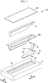
- FIG. 1 is an exploded perspective view illustrating the molding apparatus 100 according to the embodiment of the present disclosure.
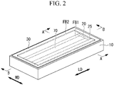
- FIG. 2 is a perspective view illustrating the molding apparatus 100 according to the embodiment of the present disclosure and illustrates a state in which fiber base materials FB1 and FB2 are placed in a first mold 10.
- FIG. 3 is a perspective view illustrating an example of a composite material 200 manufactured by the molding apparatus 100 illustrated in FIG. 1 .
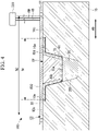
- FIG. 4 is an A-A arrow sectional view of the molding apparatus 100 illustrated in FIG. 2 .
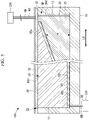
- FIG. 5 is a B-B arrow sectional view of the molding apparatus 100 illustrated in FIG. 2 .
- the molding apparatus 100 is an apparatus that executes infusion molding in which the fiber base material FB1 and the fiber base material FB2 disposed in the first mold 10 and a second mold 20, which are lower molds, are sealed in a tightly closed space CS using a bagging film 30 as an upper mold, the tightly closed space CS is filled with a resin material RM, and the resin material RM is cured through pressure reduction in the tightly closed space CS.
- the infusion molding is one of methods such as resin transfer molding (RTM) and resin infusion in which fiber base materials are impregnated with a resin using a pressure difference between a vacuum pressure and an atmospheric pressure.
- the molding apparatus 100 molds the composite material (fiber reinforced composite material) 200 illustrated in FIG. 3 in an example.
- the composite material 200 illustrated in FIG. 3 is a stringer used as a reinforcing material that reinforces an aircraft body.
- the composite material 200 is a member having a long shape extending in a longitudinal direction (first direction) LD and having a projecting center portion in a width direction WD.
- the width direction (second direction) WD is a direction that perpendicularly intersects the longitudinal direction LD in a plane in which the composite material 200 is placed.
- the composite material 200 is a member in which a first member 210 obtained by impregnating the fiber base material FB1 with a resin material and a second member 220 obtained by impregnating the fiber base material FB2 with a resin material are integrated and cured.
- the first member 210 includes a pair of flat portions 211 disposed on both end sides in the width direction WD and formed into a flat shape and a projecting portion 212 connected to the pair of flat portions 211 and having a projecting center portion in the width direction WD.
- the second member 220 is a member with a flat shape or with a predetermined curvature disposed in the longitudinal direction LD and the width direction WD.
- the fiber base material FB1 and the fiber base material FB2 are members obtained by laminating, in a plurality of layers, sheets formed of a reinforcing fiber material such as carbon fiber or glass fiber. Also, the fiber base material FB1 and the fiber base material FB2 may be prepregs partially impregnated with the resin material RM in advance.
- the resin material RM is a thermosetting resin material such as an epoxy resin, unsaturated polyester, vinyl ester, phenol, cyanate ester, or polyimide.
- thermoplastic resin examples include polyether ether ketone (PEEK), polyethylene terephthalate (PET), polybutylene terephthalate (PBT), nylon 6 (PA6), nylon 66 (PA66), polyphenylene sulfide (PPS), polyether imide (PEI), or polyether ketone ketone (PEKK) .
- PEEK polyether ether ketone
- PET polyethylene terephthalate
- PBT polybutylene terephthalate
- PA6 nylon 6
- PA66 nylon 66
- PPS polyphenylene sulfide
- PEI polyether imide
- PEKK polyether ketone ketone
- the composite material 200 illustrated in FIG. 3 includes a recessed portion CP defined by the flat portions 211 and the projecting portion 212 and extending in the longitudinal direction LD.
- the molding apparatus 100 uses a core portion 70 that is a core inserted into the recessed portion CP in order to mold the composite material 200 with the recessed portion CP. It is possible to maintain the shape of the recessed portion CP as a constant shape during molding of the composite material 200 by molding the composite material 200 in a state in which the core portion 70 is inserted into the recessed portion CP.
- the molding apparatus 100 includes the first mold 10, the second mold 20, a spacer 25, the bagging film (tightly closing member) 30, a suctioning line (suctioning portion) 40, a resin injection line (resin injecting portion) 50, a resin dispersing medium (sheet) 60, and the core portion 70.
- the first mold 10 is a mold in which the fiber base material FB1 is disposed to mold the fiber base material FB1 into a desired shape. As illustrated in FIGS. 1 and 4 , the first mold 10 is a female mold in which a pair of molding surfaces (first molding surfaces) 10a, a molding surface 10b, and a pair of molding surfaces (second molding surfaces) 10c are formed.
- the pair of molding surfaces 10a are molding surfaces, on which the fiber base material FB1 is disposed, which extend in the width direction WD.
- the molding surface 10b is a molding surface, on which the fiber base material FB1 is disposed, which has a shape recessed downward from the molding surfaces 10a.
- the pair of molding surfaces 10a are disposed at both ends of the molding surface 10b in the width direction WD.
- the molding surfaces 10a and the molding surface 10b are molding surfaces on which the fiber base material FB1 with a first width W1 in the width direction WD that perpendicularly intersects the longitudinal direction LD is disposed.
- the pair of molding surfaces 10c are molding surfaces, on which the fiber base material FB2 is disposed, which extend in the width direction WD.
- the fiber base material FB1 has the first width W1 in the width direction WD and is placed along the pair of molding surfaces 10a and the molding surface 10b.
- the fiber base material FB2 has the second width W2 that is wider than the first width W1 in the width direction WD and is placed along the pair of molding surfaces 10c.
- the first mold 10 accommodates the fiber base material FB1 in a region between a first end surface (first end portion) 11 and a second end surface (second end portion) 12 in the longitudinal direction LD.
- the second mold 20 is a mold disposed in the first mold 10 such that the second mold 20 is movable in the longitudinal direction LD for molding the end portion of the fiber base material FB1 in the longitudinal direction LD into a desired shape.
- the second mold 20 includes a molding surface 20a, a contact surface 20b, and a support portion 20c.
- the molding surface 20a is a surface for molding the fiber base material FB1 through contact with the end portion of the fiber base material FB1 in the longitudinal direction LD. As illustrated in FIG. 5 , the molding surface 20a is an inclined surface inclined such that a height H from a lower end gradually decreases from the second end surface 12 to the first end surface 11.
- the contact surface 20b is a surface that is brought into contact with the molding surface 10b of the first mold 10 in a state in which the second mold 20 is disposed in the first mold 10. As illustrated in FIG. 4 , the contact surface 20b has a shape corresponding to the molding surface 10b in the width direction WD. Therefore, the entire region of the contact surface 20b is brought into contact with the molding surface 10b of the first mold 10 in the state in which the second mold 20 is disposed in the first mold 10.
- the support portion 20c is a member disposed to extend in the width direction WD in the state in which the second mold 20 is disposed in the first mold 10.
- the support portion 20c has both end portions in the width direction WD supported by the pair of molding surfaces 10a of the first mold 10 in the state in which the second mold 20 is disposed in the first mold 10.
- the support portion 20c is disposed on the pair of molding surfaces 10a, it is possible to smoothly mold the end surface of the fiber base material FB1 by causing the support portion 20c to move in the longitudinal direction LD and pressing the support portion 20c against the end surface of the fiber base material FB1 in the longitudinal direction LD.
- the entire second mold 20 including a part that is brought into contact with the fiber base material FB1 via a resin dispersing medium 60 is formed of a metal material such as aluminum alloy, another aspect is also conceivable.
- a part of the second mold 20 that is brought into contact with the fiber base material FB1 via the resin dispersing medium 60 may be formed of a member with a thermal expansion property or stretchability (for example, silicone or foamed silicone).
- the second mold 20 it is possible to cause the second mold 20 to stretch to follow a change in shape of the fiber base material FB1 even in a case in which the shape of the fiber base material FB1 changes due to compression or thermal expansion in the injection process of injecting the resin material RM into the tightly closed space CS, the following curing process, or the like, by forming the part of the second mold 20 that is brought into contact with the fiber base material FB1 using a member with stretchability.
- the part of the second mold 20 that is brought into contact with the fiber base material FB1 via the resin dispersing medium 60 may be a member with stretchability, while the other part may be formed of a metal material.
- the entire second mold 20 including the part that is brought into contact with the fiber base material FB1 via the resin dispersing medium 60 may be formed of a member with stretchability.
- the spacer 25 is a plate-shaped member that is inserted into a gap GP formed between an end surface 20d of the second mold 20 and the second end surface 12 of the first mold 10 as illustrated in FIG. 5 .
- the gap GP is formed between the end surface 20d of the second mold 20 and the second end surface 12 of the first mold 10 in a state in which the fiber base material FB1 is in contact with the first end surface 11 of the first mold 10 in the longitudinal direction LD and the second mold 20 is in contact with the fiber base material FB1.
- the gap GP formed between the end surface 20d of the second mold 20 and the second end surface 12 of the first mold 10 has an arbitrary interval in accordance with an individual difference of the fiber base material FB1 or an individual difference of the first mold 10.
- the spacer 25 is required to appropriately adjust the gap GP regardless of the thickness (the length in the longitudinal direction LD) of the gap GP formed. Specifically, it is necessary to adjust the gap GP such that a predetermined interval is formed in consideration of thermal expansion or the like caused by heating the resin material RM in the curing process, which will be described later.
- a plurality of types of spacers 25 with mutually different thicknesses are prepared, and a spacer 25 with a length in the longitudinal direction LD in accordance with the gap GP is selected such that the gap GP has a predetermined interval and is then inserted into the gap GP.
- a plurality of plate materials with specific thicknesses that are sufficiently thinner than the thickness of the gap GP that is typically formed may be prepared as the spacers 25.
- a plurality of spacers 25 with specific thicknesses are combined such that the thickness thereof conforms to the thickness of the gap GP to achieve the thickness that conforms to the gap GP, and the plurality of spacers 25 are inserted into the gap GP.
- the bagging film 30 is a member that seals the fiber base material FB1 and the fiber base material FB2 in the first mold 10 and forms the tightly closed space CS.
- the bagging film 30 is formed of a resin material containing nylon as a main constituent, for example.
- the bagging film 30 is bonded to the first mold 10 with a sealant tape SP to cover the entire periphery of the molding surfaces 10a, the molding surface 10b, and the molding surfaces 10c of the first mold 10.
- the suctioning line 40 is a pipe body having one end connected to a suctioning source 320 such as a vacuum pump and the other end connected to the tightly closed space CS as illustrated in FIGS. 4 and 5 .
- the suctioning line 40 can discharge air that is present in the tightly closed space CS from the tightly closed space CS and reduce the pressure in the tightly closed space CS to a pressure (for example, a vacuum pressure) that is lower than an atmospheric pressure through connection between the suctioning source 320 and the tightly closed space CS.
- the resin injection line 50 is a pipe body for injecting the resin material RM to the fiber base material FB1 sealed in the tightly closed space CS, the pressure in which has been reduced by the suctioning line 40, as illustrated in FIG. 5 .
- the resin injection line 50 has one end connected to a supply source 330 that supplies the resin material RM and the other end connected to the tightly closed space CS.
- the resin injection line 50 can supply the resin material RM from the supply source 330 to the tightly closed space CS, the pressure in which has been reduced by the suctioning line 40, through connection between the supply source 330 and the tightly closed space CS.
- the resin dispersing medium 60 is a sheet-shaped medium for supplying the resin material RM supplied from the resin injection line 50 to the tightly closed space CS while dispersing the resin material RM to the entire fiber base material FB1.
- the resin dispersing medium 60 has an net-shaped internal structure that is a structure in which the resin material RM can pass therethrough, for example. Therefore, the resin material RM supplied to the tightly closed space CS, the pressure in which has been reduced by the suctioning line 40, passes through the inside of the resin dispersing medium 60 and is dispersed to the entire surface of the fiber base material FB1, and the fiber base material FB1 is then impregnated with the resin material RM.
- the resin dispersing medium 60 is a sheet formed of nylon or polyester, for example, and having releasability from the fiber base material FB1. Since the resin dispersing medium 60 has releasability, it is possible to easily remove the resin dispersing medium 60 from the fiber base material FB1 after the molding of the composite material 200 is completed.
- the resin dispersing medium 60 may not be disposed between the fiber base material FB1 and the first mold 10.
- groove portions that promote dispersion of the resin material RM may be formed in the molding surfaces 10a, the molding surface 10b, and the molding surfaces 10c of the first mold 10.
- the core portion 70 is a member disposed in a state in which the core portion 70 is in contact with the fiber base material FB1 disposed in the first mold 10 with no gap.
- the core portion 70 is a member having a shape corresponding to the recessed portion CP and formed into a long shape in the longitudinal direction LD.
- the core portion 70 is a member with hardness with which a constant shape can be held even in a case in which the tightly closed space CS is brought into a vacuum state.
- the core portion 70 is formed of a foam material such as polyethylene, polypropylene, polyvinyl chloride, polymethacrylimide, balsa wood, or a carbon foam body.
- the core portion 70 may be a hollow member made of rubber such as bladder formed using a material, to which an inner pressure due to an atmospheric pressure is applied during molding, which is vacuum-suctioned to shrink such that the material can be pulled out after the molding.
- FIG. 6 is a flowchart illustrating the composite material molding method according to the present embodiment.
- Step S101 shape
- the fiber base material FB1 formed into a flat shape is shaped with a shaping mold (not illustrated) to obtain a shape corresponding to the molding surfaces 10a and the molding surface 10b of the first mold 10.
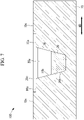
- Step S102 the second mold 20 is disposed in the first mold 10 such that the contact surface 20b is brought into contact with the molding surface 10b. If the second mold 20 is disposed in the first mold 10, then the state illustrated in FIG. 7 is achieved.
- FIG. 7 is an A-A arrow sectional view of the molding apparatus 100 illustrated in FIG. 2 and illustrates the state in which the second mold 20 is disposed in the first mold 10.
- Step S103 the fiber base material FB1 is placed on the molding surfaces 10a and the molding surface 10b of the first mold 10 in which the second mold 20 is disposed.
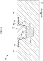
- the resin dispersing medium 60 is disposed between the fiber base material FB1 and the first mold 10. If the fiber base material FB1 is placed in the first mold 10, then the state illustrated in FIG. 8 is achieved.
- FIG. 8 is an A-A arrow sectional view of the molding apparatus 100 illustrated in FIG. 2 and illustrates the state in which the fiber base material FB1 is placed in the first mold 10.
- Step S104 the gap GP formed between the second mold 20 and the second end surface 12 of the first mold 10 is measured in a state in which the fiber base material FB1 is in contact with the first end surface 11 of the first mold 10 in the longitudinal direction LD and the second mold 20 is in contact with the fiber base material FB1.
- Step S104 an operator grips the support portion 20c of the second mold 20, causes the second mold 20 to move in the longitudinal direction LD toward the first end surface 11, and achieves the state illustrated in FIG. 9.
- FIG. 9 is a B-B arrow sectional view of the molding apparatus 100 illustrated in FIG. 2 and illustrates a state in which the second mold 20 is in contact with the fiber base material FB1.
- the gap GP is formed between the end surface 20d of the second mold 20 and the second end surface 12 of the first mold 10. The operator measures the length of the gap GP in the longitudinal direction LD using a measurement instrument (not illustrated).
- the gap GP formed between the second mold 20 and the second end surface 12 of the first mold 10 is directly measured in the state in which the fiber base material FB1 is in contact with the first end surface 11 of the first mold 10 in the longitudinal direction LD and the second mold 20 is in contact with the fiber base material FB1 in the above description, another aspect is also conceivable.
- the length corresponding to the gap GP may be indirectly measured in a state in which the end surface 20d of the second mold 20 is brought into contact with the second end surface 12 of the first mold 10.
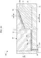
- FIG. 10 is a diagram illustrating a state in which a portion between the second mold 20 and the fiber base material FB1 is filled with a filling material FL with the end surface 20d of the second mold 20 and the second end surface 12 of the first mold 10 in contact with each other.
- the filling material FL is a material that is deformed through an application of a predetermined force and can hold the shape after the deformation, such as a clay or a curable resin.
- the portion between the second mold 20 and the fiber base material FB1 is filled with the filling material FL little by little in a state in which the end surface 20d of the second mold 20 and the second end surface 12 of the first mold 10 are brought into contact with each other, and a state in which the fiber base material FB1 is in contact with the first end surface 11 of the first mold 10, the end surface 20d of the second mold 20 and the second end surface 12 of the first mold 10 are in contact with each other, and the portion between the second mold 20 and the fiber base material FB1 is filled with the filling material FL is achieved.
- the fiber base material FB1 is removed from the first mold 10, and a length L1 of the filling material FL in the longitudinal direction LD is measured using a measurement instrument (not illustrated).
- the length L1 measured using the measurement instrument is the same as the length of the gap GP in the longitudinal direction LD illustrated in FIG. 9 . Therefore, it is possible to indirectly measure the length corresponding to the gap GP through the measurement of the length L1.
- Step S105 the spacer 25 with the length in the longitudinal direction LD in accordance with the gap GP measured in the measurement process (S104) is inserted between the end surface 20d of the second mold 20 and the second end surface 12 of the first mold 10.
- the state illustrated in FIG. 5 is achieved by the insertion of the spacer 25 into the gap GP.
- a state in which a predetermined interval is formed between the fiber base material FB1 and the spacer 25 in consideration of thermal expansion due to heating of the resin material RM in the curing process that will be described later is achieved.
- Step S106 second placing process
- the fiber base material FB2 is placed on the molding surfaces 10c of the first mold 10 in which the fiber base material FB1 has been placed.
- Step S107 the fiber base material FB1 and the fiber base material FB2 are sealed in the first mold 10, and the tightly closed space CS is formed. Specifically, the bagging film 30 is bonded to the first mold 10 with the sealant tape ST to cover the entire periphery of the first mold 10, and the tightly closed space CS is formed. If the tightly closing process in Step S107 is completed, the state illustrated in FIGS. 4 and 5 is achieved.
- Step S107 If the tightly closed space CS is formed in Step S107 (tightly closing process), then a state in which the resin injection line 50 connected to the supply source 330 for the resin material RM and the tightly closed space CS communicate with each other is achieved. Also, if the tightly closed space CS is formed, a state in which the suctioning line 40 connected to the suctioning source 320 and the tightly closed space CS communicate with each other is achieved.
- Step S108 injection process
- air in the tightly closed space CS formed in Step S107 is suctioned to reduce the pressure in the tightly closed space CS
- the resin material RM is injected to the fiber base material FB1 and the fiber base material FB2 sealed in the tightly closed space CS.
- the suctioning source 320 is caused to operate, the air that is present in the tightly closed space CS is discharged from the tightly closed space CS via the suctioning line 40, and the pressure in the tightly closed space CS is reduced to a pressure in a vacuum state or substantially in a vacuum state that is lower than the atmospheric pressure.
- the supply source 330 is brought into a state in which the supply source 330 can supply the resin material RM to the resin injection line 50, and the resin material RM is injected into the tightly closed space CS using a pressure difference in the resin injection line 50 and in the tightly closed space CS, the pressure in which has been reduced.
- the resin material RM passes through the inside of the resin dispersing medium 60, is dispersed to the entire surface of the fiber base material FB1, and is then injected to the fiber base material FB1 and the fiber base material FB2.
- a part of the resin material RM with which the fiber base material FB1 and the fiber base material FB2 are impregnated passes through the fiber base material FB2, is guided to the suctioning line 40, and is discharged as an extra resin material RM to the suctioning line 40.
- Step S108 injection process
- the pressure in the tightly closed space CS is reduced to a pressure in a vacuum state or substantially in a vacuum state, and the fiber base material FB1 and the resin material RM with which the fiber base material FB1 has been impregnated are thus pressurized by the atmospheric pressure.
- Step S109 the thermosetting resin material RM injected to the fiber base material FB1 and the fiber base material FB2 in Step S108 (injection process) is heated to a thermosetting temperature or higher using a heating portion (not illustrated), thereby curing the resin material RM.
- Step S109 the heating achieved by the heating portion is not performed in Step S109 (curing process).
- the resin material RM is cooled such that the temperature of the resin material RM becomes sufficiently lower than a softening temperature.
- Step S110 removing process
- the composite material 200 including the resin material RM, the fiber base material FB1, and the fiber base material FB2 cured in Step S109 (curing process) is removed from the first mold 10.
- the sealant tape ST for bonding the bagging film 30 and the first mold 10 is detached, and the bagging film 30 is removed from the first mold 10.
- the composite material 200 with the core portion 70 inserted into the recessed portion CP is removed from the first mold from which the bagging film 30 has been removed. Moreover, the core portion 70 is detached from the recessed portion CP of the composite material 200. Through the aforementioned processes, the manufacturing process of the composite material 200 molded with the first mold 10 and the second mold 20 is ended.
- the gap GP formed between the end surface 20d of the second mold 20 and the second end surface 12 of the first mold 10 is measured in the measurement process (S104) in the state in which the fiber base material FB1 is in contact with the first end surface 11 of the first mold 10 in the longitudinal direction LD and the molding surface 20a of the second mold 20 is in contact with the fiber base material FB1.
- the gap GP is formed due to manufacturing errors or the like of the first mold 10 and the fiber base material FB1.
- the composite material 200 is molded by injecting the resin material RM to the fiber base material FB1 in a state in which the gap GP does not have an appropriate interval, a part including only the resin material RM is formed in the second end surface 12 of the fiber base material FB1 in the longitudinal direction LD.
- the spacer 25 with a length in the longitudinal direction LD in accordance with the measured gap GP is inserted between the end surface 20d of the second mold 20 and the second end surface 12 of the first mold 10 in the insertion process (S105). Since the gap GP is adjusted to have an appropriate interval through the insertion of the spacer 25 into the gap GP, the resin material RM is injected into the tightly closed space CS in a state in which an appropriate interval is formed between the end surface 20d of the second mold 20 and the second end surface 12 of the first mold 10. It is thus possible to curb formation of a part including only the resin material RM in the second end surface 12 of the fiber base material FB1 in the longitudinal direction LD in the composite material.
- the second mold 20 it is possible to cause the second mold 20 to stretch to follow a change in shape of the fiber base material FB1 even in a case in which the shape of the fiber base material FB1 changes in the injection process (S108) or the following curing process (S109), by forming the part of the second mold 20 that is brought into contact with the fiber base material FB1 using a member with stretchability. Therefore, it is possible to prevent the gap GP that does not have an appropriate interval from being formed between the end surface 20d of the second mold 20 and the second end surface 12 of the first mold 10 in the injection process (S108) and the following curing process (S109).
- the molding apparatus 100 is adapted such that the spacer 25 is inserted into the gap GP in the longitudinal direction LD in consideration of an individual difference of the fiber base material FB1 or an individual difference of the first mold 10 in the longitudinal direction LD in the above description, an individual difference of the fiber base material FB1 or an individual difference of the first mold 10 in the width direction WD may be further taken into consideration.
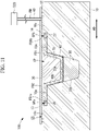
- FIG. 11 is a sectional view illustrating a modification of the molding apparatus 100 and is an A-A arrow sectional view of the molding apparatus illustrated in FIG. 2 .
- a gap GPa is formed between an end surface FBla of the fiber base material FB1 and a third end surface 13 of the first mold 10 in the width direction WD.
- a gap GPb is formed between an end surface FBlb of the fiber base material FB1 and a fourth end surface 14 of the first mold 10 in the width direction WD.
- the gap GPa and the gap GPb have arbitrary intervals in accordance with an individual difference of the fiber base material FB1 or an individual difference of the first mold 10.
- a spacer 26 and a spacer 27 are inserted in order to adjust each of the gap GPa and the gap GPb to have an appropriate interval.
- the gap GPa and the gap GPb are adjusted to have appropriate intervals for the purpose of forming intervals in consideration of thermal expansion and the like due to heating of the resin material RM in the curing process.
- the spacer 26 is a member extending in a rod shape in the longitudinal direction LD and has a length in the width direction WD in accordance with the gap GPa.
- the spacer 27 is a member extending in a rod shape in the longitudinal direction LD and has a length in the width direction WD in accordance with the gap GPb.
- a plurality of types of spacers 26 with mutually different lengths in the width direction WD are prepared, and a spacer 26 with a length in accordance with the gap GPa is selected and inserted into the gap GPa such that the gap GPa has a predetermined interval.
- a plurality of types of spacers 27 with mutually different lengths in the width direction WD are prepared, and a spacer 27 with a length in accordance with the gap GPb is selected and inserted into the gap GPb such that the gap GPb has a predetermined interval.
- the gap GPa and the gap GPb are measured in Step S104 (measurement process) described above. Also, the spacer 26 and the spacer 27 are inserted into the gap GPa and the gap GPb, respectively, in Step S105 (insertion process) described above.
- the resin injection line 50 is provided below the first mold 10 and the suctioning line 40 is provided above the first mold 10 in the above description, another aspect is also conceivable.
- the resin injection line 50 may be provided above the first mold 10, and the suctioning line 40 may be provided below the first mold 10.
- the resin material RM is injected from the resin injection line 50 into the tightly closed space CS through pressure reduction in the tightly closed space CS in the above description, another aspect is also conceivable.
- the resin material RM may be injected from the resin injection line 50 into the tightly closed space CS by the supply source 330 pressurizing the resin material RM and pressing the resin material RM out to the resin injection line 50.
- the fiber reinforced composite material molding method described in the embodiments described above is recognized as follows, for example.
- the fiber reinforced composite material molding method is a fiber reinforced composite material molding method for molding a composite material (200) with a first mold (10) and a second mold (20), the first mold including molding surface (10b) extending in a first direction (LD), the second mold being disposed in the first mold such that the second mold is movable in the first direction and including a contact surface (20b) that is brought into contact with the molding surface, the method including: a disposing process (S012) of disposing the second mold in the first mold such that the contact surface is brought into contact with the molding surface; a first placing process (S103) of placing a fiber base material (FB1) on the molding surface of the first mold in which the second mold is disposed; a measurement process (S104) of measuring a gap (GP) formed between the second mold and a second end portion (12) of the first mold in a state in which the fiber base material is in contact with a first end portion (11) of the first mold in the first direction and the second mold is in contact with the fiber base material; an a disposing process
- the gap formed between the end surface of the second mold and the second end surface of the first mold is measured in the measurement process in the state in which the fiber base material is in contact with the first end surface of the first mold in the first direction and the molding surface of the second mold is in contact with the fiber base material.
- the gap is formed due to manufacturing errors or the like of the first mold and the fiber base material. If the composite material is molded by injecting the resin material to the fiber base material in a state in which the gap does not have an appropriate interval, a part including only the resin material is formed in the second end surface of the fiber base material in the first direction.
- the spacer with a length in the first direction in accordance with the measured gap is inserted between the second mold and the second end portion of the first mold in the insertion process in the fiber reinforced composite material molding method according to the present disclosure. Since the gap is adjusted to have an appropriate interval through the insertion of the spacer into the gap, the resin material is injected into the tightly closed space in a state in which an appropriate interval is formed between the second mold and the second end portion of the first mold. Therefore, it is possible to curb formation of the part including only the resin material at the second end portion of the fiber base material in the first direction in the composite material.
- the fiber reinforced composite material molding method is preferably configured such that the molding surface of the first mold includes a first molding surface on which a first fiber base material included in the fiber base material with a first width in a second direction that perpendicularly intersects the first direction is disposed and a second molding surface on which a second fiber base material included in the fiber base material with a second width that is wider than the first width in the second direction is disposed, and the method further includes: a second placing process of placing the second fiber base material on the second molding surface, in addition to the disposition of the first fiber base material on the first molding surface.
- the composite material molding method in the above configuration it is possible to form the composite material in which the first fiber base material and the second fiber base material are integrated with each other by placing the first fiber base material with the first width on the first molding surface of the first mold and placing the second fiber base material with the second width that is wider than the first width on the second molding surface of the first mold.
- the fiber reinforced composite material molding method according to the present disclosure is preferably configured such that at least a part of the second mold that comes into contact with the fiber base material is formed of a member with stretchability.
- the fiber reinforced composite material molding apparatus described in the embodiments described above is recognized as follows, for example.
- the fiber reinforced composite material molding apparatus includes: a first mold that includes a molding surface, which extends in a first direction, on which a fiber base material is placed; a second mold that is disposed in the first mold such that the second mold is movable in the first direction, the second mold including a contact surface that is brought into contact with the molding surface; a spacer that is inserted into a gap formed between the second mold and a second end portion of the first mold in a state in which the fiber base material is in contact with a first end portion of the first mold in the first direction and the second mold is in contact with the fiber base material, the spacer having a length in the first direction in accordance with the gap; a tightly closing member that seals the fiber base material in the first mold and forms a tightly closed space; and a resin injecting portion that injects a resin material to the fiber base material sealed in the tightly closed space.
- the gap formed between the end surface of the second mold and the second end surface of the first mold is measured in the measurement process in the state in which the fiber base material is in contact with the first end surface of the first mold in the first direction and the molding surface of the second mold is in contact with the fiber base material.
- the gap is formed due to manufacturing errors or the like of the first mold and the fiber base material. If the composite material is molded by injecting the resin material to the fiber base material in a state in which the gap does not have an appropriate interval, a part including only the resin material is formed in the second end surface of the fiber base material in the first direction.
- the spacer with the length in the first direction in accordance with the gap formed between the second mold and the second end portion of the first mold is inserted. Since the gap is adjusted to have an appropriate interval through the insertion of the spacer into the gap, the resin material is injected into the tightly closed space in a state in which an appropriate interval is formed between the second mold and the second end portion of the first mold. It is thus possible to curb formation of the part including only the resin material at the second end portion of the fiber base material in the first direction in the composite material.
- the fiber reinforced composite material molding apparatus is preferably configured such that the molding surface of the first mold includes a first molding surface on which a first fiber base material included in the fiber base material with a first width in a second direction that perpendicularly intersects the first direction is disposed and a second molding surface on which a second fiber base material included in the fiber base material with a second width that is wider than the first width in the second direction is disposed.
- the composite material molding apparatus in the above configuration it is possible to form the composite material in which the first fiber base material and the second fiber base material are integrated with each other by placing the first fiber base material with the first width on the first molding surface of the first mold and placing the second fiber base material with the second width that is wider than the first width on the second molding surface of the first mold.
- the fiber reinforced composite material molding apparatus is preferably configured such that at least a part of the second mold that comes into contact with the fiber base material is formed of a member with stretchability.
- the second mold it is possible to cause the second mold to stretch to follow a change in shape of the fiber base material even in a case in which the shape of the fiber base material changes after the resin material is injected into the tightly closed space, by forming the part of the second mold that comes into contact with the fiber base material using the member with stretchability. It is thus possible to prevent a gap that does not have an appropriate interval from being formed between the second mold and the second end portion of the first mold after the resin material is injected into the tightly closed space.
Landscapes
- Engineering & Computer Science (AREA)
- Mechanical Engineering (AREA)
- Chemical & Material Sciences (AREA)
- Composite Materials (AREA)
- Casting Or Compression Moulding Of Plastics Or The Like (AREA)
- Moulds For Moulding Plastics Or The Like (AREA)
- Moulding By Coating Moulds (AREA)
Abstract
Description
- The present disclosure relates to a fiber reinforced composite material molding method and a fiber reinforced composite material molding apparatus.
- In the related art, a molding apparatus for molding a fiber reinforced composite material such as fiber reinforced plastic of resin reinforced with a fiber base material such as glass fiber or a carbon fiber is known (see the Publication of
Japanese Patent No. 6216134 Japanese Patent No. 6216134 Japanese Patent No. 6216134 - However, in a case in which resin transfer molding (RTM) of impregnating the fiber base material with the resin material using a pressure difference between a vacuum pressure and an atmospheric pressure is applied, there is a probability that an appropriate composite material cannot be molded merely by a method of adjusting the clearance in the plate thickness direction of the fiber base material. In a case in which a clearance is generated between the die and the molding jig at an end portion of the fiber base material, for example, the resin material injected into the clearance is solidified, and a part (resin rich part) including only the resin material is formed.
- If the part including only the resin material is formed, it is necessary to perform an operation of appropriately removing the part including only the resin material after the composite material is molded, which leads to an increase in manufacturing cost of the composite material. Also, the part including only the resin material does not include the fiber base material and thus easily cracks, and if cracking occurs in the part, there is a probability that a damage occurs even in another part of the composite material including the fiber base material.
- The present disclosure has been made in view of such circumstances, and an object thereof is to provide a fiber reinforced composite material molding method and a fiber reinforced composite material molding apparatus capable of curbing formation of a part including only a resin material at an end portion of a fiber base material in a composite material and preventing an increase in manufacturing cost of the composite material and occurrence of any damage.
- A fiber reinforced composite material molding method according to an aspect of the present disclosure is a fiber reinforced composite material molding method for molding a composite material with a first mold and a second mold, the first mold including a molding surface extending in a first direction, the second mold being disposed in the first mold such that the second mold is movable in the first direction and including a contact surface that is brought into contact with the molding surface, the method including: a disposing process of disposing the second mold in the first mold such that the contact surface is brought into contact with the molding surface; a first placing process of placing a fiber base material on the molding surface of the first mold in which the second mold is disposed; a measurement process of measuring a gap formed between the second mold and a second end portion of the first mold in a state in which the fiber base material is in contact with a first end portion of the first mold in the first direction and the second mold is in contact with the fiber base material; an insertion process of inserting, between the second mold and the second end portion of the first mold, a spacer with a length in the first direction in accordance with the gap measured in the measurement process; a tightly closing process of sealing the fiber base material in the first mold with a tightly closing member and forming a tightly closed space; and an injection process of injecting a resin material into the tightly closed space formed in the tightly closing process.
- A fiber reinforced composite material molding apparatus according to an aspect of the present disclosure is a fiber reinforced composite material molding apparatus including a first mold that includes a molding surface, which extends in a first direction, on which a fiber base material is placed; a second mold that is disposed in the first mold such that the second mold is movable in the first direction, the second mold including a contact surface that is brought into contact with the molding surface; a spacer that is inserted into a gap formed between the second mold and a second end portion of the first mold in a state in which the fiber base material is in contact with a first end portion of the first mold in the first direction and the second mold is in contact with the fiber base material, the spacer having a length in the first direction in accordance with the gap; a tightly closing member that seals the fiber base material in the first mold and forms a tightly closed space; and a resin injecting portion that injects a resin material to the fiber base material sealed in the tightly closed space.
- According to the present disclosure, it is possible to provide a fiber reinforced composite material molding method and a fiber reinforced composite material molding apparatus capable of curbing formation of a part including only a resin material at an end portion of a fiber base material in a composite material and preventing an increase in manufacturing cost of the composite material and occurrence of any damage.
-
-
FIG. 1 is an exploded perspective view illustrating the molding apparatus according to the embodiment of the present disclosure. -
FIG. 2 is a perspective view illustrating the molding apparatus according to the embodiment of the present disclosure and illustrates a state in which fiber base materials are placed in a first mold. -
FIG. 3 is a perspective view illustrating an example of a composite material manufactured by the molding apparatus illustrated inFIG. 1 . -
FIG. 4 is an A-A arrow sectional view of the molding apparatus illustrated inFIG. 2 . -
FIG. 5 is a B-B arrow sectional view of the molding apparatus illustrated inFIG. 2 . -
FIG. 6 is a flowchart illustrating the composite material molding method according to the present embodiment. -
FIG. 7 is an A-A arrow sectional view of the molding apparatus illustrated inFIG. 2 and illustrates the state in which the second mold is disposed in the first mold. -
FIG. 8 is an A-A arrow sectional view of the molding apparatus illustrated inFIG. 2 and illustrates the state in which the fiber base material is placed in the first mold. -
FIG. 9 is a B-B arrow sectional view of the molding apparatus illustrated inFIG. 2 and illustrates a state in which the second mold is in contact with the fiber base material. -
FIG. 10 is a diagram illustrating a state in which a portion between the second mold and the fiber base material is filled with a filling material with the end surface of the second mold and the second end surface of the first mold in contact with each other. -
FIG. 11 is a sectional view illustrating a modification of the molding apparatus. - Hereinafter, a molding apparatus (fiber reinforced composite material molding apparatus) 100 and a fiber reinforced composite material molding method using the same according to an embodiment of the present disclosure will be described with reference to the drawings.
FIG. 1 is an exploded perspective view illustrating themolding apparatus 100 according to the embodiment of the present disclosure.FIG. 2 is a perspective view illustrating themolding apparatus 100 according to the embodiment of the present disclosure and illustrates a state in which fiber base materials FB1 and FB2 are placed in afirst mold 10. -
FIG. 3 is a perspective view illustrating an example of acomposite material 200 manufactured by themolding apparatus 100 illustrated inFIG. 1 .FIG. 4 is an A-A arrow sectional view of themolding apparatus 100 illustrated inFIG. 2 .FIG. 5 is a B-B arrow sectional view of themolding apparatus 100 illustrated inFIG. 2 . - The
molding apparatus 100 according to the present embodiment is an apparatus that executes infusion molding in which the fiber base material FB1 and the fiber base material FB2 disposed in thefirst mold 10 and asecond mold 20, which are lower molds, are sealed in a tightly closed space CS using abagging film 30 as an upper mold, the tightly closed space CS is filled with a resin material RM, and the resin material RM is cured through pressure reduction in the tightly closed space CS. The infusion molding is one of methods such as resin transfer molding (RTM) and resin infusion in which fiber base materials are impregnated with a resin using a pressure difference between a vacuum pressure and an atmospheric pressure. - The
molding apparatus 100 according to the present embodiment molds the composite material (fiber reinforced composite material) 200 illustrated inFIG. 3 in an example. Thecomposite material 200 illustrated inFIG. 3 is a stringer used as a reinforcing material that reinforces an aircraft body. Thecomposite material 200 is a member having a long shape extending in a longitudinal direction (first direction) LD and having a projecting center portion in a width direction WD. The width direction (second direction) WD is a direction that perpendicularly intersects the longitudinal direction LD in a plane in which thecomposite material 200 is placed. - As illustrated in
FIG. 3 , thecomposite material 200 is a member in which afirst member 210 obtained by impregnating the fiber base material FB1 with a resin material and asecond member 220 obtained by impregnating the fiber base material FB2 with a resin material are integrated and cured. Thefirst member 210 includes a pair offlat portions 211 disposed on both end sides in the width direction WD and formed into a flat shape and a projectingportion 212 connected to the pair offlat portions 211 and having a projecting center portion in the width direction WD. Thesecond member 220 is a member with a flat shape or with a predetermined curvature disposed in the longitudinal direction LD and the width direction WD. - The fiber base material FB1 and the fiber base material FB2 are members obtained by laminating, in a plurality of layers, sheets formed of a reinforcing fiber material such as carbon fiber or glass fiber. Also, the fiber base material FB1 and the fiber base material FB2 may be prepregs partially impregnated with the resin material RM in advance. The resin material RM is a thermosetting resin material such as an epoxy resin, unsaturated polyester, vinyl ester, phenol, cyanate ester, or polyimide.
- Although the resin material RM is assumed to be a thermosetting resin material in the following description, a thermoplastic resin, for example, may be used. Examples of the thermoplastic resin include polyether ether ketone (PEEK), polyethylene terephthalate (PET), polybutylene terephthalate (PBT), nylon 6 (PA6), nylon 66 (PA66), polyphenylene sulfide (PPS), polyether imide (PEI), or polyether ketone ketone (PEKK) .
- The
composite material 200 illustrated inFIG. 3 includes a recessed portion CP defined by theflat portions 211 and the projectingportion 212 and extending in the longitudinal direction LD. Themolding apparatus 100 according to the present embodiment uses acore portion 70 that is a core inserted into the recessed portion CP in order to mold thecomposite material 200 with the recessed portion CP. It is possible to maintain the shape of the recessed portion CP as a constant shape during molding of thecomposite material 200 by molding thecomposite material 200 in a state in which thecore portion 70 is inserted into the recessed portion CP. - As illustrated in
FIGS. 1 and2 , themolding apparatus 100 according to the present embodiment includes thefirst mold 10, thesecond mold 20, aspacer 25, the bagging film (tightly closing member) 30, a suctioning line (suctioning portion) 40, a resin injection line (resin injecting portion) 50, a resin dispersing medium (sheet) 60, and thecore portion 70. - The
first mold 10 is a mold in which the fiber base material FB1 is disposed to mold the fiber base material FB1 into a desired shape. As illustrated inFIGS. 1 and4 , thefirst mold 10 is a female mold in which a pair of molding surfaces (first molding surfaces) 10a, amolding surface 10b, and a pair of molding surfaces (second molding surfaces) 10c are formed. - The pair of
molding surfaces 10a are molding surfaces, on which the fiber base material FB1 is disposed, which extend in the width direction WD. Themolding surface 10b is a molding surface, on which the fiber base material FB1 is disposed, which has a shape recessed downward from themolding surfaces 10a. The pair ofmolding surfaces 10a are disposed at both ends of themolding surface 10b in the width direction WD.
Themolding surfaces 10a and themolding surface 10b are molding surfaces on which the fiber base material FB1 with a first width W1 in the width direction WD that perpendicularly intersects the longitudinal direction LD is disposed. The pair ofmolding surfaces 10c are molding surfaces, on which the fiber base material FB2 is disposed, which extend in the width direction WD. - As illustrated in
FIG. 4 , the fiber base material FB1 has the first width W1 in the width direction WD and is placed along the pair ofmolding surfaces 10a and themolding surface 10b. The fiber base material FB2 has the second width W2 that is wider than the first width W1 in the width direction WD and is placed along the pair ofmolding surfaces 10c. As illustrated inFIG. 5 , thefirst mold 10 accommodates the fiber base material FB1 in a region between a first end surface (first end portion) 11 and a second end surface (second end portion) 12 in the longitudinal direction LD. - The
second mold 20 is a mold disposed in thefirst mold 10 such that thesecond mold 20 is movable in the longitudinal direction LD for molding the end portion of the fiber base material FB1 in the longitudinal direction LD into a desired shape. As illustrated inFIG. 1 , thesecond mold 20 includes amolding surface 20a, acontact surface 20b, and asupport portion 20c. - The
molding surface 20a is a surface for molding the fiber base material FB1 through contact with the end portion of the fiber base material FB1 in the longitudinal direction LD. As illustrated inFIG. 5 , themolding surface 20a is an inclined surface inclined such that a height H from a lower end gradually decreases from thesecond end surface 12 to thefirst end surface 11. - The
contact surface 20b is a surface that is brought into contact with themolding surface 10b of thefirst mold 10 in a state in which thesecond mold 20 is disposed in thefirst mold 10. As illustrated inFIG. 4 , thecontact surface 20b has a shape corresponding to themolding surface 10b in the width direction WD. Therefore, the entire region of thecontact surface 20b is brought into contact with themolding surface 10b of thefirst mold 10 in the state in which thesecond mold 20 is disposed in thefirst mold 10. - The
support portion 20c is a member disposed to extend in the width direction WD in the state in which thesecond mold 20 is disposed in thefirst mold 10. Thesupport portion 20c has both end portions in the width direction WD supported by the pair ofmolding surfaces 10a of thefirst mold 10 in the state in which thesecond mold 20 is disposed in thefirst mold 10. - Since the
support portion 20c is disposed on the pair ofmolding surfaces 10a, it is possible to smoothly mold the end surface of the fiber base material FB1 by causing thesupport portion 20c to move in the longitudinal direction LD and pressing thesupport portion 20c against the end surface of the fiber base material FB1 in the longitudinal direction LD. - Although the entire
second mold 20 including a part that is brought into contact with the fiber base material FB1 via aresin dispersing medium 60 is formed of a metal material such as aluminum alloy, another aspect is also conceivable. For example, a part of thesecond mold 20 that is brought into contact with the fiber base material FB1 via theresin dispersing medium 60 may be formed of a member with a thermal expansion property or stretchability (for example, silicone or foamed silicone). - It is possible to cause the
second mold 20 to stretch to follow a change in shape of the fiber base material FB1 even in a case in which the shape of the fiber base material FB1 changes due to compression or thermal expansion in the injection process of injecting the resin material RM into the tightly closed space CS, the following curing process, or the like, by forming the part of thesecond mold 20 that is brought into contact with the fiber base material FB1 using a member with stretchability. - Note that only the part of the
second mold 20 that is brought into contact with the fiber base material FB1 via theresin dispersing medium 60 may be a member with stretchability, while the other part may be formed of a metal material. Alternatively, the entiresecond mold 20 including the part that is brought into contact with the fiber base material FB1 via theresin dispersing medium 60 may be formed of a member with stretchability. - The
spacer 25 is a plate-shaped member that is inserted into a gap GP formed between anend surface 20d of thesecond mold 20 and thesecond end surface 12 of thefirst mold 10 as illustrated inFIG. 5 . The gap GP is formed between theend surface 20d of thesecond mold 20 and thesecond end surface 12 of thefirst mold 10 in a state in which the fiber base material FB1 is in contact with thefirst end surface 11 of thefirst mold 10 in the longitudinal direction LD and thesecond mold 20 is in contact with the fiber base material FB1. - The gap GP formed between the
end surface 20d of thesecond mold 20 and thesecond end surface 12 of thefirst mold 10 has an arbitrary interval in accordance with an individual difference of the fiber base material FB1 or an individual difference of thefirst mold 10. Thespacer 25 is required to appropriately adjust the gap GP regardless of the thickness (the length in the longitudinal direction LD) of the gap GP formed. Specifically, it is necessary to adjust the gap GP such that a predetermined interval is formed in consideration of thermal expansion or the like caused by heating the resin material RM in the curing process, which will be described later. Therefore, a plurality of types ofspacers 25 with mutually different thicknesses are prepared, and aspacer 25 with a length in the longitudinal direction LD in accordance with the gap GP is selected such that the gap GP has a predetermined interval and is then inserted into the gap GP. - Also, a plurality of plate materials with specific thicknesses that are sufficiently thinner than the thickness of the gap GP that is typically formed may be prepared as the
spacers 25. In this case, a plurality ofspacers 25 with specific thicknesses are combined such that the thickness thereof conforms to the thickness of the gap GP to achieve the thickness that conforms to the gap GP, and the plurality ofspacers 25 are inserted into the gap GP. - The bagging
film 30 is a member that seals the fiber base material FB1 and the fiber base material FB2 in thefirst mold 10 and forms the tightly closed space CS. The baggingfilm 30 is formed of a resin material containing nylon as a main constituent, for example. The baggingfilm 30 is bonded to thefirst mold 10 with a sealant tape SP to cover the entire periphery of themolding surfaces 10a, themolding surface 10b, and the molding surfaces 10c of thefirst mold 10. - The
suctioning line 40 is a pipe body having one end connected to asuctioning source 320 such as a vacuum pump and the other end connected to the tightly closed space CS as illustrated inFIGS. 4 and5 . Thesuctioning line 40 can discharge air that is present in the tightly closed space CS from the tightly closed space CS and reduce the pressure in the tightly closed space CS to a pressure (for example, a vacuum pressure) that is lower than an atmospheric pressure through connection between thesuctioning source 320 and the tightly closed space CS. - The
resin injection line 50 is a pipe body for injecting the resin material RM to the fiber base material FB1 sealed in the tightly closed space CS, the pressure in which has been reduced by thesuctioning line 40, as illustrated inFIG. 5 . Theresin injection line 50 has one end connected to asupply source 330 that supplies the resin material RM and the other end connected to the tightly closed space CS. Theresin injection line 50 can supply the resin material RM from thesupply source 330 to the tightly closed space CS, the pressure in which has been reduced by thesuctioning line 40, through connection between thesupply source 330 and the tightly closed space CS. - The
resin dispersing medium 60 is a sheet-shaped medium for supplying the resin material RM supplied from theresin injection line 50 to the tightly closed space CS while dispersing the resin material RM to the entire fiber base material FB1. Theresin dispersing medium 60 has an net-shaped internal structure that is a structure in which the resin material RM can pass therethrough, for example. Therefore, the resin material RM supplied to the tightly closed space CS, the pressure in which has been reduced by thesuctioning line 40, passes through the inside of theresin dispersing medium 60 and is dispersed to the entire surface of the fiber base material FB1, and the fiber base material FB1 is then impregnated with the resin material RM. - The
resin dispersing medium 60 is a sheet formed of nylon or polyester, for example, and having releasability from the fiber base material FB1. Since theresin dispersing medium 60 has releasability, it is possible to easily remove the resin dispersing medium 60 from the fiber base material FB1 after the molding of thecomposite material 200 is completed. - Note that the
resin dispersing medium 60 may not be disposed between the fiber base material FB1 and thefirst mold 10. In this case, groove portions that promote dispersion of the resin material RM may be formed in themolding surfaces 10a, themolding surface 10b, and the molding surfaces 10c of thefirst mold 10. - The
core portion 70 is a member disposed in a state in which thecore portion 70 is in contact with the fiber base material FB1 disposed in thefirst mold 10 with no gap. Thecore portion 70 is a member having a shape corresponding to the recessed portion CP and formed into a long shape in the longitudinal direction LD. Thecore portion 70 is a member with hardness with which a constant shape can be held even in a case in which the tightly closed space CS is brought into a vacuum state. - The
core portion 70 is formed of a foam material such as polyethylene, polypropylene, polyvinyl chloride, polymethacrylimide, balsa wood, or a carbon foam body. Also, thecore portion 70 may be a hollow member made of rubber such as bladder formed using a material, to which an inner pressure due to an atmospheric pressure is applied during molding, which is vacuum-suctioned to shrink such that the material can be pulled out after the molding. - Next, a composite material molding method according to the present embodiment will be described with reference to the drawings.
FIG. 6 is a flowchart illustrating the composite material molding method according to the present embodiment. - In Step S101 (shaping process), the fiber base material FB1 formed into a flat shape is shaped with a shaping mold (not illustrated) to obtain a shape corresponding to the molding surfaces 10a and the
molding surface 10b of thefirst mold 10. - In Step S102 (disposing process), the
second mold 20 is disposed in thefirst mold 10 such that thecontact surface 20b is brought into contact with themolding surface 10b. If thesecond mold 20 is disposed in thefirst mold 10, then the state illustrated inFIG. 7 is achieved.FIG. 7 is an A-A arrow sectional view of themolding apparatus 100 illustrated inFIG. 2 and illustrates the state in which thesecond mold 20 is disposed in thefirst mold 10. - In Step S103 (first placing process), the fiber base material FB1 is placed on the molding surfaces 10a and the
molding surface 10b of thefirst mold 10 in which thesecond mold 20 is disposed. When the fiber base material FB1 is placed on thefirst mold 10, theresin dispersing medium 60 is disposed between the fiber base material FB1 and thefirst mold 10. If the fiber base material FB1 is placed in thefirst mold 10, then the state illustrated inFIG. 8 is achieved.FIG. 8 is an A-A arrow sectional view of themolding apparatus 100 illustrated inFIG. 2 and illustrates the state in which the fiber base material FB1 is placed in thefirst mold 10. - In Step S104 (measurement process), the gap GP formed between the
second mold 20 and thesecond end surface 12 of thefirst mold 10 is measured in a state in which the fiber base material FB1 is in contact with thefirst end surface 11 of thefirst mold 10 in the longitudinal direction LD and thesecond mold 20 is in contact with the fiber base material FB1. - In Step S104, an operator grips the
support portion 20c of thesecond mold 20, causes thesecond mold 20 to move in the longitudinal direction LD toward thefirst end surface 11, and achieves the state illustrated inFIG. 9. FIG. 9 is a B-B arrow sectional view of themolding apparatus 100 illustrated inFIG. 2 and illustrates a state in which thesecond mold 20 is in contact with the fiber base material FB1. - As illustrated in
FIG. 9 , if the state in which thesecond mold 20 is in contact with the fiber base material FB1 is achieved, then the gap GP is formed between theend surface 20d of thesecond mold 20 and thesecond end surface 12 of thefirst mold 10. The operator measures the length of the gap GP in the longitudinal direction LD using a measurement instrument (not illustrated). - Note that although the gap GP formed between the
second mold 20 and thesecond end surface 12 of thefirst mold 10 is directly measured in the state in which the fiber base material FB1 is in contact with thefirst end surface 11 of thefirst mold 10 in the longitudinal direction LD and thesecond mold 20 is in contact with the fiber base material FB1 in the above description, another aspect is also conceivable. - For example, the length corresponding to the gap GP may be indirectly measured in a state in which the
end surface 20d of thesecond mold 20 is brought into contact with thesecond end surface 12 of thefirst mold 10.FIG. 10 is a diagram illustrating a state in which a portion between thesecond mold 20 and the fiber base material FB1 is filled with a filling material FL with theend surface 20d of thesecond mold 20 and thesecond end surface 12 of thefirst mold 10 in contact with each other. The filling material FL is a material that is deformed through an application of a predetermined force and can hold the shape after the deformation, such as a clay or a curable resin. - As illustrated in
FIG. 10 , the portion between thesecond mold 20 and the fiber base material FB1 is filled with the filling material FL little by little in a state in which theend surface 20d of thesecond mold 20 and thesecond end surface 12 of thefirst mold 10 are brought into contact with each other, and a state in which the fiber base material FB1 is in contact with thefirst end surface 11 of thefirst mold 10, theend surface 20d of thesecond mold 20 and thesecond end surface 12 of thefirst mold 10 are in contact with each other, and the portion between thesecond mold 20 and the fiber base material FB1 is filled with the filling material FL is achieved. - If the state illustrated in
FIG. 10 is achieved, then the fiber base material FB1 is removed from thefirst mold 10, and a length L1 of the filling material FL in the longitudinal direction LD is measured using a measurement instrument (not illustrated). The length L1 measured using the measurement instrument is the same as the length of the gap GP in the longitudinal direction LD illustrated inFIG. 9 . Therefore, it is possible to indirectly measure the length corresponding to the gap GP through the measurement of the length L1. - In Step S105 (insertion process), the
spacer 25 with the length in the longitudinal direction LD in accordance with the gap GP measured in the measurement process (S104) is inserted between theend surface 20d of thesecond mold 20 and thesecond end surface 12 of thefirst mold 10. The state illustrated inFIG. 5 is achieved by the insertion of thespacer 25 into the gap GP. In the state illustrated inFIG. 5 , a state in which a predetermined interval is formed between the fiber base material FB1 and thespacer 25 in consideration of thermal expansion due to heating of the resin material RM in the curing process that will be described later is achieved. - In Step S106 (second placing process), the fiber base material FB2 is placed on the molding surfaces 10c of the
first mold 10 in which the fiber base material FB1 has been placed. - In Step S107 (tightly closing process), the fiber base material FB1 and the fiber base material FB2 are sealed in the
first mold 10, and the tightly closed space CS is formed. Specifically, the baggingfilm 30 is bonded to thefirst mold 10 with the sealant tape ST to cover the entire periphery of thefirst mold 10, and the tightly closed space CS is formed. If the tightly closing process in Step S107 is completed, the state illustrated inFIGS. 4 and5 is achieved. - If the tightly closed space CS is formed in Step S107 (tightly closing process), then a state in which the
resin injection line 50 connected to thesupply source 330 for the resin material RM and the tightly closed space CS communicate with each other is achieved. Also, if the tightly closed space CS is formed, a state in which thesuctioning line 40 connected to thesuctioning source 320 and the tightly closed space CS communicate with each other is achieved. - In Step S108 (injection process), air in the tightly closed space CS formed in Step S107 (tightly closing process) is suctioned to reduce the pressure in the tightly closed space CS, and the resin material RM is injected to the fiber base material FB1 and the fiber base material FB2 sealed in the tightly closed space CS. Specifically, the
suctioning source 320 is caused to operate, the air that is present in the tightly closed space CS is discharged from the tightly closed space CS via thesuctioning line 40, and the pressure in the tightly closed space CS is reduced to a pressure in a vacuum state or substantially in a vacuum state that is lower than the atmospheric pressure. - Thereafter, the
supply source 330 is brought into a state in which thesupply source 330 can supply the resin material RM to theresin injection line 50, and the resin material RM is injected into the tightly closed space CS using a pressure difference in theresin injection line 50 and in the tightly closed space CS, the pressure in which has been reduced. The resin material RM passes through the inside of theresin dispersing medium 60, is dispersed to the entire surface of the fiber base material FB1, and is then injected to the fiber base material FB1 and the fiber base material FB2. A part of the resin material RM with which the fiber base material FB1 and the fiber base material FB2 are impregnated passes through the fiber base material FB2, is guided to thesuctioning line 40, and is discharged as an extra resin material RM to thesuctioning line 40. - In Step S108 (injection process), the pressure in the tightly closed space CS is reduced to a pressure in a vacuum state or substantially in a vacuum state, and the fiber base material FB1 and the resin material RM with which the fiber base material FB1 has been impregnated are thus pressurized by the atmospheric pressure.
- In Step S109 (curing process), the thermosetting resin material RM injected to the fiber base material FB1 and the fiber base material FB2 in Step S108 (injection process) is heated to a thermosetting temperature or higher using a heating portion (not illustrated), thereby curing the resin material RM.
- Note that in a case in which a thermoplastic resin material RM is used, the heating achieved by the heating portion is not performed in Step S109 (curing process). In Step S109, the resin material RM is cooled such that the temperature of the resin material RM becomes sufficiently lower than a softening temperature.
- In Step S110 (removing process), the
composite material 200 including the resin material RM, the fiber base material FB1, and the fiber base material FB2 cured in Step S109 (curing process) is removed from thefirst mold 10. Specifically, the sealant tape ST for bonding thebagging film 30 and thefirst mold 10 is detached, and thebagging film 30 is removed from thefirst mold 10. - The
composite material 200 with thecore portion 70 inserted into the recessed portion CP is removed from the first mold from which thebagging film 30 has been removed. Moreover, thecore portion 70 is detached from the recessed portion CP of thecomposite material 200. Through the aforementioned processes, the manufacturing process of thecomposite material 200 molded with thefirst mold 10 and thesecond mold 20 is ended. - Effects and advantages achieved by the
molding apparatus 100 according to the present embodiment as described above will be described. - According to the composite material molding method in the present embodiment, the gap GP formed between the
end surface 20d of thesecond mold 20 and thesecond end surface 12 of thefirst mold 10 is measured in the measurement process (S104) in the state in which the fiber base material FB1 is in contact with thefirst end surface 11 of thefirst mold 10 in the longitudinal direction LD and themolding surface 20a of thesecond mold 20 is in contact with the fiber base material FB1. The gap GP is formed due to manufacturing errors or the like of thefirst mold 10 and the fiber base material FB1. If thecomposite material 200 is molded by injecting the resin material RM to the fiber base material FB1 in a state in which the gap GP does not have an appropriate interval, a part including only the resin material RM is formed in thesecond end surface 12 of the fiber base material FB1 in the longitudinal direction LD. - Thus, according to the composite material molding method in the present embodiment, the
spacer 25 with a length in the longitudinal direction LD in accordance with the measured gap GP is inserted between theend surface 20d of thesecond mold 20 and thesecond end surface 12 of thefirst mold 10 in the insertion process (S105). Since the gap GP is adjusted to have an appropriate interval through the insertion of thespacer 25 into the gap GP, the resin material RM is injected into the tightly closed space CS in a state in which an appropriate interval is formed between theend surface 20d of thesecond mold 20 and thesecond end surface 12 of thefirst mold 10. It is thus possible to curb formation of a part including only the resin material RM in thesecond end surface 12 of the fiber base material FB1 in the longitudinal direction LD in the composite material. - Also, it is possible to cause the
second mold 20 to stretch to follow a change in shape of the fiber base material FB1 even in a case in which the shape of the fiber base material FB1 changes in the injection process (S108) or the following curing process (S109), by forming the part of thesecond mold 20 that is brought into contact with the fiber base material FB1 using a member with stretchability. Therefore, it is possible to prevent the gap GP that does not have an appropriate interval from being formed between theend surface 20d of thesecond mold 20 and thesecond end surface 12 of thefirst mold 10 in the injection process (S108) and the following curing process (S109). - Although the
molding apparatus 100 is adapted such that thespacer 25 is inserted into the gap GP in the longitudinal direction LD in consideration of an individual difference of the fiber base material FB1 or an individual difference of thefirst mold 10 in the longitudinal direction LD in the above description, an individual difference of the fiber base material FB1 or an individual difference of thefirst mold 10 in the width direction WD may be further taken into consideration. -
FIG. 11 is a sectional view illustrating a modification of themolding apparatus 100 and is an A-A arrow sectional view of the molding apparatus illustrated inFIG. 2 . As illustrated inFIG. 11 , a gap GPa is formed between an end surface FBla of the fiber base material FB1 and athird end surface 13 of thefirst mold 10 in the width direction WD. Also, a gap GPb is formed between an end surface FBlb of the fiber base material FB1 and afourth end surface 14 of thefirst mold 10 in the width direction WD. - The gap GPa and the gap GPb have arbitrary intervals in accordance with an individual difference of the fiber base material FB1 or an individual difference of the
first mold 10. Thus, aspacer 26 and aspacer 27 are inserted in order to adjust each of the gap GPa and the gap GPb to have an appropriate interval. The gap GPa and the gap GPb are adjusted to have appropriate intervals for the purpose of forming intervals in consideration of thermal expansion and the like due to heating of the resin material RM in the curing process. - The
spacer 26 is a member extending in a rod shape in the longitudinal direction LD and has a length in the width direction WD in accordance with the gap GPa. Similarly, thespacer 27 is a member extending in a rod shape in the longitudinal direction LD and has a length in the width direction WD in accordance with the gap GPb. A plurality of types ofspacers 26 with mutually different lengths in the width direction WD are prepared, and aspacer 26 with a length in accordance with the gap GPa is selected and inserted into the gap GPa such that the gap GPa has a predetermined interval. Similarly, a plurality of types ofspacers 27 with mutually different lengths in the width direction WD are prepared, and aspacer 27 with a length in accordance with the gap GPb is selected and inserted into the gap GPb such that the gap GPb has a predetermined interval. - The gap GPa and the gap GPb are measured in Step S104 (measurement process) described above. Also, the
spacer 26 and thespacer 27 are inserted into the gap GPa and the gap GPb, respectively, in Step S105 (insertion process) described above. - Although the
resin injection line 50 is provided below thefirst mold 10 and thesuctioning line 40 is provided above thefirst mold 10 in the above description, another aspect is also conceivable. For example, theresin injection line 50 may be provided above thefirst mold 10, and thesuctioning line 40 may be provided below thefirst mold 10. - Although the resin material RM is injected from the
resin injection line 50 into the tightly closed space CS through pressure reduction in the tightly closed space CS in the above description, another aspect is also conceivable. For example, the resin material RM may be injected from theresin injection line 50 into the tightly closed space CS by thesupply source 330 pressurizing the resin material RM and pressing the resin material RM out to theresin injection line 50. - The fiber reinforced composite material molding method described in the embodiments described above is recognized as follows, for example.
- The fiber reinforced composite material molding method according to the present disclosure is a fiber reinforced composite material molding method for molding a composite material (200) with a first mold (10) and a second mold (20), the first mold including molding surface (10b) extending in a first direction (LD), the second mold being disposed in the first mold such that the second mold is movable in the first direction and including a contact surface (20b) that is brought into contact with the molding surface, the method including: a disposing process (S012) of disposing the second mold in the first mold such that the contact surface is brought into contact with the molding surface; a first placing process (S103) of placing a fiber base material (FB1) on the molding surface of the first mold in which the second mold is disposed; a measurement process (S104) of measuring a gap (GP) formed between the second mold and a second end portion (12) of the first mold in a state in which the fiber base material is in contact with a first end portion (11) of the first mold in the first direction and the second mold is in contact with the fiber base material; an insertion process (S105) of inserting, between the second mold and the second end portion (12) of the first mold, a spacer (25) with a length in the first direction in accordance with the gap measured in the measurement process; a tightly closing process (S107) of sealing the fiber base material in the first mold with a tightly closing member (30) and forming a tightly closed space (CS); and an injection process (S108) of injecting a resin material into the tightly closed space formed in the tightly closing process.
- According to the composite material molding method in the present embodiment, the gap formed between the end surface of the second mold and the second end surface of the first mold is measured in the measurement process in the state in which the fiber base material is in contact with the first end surface of the first mold in the first direction and the molding surface of the second mold is in contact with the fiber base material. The gap is formed due to manufacturing errors or the like of the first mold and the fiber base material. If the composite material is molded by injecting the resin material to the fiber base material in a state in which the gap does not have an appropriate interval, a part including only the resin material is formed in the second end surface of the fiber base material in the first direction.
- Thus, the spacer with a length in the first direction in accordance with the measured gap is inserted between the second mold and the second end portion of the first mold in the insertion process in the fiber reinforced composite material molding method according to the present disclosure. Since the gap is adjusted to have an appropriate interval through the insertion of the spacer into the gap, the resin material is injected into the tightly closed space in a state in which an appropriate interval is formed between the second mold and the second end portion of the first mold. Therefore, it is possible to curb formation of the part including only the resin material at the second end portion of the fiber base material in the first direction in the composite material.
- The fiber reinforced composite material molding method according to the present disclosure is preferably configured such that the molding surface of the first mold includes a first molding surface on which a first fiber base material included in the fiber base material with a first width in a second direction that perpendicularly intersects the first direction is disposed and a second molding surface on which a second fiber base material included in the fiber base material with a second width that is wider than the first width in the second direction is disposed, and the method further includes: a second placing process of placing the second fiber base material on the second molding surface, in addition to the disposition of the first fiber base material on the first molding surface.
- According to the composite material molding method in the above configuration, it is possible to form the composite material in which the first fiber base material and the second fiber base material are integrated with each other by placing the first fiber base material with the first width on the first molding surface of the first mold and placing the second fiber base material with the second width that is wider than the first width on the second molding surface of the first mold.
- The fiber reinforced composite material molding method according to the present disclosure is preferably configured such that at least a part of the second mold that comes into contact with the fiber base material is formed of a member with stretchability.
- It is possible to cause the second mold to stretch to follow a change in shape of the fiber base material even in a case in which the shape of the fiber base material changes in the injection process or the following process, by forming the part of the second mold that comes into contact with the fiber base material using a member with stretchability. Therefore, it is possible to prevent a gap that does not have an appropriate interval from being formed between the second mold and the second end portion of the first mold in the injection process and the following process.
- The fiber reinforced composite material molding apparatus described in the embodiments described above is recognized as follows, for example.
- The fiber reinforced composite material molding apparatus according to the present disclosure includes: a first mold that includes a molding surface, which extends in a first direction, on which a fiber base material is placed; a second mold that is disposed in the first mold such that the second mold is movable in the first direction, the second mold including a contact surface that is brought into contact with the molding surface; a spacer that is inserted into a gap formed between the second mold and a second end portion of the first mold in a state in which the fiber base material is in contact with a first end portion of the first mold in the first direction and the second mold is in contact with the fiber base material, the spacer having a length in the first direction in accordance with the gap; a tightly closing member that seals the fiber base material in the first mold and forms a tightly closed space; and a resin injecting portion that injects a resin material to the fiber base material sealed in the tightly closed space.
- According to the composite material molding apparatus in the present disclosure, the gap formed between the end surface of the second mold and the second end surface of the first mold is measured in the measurement process in the state in which the fiber base material is in contact with the first end surface of the first mold in the first direction and the molding surface of the second mold is in contact with the fiber base material. The gap is formed due to manufacturing errors or the like of the first mold and the fiber base material. If the composite material is molded by injecting the resin material to the fiber base material in a state in which the gap does not have an appropriate interval, a part including only the resin material is formed in the second end surface of the fiber base material in the first direction.
- In the fiber reinforced composite material molding apparatus according to the present disclosure, the spacer with the length in the first direction in accordance with the gap formed between the second mold and the second end portion of the first mold is inserted. Since the gap is adjusted to have an appropriate interval through the insertion of the spacer into the gap, the resin material is injected into the tightly closed space in a state in which an appropriate interval is formed between the second mold and the second end portion of the first mold. It is thus possible to curb formation of the part including only the resin material at the second end portion of the fiber base material in the first direction in the composite material.
- The fiber reinforced composite material molding apparatus according to the present disclosure is preferably configured such that the molding surface of the first mold includes a first molding surface on which a first fiber base material included in the fiber base material with a first width in a second direction that perpendicularly intersects the first direction is disposed and a second molding surface on which a second fiber base material included in the fiber base material with a second width that is wider than the first width in the second direction is disposed.
- According to the composite material molding apparatus in the above configuration, it is possible to form the composite material in which the first fiber base material and the second fiber base material are integrated with each other by placing the first fiber base material with the first width on the first molding surface of the first mold and placing the second fiber base material with the second width that is wider than the first width on the second molding surface of the first mold.
- The fiber reinforced composite material molding apparatus according to the present disclosure is preferably configured such that at least a part of the second mold that comes into contact with the fiber base material is formed of a member with stretchability.
- It is possible to cause the second mold to stretch to follow a change in shape of the fiber base material even in a case in which the shape of the fiber base material changes after the resin material is injected into the tightly closed space, by forming the part of the second mold that comes into contact with the fiber base material using the member with stretchability. It is thus possible to prevent a gap that does not have an appropriate interval from being formed between the second mold and the second end portion of the first mold after the resin material is injected into the tightly closed space.
Claims (6)
- A fiber reinforced composite material molding method for molding a composite material (200) with a first mold (10) and a second mold (20),the first mold (10) including a molding surface (10a,10b,10c) extending in a first direction (LD),the second mold (20) being disposed in the first mold (10) such that the second mold (20) is movable in the first direction (LD) and including a contact surface (20b) that is brought into contact with the molding surface (10a,10b,10c),the method comprising:a disposing process (S102) of disposing the second mold (20) in the first mold (10) such that the contact surface (20b) is brought into contact with the molding surface (10b);a first placing process (S103) of placing a fiber base material (FB1) on the molding surface (10a,10b,10c) of the first mold (10) in which the second mold (20) is disposed;a measurement process (S104) of measuring a gap (GP) formed between the second mold (20) and a second end portion (12) of the first mold (10) in a state in which the fiber base material (FB1,FB2) is in contact with a first end portion (11) of the first mold (10) in the first direction (LD) and the second mold (20) is in contact with the fiber base material (FB1,FB2);an insertion process (S105) of inserting, between the second mold (20) and the second end portion (12) of the first mold (10), a spacer (25) with a length in the first direction (LD) in accordance with the gap (GP) measured in the measurement process (S104);a tightly closing process (S107) of sealing the fiber base material (FB1,FB2) in the first mold (10) with a tightly closing member (30) and forming a tightly closed space (CS); andan injection process (S108) of injecting a resin material into the tightly closed space (CS) formed in the tightly closing process (S107).
- The fiber reinforced composite material molding method according to claim 1,wherein the molding surface (10a,10b,10c) of the first mold (10) includes a first molding surface (10a) on which a first fiber base material (FB1) included in the fiber base material (FB1,FB2) with a first width (W1) in a second direction (WD) that perpendicularly intersects the first direction (LD) is disposed and a second molding surface (10c) on which a second fiber base material (FB2) included in the fiber base material (FB1,FB2) with a second width (W2) that is wider than the first width (W1) in the second direction (WD) is disposed, andthe method further comprising:
a second placing process (S106) of placing the second fiber base material (FB2) on the second molding surface (10c) . - The fiber reinforced composite material molding method according to claim 1 or 2, wherein at least a part of the second mold (20) that comes into contact with the fiber base material (FB1,FB2) is formed of a member with stretchability.
- A fiber reinforced composite material molding apparatus (100) comprising:a first mold (10) that includes a molding surface (10a,10b,10c), which extends in a first direction (LD), on which a fiber base material (FB1,FB2) is placed;a second mold (20) that is disposed in the first mold (10) such that the second mold (20) is movable in the first direction (LD), the second mold (20) including a contact surface (20b) that is brought into contact with the molding surface (10b);a spacer (25) that is inserted into a gap (GP) formed between the second mold (20) and a second end portion (12) of the first mold (10) in a state in which the fiber base material (FB1,FB2) is in contact with a first end portion (11) of the first mold (10) in the first direction (LD) and the second mold (20) is in contact with the fiber base material (FB1), the spacer (25) having a length in the first direction (LD) in accordance with the gap (GP);a tightly closing member (30) that seals the fiber base material (FB1,FB2) in the first mold (10) and forms a tightly closed space (CS); anda resin injecting portion (40) that injects a resin material to the fiber base material (FB1,FB2) sealed in the tightly closed space (CS).
- The fiber reinforced composite material molding apparatus (100) according to claim 4, wherein the molding surface (10a,10b,10c) of the first mold (10) includes a first molding surface (10b) on which a first fiber base material (FB1) included in the fiber base material (FB1,FB2) with a first width (W1) in a second direction (WD) that perpendicularly intersects the first direction (LD) is disposed and a second molding surface (10c) on which a second fiber base material (FB2) included in the fiber base material (FB1,FB2) with a second width (W2) that is wider than the first width (W1) in the second direction (WD) is disposed.
- The fiber reinforced composite material molding apparatus (100) according to claim 4 or 5, wherein at least a part of the second mold (20) that comes into contact with the fiber base material (FB1) is formed of a member with stretchability.
Applications Claiming Priority (1)
| Application Number | Priority Date | Filing Date | Title |
|---|---|---|---|
| JP2021051308A JP7279102B2 (en) | 2021-03-25 | 2021-03-25 | Fiber-reinforced composite material molding method and fiber-reinforced composite material molding apparatus |
Publications (2)
| Publication Number | Publication Date |
|---|---|
| EP4063107A1 true EP4063107A1 (en) | 2022-09-28 |
| EP4063107B1 EP4063107B1 (en) | 2025-12-03 |
Family
ID=78413785
Family Applications (1)
| Application Number | Title | Priority Date | Filing Date |
|---|---|---|---|
| EP21204966.2A Active EP4063107B1 (en) | 2021-03-25 | 2021-10-27 | Fiber reinforced composite material molding method and system comprising a fiber reinforced composite material molding apparatus and fiber base material. |
Country Status (2)
| Country | Link |
|---|---|
| EP (1) | EP4063107B1 (en) |
| JP (1) | JP7279102B2 (en) |
Citations (2)
| Publication number | Priority date | Publication date | Assignee | Title |
|---|---|---|---|---|
| JPS6216134B2 (en) | 1982-01-20 | 1987-04-10 | Mitsubishi Rayon Co | |
| WO2020114565A1 (en) * | 2018-12-06 | 2020-06-11 | Vestas Wind Systems A/S | A wind turbine blade body manufacturing method |
Family Cites Families (4)
| Publication number | Priority date | Publication date | Assignee | Title |
|---|---|---|---|---|
| JP2005288785A (en) * | 2004-03-31 | 2005-10-20 | Toray Ind Inc | Preform manufacturing method |
| JP5476916B2 (en) * | 2009-10-16 | 2014-04-23 | 東レ株式会社 | Manufacturing method of fiber reinforced plastic |
| JP2013022834A (en) * | 2011-07-21 | 2013-02-04 | Mitsubishi Heavy Ind Ltd | Composite material of fiber-reinforced resin and lightweight core, and method and apparatus for producing the same |
| JP6216134B2 (en) * | 2013-03-28 | 2017-10-18 | 三菱航空機株式会社 | Apparatus and method for molding fiber reinforced plastic member |
-
2021
- 2021-03-25 JP JP2021051308A patent/JP7279102B2/en active Active
- 2021-10-27 EP EP21204966.2A patent/EP4063107B1/en active Active
Patent Citations (2)
| Publication number | Priority date | Publication date | Assignee | Title |
|---|---|---|---|---|
| JPS6216134B2 (en) | 1982-01-20 | 1987-04-10 | Mitsubishi Rayon Co | |
| WO2020114565A1 (en) * | 2018-12-06 | 2020-06-11 | Vestas Wind Systems A/S | A wind turbine blade body manufacturing method |
Also Published As
| Publication number | Publication date |
|---|---|
| EP4063107B1 (en) | 2025-12-03 |
| JP7279102B2 (en) | 2023-05-22 |
| JP2022149247A (en) | 2022-10-06 |
Similar Documents
| Publication | Publication Date | Title |
|---|---|---|
| CA2662476C (en) | Forming-molding tool and process for producing preforms and fiber reinforced plastics with the tool | |
| US8632330B2 (en) | Tools for manufacturing composite parts and methods for using such tools | |
| US10286577B2 (en) | Composite mandrel for autoclave curing applications | |
| JP6563284B2 (en) | Manufacturing apparatus for fiber-reinforced plastic molded product and manufacturing method thereof | |
| US6696009B2 (en) | Method for controlling thickness during lay-up and fabrication of composite components | |
| US9751239B2 (en) | Method and device for molding fiber-reinforced plastic member | |
| ES2770400T3 (en) | Method and apparatus for forming thermoplastic composite structures | |
| JPH10296737A (en) | Composite molding equipment | |
| JP5476916B2 (en) | Manufacturing method of fiber reinforced plastic | |
| CN111993682B (en) | Forming tool and manufacturing method for composite material corner strip structural part | |
| JP3483623B2 (en) | Method of molding fiber reinforced plastic structural member | |
| US20140291889A1 (en) | Device and method for molding fiber-reinforced plastic member | |
| JP7423857B2 (en) | Composite molding method | |
| EP4063107B1 (en) | Fiber reinforced composite material molding method and system comprising a fiber reinforced composite material molding apparatus and fiber base material. | |
| JP2008179130A (en) | LAMINATE COMPRESSION FORMING APPARATUS, PREFORM MANUFACTURING METHOD, AND PREPREG MOLDED MANUFACTURING METHOD | |
| US12059827B2 (en) | Apparatus, mold set, and method for producing metal-resin composite | |
| JP7318112B2 (en) | Fiber-reinforced composite material molding method and fiber-reinforced composite material molding apparatus | |
| US20060170127A1 (en) | Pressing bag and its production method, and method for producing composite body using such pressing bag | |
| JP7225474B2 (en) | Fiber-reinforced composite material molding device and fiber-reinforced composite material molding method | |
| JP2010131846A (en) | Method of manufacturing fiber-reinforced plastic | |
| US20210060871A1 (en) | Preform shaping apparatus, preform shaping method and composite material molding method | |
| US12496786B2 (en) | Forming method | |
| RU2761820C1 (en) | Method for manufacturing monolithic housing products from composite material using a pressure elastic membrane | |
| JPH07186281A (en) | Method and apparatus for molding fiber reinforced plastic molded product | |
| JP2004181658A (en) | Method and apparatus for manufacturing fiber reinforced resin pipe branch |
Legal Events
| Date | Code | Title | Description |
|---|---|---|---|
| PUAI | Public reference made under article 153(3) epc to a published international application that has entered the european phase |
Free format text: ORIGINAL CODE: 0009012 |
|
| STAA | Information on the status of an ep patent application or granted ep patent |
Free format text: STATUS: REQUEST FOR EXAMINATION WAS MADE |
|
| 17P | Request for examination filed |
Effective date: 20220610 |
|
| AK | Designated contracting states |
Kind code of ref document: A1 Designated state(s): AL AT BE BG CH CY CZ DE DK EE ES FI FR GB GR HR HU IE IS IT LI LT LU LV MC MK MT NL NO PL PT RO RS SE SI SK SM TR |
|
| GRAP | Despatch of communication of intention to grant a patent |
Free format text: ORIGINAL CODE: EPIDOSNIGR1 |
|
| STAA | Information on the status of an ep patent application or granted ep patent |
Free format text: STATUS: GRANT OF PATENT IS INTENDED |
|
| RIC1 | Information provided on ipc code assigned before grant |
Ipc: B29C 33/30 20060101ALI20250429BHEP Ipc: B29C 70/44 20060101ALI20250429BHEP Ipc: B29D 99/00 20100101AFI20250429BHEP |
|
| INTG | Intention to grant announced |
Effective date: 20250515 |
|
| GRAS | Grant fee paid |
Free format text: ORIGINAL CODE: EPIDOSNIGR3 |
|
| GRAA | (expected) grant |
Free format text: ORIGINAL CODE: 0009210 |
|
| STAA | Information on the status of an ep patent application or granted ep patent |
Free format text: STATUS: THE PATENT HAS BEEN GRANTED |
|
| AK | Designated contracting states |
Kind code of ref document: B1 Designated state(s): AL AT BE BG CH CY CZ DE DK EE ES FI FR GB GR HR HU IE IS IT LI LT LU LV MC MK MT NL NO PL PT RO RS SE SI SK SM TR |
|
| REG | Reference to a national code |
Ref country code: CH Ref legal event code: F10 Free format text: ST27 STATUS EVENT CODE: U-0-0-F10-F00 (AS PROVIDED BY THE NATIONAL OFFICE) Effective date: 20251203 Ref country code: GB Ref legal event code: FG4D |
|
| REG | Reference to a national code |
Ref country code: DE Ref legal event code: R096 Ref document number: 602021043527 Country of ref document: DE |
|
| REG | Reference to a national code |
Ref country code: IE Ref legal event code: FG4D |
|
| REG | Reference to a national code |
Ref country code: NL Ref legal event code: MP Effective date: 20251203 |
|
| PG25 | Lapsed in a contracting state [announced via postgrant information from national office to epo] |
Ref country code: ES Free format text: LAPSE BECAUSE OF FAILURE TO SUBMIT A TRANSLATION OF THE DESCRIPTION OR TO PAY THE FEE WITHIN THE PRESCRIBED TIME-LIMIT Effective date: 20251203 |
|
| REG | Reference to a national code |
Ref country code: LT Ref legal event code: MG9D |
|
| PG25 | Lapsed in a contracting state [announced via postgrant information from national office to epo] |
Ref country code: NO Free format text: LAPSE BECAUSE OF FAILURE TO SUBMIT A TRANSLATION OF THE DESCRIPTION OR TO PAY THE FEE WITHIN THE PRESCRIBED TIME-LIMIT Effective date: 20260303 |
|
| PG25 | Lapsed in a contracting state [announced via postgrant information from national office to epo] |
Ref country code: HR Free format text: LAPSE BECAUSE OF FAILURE TO SUBMIT A TRANSLATION OF THE DESCRIPTION OR TO PAY THE FEE WITHIN THE PRESCRIBED TIME-LIMIT Effective date: 20251203 Ref country code: FI Free format text: LAPSE BECAUSE OF FAILURE TO SUBMIT A TRANSLATION OF THE DESCRIPTION OR TO PAY THE FEE WITHIN THE PRESCRIBED TIME-LIMIT Effective date: 20251203 |
|
| PG25 | Lapsed in a contracting state [announced via postgrant information from national office to epo] |
Ref country code: RS Free format text: LAPSE BECAUSE OF FAILURE TO SUBMIT A TRANSLATION OF THE DESCRIPTION OR TO PAY THE FEE WITHIN THE PRESCRIBED TIME-LIMIT Effective date: 20260303 |
|
| PG25 | Lapsed in a contracting state [announced via postgrant information from national office to epo] |
Ref country code: PL Free format text: LAPSE BECAUSE OF FAILURE TO SUBMIT A TRANSLATION OF THE DESCRIPTION OR TO PAY THE FEE WITHIN THE PRESCRIBED TIME-LIMIT Effective date: 20251203 |
|
| PG25 | Lapsed in a contracting state [announced via postgrant information from national office to epo] |
Ref country code: LV Free format text: LAPSE BECAUSE OF FAILURE TO SUBMIT A TRANSLATION OF THE DESCRIPTION OR TO PAY THE FEE WITHIN THE PRESCRIBED TIME-LIMIT Effective date: 20251203 |
|
| PG25 | Lapsed in a contracting state [announced via postgrant information from national office to epo] |
Ref country code: BG Free format text: LAPSE BECAUSE OF FAILURE TO SUBMIT A TRANSLATION OF THE DESCRIPTION OR TO PAY THE FEE WITHIN THE PRESCRIBED TIME-LIMIT Effective date: 20251203 |