EP4062994B1 - Method for mounting a filter cell for a room air installation - Google Patents
Method for mounting a filter cell for a room air installation Download PDFInfo
- Publication number
- EP4062994B1 EP4062994B1 EP21164518.9A EP21164518A EP4062994B1 EP 4062994 B1 EP4062994 B1 EP 4062994B1 EP 21164518 A EP21164518 A EP 21164518A EP 4062994 B1 EP4062994 B1 EP 4062994B1
- Authority
- EP
- European Patent Office
- Prior art keywords
- housing
- passage surface
- filter plate
- contact
- edges
- Prior art date
- Legal status (The legal status is an assumption and is not a legal conclusion. Google has not performed a legal analysis and makes no representation as to the accuracy of the status listed.)
- Active
Links
- 238000000034 method Methods 0.000 title claims description 21
- 238000009434 installation Methods 0.000 title claims 2
- 239000000853 adhesive Substances 0.000 claims description 34
- 230000001070 adhesive effect Effects 0.000 claims description 34
- 239000000428 dust Substances 0.000 claims description 6
- 239000000463 material Substances 0.000 claims description 4
- 239000002184 metal Substances 0.000 claims description 4
- 239000004814 polyurethane Substances 0.000 claims description 4
- 238000007789 sealing Methods 0.000 claims description 4
- 241000894006 Bacteria Species 0.000 claims description 3
- 241000700605 Viruses Species 0.000 claims description 3
- 239000000443 aerosol Substances 0.000 claims description 3
- 238000003780 insertion Methods 0.000 claims description 3
- 230000037431 insertion Effects 0.000 claims description 3
- 238000004080 punching Methods 0.000 claims description 3
- 231100000331 toxic Toxicity 0.000 claims description 3
- 230000002588 toxic effect Effects 0.000 claims description 3
- 229920002635 polyurethane Polymers 0.000 claims description 2
- 238000007688 edging Methods 0.000 claims 1
- 238000012216 screening Methods 0.000 claims 1
- 239000000126 substance Substances 0.000 claims 1
- 239000000725 suspension Substances 0.000 claims 1
- 230000000284 resting effect Effects 0.000 description 5
- 229920001817 Agar Polymers 0.000 description 3
- 240000005702 Galium aparine Species 0.000 description 3
- 238000004519 manufacturing process Methods 0.000 description 3
- 238000004026 adhesive bonding Methods 0.000 description 2
- 238000005452 bending Methods 0.000 description 2
- 238000001035 drying Methods 0.000 description 2
- 239000003292 glue Substances 0.000 description 2
- BASFCYQUMIYNBI-UHFFFAOYSA-N platinum Chemical compound [Pt] BASFCYQUMIYNBI-UHFFFAOYSA-N 0.000 description 2
- 238000000926 separation method Methods 0.000 description 2
- 238000009423 ventilation Methods 0.000 description 2
- 238000004378 air conditioning Methods 0.000 description 1
- 244000052616 bacterial pathogen Species 0.000 description 1
- 238000010276 construction Methods 0.000 description 1
- 238000006073 displacement reaction Methods 0.000 description 1
- 239000003814 drug Substances 0.000 description 1
- 230000000694 effects Effects 0.000 description 1
- 238000001914 filtration Methods 0.000 description 1
- 239000007788 liquid Substances 0.000 description 1
- 238000005025 nuclear technology Methods 0.000 description 1
- 230000006641 stabilisation Effects 0.000 description 1
- 238000011105 stabilization Methods 0.000 description 1
- 238000003466 welding Methods 0.000 description 1
Images


Classifications
-
- B—PERFORMING OPERATIONS; TRANSPORTING
- B01—PHYSICAL OR CHEMICAL PROCESSES OR APPARATUS IN GENERAL
- B01D—SEPARATION
- B01D46/00—Filters or filtering processes specially modified for separating dispersed particles from gases or vapours
- B01D46/0001—Making filtering elements
-
- B—PERFORMING OPERATIONS; TRANSPORTING
- B01—PHYSICAL OR CHEMICAL PROCESSES OR APPARATUS IN GENERAL
- B01D—SEPARATION
- B01D46/00—Filters or filtering processes specially modified for separating dispersed particles from gases or vapours
- B01D46/0002—Casings; Housings; Frame constructions
- B01D46/0016—Folded frame or housing constructions
-
- B—PERFORMING OPERATIONS; TRANSPORTING
- B01—PHYSICAL OR CHEMICAL PROCESSES OR APPARATUS IN GENERAL
- B01D—SEPARATION
- B01D46/00—Filters or filtering processes specially modified for separating dispersed particles from gases or vapours
- B01D46/10—Particle separators, e.g. dust precipitators, using filter plates, sheets or pads having plane surfaces
- B01D46/12—Particle separators, e.g. dust precipitators, using filter plates, sheets or pads having plane surfaces in multiple arrangements
- B01D46/121—V-type arrangements
-
- F—MECHANICAL ENGINEERING; LIGHTING; HEATING; WEAPONS; BLASTING
- F24—HEATING; RANGES; VENTILATING
- F24F—AIR-CONDITIONING; AIR-HUMIDIFICATION; VENTILATION; USE OF AIR CURRENTS FOR SCREENING
- F24F13/00—Details common to, or for air-conditioning, air-humidification, ventilation or use of air currents for screening
- F24F13/28—Arrangement or mounting of filters
-
- F—MECHANICAL ENGINEERING; LIGHTING; HEATING; WEAPONS; BLASTING
- F24—HEATING; RANGES; VENTILATING
- F24F—AIR-CONDITIONING; AIR-HUMIDIFICATION; VENTILATION; USE OF AIR CURRENTS FOR SCREENING
- F24F8/00—Treatment, e.g. purification, of air supplied to human living or working spaces otherwise than by heating, cooling, humidifying or drying
- F24F8/10—Treatment, e.g. purification, of air supplied to human living or working spaces otherwise than by heating, cooling, humidifying or drying by separation, e.g. by filtering
- F24F8/108—Treatment, e.g. purification, of air supplied to human living or working spaces otherwise than by heating, cooling, humidifying or drying by separation, e.g. by filtering using dry filter elements
-
- B—PERFORMING OPERATIONS; TRANSPORTING
- B01—PHYSICAL OR CHEMICAL PROCESSES OR APPARATUS IN GENERAL
- B01D—SEPARATION
- B01D2265/00—Casings, housings or mounting for filters specially adapted for separating dispersed particles from gases or vapours
- B01D2265/04—Permanent measures for connecting different parts of the filter, e.g. welding, glueing or moulding
-
- B—PERFORMING OPERATIONS; TRANSPORTING
- B01—PHYSICAL OR CHEMICAL PROCESSES OR APPARATUS IN GENERAL
- B01D—SEPARATION
- B01D2277/00—Filters specially adapted for separating dispersed particles from gases or vapours characterised by the position of the filter in relation to the gas stream
- B01D2277/20—Inclined, i.e. forming an angle of between 0° and 90°
-
- B—PERFORMING OPERATIONS; TRANSPORTING
- B01—PHYSICAL OR CHEMICAL PROCESSES OR APPARATUS IN GENERAL
- B01D—SEPARATION
- B01D2279/00—Filters adapted for separating dispersed particles from gases or vapours specially modified for specific uses
- B01D2279/65—Filters adapted for separating dispersed particles from gases or vapours specially modified for specific uses for the sterilisation of air
Definitions
- the invention relates to a method for assembling a filter cell for a ventilation system for the separation of fine dust and/or suspended matter, such as aerosols, toxic dust, viruses and/or bacteria, from the supply and exhaust air, wherein the filter cell a box-shaped housing and at least one rectangular filter plate arranged in the housing, the housing having six housing surfaces, with two housing surfaces as passage surfaces, namely as an inlet surface with at least one, preferably rectangular, inlet opening and as an outlet surface with at least one, preferably rectangular, outlet opening, are designed and the four remaining housing surfaces are designed as closed side surfaces connecting the two passage surfaces and form a flow channel with a rectangular cross section running from the inlet surface to the outlet surface, this filter plate having two parallel aligned longitudinal edges and two parallel to the inlet opening and to the corresponding outlet opening has parallel side edges, one longitudinal edge of this filter plate resting sealingly on the inside of one passage surface, the other longitudinal edge of this filter plate resting sealingly on the inside of the other passage surface and the two side edges of this filter plate resting sealingly
- Such filter cells are suitable for large volume flows and are characterized by long filter service lives.
- Known filter cells have a housing that is constructed from six separately formed housing surfaces that form the six side surfaces of the housing. Two of these six housing surfaces are designed as passage surfaces, which either have at least one inlet opening or at least one outlet opening. If a passage area has more than one inlet opening or more than one outlet opening, the respective area between two adjacent inlet or outlet openings is designed as a separate web. The six side surfaces and any webs are riveted together and then sealed with the filter plates using a liquid PU adhesive. This manufacturing process is very complex due to the high number of individual components that have to be assembled. The production times are also long because of the long drying times.
- the object of the invention is to avoid the aforementioned disadvantages and to provide a method by means of which a filter cell can be produced more easily and quickly.
- a passage surface is formed in one piece with the two side surfaces adjacent to opposite edges, which in the assembled state are in contact with a side edge of each filter plate, and that in relation to the remaining three housing surfaces, the other passage surface as well as the two other side surfaces are each formed separately or in one piece with at least one of the remaining housing surfaces and that all open housing edges are glued and thus sealed.
- the six housing surfaces are each aligned at a right angle to one another.
- the filter cell is sealed from the environment in the area of all edges by gluing.
- each of the two passage surfaces is fixed in the contact area with an adjacent, separately formed side surface and, on the other hand, each side surface formed in one piece with a passage surface is fixed in the contact area with an adjacent, separately formed side surface.
- all open edge areas are closed by gluing.
- the method according to the invention allows the assembly time and the throughput time to be significantly reduced.
- the method according to the invention allows a filter cell to be manufactured much more quickly.
- the housing can, for example, be made from only four parts, for example four sheet metal parts, and the corresponding number of desired filter plates.
- the construction of the filter cell itself can also be simplified. No rivets or screws are required. Welding is also not necessary.
- the overall weight can be reduced while at the same time using less adhesive. This leads to a reduction in manufacturing costs.
- the adhesive used serves both to seal the housing and to fix the housing surfaces, i.e. H. The adhesive ensures the tightness and stabilization of the housing.
- the filter cell produced using the method according to the invention can, for example, be used as a mini pleat filter cell for the separation of fine dust and suspended matter such as. B. aerosols, toxic dusts, viruses, bacteria from the supply and exhaust air in ventilation systems with large volume flows and long filter life.
- the filter cell can also be used for fine dust filtering as a pre- or final filter in air conditioning systems to separate fine dust.
- the filter cells are also suitable as a suspended matter filter in the form of a main filter or a final filter if high requirements for air purity and freedom from germs are to be achieved, for example in industry, research, medicine, pharmacy or nuclear technology.
- the housing consists of four parts, namely the passage surface with the two side surfaces formed in one piece with this passage surface and the other passage surface and the two separately formed side surfaces.
- the assembled housing can be clamped into a frame, preferably until the adhesive has hardened.
- the frame ensures optimal alignment of the housing surfaces glued together and prevents the housing surfaces glued together and, as a result, the filter plates inside the housing from changing in position as long as the glue has not yet dried sufficiently.
- the two side surfaces adjacent to opposite edges which in the assembled state are in contact with a side edge of each filter plate, can be formed in one piece by the relevant Inlet or outlet opening(s) a contact element with at least one contact surface is guided, the number of contact surfaces corresponding to the number of filter plates to be placed.
- the contact surfaces belonging to an inlet or outlet opening can be aligned obliquely towards one another and thus have a roof-like design.
- Both the two opposite edges of the passage surface and the opposite edges of the two side surfaces, which are formed in one piece with this passage surface, can each have a fold, the folds facing in the assembled state of the housing in the direction of the housing surface enclosing these folds on three sides are.
- the folds preferably have a maximum height of around 20 mm. These folds are sufficient to ensure a sufficient contact surface, which can be provided with adhesive, for example, to the adjacent housing surface and thus sufficient fixation after application of adhesive. On the other hand, a fold of this size also allows it to be inserted into a CNC adhesive application machine.
- the distance between the opposite folds of the passage surface can be larger, preferably four times the material thickness of the fold, than the distance between the opposite folds of each side surface.
- the two opposite edges which are in contact with another side surface in the assembled state, each have a fold, with each of the two folds in the assembled state of the housing resting on the outside of the respectively adjacent side surface.
- the distance between the folds of two opposite edges is slightly larger than the width of the housing.
- the folds preferably have a maximum height of around 20 mm.
- At least two opposite edges, preferably all four edges, of the other passage surface each have a fold, the other passage surface being attached in such a way that each of the two, preferably four, Folds in the assembled state of the housing rest on the outside of the adjacent side surface.
- the distance between the folds in the area of two opposite edges is slightly larger than the width of the housing.
- the folds preferably have a maximum height of around 20 mm.
- the passage surface and the two side surfaces formed in one piece with this passage surface and/or the other passage surface and/or the other two side surfaces can be made of sheet metal.
- the adhesive may include polyurethane.
- the adhesive is designed as a PU adhesive.
- filter plates can be arranged in a zigzag shape in the housing in such a way that two adjacent filter plates each touch each other on a longitudinal edge and the touching longitudinal edges are in contact in the area of the inside of the adjacent passage surface, which is arranged between two adjacent inlet openings or between two adjacent outlet openings is.
- the angle of attack is the same for all filter plates.
- the arrangement of the filter plates in the housing is also entirely possible for the arrangement of the filter plates in the housing to be designed in the manner of saw teeth of a saw blade, with two adjacent filter plates touching each other on one of their two longitudinal edges and the two touching longitudinal edges in the area with the inside of the adjacent passage surface are in contact, which is arranged between two adjacent inlet openings or between two adjacent outlet openings.
- the angle of attack of the first, third, fifth, etc. filter plates is unequal to the angle of attack of the second, fourth, etc. filter plates.
- a plurality of inlet openings arranged parallel to one another can be provided in one passage surface, and/or a plurality of outlet openings arranged parallel to one another can be provided in the other passage surface.
- the entrance openings and the outlet openings can be arranged offset from one another as viewed in the general direction of flow. In such a configuration, the number of inlet openings is usually one opening larger than the number of outlet openings.
- Fig. 1a shows a flat circuit board that was produced, for example, by punching.
- the board includes a passage surface 1, which is formed in one piece with two side surfaces 2. When assembled, these two side surfaces 2 are in contact with a side edge 3 of each filter plate 4.
- a notch 5 can, for example, have been made in the area of the respective bending line.
- three openings which can be, for example, inlet openings 6, are provided, which are rectangular.
- the two opposite edges of the passage surface 1 and also the opposite edges of the two side surfaces 2, which are formed in one piece with this passage surface 1, each have a fold 7, the height of which is preferably not greater than 20 mm.
- the folds 7 face towards the housing surface which is surrounded by these folds 7 on three sides.
- the distance between the two opposite folds 7 of the passage surface 1 is greater than the distance between the two opposite folds 7 of each side surface 2.
- the distance is preferably four times the material thickness of a fold 7 larger.
- Fig. 1a shows, is on the inside of the passage surface 1 in the areas which, in the assembled state, are in contact with one of the two longitudinal edges 8 of the filter plate 4, and on the inside of each of the two side surfaces 2 in the areas which, in the assembled state, are in contact with one of the Both side edges 3 of each filter plate 4 are in contact, adhesive 9 is applied.
- the filter plates 4 are placed on the areas of the passage surface 1 provided with adhesive 9. This is in Fig. 2 recognizable.
- the filter plates 4 are placed in such a way that a zigzag shape results. This means that two filter plates 4, which are located on opposite sides of an inlet opening 6, touch one another on a longitudinal edge 8.
- the folds 7 of the passage surface 1 protrude on the outside after being bent compared to the folds 7 of the side surface 2. This leaves a gap 10 in the bent state between the fold 7 of the passage surface 1 and the fold 7 of the side surface 2.
- the width of the gap 10 corresponds at least to the material thickness of a separately formed side surface 11 that is now to be attached.
- the side surfaces 2 can be slightly out of position before the filter plates 4 are put on Fig. 1a have been bent up in the orientation shown. After the filter plates 4 have been placed, the remaining displacement takes place until the side surfaces 2 are in contact with the adjacent side edge 3 of each filter plate 4.
- the two open side housing surfaces are each closed with a side surface 11.
- Each of the two side surfaces 11 is attached so that each side surface 11 is inserted into the gap 10 on both sides.
- This condition is in Fig. 4a and b shown.
- the height of a fold 12 is preferably not greater than 20 mm.
- the folds 12 of the separately formed side surfaces 11 rest on the outside of the adjacent side surface 2 after the respective side surface 11 has been inserted.
- the housing surface that is still open at the top is closed with another passage surface 13, the four sides of which each have a fold 14. Rectangular outlet openings 18 are provided in the passage area 13.
- adhesive 9 is applied in the areas of the inside of the passage surface 13, which are in contact with the longitudinal edges 8 of the filter plates 4 in the assembled state. Adhesive 9 is also applied at least there in the edge region of the inside of the passage surface 13, which is in contact with the side surfaces 2, 11 after the passage surface 13 has been placed.
- each of the four folds 14 of the other passage surface 13 rests on the outside of the respective adjacent side surfaces 2, 11.
- the longitudinal edges of the inlet openings 6 and the longitudinal edges of the outlet openings 18 have the same orientation as the longitudinal edges 8 of each filter plate 4.
- the filter cell can be clamped into a frame 15.
- the frame 15 consists of four parts that are connected to one another in an articulated manner.
- the applied state is shown, ie the two ends have been screwed together so that the frame 15 is now closed.
- the filter cell is clamped in the frame 15 and can no longer move.
- the frame 15 can be opened and the finished filter cell can be removed.
- a contact element 16 which serves to hold the attached filter plates 4 during assembly.
- the contact element 16 has three roof-like areas, each area having two contact surfaces 17.
- the contact element 16 is inserted with its three roof-like areas into the three inlet openings 6 from below. The insertion preferably takes place before the adhesive 9 is applied to the circuit board Fig. 1 .
- the three protrude like a roof trained areas at the top out of the inlet openings 6 and the filter plates 4 can be placed on the areas of the passage surface 1 provided with the adhesive 9.
- the inclination of the two contact surfaces 17 of a roof-like area corresponds to the desired inclination of a filter plate 4.
- the three roof-like areas of the contact element 16 are later pulled out of the assembled filter cell.
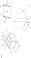
- Fig. 10 shows a filter cell according to the invention.
- the filter cell has a box-shaped housing and five rectangular filter plates 4 arranged in the housing.
- the housing has six housing surfaces, with two housing surfaces being designed as passage surfaces 1, 13, namely as an inlet surface with three rectangular inlet openings 6 and as an outlet surface with three rectangular outlet openings 18.
- the four remaining housing surfaces are designed as closed side surfaces connecting the two passage surfaces 1, 13 and form a flow channel with a rectangular cross section running from the inlet surface to the outlet surface.
- Each filter plate 4 has two longitudinal edges 8 and two parallel side edges 3 which are aligned parallel and parallel to the inlet openings 6 and to the outlet openings 18, one longitudinal edge 8 of each filter plate 4 sealingly resting against the inside of one passage surface 1, the other longitudinal edge 8 each filter plate 4 rests sealingly on the inside of the other passage surface 13 and the two side edges 3 of each filter plate 4 rest sealingly on the inside of one side surface.
- each filter plate 4 is selected in relation to the inlet openings 6 and the outlet openings 18 so that the air flowing into the housing through the inlet openings 6 and flowing out of the housing through the outlet openings 18 flows through a filter plate 4.
- Both passage surfaces 1, 13 have the same number of openings, namely three inlet openings 3 and three outlet openings 18, respectively.
- Each inlet opening 6 in one passage surface 1 is arranged congruently with the respective outlet opening 18 in the other passage surface 13.
- the inlet openings 6 and the corresponding outlet openings 18 are thus arranged in alignment when viewed in the general flow direction 19.
- the filter plates 4 have a course in the manner of saw teeth of a saw blade. Seen from left to right, in the exemplary embodiment shown, the first, third and fifth filter plates 4 are aligned obliquely, while the second and fourth filter plates 4 are aligned vertically. The angle of attack of the first, third and fifth filter plates 4 is therefore different from the angle of attack of the second and fourth filter plates 4.
Description
Die Erfindung betrifft ein Verfahren zur Montage einer Filterzelle für eine raumlufttechnische Anlage zur Abscheidung von Feinstaub und/oder von Schwebstoffen, wie beispielsweise von Aerosolen, von toxischen Stäuben, von Viren und/oder von Bakterien, aus der Zu- und Abluft, wobei die Filterzelle ein kastenförmiges Gehäuse sowie zumindest eine in dem Gehäuse angeordnete rechteckige Filterplatte aufweist, wobei das Gehäuse sechs Gehäuseflächen aufweist, wobei zwei Gehäuseflächen als Durchtrittsflächen, nämlich als Einlassfläche mit zumindest einer, vorzugsweise rechteckigen, Eintrittsöffnung und als Auslassfläche mit zumindest einer, vorzugsweise rechteckigen, Austrittsöffnung, ausgebildet sind und die vier verbleibenden Gehäuseflächen als die beiden Durchtrittsflächen verbindende geschlossene Seitenflächen ausgebildet sind und einen von der Einlassfläche zur Auslassfläche verlaufenden Strömungskanal mit rechteckigem Querschnitt bilden, wobei diese Filterplatte zwei parallel ausgerichtete und parallel zu der Eintrittsöffnung und zu der korrespondierenden Austrittsöffnung ausgerichtete Längskanten und zwei parallele Seitenkanten aufweist, wobei die eine Längskante dieser Filterplatte dichtend an der Innenseite der einen Durchtrittsfläche anliegt, die andere Längskante dieser Filterplatte dichtend an der Innenseite der anderen Durchtrittsfläche anliegt und die beiden Seitenkanten dieser Filterplatte dichtend an der Innenseite jeweils einer Seitenfläche anliegen, und wobei die Ausrichtung dieser Filterplatte in Bezug auf die Eintrittsöffnung und die Austrittsöffnung so gewählt ist, dass die durch die Eintrittsöffnung in das Gehäuse einströmende und durch die korrespondierende Austrittsöffnung aus dem Gehäuse ausströmende Luft diese Filterplatte durchströmt.The invention relates to a method for assembling a filter cell for a ventilation system for the separation of fine dust and/or suspended matter, such as aerosols, toxic dust, viruses and/or bacteria, from the supply and exhaust air, wherein the filter cell a box-shaped housing and at least one rectangular filter plate arranged in the housing, the housing having six housing surfaces, with two housing surfaces as passage surfaces, namely as an inlet surface with at least one, preferably rectangular, inlet opening and as an outlet surface with at least one, preferably rectangular, outlet opening, are designed and the four remaining housing surfaces are designed as closed side surfaces connecting the two passage surfaces and form a flow channel with a rectangular cross section running from the inlet surface to the outlet surface, this filter plate having two parallel aligned longitudinal edges and two parallel to the inlet opening and to the corresponding outlet opening has parallel side edges, one longitudinal edge of this filter plate resting sealingly on the inside of one passage surface, the other longitudinal edge of this filter plate resting sealingly on the inside of the other passage surface and the two side edges of this filter plate resting sealingly on the inside of one side surface, and whereby the The alignment of this filter plate in relation to the inlet opening and the outlet opening is selected so that the flow flowing into the housing through the inlet opening and through the corresponding one Air flowing out of the housing flows through this filter plate through the outlet opening.
Derartige Filterzellen eigenen sich für große Volumenströme und zeichnen sich durch lange Filterstandzeiten aus. Bekannte Filterzellen weisen ein Gehäuse auf, das aus sechs separat ausgebildeten Gehäuseflächen aufgebaut ist, die die sechs Seitenflächen des Gehäuses bilden. Zwei dieser sechs Gehäuseflächen sind als Durchtrittsflächen ausgebildet, die entweder zumindest eine Einlassöffnung bzw. zumindest eine Auslassöffnung aufweisen. Sofern eine Durchtrittsfläche mehr als eine Einlassöffnung bzw. mehr als eine Auslassöffnung aufweist, ist der jeweilige Bereich zwischen zwei benachbarten Eintritts- bzw. Austrittsöffnungen als separater Steg ausgebildet. Die sechs Seitenflächen und eventuelle Stege werden zusammengenietet und anschließend mit den Filterplatten mit einem flüssigen PU-Kleber dicht vergossen. Dieses Herstellverfahren ist aufgrund der hohen Anzahl an Einzelkomponenten, die zusammengesetzt werden müssen, sehr aufwändig. Auch sind wegen der langen Trocknungszeiten die Fertigungszeiten lang.Such filter cells are suitable for large volume flows and are characterized by long filter service lives. Known filter cells have a housing that is constructed from six separately formed housing surfaces that form the six side surfaces of the housing. Two of these six housing surfaces are designed as passage surfaces, which either have at least one inlet opening or at least one outlet opening. If a passage area has more than one inlet opening or more than one outlet opening, the respective area between two adjacent inlet or outlet openings is designed as a separate web. The six side surfaces and any webs are riveted together and then sealed with the filter plates using a liquid PU adhesive. This manufacturing process is very complex due to the high number of individual components that have to be assembled. The production times are also long because of the long drying times.
Aufgabe der Erfindung ist es, die vorgenannten Nachteile zu vermeiden und ein Verfahren anzugeben, mittels dem eine Filterzelle leichter und schneller herstellbar ist.The object of the invention is to avoid the aforementioned disadvantages and to provide a method by means of which a filter cell can be produced more easily and quickly.
Diese Aufgabe wird dadurch gelöst, dass eine Durchtrittsfläche jeweils mit den beiden an gegenüberliegenden Kanten angrenzenden Seitenflächen, die im zusammengesetzten Zustand mit einer Seitenkante jeder Filterplatte in Kontakt sind, einteilig ausgebildet ist und dass in Bezug auf die verbleibenden drei Gehäuseflächen die andere Durchtrittsfläche sowie die beiden anderen Seitenflächen jeweils separat oder aber einteilig mit zumindest einer der verbleibenden Gehäuseflächen ausgebildet ist(sind) und dass alle offenen Gehäusekanten verklebt und damit abgedichtet werden. Die sechs Gehäuseflächen sind jeweils in einem rechten Winkel zueinander ausgerichtet.This object is achieved in that a passage surface is formed in one piece with the two side surfaces adjacent to opposite edges, which in the assembled state are in contact with a side edge of each filter plate, and that in relation to the remaining three housing surfaces, the other passage surface as well as the two other side surfaces are each formed separately or in one piece with at least one of the remaining housing surfaces and that all open housing edges are glued and thus sealed. The six housing surfaces are each aligned at a right angle to one another.
Durch das erfindungsgemäße Verfahren wird die Filterzelle durch das Verkleben zum einen gegenüber der Umgebung im Bereich aller Kanten abgedichtet.By means of the method according to the invention, the filter cell is sealed from the environment in the area of all edges by gluing.
Ferner wird zum einen jede der beiden Durchtrittflächen im Kontaktbereich mit einer angrenzenden separat ausgebildeten Seitenfläche und zum anderen jede einteilig mit einer Durchtrittsfläche ausgebildete Seitenfläche im Kontaktbereich mit einer benachbarten separat ausgebildeten Seitenfläche fixiert. Insoweit sind alle offenen Kantenbereiche durch das Verkleben verschlossen.Furthermore, on the one hand, each of the two passage surfaces is fixed in the contact area with an adjacent, separately formed side surface and, on the other hand, each side surface formed in one piece with a passage surface is fixed in the contact area with an adjacent, separately formed side surface. In this respect, all open edge areas are closed by gluing.
Durch das erfindungsgemäße Verfahren können die Montagezeit und die Durchlaufzeit deutlich reduziert werden. Insoweit erlaubt das erfindungsgemäße Verfahren eine deutlich schnellere Herstellung einer Filterzelle. Das Gehäuse kann beispielsweise aus nur vier Teilen, beispielsweise aus vier Blechteilen, und der entsprechenden Anzahl an gewünschten Filterplatten hergestellt werden. Durch den Einsatz des erfindungsgemäßen Verfahrens kann auch die Konstruktion der Filterzelle selbst vereinfacht werden. Es sind keine Nieten oder Schrauben erforderlich. Auch ein Schweißen ist nicht erforderlich. Ferner kann das Gesamtgewicht bei gleichzeitig geringerem Kleberverbrauch reduziert werden. Dies führt zu einer Reduzierung der Herstellkosten. Der verwendete Kleber dient sowohl der Abdichtung des Gehäuses als auch der Fixierung der Gehäuseflächen, d. h. der Kleber sorgt für die Dichtigkeit und für die Stabilisierung des Gehäuses.The method according to the invention allows the assembly time and the throughput time to be significantly reduced. In this respect, the method according to the invention allows a filter cell to be manufactured much more quickly. The housing can, for example, be made from only four parts, for example four sheet metal parts, and the corresponding number of desired filter plates. By using the method according to the invention, the construction of the filter cell itself can also be simplified. No rivets or screws are required. Welding is also not necessary. Furthermore, the overall weight can be reduced while at the same time using less adhesive. This leads to a reduction in manufacturing costs. The adhesive used serves both to seal the housing and to fix the housing surfaces, i.e. H. The adhesive ensures the tightness and stabilization of the housing.
Die mittels des erfindungsgemäßen Verfahrens hergestellte Filterzelle kann beispielsweise als Mini Pleat Filterzelle für die Abscheidung von Feinstaub und von Schwebstoffen wie z. B. Aerosolen, toxischen Stäuben, Viren, Bakterien aus der Zu- und Abluft in raumlufttechnischen Anlagen mit großen Volumenströmen und mit langen Filterstandzeiten eingesetzt werden. Die Filterzelle kann auch zur Feinstaubfilterung als Vor- oder Endfilter in raumlufttechnischen Anlagen zur Abscheidung von Feinstaub eingesetzt werden. Die Filterzellen eignen sich auch als Schwebstofffilter in Form eines Hauptfilters oder eines Endfilters, sofern hohe Anforderungen an die Luftreinheit und die Keimfreiheit beispielsweise in der Industrie, in der Forschung, in der Medizin, in der Pharmazie oder in der Nukleartechnik erzielt werden sollen.The filter cell produced using the method according to the invention can, for example, be used as a mini pleat filter cell for the separation of fine dust and suspended matter such as. B. aerosols, toxic dusts, viruses, bacteria from the supply and exhaust air in ventilation systems with large volume flows and long filter life. The filter cell can also be used for fine dust filtering as a pre- or final filter in air conditioning systems to separate fine dust. The filter cells are also suitable as a suspended matter filter in the form of a main filter or a final filter if high requirements for air purity and freedom from germs are to be achieved, for example in industry, research, medicine, pharmacy or nuclear technology.
Es bietet sich an, wenn vor dem Einsetzen der Filterplatte(n) in das herzustellende Gehäuse auf die Innenseite jeder Durchtrittsfläche in dem Bereich, der im zusammengesetzten Zustand mit einer Längskante jeder Filterplatte in Kontakt ist, und auf die Innenseite jeder der zwei Seitenflächen, die im zusammengesetzten Zustand mit einer Seitenkante jeder Filterplatte in Kontakt sind, Kleber aufgebracht wird. Bei einer solchen Ausgestaltung bewirkt der Kleber zusätzlich zum einen eine Fixierung der Filterplatten in dem Gehäuse und zum anderen eine Abdichtung der Filterplatte gegenüber der Innenseite der jeweiligen Gehäusefläche.It is advisable if, before inserting the filter plate(s) into the housing to be manufactured, on the inside of each passage surface in the area in contact with a longitudinal edge of each filter plate in the assembled state, and adhesive is applied to the inside of each of the two side surfaces that are in contact with a side edge of each filter plate in the assembled state. In such a configuration, the adhesive also effects, on the one hand, a fixation of the filter plates in the housing and, on the other hand, a sealing of the filter plate against the inside of the respective housing surface.
Bei einer bevorzugten Ausführungsform kann eine Durchtrittsfläche jeweils mit den beiden an gegenüberliegenden Kanten angrenzenden Seitenflächen, die im zusammengesetzten Zustand mit einer Seitenkante jeder Filterplatte in Kontakt sind, einteilig ausgebildet sein und in Bezug auf die verbleibenden drei Gehäuseflächen die andere Durchtrittsfläche sowie die beiden anderen Seitenflächen jeweils separat ausgebildet sein,
- wobei die Durchtrittsfläche und die beiden einteilig mit dieser Durchtrittsfläche ausgebildeten Seitenflächen als, vorzugsweise durch Stanzen erzeugte, Platine ausgebildet sind,
- wobei auf die Innenseite der Durchtrittsfläche in den Bereichen, die im zusammengesetzten Zustand mit einer Längskante einer Filterplatte in Kontakt sind, und auf die Innenseite jeder der zwei Seitenflächen, die im zusammengesetzten Zustand mit einer Seitenkante jeder Filterplatte in Kontakt sind, Kleber aufgebracht wird,
- wobei, vorzugsweise anschließend, auf den mit dem Kleber versehenen Bereich der Durchtrittsfläche jede Filterplatte mit einer ihrer beiden Längskanten aufgesetzt wird,
- wobei, vorzugsweise anschließend, die beiden angrenzenden Seitenflächen so verlagert, vorzugsweise umgebogen, werden, bis sie mit der jeweils angrenzenden Seitenkante jeder Filterplatte in Kontakt sind,
- wobei, vorzugsweise anschließend, die beiden seitlichen offenen Gehäuseflächen mit je einer Seitenfläche verschlossen werden und
- wobei, vorzugsweise anschließend, die oben offene Gehäusefläche mit der anderen Durchtrittsfläche verschlossen wird, wobei vor dem Verschließen auf die freie Längskante jeder Filterplatte und/oder auf die Innenseite der anderen Durchtrittsfläche in den Bereichen, die im zusammengesetzten Zustand mit der Längskante einer Filterplatte in Kontakt sind, Kleber aufgebracht wird.
- wherein the passage surface and the two side surfaces formed in one piece with this passage surface are designed as a circuit board, preferably produced by punching,
- wherein adhesive is applied to the inside of the passage surface in the areas that are in contact with a longitudinal edge of a filter plate in the assembled state and to the inside of each of the two side surfaces that are in contact with a side edge of each filter plate in the assembled state,
- wherein, preferably subsequently, each filter plate is placed with one of its two longitudinal edges onto the area of the passage surface provided with the adhesive,
- wherein, preferably subsequently, the two adjacent side surfaces are displaced, preferably bent, until they are in contact with the respective adjacent side edge of each filter plate,
- wherein, preferably subsequently, the two open side housing surfaces are each closed with a side surface and
- wherein, preferably subsequently, the housing surface, which is open at the top, is closed with the other passage surface, before closing on the free longitudinal edge of each filter plate and / or on the inside of the other passage surface in the areas that are in contact with the longitudinal edge of a filter plate in the assembled state are, glue is applied.
Bei einer solchen Ausgestaltung besteht das Gehäuse aus vier Teilen, nämlich der Durchtrittsfläche mit den beiden einteilig mit dieser Durchtrittsfläche ausgebildeten Seitenflächen sowie der anderen Durchtrittsfläche sowie den zwei separat ausgebildeten Seitenflächen.In such a configuration, the housing consists of four parts, namely the passage surface with the two side surfaces formed in one piece with this passage surface and the other passage surface and the two separately formed side surfaces.
Nach dem Verschließen des Gehäuses mit der anderen Durchtrittsfläche kann das zusammengesetzte Gehäuse, vorzugsweise bis zum Aushärten des Klebers, in einen Rahmen gespannt werden. Der Rahmen sorgt für eine optimale Ausrichtung der zusammengeklebten Gehäuseflächen und verhindert, dass sich miteinander verklebte Gehäuseflächen und infolgedessen auch die im Inneren des Gehäuses befindlichen Filterplatten in ihrer Position verändern, solange der Kleber noch nicht hinreichend getrocknet ist.After closing the housing with the other passage surface, the assembled housing can be clamped into a frame, preferably until the adhesive has hardened. The frame ensures optimal alignment of the housing surfaces glued together and prevents the housing surfaces glued together and, as a result, the filter plates inside the housing from changing in position as long as the glue has not yet dried sufficiently.
Dabei kann vor dem Aufsetzen einer Filterplatte auf den mit dem Kleber versehenen Bereich der Durchtrittsfläche, die mit den beiden an gegenüberliegenden Kanten angrenzenden Seitenflächen, die im zusammengesetzten Zustand mit einer Seitenkante jeder Filterplatte in Kontakt sind, einteilig ausgebildet sein, durch die betreffende(n) Eintritts- bzw. Austrittsöffnung(en) ein Anlageelement mit zumindest einer Anlagefläche geführt werden, wobei die Anzahl an Anlageflächen der Anzahl an aufzusetzenden Filterplatten entspricht. Die zu einer Eintritts- bzw. Austrittsöffnung gehörenden Anlageflächen können schräg aufeinander zuweisend ausgerichtet sein und damit eine dachähnliche Ausbildung haben. Nach Einführen in die betreffende Eintritts- bzw. Austrittsöffnungen können die beiden Filterplatten an die Anlageflächen des Anlageelementes angelegt werden. Die Filterplatten können nach dem Aufsetzen nicht ungewollt umkippen. Während der Trocknung des Klebers liegen die aufgesetzten Filterplatten an der jeweiligen Anlagefläche an.Before placing a filter plate on the area of the passage surface provided with the adhesive, the two side surfaces adjacent to opposite edges, which in the assembled state are in contact with a side edge of each filter plate, can be formed in one piece by the relevant Inlet or outlet opening(s) a contact element with at least one contact surface is guided, the number of contact surfaces corresponding to the number of filter plates to be placed. The contact surfaces belonging to an inlet or outlet opening can be aligned obliquely towards one another and thus have a roof-like design. After being inserted into the relevant inlet and outlet openings, the two filter plates can be placed on the contact surfaces of the contact element become. The filter plates cannot accidentally tip over after being put on. While the adhesive is drying, the attached filter plates rest against the respective contact surface.
Sowohl die beiden gegenüberliegenden Kanten der Durchtrittsfläche als auch die gegenüberliegenden Kanten der beiden Seitenflächen, die einteilig mit dieser Durchtrittsfläche ausgebildet sind, können jeweils eine Abkantung aufweisen, wobei die Abkantungen im zusammengesetzten Zustand des Gehäuses in Richtung der durch diese Abkantungen an drei Seiten umschließenden Gehäusefläche zugewandt sind. Die Abkantungen weisen vorzugsweise eine maximale Höhe von rund 20 mm auf. Diese Abkantungen sind ausreichend, um eine hinreichende Kontaktfläche, die beispielsweise mit Kleber versehen werden kann, zu der angrenzenden Gehäusefläche und damit eine ausreichende Fixierung nach Aufbringen von Kleber zu gewährleisten. Auf der anderen Seite erlaubt eine Abkantung in diesem Maße auch das Einlegen in einer CNC-Klebeauftragsmaschine.Both the two opposite edges of the passage surface and the opposite edges of the two side surfaces, which are formed in one piece with this passage surface, can each have a fold, the folds facing in the assembled state of the housing in the direction of the housing surface enclosing these folds on three sides are. The folds preferably have a maximum height of around 20 mm. These folds are sufficient to ensure a sufficient contact surface, which can be provided with adhesive, for example, to the adjacent housing surface and thus sufficient fixation after application of adhesive. On the other hand, a fold of this size also allows it to be inserted into a CNC adhesive application machine.
Der Abstand zwischen den gegenüberliegenden Abkantungen der Durchtrittsfläche kann, vorzugsweise um die vierfache Materialstärke der Abkantung, größer sein als der Abstand zwischen den jeweils gegenüberliegenden Abkantungen jeder Seitenfläche.The distance between the opposite folds of the passage surface can be larger, preferably four times the material thickness of the fold, than the distance between the opposite folds of each side surface.
Bei zumindest einer separat ausgebildeten Seitenfläche weisen die beiden gegenüberliegenden Kanten, die im zusammengesetzten Zustand in Kontakt mit einer anderen Seitenfläche sind, jeweils eine Abkantung auf, wobei jede der beiden Abkantungen im zusammengesetzten Zustand des Gehäuses an der Außenseite der jeweils angrenzenden Seitenfläche anliegt. Der Abstand zwischen den Abkantungen zweier gegenüberliegenden Kanten ist insoweit etwas größer als die Breite des Gehäuses. Die Abkantungen weisen vorzugsweise eine maximale Höhe von rund 20 mm auf.In the case of at least one separately formed side surface, the two opposite edges, which are in contact with another side surface in the assembled state, each have a fold, with each of the two folds in the assembled state of the housing resting on the outside of the respectively adjacent side surface. The distance between the folds of two opposite edges is slightly larger than the width of the housing. The folds preferably have a maximum height of around 20 mm.
Zumindest zwei gegenüberliegende Kanten, vorzugsweise alle vier Kanten, der anderen Durchtrittfläche weisen jeweils eine Abkantung auf, wobei die andere Durchtrittsfläche so angebracht wird, dass jede der zwei, vorzugsweise vier, Abkantungen im zusammengesetzten Zustand des Gehäuses an der Außenseite der jeweils angrenzenden Seitenfläche anliegt. Auch hier ist der Abstand zwischen den Abkantungen im Bereich zweier gegenüberliegender Kanten etwas größer als die Breite des Gehäuses. Die Abkantungen weisen vorzugsweise eine maximale Höhe von rund 20 mm auf.At least two opposite edges, preferably all four edges, of the other passage surface each have a fold, the other passage surface being attached in such a way that each of the two, preferably four, Folds in the assembled state of the housing rest on the outside of the adjacent side surface. Here too, the distance between the folds in the area of two opposite edges is slightly larger than the width of the housing. The folds preferably have a maximum height of around 20 mm.
Die Durchtrittsfläche und die beiden einteilig mit dieser Durchtrittsfläche ausgebildeten Seitenflächen und/oder die andere Durchtrittsfläche und/oder die beiden anderen Seitenflächen kann(können) aus Blech bestehen.The passage surface and the two side surfaces formed in one piece with this passage surface and/or the other passage surface and/or the other two side surfaces can be made of sheet metal.
Der Kleber kann Polyurethan umfassen. Bei einer solchen Ausgestaltung ist der Kleber als PU-Kleber ausgebildet.The adhesive may include polyurethane. In such a configuration, the adhesive is designed as a PU adhesive.
Mehrere Filterplatten können zickzackförmig in dem Gehäuse derart angeordnet werden, dass sich zwei benachbarte Filterplatten jeweils an einer Längskante berühren und die sich berührenden Längskanten in dem Bereich der Innenseite der angrenzenden Durchtrittsfläche in Kontakt sind, der zwischen zwei benachbarten Eintrittsöffnungen bzw. zwischen zwei benachbarten Austrittsöffnungen angeordnet ist. Bei einem zickzackförmigen Verlauf ist der Anstellwinkel bei allen Filterplatten gleich.Several filter plates can be arranged in a zigzag shape in the housing in such a way that two adjacent filter plates each touch each other on a longitudinal edge and the touching longitudinal edges are in contact in the area of the inside of the adjacent passage surface, which is arranged between two adjacent inlet openings or between two adjacent outlet openings is. With a zigzag shape, the angle of attack is the same for all filter plates.
Es ist aber auch durchaus möglich, dass die Anordnung der Filterplatten in dem Gehäuse nach Art von Sägezähnen eines Sägeblattes ausgebildet ist, wobei sich zwei benachbarte Filterplatten jeweils an einer ihrer beiden Längskanten berühren und die beiden sich jeweils berührenden Längskanten in dem Bereich mit der Innenseite der angrenzenden Durchtrittsfläche in Kontakt sind, der zwischen zwei benachbarten Eintrittsöffnungen bzw. zwischen zwei benachbarten Austrittsöffnungen angeordnet ist. Bei einer solchen Anordnung ist der Anstellwinkel der ersten, der dritten, der fünften usw. Filterplatte ungleich dem Anstellwinkel der zweiten, der vierten, usw. Filterplatte.However, it is also entirely possible for the arrangement of the filter plates in the housing to be designed in the manner of saw teeth of a saw blade, with two adjacent filter plates touching each other on one of their two longitudinal edges and the two touching longitudinal edges in the area with the inside of the adjacent passage surface are in contact, which is arranged between two adjacent inlet openings or between two adjacent outlet openings. With such an arrangement, the angle of attack of the first, third, fifth, etc. filter plates is unequal to the angle of attack of the second, fourth, etc. filter plates.
In der einen Durchtrittsfläche können mehrere, parallel zueinander angeordnete Eintrittsöffnungen, und/oder in der anderen Durchtrittsfläche können mehrere parallel zueinander angeordnete Austrittsöffnungen vorgesehen sein. Die Eintrittsöffnungen und die Austrittsöffnungen können in der generellen Strömungsrichtung gesehen versetzt zueinander angeordnet sein. Bei einer solchen Ausgestaltung ist die Anzahl an Eintrittsöffnungen üblicherweise um eine Öffnung größer als die Anzahl an Austrittsöffnungen.A plurality of inlet openings arranged parallel to one another can be provided in one passage surface, and/or a plurality of outlet openings arranged parallel to one another can be provided in the other passage surface. The entrance openings and the outlet openings can be arranged offset from one another as viewed in the general direction of flow. In such a configuration, the number of inlet openings is usually one opening larger than the number of outlet openings.
Im Folgenden werden in den Zeichnungen dargestellte Ausführungsbeispiele der Erfindung erläutert. Es zeigen:
- Fig. 1a
- eine schräge Draufsicht auf eine Platine aus Blech, umfassend eine Durchtrittsfläche, die einteilig mit an zwei gegenüberliegenden Kanten angrenzenden Seitenflächen ausgebildet ist, die im zusammengesetzten Zustand mit einer Seitenkante jeder Filterplatte in Kontakt sind, wobei sowohl die beiden gegenüberliegenden Kanten der Durchtrittsfläche als auch die gegenüberliegenden Kanten der beiden Seitenflächen jeweils eine Abkantung aufweisen,
- Fig. 1b
- das Detail "b" aus
Fig. 1a , - Fig. 1c
- einen Schnitt in Richtung c-c durch den Teilbereich des Gegenstandes nach
Fig. 1a , - Fig. 2
- den Gegenstand nach
Fig. 1a , wobei auf der Durchtrittsfläche insgesamt sechs Filterplatten zickzackförmig angeordnet sind, - Fig. 3a
- eine Draufsicht auf den Gegenstand nach
Fig. 2 , wobei die Seitenflächen nach oben umgebogen worden sind, - Fig. 3b
- das Detail "b" aus
Fig. 3a , - Fig. 4a
- den Gegenstand nach
Fig. 3a , wobei die beiden seitlich offenen Gehäuseflächen mit je einer separat ausgebildeten Seitenfläche verschlossen worden sind, - Fig. 4b
- das Detail "b" aus
Fig. 4a , - Fig. 4c
- eine schräge Draufsicht auf eine separat ausgebildete Seitenfläche,
- Fig. 5a
- den Gegenstand nach
Fig. 4a , wobei die oben offene Gehäusefläche mit der anderen, separat ausgebildeten Durchtrittsfläche verschlossen worden ist, - Fig. 5b
- das Detail "b" aus
Fig. 5a , - Fig. 5c
- ein Ansicht auf die Innenseite der separat ausgebildeten Durchtrittsfläche,
- Fig. 6
- einen Rahmen zum Einspannen des zusammengesetzten Gehäuses im ausgeklappten Zustand,
- Fig. 7
- den Rahmen nach Einsetzen der zusammengesetzten Filterzelle,
- Fig. 8
- den verschlossenen Rahmen mit der darin eingespannten Filterzelle,
- Fig. 9
- eine Draufsicht auf ein Anlageelement und
- Fig. 10
- einen Schnitt durch eine erfindungsgemäße Filterzelle.
- Fig. 1a
- an oblique plan view of a sheet metal circuit board, comprising a passage surface which is formed in one piece with side surfaces adjacent to two opposite edges, which in the assembled state are in contact with a side edge of each filter plate, both the two opposite edges of the passage surface and the opposite ones Edges of the two side surfaces each have a fold,
- Fig. 1b
- the detail “b”.
Fig. 1a , - Fig. 1c
- a cut in the direction cc through the partial area of the object
Fig. 1a , - Fig. 2
- the object
Fig. 1a , with a total of six filter plates arranged in a zigzag shape on the passage surface, - Fig. 3a
- a top view of the object
Fig. 2 , whereby the side surfaces have been bent upwards, - Fig. 3b
- the detail “b”.
Fig. 3a , - Fig. 4a
- the object
Fig. 3a , whereby the two laterally open housing surfaces have each been closed with a separately designed side surface, - Fig. 4b
- the detail “b”.
Fig. 4a , - Fig. 4c
- an oblique top view of a separately formed side surface,
- Fig. 5a
- the object
Fig. 4a , whereby the housing surface, which is open at the top, has been closed with the other, separately formed passage surface, - Fig. 5b
- the detail “b”.
Fig. 5a , - Fig. 5c
- a view of the inside of the separately formed passage area,
- Fig. 6
- a frame for clamping the assembled housing in the unfolded state,
- Fig. 7
- the frame after inserting the assembled filter cell,
- Fig. 8
- the closed frame with the filter cell clamped inside,
- Fig. 9
- a top view of an investment element and
- Fig. 10
- a section through a filter cell according to the invention.
In allen Figuren werden für gleiche bzw. gleichartige Bauteile übereinstimmende Bezugszeichen verwendet.In all figures, identical reference symbols are used for identical or similar components.
Um das spätere Hochbiegen der Seitenflächen 2 zu erleichtern, kann im Bereich der jeweiligen Biegelinie beispielsweise eine Einkerbung 5 eingebracht worden sein. In dem dargestellten Ausführungsbeispiel sind in der Durchtrittsfläche 1 drei Öffnungen, bei denen es sich beispielsweise um Eintrittsöffnungen 6 handeln kann, vorgesehen, die rechteckig ausgebildet sind.In order to make the later bending of the side surfaces 2 easier, a
Wie
Wie
Wie
In einem nächsten Schritt werden auf die mit Kleber 9 versehenen Bereiche der Durchtrittsfläche 1 die Filterplatten 4 aufgesetzt. Dies ist in
Dann werden die beiden angrenzenden Seitenflächen 2 so verlagert (umgebogen), bis sie mit der jeweils angrenzenden Seitenkante 3 jeder Filterplatte 4 in Kontakt sind. Dies ist in
Da der Abstand der gegenüberliegenden Abkantungen 7 im Bereich jeder Seitenfläche 2 kleiner als der Abstand der Abkantungen 7 im Bereich der Durchtrittsfläche 1 ist, stehen die Abkantungen 7 der Durchtrittsfläche 1 nach dem Umbiegen gegenüber den Abkantungen 7 der Seitenfläche 2 außenseitig vor. Damit verbleibt im umgebogenen Zustand ein Spalt 10 zwischen der Abkantung 7 der Durchtrittsfläche 1 und der Abkantung 7 der Seitenfläche 2. Die Breite des Spaltes 10 entspricht zumindest der Materialstärke einer nunmehr anzubringenden, separat ausgebildeten Seitenfläche 11.Since the distance between the
Selbstverständlich ist es auch möglich, dass vor dem Aufsetzen der Filterplatten 4 die Seitenflächen 2 bereits etwas aus der in
Nunmehr werden die beiden seitlichen offenen Gehäuseflächen mit je einer Seitenfläche 11 verschlossen. Jede der beiden Seitenflächen 11 wird dabei so angebracht, dass jede Seitenfläche 11 auf beiden Seiten in den Spalt 10 eingeführt ist. Dieser Zustand ist in
Wie in
In einem letzten Schritt wird die noch oben offene Gehäusefläche mit einer anderen Durchtrittsfläche 13, deren vier Seiten jeweils eine Abkantung 14 aufweisen, verschlossen. In der Durchtrittsfläche 13 sind rechteckige Austrittsöffnungen 18 vorgesehen. Wie in
Nach dem Aufsetzen der Durchtrittsfläche 13 liegt jede der vier Abkantungen 14 der anderen Durchtrittsfläche 13 auf der Außenseite der jeweils angrenzenden Seitenflächen 2, 11 an. Die Längskanten der Eintrittsöffnungen 6 und die Längskanten der Austrittsöffnungen 18 weisen die gleiche Ausrichtung wie die Längskanten 8 jeder Filterplatte 4 auf.After the
Um eine Verschiebung der Gehäuseteile bei noch nicht getrocknetem Kleber 9 zu verhindern, kann die Filterzelle in einen Rahmen 15 eingespannt werden. Wie den
In
Das Gehäuse weist sechs Gehäuseflächen auf, wobei zwei Gehäuseflächen als Durchtrittsflächen 1, 13, nämlich als Einlassfläche mit drei rechteckigen Eintrittsöffnungen 6 und als Auslassfläche mit drei rechteckigen Austrittsöffnungen 18, ausgebildet sind. Die vier verbleibenden Gehäuseflächen sind als die beiden Durchtrittsflächen 1, 13 verbindende geschlossene Seitenflächen ausgebildet und bilden einen von der Einlassfläche zur Auslassfläche verlaufenden Strömungskanal mit einem rechteckigen Querschnitt.The housing has six housing surfaces, with two housing surfaces being designed as passage surfaces 1, 13, namely as an inlet surface with three
Jede Filterplatte 4 weist zwei parallel ausgerichtete und parallel zu den Eintrittsöffnungen 6 und zu den Austrittsöffnungen 18 ausgerichtete Längskanten 8 und zwei parallele Seitenkanten 3 auf, wobei die eine Längskante 8 jeder Filterplatte 4 dichtend an der Innenseite der einen Durchtrittsfläche 1 anliegt, die andere Längskante 8 jeder Filterplatte 4 dichtend an der Innenseite der anderen Durchtrittsfläche 13 anliegt und die beiden Seitenkanten 3 jeder Filterplatte 4 dichtend an der Innenseite jeweils einer Seitenfläche anliegen.Each
Die Ausrichtung jeder Filterplatte 4 ist in Bezug auf die Eintrittsöffnungen 6 und die Austrittsöffnungen 18 so gewählt, dass die durch die Eintrittsöffnungen 6 in das Gehäuse einströmende und durch die Austrittsöffnungen 18 aus dem Gehäuse ausströmende Luft eine Filterplatte 4 durchströmt.The orientation of each
Beide Durchtrittsflächen 1, 13 weisen die gleiche Anzahl an Öffnungen, nämlich drei Eintrittsöffnungen 3 bzw. drei Austrittsöffnungen 18, auf. Jede Eintrittsöffnung 6 in der einen Durchtrittsfläche 1 ist deckungsgleich zu der jeweiligen Austrittsöffnung 18 in der anderen Durchtrittsfläche 13 angeordnet. Damit sind die Eintrittsöffnungen 6 und die korrespondierenden Austrittsöffnungen 18 in der generellen Strömungsrichtung 19 gesehen fluchtend angeordnet.Both passage surfaces 1, 13 have the same number of openings, namely three
In dem dargestellten Ausführungsbeispiel weisen die Filterplatten 4 einen Verlauf nach Art von Sägezähnen eines Sägeblattes auf. Von links nach rechts gesehen sind in dem dargestellten Ausführungsbeispiel die erste, die dritte und die fünfte Filterplatte 4 schräg ausgerichtet, während die zweite und die vierte Filterplatte 4 senkrecht ausgerichtet sind. Der Anstellwinkel der ersten, der dritten und der fünften Filterplatte 4 ist insoweit ungleich dem Anstellwinkel der zweiten und der vierten Filterplatte 4.In the exemplary embodiment shown, the
Claims (13)
- Method for mounting a filter cell for a room air installation for screening out fine dust and/or substances in suspension, such as aerosols, toxic dusts, viruses and/or bacteria, from the incoming and outgoing air, wherein the filter cell comprises a box-shaped housing and at least one rectangular filter plate (4) arranged in the housing, wherein the housing comprises six housing surfaces, wherein two housing surfaces are configured as passage surfaces (1, 13), namely as an inlet surface with at least one, preferably rectangular, inlet opening (6), and as an outlet surface (18), and the four remaining housing surfaces are configured as closed side surfaces connecting the passage surfaces (1, 13), and a flow channel running from the inlet surface to the outlet surface with a rectangular cross-section, wherein this filter plate (4) comprises two longitudinal edges (8), aligned in parallel and aligned parallel to the inlet opening (6) and to the corresponding outlet opening (18), and two parallel side edges (3), wherein the one longitudinal edge (8) of this filter plate (4) is in sealing contact with the inner side of the one passage surface (1), the other longitudinal edge (8) of this filter plate (4) is in sealing contact with the inner side of the other passage surface (13), and the two side edges (3) of this filter plate (4) are in sealing contact on the inner side in each case of a side surface (2), and wherein the alignment of this filter plate (4) is selected in relation to the inlet opening (6) and the outlet opening (18) in such a way that the air flowing in through the inlet opening (6) into the housing, and flowing out through the corresponding outlet opening (18) out of the housing, flows through this filter plate (4), characterised in that a passage surface (1) is configured in each case as being of one piece with the two adjacent side surfaces (2) on opposing edges, which in the assembled state are in contact with a side edge (3) of each filter plate (4), and that, in relation to the remaining three housing surfaces, the other passage surface (13) and the two other side surfaces (11) is (are) in each case configured as separate, but also as of one piece with at least one of the remaining housing surfaces, and that all the open housing edges are adhesively bonded and are therefore sealed.
- Method according to the preceding claim, characterised in that, before the insertion of the filter plate(s) (4) into the housing which is to be produced, adhesive (9) is applied onto the inner side of each passage surface (1, 13), in the region which in the assembled state is in contact with a longitudinal edge (8) of each filter plate (4), and onto the inner side of each of the two side surfaces (2), which in the assembled state are in contact with a side edge (3) of each filter plate (4).
- Method according to any one of the preceding claims, characterised in that one passage surface (1) is configured in each case as being of one piece with the two side surfaces (2) adjacent on the opposing edges, which in the assembled state are in contact with a side edge (3) of each filter plate (4), and that, in relation to the remaining three housing surfaces, the other passage surface (13) and the other two side surfaces (11) are in each case configured separately,- wherein the passage surface (1), and the two side surfaces (2) configured as being of one piece with this passage surface (1), are configured as sheets, preferably produced by punching,- wherein adhesive (9) is applied onto the inner side of the passage surface (1) in the regions which, in the assembled state, are in contact with a longitudinal edge (8) of a filter plate (4), and onto the inner sides of each of the two side surfaces (2) which, in the assembled state, are in contact with a side edge (3) of each filter plate (4),- wherein each filter plate (4) is placed with one of its two longitudinal edges (8) onto the region of the passage surface (1) which has been provided with adhesive (9),- wherein the two adjacent side surfaces (2) are displaced, preferable bent, until they are in contact in each case with the adjacent side edge (2) of each filter plate (3),- wherein the two open side housing surfaces are each closed by a side surface (11), and- wherein the upper open housing surface is closed with the other passage surface (13), wherein, before the closing, adhesive (9) is applied onto the free longitudinal edge (8) of the filter plate (4) and/or onto the inner side of the other passage surface (13) in the regions which, in the assembled state, are in contact with the longitudinal edge (8) of a filter plate (4).
- Method according to any one of the preceding claims, characterised in that, after the closing of the housing with the other passage surface (13), the assembled housing is tensioned in a frame (15), preferably until the adhesive (9) has hardened.
- Method according to any one of the preceding claim, characterised in that, before the placing of a filter plate (4) onto the region of the passage surface (1) provided with the adhesive (9), the side surfaces (2) adjacent to the two opposing edges, which in the assembled state are in contact with a side edge (3) of each filter plate (4), are configured as being of one piece, a contact element (16) is guided through the respective inlet and outlet opening(s) (6, 18) concerned, with at least one contact surface (17), wherein the number of contact surfaces (17) corresponds to the number of filter plates (4) which are to be placed.
- Method according to any one of the preceding claims, characterised in that both the two opposing edges of the passage surface (1) as well as the opposing edges of the two side surfaces (2), which are configured as being of one piece with this passage surface (1), comprise in each case a bevelled edge (7), wherein, in the assembled state of the housing, the bevelled edges (7) face in the direction towards the housing surface which is enclosed on three sides by these bevelled edges (7).
- Method according to the preceding claim, characterised in that the distance interval between the opposing bevelled edges (7) of the passage surface (1) is greater, preferably by four times the material thickness of the bevelled edge (7), than the distance interval between the respective opposing bevelled edges (7) of each side surface (2).
- Method according to any one of the preceding claims, characterised in that with at least one side surface (11) configured separately, the two opposing edges which, in the assembled state, are in contact with another side surface (2), in each case comprise a bevelled edge (12), wherein each of the two bevelled edges (12), in the assembled state of the housing, are in contact on the outside of the respective adjacent side surface (2).
- Method according to any one of the preceding claims, characterised in that at least two opposing edges, and preferably all four edges, of the other passage surface (13) in each case comprise a bevelled edging (14), wherein the other passage surface (13) is arranged in such a way that each of the two, and preferably four, bevelled edges (14) are, in the assembled state of the housing, in contact on the outside of the respective adjacent side surface (2, 11).
- Method according to any one of the preceding claims, characterised in that the passage surface (1) and the two side surfaces (2), configured as being of one piece with this passage surface (1), and/or the other passage surface (13), and/or the two other side surfaces (11) consist(s) of sheet metal.
- Method according to any one of the preceding claims, characterised in that the adhesive (9) comprises polyurethane.
- Method according to any one of the preceding claims, characterised in that several filter plates (4) are arranged in a zigzag shape in the housing, in such a way that two adjacent filter plates (4) are in each case in contact on a longitudinal edge (8), and the longitudinal edges (8) touching one another are in contact in a region of the inner side of the adjacent passage surface (13), which is arranged between two adjacent inlet openings (6) or, respectively, between two adjacent outlet openings (18).
- Method according to any one of the preceding claims, characterised in that several inlet openings (6), arranged parallel to one another, are provided in the one passage surface (1, 13), and/or several outlet openings (18), arranged parallel to one another, are provided in the other passage surface (13, 1).
Priority Applications (4)
| Application Number | Priority Date | Filing Date | Title |
|---|---|---|---|
| HRP20240113TT HRP20240113T1 (en) | 2021-03-24 | 2021-03-24 | Method for mounting a filter cell for a room air installation |
| RS20240157A RS65249B1 (en) | 2021-03-24 | 2021-03-24 | Method for mounting a filter cell for a room air installation |
| EP21164518.9A EP4062994B9 (en) | 2021-03-24 | 2021-03-24 | Method for mounting a filter cell for a room air installation |
| PL21164518.9T PL4062994T3 (en) | 2021-03-24 | 2021-03-24 | Method for mounting a filter cell for a room air installation |
Applications Claiming Priority (1)
| Application Number | Priority Date | Filing Date | Title |
|---|---|---|---|
| EP21164518.9A EP4062994B9 (en) | 2021-03-24 | 2021-03-24 | Method for mounting a filter cell for a room air installation |
Publications (4)
| Publication Number | Publication Date |
|---|---|
| EP4062994A1 EP4062994A1 (en) | 2022-09-28 |
| EP4062994C0 EP4062994C0 (en) | 2023-11-08 |
| EP4062994B1 true EP4062994B1 (en) | 2023-11-08 |
| EP4062994B9 EP4062994B9 (en) | 2024-01-17 |
Family
ID=75203151
Family Applications (1)
| Application Number | Title | Priority Date | Filing Date |
|---|---|---|---|
| EP21164518.9A Active EP4062994B9 (en) | 2021-03-24 | 2021-03-24 | Method for mounting a filter cell for a room air installation |
Country Status (4)
| Country | Link |
|---|---|
| EP (1) | EP4062994B9 (en) |
| HR (1) | HRP20240113T1 (en) |
| PL (1) | PL4062994T3 (en) |
| RS (1) | RS65249B1 (en) |
Family Cites Families (2)
| Publication number | Priority date | Publication date | Assignee | Title |
|---|---|---|---|---|
| US3246457A (en) * | 1962-04-19 | 1966-04-19 | Farr Co | Pleated air filter cartridge |
| US5693108A (en) * | 1995-09-15 | 1997-12-02 | Consler Corporation | One-piece filter housing |
-
2021
- 2021-03-24 EP EP21164518.9A patent/EP4062994B9/en active Active
- 2021-03-24 PL PL21164518.9T patent/PL4062994T3/en unknown
- 2021-03-24 RS RS20240157A patent/RS65249B1/en unknown
- 2021-03-24 HR HRP20240113TT patent/HRP20240113T1/en unknown
Also Published As
| Publication number | Publication date |
|---|---|
| HRP20240113T1 (en) | 2024-04-12 |
| EP4062994C0 (en) | 2023-11-08 |
| EP4062994B9 (en) | 2024-01-17 |
| PL4062994T3 (en) | 2024-03-25 |
| EP4062994A1 (en) | 2022-09-28 |
| RS65249B1 (en) | 2024-03-29 |
Similar Documents
| Publication | Publication Date | Title |
|---|---|---|
| DE19545046C2 (en) | Flexible pleated filter pack in one direction | |
| DE102012019541A1 (en) | Humidifying device for a fuel cell | |
| DE10315753B4 (en) | Fixation of a heat exchanger cassette | |
| DE3924581C2 (en) | ||
| DE3341361C2 (en) | Radiator, in particular for air conditioning systems for motor vehicles | |
| DE102005013496A1 (en) | Bellows has supporting frames mounted in its outward-facing folds which are connected by two pairs of leaf springs, free ends of springs in each pair being connected to form V and upper pair pointing up and lower pair pointing down | |
| EP4062994B9 (en) | Method for mounting a filter cell for a room air installation | |
| DE102014008704B3 (en) | Filter with an obliquely flowed through filter element | |
| EP1414547A1 (en) | Cassette filter | |
| DE3712737C2 (en) | ||
| DE3600656C2 (en) | ||
| DE3824622C2 (en) | Filter element | |
| DE102014008699B4 (en) | Filter element with prismatic basic shape and filter | |
| DE2205338A1 (en) | Filter element | |
| DE2514713A1 (en) | HEAT EXCHANGER | |
| DE2424339A1 (en) | DEVICE FOR FASTENING AND GUIDING COMPACT FILTER CELLS | |
| DE3137795A1 (en) | Demister for air streams or gas streams and mount for the profiled lamellae of the demister | |
| EP0601526B1 (en) | Solar collector | |
| DE1951184A1 (en) | Filter pack for hot air and gases | |
| WO2003078912A1 (en) | Soldered heat exchanger | |
| DE102009031325A1 (en) | Filter wall for use in air conditioning system in e.g. factory building, has frame segment formed by T-shaped cross bars, and connector e.g. spot welding section and rivet, connecting cross bars with each other | |
| DE3003202C2 (en) | ||
| DE3329849C2 (en) | ||
| DE3704458A1 (en) | Dust filter, in particular for motor vehicle air conditioning units | |
| DE202008011099U1 (en) | Filter for ventilation systems with a plurality of square, in particular rectangular, formed cell frame |
Legal Events
| Date | Code | Title | Description |
|---|---|---|---|
| REG | Reference to a national code |
Ref country code: HR Ref legal event code: TUEP Ref document number: P20240113T Country of ref document: HR |
|
| PUAI | Public reference made under article 153(3) epc to a published international application that has entered the european phase |
Free format text: ORIGINAL CODE: 0009012 |
|
| STAA | Information on the status of an ep patent application or granted ep patent |
Free format text: STATUS: REQUEST FOR EXAMINATION WAS MADE |
|
| 17P | Request for examination filed |
Effective date: 20220328 |
|
| AK | Designated contracting states |
Kind code of ref document: A1 Designated state(s): AL AT BE BG CH CY CZ DE DK EE ES FI FR GB GR HR HU IE IS IT LI LT LU LV MC MK MT NL NO PL PT RO RS SE SI SK SM TR |
|
| STAA | Information on the status of an ep patent application or granted ep patent |
Free format text: STATUS: EXAMINATION IS IN PROGRESS |
|
| 17Q | First examination report despatched |
Effective date: 20221130 |
|
| GRAP | Despatch of communication of intention to grant a patent |
Free format text: ORIGINAL CODE: EPIDOSNIGR1 |
|
| STAA | Information on the status of an ep patent application or granted ep patent |
Free format text: STATUS: GRANT OF PATENT IS INTENDED |
|
| P01 | Opt-out of the competence of the unified patent court (upc) registered |
Effective date: 20230512 |
|
| INTG | Intention to grant announced |
Effective date: 20230530 |
|
| GRAS | Grant fee paid |
Free format text: ORIGINAL CODE: EPIDOSNIGR3 |
|
| GRAA | (expected) grant |
Free format text: ORIGINAL CODE: 0009210 |
|
| STAA | Information on the status of an ep patent application or granted ep patent |
Free format text: STATUS: THE PATENT HAS BEEN GRANTED |
|
| AK | Designated contracting states |
Kind code of ref document: B1 Designated state(s): AL AT BE BG CH CY CZ DE DK EE ES FI FR GB GR HR HU IE IS IT LI LT LU LV MC MK MT NL NO PL PT RO RS SE SI SK SM TR |
|
| REG | Reference to a national code |
Ref country code: GB Ref legal event code: FG4D Free format text: NOT ENGLISH |
|
| REG | Reference to a national code |
Ref country code: CH Ref legal event code: EP |
|
| REG | Reference to a national code |
Ref country code: DE Ref legal event code: R096 Ref document number: 502021001892 Country of ref document: DE |
|
| REG | Reference to a national code |
Ref country code: IE Ref legal event code: FG4D Free format text: LANGUAGE OF EP DOCUMENT: GERMAN |
|
| REG | Reference to a national code |
Ref country code: CH Ref legal event code: PK Free format text: BERICHTIGUNG B9 |
|
| U01 | Request for unitary effect filed |
Effective date: 20231205 |
|
| U07 | Unitary effect registered |
Designated state(s): AT BE BG DE DK EE FI FR IT LT LU LV MT NL PT SE SI Effective date: 20231211 |
|
| P04 | Withdrawal of opt-out of the competence of the unified patent court (upc) registered |
Effective date: 20231206 |
|
| REG | Reference to a national code |
Ref country code: NO Ref legal event code: T2 Effective date: 20231108 |
|
| U20 | Renewal fee paid [unitary effect] |
Year of fee payment: 4 Effective date: 20240119 |
|
| REG | Reference to a national code |
Ref country code: HR Ref legal event code: ODRP Ref document number: P20240113T Country of ref document: HR Payment date: 20240313 Year of fee payment: 4 |
|
| PG25 | Lapsed in a contracting state [announced via postgrant information from national office to epo] |
Ref country code: GR Free format text: LAPSE BECAUSE OF FAILURE TO SUBMIT A TRANSLATION OF THE DESCRIPTION OR TO PAY THE FEE WITHIN THE PRESCRIBED TIME-LIMIT Effective date: 20240209 |
|
| PG25 | Lapsed in a contracting state [announced via postgrant information from national office to epo] |
Ref country code: IS Free format text: LAPSE BECAUSE OF FAILURE TO SUBMIT A TRANSLATION OF THE DESCRIPTION OR TO PAY THE FEE WITHIN THE PRESCRIBED TIME-LIMIT Effective date: 20240308 |
|
| REG | Reference to a national code |
Ref country code: SK Ref legal event code: T3 Ref document number: E 43454 Country of ref document: SK |