EP4062870A1 - Covered stent - Google Patents
Covered stent Download PDFInfo
- Publication number
- EP4062870A1 EP4062870A1 EP20890425.0A EP20890425A EP4062870A1 EP 4062870 A1 EP4062870 A1 EP 4062870A1 EP 20890425 A EP20890425 A EP 20890425A EP 4062870 A1 EP4062870 A1 EP 4062870A1
- Authority
- EP
- European Patent Office
- Prior art keywords
- wire
- covered stent
- head
- wire head
- wire rod
- Prior art date
- Legal status (The legal status is an assumption and is not a legal conclusion. Google has not performed a legal analysis and makes no representation as to the accuracy of the status listed.)
- Pending
Links
- 238000009954 braiding Methods 0.000 claims abstract description 6
- 239000000463 material Substances 0.000 claims description 17
- 238000004804 winding Methods 0.000 claims description 13
- 238000010438 heat treatment Methods 0.000 claims description 5
- 239000012943 hotmelt Substances 0.000 claims description 4
- 238000002513 implantation Methods 0.000 description 5
- 239000002184 metal Substances 0.000 description 5
- 238000000034 method Methods 0.000 description 5
- 229920001343 polytetrafluoroethylene Polymers 0.000 description 5
- 208000001750 Endoleak Diseases 0.000 description 4
- 206010064396 Stent-graft endoleak Diseases 0.000 description 4
- 239000004810 polytetrafluoroethylene Substances 0.000 description 4
- 239000007779 soft material Substances 0.000 description 4
- 229920000139 polyethylene terephthalate Polymers 0.000 description 3
- 239000005020 polyethylene terephthalate Substances 0.000 description 3
- 239000008280 blood Substances 0.000 description 2
- 210000004369 blood Anatomy 0.000 description 2
- 238000010586 diagram Methods 0.000 description 2
- 230000000694 effects Effects 0.000 description 2
- 238000004519 manufacturing process Methods 0.000 description 2
- 239000011148 porous material Substances 0.000 description 2
- 238000007788 roughening Methods 0.000 description 2
- 238000006467 substitution reaction Methods 0.000 description 2
- -1 Polyethylene terephthalate Polymers 0.000 description 1
- 230000015572 biosynthetic process Effects 0.000 description 1
- 230000017531 blood circulation Effects 0.000 description 1
- 230000003139 buffering effect Effects 0.000 description 1
- 230000009172 bursting Effects 0.000 description 1
- 230000007797 corrosion Effects 0.000 description 1
- 238000005260 corrosion Methods 0.000 description 1
- 238000006073 displacement reaction Methods 0.000 description 1
- 239000007943 implant Substances 0.000 description 1
- 230000003902 lesion Effects 0.000 description 1
- 230000000149 penetrating effect Effects 0.000 description 1
- 229940058401 polytetrafluoroethylene Drugs 0.000 description 1
- 230000003014 reinforcing effect Effects 0.000 description 1
- 238000007789 sealing Methods 0.000 description 1
- 229910001220 stainless steel Inorganic materials 0.000 description 1
- 239000010935 stainless steel Substances 0.000 description 1
- 238000001356 surgical procedure Methods 0.000 description 1
- 230000001225 therapeutic effect Effects 0.000 description 1
Images





Classifications
-
- A—HUMAN NECESSITIES
- A61—MEDICAL OR VETERINARY SCIENCE; HYGIENE
- A61F—FILTERS IMPLANTABLE INTO BLOOD VESSELS; PROSTHESES; DEVICES PROVIDING PATENCY TO, OR PREVENTING COLLAPSING OF, TUBULAR STRUCTURES OF THE BODY, e.g. STENTS; ORTHOPAEDIC, NURSING OR CONTRACEPTIVE DEVICES; FOMENTATION; TREATMENT OR PROTECTION OF EYES OR EARS; BANDAGES, DRESSINGS OR ABSORBENT PADS; FIRST-AID KITS
- A61F2/00—Filters implantable into blood vessels; Prostheses, i.e. artificial substitutes or replacements for parts of the body; Appliances for connecting them with the body; Devices providing patency to, or preventing collapsing of, tubular structures of the body, e.g. stents
- A61F2/02—Prostheses implantable into the body
- A61F2/04—Hollow or tubular parts of organs, e.g. bladders, tracheae, bronchi or bile ducts
- A61F2/06—Blood vessels
- A61F2/07—Stent-grafts
-
- A—HUMAN NECESSITIES
- A61—MEDICAL OR VETERINARY SCIENCE; HYGIENE
- A61F—FILTERS IMPLANTABLE INTO BLOOD VESSELS; PROSTHESES; DEVICES PROVIDING PATENCY TO, OR PREVENTING COLLAPSING OF, TUBULAR STRUCTURES OF THE BODY, e.g. STENTS; ORTHOPAEDIC, NURSING OR CONTRACEPTIVE DEVICES; FOMENTATION; TREATMENT OR PROTECTION OF EYES OR EARS; BANDAGES, DRESSINGS OR ABSORBENT PADS; FIRST-AID KITS
- A61F2/00—Filters implantable into blood vessels; Prostheses, i.e. artificial substitutes or replacements for parts of the body; Appliances for connecting them with the body; Devices providing patency to, or preventing collapsing of, tubular structures of the body, e.g. stents
- A61F2/82—Devices providing patency to, or preventing collapsing of, tubular structures of the body, e.g. stents
- A61F2/86—Stents in a form characterised by the wire-like elements; Stents in the form characterised by a net-like or mesh-like structure
- A61F2/89—Stents in a form characterised by the wire-like elements; Stents in the form characterised by a net-like or mesh-like structure the wire-like elements comprising two or more adjacent rings flexibly connected by separate members
-
- A—HUMAN NECESSITIES
- A61—MEDICAL OR VETERINARY SCIENCE; HYGIENE
- A61F—FILTERS IMPLANTABLE INTO BLOOD VESSELS; PROSTHESES; DEVICES PROVIDING PATENCY TO, OR PREVENTING COLLAPSING OF, TUBULAR STRUCTURES OF THE BODY, e.g. STENTS; ORTHOPAEDIC, NURSING OR CONTRACEPTIVE DEVICES; FOMENTATION; TREATMENT OR PROTECTION OF EYES OR EARS; BANDAGES, DRESSINGS OR ABSORBENT PADS; FIRST-AID KITS
- A61F2/00—Filters implantable into blood vessels; Prostheses, i.e. artificial substitutes or replacements for parts of the body; Appliances for connecting them with the body; Devices providing patency to, or preventing collapsing of, tubular structures of the body, e.g. stents
- A61F2/82—Devices providing patency to, or preventing collapsing of, tubular structures of the body, e.g. stents
- A61F2/848—Devices providing patency to, or preventing collapsing of, tubular structures of the body, e.g. stents having means for fixation to the vessel wall, e.g. barbs
-
- A—HUMAN NECESSITIES
- A61—MEDICAL OR VETERINARY SCIENCE; HYGIENE
- A61F—FILTERS IMPLANTABLE INTO BLOOD VESSELS; PROSTHESES; DEVICES PROVIDING PATENCY TO, OR PREVENTING COLLAPSING OF, TUBULAR STRUCTURES OF THE BODY, e.g. STENTS; ORTHOPAEDIC, NURSING OR CONTRACEPTIVE DEVICES; FOMENTATION; TREATMENT OR PROTECTION OF EYES OR EARS; BANDAGES, DRESSINGS OR ABSORBENT PADS; FIRST-AID KITS
- A61F2/00—Filters implantable into blood vessels; Prostheses, i.e. artificial substitutes or replacements for parts of the body; Appliances for connecting them with the body; Devices providing patency to, or preventing collapsing of, tubular structures of the body, e.g. stents
- A61F2/82—Devices providing patency to, or preventing collapsing of, tubular structures of the body, e.g. stents
- A61F2/86—Stents in a form characterised by the wire-like elements; Stents in the form characterised by a net-like or mesh-like structure
- A61F2/90—Stents in a form characterised by the wire-like elements; Stents in the form characterised by a net-like or mesh-like structure characterised by a net-like or mesh-like structure
-
- A—HUMAN NECESSITIES
- A61—MEDICAL OR VETERINARY SCIENCE; HYGIENE
- A61F—FILTERS IMPLANTABLE INTO BLOOD VESSELS; PROSTHESES; DEVICES PROVIDING PATENCY TO, OR PREVENTING COLLAPSING OF, TUBULAR STRUCTURES OF THE BODY, e.g. STENTS; ORTHOPAEDIC, NURSING OR CONTRACEPTIVE DEVICES; FOMENTATION; TREATMENT OR PROTECTION OF EYES OR EARS; BANDAGES, DRESSINGS OR ABSORBENT PADS; FIRST-AID KITS
- A61F2/00—Filters implantable into blood vessels; Prostheses, i.e. artificial substitutes or replacements for parts of the body; Appliances for connecting them with the body; Devices providing patency to, or preventing collapsing of, tubular structures of the body, e.g. stents
- A61F2/02—Prostheses implantable into the body
- A61F2/04—Hollow or tubular parts of organs, e.g. bladders, tracheae, bronchi or bile ducts
- A61F2/06—Blood vessels
- A61F2/07—Stent-grafts
- A61F2002/075—Stent-grafts the stent being loosely attached to the graft material, e.g. by stitching
-
- A—HUMAN NECESSITIES
- A61—MEDICAL OR VETERINARY SCIENCE; HYGIENE
- A61F—FILTERS IMPLANTABLE INTO BLOOD VESSELS; PROSTHESES; DEVICES PROVIDING PATENCY TO, OR PREVENTING COLLAPSING OF, TUBULAR STRUCTURES OF THE BODY, e.g. STENTS; ORTHOPAEDIC, NURSING OR CONTRACEPTIVE DEVICES; FOMENTATION; TREATMENT OR PROTECTION OF EYES OR EARS; BANDAGES, DRESSINGS OR ABSORBENT PADS; FIRST-AID KITS
- A61F2220/00—Fixations or connections for prostheses classified in groups A61F2/00 - A61F2/26 or A61F2/82 or A61F9/00 or A61F11/00 or subgroups thereof
- A61F2220/0025—Connections or couplings between prosthetic parts, e.g. between modular parts; Connecting elements
-
- A—HUMAN NECESSITIES
- A61—MEDICAL OR VETERINARY SCIENCE; HYGIENE
- A61F—FILTERS IMPLANTABLE INTO BLOOD VESSELS; PROSTHESES; DEVICES PROVIDING PATENCY TO, OR PREVENTING COLLAPSING OF, TUBULAR STRUCTURES OF THE BODY, e.g. STENTS; ORTHOPAEDIC, NURSING OR CONTRACEPTIVE DEVICES; FOMENTATION; TREATMENT OR PROTECTION OF EYES OR EARS; BANDAGES, DRESSINGS OR ABSORBENT PADS; FIRST-AID KITS
- A61F2230/00—Geometry of prostheses classified in groups A61F2/00 - A61F2/26 or A61F2/82 or A61F9/00 or A61F11/00 or subgroups thereof
- A61F2230/0063—Three-dimensional shapes
- A61F2230/0091—Three-dimensional shapes helically-coiled or spirally-coiled, i.e. having a 2-D spiral cross-section
Definitions
- the present disclosure belongs to the field of medical devices and specifically relates to a covered stent.
- An existing covered stent in order to ensure the increases in adherence of its ends to a vessel and in sealing performance after implantation of the covered stent, such that the covered stent will not form type I endoleak due to the gap between an end of the covered stent and a vessel wall after implantation, a section of small wave ring with a smaller wire diameter and a smaller wave height than the wave ring of the main body is provided at the end of the covered stent.
- the wire of the small wave ring due to the relatively small diameter of the wire of the small wave ring, if a stainless steel sheath or a relatively complicated winding method is used to fix the head of the wire, it is likely to cause a breakage or damage of the braided wire, especially of the metal wire, thus resulting in poor fatigue resistance of the covered stent. Therefore, after the completion of the manufacture of the small wave ring, the wire heads are often simply wound around the wire rod, such that the wave ring forms a stable closed ring structure.
- the simply wound wire heads are easy to get loose after the stent gets compressed and released, and the loose wire heads are then easy to tilt upwards, which is very likely to break the covering film and destroy the stability of the covering film, such that type IV endoleak is easily produced due to the excessive pore size after implantation of the covered stent.
- the tilting wire heads easily catch the covering film on the opposite side, making the deployment of bare stent incomplete after the implantation of the covered stent (as shown in FIG.
- the limiting unit includes a strip structure provided on the wire head and the wire rod adjacent to the wire head in a spirally wound manner.
- the strip structure is made of hot-melt material and is bonded to the wire rod and the wire head by means of heat treatment.
- a plurality of spiral sections are formed after the strip structure is spirally wound around the wire head and the wire rod, wherein at least one spiral section covers an end of the wire head, and a spacing between two spiral sections closest to the end of the wire head is less than a diameter of the wire rod.
- the limiting unit includes at least two first projections provided on the wire head and at least one second projection provided on the wire rod adjacent to the wire head, the second projection being located between the two adjacent first projections; or the limiting unit includes at least one first projection provided on the wire head and at least two second projections provided on the wire rod adjacent to the wire head, the first projection being located between the two adjacent second projections.
- a spacing between the two adjacent first projections is greater than or equal to the length of the second projection and less than or equal to 1.5 times the length of the second projection; and/or a spacing between the two adjacent second projections is greater than or equal to the length of the first projection and less than or equal to 1.5 times the length of the first projection.
- the limiting unit includes a structure formed by winding a strip material on the wire head and the wire rod successively in a staggered manner.
- a contact surface between the braided wire and the limiting unit is provided with bumps or dimples, or the contact surface is roughened.
- the covered stent further includes a covering unit covering at least an end of the wire head.
- the advantages of the present disclosure are that:
- the present disclosure provides a covered stent, of which a first wave ring is formed of braided wires by means of braiding, and heads of a braided wire are wound around an adjacent wire rod, and the covered stent also has a limiting unit, which limits the range of axial and/or radial movement of the wire head relative to the wire rod along the wire head. Since the axial movement of the wire heads relative to the wire rods along the wire heads is limited, the wire heads which are wound around the wire rods are not prone to becoming loose, which can enhance the structural stability of the first wave ring and is also conducive to preventing the wire heads from tilting upwards, thereby protecting a covering film to a certain extent.
- first, second, third, etc. may be used herein to describe a plurality of elements, components, regions, layers and/or sections, these elements, components, regions, layers and/or sections should not be limited by these terms. These terms may be used solely to distinguish one element, component, region, layer or section from another region, layer or section.
- the terms such as “first”, “second”, and other numerical terms are not used to imply an order or sequence herein unless it is clearly indicated in the context.
- a first element, component, region, layer or section discussed below could be termed a second element, component, region, layer or section without departing from the teachings of the example implementations.
- spatially relative terms such as “inside”, “outside”, “medial”, “lateral”, “under”, “below”, “over”, “above”, may be used herein to describe the relationship of an element or feature relative to another element or feature as illustrated.
- Such spatially relative terms are intended to encompass different orientations of the device in use or in operation in addition to the orientations depicted in the drawings. For example, if a device in a drawing is turned over, elements described as “under other elements or features” or “below other elements or features” would then be oriented as “over other elements or features” or “above other elements or features”.
- the example term “below” can encompass both an orientation of above and below.
- the device may be oriented otherwise (rotated by 90 degrees or in other directions) and will be interpreted by the spatially relative descriptors used herein accordingly.
- the direction of blood inflow is defined as “proximal end” and the direction of blood outflow as “distal end”, and the "proximal end” and “distal end” of any component of the medical device are defined according to this principle.
- one of the embodiments of the present disclosure provides a covered stent 100 including a plurality of W-shaped wave rings and a covering film 10 through which the plurality of wave rings are connected.
- the wave rings include a first wave ring 20 provided on at least one end of the covered stent 100 and a second wave ring 30 arranged at intervals along the length of the covered stent 100, and the first wave ring 20 is the one closest to the end of the covering film connected to the covering film 10 on the covered stent 100, i.e., if the first wave ring is provided on the proximal end of the covered stent, no other wave rings will be provided on the proximal end of the first wave ring.
- the first wave ring 20 of the embodiment includes a double-layer W-shaped wave ring, and the "amplitude" of the first wave ring 20 is less than that of the second wave ring 30, and the wire diameter of the braided wires of the first wave ring 20 is also less than that of the second wave ring 30.
- the covering film 10 may be a material having good biocompatibility, such as PET (Polyethylene terephthalate) material, PTFE (Poly tetra fluoro ethylene ptfe) material, etc.
- the second wave ring is larger than the first wave ring in both wire diameter and amplitude, such that the first wave ring is softer than the second wave ring, and the first wave ring is provided on the end of the covered stent mainly in order to improve the adherence performance of the end of the covered stent and prevent the occurrence of endoleak.
- the first wave ring may be provided with one ring or may be provided with multiple rings (i.e., a plurality of first wave rings are axially arranged); similarly, the first wave ring may be provided with a multi-layer W-shaped wave ring.
- the first wave ring 20 of the embodiment is formed by braiding a single braided wire including wire heads 21 and a wire rod 22, and the wire heads 21 of the braided wire are wound around the wire rod 22 adjacent to the wire heads 21.
- the first wave ring may be formed by interweaving two braided wires, in which case the ends of the braided wires may be wound around the wire rods in the same manner as in this embodiment.
- the covered stent 100 further includes limiting unit 40, and each of the limiting unit 40 is provided on the wire head 21 of the braided wire and the wire rod 22 adjacent to the wire head, and the limiting unit 40 limits the range of axial and radial movement of the wire head 21 relative to the wire rod 22. Since the movement of the wire heads 21 relative to the wire rods 22 along the wire heads is limited, the wire heads 21 wound around the wire rods 22 are not prone to becoming loose, which can enhance the structural stability of the first wave ring and is also conducive to preventing the wire heads 21 from tilting upwards, thereby protecting the covering film 10 to a certain extent.
- each of the limiting unit 40 may be a strip structure, which fixes the wire head 21 with the wire rod 22 in a spirally wound manner, and under the spiral winding of the strip component, the wire head 21 and the wire rod 22 are in close contact and exert pressure on each other, and when the wire head 21 has a movement trend relative to the wire rod 22, the wire head 21 will be simultaneously subjected to a double friction of both the limiting unit 40 and the wire rod 22, such that its axial and radial movement cannot easily occur, thereby preventing the wire head 21 from becoming loose.
- the strip component may be made of hot-melt material having a good biocompatibility, such as PTFE, and the strip structure made of the hot-melt material is bonded to the wire rod 22 and the wire head 21 by means of heat treatment, thereby further reinforcing the wire head 21 and the wire rod 22 to ensure that the wire head 21 does not move axially and radially relative to the wire rod 22, which further eliminates the possibility of the wire head 21 becoming loose.
- PTFE hot-melt material having a good biocompatibility
- the limiting unit 40 is spirally wound around the wire head 21 and the wire rod 22 to form a plurality of spiral sections, wherein one spiral section covers an end of the wire head 21, thereby preventing the end of the wire head 21 from moving in a direction away from the wire rod 22 which may result in the end tilting upwards, thus preventing the wire head from breaking the covering film 10.
- the winding is denser at a position closer to the end of the wire head 21, i.e., the spacing between the spiral sections gets smaller.
- the spacing L1 between the first spiral section and the second spiral section can be made less than the spacing L2 between the second spiral section and the third spiral section, and L2 can be made less than the diameter D of the wire rod 22 (i.e., the wire diameter of the braided wire), such that exposure of the end of the wire head 21 can be strictly avoided.
- another embodiment of the present disclosure provides a covered stent, which is substantially the same as the one in the first embodiment except for the structure of the limiting unit 40.
- FIG. 5 shows the structure of a first wave ring of the embodiment when wire heads are not wound, and specifically, the limiting unit 40 includes a plurality of first projections 41 provided on the wire head 21 at intervals and a plurality of second projections 42 provided on the wire rod 22 at intervals.
- the first projections 41 and the second projections 42 are staggered along the length direction of the braided wire such that the first projections 41 and the second projections 42 can abut against each other when the wire head 21 has a trend to move axially along the wire head relative to the wire rod 22, thereby increasing the frictional force between the wire head 21 and the wire rod 22, thus avoiding the wire head 21 moving axially, and further preventing the loosening of the wire head 21, and the relative positions of the first projections 41 and the second projections 42 after winding the wire head and the wire rod can be seen in FIG. 6 .
- the present disclosure is not limited to a specific number of the first projections and the second projections, but it should satisfy that both ends of at least one of the first projections can be blocked by the second projections. Or both ends of at least one of the second projections can be blocked by the first projections. That is, the limiting unit includes at least two first projections fixed on the wire head at intervals and at least one second projection fixed on the wire rod adjacent to the wire head, wherein the at least one second projection is located between the two first projections; or the limiting unit includes at least one first projection fixed on the wire head at intervals and at least two second projections fixed on the wire rod adjacent to the wire head, wherein the at least one first projection is located between the two second projections.
- limiting unit 40 of the embodiment is provided only on the portion of the braided wire close to the wire head and on the wire rod adjacent to the portion, and need not be provided for all the wire portions where the wire head and the wire rod are wound.
- the limiting unit 40 of the embodiment may have a cylindrical structure, and end surfaces of the cylindrical structure may be relatively easily abutted against each other, thereby serving to increase frictional force between the wire head 21 and the wire rod 22.
- the spacing L3 between two adjacent first projections 41 is greater than or equal to the length 12 of the second projection 42 which refers to the dimension of the second projection 42 in axial direction of the wire rod, and less than or equal to 1.5 times the length 12 of the second projection42.
- the first projections 41 and the second projections 42 can only partially abut against or cannot abut against each other, which may result in that the effect of the friction between the wire head 21 and the wire rod 22 cannot be increased; instead, if the spacing between the first projections 41 is too large, when the first wave ring 20 is subjected to a force, the first projections 41 will move axially along with the wire head 21 a certain distance, so as to abut against the second projections 42, thereby increasing the frictional force between the wire head 21 and the wire rod 22, but at this time, the wire head 21 may have already damaged the covering film 10 or the covered stent 100.
- the spacing L4 between two adjacent second projections 42 is greater than or equal to the length 11 of the first projection 41 which refers to the dimension of the first projection 41 in axial direction of the wire head, and less than or equal to 1.5 times the length 11 of the first projection 41.
- the limiting units 40 of the embodiment are formed by winding a soft material (e.g. PTFE) on the braiding. Since the surface friction of the soft material is relatively high, it is advantageous to increase the frictional force between the wire heads 21 and the wire rods 22. In addition, it is also advantageous to reduce wear between the first projections 41 and the second projections 42. Specifically, the soft material will play a buffering role when the first projections 41 and the second projections 42 are brought into contact with each other, and therefore it is possible to prevent wear-out failure due to the material being excessively hard, and it is also advantageous to improve the service life of the first projections 41 and the second projections 42. It will be appreciated that in other embodiments the limiting units may be made of other materials having a lower stiffness than the braided wires, such as PET. And further, the soft material may be fixed to the braided wires by heat treatment.
- a soft material e.g. PTFE
- bumps or dimples are formed on the contact surfaces of the braided wires and the limiting unit 40 to increase frictional force.
- the first wave ring 20 is made of metal wires, it is difficult to fix the first projections 41 when they are disposed on the surface of the metal wires, and the frictional force and the connecting force between the metal wires and the first projections 41 are small, making that the first projections 41 are easily displaced from the wire heads 21, thereby causing the limiting function to fail.
- bumps or dimples are provided on the contact surfaces of the wire heads 21 and the first projections 41, thereby increasing the contact area between the metal wires and the first projections 41, increasing the frictional force and the connecting force therebetween, to prevent the first projections 41 from being displaced relative to the wire heads 21.
- the contact surfaces of the wire rods 22 and the second projections 42 are also provided with bumps or dimples for increasing the frictional force, thereby increasing the contact area between the wire rods 22 and the second projections 42, increasing the frictional force and connecting force therebetween, to prevent the second projections 42 from being displaced relative to the wire rods 22.
- roughening may also be applied to the surfaces of the braided wires to increase the friction between the braided wires and the first projections 41 and/or the second projections 42.
- the length L5 of surface-treated portion of the braided wire should be less than the length of the corresponding first projections 41 or the length 12 of the corresponding second projections 42. If the length of the surface-treated portion of the braided wire is too small, the frictional force and the connecting force are not increased, and if the length of the surface-treated portion is too large, a portion of treated braided wire will be easily exposed, resulting in a decrease in strength and corrosion resistance of the exposed portion, and further reducing the service life of the first wave ring 20.
- the covered stent further includes a covering unit 50 covering at least an end of the wire head 21. Since the covering unit 50 covers the end of the wire head 21, even if the wire head 21 moves to some extent in axial or radial direction of the wire head, the end of the wire head 21 can be prevented from breaking the covering film and from catching the covering film, thereby protecting the covering film and the covered stent.
- the covering unit 50 completely covers the area where wire heads 21 and wire rods 22 are wound, thereby limiting the range of movement of the wire heads 21 in the radial direction of the wire rods.
- the covering unit 50 may be made of a material having pores smaller than the wire diameter of the braided wire as well as good biocompatibility and fracture-resistance, so as to prevent the ends of the wire heads 21 from penetrating out of the gaps of the covering unit 50 or bursting the covering unit 50, which may damage the covering film 10.
- the spacing L6 between the edge of the covering unit 50 and the wire heads 21 and the spacing L7 between the edge of the covering unit 50 and the wave crest and wave trough of the first wave ring 20 need to be greater than 0.5 times the wire diameter of the braided wire, such that the covering unit 50 can cooperate with the fixing structure 40 to provide a certain axial movement space for the wire heads 21, and prevent the wire heads 21 of the first wave ring 20 from being tightly bound, which may, after the covered stent 100 is assembled and compressed, cause stress concentration of the first wave ring 20, and then produce micro-cracks affecting the fatigue resistance performance of the first wave ring 20.
- the covering unit 50 of the embodiment may be fixed on the first wave ring 20 by heat treatment or may be fixed on the covering film by suture.
- suture When suture is adopted, the suture area of the covering unit 50 is shown in FIG. 9 .
- the running direction of suture needle shall be parallel to the axis of the covered stent, and the suture spacing (the distance between two suture points between visible suture lines outside of covered stent) L8 shall be less than the wire diameter of braided wire, so as to avoid other components of the covered stent from hanging on the suture line of the covering unit 50.
- the covering unit 50 covers only the end of the wire head 21. Since the covered stent is assembled into a delivery sheath before it is delivered to the lesion site of the patient, in order to avoid that the covering unit 50 affects the diameter of the delivery sheath required for the assembly of the covered stent (making the diameter of the delivery sheath larger), the covering unit 50 is disposed only at the end of the wire head 21.
- the distance L9 between the edge of the covering unit 50 and the wire head 21 is also possible to make the distance L9 between the edge of the covering unit 50 and the wire head 21 greater than or equal to 0.5 times the wire diameter of the braided wire, thereby ensuring that the covering unit 50 completely covers the end of the wire head 21 and providing a certain movement space for the wire head 21 to prevent the stress concentration of the first wave ring 20 after the covered stent is assembled and compressed due to over-tightening, which may result in a decrease in the fatigue resistance strength of the first wave ring 20.
- the covering unit 50 may also be a part of the covering film, and specifically, as shown in FIG. 11 , a protrusion segment 11 may be integrally provided on the covering film 10.
- the wire head 21 of the first wave ring 20 has to be placed in the area covered by the protrusion segment 11, and then the protrusion segment 11 is folded to ensure that the protrusion segment 11 can completely cover the wire end 21 or the area where the wire end 21 and the wire rod 22 are wound.
- FIG. 11 a protrusion segment 11 may be integrally provided on the covering film 10.
- the protrusion segment 11 for covering the wire head 21 may be cut independently during the process of manufacturing the covering film 10, and since the protrusion segment 11 has one side connected with the covering film 10, there are relatively less sides required to be fastened later, thereby reducing the difficulty and time of disposing the covering unit 50.
- another embodiment of the present disclosure provides a covered stent, which is substantially the same as the one in the second embodiment except for the structure of the limiting unit 40.
- the limiting unit 40 is a structure formed by winding a strip material on the wire head 21 and the wire rod 22 successively in a staggered manner, and the structure is formed by winding the strip material from the beginning to the end, thereby saving time for disposing the limiting unit 40 and improving disposing efficiency. Also, since the limiting unit 40 is formed by winding a strip material on the wire head 21 and the wire rod 22 successively in a staggered manner, the limiting unit 40 connects the wire head 21 and the wire rod 22 together, thereby limiting the distance between the wire head 21 and the wire rod 22, thus limiting the range of radial movement of the wire head 21, facilitating disposing smaller limiting unit 40, and therefore reducing the diameter of the covered stent 100 assembled into the sheath. In addition, when the wire head 21 of the first wave ring 20 moves, a certain backward pulling force is provided which may prevent the wire head 21 from moving further.
- the limiting unit 40 may be formed in the manner shown in FIG. 13 , i.e., by winding a strip material around the wire rod for one turn and then onto the same side of the wire head, winding around the wire head for one turn and then onto the same side of the wire rod, and so on, thus forming a staggered wound structure.
- the limiting unit 40 can also be formed in the manner shown in FIG. 13 , i.e., by winding a strip material around the wire rod for one turn and then onto the same side of the wire head, winding around the wire head for one turn and then onto the same side of the wire rod, and so on, thus forming a staggered wound structure.
- the limiting unit 40 can also be formed in the manner shown in FIG.
- the strip material passes through the middle between the wire head and the wire rod, winds to the other side of the wire rod, wraps around the wire rod, and passes through the other side of the wire rod, passes through the middle between the wire head and the wire rod again to the other side of the wire head, and wraps around the wire head, and so on, thus forming a staggered wound structure.
Landscapes
- Health & Medical Sciences (AREA)
- Engineering & Computer Science (AREA)
- Biomedical Technology (AREA)
- Life Sciences & Earth Sciences (AREA)
- General Health & Medical Sciences (AREA)
- Transplantation (AREA)
- Heart & Thoracic Surgery (AREA)
- Vascular Medicine (AREA)
- Cardiology (AREA)
- Animal Behavior & Ethology (AREA)
- Oral & Maxillofacial Surgery (AREA)
- Public Health (AREA)
- Veterinary Medicine (AREA)
- Gastroenterology & Hepatology (AREA)
- Pulmonology (AREA)
- Media Introduction/Drainage Providing Device (AREA)
- Prostheses (AREA)
Abstract
Description
- The present disclosure belongs to the field of medical devices and specifically relates to a covered stent.
- An existing covered stent, in order to ensure the increases in adherence of its ends to a vessel and in sealing performance after implantation of the covered stent, such that the covered stent will not form type I endoleak due to the gap between an end of the covered stent and a vessel wall after implantation, a section of small wave ring with a smaller wire diameter and a smaller wave height than the wave ring of the main body is provided at the end of the covered stent. However, due to the relatively small diameter of the wire of the small wave ring, if a stainless steel sheath or a relatively complicated winding method is used to fix the head of the wire, it is likely to cause a breakage or damage of the braided wire, especially of the metal wire, thus resulting in poor fatigue resistance of the covered stent. Therefore, after the completion of the manufacture of the small wave ring, the wire heads are often simply wound around the wire rod, such that the wave ring forms a stable closed ring structure. However, the simply wound wire heads are easy to get loose after the stent gets compressed and released, and the loose wire heads are then easy to tilt upwards, which is very likely to break the covering film and destroy the stability of the covering film, such that type IV endoleak is easily produced due to the excessive pore size after implantation of the covered stent. In addition, the tilting wire heads easily catch the covering film on the opposite side, making the deployment of bare stent incomplete after the implantation of the covered stent (as shown in
FIG. 1 ), resulting in type I endoleak after implantation, even resulting in displacement of the covered stent under the impact of blood flow, thus affecting the therapeutic effect of the device, which may even require the doctor to perform other means of intervention during the surgery, causing increases in surgical risk and the cost burden of patients. - In view of problems above, it is an object of the present disclosure to solve at least the problem of easily loosened wire heads of the first wave ring in prior art. The object is achieved through the following technical solution:
- Embodiments of the present disclosure provide a covered stent including a first wave ring provided on at least one end of the covered stent, wherein the first wave ring is formed of braided wires by means of braiding, each of the braided wires has wire heads and a wire rod, with the wire heads being located at two ends of the wire rod;
- and the wire heads of the braided wire are wound around the adjacent wire rod; and
- the covered stent further includes limiting units, with each of the limiting units being arranged on the wire head and the wire rod adjacent to the wire head, and the limiting unit limiting the range of axial and/or radial movement of the wire head relative to the wire rod.
- In some embodiments of the present disclosure, the limiting unit includes a strip structure provided on the wire head and the wire rod adjacent to the wire head in a spirally wound manner.
- In some embodiments of the present disclosure, the strip structure is made of hot-melt material and is bonded to the wire rod and the wire head by means of heat treatment.
- In some embodiments of the present disclosure, a plurality of spiral sections are formed after the strip structure is spirally wound around the wire head and the wire rod, wherein at least one spiral section covers an end of the wire head, and a spacing between two spiral sections closest to the end of the wire head is less than a diameter of the wire rod.
- In some embodiments of the present disclosure, the limiting unit includes at least two first projections provided on the wire head and at least one second projection provided on the wire rod adjacent to the wire head, the second projection being located between the two adjacent first projections; or the limiting unit includes at least one first projection provided on the wire head and at least two second projections provided on the wire rod adjacent to the wire head, the first projection being located between the two adjacent second projections.
- In some embodiments of the present disclosure, a spacing between the two adjacent first projections is greater than or equal to the length of the second projection and less than or equal to 1.5 times the length of the second projection; and/or a spacing between the two adjacent second projections is greater than or equal to the length of the first projection and less than or equal to 1.5 times the length of the first projection.
- In some embodiments of the present disclosure, the limiting unit includes a structure formed by winding a strip material on the wire head and the wire rod successively in a staggered manner.
- In some embodiments of the present disclosure, a contact surface between the braided wire and the limiting unit is provided with bumps or dimples, or the contact surface is roughened.
- In some embodiments of the present disclosure, the covered stent further includes a covering unit covering at least an end of the wire head.
- The advantages of the present disclosure are that:
The present disclosure provides a covered stent, of which a first wave ring is formed of braided wires by means of braiding, and heads of a braided wire are wound around an adjacent wire rod, and the covered stent also has a limiting unit, which limits the range of axial and/or radial movement of the wire head relative to the wire rod along the wire head. Since the axial movement of the wire heads relative to the wire rods along the wire heads is limited, the wire heads which are wound around the wire rods are not prone to becoming loose, which can enhance the structural stability of the first wave ring and is also conducive to preventing the wire heads from tilting upwards, thereby protecting a covering film to a certain extent. - The drawings are only for purposes of illustrating the preferred implementations and are not to be construed as limiting the present disclosure. Also throughout the drawings, the same reference numerals represent the same components. In the drawings:
-
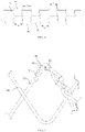
FIG. 1 is a schematic view of a covered stent under incomplete deployment in prior art; -
FIG. 2 is a structural schematic view of a covered stent of an embodiment of the present disclosure; -
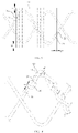
FIG. 3 is a schematic view of a first wave ring and wire heads structure of a covered stent of an embodiment of the present disclosure (the limiting unit is not shown); -
FIG. 4 is a structural schematic view of a first wave ring of a covered stent of an embodiment of the present disclosure; -
FIG. 5 is a structural schematic view of a first wave ring of a covered stent of an embodiment of the present disclosure when wire heads are not wound around wire rods; -
FIG. 6 is a structural schematic view of a first wave ring of a covered stent of an embodiment of the present disclosure; -
FIG. 7 is a schematic view of a first wave ring of an embodiment of the present disclosure when the surface of the first wave ring is provided with bumps or dimples; -
FIG. 8 is a structural schematic view of a first wave ring of an embodiment of the present disclosure when the surface of the first wave ring is provided with a roughening treatment; -
FIG. 9 is a schematic view of a first wave ring of a covered stent of an embodiment of the present disclosure when the first wave ring is provided with a covering unit (covering an area where wire heads and wire rods are wound); -
FIG. 10 is a schematic view of a first wave ring of a covered stent of an embodiment of the present disclosure when the first wave ring is provided with a covering unit (covering only an end of a wire head); -
FIG. 11 is a schematic diagram of the formation of a covering unit of a covered stent of an embodiment of the present disclosure; -
FIG. 12 is a schematic diagram of the effect of a covering unit of a covered stent of an embodiment of the present disclosure; -
FIG. 13 is a schematic view of a first wave ring of a covered stent of an embodiment of the present disclosure; and -
FIG. 14 is a schematic view of a first wave ring of a covered stent of an embodiment of the present disclosure. - Exemplary implementations of the present disclosure will be described in more detail below with reference to the accompanying drawings. Although the drawings show the exemplary implementations of the present disclosure, it should be understood that the present disclosure may be implemented in various forms and should not be limited to the implementations described herein. Instead, these implementations are provided such that the present disclosure can be understood more thoroughly, and can fully convey the scope of the present disclosure to those skilled in the art.
- It should be understood that the terms used herein are for the purpose of describing specific example implementations only, and are not intended to give any limitation. As used herein, the singular forms "a/an", "one" and "the" may also include plural forms, unless the context clearly indicates otherwise. The terms "comprise", "include", "contain" and "have" are inclusive, and indicate the existence of features, steps, operations, elements and/or components stated, but do not exclude the existence or addition of one or more other features, steps, operations, elements, components, and/or combinations thereof. The method steps, processes, and operations described herein are not to be construed as necessarily requiring them to be executed in the particular order described or illustrated, unless the order of execution is explicitly indicated. It should also be understood that additional or alternative steps may be used.
- Although the terms first, second, third, etc. may be used herein to describe a plurality of elements, components, regions, layers and/or sections, these elements, components, regions, layers and/or sections should not be limited by these terms. These terms may be used solely to distinguish one element, component, region, layer or section from another region, layer or section. The terms such as "first", "second", and other numerical terms are not used to imply an order or sequence herein unless it is clearly indicated in the context. Thus, a first element, component, region, layer or section discussed below could be termed a second element, component, region, layer or section without departing from the teachings of the example implementations.
- To facilitate description, spatially relative terms, such as "inside", "outside", "medial", "lateral", "under", "below", "over", "above", may be used herein to describe the relationship of an element or feature relative to another element or feature as illustrated. Such spatially relative terms are intended to encompass different orientations of the device in use or in operation in addition to the orientations depicted in the drawings. For example, if a device in a drawing is turned over, elements described as "under other elements or features" or "below other elements or features" would then be oriented as "over other elements or features" or "above other elements or features". Thus, the example term "below" can encompass both an orientation of above and below. The device may be oriented otherwise (rotated by 90 degrees or in other directions) and will be interpreted by the spatially relative descriptors used herein accordingly.
- In the field of interventional medical devices, especially for implants (such as stents) implanted in the body, the direction of blood inflow is defined as "proximal end" and the direction of blood outflow as "distal end", and the "proximal end" and "distal end" of any component of the medical device are defined according to this principle.
- As shown in
FIG. 2 , one of the embodiments of the present disclosure provides a coveredstent 100 including a plurality of W-shaped wave rings and a coveringfilm 10 through which the plurality of wave rings are connected. Specifically, the wave rings include afirst wave ring 20 provided on at least one end of the coveredstent 100 and asecond wave ring 30 arranged at intervals along the length of the coveredstent 100, and thefirst wave ring 20 is the one closest to the end of the covering film connected to the coveringfilm 10 on the coveredstent 100, i.e., if the first wave ring is provided on the proximal end of the covered stent, no other wave rings will be provided on the proximal end of the first wave ring. Thefirst wave ring 20 of the embodiment includes a double-layer W-shaped wave ring, and the "amplitude" of thefirst wave ring 20 is less than that of thesecond wave ring 30, and the wire diameter of the braided wires of thefirst wave ring 20 is also less than that of thesecond wave ring 30. Further, the coveringfilm 10 may be a material having good biocompatibility, such as PET (Polyethylene terephthalate) material, PTFE (Poly tetra fluoro ethylene ptfe) material, etc. - It should be understood that, in the present disclosure, the second wave ring is larger than the first wave ring in both wire diameter and amplitude, such that the first wave ring is softer than the second wave ring, and the first wave ring is provided on the end of the covered stent mainly in order to improve the adherence performance of the end of the covered stent and prevent the occurrence of endoleak.
- It will be appreciated that in other embodiments, the first wave ring may be provided with one ring or may be provided with multiple rings (i.e., a plurality of first wave rings are axially arranged); similarly, the first wave ring may be provided with a multi-layer W-shaped wave ring.
- Referring to
FIG. 3 , thefirst wave ring 20 of the embodiment is formed by braiding a single braided wire including wire heads 21 and awire rod 22, and the wire heads 21 of the braided wire are wound around thewire rod 22 adjacent to the wire heads 21. It will be appreciated that in other embodiments, the first wave ring may be formed by interweaving two braided wires, in which case the ends of the braided wires may be wound around the wire rods in the same manner as in this embodiment. - As shown in
FIG. 4 , the coveredstent 100 further includes limitingunit 40, and each of the limitingunit 40 is provided on thewire head 21 of the braided wire and thewire rod 22 adjacent to the wire head, and the limitingunit 40 limits the range of axial and radial movement of thewire head 21 relative to thewire rod 22. Since the movement of the wire heads 21 relative to thewire rods 22 along the wire heads is limited, the wire heads 21 wound around thewire rods 22 are not prone to becoming loose, which can enhance the structural stability of the first wave ring and is also conducive to preventing the wire heads 21 from tilting upwards, thereby protecting the coveringfilm 10 to a certain extent. - Further, each of the limiting
unit 40 may be a strip structure, which fixes thewire head 21 with thewire rod 22 in a spirally wound manner, and under the spiral winding of the strip component, thewire head 21 and thewire rod 22 are in close contact and exert pressure on each other, and when thewire head 21 has a movement trend relative to thewire rod 22, thewire head 21 will be simultaneously subjected to a double friction of both the limitingunit 40 and thewire rod 22, such that its axial and radial movement cannot easily occur, thereby preventing thewire head 21 from becoming loose. - And further, the strip component may be made of hot-melt material having a good biocompatibility, such as PTFE, and the strip structure made of the hot-melt material is bonded to the
wire rod 22 and thewire head 21 by means of heat treatment, thereby further reinforcing thewire head 21 and thewire rod 22 to ensure that thewire head 21 does not move axially and radially relative to thewire rod 22, which further eliminates the possibility of thewire head 21 becoming loose. - Still further, the limiting
unit 40 is spirally wound around thewire head 21 and thewire rod 22 to form a plurality of spiral sections, wherein one spiral section covers an end of thewire head 21, thereby preventing the end of thewire head 21 from moving in a direction away from thewire rod 22 which may result in the end tilting upwards, thus preventing the wire head from breaking thecovering film 10. In addition, in the process of spirally winding the strip structure, the winding is denser at a position closer to the end of thewire head 21, i.e., the spacing between the spiral sections gets smaller. In order to further ensure that the end of thewire head 21 will not be exposed from the gap between the spiral sections, the spacing L1 between the first spiral section and the second spiral section can be made less than the spacing L2 between the second spiral section and the third spiral section, and L2 can be made less than the diameter D of the wire rod 22 (i.e., the wire diameter of the braided wire), such that exposure of the end of thewire head 21 can be strictly avoided. - As shown in
FIG. 5 and FIG. 6 , another embodiment of the present disclosure provides a covered stent, which is substantially the same as the one in the first embodiment except for the structure of the limitingunit 40. -
FIG. 5 shows the structure of a first wave ring of the embodiment when wire heads are not wound, and specifically, the limitingunit 40 includes a plurality offirst projections 41 provided on thewire head 21 at intervals and a plurality ofsecond projections 42 provided on thewire rod 22 at intervals. Thefirst projections 41 and thesecond projections 42 are staggered along the length direction of the braided wire such that thefirst projections 41 and thesecond projections 42 can abut against each other when thewire head 21 has a trend to move axially along the wire head relative to thewire rod 22, thereby increasing the frictional force between thewire head 21 and thewire rod 22, thus avoiding thewire head 21 moving axially, and further preventing the loosening of thewire head 21, and the relative positions of thefirst projections 41 and thesecond projections 42 after winding the wire head and the wire rod can be seen inFIG. 6 . - It will be appreciated that the present disclosure is not limited to a specific number of the first projections and the second projections, but it should satisfy that both ends of at least one of the first projections can be blocked by the second projections. Or both ends of at least one of the second projections can be blocked by the first projections. That is, the limiting unit includes at least two first projections fixed on the wire head at intervals and at least one second projection fixed on the wire rod adjacent to the wire head, wherein the at least one second projection is located between the two first projections; or the limiting unit includes at least one first projection fixed on the wire head at intervals and at least two second projections fixed on the wire rod adjacent to the wire head, wherein the at least one first projection is located between the two second projections.
- It should be understood that the limiting
unit 40 of the embodiment is provided only on the portion of the braided wire close to the wire head and on the wire rod adjacent to the portion, and need not be provided for all the wire portions where the wire head and the wire rod are wound. - Further, the limiting
unit 40 of the embodiment may have a cylindrical structure, and end surfaces of the cylindrical structure may be relatively easily abutted against each other, thereby serving to increase frictional force between thewire head 21 and thewire rod 22. - Further, the spacing L3 between two adjacent
first projections 41 is greater than or equal to thelength 12 of thesecond projection 42 which refers to the dimension of thesecond projection 42 in axial direction of the wire rod, and less than or equal to 1.5 times thelength 12 of the second projection42. If the spacing between thefirst projections 41 is too small, thefirst projections 41 and thesecond projections 42 can only partially abut against or cannot abut against each other, which may result in that the effect of the friction between thewire head 21 and thewire rod 22 cannot be increased; instead, if the spacing between thefirst projections 41 is too large, when thefirst wave ring 20 is subjected to a force, thefirst projections 41 will move axially along with the wire head 21 a certain distance, so as to abut against thesecond projections 42, thereby increasing the frictional force between thewire head 21 and thewire rod 22, but at this time, thewire head 21 may have already damaged the coveringfilm 10 or the coveredstent 100. - Similarly, the spacing L4 between two adjacent
second projections 42 is greater than or equal to thelength 11 of thefirst projection 41 which refers to the dimension of thefirst projection 41 in axial direction of the wire head, and less than or equal to 1.5 times thelength 11 of thefirst projection 41. - Further, the limiting
units 40 of the embodiment are formed by winding a soft material (e.g. PTFE) on the braiding. Since the surface friction of the soft material is relatively high, it is advantageous to increase the frictional force between the wire heads 21 and thewire rods 22. In addition, it is also advantageous to reduce wear between thefirst projections 41 and thesecond projections 42. Specifically, the soft material will play a buffering role when thefirst projections 41 and thesecond projections 42 are brought into contact with each other, and therefore it is possible to prevent wear-out failure due to the material being excessively hard, and it is also advantageous to improve the service life of thefirst projections 41 and thesecond projections 42. It will be appreciated that in other embodiments the limiting units may be made of other materials having a lower stiffness than the braided wires, such as PET. And further, the soft material may be fixed to the braided wires by heat treatment. - Still further, as shown in
FIG. 7 , bumps or dimples are formed on the contact surfaces of the braided wires and the limitingunit 40 to increase frictional force. Specifically, especially when thefirst wave ring 20 is made of metal wires, it is difficult to fix thefirst projections 41 when they are disposed on the surface of the metal wires, and the frictional force and the connecting force between the metal wires and thefirst projections 41 are small, making that thefirst projections 41 are easily displaced from the wire heads 21, thereby causing the limiting function to fail. For this reason, bumps or dimples are provided on the contact surfaces of the wire heads 21 and thefirst projections 41, thereby increasing the contact area between the metal wires and thefirst projections 41, increasing the frictional force and the connecting force therebetween, to prevent thefirst projections 41 from being displaced relative to the wire heads 21. Similarly, the contact surfaces of thewire rods 22 and thesecond projections 42 are also provided with bumps or dimples for increasing the frictional force, thereby increasing the contact area between thewire rods 22 and thesecond projections 42, increasing the frictional force and connecting force therebetween, to prevent thesecond projections 42 from being displaced relative to thewire rods 22. - In other implementations, as shown in
FIG. 8 , roughening may also be applied to the surfaces of the braided wires to increase the friction between the braided wires and thefirst projections 41 and/or thesecond projections 42. Specifically, the length L5 of surface-treated portion of the braided wire should be less than the length of the correspondingfirst projections 41 or thelength 12 of the correspondingsecond projections 42. If the length of the surface-treated portion of the braided wire is too small, the frictional force and the connecting force are not increased, and if the length of the surface-treated portion is too large, a portion of treated braided wire will be easily exposed, resulting in a decrease in strength and corrosion resistance of the exposed portion, and further reducing the service life of thefirst wave ring 20. - Further, as shown in
FIG. 9- FIG. 12 , in other embodiments, the covered stent further includes a coveringunit 50 covering at least an end of thewire head 21. Since the coveringunit 50 covers the end of thewire head 21, even if thewire head 21 moves to some extent in axial or radial direction of the wire head, the end of thewire head 21 can be prevented from breaking the covering film and from catching the covering film, thereby protecting the covering film and the covered stent. - In some specific implementations, as shown in
FIG. 9 , the coveringunit 50 completely covers the area where wire heads 21 andwire rods 22 are wound, thereby limiting the range of movement of the wire heads 21 in the radial direction of the wire rods. The coveringunit 50 may be made of a material having pores smaller than the wire diameter of the braided wire as well as good biocompatibility and fracture-resistance, so as to prevent the ends of the wire heads 21 from penetrating out of the gaps of the coveringunit 50 or bursting the coveringunit 50, which may damage the coveringfilm 10. In addition, the spacing L6 between the edge of the coveringunit 50 and the wire heads 21 and the spacing L7 between the edge of the coveringunit 50 and the wave crest and wave trough of thefirst wave ring 20 need to be greater than 0.5 times the wire diameter of the braided wire, such that the coveringunit 50 can cooperate with the fixingstructure 40 to provide a certain axial movement space for the wire heads 21, and prevent the wire heads 21 of thefirst wave ring 20 from being tightly bound, which may, after the coveredstent 100 is assembled and compressed, cause stress concentration of thefirst wave ring 20, and then produce micro-cracks affecting the fatigue resistance performance of thefirst wave ring 20. - The covering
unit 50 of the embodiment may be fixed on thefirst wave ring 20 by heat treatment or may be fixed on the covering film by suture. When suture is adopted, the suture area of the coveringunit 50 is shown inFIG. 9 . The running direction of suture needle shall be parallel to the axis of the covered stent, and the suture spacing (the distance between two suture points between visible suture lines outside of covered stent) L8 shall be less than the wire diameter of braided wire, so as to avoid other components of the covered stent from hanging on the suture line of the coveringunit 50. - In other specific implementations, as shown in
FIG. 10 , the coveringunit 50 covers only the end of thewire head 21. Since the covered stent is assembled into a delivery sheath before it is delivered to the lesion site of the patient, in order to avoid that the coveringunit 50 affects the diameter of the delivery sheath required for the assembly of the covered stent (making the diameter of the delivery sheath larger), the coveringunit 50 is disposed only at the end of thewire head 21. Specifically, it is also possible to make the distance L9 between the edge of the coveringunit 50 and thewire head 21 greater than or equal to 0.5 times the wire diameter of the braided wire, thereby ensuring that the coveringunit 50 completely covers the end of thewire head 21 and providing a certain movement space for thewire head 21 to prevent the stress concentration of thefirst wave ring 20 after the covered stent is assembled and compressed due to over-tightening, which may result in a decrease in the fatigue resistance strength of thefirst wave ring 20. - In addition, the covering
unit 50 may also be a part of the covering film, and specifically, as shown inFIG. 11 , aprotrusion segment 11 may be integrally provided on the coveringfilm 10. When thefirst wave ring 20 is fixed on the coveringfilm 10, thewire head 21 of thefirst wave ring 20 has to be placed in the area covered by theprotrusion segment 11, and then theprotrusion segment 11 is folded to ensure that theprotrusion segment 11 can completely cover thewire end 21 or the area where thewire end 21 and thewire rod 22 are wound. Specifically, as shown inFIG. 12 , theprotrusion segment 11 for covering thewire head 21 may be cut independently during the process of manufacturing thecovering film 10, and since theprotrusion segment 11 has one side connected with the coveringfilm 10, there are relatively less sides required to be fastened later, thereby reducing the difficulty and time of disposing the coveringunit 50. - As shown in
FIG. 13 , another embodiment of the present disclosure provides a covered stent, which is substantially the same as the one in the second embodiment except for the structure of the limitingunit 40. - Specifically, the limiting
unit 40 is a structure formed by winding a strip material on thewire head 21 and thewire rod 22 successively in a staggered manner, and the structure is formed by winding the strip material from the beginning to the end, thereby saving time for disposing the limitingunit 40 and improving disposing efficiency. Also, since the limitingunit 40 is formed by winding a strip material on thewire head 21 and thewire rod 22 successively in a staggered manner, the limitingunit 40 connects thewire head 21 and thewire rod 22 together, thereby limiting the distance between thewire head 21 and thewire rod 22, thus limiting the range of radial movement of thewire head 21, facilitating disposing smaller limitingunit 40, and therefore reducing the diameter of the coveredstent 100 assembled into the sheath. In addition, when thewire head 21 of thefirst wave ring 20 moves, a certain backward pulling force is provided which may prevent thewire head 21 from moving further. - It will be appreciated that the limiting
unit 40 may be formed in the manner shown inFIG. 13 , i.e., by winding a strip material around the wire rod for one turn and then onto the same side of the wire head, winding around the wire head for one turn and then onto the same side of the wire rod, and so on, thus forming a staggered wound structure. The limitingunit 40 can also be formed in the manner shown inFIG. 14 , i.e., the strip material passes through the middle between the wire head and the wire rod, winds to the other side of the wire rod, wraps around the wire rod, and passes through the other side of the wire rod, passes through the middle between the wire head and the wire rod again to the other side of the wire head, and wraps around the wire head, and so on, thus forming a staggered wound structure. - The above descriptions are merely better specific implementations of the present disclosure, but the protection scope of the present disclosure is not limited thereto. Any skilled person who is familiar with this art could readily think of variations or substitutions within the disclosed technical scope of the present disclosure, and these variations or substitutions shall fall within the protection scope of the present disclosure. Therefore, the protection scope of the present disclosure shall be subjected to the protection scope of the claims.
Claims (10)
- A covered stent, comprising a first wave ring provided on at least one end of the covered stent, wherein the first wave ring is formed of braided wires by means of braiding, each of the braided wires has wire heads and a wire rod, with the wire heads being located at two ends of the wire rod, and the wire heads of the braided wire are wound around the adjacent wire rod, wherein that the covered stent further comprises a limiting unit, with the limiting unit being arranged on the wire head and the wire rod adjacent to the wire head, and the limiting unit limiting the range of axial and/or radial movement of the wire head relative to the wire rod.
- The covered stent of claim 1, wherein the limiting unit comprises a strip structure provided on the wire head and the wire rod adjacent to the wire head in a spirally wound manner.
- The covered stent of claim 2, wherein the strip structure is made of hot-melt material and is bonded to the wire rod and the wire head by means of heat treatment.
- The covered stent of claim 2, wherein a plurality of spiral sections are formed after the strip structure is spirally wound around the wire head and the wire rod, wherein at least one spiral section covers an end of the wire head, and a spacing between two spiral sections closest to the end of the wire head is less than a diameter of the wire rod.
- The covered stent of claim 1, wherein the limiting unit comprises at least two first projections provided on the wire head and at least one second projection provided on the wire rod adjacent to the wire head, the second projection being located between the two adjacent first projections; or the limiting unit comprises at least one first projection provided on the wire head and at least two second projections provided on the wire rod adjacent to the wire head, the first projection being located between the two adjacent second projections.
- The covered stent of claim 5, wherein a spacing between the two adjacent first projections is greater than or equal to the length of the second projection and less than or equal to 1.5 times the length of the second projection;
and/or a spacing between the two adjacent second projections is greater than or equal to the length of the first projection and less than or equal to 1.5 times the length of the first projection. - The covered stent of claim 1, wherein the limiting unit comprises a structure formed by winding a strip material on the wire head and the wire rod successively in a staggered manner.
- The covered stent of claims 1-7, wherein a contact surface between the braided wire and the limiting unit is provided with bumps or dimples, or the contact surface is roughened.
- The covered stent of claim 8, wherein the covered stent further comprises a covering unit covering at least the end of the wire head.
- The covered stent of claims 1-7, wherein that the covered stent further comprises a covering unit covering at least the end of the wire head.
Applications Claiming Priority (2)
| Application Number | Priority Date | Filing Date | Title |
|---|---|---|---|
| CN201911156626.0A CN112826632B (en) | 2019-11-22 | 2019-11-22 | Covered stent |
| PCT/CN2020/128299 WO2021098577A1 (en) | 2019-11-22 | 2020-11-12 | Covered stent |
Publications (2)
| Publication Number | Publication Date |
|---|---|
| EP4062870A1 true EP4062870A1 (en) | 2022-09-28 |
| EP4062870A4 EP4062870A4 (en) | 2023-12-27 |
Family
ID=75922641
Family Applications (1)
| Application Number | Title | Priority Date | Filing Date |
|---|---|---|---|
| EP20890425.0A Pending EP4062870A4 (en) | 2019-11-22 | 2020-11-12 | Covered stent |
Country Status (4)
| Country | Link |
|---|---|
| US (1) | US11918452B2 (en) |
| EP (1) | EP4062870A4 (en) |
| CN (1) | CN112826632B (en) |
| WO (1) | WO2021098577A1 (en) |
Families Citing this family (3)
| Publication number | Priority date | Publication date | Assignee | Title |
|---|---|---|---|---|
| US12070403B2 (en) * | 2020-07-06 | 2024-08-27 | Lifetech Scientific (Shenzhen) Co. Ltd. | Covered stent |
| CN113827370B (en) * | 2021-10-18 | 2024-08-16 | 广东迈迪健通科技有限公司 | Stent Graft |
| CN116407193B (en) * | 2021-12-30 | 2026-04-21 | 上海博畅医疗科技有限公司 | Braided supports and braided support systems |
Family Cites Families (26)
| Publication number | Priority date | Publication date | Assignee | Title |
|---|---|---|---|---|
| US6264684B1 (en) * | 1995-03-10 | 2001-07-24 | Impra, Inc., A Subsidiary Of C.R. Bard, Inc. | Helically supported graft |
| US6086611A (en) * | 1997-09-25 | 2000-07-11 | Ave Connaught | Bifurcated stent |
| US20010032010A1 (en) * | 1998-08-26 | 2001-10-18 | Thomas O. Hoover | Medical prosthesis |
| US6558418B2 (en) * | 1999-01-26 | 2003-05-06 | Edwards Lifesciences Corporation | Flexible heart valve |
| US7018401B1 (en) * | 1999-02-01 | 2006-03-28 | Board Of Regents, The University Of Texas System | Woven intravascular devices and methods for making the same and apparatus for delivery of the same |
| CN2427227Y (en) * | 2000-07-06 | 2001-04-25 | 中国人民解放军第二军医大学 | Novel blood vessel isolating system |
| US20040117004A1 (en) * | 2002-05-16 | 2004-06-17 | Osborne Thomas A. | Stent and method of forming a stent with integral barbs |
| CN2571401Y (en) * | 2002-08-20 | 2003-09-10 | 胡晓民 | Crossless support made of nickel-titanium memory alloy for medical use |
| CN2598483Y (en) * | 2003-01-17 | 2004-01-14 | 林亮 | Roasting net |
| CN2605866Y (en) * | 2003-02-11 | 2004-03-10 | 徐维华 | Canal stent |
| US20070196420A1 (en) * | 2006-02-17 | 2007-08-23 | Dwyer Clifford J | Fibers and yarns useful for constructing graft materials |
| WO2008051935A1 (en) * | 2006-10-22 | 2008-05-02 | Idev Technologies, Inc. | Methods for securing strand ends and the resulting devices |
| CN101172058B (en) * | 2006-10-31 | 2011-04-06 | 温宁 | Bracket valve with bracket and biovalve knitted integrally and preparation method thereof |
| US20100174300A1 (en) * | 2007-06-22 | 2010-07-08 | Phillip Nicolas Blondeel | Sutureless vessel anastomosis method and apparatus |
| GB2472603B (en) * | 2009-08-11 | 2011-12-14 | Cook Medical Technologies Llc | Implantable medical device |
| GB2472602B (en) | 2009-08-11 | 2011-12-14 | Cook Medical Technologies Llc | Medical device and method of manufacturing same |
| US9867725B2 (en) * | 2010-12-13 | 2018-01-16 | Microvention, Inc. | Stent |
| CN202508415U (en) * | 2012-01-05 | 2012-10-31 | 徐州海天石化有限公司 | Polypropylene woven bag |
| JP6425981B2 (en) * | 2014-11-26 | 2018-11-21 | 株式会社Pentas | Self-expanding stent |
| JP6549717B2 (en) * | 2015-01-12 | 2019-07-24 | マイクロベンション インコーポレイテッドMicrovention, Inc. | Stent |
| CN108095858B (en) | 2016-11-24 | 2020-08-21 | 先健科技(深圳)有限公司 | Anti-shortening covered stent and manufacturing method thereof |
| KR102613314B1 (en) * | 2017-02-03 | 2023-12-12 | 조리온 메디컬 인코포레이티드 | Wire-shaped bioabsorbable implant and assembly method |
| CN108742945A (en) * | 2018-05-11 | 2018-11-06 | 圆容生物医药无锡有限公司 | A kind of minimally invasive elevator belt of face, its moulding process and its working method |
| CN209107690U (en) | 2018-05-30 | 2019-07-16 | 杭州唯强医疗科技有限公司 | segmented stent graft |
| CN209392155U (en) | 2018-08-17 | 2019-09-17 | 先健科技(深圳)有限公司 | Stent Graft |
| CN110037839B (en) | 2019-05-28 | 2024-03-12 | 南微医学科技股份有限公司 | Intraluminal stent and preparation method thereof |
-
2019
- 2019-11-22 CN CN201911156626.0A patent/CN112826632B/en active Active
-
2020
- 2020-11-12 WO PCT/CN2020/128299 patent/WO2021098577A1/en not_active Ceased
- 2020-11-12 US US17/778,304 patent/US11918452B2/en active Active
- 2020-11-12 EP EP20890425.0A patent/EP4062870A4/en active Pending
Also Published As
| Publication number | Publication date |
|---|---|
| EP4062870A4 (en) | 2023-12-27 |
| CN112826632B (en) | 2022-06-21 |
| US11918452B2 (en) | 2024-03-05 |
| WO2021098577A1 (en) | 2021-05-27 |
| CN112826632A (en) | 2021-05-25 |
| US20230000613A1 (en) | 2023-01-05 |
Similar Documents
| Publication | Publication Date | Title |
|---|---|---|
| US11918452B2 (en) | Covered stent | |
| JP6764960B2 (en) | Stents and Catheter Stent Systems | |
| US12167957B2 (en) | Stent graft | |
| JP6248351B2 (en) | Closure plug with flat disk surface with variable angle | |
| CN109481109B (en) | Braided stent | |
| US10709588B2 (en) | Medical device and system having such a device | |
| CN107441615A (en) | Self-sealing tubular grafts, patches, and methods of making and using same | |
| US12070403B2 (en) | Covered stent | |
| CN115919504B (en) | Split type single embedded branch tectorial membrane support | |
| CN207400830U (en) | A kind of stent | |
| CN113081387B (en) | Covered stent, covered stent conveying system and covered stent loading method | |
| US11963893B2 (en) | Esophageal stents with helical thread | |
| CN118044915A (en) | Vascular stents and stent systems | |
| JP2024505308A (en) | Catheter reinforcement layer and catheter | |
| CN113040988A (en) | Blood vessel support | |
| CN110393607B (en) | stent graft | |
| CN211934141U (en) | intraluminal occluder | |
| CN212165963U (en) | Covered stent | |
| CN113893062A (en) | Covered stent | |
| CN119302783A (en) | Intraluminal implant, suturing method and vascular plug system | |
| CN116585082A (en) | Venous stent | |
| US20250312135A1 (en) | Airway Stent | |
| JP2012196498A (en) | Medical tube | |
| EP4458326A1 (en) | Endoluminal stent | |
| CN115737201B (en) | Mitral valve annulus device |
Legal Events
| Date | Code | Title | Description |
|---|---|---|---|
| STAA | Information on the status of an ep patent application or granted ep patent |
Free format text: STATUS: THE INTERNATIONAL PUBLICATION HAS BEEN MADE |
|
| PUAI | Public reference made under article 153(3) epc to a published international application that has entered the european phase |
Free format text: ORIGINAL CODE: 0009012 |
|
| STAA | Information on the status of an ep patent application or granted ep patent |
Free format text: STATUS: REQUEST FOR EXAMINATION WAS MADE |
|
| 17P | Request for examination filed |
Effective date: 20220607 |
|
| AK | Designated contracting states |
Kind code of ref document: A1 Designated state(s): AL AT BE BG CH CY CZ DE DK EE ES FI FR GB GR HR HU IE IS IT LI LT LU LV MC MK MT NL NO PL PT RO RS SE SI SK SM TR |
|
| DAV | Request for validation of the european patent (deleted) | ||
| DAX | Request for extension of the european patent (deleted) | ||
| A4 | Supplementary search report drawn up and despatched |
Effective date: 20231124 |
|
| RIC1 | Information provided on ipc code assigned before grant |
Ipc: A61F 2/07 20130101AFI20231121BHEP |
|
| RAP3 | Party data changed (applicant data changed or rights of an application transferred) |
Owner name: LIFETECH SCIENTIFIC (SHENZHEN) CO., LTD. |