EP4061563B1 - Process for manufacturing an aluminum alloy part - Google Patents
Process for manufacturing an aluminum alloy part Download PDFInfo
- Publication number
- EP4061563B1 EP4061563B1 EP20821332.2A EP20821332A EP4061563B1 EP 4061563 B1 EP4061563 B1 EP 4061563B1 EP 20821332 A EP20821332 A EP 20821332A EP 4061563 B1 EP4061563 B1 EP 4061563B1
- Authority
- EP
- European Patent Office
- Prior art keywords
- process according
- alloy
- optionally
- alloy elements
- laser
- Prior art date
- Legal status (The legal status is an assumption and is not a legal conclusion. Google has not performed a legal analysis and makes no representation as to the accuracy of the status listed.)
- Active
Links
- 238000004519 manufacturing process Methods 0.000 title claims description 53
- 238000000034 method Methods 0.000 title claims description 39
- 230000008569 process Effects 0.000 title claims description 34
- 229910000838 Al alloy Inorganic materials 0.000 title claims description 11
- 229910045601 alloy Inorganic materials 0.000 claims description 65
- 239000000956 alloy Substances 0.000 claims description 65
- 239000000654 additive Substances 0.000 claims description 34
- 230000000996 additive effect Effects 0.000 claims description 34
- 239000000843 powder Substances 0.000 claims description 26
- 239000000945 filler Substances 0.000 claims description 24
- 229910052751 metal Inorganic materials 0.000 claims description 20
- 239000002184 metal Substances 0.000 claims description 20
- 238000002844 melting Methods 0.000 claims description 17
- 230000008018 melting Effects 0.000 claims description 17
- 239000012535 impurity Substances 0.000 claims description 15
- 239000000463 material Substances 0.000 claims description 15
- 238000000151 deposition Methods 0.000 claims description 13
- 229910052782 aluminium Inorganic materials 0.000 claims description 10
- XAGFODPZIPBFFR-UHFFFAOYSA-N aluminium Chemical compound [Al] XAGFODPZIPBFFR-UHFFFAOYSA-N 0.000 claims description 10
- 230000015572 biosynthetic process Effects 0.000 claims description 10
- 229910052684 Cerium Inorganic materials 0.000 claims description 8
- 229910052779 Neodymium Inorganic materials 0.000 claims description 8
- 239000002245 particle Substances 0.000 claims description 8
- 238000010791 quenching Methods 0.000 claims description 8
- 230000000171 quenching effect Effects 0.000 claims description 8
- 229910001122 Mischmetal Inorganic materials 0.000 claims description 7
- 229910052769 Ytterbium Inorganic materials 0.000 claims description 7
- 229910052796 boron Inorganic materials 0.000 claims description 7
- 229910052791 calcium Inorganic materials 0.000 claims description 7
- 229910052804 chromium Inorganic materials 0.000 claims description 7
- 229910052735 hafnium Inorganic materials 0.000 claims description 7
- 229910052738 indium Inorganic materials 0.000 claims description 7
- 229910052750 molybdenum Inorganic materials 0.000 claims description 7
- 229910052758 niobium Inorganic materials 0.000 claims description 7
- 229910052698 phosphorus Inorganic materials 0.000 claims description 7
- 238000007711 solidification Methods 0.000 claims description 7
- 230000008023 solidification Effects 0.000 claims description 7
- 229910052712 strontium Inorganic materials 0.000 claims description 7
- 229910052721 tungsten Inorganic materials 0.000 claims description 7
- 229910052720 vanadium Inorganic materials 0.000 claims description 7
- 229910052759 nickel Inorganic materials 0.000 claims description 6
- 238000000137 annealing Methods 0.000 claims description 4
- 239000007787 solid Substances 0.000 claims description 4
- 229910052719 titanium Inorganic materials 0.000 claims description 3
- 238000007669 thermal treatment Methods 0.000 claims 4
- 230000032683 aging Effects 0.000 claims 1
- 230000035882 stress Effects 0.000 claims 1
- 238000010438 heat treatment Methods 0.000 description 19
- XEEYBQQBJWHFJM-UHFFFAOYSA-N Iron Chemical compound [Fe] XEEYBQQBJWHFJM-UHFFFAOYSA-N 0.000 description 15
- 238000005336 cracking Methods 0.000 description 12
- 230000008021 deposition Effects 0.000 description 12
- 238000005516 engineering process Methods 0.000 description 12
- 238000005260 corrosion Methods 0.000 description 10
- 230000007797 corrosion Effects 0.000 description 10
- 238000005245 sintering Methods 0.000 description 9
- 230000004927 fusion Effects 0.000 description 8
- 239000000203 mixture Substances 0.000 description 8
- 230000006835 compression Effects 0.000 description 6
- 238000007906 compression Methods 0.000 description 6
- 238000011282 treatment Methods 0.000 description 6
- 238000001465 metallisation Methods 0.000 description 5
- 238000004381 surface treatment Methods 0.000 description 5
- 238000003466 welding Methods 0.000 description 5
- 238000007743 anodising Methods 0.000 description 4
- 230000008901 benefit Effects 0.000 description 4
- 238000010891 electric arc Methods 0.000 description 4
- 238000010894 electron beam technology Methods 0.000 description 4
- 229910052742 iron Inorganic materials 0.000 description 4
- 238000003754 machining Methods 0.000 description 4
- 238000005498 polishing Methods 0.000 description 4
- 238000009864 tensile test Methods 0.000 description 4
- 238000005275 alloying Methods 0.000 description 3
- 239000004411 aluminium Substances 0.000 description 3
- 238000000149 argon plasma sintering Methods 0.000 description 3
- 238000000110 selective laser sintering Methods 0.000 description 3
- 230000035945 sensitivity Effects 0.000 description 3
- 238000007493 shaping process Methods 0.000 description 3
- 239000007921 spray Substances 0.000 description 3
- 238000005496 tempering Methods 0.000 description 3
- AZDRQVAHHNSJOQ-UHFFFAOYSA-N alumane Chemical group [AlH3] AZDRQVAHHNSJOQ-UHFFFAOYSA-N 0.000 description 2
- 238000004458 analytical method Methods 0.000 description 2
- 238000002048 anodisation reaction Methods 0.000 description 2
- 238000000889 atomisation Methods 0.000 description 2
- 239000011324 bead Substances 0.000 description 2
- 229910052729 chemical element Inorganic materials 0.000 description 2
- 239000011362 coarse particle Substances 0.000 description 2
- 238000007596 consolidation process Methods 0.000 description 2
- 229910052802 copper Inorganic materials 0.000 description 2
- 230000001186 cumulative effect Effects 0.000 description 2
- 238000010586 diagram Methods 0.000 description 2
- 230000000694 effects Effects 0.000 description 2
- 230000008020 evaporation Effects 0.000 description 2
- 238000001704 evaporation Methods 0.000 description 2
- 238000004372 laser cladding Methods 0.000 description 2
- 229910052749 magnesium Inorganic materials 0.000 description 2
- 229910052748 manganese Inorganic materials 0.000 description 2
- 230000003287 optical effect Effects 0.000 description 2
- 239000002244 precipitate Substances 0.000 description 2
- 230000001737 promoting effect Effects 0.000 description 2
- 238000010129 solution processing Methods 0.000 description 2
- 238000002490 spark plasma sintering Methods 0.000 description 2
- 238000003756 stirring Methods 0.000 description 2
- 229910052725 zinc Inorganic materials 0.000 description 2
- 229910052726 zirconium Inorganic materials 0.000 description 2
- 229910003407 AlSi10Mg Inorganic materials 0.000 description 1
- 229910052777 Praseodymium Inorganic materials 0.000 description 1
- 229910000676 Si alloy Inorganic materials 0.000 description 1
- QCWXUUIWCKQGHC-UHFFFAOYSA-N Zirconium Chemical compound [Zr] QCWXUUIWCKQGHC-UHFFFAOYSA-N 0.000 description 1
- 238000009825 accumulation Methods 0.000 description 1
- CSDREXVUYHZDNP-UHFFFAOYSA-N alumanylidynesilicon Chemical compound [Al].[Si] CSDREXVUYHZDNP-UHFFFAOYSA-N 0.000 description 1
- 229910052799 carbon Inorganic materials 0.000 description 1
- GWXLDORMOJMVQZ-UHFFFAOYSA-N cerium Chemical compound [Ce] GWXLDORMOJMVQZ-UHFFFAOYSA-N 0.000 description 1
- 230000001627 detrimental effect Effects 0.000 description 1
- 229910003460 diamond Inorganic materials 0.000 description 1
- 239000010432 diamond Substances 0.000 description 1
- 238000004090 dissolution Methods 0.000 description 1
- 229940082150 encore Drugs 0.000 description 1
- 238000001914 filtration Methods 0.000 description 1
- 229910052734 helium Inorganic materials 0.000 description 1
- 239000001307 helium Substances 0.000 description 1
- SWQJXJOGLNCZEY-UHFFFAOYSA-N helium atom Chemical compound [He] SWQJXJOGLNCZEY-UHFFFAOYSA-N 0.000 description 1
- 238000010191 image analysis Methods 0.000 description 1
- 230000006872 improvement Effects 0.000 description 1
- 238000009776 industrial production Methods 0.000 description 1
- 230000000977 initiatory effect Effects 0.000 description 1
- 230000003993 interaction Effects 0.000 description 1
- 229910052746 lanthanum Inorganic materials 0.000 description 1
- FZLIPJUXYLNCLC-UHFFFAOYSA-N lanthanum atom Chemical compound [La] FZLIPJUXYLNCLC-UHFFFAOYSA-N 0.000 description 1
- 239000007788 liquid Substances 0.000 description 1
- 239000000155 melt Substances 0.000 description 1
- QEFYFXOXNSNQGX-UHFFFAOYSA-N neodymium atom Chemical compound [Nd] QEFYFXOXNSNQGX-UHFFFAOYSA-N 0.000 description 1
- 238000000879 optical micrograph Methods 0.000 description 1
- PUDIUYLPXJFUGB-UHFFFAOYSA-N praseodymium atom Chemical compound [Pr] PUDIUYLPXJFUGB-UHFFFAOYSA-N 0.000 description 1
- 238000002360 preparation method Methods 0.000 description 1
- 239000000047 product Substances 0.000 description 1
- 238000001812 pycnometry Methods 0.000 description 1
- 238000007712 rapid solidification Methods 0.000 description 1
- 229910052706 scandium Inorganic materials 0.000 description 1
- 239000000126 substance Substances 0.000 description 1
- 238000004227 thermal cracking Methods 0.000 description 1
- 230000007704 transition Effects 0.000 description 1
- 229910052723 transition metal Inorganic materials 0.000 description 1
- 150000003624 transition metals Chemical class 0.000 description 1
- 230000002747 voluntary effect Effects 0.000 description 1
Images


Classifications
-
- B—PERFORMING OPERATIONS; TRANSPORTING
- B33—ADDITIVE MANUFACTURING TECHNOLOGY
- B33Y—ADDITIVE MANUFACTURING, i.e. MANUFACTURING OF THREE-DIMENSIONAL [3-D] OBJECTS BY ADDITIVE DEPOSITION, ADDITIVE AGGLOMERATION OR ADDITIVE LAYERING, e.g. BY 3-D PRINTING, STEREOLITHOGRAPHY OR SELECTIVE LASER SINTERING
- B33Y10/00—Processes of additive manufacturing
-
- C—CHEMISTRY; METALLURGY
- C22—METALLURGY; FERROUS OR NON-FERROUS ALLOYS; TREATMENT OF ALLOYS OR NON-FERROUS METALS
- C22C—ALLOYS
- C22C21/00—Alloys based on aluminium
- C22C21/06—Alloys based on aluminium with magnesium as the next major constituent
-
- B—PERFORMING OPERATIONS; TRANSPORTING
- B22—CASTING; POWDER METALLURGY
- B22F—WORKING METALLIC POWDER; MANUFACTURE OF ARTICLES FROM METALLIC POWDER; MAKING METALLIC POWDER; APPARATUS OR DEVICES SPECIALLY ADAPTED FOR METALLIC POWDER
- B22F10/00—Additive manufacturing of workpieces or articles from metallic powder
- B22F10/20—Direct sintering or melting
- B22F10/28—Powder bed fusion, e.g. selective laser melting [SLM] or electron beam melting [EBM]
-
- B—PERFORMING OPERATIONS; TRANSPORTING
- B23—MACHINE TOOLS; METAL-WORKING NOT OTHERWISE PROVIDED FOR
- B23K—SOLDERING OR UNSOLDERING; WELDING; CLADDING OR PLATING BY SOLDERING OR WELDING; CUTTING BY APPLYING HEAT LOCALLY, e.g. FLAME CUTTING; WORKING BY LASER BEAM
- B23K26/00—Working by laser beam, e.g. welding, cutting or boring
- B23K26/34—Laser welding for purposes other than joining
- B23K26/342—Build-up welding
-
- B—PERFORMING OPERATIONS; TRANSPORTING
- B33—ADDITIVE MANUFACTURING TECHNOLOGY
- B33Y—ADDITIVE MANUFACTURING, i.e. MANUFACTURING OF THREE-DIMENSIONAL [3-D] OBJECTS BY ADDITIVE DEPOSITION, ADDITIVE AGGLOMERATION OR ADDITIVE LAYERING, e.g. BY 3-D PRINTING, STEREOLITHOGRAPHY OR SELECTIVE LASER SINTERING
- B33Y40/00—Auxiliary operations or equipment, e.g. for material handling
- B33Y40/20—Post-treatment, e.g. curing, coating or polishing
-
- B—PERFORMING OPERATIONS; TRANSPORTING
- B33—ADDITIVE MANUFACTURING TECHNOLOGY
- B33Y—ADDITIVE MANUFACTURING, i.e. MANUFACTURING OF THREE-DIMENSIONAL [3-D] OBJECTS BY ADDITIVE DEPOSITION, ADDITIVE AGGLOMERATION OR ADDITIVE LAYERING, e.g. BY 3-D PRINTING, STEREOLITHOGRAPHY OR SELECTIVE LASER SINTERING
- B33Y70/00—Materials specially adapted for additive manufacturing
-
- B—PERFORMING OPERATIONS; TRANSPORTING
- B33—ADDITIVE MANUFACTURING TECHNOLOGY
- B33Y—ADDITIVE MANUFACTURING, i.e. MANUFACTURING OF THREE-DIMENSIONAL [3-D] OBJECTS BY ADDITIVE DEPOSITION, ADDITIVE AGGLOMERATION OR ADDITIVE LAYERING, e.g. BY 3-D PRINTING, STEREOLITHOGRAPHY OR SELECTIVE LASER SINTERING
- B33Y80/00—Products made by additive manufacturing
-
- C—CHEMISTRY; METALLURGY
- C22—METALLURGY; FERROUS OR NON-FERROUS ALLOYS; TREATMENT OF ALLOYS OR NON-FERROUS METALS
- C22C—ALLOYS
- C22C1/00—Making non-ferrous alloys
- C22C1/04—Making non-ferrous alloys by powder metallurgy
- C22C1/0408—Light metal alloys
- C22C1/0416—Aluminium-based alloys
-
- C—CHEMISTRY; METALLURGY
- C22—METALLURGY; FERROUS OR NON-FERROUS ALLOYS; TREATMENT OF ALLOYS OR NON-FERROUS METALS
- C22F—CHANGING THE PHYSICAL STRUCTURE OF NON-FERROUS METALS AND NON-FERROUS ALLOYS
- C22F1/00—Changing the physical structure of non-ferrous metals or alloys by heat treatment or by hot or cold working
- C22F1/002—Changing the physical structure of non-ferrous metals or alloys by heat treatment or by hot or cold working by rapid cooling or quenching; cooling agents used therefor
-
- C—CHEMISTRY; METALLURGY
- C22—METALLURGY; FERROUS OR NON-FERROUS ALLOYS; TREATMENT OF ALLOYS OR NON-FERROUS METALS
- C22F—CHANGING THE PHYSICAL STRUCTURE OF NON-FERROUS METALS AND NON-FERROUS ALLOYS
- C22F1/00—Changing the physical structure of non-ferrous metals or alloys by heat treatment or by hot or cold working
- C22F1/04—Changing the physical structure of non-ferrous metals or alloys by heat treatment or by hot or cold working of aluminium or alloys based thereon
- C22F1/047—Changing the physical structure of non-ferrous metals or alloys by heat treatment or by hot or cold working of aluminium or alloys based thereon of alloys with magnesium as the next major constituent
-
- B—PERFORMING OPERATIONS; TRANSPORTING
- B22—CASTING; POWDER METALLURGY
- B22F—WORKING METALLIC POWDER; MANUFACTURE OF ARTICLES FROM METALLIC POWDER; MAKING METALLIC POWDER; APPARATUS OR DEVICES SPECIALLY ADAPTED FOR METALLIC POWDER
- B22F2301/00—Metallic composition of the powder or its coating
- B22F2301/05—Light metals
- B22F2301/052—Aluminium
-
- Y—GENERAL TAGGING OF NEW TECHNOLOGICAL DEVELOPMENTS; GENERAL TAGGING OF CROSS-SECTIONAL TECHNOLOGIES SPANNING OVER SEVERAL SECTIONS OF THE IPC; TECHNICAL SUBJECTS COVERED BY FORMER USPC CROSS-REFERENCE ART COLLECTIONS [XRACs] AND DIGESTS
- Y02—TECHNOLOGIES OR APPLICATIONS FOR MITIGATION OR ADAPTATION AGAINST CLIMATE CHANGE
- Y02P—CLIMATE CHANGE MITIGATION TECHNOLOGIES IN THE PRODUCTION OR PROCESSING OF GOODS
- Y02P10/00—Technologies related to metal processing
- Y02P10/25—Process efficiency
Definitions
- the technical field of the invention is a process for manufacturing an aluminum alloy part, using an additive manufacturing technique.
- additive manufacturing techniques have developed. They consist of shaping a part by adding material, which is the opposite of machining techniques, which aim to remove material.
- machining techniques which aim to remove material.
- additive manufacturing is now operational to mass produce industrial products, including metal parts.
- additive manufacturing is defined according to the French standard XP E67-001 as a “set of processes allowing the manufacture, layer by layer, by adding material, of a physical object from a digital object”.
- ASTM F2792 January 2012 also defines additive manufacturing.
- Different additive manufacturing methods are also defined and described in the ISO/ASTM 17296-1 standard.
- the use of additive manufacturing to produce an aluminum part, with low porosity, was described in the document WO2015006447 .
- the application of successive layers is generally carried out by application of a so-called filler material, then melting or sintering of the filler material using an energy source such as a laser beam, electronic beam, plasma torch. or electric arc.
- the thickness of each added layer is of the order of a few tens or hundreds of microns.
- the mechanical properties of aluminum parts obtained by additive manufacturing depend on the alloy forming the filler metal, and more precisely on its composition as well as the heat treatments applied following the implementation of additive manufacturing.
- Aluminum silicon alloys type 4xxx, (Al-Si) possibly comprising Mg, are currently considered to be the most mature alloys for the application of the SLM process.
- this type of alloy can present some difficulties during anodizing.
- conductivity both thermal and electrical, is limited.
- the document WO2018185259 describes an alloy, intended to be used in the form of a powder, in an SLM type additive manufacturing process.
- the alloy may in particular contain from 2% to 7% by mass of Mg. It can also contain a mass fraction of Zr of 0 to 1%.
- the document US20180010216 describes an alloy intended to be used in the form of a powder, in an SLM type additive manufacturing process.
- the alloy may contain a mass fraction of Mg of 1% to 10%, and 0.45% to 3% of Zr. Note that this alloy does not contain iron.
- the document WO2018009359 describes an aluminum alloy, in powder form, comprising a mass fraction of Mg of 1 to 10%, as well as a mass fraction of Zr of 0.3 to 3%.
- the alloy can also contain Fe, Cu, but these elements are then present in the form of inevitable impurities, the content of which is less than 500 ppm.
- the inventors have determined an alloy composition which, used in an additive manufacturing process, makes it possible to obtain parts combining good mechanical properties, and in particular a good compromise between the elongation at break and the elastic limit.
- alloying elements include, for example, Cr, V, Ti, Mo, Ni, W, Nb, Ta, Sc, Hf, Nd, Ce, Co, La, Ag, Mn, Li, Y, Yb, Er , Sn, In, Si, Sb, Sr, Ba, Bi, Ca, P, B and/or mischmetal.
- the mass fraction of each other alloy element, taken individually, may be less than or equal to 1.0%, or even 500 ppm, or even 300 ppm, or even 200 ppm, or even 100 ppm.
- the composition of mischmetal is generally approximately 45 to 50% cerium, 25% lanthanum, 15 to 20% neodymium and 5% praseodymium.
- the alloy may be such that it does not contain Sc, except, possibly, in the impurity state.
- the mass fraction of Sc is preferably strictly less than 500 ppm.
- the alloy does not contain Mn, except, possibly, in the impurity state.
- the mass fraction of Mn is strictly less than 500 ppm.
- the alloy may be such that it does not contain Si, except, possibly, in the impurity state.
- the mass fraction of Si is preferably less than 0.2%, preferably less than 0.15%.
- the alloy is not an AA6xxx type alloy according to the Aluminum Association classification.
- Each layer can in particular describe a pattern defined from a digital model.
- the process may include, following the formation of the layers, an application of at least one heat treatment.
- the heat treatment can be or include relaxation, tempering or annealing, which can for example be carried out at a temperature preferably between 200°C and 500°C. It may also include solution processing and quenching. It may also feature hot isostatic compression.
- the process does not include heat treatment of the quenching type following the formation of the layers.
- the process does not include solution steps followed by quenching.
- the filler metal takes the form of a powder, exposure to a beam of light or charged particles results in localized melting followed by solidification, so as to form a solid layer.
- the filler metal comes from a filler wire, exposure to a heat source, such as for example an electric arc, results in localized melting followed by solidification. , so as to form a solid layer.
- a second object of the invention is a metal part, obtained after application of a process according to the first object of the invention from an alloy which does not contain Ti.
- the aluminum alloy forming the filler material may have any of the characteristics described in connection with the first subject of the invention.
- impurity we mean chemical elements present in the alloy unintentionally.
- the filler metal 15 is in the form of a powder placed on a support 10.
- An energy source in this case a laser source 11, emits a laser beam 12.
- the laser source is coupled to the material contribution by an optical system 13, the movement of which is determined according to a digital model M.
- the laser beam 12 propagates along a propagation axis Z, and follows a movement along an XY plane, describing a pattern depending on the model digital.
- the plane is for example perpendicular to the propagation axis Z.
- the interaction of the laser beam 12 with the powder 15 causes a selective melting of the latter, followed by solidification, resulting in the formation of a layer 20 1 . ..20 n .
- a layer has been formed, it is covered with powder of the filler metal and another layer is formed, superimposed on the layer previously made.
- the thickness of the powder forming a layer can for example be between 10 and 200 ⁇ m.
- Such a powder is particularly suitable for implementing an SLM type process. Such a process makes it possible to manufacture several monolithic parts in parallel, at a reasonable cost.
- the inventors have implemented an SLM-type additive manufacturing process to produce parts, for example intended for vehicles or aircraft. These parts must in particular have good mechanical properties, in particular from the point of view of the elastic limit or the elongation at break. They must also have low sensitivity to cracking.
- the distortion of the part is generally more significant as its dimensions increase.
- the advantage of an additive manufacturing process is precisely to obtain a part whose shape, after manufacturing, is definitive, or almost definitive. The occurrence of significant deformation resulting from heat treatment should therefore be avoided.
- finishing machining can be carried out on the part after its manufacture: the part manufactured by additive manufacturing extends according to its final shape, except for finishing machining.
- the inventors sought an alloy composition, forming the filler material for an additive manufacturing process, making it possible to obtain satisfactory mechanical properties, without requiring the application of heat treatments, subsequent to the formation of layers, risking distortion. This includes avoiding heat treatments involving a sudden variation in temperature.
- the invention makes it possible to obtain, by additive manufacturing, a part whose mechanical properties are satisfactory, in particular the mechanical tensile properties (elastic limit, elongation at break) as well as the sensitivity to cracking.
- the part resulting from the implementation of the process is compatible with electrochemical surface treatments, such as anodizing or electropolishing.
- the filler material can be in the form of a wire or a powder.
- composition of the alloy must also be compatible with the specificities of an additive manufacturing process.
- a mass fraction of Mg of 2.0% to 5.0% makes it possible to obtain satisfactory mechanical properties.
- the mass fraction of Mg is less than 3.5% or 3.0%, so as to limit the risks of intra-granular corrosion, in particular when exposing a manufactured part to temperatures of 60°C. at 200°C.
- the mass fraction of Mg is preferably between 2.0% and 3.5%, the optimal range being 2.0% to 3.0%.
- Below 2.0% it is considered that the mechanical properties are not sufficient: in fact, below 2.0%, we consider that there is an increased risk of cracking, particularly at the end of solidification.
- the mass fraction of Mg is optimized in order to obtain mechanical properties, while limiting the risks linked to corrosion.
- the mass fraction of Zr is thus sufficient to improve the mechanical properties, while conferring a sufficiently low liquidus temperature. This makes it possible to limit the temperature at which the powder is manufactured or when the additive manufacturing process is implemented.
- the alloy also includes a mass fraction of Fe of 0.6% to 3.0%, and preferably 0.8% to 1.5%. Such a mass fraction makes it possible to obtain good resistance to cracking. The presence of Fe also makes it possible to increase the elastic limit.
- the alloy may contain Zn, with a mass fraction less than or equal to 0.5%. This increases corrosion resistance.
- the alloy may contain Cu, with a mass fraction less than or equal to 0.5%. This increases corrosion resistance.
- the alloy may contain Zn and Cu, the cumulative mass fraction then being less than or equal to 0.5%.
- the aluminum alloy may also contain other alloying elements, such as for example Cr, V, Ti, Mo, W, Nb, Ta, Sc, Zn, Hf, Nd, Ce, Co, La, Ag , Li, Y, Yb, Er, Sn, In, Si, Sb, Sr, Ba, Bi, Ca, P, B and/or mischmetal, according to a cumulative mass fraction less than or equal to 4.0%, preferably less than or equal to 2.0%.
- the mass fraction of each other alloy element taken individually is less than or equal to 1.0%, preferably less than or equal to 0.5%.
- the mass fraction of Mn is strictly less than 500 ppm.
- the alloy does not contain Sc or Mn, or in low mass fractions, preferably less than 200 ppm or 100 ppm, or in the impurity state. , that is to say without voluntary addition.
- the alloy as previously described has good mechanical properties without it being necessary to apply post-manufacturing heat treatment.
- the application of a heat treatment, of the tempering or annealing type makes it possible to increase the elastic limit, to the detriment of the elongation at break.
- Test parts were produced by SLM, using an EOS 290 SLM type machine (EOS supplier).
- the laser power was 370 W.
- the scanning speed was 1250 mm/s.
- the distance between two adjacent scanning lines was 0.11 mm.
- Each layer of metal had a thickness of 60 ⁇ m.
- the tray on which the powder rested was heated to 200°C.
- the powder used had a particle size essentially ranging from 3 ⁇ m to 100 ⁇ m, with a median of 29 ⁇ m, a 10% fractile of 11 ⁇ m and a 90% fractile of 60 ⁇ m.
- the powder was formed from an alloy ingot using a Nanoval atomizer, at a temperature of 950°C and a pressure difference of 4 bar.
- the powder resulting from the atomization was filtered in size, the filtration size being 90 ⁇ m.
- the first test parts were produced, in the form of a cylinder with a diameter of 11 mm and a height of 46 mm.
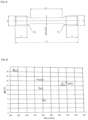
- the first test pieces, cylindrical, were machined to obtain cylindrical test specimens, intended for tensile tests, having dimensions listed in table 1.
- the geometry of the test specimens is represented on the Figure 3 .
- ⁇ represents the diameter of the central part of the test piece
- M the width of the two ends of the specimen
- LT the total length of the specimen
- R radius of curvature between the central part and the ends of the specimen
- Le length of the central part of the specimen
- F length of the two ends of the test piece.
- the values mentioned in table 1 are in millimeters. [Table 1] ⁇ M L.T. R THE F 4 8 45 3 22 8.7
- test specimens thus obtained were tested in tension at room temperature according to standard NF EN ISO 6892-1 (2009-10), in order to determine the elongation at break (A%) as well as the elastic limit Rp0.2. These properties were measured alongside the total length LT of each specimen.
- Table 2 brings together the results of the tensile tests obtained with the test specimens (test 1, test 2, test 3 and test 4). For each specimen, information was given on the heat treatment carried out, as well as the elongation at break (A% - unit %) and the elastic limit (RP0.2, unit: MPa). Prior to obtaining the test pieces, the first test pieces were subjected to stress relief for a period of 4 hours at 300°C.
- the first test parts from which the test specimens test 2, test 3 and test 4 were machined, underwent annealing at 400°C for durations respectively equal to 1 hour, 4 hours and 8 hours.
- the objective of the heat treatment at 400°C is to increase the elastic limit, by promoting the formation of Al 3 Zr precipitates.
- the elastic limit measured on the first test part is lower than the reference values. This is considered advantageous, as it is less conducive to the appearance of cracking. In fact, having a softer material makes it possible to limit residual stresses, the latter of which can lead to the appearance of cracking.
- Second test pieces were made, taking the form of cubes measuring 9 mm x 9 mm x 9 mm. These cubes were engraved to form grooves, of different diameters, intended to promote thermal cracking. Sections were formed, at mid-thickness, in order to assess the presence of cracking at the level of the slots, as well as the level of porosity. There Figure 5 shows the geometric characteristics of each section. Each cut was polished with abrasive paper and then finished with diamond paste up to 1 ⁇ m.
- Table 3 represents, for different cubes, the manufacturing parameters (power, vector deviation, scanning speed, deposition rate, usually designated by the term “built rate”), as well as the porosity (%).
- the latter was estimated by analysis of images of the sections, after polishing, using the free software “Image J”. Furthermore, microscopic analyzes carried out on each cut, after polishing, confirmed the absence of cracking at the level of the slots.
- the alloy proposed by the inventors therefore has low sensitivity to cracking.
- Figure 6 represents the images of 9 cuts after polishing.
- a remarkable result is the absence of cracking, while the deposition rate and scanning speed are high, and compatible with industrial production rates.
- the invention makes it possible to quickly manufacture parts, without them being affected by cracking. Furthermore, these results were observed by varying the manufacturing parameters, notably the scanning speed and the vector deviation. By using the alloy as previously described, it is not necessary to carry out a precise adjustment of the experimental parameters, to define optimal manufacturing parameters reducing cracking.
- the parts obtained from an alloy according to the invention are compatible with electrochemical surface treatment processes, such as anodizing or electropolishing. This is an important advantage compared to Al-Si type alloys, the latter being considered to be poorly compatible with such surface treatments, and in particular with electropolishing or anodizing.
- the alloy according to the invention then makes it possible to obtain parts with a good level of finish.
- a third test piece was produced, of parallelepiped shape, with dimensions 150 mm x 50 mm x 3 mm.
- the third test piece was electropolished.
- 3D surface profiles were produced before and after electropolishing, respectively, using a Brukers GT3D K1 optical microscope.
- THE Figures 7A and 7B show the 3D profiles obtained respectively before and after electropolishing. Each profile was made on a square surface with a side of 4 mm.
- the surface condition was characterized in particular by the following parameters: roughness Ra (average difference in roughness Ra according to the DIN NF EN ISO 4287 standard), roughness Rz (average profile height Rz according to the DIN NF EN ISO 4287 standard) and standard deviation ⁇ .
- the method may include hot isostatic compression (CIC).
- CIC hot isostatic compression
- the CIC treatment can in particular make it possible to improve the elongation properties and the fatigue properties. It can also help reduce porosity.
- Hot isostatic compression can be performed before, after or instead of heat treatment.
- the hot isostatic compression is carried out at a temperature of 250°C to 500°C and preferably from 300°C to 450°C, at a pressure of 500 to 3000 bars and for a duration of 0.5 to 100 hours.
- a solution can be carried out followed by quenching and tempering of the formed part and/or hot isostatic compression.
- Hot isostatic compression can in this case advantageously replace dissolution.
- the process according to the invention is advantageous, because it preferably does not require solution treatment followed by quenching.
- Solution processing can have a detrimental effect on mechanical strength by promoting coarsening of dispersoids or fine intermetallic phases.
- the method according to the present invention further optionally comprises a machining treatment, and/or a chemical, electrochemical or mechanical surface treatment, and/or a tribofinishing. These treatments can be carried out in particular to reduce roughness and/or improve corrosion resistance and/or improve resistance to fatigue crack initiation.
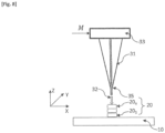
- An energy source 31 in this case a torch, forms an electric arc 32.
- the torch 31 is held by a welding robot 33.
- the part 20 to be manufactured is placed on a support 10.
- the manufactured part is a wall extending along a transverse axis Z perpendicular to a plane XY defined by the support 10.
- a filler wire 35 melts to form a weld bead.
- the welding robot is controlled by a digital model M.
- Each layer 20 1 ...20 n extends in the XY plane, according to a pattern defined by the digital model M.
- the diameter of the filler wire is preferably less than 3 mm. It can be from 0.5 mm to 3 mm and is preferably from 0.5 mm to 2 mm, or even from 1 mm to 2 mm. It is for example 1.2 mm.
Landscapes
- Chemical & Material Sciences (AREA)
- Engineering & Computer Science (AREA)
- Materials Engineering (AREA)
- Manufacturing & Machinery (AREA)
- Mechanical Engineering (AREA)
- Physics & Mathematics (AREA)
- Metallurgy (AREA)
- Organic Chemistry (AREA)
- Plasma & Fusion (AREA)
- Crystallography & Structural Chemistry (AREA)
- Thermal Sciences (AREA)
- Optics & Photonics (AREA)
- Powder Metallurgy (AREA)
- Laminated Bodies (AREA)
Description
Le domaine technique de l'invention est un procédé de fabrication d'une pièce en alliage d'aluminium, mettant en oeuvre une technique de fabrication additive.The technical field of the invention is a process for manufacturing an aluminum alloy part, using an additive manufacturing technique.
Depuis les années 80, les techniques de fabrication additive se sont développées. Elles consistent à mettre en forme une pièce par ajout de matière, ce qui est à l'opposé des techniques d'usinage, qui visent à enlever de la matière. Autrefois cantonnée au prototypage, la fabrication additive est à présent opérationnelle pour fabriquer des produits industriels en série, y compris des pièces métalliques.Since the 1980s, additive manufacturing techniques have developed. They consist of shaping a part by adding material, which is the opposite of machining techniques, which aim to remove material. Formerly confined to prototyping, additive manufacturing is now operational to mass produce industrial products, including metal parts.
Le terme « fabrication additive » est défini selon la norme française XP E67-001 comme un "ensemble des procédés permettant de fabriquer, couche par couche, par ajout de matière, un objet physique à partir d'un objet numérique". La norme ASTM F2792 (janvier 2012) définit également la fabrication additive. Différentes modalités de fabrication additive sont aussi définies et décrites dans la norme ISO/ASTM 17296-1. Le recours à une fabrication additive pour réaliser une pièce en aluminium, avec une faible porosité, a été décrit dans le document
D'autres méthodes de fabrication additive sont utilisables. Citons par exemple, et de façon non limitative, la fusion ou le frittage d'un matériau d'apport prenant la forme d'une poudre. Il peut s'agir de fusion ou de frittage laser. La demande de brevet
Les propriétés mécaniques des pièces d'aluminium obtenues par fabrication additive dépendent de l'alliage formant le métal d'apport, et plus précisément de sa composition ainsi que des traitements thermiques appliqués suite à la mise en oeuvre de la fabrication additive.The mechanical properties of aluminum parts obtained by additive manufacturing depend on the alloy forming the filler metal, and more precisely on its composition as well as the heat treatments applied following the implementation of additive manufacturing.
Les alliages d'aluminium au silicium, de type 4xxx, (Al-Si) comportant éventuellement Mg, sont actuellement considérés comme les alliages les plus mâtures pour l'application du procédé SLM. Cependant, ce type d'alliage peut présenter certaines difficultés lors de l'anodisation. De plus, la conductivité, aussi bien thermique qu'électrique, est limitée.Aluminum silicon alloys, type 4xxx, (Al-Si) possibly comprising Mg, are currently considered to be the most mature alloys for the application of the SLM process. However, this type of alloy can present some difficulties during anodizing. In addition, conductivity, both thermal and electrical, is limited.
Le document
Le document
Le document
Les inventeurs ont déterminé une composition d'alliage qui, utilisée dans un procédé de fabrication additive, permet d'obtenir des pièces associant de bonnes propriétés mécaniques, et notamment un bon compromis entre l'allongement à la rupture et la limite d'élasticité.The inventors have determined an alloy composition which, used in an additive manufacturing process, makes it possible to obtain parts combining good mechanical properties, and in particular a good compromise between the elongation at break and the elastic limit.
Un premier objet de l'invention est un procédé de fabrication d'une pièce comportant une formation de couches métalliques successives, superposées les unes aux autres, chaque couche étant formée par le dépôt d'un métal d'apport, le métal d'apport étant soumis à un apport d'énergie de façon à entrer en fusion et à constituer, en se solidifiant, ladite couche, le procédé étant caractérisé en ce que le métal d'apport est un alliage d'aluminium comportant les éléments d'alliage suivant (% en poids) :
- Mg : 2.0 % - 5.0 % ;
- Zr : 0.5%-1.0%;
- Fe : 0.6 % - 3.0 % ;
- éventuellement Zn : ≤ 0.5 % ;
- éventuellement Cu : ≤ 0.5 % ;
- autres éléments d'alliage au total ≤ 4.0 %, de préférence ≤ 2.0 %, et individuellement ≤ 1.0 %, de préférence ≤ 0.5 % ;
- impuretés : < 0.05 % individuellement, et au total < 0.15 % ;
- reste aluminium.
- Mg: 2.0% - 5.0%;
- Zr: 0.5%-1.0%;
- Fe: 0.6% - 3.0%;
- possibly Zn: ≤ 0.5%;
- possibly Cu: ≤ 0.5%;
- other alloying elements in total ≤ 4.0%, preferably ≤ 2.0%, and individually ≤ 1.0%, preferably ≤ 0.5%;
- impurities: < 0.05% individually, and in total <0.15%;
- remains aluminum.
Parmi les autres éléments d'alliage, citons par exemple Cr, V, Ti, Mo, Ni, W, Nb, Ta, Sc, Hf, Nd, Ce, Co, La, Ag, Mn, Li, Y, Yb, Er, Sn, In, Si, Sb, Sr, Ba, Bi, Ca, P, B et/ou du mischmétal. La fraction massique de chaque autre élément d'alliage, pris individuellement, peut être inférieure ou égal à 1.0 %, voire 500 ppm, voire à 300 ppm, voire à 200 ppm, voire à 100 ppm.Other alloying elements include, for example, Cr, V, Ti, Mo, Ni, W, Nb, Ta, Sc, Hf, Nd, Ce, Co, La, Ag, Mn, Li, Y, Yb, Er , Sn, In, Si, Sb, Sr, Ba, Bi, Ca, P, B and/or mischmetal. The mass fraction of each other alloy element, taken individually, may be less than or equal to 1.0%, or even 500 ppm, or even 300 ppm, or even 200 ppm, or even 100 ppm.
De manière connue de l'homme du métier, la composition du mischmétal est généralement d'environ 45 à 50 % de cérium, 25 % de lanthane, 15 à 20 % de néodyme et 5 % de praséodyme. L'alliage peut être tel qu'il ne comporte pas de Sc, sauf, éventuellement, à l'état d'impureté. Lorsque l'alliage comporte Sc, la fraction massique de Sc est de préférence strictement inférieure à 500 ppm.In a manner known to those skilled in the art, the composition of mischmetal is generally approximately 45 to 50% cerium, 25% lanthanum, 15 to 20% neodymium and 5% praseodymium. The alloy may be such that it does not contain Sc, except, possibly, in the impurity state. When the alloy contains Sc, the mass fraction of Sc is preferably strictly less than 500 ppm.
L'alliage ne comporte pas de Mn, sauf, éventuellement, à l'état d'impureté Lorsque l'alliage comporte Mn, la fraction massique de Mn est strictement inférieure à 500 ppm.The alloy does not contain Mn, except, possibly, in the impurity state. When the alloy contains Mn, the mass fraction of Mn is strictly less than 500 ppm.
L'alliage peut être tel qu'il ne comporte pas de Si, sauf, éventuellement, à l'état d'impureté. Lorsque l'alliage comporte Si, la fraction massique de Si est de préférence de moins de 0.2 %, préférentiellement de moins de 0.15 %.The alloy may be such that it does not contain Si, except, possibly, in the impurity state. When the alloy contains Si, the mass fraction of Si is preferably less than 0.2%, preferably less than 0.15%.
Selon une variante de la présente invention, l'alliage n'est pas un alliage de type AA6xxx selon la classification de l'Aluminum Association.According to a variant of the present invention, the alloy is not an AA6xxx type alloy according to the Aluminum Association classification.
Le procédé peut comporter les caractéristiques suivantes, prises isolément ou selon les combinaisons techniquement réalisables :
- Mg : 2.0 % - 3.5 % et de préférence Mg : 2.0 % - 3.0 % ;
- Zr : 0.6 % - 1.0 % et de préférence 0.7 % - 0.95 % ;
- Fe : 0.8 % - 1.5 %.
- Mg: 2.0% - 3.5% and preferably Mg: 2.0% - 3.0%;
- Zr: 0.6% - 1.0% and preferably 0.7% - 0.95%;
- Fe: 0.8% - 1.5%.
Chaque couche peut notamment décrire un motif défini à partir d'un modèle numérique.Each layer can in particular describe a pattern defined from a digital model.
Le procédé peut comporter, suite à la formation des couches, une application d'au moins un traitement thermique. Le traitement thermique peut être ou comporter une détente, un revenu ou un recuit, pouvant par exemple être effectué à une température préférentiellement comprise de 200°C à 500°C. Il peut également comporter une mise en solution et une trempe. Il peut également comporter une compression isostatique à chaud.The process may include, following the formation of the layers, an application of at least one heat treatment. The heat treatment can be or include relaxation, tempering or annealing, which can for example be carried out at a temperature preferably between 200°C and 500°C. It may also include solution processing and quenching. It may also feature hot isostatic compression.
Selon un mode de réalisation avantageux, le procédé ne comporte pas de traitement thermique de type trempe suite à la formation des couches. Ainsi, de préférence, le procédé ne comporte pas d'étapes de mise en solution suivie d'une trempe.According to an advantageous embodiment, the process does not include heat treatment of the quenching type following the formation of the layers. Thus, preferably, the process does not include solution steps followed by quenching.
Selon un mode de réalisation, le métal d'apport prend la forme d'une poudre, dont l'exposition à un faisceau de lumière ou de particules chargées résulte en une fusion localisée suivie d'une solidification, de façon à former une couche solide. Selon un autre mode de réalisation, le métal d'apport est issu d'un fil d'apport, dont l'exposition à une source de chaleur, telle que par exemple un arc électrique, résulte en une fusion localisée suivie d'une solidification, de façon à former une couche solide.According to one embodiment, the filler metal takes the form of a powder, exposure to a beam of light or charged particles results in localized melting followed by solidification, so as to form a solid layer. . According to another embodiment, the filler metal comes from a filler wire, exposure to a heat source, such as for example an electric arc, results in localized melting followed by solidification. , so as to form a solid layer.
Un deuxième objet de l'invention est une pièce métallique, obtenue après application d'un procédé selon le premier objet de l'invention à partir d'alliage qui ne comporte pas de Ti.A second object of the invention is a metal part, obtained after application of a process according to the first object of the invention from an alloy which does not contain Ti.
Un troisième objet de l'invention est un matériau, notamment sous la forme d'une poudre, destiné à être utilisé en tant que matériau d'apport d'un procédé de fabrication additive, caractérisé en ce qu'il est constitué d'un alliage d'aluminium, comportant les éléments d'alliage suivants (% en poids) :
- Mg: 2.0 % - 5.0 % ;
- Zr : 0.5 % - 1.0 % ;
- Fe : 0.6 % - 3.0 % ;
- éventuellement Zn : ≤ 0.5 % ;
- éventuellement Cu : ≤ 0.5 % ;
- autres éléments d'alliage au total ≤ 4.0 %, de préférence ≤ 2.0 %, et individuellement ≤ 1.0 %, de préférence ≤ 0.5 %, les autres éléments d'alliage étant choisis parmi: Cr, V, Mo, Ni, W, Nb, Ta, Sc, Hf, Nd, Ce, Co, La, Ag, Li, Y, Yb, Er, Sn, In, Si, Sb, Sr, Ba, Bi, Ca, P, B et/ou du mischmétal ;
- impuretés : < 0.05 % individuellement, et au total < 0.15 % ;
- reste aluminium.
- Mg: 2.0% - 5.0%;
- Zr: 0.5% - 1.0%;
- Fe: 0.6% - 3.0%;
- possibly Zn: ≤ 0.5%;
- possibly Cu: ≤ 0.5%;
- other alloy elements in total ≤ 4.0%, preferably ≤ 2.0%, and individually ≤ 1.0%, preferably ≤ 0.5%, the other alloy elements being chosen from: Cr, V, Mo, Ni, W, Nb , Ta, Sc, Hf, Nd, Ce, Co, La, Ag, Li, Y, Yb, Er, Sn, In, Si, Sb, Sr, Ba, Bi, Ca, P, B and/or mischmetal;
- impurities: < 0.05% individually, and in total <0.15%;
- remains aluminum.
L'alliage d'aluminium formant le matériau d'apport peut présenter l'une quelconque des caractéristiques décrites en lien avec le premier objet de l'invention.The aluminum alloy forming the filler material may have any of the characteristics described in connection with the first subject of the invention.
D'autres avantages et caractéristiques ressortiront plus clairement de la description qui va suivre de modes particuliers de réalisation de l'invention, donnés à titre d'exemples non limitatifs, et représentés sur les figures listées ci-dessous.Other advantages and characteristics will emerge more clearly from the following description of particular embodiments of the invention, given by way of non-limiting examples, and represented in the figures listed below.
-
[
Fig. 1 ] Lafigure 1 est un schéma illustrant un procédé de fabrication additive de type SLM. [Fig. 1 ] Therefigure 1 is a diagram illustrating an SLM type additive manufacturing process. -
[
Fig. 2 ] Lafigure 2 illustre l'évolution d'une température de liquidus en fonction de la fraction massique de Zirconium. [Fig. 2 ] Therefigure 2 illustrates the evolution of a liquidus temperature as a function of the mass fraction of Zirconium. -
[
Fig. 3 ] Lafigure 3 est une géométrie d'éprouvette de test utilisée pour effectuer des essais de traction, l'éprouvette de test étant obtenue à partir d'une première pièce de test. [Fig. 3 ] ThereFigure 3 is a test specimen geometry used to perform tensile tests, the test specimen being obtained from a first test piece. -
[
Fig. 4 ] Lafigure 4 représente les résultats d'essais de traction effectués sur des éprouvettes de test, élaborées avec un alliage selon l'invention, et des éprouvettes de références, élaborées avec un alliage de référence. [Fig. 4 ] ThereFigure 4 represents the results of tensile tests carried out on test specimens, produced with an alloy according to the invention, and reference specimens, produced with a reference alloy. -
[
Fig. 5 ] Lafigure 5 représente une coupe d'une deuxième pièce de test. [Fig. 5 ] ThereFigure 5 represents a section of a second test piece. -
[
Fig. 6 ] Lafigure 6 montre des images de coupes de deuxièmes pièces de test, après polissage, ces images étant utilisées pour quantifier un niveau de porosité. [Fig. 6 ] ThereFigure 6 shows images of sections of second test pieces, after polishing, these images being used to quantify a level of porosity. -
[
Fig. 7A ] Lafigure 7A est un profil surfacique tridimensionnel réalisé sur une troisième pièce de test avant électropolissage. [Fig. 7A ] ThereFigure 7A is a three-dimensional surface profile produced on a third test piece before electropolishing. -
[
Fig. 7B ] Lafigure 7B est un profil surfacique tridimensionnel réalisé sur une troisième pièce de test après électropolissage. [Fig. 7B ] ThereFigure 7B is a three-dimensional surface profile produced on a third test piece after electropolishing. -
[
Fig. 8 ] Lafigure 8 est un schéma illustrant un procédé de fabrication additive de type WAAM. [Fig. 8 ] Therefigure 8 is a diagram illustrating a WAAM type additive manufacturing process.
Dans la description, sauf indication contraire :
- la désignation des alliages d'aluminium est conforme à la nomenclature de The Aluminum Association ;
- les teneurs en éléments chimiques sont désignées en % et représentent des fractions massiques. La notation x % - y % signifie supérieur ou égal à x % et inférieur ou égal à y %.
- the designation of aluminum alloys conforms to the nomenclature of The Aluminum Association;
- the contents of chemical elements are designated in % and represent mass fractions. The notation x% - y% means greater than or equal to x% and less than or equal to y%.
Par impureté, on entend des éléments chimiques présents dans l'alliage de façon non intentionnelle.By impurity we mean chemical elements present in the alloy unintentionally.
La
La poudre peut présenter au moins l'une des caractéristiques suivantes :
- Taille moyenne de particules de 5 à 100 µm, de préférence de 5 à 25 µm, ou de 20 à 60 µm. Les valeurs données signifient qu'au moins 80 % des particules ont une taille dans la gamme spécifiée ;
- Forme sphérique. La sphéricité d'une poudre peut par exemple être déterminée en utilisant un morphogranulomètre ;
- Bonne coulabilité. La coulabilité d'une poudre peut par exemple être déterminée selon la norme ASTM B213 ou la norme ISO 4490 : 2018. Selon la norme ISO 4490 : 2018, le temps d'écoulement est de préférence inférieur à 50 ;
- Faible porosité, de préférence de 0 à 5 %, plus préférentiellement de 0 à 2 %, encore plus préférentiellement de 0 à 1 % en volume. La porosité peut notamment être déterminée par analyse d'images à partir de micrographies optiques ou par pycnométrie à l'hélium (voir la norme ASTM B923) ;
- Absence ou faible quantité (moins de 10 %, de préférence moins de 5 % en volume) de petites particules (1 à 20 % de la taille moyenne de la poudre), dites satellites, qui collent aux particules plus grosses.
- Average particle size of 5 to 100 µm, preferably 5 to 25 µm, or 20 to 60 µm. The values given mean that at least 80% of the particles have a size within the specified range;
- Spherical shape. The sphericity of a powder can for example be determined using a morphogranulometer;
- Good flowability. The flowability of a powder can for example be determined according to the ASTM B213 standard or the ISO 4490: 2018 standard. According to the ISO 4490: 2018 standard, the flow time is preferably less than 50;
- Low porosity, preferably 0 to 5%, more preferably 0 to 2%, even more preferably 0 to 1% by volume. The porosity can in particular be determined by image analysis from optical micrographs or by helium pycnometry (see standard ASTM B923);
- Absence or small quantity (less than 10%, preferably less than 5% by volume) of small particles (1 to 20% of the average size of the powder), called satellites, which stick to larger particles.
Une telle poudre est particulièrement adaptée à la mise en oeuvre d'un procédé de type SLM. Un tel procédé permet d'obtenir une fabrication, en parallèle, de plusieurs pièces monolithiques, et cela à un coût raisonnable.Such a powder is particularly suitable for implementing an SLM type process. Such a process makes it possible to manufacture several monolithic parts in parallel, at a reasonable cost.
Les inventeurs ont mis en oeuvre un procédé de fabrication additive de type SLM pour réaliser des pièces, par exemple destinées à des véhicules ou à des aéronefs. Ces pièces doivent en particulier disposer de bonnes propriétés mécaniques, en particulier du point de vue de la limite d'élasticité ou de l'allongement à la rupture. Elles doivent également présenter une faible sensibilité à la fissuration.The inventors have implemented an SLM-type additive manufacturing process to produce parts, for example intended for vehicles or aircraft. These parts must in particular have good mechanical properties, in particular from the point of view of the elastic limit or the elongation at break. They must also have low sensitivity to cracking.
Cependant, les inventeurs ont observé que l'application de traitements thermiques de type trempe pouvaient induire une distorsion de la pièce, du fait de la variation brutale de température. La distorsion de la pièce est généralement d'autant plus significative que ses dimensions sont importantes. Or, l'avantage d'un procédé de fabrication additive est précisément d'obtenir une pièce dont la forme, après fabrication est définitive, ou quasi-définitive. La survenue d'une déformation significative résultant d'un traitement thermique est donc à éviter. Par quasi-définitive, il est entendu qu'un usinage de finition peut être effectué sur la pièce après sa fabrication : la pièce fabriquée par fabrication additive s'étend selon sa forme définitive, à l'usinage de finition près.However, the inventors observed that the application of heat treatments such as quenching could induce distortion of the part, due to the sudden variation in temperature. The distortion of the part is generally more significant as its dimensions increase. However, the advantage of an additive manufacturing process is precisely to obtain a part whose shape, after manufacturing, is definitive, or almost definitive. The occurrence of significant deformation resulting from heat treatment should therefore be avoided. By quasi-final, it is understood that finishing machining can be carried out on the part after its manufacture: the part manufactured by additive manufacturing extends according to its final shape, except for finishing machining.
Ayant constaté ce qui précède, les inventeurs ont cherché une composition d'alliage, formant le matériau d'apport d'un procédé de fabrication additive, permettant d'obtenir des propriétés mécaniques satisfaisantes, sans nécessiter l'application de traitements thermiques, subséquents à la formation des couches, risquant d'induire une distorsion. Il s'agit notamment d'éviter les traitements thermiques impliquant une variation brutale de la température. Ainsi, l'invention permet d'obtenir, par fabrication additive, une pièce dont les propriétés mécaniques sont satisfaisantes, notamment les propriétés mécaniques de traction (limite d'élasticité, allongement à la rupture) ainsi que la sensibilité à la fissuration. De plus, la pièce résultant de la mise en oeuvre du procédé est compatible avec des traitements électrochimiques de surface, de type anodisation ou électropolissage.Having noted the above, the inventors sought an alloy composition, forming the filler material for an additive manufacturing process, making it possible to obtain satisfactory mechanical properties, without requiring the application of heat treatments, subsequent to the formation of layers, risking distortion. This includes avoiding heat treatments involving a sudden variation in temperature. Thus, the invention makes it possible to obtain, by additive manufacturing, a part whose mechanical properties are satisfactory, in particular the mechanical tensile properties (elastic limit, elongation at break) as well as the sensitivity to cracking. In addition, the part resulting from the implementation of the process is compatible with electrochemical surface treatments, such as anodizing or electropolishing.
En fonction du type de procédé de fabrication additive choisi, le matériau d'apport peut se présenter sous la forme d'un fil ou d'une poudre.Depending on the type of additive manufacturing process chosen, the filler material can be in the form of a wire or a powder.
La composition de l'alliage doit également être compatible avec les spécificités d'un procédé de fabrication additive. Il s'agit en particulier d'avoir une température de liquidus aussi basse que possible, de façon à limiter l'évaporation d'éléments présents dans l'alliage, en particulier Mg.The composition of the alloy must also be compatible with the specificities of an additive manufacturing process. In particular, it is a question of having a liquidus temperature as low as possible, so as to limit the evaporation of elements present in the alloy, in particular Mg.
Une fraction massique de Mg comprise de 2.0 % à 5.0 % permet d'obtenir des propriétés mécaniques satisfaisantes. De préférence, la fraction massique de Mg est inférieure à 3.5 % ou à 3.0 %, de façon à limiter les risques de corrosion intra-granulaire, en particulier lors de l'exposition d'une pièce fabriquée à des températures comprises de 60°C à 200°C. Afin d'obtenir une bonne résistance à la corrosion, il est donc préférable que la fraction massique de Mg soit de préférence comprise de 2.0 % à 3.5 %, la plage optimale étant de 2.0 % à 3.0 %. En dessous de 2.0 %, il est considéré que les propriétés mécaniques ne sont pas suffisantes : en effet, en dessous 2.0 %, on considère qu'il y a un risque accru de fissuration, en particulier en fin de solidification. Ainsi, la fraction massique de Mg est optimisée afin d'obtenir des propriétés mécaniques, tout en limitant les risques liés à la corrosion.A mass fraction of Mg of 2.0% to 5.0% makes it possible to obtain satisfactory mechanical properties. Preferably, the mass fraction of Mg is less than 3.5% or 3.0%, so as to limit the risks of intra-granular corrosion, in particular when exposing a manufactured part to temperatures of 60°C. at 200°C. In order to obtain good corrosion resistance, it is therefore preferable that the mass fraction of Mg is preferably between 2.0% and 3.5%, the optimal range being 2.0% to 3.0%. Below 2.0%, it is considered that the mechanical properties are not sufficient: in fact, below 2.0%, we consider that there is an increased risk of cracking, particularly at the end of solidification. Thus, the mass fraction of Mg is optimized in order to obtain mechanical properties, while limiting the risks linked to corrosion.
En outre, les inventeurs ont constaté qu'une faible fraction massique de Zr, comprise de 0.5 % à 1.0 %, et de préférence comprise de 0.7 % à 0.95 %, permet d'obtenir des propriétés mécaniques de traction satisfaisante, en particulier l'allongement à la rupture. En outre, la présence de Zr, couplé à un traitement thermique, permet d'améliorer la limite d'élasticité du fait de la formation de précipités Al3Zr. Une telle fraction massique de Zr permet de maintenir une température de liquidus relativement faible, en dessous de 1000°C. Cela permet de limiter l'évaporation d'éléments volatils, tels que Mg, lorsque l'alliage est soumis à une température supérieure ou égale à sa température de liquidus. Il s'agit notamment :
- de l'étape de préparation de la poudre, au cours de laquelle l'alliage fait l'objet d'une atomisation, de façon à former des gouttelettes d'alliage liquide. Ces dernières sont destinées à se solidifier pour former la poudre ;
- de la mise en oeuvre du procédé de fabrication proprement dit, au cours de laquelle l'alliage subit une fusion localisée sous l'effet de l'exposition au faisceau laser incident.
- of the powder preparation step, during which the alloy is atomized, so as to form droplets of liquid alloy. The latter are intended to solidify to form powder;
- of the implementation of the manufacturing process itself, during which the alloy undergoes localized melting under the effect of exposure to the incident laser beam.
La fraction massique de Zr est ainsi suffisante pour améliorer les propriétés mécaniques, tout en conférant une température de liquidus suffisamment faible. Cela permet de limiter la température de fabrication de la poudre ou de mise en oeuvre le procédé de fabrication additive.The mass fraction of Zr is thus sufficient to improve the mechanical properties, while conferring a sufficiently low liquidus temperature. This makes it possible to limit the temperature at which the powder is manufactured or when the additive manufacturing process is implemented.
La
L'alliage comporte également une fraction massique de Fe comprise de 0.6 % à 3.0 %, et de préférence de 0.8 % à 1.5 %. Une telle fraction massique permet d'obtenir une bonne résistance à la fissuration. La présence de Fe permet également d'augmenter la limite d'élasticité.The alloy also includes a mass fraction of Fe of 0.6% to 3.0%, and preferably 0.8% to 1.5%. Such a mass fraction makes it possible to obtain good resistance to cracking. The presence of Fe also makes it possible to increase the elastic limit.
De façon optionnelle, l'alliage peut comporter Zn, selon une fraction massique inférieure ou égale à 0.5 %. Cela permet d'augmenter la résistance à la corrosion.Optionally, the alloy may contain Zn, with a mass fraction less than or equal to 0.5%. This increases corrosion resistance.
De façon optionnelle, l'alliage peut comporter Cu, selon une fraction massique inférieure ou égale à 0.5 %. Cela permet d'augmenter la résistance à la corrosion.Optionally, the alloy may contain Cu, with a mass fraction less than or equal to 0.5%. This increases corrosion resistance.
L'alliage peut comporter Zn et Cu, la fraction massique cumulée étant alors inférieure ou égale à 0.5 %.The alloy may contain Zn and Cu, the cumulative mass fraction then being less than or equal to 0.5%.
L'alliage d'aluminium peut également comporter d'autres éléments d'alliage, tels que par exemple Cr, V, Ti, Mo, W, Nb, Ta, Sc, Zn, Hf, Nd, Ce, Co, La, Ag, Li, Y, Yb, Er, Sn, In, Si, Sb, Sr, Ba, Bi, Ca, P, B et/ou du mischmétal, selon une fraction massique cumulée inférieure ou égale à 4.0 %, de préférence inférieure ou égale à 2.0 %. La fraction massique de chaque autre élément d'alliage pris individuellement est inférieure ou égale à 1.0 %, de préférence inférieure ou égale à 0.5 % Lorsque l'alliage comporte Mn, la fraction massique de Mn est strictement inférieure à 500 ppm.The aluminum alloy may also contain other alloying elements, such as for example Cr, V, Ti, Mo, W, Nb, Ta, Sc, Zn, Hf, Nd, Ce, Co, La, Ag , Li, Y, Yb, Er, Sn, In, Si, Sb, Sr, Ba, Bi, Ca, P, B and/or mischmetal, according to a cumulative mass fraction less than or equal to 4.0%, preferably less than or equal to 2.0%. The mass fraction of each other alloy element taken individually is less than or equal to 1.0%, preferably less than or equal to 0.5%. When the alloy contains Mn, the mass fraction of Mn is strictly less than 500 ppm.
Parmi les éléments d'alliage précédemment listés, il est préférable que l'alliage ne comporte pas de Sc ou de Mn, ou selon des fractions massiques faibles, de préférence inférieures à 200 ppm ou 100 ppm, ou à l'état d'impureté, c'est-à-dire sans adjonction volontaire.Among the alloy elements previously listed, it is preferable that the alloy does not contain Sc or Mn, or in low mass fractions, preferably less than 200 ppm or 100 ppm, or in the impurity state. , that is to say without voluntary addition.
Outre de bonnes propriétés mécaniques, l'alliage tel que précédemment décrit comporte les avantages suivants :
- une composition pouvant être exempte de matériaux rares, par exemple Sc ou des terres rares ;
- une bonne résistance à la corrosion : en effet, il est considéré que les microstructures rapidement solidifiées et formées à partir d'alliages comportant une faible teneur en métaux de transition (en l'occurrence Zr et Fe) présentent une bonne résistance à la corrosion. Une cause possible est l'absence de grosses particules usuellement désignées "coarse particles" par l'homme du métier ;
- une bonne compatibilité avec des procédés électrochimiques de traitement de surface, en particulier l'anodisation, par l'absence, ou la faible quantité, de Si et la finesse de la microstructure formée suite à la solidification rapide de l'alliage.
- a composition which may be free of rare materials, for example Sc or rare earths;
- good corrosion resistance: in fact, it is considered that microstructures quickly solidified and formed from alloys containing a low content of transition metals (in this case Zr and Fe) have good corrosion resistance. A possible cause is the absence of large particles usually called "coarse particles" by those skilled in the art;
- good compatibility with electrochemical surface treatment processes, in particular anodization, by the absence, or small quantity, of Si and the fineness of the microstructure formed following the rapid solidification of the alloy.
Par ailleurs, l'alliage tel que précédemment décrit présente de bonnes propriétés mécaniques sans qu'il soit nécessaire d'appliquer un traitement thermique post-fabrication. Comme décrit par la suite, dans les exemples expérimentaux, l'application d'un traitement thermique, de type revenu ou recuit, permet d'augmenter la limite d'élasticité, au détriment de l'allongement à la rupture.Furthermore, the alloy as previously described has good mechanical properties without it being necessary to apply post-manufacturing heat treatment. As described below, in the experimental examples, the application of a heat treatment, of the tempering or annealing type, makes it possible to increase the elastic limit, to the detriment of the elongation at break.
Des premiers essais ont été réalisés en utilisant un alliage, dont la composition comportait, outre Al ; Mg : 2.7 % ; Zr : 0.76 % ; Fe : 1.0 % ; impuretés : < 0.05 % avec un cumul d'impuretés < 0.15 %. La température de liquidus d'un tel alliage a été estimée à 897°C. A titre de comparaison, un alliage de type Al ; Mg : 3,66 % ; Zr : 1,5 %, tel que décrit dans
Des pièces de test ont été réalisées par SLM, en utilisant une machine de type EOS 290 SLM (fournisseur EOS). La puissance du laser était de 370 W. La vitesse de balayage était de 1250 mm/s.Test parts were produced by SLM, using an EOS 290 SLM type machine (EOS supplier). The laser power was 370 W. The scanning speed was 1250 mm/s.
L'écart entre deux lignes adjacentes de balayage, usuellement désigné par le terme "écart vecteur", et usuellement désigné en anglais par le terme "hatch distance" était de 0.11 mm. Chaque couche de métal présentait une épaisseur de 60 µm. Le plateau sur lequel reposait la poudre a été chauffé à 200°C.The distance between two adjacent scanning lines, usually designated by the term "vector gap", and usually designated in English by the term "hatch distance" was 0.11 mm. Each layer of metal had a thickness of 60 µm. The tray on which the powder rested was heated to 200°C.
La poudre utilisée présentait une taille de particule essentiellement comprise de 3 µm à 100 µm, avec une médiane de 29 µm, un fractile à 10 % de 11 µm et un fractile à 90 % de 60 µm. La poudre a été formée à partir d'un lingot d'alliage en mettant en oeuvre un atomiseur Nanoval, à une température de 950°C et une différence de pression de 4 bar. La poudre résultant de l'atomisation a été filtrée en taille, la taille de filtration étant de 90 µm.The powder used had a particle size essentially ranging from 3 µm to 100 µm, with a median of 29 µm, a 10% fractile of 11 µm and a 90% fractile of 60 µm. The powder was formed from an alloy ingot using a Nanoval atomizer, at a temperature of 950°C and a pressure difference of 4 bar. The powder resulting from the atomization was filtered in size, the filtration size being 90 μm.
Des premières pièces de test ont été réalisées, sous la forme de cylindre de diamètre 11 mm et de hauteur 46 mm. Les premières pièces de test, cylindriques, ont été usinées pour obtenir des éprouvettes de test cylindriques, destinées à des essais de traction, ayant des dimensions listées dans le tableau 1. La géométrie des éprouvettes de test est représentée sur la
Les éprouvettes de test ainsi obtenues ont été testées en traction à température ambiante selon la norme NF EN ISO 6892-1 (2009-10), de façon à déterminer l'allongement à la rupture (A%) ainsi que la limite d'élasticité Rp0.2. Ces propriétés ont été mesurées parallèlement à la longueur totale LT de chaque éprouvette.The test specimens thus obtained were tested in tension at room temperature according to standard NF EN ISO 6892-1 (2009-10), in order to determine the elongation at break (A%) as well as the elastic limit Rp0.2. These properties were measured alongside the total length LT of each specimen.
Le tableau 2 rassemble les résultats des essais de traction obtenus avec les éprouvettes de test (test 1, test 2, test 3 et test 4). Pour chaque éprouvette, on a renseigné le traitement thermique effectué, ainsi que l'allongement à la rupture (A%- unité %) et la limite d'élasticité (RP0.2, unité : MPa). Préalablement à l'obtention des éprouvettes, les premières pièces de test ont fait l'objet d'une détente (stress relief) d'une durée de 4h à 300°C.Table 2 brings together the results of the tensile tests obtained with the test specimens (
Les premières pièces de test, à partir desquelles on a usiné les éprouvettes test 2, test 3 et test 4, ont subi un recuit à 400°C de durées respectivement égales à 1h, 4h et 8h. La première pièce de test, à partir de laquelle on a usiné l'éprouvette test 1 n'a pas subi de traitement thermique à la suite de la détente. L'objectif du traitement thermique à 400°C est d'augmenter la limite d'élasticité, en favorisant la formation de précipités Al3Zr.The first test parts, from which the
On a comparé les résultats obtenus avec des résultats de référence, obtenus en utilisant un alliage de type AlSi10Mg, ces résultats étant disponibles dans la bibliographie, et en particulier consultables sur le site internet de la société EOS Gmbh : https://gpiprototype.com/pdf/EOS_Aluminium_AlSi10Mg_en.pdf. Dans le tableau 2 ci-après, la référence "ref 1" correspond à une absence de traitement thermique, usuellement désigné par le terme "as built". La référence "ref 2" correspond à l'application d'une détente de 2h à 300°C.
Les résultats listés dans le tableau 2 sont illustrés sur la
Par ailleurs, on observe que sans traitement thermique ("as built"), la limite d'élasticité mesurée sur la première pièce de test est inférieure aux valeurs de référence. Ceci est considéré comme avantageux, car moins propice à l'apparition de fissurations. En effet, le fait de disposer d'un matériau plus mou permet de limiter les contraintes résiduelles, ces dernières pouvant entraîner l'apparition de fissurations.Furthermore, we observe that without heat treatment ("as built"), the elastic limit measured on the first test part is lower than the reference values. This is considered advantageous, as it is less conducive to the appearance of cracking. In fact, having a softer material makes it possible to limit residual stresses, the latter of which can lead to the appearance of cracking.
On observe qu'on obtient des propriétés mécaniques intéressantes, sans qu'il soit nécessaire d'effectuer un traitement de type mise en solution et trempe. Il est rappelé qu'il est préférable d'éviter un tel traitement, de façon à éviter une brusque variation de température, cette dernière pouvant induire une déformation de la pièce fabriquée.We observe that interesting mechanical properties are obtained, without it being necessary to carry out a treatment of the solution and quenching type. It is recalled that it is preferable to avoid such treatment, so as to avoid a sudden temperature variation, the latter of which could cause deformation of the manufactured part.
Des deuxièmes pièces de test ont été réalisées, prenant la forme de cubes de dimensions 9 mm x 9 mm x 9 mm. Ces cubes ont fait l'objet d'une gravure de façon à former des rainures, de différents diamètres, destinées à favoriser une fissuration thermique. Des coupes ont été formées, à mi-épaisseur, de façon à évaluer la présence de fissuration au niveau des fentes, ainsi que le niveau de porosité. La
La tableau 3 représente, pour différents cubes, les paramètres de fabrication (puissance, écart vecteur, vitesse de balayage, taux de déposition, usuellement désigné par le terme "built rate"), ainsi que la porosité (%). Cette dernière a été estimée par analyse d'images des coupes, après polissage, à l'aide du logiciel libre "Image J". Par ailleurs, des analyses au microscope effectuées sur chaque coupe, après polissage, ont confirmé l'absence de fissuration au niveau des fentes. L'alliage proposé par les inventeurs présente donc une faible sensibilité à la fissuration. La
Un résultat remarquable est l'absence de fissuration, alors que le taux de déposition et la vitesse de balayage sont élevés, et compatibles avec des cadences de production industrielles. L'invention permet de fabriquer rapidement des pièces, sans qu'elles soient affectées par des fissurations. Par ailleurs, ces résultats ont été observés en faisant varier les paramètres de fabrication, notamment la vitesse de balayage et l'écart vecteur. En utilisant l'alliage tel que précédemment décrit, il n'est pas nécessaire de procéder à un ajustement précis des paramètres expérimentaux, pour définir des paramètres optimaux de fabrication réduisant la fissuration.A remarkable result is the absence of cracking, while the deposition rate and scanning speed are high, and compatible with industrial production rates. The invention makes it possible to quickly manufacture parts, without them being affected by cracking. Furthermore, these results were observed by varying the manufacturing parameters, notably the scanning speed and the vector deviation. By using the alloy as previously described, it is not necessary to carry out a precise adjustment of the experimental parameters, to define optimal manufacturing parameters reducing cracking.
Les pièces obtenues à partir d'un alliage selon l'invention sont compatibles avec des procédés électrochimiques de traitement de surface, de type anodisation ou électropolissage. Il s'agit d'un avantage important en comparaison des alliages de type Al-Si, ces derniers étant considérés comme peu compatibles avec de tels traitements de surface, et en particulier avec l'électropolissage ou l'anodisation. L'alliage selon l'invention permet alors d'obtenir des pièces avec un bon niveau de finition.The parts obtained from an alloy according to the invention are compatible with electrochemical surface treatment processes, such as anodizing or electropolishing. This is an important advantage compared to Al-Si type alloys, the latter being considered to be poorly compatible with such surface treatments, and in particular with electropolishing or anodizing. The alloy according to the invention then makes it possible to obtain parts with a good level of finish.
On a réalisé une troisième pièce de test, de forme parallélépipédique, de dimensions 150 mm x 50 mm x 3 mm. La troisième pièce de test a fait l'objet d'un électropolissage. Des profils 3D de surface ont été réalisés respectivement avant et après l'électropolissage, en utilisant un microscope optique Brukers GT3D K1. Les
Le tableau 4 ci-après présente les résultats obtenus :
On observe que l'électropolissage permet une amélioration significative de l'état de surface.We observe that electropolishing allows a significant improvement in the surface condition.
Selon un mode de réalisation, le procédé peut comporter une compression isostatique à chaud (CIC). Le traitement CIC peut notamment permettre d'améliorer les propriétés d'allongement et les propriétés en fatigue. Il peut également permettre de réduire la porosité. La compression isostatique à chaud peut être réalisée avant, après ou à la place du traitement thermique. Avantageusement, la compression isostatique à chaud est réalisée à une température de 250°C à 500°C et de préférence de 300°C à 450°C, à une pression de 500 à 3000 bars et pendant une durée de 0,5 à 100 heures.According to one embodiment, the method may include hot isostatic compression (CIC). The CIC treatment can in particular make it possible to improve the elongation properties and the fatigue properties. It can also help reduce porosity. Hot isostatic compression can be performed before, after or instead of heat treatment. Advantageously, the hot isostatic compression is carried out at a temperature of 250°C to 500°C and preferably from 300°C to 450°C, at a pressure of 500 to 3000 bars and for a duration of 0.5 to 100 hours.
Selon un autre mode de réalisation, adapté aux alliages à durcissement structural, on peut réaliser une mise en solution suivie d'une trempe et d'un revenu de la pièce formée et/ou une compression isostatique à chaud. La compression isostatique à chaud peut dans ce cas avantageusement se substituer à la mise en solution.According to another embodiment, suitable for structurally hardening alloys, a solution can be carried out followed by quenching and tempering of the formed part and/or hot isostatic compression. Hot isostatic compression can in this case advantageously replace dissolution.
Cependant le procédé selon l'invention est avantageux, car il ne nécessite de préférence pas de traitement de mise en solution suivi de trempe. La mise en solution peut avoir un effet néfaste sur la résistance mécanique en favorisant un grossissement des dispersoïdes ou des phases intermétalliques fines.However, the process according to the invention is advantageous, because it preferably does not require solution treatment followed by quenching. Solution processing can have a detrimental effect on mechanical strength by promoting coarsening of dispersoids or fine intermetallic phases.
Selon un mode de réalisation, le procédé selon la présente invention comporte en outre optionnellement un traitement d'usinage, et/ou un traitement de surface chimique, électrochimique ou mécanique, et/ou une tribofinition. Ces traitements peuvent être réalisés notamment pour réduire la rugosité et/ou améliorer la résistance à la corrosion et/ou améliorer la résistance à l'initiation de fissures en fatigue.According to one embodiment, the method according to the present invention further optionally comprises a machining treatment, and/or a chemical, electrochemical or mechanical surface treatment, and/or a tribofinishing. These treatments can be carried out in particular to reduce roughness and/or improve corrosion resistance and/or improve resistance to fatigue crack initiation.
Optionnellement, il est possible de réaliser une déformation mécanique de la pièce, par exemple après la fabrication additive et/ou avant le traitement thermique.Optionally, it is possible to carry out mechanical deformation of the part, for example after additive manufacturing and/or before heat treatment.
Bien que décrit en lien avec une méthode de fabrication additive de type SLM, le procédé peut être appliqué à d'autres méthodes de fabrication additive de type WAAM, évoqué en lien avec l'art antérieur. La
Le diamètre du fil d'apport est de préférence inférieur à 3 mm. Il peut être compris de 0.5 mm à 3 mm et est de préférence compris de 0.5 mm à 2 mm, voire de 1 mm à 2 mm. Il est par exemple de 1.2 mm.The diameter of the filler wire is preferably less than 3 mm. It can be from 0.5 mm to 3 mm and is preferably from 0.5 mm to 2 mm, or even from 1 mm to 2 mm. It is for example 1.2 mm.
D'autres procédés sont par ailleurs envisageables, par exemple, et de façon non limitative :
- frittage sélectif par laser (Selective Laser Sintering ou SLS) ;
- frittage direct du métal par laser (Direct Metal Laser Sintering ou DMLS) ;
- frittage sélectif par chauffage (Selective Heat Sintering ou SHS) ;
- fusion par faisceau d'électrons (Electron Beam Melting ou EBM) ;
- dépôt par fusion laser (Laser Melting Deposition) ;
- dépôt direct par apport d'énergie (Direct Energy Déposition ou DED) ;
- dépôt direct de métal (Direct Metal Deposition ou DMD) ;
- dépôt direct par laser (Direct Laser Déposition ou DLD) ;
- technologie de dépôt par Laser (Laser Déposition Technology) ;
- ingénierie de formes nettes par laser (Laser Engineering Net Shaping) ;
- technologie de plaquage par laser (Laser Cladding Technology) ;
- technologie de fabrication de formes libres par laser (Laser Freeform Manufacturing Technology ou LFMT) ;
- dépôt par fusion laser (Laser Metal Deposition ou LMD) ;
- pulvérisation à froid (Cold Spray Consolidation ou CSC) ;
- fabrication additive par friction (Additive Friction Stir ou AFS) ;
- frittage par étincelle au plasma ou frittage flash (Field Assisted Sintering Technology, FAST ou spark plasma sintering) ; ou
- soudage par friction rotative (Inertia Rotary Friction Welding ou IRFW).
- selective laser sintering (Selective Laser Sintering or SLS);
- direct metal laser sintering (Direct Metal Laser Sintering or DMLS);
- selective heat sintering (SHS);
- electron beam melting (Electron Beam Melting or EBM);
- deposition by laser fusion (Laser Melting Deposition);
- direct deposit by energy contribution (Direct Energy Deposition or DED);
- direct metal deposition (Direct Metal Deposition or DMD);
- direct laser deposition (Direct Laser Deposition or DLD);
- Laser Deposition Technology;
- laser engineering net shaping;
- laser cladding technology;
- laser freeform manufacturing technology (Laser Freeform Manufacturing Technology or LFMT);
- deposition by laser fusion (Laser Metal Deposition or LMD);
- cold spray (Cold Spray Consolidation or CSC);
- additive manufacturing by friction (Additive Friction Stir or AFS);
- plasma spark sintering or flash sintering (Field Assisted Sintering Technology, FAST or spark plasma sintering); Or
- rotary friction welding (Inertia Rotary Friction Welding or IRFW).
Claims (14)
- Process for manufacturing a part (20) including a formation of successive metal layers (201...20n), which are superimposed on each other, each layer being formed by depositing a filler metal (15, 25), the filler metal being subjected to a supply of energy so as to become molten and to constitute, upon solidifying, said layer, the process being characterized in that the filler metal (15, 25) is an aluminum alloy not including Mn, unless optionally in the impurity state, and including the following alloy elements (% by weight);- Mg: 2.0% - 5.0%;- Zr: 0.5% - 1.0%;- Fe: 0.6% - 3.0%;- optionally Zn: ≤ 0.5%;- optionally Cu: ≤ 0.5%;- other alloy elements, in total ≤ 4%, and individually ≤ 1.0%, the other alloy elements being chosen from: Cr, V, Ti, Mo, Ni, W, Nb, Ta, Sc, Hf, Nd, Ce, Co, La, Ag, Li, Y, Yb, Er, Sn, In, Si, Sb, Sr, Ba, Bi, Ca, P, B and/or mischmetal;- impurities: < 0.05% individually, and in total < 0.15%;- remainder aluminum.
- Process according to any one of the preceding claims, wherein Mg: 2.0% - 3.5% or Mg: 2.0 % - 3.0 %.
- Process according to any one of the preceding claims, wherein Zr: 0.6% -1.0% and preferably Zr: 0.7% - 0.95%
- Process according to any one of the preceding claims, wherein Fe: 0.8% - 1.5%.
- Process according to any one of the preceding claims, not including Sc, unless optionally in the impurity state.
- Process according to any one of the preceding claims, wherein the individual mass fraction of each other alloy element is less than 500 ppm, or less than 300 ppm, or less than 200 ppm, or less than 100 ppm.
- Process according to any one of the preceding claims, including, following the formation of the layers (201...20n), an application of a thermal treatment.
- Process according to claim 7, wherein the thermal treatment is a stress relief or an aging or an annealing.
- Process according to any one of claims 7 or 8, wherein the thermal treatment is performed at a temperature from 200°C to 500°C.
- Process according to any one of the preceding claims, not including a quenching type thermal treatment following the formation of the layers.
- Process according to any one of the preceding claims, wherein the filler metal takes the form of a powder (15), the exposure of which to a light beam (12) or charged particles results in a localized melting followed by a solidification, so as to form a solid layer (201...20n).
- Process according to any one of claims 1 to 10, wherein the filler metal is obtained from a filler wire (25), the exposure of which to a heat source (22) results in a localized melting followed by a solidification, so as to form a solid layer (201...20n).
- Metal part obtained by a process according to any one of the preceding claims, wherein the other alloy elements are chosen from: Cr, V, Mo, Ni, W, Nb, Ta, Sc, Hf, Nd, Ce, Co, La, Ag, Li, Y, Yb, Er, Sn, In, Si, Sb, Sr, Ba, Bi, Ca, P, B and/or mischmetal.
- Powder, intended to be used as a filler material of an additive manufacturing process, characterized in that it is formed from an aluminum alloy, not including Mn, unless optionally in the impurity state, and including the following alloy elements (% by weight):- Mg: 2.0% - 5.0%;- Zr: 0.5% - 1.0%;- Fe: 0.6% - 3.0%;- optionally Zn: ≤ 0.5%;- optionally Cu: ≤ 0.5%;- other alloy elements, in total ≤ 4.0 %, and individually ≤ 1.0%, the other alloy elements being chosen from: Cr, V, Mo, Ni, W, Nb, Ta, Sc, Hf, Nd, Ce, Co, La, Ag, Li, Y, Yb, Er, Sn, In, Si, Sb, Sr, Ba, Bi, Ca, P, B and/or mischmetal;- impurities: < 0.05% individually, and in total < 0.15%;- remainder aluminum.
Applications Claiming Priority (2)
| Application Number | Priority Date | Filing Date | Title |
|---|---|---|---|
| FR1912915A FR3103123B1 (en) | 2019-11-19 | 2019-11-19 | Method of manufacturing an aluminum alloy part |
| PCT/FR2020/052107 WO2021099735A1 (en) | 2019-11-19 | 2020-11-18 | Process for manufacturing an aluminum alloy part |
Publications (2)
| Publication Number | Publication Date |
|---|---|
| EP4061563A1 EP4061563A1 (en) | 2022-09-28 |
| EP4061563B1 true EP4061563B1 (en) | 2024-01-03 |
Family
ID=69743389
Family Applications (1)
| Application Number | Title | Priority Date | Filing Date |
|---|---|---|---|
| EP20821332.2A Active EP4061563B1 (en) | 2019-11-19 | 2020-11-18 | Process for manufacturing an aluminum alloy part |
Country Status (6)
| Country | Link |
|---|---|
| US (1) | US20220389543A1 (en) |
| EP (1) | EP4061563B1 (en) |
| CN (1) | CN114728340B (en) |
| ES (1) | ES2975493T3 (en) |
| FR (1) | FR3103123B1 (en) |
| WO (1) | WO2021099735A1 (en) |
Families Citing this family (1)
| Publication number | Priority date | Publication date | Assignee | Title |
|---|---|---|---|---|
| CN116921699A (en) * | 2023-07-31 | 2023-10-24 | 连云港华鼎车轮有限公司 | Manufacturing process of lock ring for wheel type engineering machinery wheel |
Family Cites Families (21)
| Publication number | Priority date | Publication date | Assignee | Title |
|---|---|---|---|---|
| JP4998277B2 (en) * | 2007-01-22 | 2012-08-15 | 株式会社豊田中央研究所 | Aluminum alloy casting material and manufacturing method thereof, aluminum alloy material and manufacturing method thereof |
| JP5772731B2 (en) * | 2012-06-08 | 2015-09-02 | 株式会社豊田中央研究所 | Aluminum alloy powder forming method and aluminum alloy member |
| FR2998496B1 (en) * | 2012-11-27 | 2021-01-29 | Association Pour La Rech Et Le Developpement De Methodes Et Processus Industriels Armines | ADDITIVE MANUFACTURING PROCESS OF A PART BY SELECTIVE FUSION OR SELECTIVE SINTING OF BEDS OF POWDER WITH COMPACITY OPTIMIZED BY A HIGH ENERGY BEAM |
| US9296036B2 (en) | 2013-07-10 | 2016-03-29 | Alcoa Inc. | Methods for producing forged products and other worked products |
| US20170016096A1 (en) | 2015-07-16 | 2017-01-19 | Hamilton Sundstrand Corporation | Method of manufacturing aluminum alloy articles |
| FR3044682B1 (en) * | 2015-12-04 | 2018-01-12 | Constellium Issoire | LITHIUM COPPER ALUMINUM ALLOY WITH IMPROVED MECHANICAL RESISTANCE AND TENACITY |
| JP2017218609A (en) * | 2016-06-03 | 2017-12-14 | 株式会社豊田中央研究所 | Aluminum alloy-made high strength fastener and manufacturing method therefor |
| EP3481971A4 (en) | 2016-07-05 | 2019-12-25 | Nanoal LLC | Ribbons and powders from high strength corrosion resistant aluminum alloys |
| US11603583B2 (en) | 2016-07-05 | 2023-03-14 | NanoAL LLC | Ribbons and powders from high strength corrosion resistant aluminum alloys |
| CN106834837B (en) * | 2016-12-07 | 2018-08-03 | 中国航空工业集团公司北京航空材料研究院 | A kind of Al-Cu-Mg-Fe-Ni systems deformation thermostable aluminum alloy and preparation method thereof |
| US11674204B2 (en) * | 2017-02-01 | 2023-06-13 | Hrl Laboratories, Llc | Aluminum alloy feedstocks for additive manufacturing |
| US20190040503A1 (en) * | 2017-08-03 | 2019-02-07 | Hrl Laboratories, Llc | Feedstocks for additive manufacturing, and methods of using the same |
| WO2018185259A1 (en) | 2017-04-05 | 2018-10-11 | Amag Casting Gmbh | Starting material, use thereof, and additive manufacturing process using said starting material |
| FR3065178B1 (en) * | 2017-04-14 | 2022-04-29 | C Tec Constellium Tech Center | METHOD FOR MANUFACTURING AN ALUMINUM ALLOY PART |
| FR3066129B1 (en) * | 2017-05-12 | 2019-06-28 | C-Tec Constellium Technology Center | PROCESS FOR MANUFACTURING ALUMINUM ALLOY PIECE |
| US11192188B2 (en) * | 2017-05-26 | 2021-12-07 | Hamilton Sundstrand Corporation | Method of manufacturing aluminum alloy articles |
| FR3075827B1 (en) * | 2017-12-26 | 2022-04-01 | Thales Sa | ALUMINUM ALLOY POWDER FOR ADDITIVE MANUFACTURING, AND METHOD FOR MAKING A PART BY MANUFACTURING FROM THIS POWDER |
| FR3077524B1 (en) * | 2018-02-08 | 2021-01-15 | C Tec Constellium Tech Center | METHOD OF MANUFACTURING A PART FROM ALUMINUM AND CHROME ALLOY |
| US20190291182A1 (en) * | 2018-03-23 | 2019-09-26 | GM Global Technology Operations LLC | Aluminum alloy powders for powder bed fusion additive manufacturing processes |
| CN108486433B (en) * | 2018-06-11 | 2022-03-11 | 江苏科技大学 | Al-Mg-Sc-Zr series aluminum alloy composition for selective laser melting technology and preparation method of formed part |
| FR3083479B1 (en) * | 2018-07-09 | 2021-08-13 | C Tec Constellium Tech Center | METHOD OF MANUFACTURING AN ALUMINUM ALLOY PART |
-
2019
- 2019-11-19 FR FR1912915A patent/FR3103123B1/en active Active
-
2020
- 2020-11-18 ES ES20821332T patent/ES2975493T3/en active Active
- 2020-11-18 WO PCT/FR2020/052107 patent/WO2021099735A1/en unknown
- 2020-11-18 US US17/774,313 patent/US20220389543A1/en active Pending
- 2020-11-18 CN CN202080079963.9A patent/CN114728340B/en active Active
- 2020-11-18 EP EP20821332.2A patent/EP4061563B1/en active Active
Also Published As
| Publication number | Publication date |
|---|---|
| FR3103123A1 (en) | 2021-05-21 |
| US20220389543A1 (en) | 2022-12-08 |
| EP4061563A1 (en) | 2022-09-28 |
| WO2021099735A1 (en) | 2021-05-27 |
| CN114728340A (en) | 2022-07-08 |
| CN114728340B (en) | 2024-06-11 |
| ES2975493T3 (en) | 2024-07-08 |
| FR3103123B1 (en) | 2022-07-01 |
Similar Documents
| Publication | Publication Date | Title |
|---|---|---|
| EP3914746B1 (en) | Method for manufacturing an aluminum alloy part | |
| EP3853391B1 (en) | Process for the manufacture of a component made from an al-alloy | |
| EP3622095B1 (en) | Aluminum alloy part and process for manufacturing thereof | |
| EP3860788B1 (en) | Process for manufacturing an aluminum alloy part and an aluminium alloy powder | |
| WO2020165543A1 (en) | Process for manufacturing an aluminum alloy part | |
| EP3609641A1 (en) | Process for manufacturing an aluminum alloy part | |
| EP3860787B1 (en) | Process for manufacturing an aluminum alloy part | |
| EP3924123A1 (en) | Process for manufacturing an aluminum alloy part | |
| FR3077524A1 (en) | PROCESS FOR MANUFACTURING ALUMINUM ALLOY AND CHROME ALLOY | |
| EP4149702A2 (en) | Method for producing an aluminium alloy part | |
| EP4149703B1 (en) | Method for producing an aluminium alloy part | |
| EP4061563B1 (en) | Process for manufacturing an aluminum alloy part | |
| FR3082763A1 (en) | PROCESS FOR MANUFACTURING AN ALUMINUM ALLOY PART | |
| WO2020070453A1 (en) | Process for manufacturing an aluminium alloy part | |
| WO2020095009A2 (en) | Method for manufacturing an aluminum alloy part | |
| WO2022208037A1 (en) | Method for producing an aluminium alloy part implementing an additive manufacturing technique with preheating | |
| FR3136390A1 (en) | Process for manufacturing an aluminum alloy part | |
| FR3139018A1 (en) | Process for manufacturing an aluminum alloy part |
Legal Events
| Date | Code | Title | Description |
|---|---|---|---|
| STAA | Information on the status of an ep patent application or granted ep patent |
Free format text: STATUS: UNKNOWN |
|
| STAA | Information on the status of an ep patent application or granted ep patent |
Free format text: STATUS: THE INTERNATIONAL PUBLICATION HAS BEEN MADE |
|
| PUAI | Public reference made under article 153(3) epc to a published international application that has entered the european phase |
Free format text: ORIGINAL CODE: 0009012 |
|
| STAA | Information on the status of an ep patent application or granted ep patent |
Free format text: STATUS: REQUEST FOR EXAMINATION WAS MADE |
|
| 17P | Request for examination filed |
Effective date: 20220602 |
|
| AK | Designated contracting states |
Kind code of ref document: A1 Designated state(s): AL AT BE BG CH CY CZ DE DK EE ES FI FR GB GR HR HU IE IS IT LI LT LU LV MC MK MT NL NO PL PT RO RS SE SI SK SM TR |
|
| DAV | Request for validation of the european patent (deleted) | ||
| DAX | Request for extension of the european patent (deleted) | ||
| P01 | Opt-out of the competence of the unified patent court (upc) registered |
Effective date: 20230411 |
|
| GRAP | Despatch of communication of intention to grant a patent |
Free format text: ORIGINAL CODE: EPIDOSNIGR1 |
|
| STAA | Information on the status of an ep patent application or granted ep patent |
Free format text: STATUS: GRANT OF PATENT IS INTENDED |
|
| RIC1 | Information provided on ipc code assigned before grant |
Ipc: B22F 10/00 20210101ALI20230616BHEP Ipc: B33Y 10/00 20150101ALI20230616BHEP Ipc: B33Y 70/00 20200101ALI20230616BHEP Ipc: B33Y 80/00 20150101ALI20230616BHEP Ipc: C22C 1/04 20060101ALI20230616BHEP Ipc: C22C 21/06 20060101ALI20230616BHEP Ipc: B22F 3/105 20060101AFI20230616BHEP |
|
| INTG | Intention to grant announced |
Effective date: 20230704 |
|
| RIN1 | Information on inventor provided before grant (corrected) |
Inventor name: SHAHANI, RAVI Inventor name: ALTENBEREND, JOCHEN Inventor name: CHEHAB, BECHIR |
|
| GRAS | Grant fee paid |
Free format text: ORIGINAL CODE: EPIDOSNIGR3 |
|
| GRAA | (expected) grant |
Free format text: ORIGINAL CODE: 0009210 |
|
| STAA | Information on the status of an ep patent application or granted ep patent |
Free format text: STATUS: THE PATENT HAS BEEN GRANTED |
|
| AK | Designated contracting states |
Kind code of ref document: B1 Designated state(s): AL AT BE BG CH CY CZ DE DK EE ES FI FR GB GR HR HU IE IS IT LI LT LU LV MC MK MT NL NO PL PT RO RS SE SI SK SM TR |
|
| REG | Reference to a national code |
Ref country code: GB Ref legal event code: FG4D Free format text: NOT ENGLISH |
|
| REG | Reference to a national code |
Ref country code: CH Ref legal event code: EP |
|
| REG | Reference to a national code |
Ref country code: DE Ref legal event code: R096 Ref document number: 602020023989 Country of ref document: DE |
|
| REG | Reference to a national code |
Ref country code: IE Ref legal event code: FG4D Free format text: LANGUAGE OF EP DOCUMENT: FRENCH |
|
| REG | Reference to a national code |
Ref country code: NL Ref legal event code: FP |
|
| REG | Reference to a national code |
Ref country code: LT Ref legal event code: MG9D |
|
| REG | Reference to a national code |
Ref country code: AT Ref legal event code: UEP Ref document number: 1646303 Country of ref document: AT Kind code of ref document: T Effective date: 20240103 |
|
| PG25 | Lapsed in a contracting state [announced via postgrant information from national office to epo] |
Ref country code: IS Free format text: LAPSE BECAUSE OF FAILURE TO SUBMIT A TRANSLATION OF THE DESCRIPTION OR TO PAY THE FEE WITHIN THE PRESCRIBED TIME-LIMIT Effective date: 20240503 |
|
| REG | Reference to a national code |
Ref country code: ES Ref legal event code: FG2A Ref document number: 2975493 Country of ref document: ES Kind code of ref document: T3 Effective date: 20240708 |
|
| PG25 | Lapsed in a contracting state [announced via postgrant information from national office to epo] |
Ref country code: LT Free format text: LAPSE BECAUSE OF FAILURE TO SUBMIT A TRANSLATION OF THE DESCRIPTION OR TO PAY THE FEE WITHIN THE PRESCRIBED TIME-LIMIT Effective date: 20240103 |
|
| PG25 | Lapsed in a contracting state [announced via postgrant information from national office to epo] |
Ref country code: RS Free format text: LAPSE BECAUSE OF FAILURE TO SUBMIT A TRANSLATION OF THE DESCRIPTION OR TO PAY THE FEE WITHIN THE PRESCRIBED TIME-LIMIT Effective date: 20240403 Ref country code: HR Free format text: LAPSE BECAUSE OF FAILURE TO SUBMIT A TRANSLATION OF THE DESCRIPTION OR TO PAY THE FEE WITHIN THE PRESCRIBED TIME-LIMIT Effective date: 20240103 |
|
| PG25 | Lapsed in a contracting state [announced via postgrant information from national office to epo] |
Ref country code: CZ Free format text: LAPSE BECAUSE OF FAILURE TO SUBMIT A TRANSLATION OF THE DESCRIPTION OR TO PAY THE FEE WITHIN THE PRESCRIBED TIME-LIMIT Effective date: 20240103 |
|
| PG25 | Lapsed in a contracting state [announced via postgrant information from national office to epo] |
Ref country code: RS Free format text: LAPSE BECAUSE OF FAILURE TO SUBMIT A TRANSLATION OF THE DESCRIPTION OR TO PAY THE FEE WITHIN THE PRESCRIBED TIME-LIMIT Effective date: 20240403 Ref country code: NO Free format text: LAPSE BECAUSE OF FAILURE TO SUBMIT A TRANSLATION OF THE DESCRIPTION OR TO PAY THE FEE WITHIN THE PRESCRIBED TIME-LIMIT Effective date: 20240403 Ref country code: LT Free format text: LAPSE BECAUSE OF FAILURE TO SUBMIT A TRANSLATION OF THE DESCRIPTION OR TO PAY THE FEE WITHIN THE PRESCRIBED TIME-LIMIT Effective date: 20240103 Ref country code: IS Free format text: LAPSE BECAUSE OF FAILURE TO SUBMIT A TRANSLATION OF THE DESCRIPTION OR TO PAY THE FEE WITHIN THE PRESCRIBED TIME-LIMIT Effective date: 20240503 Ref country code: HR Free format text: LAPSE BECAUSE OF FAILURE TO SUBMIT A TRANSLATION OF THE DESCRIPTION OR TO PAY THE FEE WITHIN THE PRESCRIBED TIME-LIMIT Effective date: 20240103 Ref country code: CZ Free format text: LAPSE BECAUSE OF FAILURE TO SUBMIT A TRANSLATION OF THE DESCRIPTION OR TO PAY THE FEE WITHIN THE PRESCRIBED TIME-LIMIT Effective date: 20240103 Ref country code: BG Free format text: LAPSE BECAUSE OF FAILURE TO SUBMIT A TRANSLATION OF THE DESCRIPTION OR TO PAY THE FEE WITHIN THE PRESCRIBED TIME-LIMIT Effective date: 20240103 |
|
| PG25 | Lapsed in a contracting state [announced via postgrant information from national office to epo] |
Ref country code: PL Free format text: LAPSE BECAUSE OF FAILURE TO SUBMIT A TRANSLATION OF THE DESCRIPTION OR TO PAY THE FEE WITHIN THE PRESCRIBED TIME-LIMIT Effective date: 20240103 Ref country code: PT Free format text: LAPSE BECAUSE OF FAILURE TO SUBMIT A TRANSLATION OF THE DESCRIPTION OR TO PAY THE FEE WITHIN THE PRESCRIBED TIME-LIMIT Effective date: 20240503 |
|
| PG25 | Lapsed in a contracting state [announced via postgrant information from national office to epo] |
Ref country code: SE Free format text: LAPSE BECAUSE OF FAILURE TO SUBMIT A TRANSLATION OF THE DESCRIPTION OR TO PAY THE FEE WITHIN THE PRESCRIBED TIME-LIMIT Effective date: 20240103 Ref country code: PT Free format text: LAPSE BECAUSE OF FAILURE TO SUBMIT A TRANSLATION OF THE DESCRIPTION OR TO PAY THE FEE WITHIN THE PRESCRIBED TIME-LIMIT Effective date: 20240503 Ref country code: PL Free format text: LAPSE BECAUSE OF FAILURE TO SUBMIT A TRANSLATION OF THE DESCRIPTION OR TO PAY THE FEE WITHIN THE PRESCRIBED TIME-LIMIT Effective date: 20240103 Ref country code: LV Free format text: LAPSE BECAUSE OF FAILURE TO SUBMIT A TRANSLATION OF THE DESCRIPTION OR TO PAY THE FEE WITHIN THE PRESCRIBED TIME-LIMIT Effective date: 20240103 |