EP4061171B1 - Helmet and associated equipment - Google Patents
Helmet and associated equipment Download PDFInfo
- Publication number
- EP4061171B1 EP4061171B1 EP20804266.3A EP20804266A EP4061171B1 EP 4061171 B1 EP4061171 B1 EP 4061171B1 EP 20804266 A EP20804266 A EP 20804266A EP 4061171 B1 EP4061171 B1 EP 4061171B1
- Authority
- EP
- European Patent Office
- Prior art keywords
- attachment
- helmet
- net
- main body
- layer
- Prior art date
- Legal status (The legal status is an assumption and is not a legal conclusion. Google has not performed a legal analysis and makes no representation as to the accuracy of the status listed.)
- Active
Links
- 239000000463 material Substances 0.000 claims description 12
- 239000003733 fiber-reinforced composite Substances 0.000 description 3
- 239000002131 composite material Substances 0.000 description 2
- 239000000356 contaminant Substances 0.000 description 2
- 230000002093 peripheral effect Effects 0.000 description 2
- 239000004699 Ultra-high molecular weight polyethylene Substances 0.000 description 1
- 239000000853 adhesive Substances 0.000 description 1
- 230000001070 adhesive effect Effects 0.000 description 1
- XIWFQDBQMCDYJT-UHFFFAOYSA-M benzyl-dimethyl-tridecylazanium;chloride Chemical compound [Cl-].CCCCCCCCCCCCC[N+](C)(C)CC1=CC=CC=C1 XIWFQDBQMCDYJT-UHFFFAOYSA-M 0.000 description 1
- 239000004744 fabric Substances 0.000 description 1
- 239000000835 fiber Substances 0.000 description 1
- 238000003698 laser cutting Methods 0.000 description 1
- 238000004519 manufacturing process Methods 0.000 description 1
- 230000013011 mating Effects 0.000 description 1
- 239000002184 metal Substances 0.000 description 1
- 238000000034 method Methods 0.000 description 1
- 238000004080 punching Methods 0.000 description 1
- 230000000717 retained effect Effects 0.000 description 1
- 230000004083 survival effect Effects 0.000 description 1
- 229920000785 ultra high molecular weight polyethylene Polymers 0.000 description 1
- XLYOFNOQVPJJNP-UHFFFAOYSA-N water Substances O XLYOFNOQVPJJNP-UHFFFAOYSA-N 0.000 description 1
Images


Classifications
-
- A—HUMAN NECESSITIES
- A42—HEADWEAR
- A42B—HATS; HEAD COVERINGS
- A42B3/00—Helmets; Helmet covers ; Other protective head coverings
- A42B3/04—Parts, details or accessories of helmets
- A42B3/0406—Accessories for helmets
-
- A—HUMAN NECESSITIES
- A42—HEADWEAR
- A42B—HATS; HEAD COVERINGS
- A42B3/00—Helmets; Helmet covers ; Other protective head coverings
- A42B3/04—Parts, details or accessories of helmets
- A42B3/06—Impact-absorbing shells, e.g. of crash helmets
- A42B3/061—External coatings, e.g. with light reflective material
-
- A—HUMAN NECESSITIES
- A42—HEADWEAR
- A42B—HATS; HEAD COVERINGS
- A42B3/00—Helmets; Helmet covers ; Other protective head coverings
- A42B3/003—Helmet covers
-
- A—HUMAN NECESSITIES
- A42—HEADWEAR
- A42B—HATS; HEAD COVERINGS
- A42B3/00—Helmets; Helmet covers ; Other protective head coverings
- A42B3/04—Parts, details or accessories of helmets
-
- A—HUMAN NECESSITIES
- A42—HEADWEAR
- A42B—HATS; HEAD COVERINGS
- A42B3/00—Helmets; Helmet covers ; Other protective head coverings
- A42B3/04—Parts, details or accessories of helmets
- A42B3/06—Impact-absorbing shells, e.g. of crash helmets
- A42B3/062—Impact-absorbing shells, e.g. of crash helmets with reinforcing means
- A42B3/063—Impact-absorbing shells, e.g. of crash helmets with reinforcing means using layered structures
-
- A—HUMAN NECESSITIES
- A42—HEADWEAR
- A42B—HATS; HEAD COVERINGS
- A42B3/00—Helmets; Helmet covers ; Other protective head coverings
- A42B3/04—Parts, details or accessories of helmets
- A42B3/06—Impact-absorbing shells, e.g. of crash helmets
- A42B3/069—Impact-absorbing shells, e.g. of crash helmets with soft external layer, e.g. for use in impact sports
-
- F—MECHANICAL ENGINEERING; LIGHTING; HEATING; WEAPONS; BLASTING
- F41—WEAPONS
- F41H—ARMOUR; ARMOURED TURRETS; ARMOURED OR ARMED VEHICLES; MEANS OF ATTACK OR DEFENCE, e.g. CAMOUFLAGE, IN GENERAL
- F41H1/00—Personal protection gear
- F41H1/04—Protection helmets
Definitions
- the present invention relates to a helmet and associated equipment, such as attachment systems for helmet-borne equipment.
- Helmets have been known for a long time and come in various designs and configurations. Some helmets are designed for withstanding impacts. Some helmets, typically used by military personnel, are designed also with anti-ballistic function. While it was previously common to produce ballistic helmets with a metal layer, it is now common to produce a helmet main body in a lighter composite material. Typically, the main body of anti-ballistic helmets is made of a cured fiber reinforced composite, which provides a ballistic protection while having alight weight.
- an anti-ballistic helmet is given in publication US20100229271 , where the main body comprises monolayers of unidirectional ultrahigh molecular weight polyethylene fibers.
- helmets While the main object of helmets is to protect from impacts and in some cases to provide anti-ballistic function, helmets are also used to carry various types of equipment. Such equipment may include lights, cameras, communication devices, camouflage devices and more.
- Some helmets comprise a net that spans across the external face of the helmet main body. Such a helmet is described in GB 2474712 A that discloses the preamble of the independent claim 1.
- patches that are glued to the external face of the helmet which comprises one face of a hook-and-loop system, such as Velcro.
- the device comprises a compatible face of the hook-and-loop system, so that the device can be easily attached and removed.
- the company Core Survival presents an attachment patch for helmets, where the patch itself is attached to a net on the helmet, while the equipment itself is connected to the batch with a hook-and-loop system (Velcro).
- the patch comprises an attachment string that secures the equipment, such as a light-source, to the patch.
- the shroud is provided with a connection interface, to which compatible equipment can be securely attached.
- An object of the present invention may be to provide a helmet attachment system that provides advantages compared to the known solutions in the art.
- Another object may be to provide a helmet attachment system that reduces the risk of unintentional removal (loss) of attached equipment.
- an object may be to provide a helmet attachment system that is less exposed to wear during use.
- a helmet attachment arrangement that has a base layer and an attachment layer.
- the attachment layer is attached on one face of the base layer.
- the attachment layer comprises a plurality of attachment layer sections that have a mutual distance and that together define a string-receiving pattern.
- the helmet attachment arrangement can be attached between the main body of a helmet and a net attached to the main body.
- the string-receiving pattern comprises at least three pattern ports, through which strings of a net can enter and exit the string-receiving pattern.
- the string-receiving pattern can have four pattern ports.
- the attachment layer can comprise a part of a hook-and-loop attachment system.
- a hook-and-loop system is typically known and referred to as Velcro.
- Other attachment systems can however also be used, for instance snap buttons (typically used with raincoats and the like).
- the string-receiving pattern can be a strip-receiving pattern. It will then be configured to receive strips of a sheet net. The strips of a sheet net will exhibit a flat configuration with two opposite and parallel faces. Such a sheet net will be discussed in further detail below.
- the helmet attachment arrangement can comprise a flat portion configured to follow an external face of a helmet. Moreover, it can further comprise auxiliary attachment means that extend out from the flat portion.
- the auxiliary attachment means can be extensions of the attachment layer sections, which can be bent up / curve up from the shape of the flat portion and which can be folded around a piece of equipment.
- the auxiliary attachment means can also comprise a hook-and-loop system, a strap buckle, snap buttons, or other suitable attachment means that can attach two or more auxiliary attachment means together.
- a helmet having a helmet main body.
- the main body has a helmet edge that defines an aperture for reception of a user's head.
- the helmet further has a net that extends over or along the external surface of the main body.
- the net comprises strings that completely encircles net apertures.
- the net comprises less than 60, 40, or even less than 30 fully encircled net apertures. In some embodiments, the net comprises even less than 20 net apertures that are fully encircled by the net strings. Along the periphery of the net, there can advantageously be strings having free ends, which are attached to the helmet main body.
- the main body can be made of an anti-ballistic material.
- an anti-ballistic material can advantageously comprise a fiber-reinforced composite.
- Such a composite can in preferred embodiments be cured or consolidated during production of the helmet main body.
- the net can be a sheet net, which is made of a sheet material from which said net apertures are cut.
- sheet net is meant a net having strings in the form of strips that have a flat configuration, meaning that they have a parallel and substantially flat upper and lower face.
- the width of the strips will be larger than their height.
- the ratio between the width and the height of the strips can be at least 2:1, or even more preferably at least 4:1 or even 8:1.
- the helmet edge can be provided with an edge band that has a plurality of recesses.
- the net can comprise a plurality of free strings, the ends of which are attached to the helmet main body.
- the free strings can be attached to the helmet main body by means of attachment clamps.
- attachment clamps can in some embodiments be at least partially arranged in the recesses of the edge band.
- the attachment screws can extend through an attachment aperture that extends through the main body (i.e. through the wall of the main body).
- the attachment clamps which fasten free strings of the net to the main body, can be attached by the attachment screws.
- the net can in some embodiments be a sheet net.
- the attachment apertures can comprise strip-receiving apertures that have a straight edge against which the free strips of the net abut.
- the edge band further has inner recesses that are arranged on the internal side of the main body.
- the free strings or free strips of the net extend through the attachment apertures, and are clamped to the main body both by the attachment clamp and by an additional clamp, such as a counter screw head, on the opposite (i.e. inner) side of the main body.
- the said strip-receiving apertures can advantageously have a shape similar to the Greek capitol letter omega, i.e. like a circular aperture combined with a slit-shaped aperture at the periphery of the circular aperture.
- the helmet can in some embodiments have an edge band that comprises a wear indication means.
- the wear indication means can for instance comprise a wear indicator layer embedded in the edge band, behind a wear layer.
- the wear indication means can include a wear groove.
- the wear indication means comprises a wear groove
- the helmet can have a front attachment means that is attached to the front part of the main body by means of at least three screws.
- One screw can be an upper screw and two screws can be lower screws.
- the two lower screws can be arranged at least partly in a recess of an edge band arranged to the helmet edge.
- the two lower screws for connection of the front attachment means (typically referred to as a shroud) can be the same as two of the attachment screws used to attach the net, one only needs one additional screw to attach it with three screws.
- the net can be attached to the main body by means of attachment screws, and one or more wire attachment clips can be connected to the internal face of the main body by means of threaded nuts, by means of the heads of counter screws, or by means of discs.
- the disc can typically be retained in place by means of a nut or counter screw that engages with the attachment screw.
- a helmet attachment system that comprises a helmet, a net arranged on the helmet, and a helmet attachment arrangement as presented above and in one or more of the appending claims.
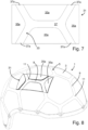
- Fig. 1a to Fig. 1d depict various helmets 1.
- the helmet 1 is a ballistic helmet.
- the skilled person will however appreciate that the discussed features also can be used on other types of helmets.
- the helmet 1 has a main body 3 that is made of an anti-ballistic material.
- the main body 3 can be made of a consolidated / cured fiber-reinforced composite material.
- the net is in the form of a sheet net 5, as the net is made of a sheet material.
- Other embodiments may involve another type of net, such as a net made of strings, strands or cords.
- the sheet net 5 can be made of a sheet material from which apertures 7 are cut, such as by laser cutting, punching or other methods.
- the sheet net 5 comprises said net apertures 7, which are at least partially defined by strips 9. Some of the net apertures 7 are completely defined (encircled) by the strips 9. The strips 9 extend between strip junctions 11. Some strips 9 extend between a strip junction 11 and an attachment section 13.
- all the strip junctions 11 comprises three strips 9 extending out from the strip junctions 11.
- some strip junctions 11 have four strips, while other junctions have three.
- strip junctions 11 can have even more strips 9.
- the helmet main body 3 comprises a helmet opening configured for receiving the head of a user.
- the helmet opening is defined by a helmet edge 15.
- the sheet net 5 is attached to the main body 3 of the helmet 1 along the extension of the edge band 17.
- the free ends of the peripheral strips 9 are attached. In this embodiment, the free ends of the peripheral strips 9 are attached with a screw and clamp arrangement.
- Fig. 2 depict an enlarged portion of the helmet 1 along a portion of the helmet edge 15. The head of an attachment screw 19 and an attachment clamp 21 is shown.
- the edge band 17 comprises a plurality of recesses 23 that receives the attachment clamps 21.
- the recesses 23 contributes in preventing the attachment sections 13 from getting entangled.
- the recesses 23 also provide some protection for the attachment sections 13, such as from impacts that may affect the attachment function.
- the sheet net 5 By fastening the sheet net 5 immediately adjacent the edge band 17, the sheet net 5 covers substantially the entire external face of the main body 3 (except for the exposed areas in the net apertures of course). Furthermore, one avoids extending the sheet net 5 around the helmet edge 15, where the sheet net 5 would be exposed to substantial wear.
- Fig. 3 shows another enlarged portion of the helmet main body 3 along a portion of the helmet edge 15.
- a strip 9 the attachment screw 19 and the attachment clamp 21 have been removed, making an attachment aperture 25 visible.
- Fig. 4 is an enlarged principle cross section through a portion of the main body 3 along the helmet edge 15, and through an attachment aperture 25.
- the attachment screw 19 extends through the attachment aperture 25 and is fastened with a threaded nut 19a in a conventional manner.
- other attachment solutions are also possible.
- the strip 9 is clamped between the attachment clamp 21 and the helmet main body 3, when the attachment screw 19 is tightened with the attachment nut 19a.
- the attachment aperture 25 comprises a strip-receiving section 25a and a screw-receiving section 25b.
- the strip-receiving section 25a and the screw-receiving section 25b together form one single aperture. In other embodiments, however, it is possible to form the strip-receiving section 25a and the screw-receiving section 25b are two distinct, adjacent apertures.
- the strip-receiving section 25a comprises a substantially straight edge, against which the strip 9 abuts when in a fastened stated.
- the cross-section of the edge band 17 has a generally U-shaped form.
- the U-form constitutes a channel in which the edge of the main body 3 is received.
- the U-shape thus has two parallel walls.
- the recesses 23 discussed above are in one of these parallel walls.
- Fig. 5 depicts another cross-section through an edge portion of the main body 3, showing again how the edge of the main body 3 is received in the edge band 17.
- Fig. 5 shows a wear indication means in the form of a wear indicator layer 17a that is a part of the edge band 17.
- the wear indicator layer 17a has another colour than the rest of the edge band 17.
- a wear layer 17b is arranged on the external side of the edge band 17, with respect to the wear indicator layer 17a.
- the wear layer 17a is of the same material as the other parts of the edge band 17, except for the wear indicator layer 17a.
- the wear indicator layer 17a and the wear layer 17b may be of the same material, however having a different colour to enable the wear indicating function.
- Fig. 1a and Fig. 1b there is indicated two wear-exposed portions 17c of the edge band 17, where the wear indicator layer 17a may be integrated in the edge band 17.
- a particular advantage with the wear indicator layer 17a is that by enabling indication of wear of the ballistic helmet 1, one can avoid that the edge of the main body 3 is exposed to water or other contaminants. Such contaminants could in some embodiments enter into the anti-ballistic material of the main body 3, and thus possibly reduce its anti-ballistic function.
- the edge band 17 can be attached to the helmet main body 3 by any suitable means, for instance with an adhesive.
- Fig. 6 depicts a helmet attachment arrangement 31 with a perspective view.
- the helmet attachment arrangement 31 has the form of a patch.
- the attachment arrangement 31 has a base layer 33.
- the base layer 33 can advantageously be made of a fabric, which makes the attachment arrangement 31 flexible. Attached to the base layer 33 there is an attachment layer 35. As shown in Fig. 6 , due to the thickness of the attachment layer 35, the upper face of the attachment layer 35 is elevated with respect to the upper face of the base layer 33.
- attachment layer sections 35a there are four attachment layer sections 35a.
- the attachment layer sections 35a are arranged on the base layer 33 with a mutual distance to each other, thereby forming a pattern.
- the pattern between the attachment layer sections 35a is a string-receiving pattern 37.
- the string-receiving pattern 37 is configured to receive strings or strips 9 of the sheet net 5 (cf. Fig. 1a ) when the attachment arrangement 31 is interposed between the helmet main body 3 and the sheet net 5. This is shown with the perspective view of Fig. 8 .
- As the string-receiving pattern 37 in this embodiment is configured to receive strips 9 of the net 5, which is a sheet net 5, it may be termed a strip-receiving pattern 37.
- Fig. 7 is a top view of the helmet attachment arrangement 31.
- the strip-receiving pattern 37 is configured to receive two strip junctions 11 that each connects three strips 9.
- the two strip junctions 11 are interconnected with a common strip 9.
- Four strips exit the strip-receiving pattern 37 through four pattern ports 37a.
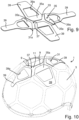
- Fig. 8 shows the helmet attachment arrangement 31 when placed between the helmet main body 3 and the sheet net 5, with the strip-receiving pattern 37 aligned with the sheet net 5.
- the engagement between the edges of the attachment layer sections 35a, which define the strip-receiving pattern 37, and the sheet net 5, will secure the attachment arrangement 31 to the ballistic helmet 1.
- the upper face of the attachment layer 35 can comprise one part of a hook-and-loop system, such as the system often referred to as Velcro.
- equipment that shall be attached to the ballistic helmet 1 can be fastened simply by placing the equipment onto the attachment arrangement 31 on the helmet (provided of course that the equipment is provided with a mating part of the hook-and-loop system).
- the attachment layer 35 can comprise other attachment means, for instance snap-buttons / snap fasteners.
- the entire attachment arrangement 31 had a substantially flat configuration when mounted to the ballistic helmet 1.
- the shown attachment arrangement 31 constitutes a flat portion 31a.
- the attachment arrangement 31 depicted in Fig. 9 has a flat portion 31a and is further provided with auxiliary attachment means 39 that extend out from the flat portion 31a.
- the flat portion 31a corresponds to the attachment arrangement 31 shown in Fig. 6 to Fig. 8 .
- the auxiliary attachment means 39 are in the form of flexible attachment flaps. As appears from Fig. 9 and from Fig. 10 , the auxiliary attachment means 39 are configured as extensions of the attachment layer sections 35a beyond the flat portion 31a.
- the auxiliary attachment means 39 can be bent upwards from the surface of the helmet main body 3, to envelop a piece of equipment. This is shown in Fig. 11 , where equipment 101 in the form of a portable light is attached to the helmet attachment arrangement 31. As will be understood, before attaching the portable equipment 101, the attachment arrangement 31 was attached to the ballistic helmet 1.
- the auxiliary attachment means 39 are also provided with a hook-and-loop system.
- opposite auxiliary attachment means 39 such as attachment flaps 39 provided on opposite sides of the flat portion 31a, can connect to each other when being folded over the portable equipment 101.
- Other solutions for connecting the auxiliary attachment means together can also be used, for instance a strap buckle or a strap snap-on clip.
- the helmet attachment arrangement 31 having the auxiliary attachment means 39 may be provided with an equipment aperture 39a in the auxiliary attachment means 39.
- the equipment aperture 39a permits communication between the attached equipment 101 and the ambience. For instance, if the equipment is in form of a camera, the camera can capture images through the opening provided by the equipment aperture 39a. Similarly, if the equipment 101 is a lighting device, light can be emitted through the equipment aperture 39a.
- Fig. 12 and Fig. 13 shows another embodiment of a helmet attachment arrangement 31 that has auxiliary attachment means 39.
- two of the four attachment layer sections 35a are extended with auxiliary attachment means 39, while the other two attachment layer sections 35 are arranged within the flat portion 31a.
- Fig. 14 depicts the helmet 1 with a front view, however without the sheet net 5.
- Fig. 15 shows an enlarged portion of Fig. 14 .
- the edge band 17 is an endless list extending along the entire helmet edge 15 of the main body 3.
- the edge band 17 is not attached to the helmet main body 3 by means of the attachment screws 19. Rather, the attachment screws 19 are used to attach the sheet net 5.
- the attachment screws 19 are fastened by means of a counter screw 19b.
- the function of the counter screw 19b will be discussed below, with reference to Fig. 16 .
- Fig. 15 shows particularly well how the recesses 23 of the edge band 17 protects the attachment clamp 21, as it is at least to some degree recessed in the recess 23.
- the edge band 17 is further provided with inner recesses 23a arranged on the inside face of the helmet main body 3.
- the counter screws 19b are recessed in the inner recesses 23a, and are thus also protected from impacts and entanglement.
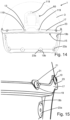
- Fig. 16 is an enlarged cross-section view similar to the cross-section view of Fig. 4 .
- the attachment screw 19 instead of being fastened with the threaded nut 19a, the attachment screw 19 is fastened with a counter screw 19b.
- the counter screw 19b has a threaded stem 19c that enters a threaded bore 19d of the attachment screw 19.
- the threaded stem 19 protrudes from a counter screw head 19e.
- the strip 9 is clamped against the helmet main body 3, thereby being securely attached.
- the strip 9 is clamped against the helmet main body 3 both by the head of the attachment screw 19 and by the counter screw head 19e.
- a wire attachment clip 50 is connected to the ballistic helmet 1 by means of the counter screw 19b.
- the wire attachment clip 50 is clamped against the inner face of the helmet main body 3, between the main body 3 and the counter screw head 19e.
- the wire attachment clip 50 has an attachment clip aperture 51, through which the threaded stem 19c of the counter screw 19b extends.
- the wire attachment clip 50 is thus arranged on the inner face of the main body 3, and is configured to removably secure a wire, such as a communication wire or a power supply to equipment attached to the ballistic helmet 1.
- Fig. 17 depicts an alternative helmet attachment arrangement 31.
- the strip-receiving pattern 37 is configured to receive one strip junction 11 that connects three strips 9.
- the strip-receiving pattern 37 exhibits three pattern ports 37a.
- Fig. 18 and Fig. 19 depict yet another alternative helmet attachment arrangement 31.
- This attachment arrangement 31 is configured to engage with a net 5 that is not a sheet net as shown and discussed above. Rather, the attachment arrangement 31 shown in Fig. 18 and Fig. 19 has a string-receiving pattern 37' that is configured to receive strings 9' of a net 5 that is made of strings, cords or the like, i.e. not a sheet material. Such strings 9' are shown in Fig. 19 , arranged in the string-receiving pattern 37' of the attachment arrangement 31.
- Fig. 14 depicts a ballistic helmet 1 shown without the net 5.
- Attached to the helmet main body 3 is a front attachment means 60, in the art commonly referred to as a shroud.
- the front attachment means 60 is used for attachment of helm-worn equipment that needs to be securely and removably attached to the helmet front portion.
- the front attachment means 60 is secured to the main body 3 by means of three screws 119.
- the screws 119 can be identical to the attachment screws 19 discussed above.
- the attachment means 60 is attached with one upper screw 119 and two lower screws 119. Furthermore, the two lower screws 119 are arranged in two respective recesses 23 of the edge band 17.
- the counter screws 19b are arranged snugly in the inner recesses 23a of the edge band 17. In this manner, the counter screws 19b will contribute in withstanding impact forces on the edge band 17, as a force on the edge band 17 may be transferred to the counter screws 19b. This is because the counter screws 19b (or the counter screw heads 19e in some embodiments) abuts the edge band 17 at the inner recesses 23.
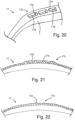
- FIG. 20 shows a portion of the edge band 17 at a wear-exposed portion 17c.
- the wear-exposed portion 17c comprises wear grooves 17d.
- the wear grooves 17d are separated by wear ribs 17e.
- Fig. 21 depicts the wear-exposed portion 17c with a cross-section side view. As appears from Fig. 21 , the thickness of the edge band 17 is thicker at the wear-exposed portion 17c, compared to the adjacent parts of the edge band.
- Fig. 22 shows the same wear-exposed portion 17c as shown in Fig. 21 , however after considerable wear.
- the wear ribs 17e are barely present since they have been worn down. This gives the user or owner an indication of the use of the helmet 1 onto which the edge band 17 is arranged.
Landscapes
- Engineering & Computer Science (AREA)
- General Engineering & Computer Science (AREA)
- Helmets And Other Head Coverings (AREA)
Description
- The present invention relates to a helmet and associated equipment, such as attachment systems for helmet-borne equipment.
- Helmets have been known for a long time and come in various designs and configurations. Some helmets are designed for withstanding impacts. Some helmets, typically used by military personnel, are designed also with anti-ballistic function. While it was previously common to produce ballistic helmets with a metal layer, it is now common to produce a helmet main body in a lighter composite material. Typically, the main body of anti-ballistic helmets is made of a cured fiber reinforced composite, which provides a ballistic protection while having alight weight.
- An example of an anti-ballistic helmet is given in publication
US20100229271 , where the main body comprises monolayers of unidirectional ultrahigh molecular weight polyethylene fibers. - While the main object of helmets is to protect from impacts and in some cases to provide anti-ballistic function, helmets are also used to carry various types of equipment. Such equipment may include lights, cameras, communication devices, camouflage devices and more.
- For attachment of such equipment, different systems are known. Some helmets comprise a net that spans across the external face of the helmet main body. Such a helmet is described in
GB 2474712 A independent claim 1. - Also known are patches that are glued to the external face of the helmet, which comprises one face of a hook-and-loop system, such as Velcro. Thus, to attach a device on the helmet, the device comprises a compatible face of the hook-and-loop system, so that the device can be easily attached and removed.
- The company Core Survival (www.coresurvival.com) presents an attachment patch for helmets, where the patch itself is attached to a net on the helmet, while the equipment itself is connected to the batch with a hook-and-loop system (Velcro). In addition to the hook-and-loop system, the patch comprises an attachment string that secures the equipment, such as a light-source, to the patch.
- Furthermore, in the front part of the helmet, it is known to attach a shroud. The shroud is provided with a connection interface, to which compatible equipment can be securely attached.
- An object of the present invention may be to provide a helmet attachment system that provides advantages compared to the known solutions in the art.
- Another object may be to provide a helmet attachment system that reduces the risk of unintentional removal (loss) of attached equipment.
- Furthermore, an object may be to provide a helmet attachment system that is less exposed to wear during use.
- Other possible objects will appear from the discussion below, where various advantageous features are presented.
- The objects mentioned above are solved by a helmet attachment system as disclosed in
independent claim 1. - According to a first aspect of the invention, there is provided a helmet attachment arrangement that has a base layer and an attachment layer. The attachment layer is attached on one face of the base layer. The attachment layer comprises a plurality of attachment layer sections that have a mutual distance and that together define a string-receiving pattern.
- As will become apparent from the description of the helmet attachment arrangement herein, the helmet attachment arrangement can be attached between the main body of a helmet and a net attached to the main body.
- According to an embodiment of the invention, the string-receiving pattern comprises at least three pattern ports, through which strings of a net can enter and exit the string-receiving pattern. In some embodiments the string-receiving pattern can have four pattern ports.
- Advantageously, the attachment layer can comprise a part of a hook-and-loop attachment system. Such a hook-and-loop system is typically known and referred to as Velcro. Other attachment systems can however also be used, for instance snap buttons (typically used with raincoats and the like).
- In some advantageous embodiments, the string-receiving pattern can be a strip-receiving pattern. It will then be configured to receive strips of a sheet net. The strips of a sheet net will exhibit a flat configuration with two opposite and parallel faces. Such a sheet net will be discussed in further detail below.
- The helmet attachment arrangement can comprise a flat portion configured to follow an external face of a helmet. Moreover, it can further comprise auxiliary attachment means that extend out from the flat portion.
- Typically, the auxiliary attachment means can be extensions of the attachment layer sections, which can be bent up / curve up from the shape of the flat portion and which can be folded around a piece of equipment. Advantageously, the auxiliary attachment means can also comprise a hook-and-loop system, a strap buckle, snap buttons, or other suitable attachment means that can attach two or more auxiliary attachment means together.
- According to a second aspect of the present invention, there is provided a helmet having a helmet main body. The main body has a helmet edge that defines an aperture for reception of a user's head. The helmet further has a net that extends over or along the external surface of the main body. The net comprises strings that completely encircles net apertures.
- In some embodiments, the net comprises less than 60, 40, or even less than 30 fully encircled net apertures. In some embodiments, the net comprises even less than 20 net apertures that are fully encircled by the net strings. Along the periphery of the net, there can advantageously be strings having free ends, which are attached to the helmet main body.
- In some embodiments of the helmet according to the invention, the main body can be made of an anti-ballistic material. Such an anti-ballistic material can advantageously comprise a fiber-reinforced composite. Such a composite can in preferred embodiments be cured or consolidated during production of the helmet main body.
- In some embodiments, the net can be a sheet net, which is made of a sheet material from which said net apertures are cut.
- With the term sheet net is meant a net having strings in the form of strips that have a flat configuration, meaning that they have a parallel and substantially flat upper and lower face. Moreover, the width of the strips will be larger than their height. Advantageously, the ratio between the width and the height of the strips can be at least 2:1, or even more preferably at least 4:1 or even 8:1.
- In some embodiments, the helmet edge can be provided with an edge band that has a plurality of recesses. Furthermore, the net can comprise a plurality of free strings, the ends of which are attached to the helmet main body.
- Preferably, the free strings can be attached to the helmet main body by means of attachment clamps.
- Furthermore, the attachment clamps can in some embodiments be at least partially arranged in the recesses of the edge band.
- In some embodiments of the helmet according to the invention, the attachment screws can extend through an attachment aperture that extends through the main body (i.e. through the wall of the main body). The attachment clamps, which fasten free strings of the net to the main body, can be attached by the attachment screws.
- The net can in some embodiments be a sheet net. In such embodiments the attachment apertures can comprise strip-receiving apertures that have a straight edge against which the free strips of the net abut.
- Advantageously, the edge band further has inner recesses that are arranged on the internal side of the main body. Preferably, the free strings or free strips of the net extend through the attachment apertures, and are clamped to the main body both by the attachment clamp and by an additional clamp, such as a counter screw head, on the opposite (i.e. inner) side of the main body.
- The said strip-receiving apertures can advantageously have a shape similar to the Greek capitol letter omega, i.e. like a circular aperture combined with a slit-shaped aperture at the periphery of the circular aperture.
- The helmet can in some embodiments have an edge band that comprises a wear indication means.
- The wear indication means can for instance comprise a wear indicator layer embedded in the edge band, behind a wear layer. In other embodiments, the wear indication means can include a wear groove.
- Advantageously, in embodiments where the wear indication means comprises a wear groove, there may be several wear grooves divided by wear ribs.
- In some embodiments, the helmet can have a front attachment means that is attached to the front part of the main body by means of at least three screws. One screw can be an upper screw and two screws can be lower screws. According to such an embodiment, the two lower screws can be arranged at least partly in a recess of an edge band arranged to the helmet edge.
- In this way, since the two lower screws for connection of the front attachment means (typically referred to as a shroud) can be the same as two of the attachment screws used to attach the net, one only needs one additional screw to attach it with three screws.
- In some embodiments of the helmet, the net can be attached to the main body by means of attachment screws, and one or more wire attachment clips can be connected to the internal face of the main body by means of threaded nuts, by means of the heads of counter screws, or by means of discs.
- In embodiments where a disc is used to attach the wire attachment clip, the disc can typically be retained in place by means of a nut or counter screw that engages with the attachment screw.
- According to a third aspect of the present invention, there is provided a helmet attachment system that comprises a helmet, a net arranged on the helmet, and a helmet attachment arrangement as presented above and in one or more of the appending claims.
- While several advantageous and possible features of the invention have been presented above, some non-limiting and more detailed examples of embodiment will be presented in the following with reference to the drawings, in which
- Fig. 1a to Fig. 1d
- show perspective views of various embodiments a ballistic helmet;
- Fig. 2
- is an enlarged view of an edge-portion of a helmet;
- Fig. 3
- is another enlarged view of an edge-portion of a helmet;
- Fig. 4
- is a principle, enlarged cross section view of an edge-portion;
- Fig. 5
- is another principle, enlarged cross section view of an edge portion;
- Fig. 6
- is a perspective view of an attachment arrangement according to the invention;
- Fig. 7
- is a top view of the attachment arrangement shown in
Fig. 6 ; - Fig. 8
- is a perspective view of the attachment arrangement shown in
Fig. 6 , when attached to a ballistic helmet; - Fig. 9
- is a perspective view of another embodiment of an attachment arrangement;
- Fig. 10
- shows the attachment arrangement according to
Fig. 9 attached to a ballistic helmet; - Fig. 11
- is a perspective view showing a helmet-worn equipment secured with the attachment arrangement shown in
Fig. 9 and Fig. 10 ; - Fig. 12
- is a perspective view showing another embodiment of an attachment arrangement, when secured to a ballistic helmet;
- Fig. 13
- shows a helmet-worn equipment secured to a ballistic helmet with the attachment arrangement shown in
Fig. 12 ; - Fig. 14
- is a front view of a ballistic helmet having a front attachment means;
- Fig. 15
- is an enlarged portion of
Fig. 14 ; - Fig. 16
- an enlarged cross section view showing an attachment section;
- Fig. 17
- is a schematic top view of another embodiment of an attachment arrangement;
- Fig. 18
- is a schematic top view of yet another embodiment of an attachment arrangement;
- Fig. 19
- is a schematic top view showing the attachment arrangement of
Fig. 18 in an attached state; - Fig. 20
- shows a principle perspective view of a portion of an edge band having a wear indication means;
- Fig. 21
- is a principle cross section view through the edge band shown in
Fig. 20 ; and - Fig. 22
- is a principle cross section view through the edge band shown in
Fig. 20 , after considerable wear. -
Fig. 1a to Fig. 1d depictvarious helmets 1. In these example embodiments, thehelmet 1 is a ballistic helmet. The skilled person will however appreciate that the discussed features also can be used on other types of helmets. - Referring to
Fig. 1a , thehelmet 1 has amain body 3 that is made of an anti-ballistic material. Advantageously, themain body 3 can be made of a consolidated / cured fiber-reinforced composite material. - Onto the
main body 3 there is arranged anet 5. In the shown embodiment, the net is in the form of asheet net 5, as the net is made of a sheet material. Other embodiments may involve another type of net, such as a net made of strings, strands or cords. - Advantageously, the
sheet net 5 can be made of a sheet material from whichapertures 7 are cut, such as by laser cutting, punching or other methods. - The
sheet net 5 comprises saidnet apertures 7, which are at least partially defined bystrips 9. Some of thenet apertures 7 are completely defined (encircled) by thestrips 9. Thestrips 9 extend betweenstrip junctions 11. Somestrips 9 extend between astrip junction 11 and anattachment section 13. - In the embodiment shown in
Fig. 1a , all thestrip junctions 11 comprises threestrips 9 extending out from thestrip junctions 11. In the embodiment shown inFig. 1c , somestrip junctions 11 have four strips, while other junctions have three. In further embodiments,strip junctions 11 can have even more strips 9. - As any common helmet, the helmet
main body 3 comprises a helmet opening configured for receiving the head of a user. The helmet opening is defined by ahelmet edge 15. Attached to thehelmet edge 15, there is anedge band 17, which in the shown embodiments is a continuous list that extends along theentire helmet edge 15. As shown withFig. 1a to Fig. 1d , thesheet net 5 is attached to themain body 3 of thehelmet 1 along the extension of theedge band 17. At theattachment sections 13, the free ends of theperipheral strips 9 are attached. In this embodiment, the free ends of theperipheral strips 9 are attached with a screw and clamp arrangement. -
Fig. 2 depict an enlarged portion of thehelmet 1 along a portion of thehelmet edge 15. The head of anattachment screw 19 and anattachment clamp 21 is shown. - Also shown in
Fig. 2 , theedge band 17 comprises a plurality ofrecesses 23 that receives the attachment clamps 21. Therecesses 23 contributes in preventing theattachment sections 13 from getting entangled. Therecesses 23 also provide some protection for theattachment sections 13, such as from impacts that may affect the attachment function. - By fastening the
sheet net 5 immediately adjacent theedge band 17, thesheet net 5 covers substantially the entire external face of the main body 3 (except for the exposed areas in the net apertures of course). Furthermore, one avoids extending thesheet net 5 around thehelmet edge 15, where thesheet net 5 would be exposed to substantial wear. -
Fig. 3 shows another enlarged portion of the helmetmain body 3 along a portion of thehelmet edge 15. For illustrational purpose, astrip 9, theattachment screw 19 and theattachment clamp 21 have been removed, making anattachment aperture 25 visible. - The function of the
attachment screw 19 and theattachment clamp 21 is shown inFig. 4. Fig. 4 is an enlarged principle cross section through a portion of themain body 3 along thehelmet edge 15, and through anattachment aperture 25. As shown, theattachment screw 19 extends through theattachment aperture 25 and is fastened with a threadednut 19a in a conventional manner. As will be shown further below, other attachment solutions are also possible. - The
strip 9 is clamped between theattachment clamp 21 and the helmetmain body 3, when theattachment screw 19 is tightened with theattachment nut 19a. - As shown in
Fig. 3 , theattachment aperture 25 comprises a strip-receivingsection 25a and a screw-receivingsection 25b. As shown, the strip-receivingsection 25a and the screw-receivingsection 25b together form one single aperture. In other embodiments, however, it is possible to form the strip-receivingsection 25a and the screw-receivingsection 25b are two distinct, adjacent apertures. Advantageously, the strip-receivingsection 25a comprises a substantially straight edge, against which thestrip 9 abuts when in a fastened stated. - Referring again to
Fig. 4 , the cross-section of theedge band 17 has a generally U-shaped form. The U-form constitutes a channel in which the edge of themain body 3 is received. - The U-shape thus has two parallel walls. The
recesses 23 discussed above are in one of these parallel walls. -
Fig. 5 depicts another cross-section through an edge portion of themain body 3, showing again how the edge of themain body 3 is received in theedge band 17. In addition,Fig. 5 shows a wear indication means in the form of awear indicator layer 17a that is a part of theedge band 17. Thewear indicator layer 17a has another colour than the rest of theedge band 17. Awear layer 17b is arranged on the external side of theedge band 17, with respect to thewear indicator layer 17a. Advantageously, thewear layer 17a is of the same material as the other parts of theedge band 17, except for thewear indicator layer 17a. When thewear layer 17b is worn away, after use of theballistic helmet 1, thewear indicator layer 17a becomes visible. Thus, the user will be able to tell that theballistic helmet 1 has been used for some time. - It will be understood by the person of skill, that the
wear indicator layer 17a and thewear layer 17b may be of the same material, however having a different colour to enable the wear indicating function. - Another embodiment of a wear indication means will be discussed further below with reference to
Fig. 20 to Fig. 22 . - In
Fig. 1a and Fig. 1b , there is indicated two wear-exposedportions 17c of theedge band 17, where thewear indicator layer 17a may be integrated in theedge band 17. - A particular advantage with the
wear indicator layer 17a, is that by enabling indication of wear of theballistic helmet 1, one can avoid that the edge of themain body 3 is exposed to water or other contaminants. Such contaminants could in some embodiments enter into the anti-ballistic material of themain body 3, and thus possibly reduce its anti-ballistic function. - The
edge band 17 can be attached to the helmetmain body 3 by any suitable means, for instance with an adhesive. - In the following, some example embodiments of a novel helmet attachment system will be presented.
-
Fig. 6 depicts ahelmet attachment arrangement 31 with a perspective view. Thehelmet attachment arrangement 31 has the form of a patch. Theattachment arrangement 31 has abase layer 33. Thebase layer 33 can advantageously be made of a fabric, which makes theattachment arrangement 31 flexible. Attached to thebase layer 33 there is anattachment layer 35. As shown inFig. 6 , due to the thickness of theattachment layer 35, the upper face of theattachment layer 35 is elevated with respect to the upper face of thebase layer 33. - In the embodiment shown in
Fig. 6 , there are fourattachment layer sections 35a. Theattachment layer sections 35a are arranged on thebase layer 33 with a mutual distance to each other, thereby forming a pattern. The pattern between theattachment layer sections 35a is a string-receivingpattern 37. The string-receivingpattern 37 is configured to receive strings orstrips 9 of the sheet net 5 (cf.Fig. 1a ) when theattachment arrangement 31 is interposed between the helmetmain body 3 and thesheet net 5. This is shown with the perspective view ofFig. 8 . As the string-receivingpattern 37 in this embodiment is configured to receivestrips 9 of the net 5, which is asheet net 5, it may be termed a strip-receivingpattern 37. -
Fig. 7 is a top view of thehelmet attachment arrangement 31. In this embodiment, the strip-receivingpattern 37 is configured to receive twostrip junctions 11 that each connects threestrips 9. The twostrip junctions 11 are interconnected with acommon strip 9. Four strips exit the strip-receivingpattern 37 through fourpattern ports 37a. -
Fig. 8 shows thehelmet attachment arrangement 31 when placed between the helmetmain body 3 and thesheet net 5, with the strip-receivingpattern 37 aligned with thesheet net 5. The engagement between the edges of theattachment layer sections 35a, which define the strip-receivingpattern 37, and thesheet net 5, will secure theattachment arrangement 31 to theballistic helmet 1. - Advantageously, the upper face of the
attachment layer 35 can comprise one part of a hook-and-loop system, such as the system often referred to as Velcro. In such embodiments, equipment that shall be attached to theballistic helmet 1 can be fastened simply by placing the equipment onto theattachment arrangement 31 on the helmet (provided of course that the equipment is provided with a mating part of the hook-and-loop system). - In other embodiments, instead of or in addition to the hook-and-loop system, the
attachment layer 35 can comprise other attachment means, for instance snap-buttons / snap fasteners. - In the embodiment discussed with reference to and shown in
Fig. 6 ,Fig. 7 and Fig. 8 , theentire attachment arrangement 31 had a substantially flat configuration when mounted to theballistic helmet 1. Hence, the shownattachment arrangement 31 constitutes aflat portion 31a. - The
attachment arrangement 31 depicted inFig. 9 , however, has aflat portion 31a and is further provided with auxiliary attachment means 39 that extend out from theflat portion 31a. In the embodiment shown inFig. 9 , theflat portion 31a corresponds to theattachment arrangement 31 shown inFig. 6 to Fig. 8 . - In the embodiment shown in
Fig. 9 , the auxiliary attachment means 39 are in the form of flexible attachment flaps. As appears fromFig. 9 and fromFig. 10 , the auxiliary attachment means 39 are configured as extensions of theattachment layer sections 35a beyond theflat portion 31a. - The auxiliary attachment means 39 can be bent upwards from the surface of the helmet
main body 3, to envelop a piece of equipment. This is shown inFig. 11 , whereequipment 101 in the form of a portable light is attached to thehelmet attachment arrangement 31. As will be understood, before attaching theportable equipment 101, theattachment arrangement 31 was attached to theballistic helmet 1. - In the embodiment shown in
Fig. 9 to Fig. 11 , the auxiliary attachment means 39 are also provided with a hook-and-loop system. Thus, opposite auxiliary attachment means 39, such as attachment flaps 39 provided on opposite sides of theflat portion 31a, can connect to each other when being folded over theportable equipment 101. Other solutions for connecting the auxiliary attachment means together can also be used, for instance a strap buckle or a strap snap-on clip. - The
helmet attachment arrangement 31 having the auxiliary attachment means 39, may be provided with anequipment aperture 39a in the auxiliary attachment means 39. Theequipment aperture 39a permits communication between the attachedequipment 101 and the ambience. For instance, if the equipment is in form of a camera, the camera can capture images through the opening provided by theequipment aperture 39a. Similarly, if theequipment 101 is a lighting device, light can be emitted through theequipment aperture 39a. -
Fig. 12 and Fig. 13 shows another embodiment of ahelmet attachment arrangement 31 that has auxiliary attachment means 39. In this embodiment, two of the fourattachment layer sections 35a are extended with auxiliary attachment means 39, while the other twoattachment layer sections 35 are arranged within theflat portion 31a. -
Fig. 14 depicts thehelmet 1 with a front view, however without thesheet net 5.Fig. 15 shows an enlarged portion ofFig. 14 . - In advantageous embodiments, such as shown in
Fig. 14 , theedge band 17 is an endless list extending along theentire helmet edge 15 of themain body 3. Notably, theedge band 17 is not attached to the helmetmain body 3 by means of the attachment screws 19. Rather, the attachment screws 19 are used to attach thesheet net 5. - In the embodiment shown in
Fig. 14 and Fig. 15 , the attachment screws 19 are fastened by means of acounter screw 19b. The function of thecounter screw 19b will be discussed below, with reference toFig. 16 .Fig. 15 shows particularly well how therecesses 23 of theedge band 17 protects theattachment clamp 21, as it is at least to some degree recessed in therecess 23. Also shown infig. 14 and Fig. 15 , theedge band 17 is further provided withinner recesses 23a arranged on the inside face of the helmetmain body 3. As appears fromFig. 15 , the counter screws 19b are recessed in theinner recesses 23a, and are thus also protected from impacts and entanglement. -
Fig. 16 is an enlarged cross-section view similar to the cross-section view ofFig. 4 . As appears fromFig. 16 , instead of being fastened with the threadednut 19a, theattachment screw 19 is fastened with acounter screw 19b. Thecounter screw 19b has a threadedstem 19c that enters a threadedbore 19d of theattachment screw 19. The threadedstem 19 protrudes from acounter screw head 19e. As with the embodiment shown inFig. 4 , thestrip 9 is clamped against the helmetmain body 3, thereby being securely attached. Thestrip 9 is clamped against the helmetmain body 3 both by the head of theattachment screw 19 and by thecounter screw head 19e. - Still referring to
Fig. 16 , awire attachment clip 50 is connected to theballistic helmet 1 by means of thecounter screw 19b. In particular, thewire attachment clip 50 is clamped against the inner face of the helmetmain body 3, between themain body 3 and thecounter screw head 19e. Thewire attachment clip 50 has anattachment clip aperture 51, through which the threadedstem 19c of thecounter screw 19b extends. - The
wire attachment clip 50 is thus arranged on the inner face of themain body 3, and is configured to removably secure a wire, such as a communication wire or a power supply to equipment attached to theballistic helmet 1. - It will be appreciated that along the
helmet edge 15, there areadditional attachment sections 13 corresponding to the one shown inFig. 16 , however without thewire attachment clip 50. -
Fig. 17 depicts an alternativehelmet attachment arrangement 31. In this embodiment, the strip-receivingpattern 37 is configured to receive onestrip junction 11 that connects threestrips 9. Thus, the strip-receivingpattern 37 exhibits threepattern ports 37a. -
Fig. 18 and Fig. 19 depict yet another alternativehelmet attachment arrangement 31. Thisattachment arrangement 31 is configured to engage with a net 5 that is not a sheet net as shown and discussed above. Rather, theattachment arrangement 31 shown inFig. 18 and Fig. 19 has a string-receiving pattern 37' that is configured to receive strings 9' of a net 5 that is made of strings, cords or the like, i.e. not a sheet material. Such strings 9' are shown inFig. 19 , arranged in the string-receiving pattern 37' of theattachment arrangement 31. - It is again referred to
Fig. 14 , which depicts aballistic helmet 1 shown without thenet 5. Attached to the helmetmain body 3 is a front attachment means 60, in the art commonly referred to as a shroud. The front attachment means 60 is used for attachment of helm-worn equipment that needs to be securely and removably attached to the helmet front portion. The front attachment means 60 is secured to themain body 3 by means of threescrews 119. Advantageously, thescrews 119 can be identical to the attachment screws 19 discussed above. - The attachment means 60 is attached with one
upper screw 119 and twolower screws 119. Furthermore, the twolower screws 119 are arranged in tworespective recesses 23 of theedge band 17. - Also shown in
Fig. 14 , the counter screws 19b, or the counter screw heads 19e in some embodiments, are arranged snugly in theinner recesses 23a of theedge band 17. In this manner, the counter screws 19b will contribute in withstanding impact forces on theedge band 17, as a force on theedge band 17 may be transferred to the counter screws 19b. This is because the counter screws 19b (or the counter screw heads 19e in some embodiments) abuts theedge band 17 at theinner recesses 23. - Reference is now made to
Fig. 20, Fig. 21 and Fig. 22 , which show another embodiment of a wear indication means 17a.Fig. 20 shows a portion of theedge band 17 at a wear-exposedportion 17c. The wear-exposedportion 17c compriseswear grooves 17d. Thewear grooves 17d are separated bywear ribs 17e. -
Fig. 21 depicts the wear-exposedportion 17c with a cross-section side view. As appears fromFig. 21 , the thickness of theedge band 17 is thicker at the wear-exposedportion 17c, compared to the adjacent parts of the edge band. -
Fig. 22 shows the same wear-exposedportion 17c as shown inFig. 21 , however after considerable wear. Thewear ribs 17e are barely present since they have been worn down. This gives the user or owner an indication of the use of thehelmet 1 onto which theedge band 17 is arranged.
Claims (15)
- A helmet attachment system (5, 31) comprising a helmet (1), a net (5) arranged on the helmet (1), and a helmet attachment arrangement (31), characterized in that the helmet attachment arrangement (31) comprises a base layer (33) and an attachment layer (35), wherein the attachment layer (35) is attached on one face of the base layer (33), and wherein the attachment layer (35) comprises a plurality of attachment layer sections (35a) that have a mutual distance and that together define a string-receiving pattern (37) configured to receive strings (9) of said net (5).
- A helmet attachment system (5, 31) according to claim 1, characterized in that the helmet attachment arrangement (31) further comprises attachment means.
- A helmet attachment system (5, 31) according to claim 1 or claim 2, characterized in that the string-receiving pattern (37) comprises at least three pattern ports (37a), through which strings (11) of a net (5) can enter and exit the string-receiving pattern (37).
- A helmet attachment system (5, 31) according to claim 1, claim 2, or claim 3, characterized in that the attachment layer (35) comprises a part of a hook-and-loop attachment system.
- A helmet attachment system (5, 31) according to one of the preceding claims, characterized in that the string-receiving pattern (37) is a strip-receiving pattern (37), as it is configured to receive strips (9) of a sheet net (5).
- A helmet attachment system (5, 31) according to one of the preceding claims, characterized in that the helmet attachment arrangement (31) comprises a flat portion (31a) configured to follow an external face of the helmet (1), and that the helmet attachment arrangement (31) further comprises auxiliary attachment means (39) that extend out from the flat portion (31a).
- A helmet attachment system (5, 31) according to one of the preceding claims, characterized in that the helmet (1) comprises a helmet main body (3) having a helmet edge (15) defining an aperture for receiving a user's head, and in that the net (5) extends over the external surface of the main body (3), wherein the net (5) comprises strings (9) that completely encircles net apertures (7).
- A helmet attachment system (5, 31) according to claim 7, characterized in that the net (5) is a sheet net (5), which is made of a sheet material from which said net apertures (7) are cut.
- A helmet attachment system (5, 31) according to claim 7 or claim 8, characterized in that- the helmet edge (15) is provided with an edge band (17) comprising a plurality of recesses (23);- the net (5) comprises a plurality of free strings (9), which are attached to the helmet main body (3) with attachment clamps (21); and that- the attachment clamps (21) are at least partially arranged in the recesses (23) of the edge band (17).
- A helmet attachment system (5, 31) according to one of claims 7, 8 or 9, characterized in that it further comprises- attachment screws (19) extending through an attachment aperture (25) that extends through the main body (3), wherein attachment clamps (21) that fasten free strings (9) of the net (5) are attached by the attachment screws (19).
- A helmet attachment system (5, 31) according to claim 10, characterized in that the net (5) is a sheet net and that the attachment apertures (25) comprise strip-receiving apertures (25a) having a straight edge against which the free strips (9) of the net abut.
- A helmet attachment system (5, 31) according to one of the claims 7 to 11, characterized in that it comprises an edge band (17) and in that the edge band (17) comprises a wear indication means (17a).
- A helmet attachment system (5, 31) according to claim 12, characterized in that the wear indication means (17a) comprises- a wear indicator layer embedded in the edge band (17), behind a wear layer (17b); or- a wear groove (17d).
- A helmet attachment system (5, 31) according to one of claims 7 to 13, characterized in that it comprises a front attachment means (60) that is attached to the front part of the main body (3) by means of at least three screws (119), of which one screw is an upper screw and two screws are lower screws, wherein the two lower screws are arranged at least partly in a recess (23) of an edge band (17) arranged to the helmet edge (15).
- A helmet attachment system (5, 31) according to one of claims 7 to 14, characterized in that the net (5) is attached to the main body (3) by means of attachment screws (19) and in that a wire attachment clip (50) is connected to the internal face of the main body (3) by means of a threaded nut (19a), by means of the head (19e) of a counter screw (19b), or by means of a disc.
Priority Applications (1)
| Application Number | Priority Date | Filing Date | Title |
|---|---|---|---|
| EP23192431.7A EP4269933A3 (en) | 2019-11-18 | 2020-11-10 | Helmet and associated equipment |
Applications Claiming Priority (2)
| Application Number | Priority Date | Filing Date | Title |
|---|---|---|---|
| NO20191369A NO345894B1 (en) | 2019-11-18 | 2019-11-18 | Helmet attachment system and associated equipment |
| PCT/EP2020/081625 WO2021099183A1 (en) | 2019-11-18 | 2020-11-10 | Helmet and associated equipment |
Related Child Applications (2)
| Application Number | Title | Priority Date | Filing Date |
|---|---|---|---|
| EP23192431.7A Division EP4269933A3 (en) | 2019-11-18 | 2020-11-10 | Helmet and associated equipment |
| EP23192431.7A Division-Into EP4269933A3 (en) | 2019-11-18 | 2020-11-10 | Helmet and associated equipment |
Publications (3)
| Publication Number | Publication Date |
|---|---|
| EP4061171A1 EP4061171A1 (en) | 2022-09-28 |
| EP4061171C0 EP4061171C0 (en) | 2023-11-01 |
| EP4061171B1 true EP4061171B1 (en) | 2023-11-01 |
Family
ID=73288632
Family Applications (2)
| Application Number | Title | Priority Date | Filing Date |
|---|---|---|---|
| EP20804266.3A Active EP4061171B1 (en) | 2019-11-18 | 2020-11-10 | Helmet and associated equipment |
| EP23192431.7A Pending EP4269933A3 (en) | 2019-11-18 | 2020-11-10 | Helmet and associated equipment |
Family Applications After (1)
| Application Number | Title | Priority Date | Filing Date |
|---|---|---|---|
| EP23192431.7A Pending EP4269933A3 (en) | 2019-11-18 | 2020-11-10 | Helmet and associated equipment |
Country Status (6)
| Country | Link |
|---|---|
| US (1) | US20220378139A1 (en) |
| EP (2) | EP4061171B1 (en) |
| CA (1) | CA3159354A1 (en) |
| NO (1) | NO345894B1 (en) |
| PL (1) | PL4061171T3 (en) |
| WO (1) | WO2021099183A1 (en) |
Families Citing this family (1)
| Publication number | Priority date | Publication date | Assignee | Title |
|---|---|---|---|---|
| USD994991S1 (en) * | 2019-11-13 | 2023-08-08 | Nfm As | Fixing device for helmets |
Family Cites Families (20)
| Publication number | Priority date | Publication date | Assignee | Title |
|---|---|---|---|---|
| US3153792A (en) * | 1963-07-09 | 1964-10-27 | Michael T Marietta | Two part detachable liner for safety helmets |
| US3872511A (en) * | 1974-03-11 | 1975-03-25 | Larcher Angelo C | Protective headgear |
| DE3112924A1 (en) * | 1981-03-31 | 1982-10-07 | Ogus Netze und Wirkwaren GmbH & Co KG, 4050 Mönchengladbach | Camouflage net for helmets |
| US5481762A (en) * | 1989-01-25 | 1996-01-09 | Giro Sport Design, Inc. | Helmet having a planar-molded infrastructure |
| US7143452B1 (en) * | 2004-08-02 | 2006-12-05 | Rossini Michael J | Multipurpose helmet camouflage system |
| US7353770B2 (en) * | 2005-12-06 | 2008-04-08 | Sanguinetti Cheri | Visual wear indicator for footwear |
| FR2895646B1 (en) * | 2006-01-04 | 2008-02-08 | Joseph Mazoyer | HELMET CLOTHING ENCLOSURE, IN PARTICULAR FOR A HELMET USED FOR SKIING PRACTICE, AND HELMET PROVIDED WITH THIS CLOTHING ENVELOPE |
| US20100229271A1 (en) | 2007-10-12 | 2010-09-16 | Marissen Roelof R | Helmet containing polyethylene fibers |
| IT1393926B1 (en) * | 2008-07-24 | 2012-05-17 | New Max Srl | STRUCTURE OF REINFORCED PROTECTION HELMET. |
| GB2474712A (en) * | 2009-10-26 | 2011-04-27 | Thomas Jacks Ltd | Helmet cover |
| KR20120043636A (en) * | 2010-10-26 | 2012-05-04 | 가부시키가이샤 한도오따이 에네루기 켄큐쇼 | Plasma treatment apparatus and plasma cvd apparatus |
| US11766085B2 (en) * | 2011-02-09 | 2023-09-26 | 6D Helmets, Llc | Omnidirectional energy management systems and methods |
| US10178889B2 (en) * | 2011-08-01 | 2019-01-15 | Brian Wacter | Customizable head protection |
| US20130174323A1 (en) * | 2012-01-11 | 2013-07-11 | Daniel McFall | Illuminated Headgear Cover |
| US20170065018A1 (en) * | 2012-06-15 | 2017-03-09 | Vyatek Sports, Inc. | Sports helmet with collapsible modular elements |
| US20180192726A1 (en) * | 2017-01-10 | 2018-07-12 | Hmount Ltd | Plastic helmet mounting assembly |
| CA3008514A1 (en) * | 2017-06-16 | 2018-12-16 | Sekund Skull Inc. | Protective device for use with helmets |
| US10433610B2 (en) * | 2017-11-16 | 2019-10-08 | Choon Kee Lee | Mechanical-waves attenuating protective headgear |
| CN110017733A (en) * | 2019-05-10 | 2019-07-16 | 安瑞装甲材料(芜湖)科技有限公司 | A kind of bulletproof halmet |
| US11229254B1 (en) * | 2020-03-31 | 2022-01-25 | Rose Elizabeth Matteucci | Dispersing helmet safety system and method |
-
2019
- 2019-11-18 NO NO20191369A patent/NO345894B1/en unknown
-
2020
- 2020-11-10 US US17/775,128 patent/US20220378139A1/en active Pending
- 2020-11-10 CA CA3159354A patent/CA3159354A1/en active Pending
- 2020-11-10 WO PCT/EP2020/081625 patent/WO2021099183A1/en unknown
- 2020-11-10 EP EP20804266.3A patent/EP4061171B1/en active Active
- 2020-11-10 EP EP23192431.7A patent/EP4269933A3/en active Pending
- 2020-11-10 PL PL20804266.3T patent/PL4061171T3/en unknown
Also Published As
| Publication number | Publication date |
|---|---|
| EP4061171C0 (en) | 2023-11-01 |
| PL4061171T3 (en) | 2024-05-06 |
| NO345894B1 (en) | 2021-10-04 |
| EP4269933A2 (en) | 2023-11-01 |
| CA3159354A1 (en) | 2021-05-27 |
| WO2021099183A1 (en) | 2021-05-27 |
| EP4269933A3 (en) | 2024-01-24 |
| NO20191369A1 (en) | 2021-05-19 |
| EP4061171A1 (en) | 2022-09-28 |
| US20220378139A1 (en) | 2022-12-01 |
Similar Documents
| Publication | Publication Date | Title |
|---|---|---|
| US11659881B2 (en) | Helmet cover assembly having at least one mounting device | |
| AU2020270492B2 (en) | Helmet mounted visor | |
| US5638544A (en) | Military helmet with camouflage band retaining system and method for retaining a camouflage band on a military helmet | |
| US20170299340A1 (en) | Versatile Protective Helmet Applique Assembly | |
| EP3595472B1 (en) | Mounting rail assembly | |
| US9113673B2 (en) | Visor assembly for a helmet | |
| EP4061171B1 (en) | Helmet and associated equipment | |
| WO2015030703A1 (en) | Versatile protective helmet applique assembly | |
| US20160128413A1 (en) | Protective headgear | |
| US11229252B2 (en) | Helmet mounted shroud | |
| AU2016216559B2 (en) | Ballistic vest system with ballistic ridge component | |
| WO2024155531A1 (en) | Helmet rail with line management | |
| CA3164290A1 (en) | Anti-ballistic plate assembly | |
| JP3401113B2 (en) | Rider protector |
Legal Events
| Date | Code | Title | Description |
|---|---|---|---|
| STAA | Information on the status of an ep patent application or granted ep patent |
Free format text: STATUS: UNKNOWN |
|
| STAA | Information on the status of an ep patent application or granted ep patent |
Free format text: STATUS: THE INTERNATIONAL PUBLICATION HAS BEEN MADE |
|
| PUAI | Public reference made under article 153(3) epc to a published international application that has entered the european phase |
Free format text: ORIGINAL CODE: 0009012 |
|
| STAA | Information on the status of an ep patent application or granted ep patent |
Free format text: STATUS: REQUEST FOR EXAMINATION WAS MADE |
|
| 17P | Request for examination filed |
Effective date: 20220614 |
|
| AK | Designated contracting states |
Kind code of ref document: A1 Designated state(s): AL AT BE BG CH CY CZ DE DK EE ES FI FR GB GR HR HU IE IS IT LI LT LU LV MC MK MT NL NO PL PT RO RS SE SI SK SM TR |
|
| DAV | Request for validation of the european patent (deleted) | ||
| DAX | Request for extension of the european patent (deleted) | ||
| GRAP | Despatch of communication of intention to grant a patent |
Free format text: ORIGINAL CODE: EPIDOSNIGR1 |
|
| STAA | Information on the status of an ep patent application or granted ep patent |
Free format text: STATUS: GRANT OF PATENT IS INTENDED |
|
| INTG | Intention to grant announced |
Effective date: 20230601 |
|
| RIN1 | Information on inventor provided before grant (corrected) |
Inventor name: LACH, MICHAL Inventor name: HVESSER, THOMAS |
|
| GRAS | Grant fee paid |
Free format text: ORIGINAL CODE: EPIDOSNIGR3 |
|
| GRAA | (expected) grant |
Free format text: ORIGINAL CODE: 0009210 |
|
| STAA | Information on the status of an ep patent application or granted ep patent |
Free format text: STATUS: THE PATENT HAS BEEN GRANTED |
|
| AK | Designated contracting states |
Kind code of ref document: B1 Designated state(s): AL AT BE BG CH CY CZ DE DK EE ES FI FR GB GR HR HU IE IS IT LI LT LU LV MC MK MT NL NO PL PT RO RS SE SI SK SM TR |
|
| REG | Reference to a national code |
Ref country code: GB Ref legal event code: FG4D |
|
| REG | Reference to a national code |
Ref country code: CH Ref legal event code: EP |
|
| REG | Reference to a national code |
Ref country code: IE Ref legal event code: FG4D |
|
| REG | Reference to a national code |
Ref country code: DE Ref legal event code: R096 Ref document number: 602020020410 Country of ref document: DE |
|
| U01 | Request for unitary effect filed |
Effective date: 20231121 |
|
| U07 | Unitary effect registered |
Designated state(s): AT BE BG DE DK EE FI FR IT LT LU LV MT NL PT SE SI Effective date: 20231128 |
|
| PG25 | Lapsed in a contracting state [announced via postgrant information from national office to epo] |
Ref country code: GR Free format text: LAPSE BECAUSE OF FAILURE TO SUBMIT A TRANSLATION OF THE DESCRIPTION OR TO PAY THE FEE WITHIN THE PRESCRIBED TIME-LIMIT Effective date: 20240202 |
|
| PG25 | Lapsed in a contracting state [announced via postgrant information from national office to epo] |
Ref country code: IS Free format text: LAPSE BECAUSE OF FAILURE TO SUBMIT A TRANSLATION OF THE DESCRIPTION OR TO PAY THE FEE WITHIN THE PRESCRIBED TIME-LIMIT Effective date: 20240301 |
|
| PG25 | Lapsed in a contracting state [announced via postgrant information from national office to epo] |
Ref country code: ES Free format text: LAPSE BECAUSE OF FAILURE TO SUBMIT A TRANSLATION OF THE DESCRIPTION OR TO PAY THE FEE WITHIN THE PRESCRIBED TIME-LIMIT Effective date: 20231101 |
|
| PG25 | Lapsed in a contracting state [announced via postgrant information from national office to epo] |
Ref country code: IS Free format text: LAPSE BECAUSE OF FAILURE TO SUBMIT A TRANSLATION OF THE DESCRIPTION OR TO PAY THE FEE WITHIN THE PRESCRIBED TIME-LIMIT Effective date: 20240301 Ref country code: GR Free format text: LAPSE BECAUSE OF FAILURE TO SUBMIT A TRANSLATION OF THE DESCRIPTION OR TO PAY THE FEE WITHIN THE PRESCRIBED TIME-LIMIT Effective date: 20240202 Ref country code: ES Free format text: LAPSE BECAUSE OF FAILURE TO SUBMIT A TRANSLATION OF THE DESCRIPTION OR TO PAY THE FEE WITHIN THE PRESCRIBED TIME-LIMIT Effective date: 20231101 |
|
| PGFP | Annual fee paid to national office [announced via postgrant information from national office to epo] |
Ref country code: CZ Payment date: 20240208 Year of fee payment: 4 |
|
| U21 | Renewal fee paid with penalty [unitary effect] |
Year of fee payment: 4 Effective date: 20240322 |
|
| PG25 | Lapsed in a contracting state [announced via postgrant information from national office to epo] |
Ref country code: RS Free format text: LAPSE BECAUSE OF FAILURE TO SUBMIT A TRANSLATION OF THE DESCRIPTION OR TO PAY THE FEE WITHIN THE PRESCRIBED TIME-LIMIT Effective date: 20231101 Ref country code: NO Free format text: LAPSE BECAUSE OF FAILURE TO SUBMIT A TRANSLATION OF THE DESCRIPTION OR TO PAY THE FEE WITHIN THE PRESCRIBED TIME-LIMIT Effective date: 20240201 Ref country code: HR Free format text: LAPSE BECAUSE OF FAILURE TO SUBMIT A TRANSLATION OF THE DESCRIPTION OR TO PAY THE FEE WITHIN THE PRESCRIBED TIME-LIMIT Effective date: 20231101 |
|
| PGFP | Annual fee paid to national office [announced via postgrant information from national office to epo] |
Ref country code: TR Payment date: 20240131 Year of fee payment: 4 |
|
| REG | Reference to a national code |
Ref country code: CH Ref legal event code: PL |
|
| PG25 | Lapsed in a contracting state [announced via postgrant information from national office to epo] |
Ref country code: CH Free format text: LAPSE BECAUSE OF NON-PAYMENT OF DUE FEES Effective date: 20231130 |
|
| PG25 | Lapsed in a contracting state [announced via postgrant information from national office to epo] |
Ref country code: SK Free format text: LAPSE BECAUSE OF FAILURE TO SUBMIT A TRANSLATION OF THE DESCRIPTION OR TO PAY THE FEE WITHIN THE PRESCRIBED TIME-LIMIT Effective date: 20231101 |
|
| PG25 | Lapsed in a contracting state [announced via postgrant information from national office to epo] |
Ref country code: SM Free format text: LAPSE BECAUSE OF FAILURE TO SUBMIT A TRANSLATION OF THE DESCRIPTION OR TO PAY THE FEE WITHIN THE PRESCRIBED TIME-LIMIT Effective date: 20231101 Ref country code: SK Free format text: LAPSE BECAUSE OF FAILURE TO SUBMIT A TRANSLATION OF THE DESCRIPTION OR TO PAY THE FEE WITHIN THE PRESCRIBED TIME-LIMIT Effective date: 20231101 Ref country code: CH Free format text: LAPSE BECAUSE OF NON-PAYMENT OF DUE FEES Effective date: 20231130 |
|
| PGFP | Annual fee paid to national office [announced via postgrant information from national office to epo] |
Ref country code: PL Payment date: 20240131 Year of fee payment: 4 |
|
| REG | Reference to a national code |
Ref country code: DE Ref legal event code: R097 Ref document number: 602020020410 Country of ref document: DE |
|
| PG25 | Lapsed in a contracting state [announced via postgrant information from national office to epo] |
Ref country code: MC Free format text: LAPSE BECAUSE OF FAILURE TO SUBMIT A TRANSLATION OF THE DESCRIPTION OR TO PAY THE FEE WITHIN THE PRESCRIBED TIME-LIMIT Effective date: 20231101 |
|
| PG25 | Lapsed in a contracting state [announced via postgrant information from national office to epo] |
Ref country code: MC Free format text: LAPSE BECAUSE OF FAILURE TO SUBMIT A TRANSLATION OF THE DESCRIPTION OR TO PAY THE FEE WITHIN THE PRESCRIBED TIME-LIMIT Effective date: 20231101 |
|
| PLBE | No opposition filed within time limit |
Free format text: ORIGINAL CODE: 0009261 |
|
| STAA | Information on the status of an ep patent application or granted ep patent |
Free format text: STATUS: NO OPPOSITION FILED WITHIN TIME LIMIT |