EP3595472B1 - Mounting rail assembly - Google Patents
Mounting rail assembly Download PDFInfo
- Publication number
- EP3595472B1 EP3595472B1 EP18766676.3A EP18766676A EP3595472B1 EP 3595472 B1 EP3595472 B1 EP 3595472B1 EP 18766676 A EP18766676 A EP 18766676A EP 3595472 B1 EP3595472 B1 EP 3595472B1
- Authority
- EP
- European Patent Office
- Prior art keywords
- shim
- recess
- rail
- rail assembly
- fastener
- Prior art date
- Legal status (The legal status is an assumption and is not a legal conclusion. Google has not performed a legal analysis and makes no representation as to the accuracy of the status listed.)
- Active
Links
- 210000004373 mandible Anatomy 0.000 claims description 9
- 238000004891 communication Methods 0.000 claims description 7
- 230000014759 maintenance of location Effects 0.000 claims description 5
- 230000001419 dependent effect Effects 0.000 claims description 2
- 238000000034 method Methods 0.000 description 5
- 239000000853 adhesive Substances 0.000 description 4
- 230000001070 adhesive effect Effects 0.000 description 4
- 230000008878 coupling Effects 0.000 description 4
- 238000010168 coupling process Methods 0.000 description 4
- 238000005859 coupling reaction Methods 0.000 description 4
- 239000000463 material Substances 0.000 description 3
- 229920000049 Carbon (fiber) Polymers 0.000 description 2
- XECAHXYUAAWDEL-UHFFFAOYSA-N acrylonitrile butadiene styrene Chemical compound C=CC=C.C=CC#N.C=CC1=CC=CC=C1 XECAHXYUAAWDEL-UHFFFAOYSA-N 0.000 description 2
- 239000004676 acrylonitrile butadiene styrene Substances 0.000 description 2
- 229920000122 acrylonitrile butadiene styrene Polymers 0.000 description 2
- 239000004917 carbon fiber Substances 0.000 description 2
- VNWKTOKETHGBQD-UHFFFAOYSA-N methane Chemical compound C VNWKTOKETHGBQD-UHFFFAOYSA-N 0.000 description 2
- 230000002093 peripheral effect Effects 0.000 description 2
- 238000009420 retrofitting Methods 0.000 description 2
- 239000004677 Nylon Substances 0.000 description 1
- 229910000831 Steel Inorganic materials 0.000 description 1
- RTAQQCXQSZGOHL-UHFFFAOYSA-N Titanium Chemical compound [Ti] RTAQQCXQSZGOHL-UHFFFAOYSA-N 0.000 description 1
- 229910052782 aluminium Inorganic materials 0.000 description 1
- XAGFODPZIPBFFR-UHFFFAOYSA-N aluminium Chemical compound [Al] XAGFODPZIPBFFR-UHFFFAOYSA-N 0.000 description 1
- 230000015572 biosynthetic process Effects 0.000 description 1
- 230000000903 blocking effect Effects 0.000 description 1
- 230000009194 climbing Effects 0.000 description 1
- 238000010276 construction Methods 0.000 description 1
- 210000003811 finger Anatomy 0.000 description 1
- 238000003780 insertion Methods 0.000 description 1
- 230000037431 insertion Effects 0.000 description 1
- 238000004519 manufacturing process Methods 0.000 description 1
- 229910052751 metal Inorganic materials 0.000 description 1
- 239000002184 metal Substances 0.000 description 1
- 238000012986 modification Methods 0.000 description 1
- 230000004048 modification Effects 0.000 description 1
- 229920001778 nylon Polymers 0.000 description 1
- 239000004033 plastic Substances 0.000 description 1
- 229920003023 plastic Polymers 0.000 description 1
- 239000004417 polycarbonate Substances 0.000 description 1
- 229920000515 polycarbonate Polymers 0.000 description 1
- 239000011435 rock Substances 0.000 description 1
- 239000010959 steel Substances 0.000 description 1
- 230000003746 surface roughness Effects 0.000 description 1
- 210000003813 thumb Anatomy 0.000 description 1
- 239000010936 titanium Substances 0.000 description 1
- 229910052719 titanium Inorganic materials 0.000 description 1
- 238000003466 welding Methods 0.000 description 1
Images


Classifications
-
- A—HUMAN NECESSITIES
- A62—LIFE-SAVING; FIRE-FIGHTING
- A62B—DEVICES, APPARATUS OR METHODS FOR LIFE-SAVING
- A62B18/00—Breathing masks or helmets, e.g. affording protection against chemical agents or for use at high altitudes or incorporating a pump or compressor for reducing the inhalation effort
- A62B18/08—Component parts for gas-masks or gas-helmets, e.g. windows, straps, speech transmitters, signal-devices
- A62B18/084—Means for fastening gas-masks to heads or helmets
-
- A—HUMAN NECESSITIES
- A42—HEADWEAR
- A42B—HATS; HEAD COVERINGS
- A42B3/00—Helmets; Helmet covers ; Other protective head coverings
- A42B3/04—Parts, details or accessories of helmets
-
- A—HUMAN NECESSITIES
- A42—HEADWEAR
- A42B—HATS; HEAD COVERINGS
- A42B3/00—Helmets; Helmet covers ; Other protective head coverings
- A42B3/04—Parts, details or accessories of helmets
- A42B3/0406—Accessories for helmets
Definitions
- the present invention generally relates to a connection system for a helmet and, more particularly, to a mounting rail assembly for connecting accessories to a helmet.
- Helmets may be worn for protection in a variety of settings including recreational use such as rock climbing or used in industry such as by military, firefighter, construction, manufacturing, or police personnel. It is sometimes desirable to have an accessory mounted to the helmet such as a camera, face shield, light, battery, or mask.
- an accessory mounted to the helmet such as a camera, face shield, light, battery, or mask.
- Traditional helmet systems do not offer many options for attaching an accessory to a helmet.
- Accessories attached with adhesive may become dislodged from the helmet.
- Accessories that are mounted with anchors such as screws may require holes to be drilled into the helmet which can detrimentally affect the structural integrity of the helmet. Thus, an improved way to couple accessories to a helmet is desired.
- US 2016/327373 A1 discloses a mandible shield comprising at least one panel having a peripheral edge, an inner surface, and an outer surface.
- the at least one panel is comprised of a ballistics material.
- a frame is coupled to the at least one panel and covers the peripheral edge of the at least one panel.
- the frame has at least one window exposing at least a portion of the outer surface of the at least one panel.
- the frame is configured to at least partially extend over a mandible of a user when the frame is coupled to opposing lateral sides of a helmet.
- a mounting rail assembly as defined in claim 1.
- a mounting rail assembly comprises a rail configured to be coupled to a helmet.
- the rail includes a front surface with a mounting groove extending along a length of the front surface.
- the mounting groove is open outwardly from a front surface of the rail and configured to couple to a first accessory device at two or more positions along the length of the rail.
- a recess is proximate an edge of the mounting rail assembly and the recess is open generally perpendicular to the mounting groove and configured to receive a second accessory device. At least a portion of the recess is positioned between the mounting groove and the rear surface of the mounting rail assembly.
- the mounting rail assembly includes a shim configured to be positioned between the rail and the helmet.
- the shim forms at least a portion of the recess.
- the recess may be formed by an indent in a front surface of the shim and the rear surface of the rail.
- the mounting rail assembly may include a fastener having a first portion configured to be positioned at least partially within the recess and a second portion configured to be coupled to a second accessory device.
- the recess may include a protrusion and the fastener may include a plurality of prongs separated by a space. The protrusion may be configured to be positioned within the space when the plurality of prongs are within the recess.
- the rail may include at least one indent below the mounting groove.
- the fastener may include an attachment arm configured to engage the at least one indent to further couple the fastener to the mounting rail assembly when the fastener is positioned at least partially within the recess.
- the attachment arm may include at least one peg configured to engage the at least one indent when the attachment arm is in the engaged position.
- the mounting rail assembly may include the second accessory device which may include one or more of a mandible shield, a communication system, a gas supply mask, and a chin strap.
- the recess may include a first recess and the mounting rail assembly may include a second recess proximate the edge of the mounting rail assembly, open generally in an opposite direction of the first recess, and configured to receive a third accessory device.
- the mounting rail assembly may include a third accessory device including one or more of a ballistic panel or applique, a visor, a goggle, a communication system, a retention system, a light, a camera, a helmet cover, a battery, a gas supply mask, a cable, and a cord.
- the shim may be configured to flex to conform to a shape of an exterior surface of the helmet.
- the shim may include an aperture configured to align with existing apertures in the rail.
- One of the shim and the rail may include at least two projections that extend into a corresponding feature on the other of the shim and the rail to align the rail with the shim.
- the shim may include a body with a plurality of openings extending through the body.
- the mounting rail assembly may be a unitary construct including the shim and the rail.
- the recess may include a sidewall and the mounting rail assembly may include a release selectively engageable by a user to disengage the fastener from the sidewall.
- the fastener may include a deflectable arm and the release may be configured to deflect the deflectable arm to disengage the fastener from the sidewall.
- the sidewall may include a ledge and the deflectable arm may include a rim configured to engage the ledge when the fastener may be within the recess.
- the fastener may include a brace configured to maintain the position of the fastener in the recess when the release may be moved relative to the shim.
- a mounting rail system may comprise a rail configured to be coupled to a helmet.
- the rail may include a mounting groove extending along a length of the rail, open outwardly from the helmet, and configured to couple to a first accessory device at two or more positions along the length of the rail.
- a recess may be proximate an edge of the mounting rail assembly, the recess opens generally perpendicular to the mounting groove, and configured to receive a second accessory device.
- a shim may be removably coupled to a rear surface of the rail. The shim may be positioned between the rail and the helmet when the rail is coupled to the helmet, the shim forming at least a portion of the recess.
- a shim may be configured to be removably coupled between a helmet and a rail having a mounting groove extending along a length of a front surface of the rail and configured to couple to a first accessory device at two or more positions along the length of the rail.
- the shim may have an outer perimeter generally shaped to match a footprint of the rail, and a recess open outwardly and configured to be closed off by the rail.
- the recess may be open upwardly to receive an accessory device when the shim is coupled between the rail and the helmet.
- the recess may include a first recess and the shim may further include a second recess open generally in an opposite direction of the first recess and configured to receive a second accessory device.
- the shim may include at least two alignment projections extending from a front surface of the shim configured to extend into a corresponding feature on the rail to align the rail with the shim.
- the shim may include a first portion including a first axis and a second portion including a second axis and the first axis is transverse to the second axis.
- the shim may include a release selectively engageable by a user and configured to disengage the accessory device from the recess.
- the mounting rail assembly 20 may include a rail 22 coupled to a helmet 24.
- the rail 22 may include one or more engagement features configured to selectively couple one or more devices to the helmet 24.
- the mounting rail assembly 20 may allow for one or more accessory devices to be coupled to an edge of the rail 22 or an edge of the mounting grail system 20 without blocking access to a mounting groove 29 extending along a front surface of the rail 22 for coupling one or more additional accessory devices to the rail 22.
- the one or more accessory devices coupled to the rail 22 may include, for example but are not limited to, a mandible shield, a ballistic panel or applique, a visor, a goggle, a communication system, a retention system including a chin strap, a light, a camera, a helmet cover, a battery, and/or a gas supply mask.
- the accessory device is coupled to the rail such that the device is positioned below the rail.
- the accessory device is coupled to the rail such that the device is above or adjacent the rail.
- the first engagement feature may be a track, mounting groove 29, indents 23, and/or openings 26 along an edge of the rail 22 configured to receive or couple to the corresponding engagement feature of the accessory device.
- the second engagement feature may be a recess 36 configured to receive a fastener, as explained in greater detail below.
- One rail contemplated for use with embodiments the present invention where the rail is retro fitted to include additional attachment features is described in U.S. Patent No. 7,849,517 , although other rails are also contemplated.
- the mounting rail assembly 20 may include a mounting rail base plate or shim 28 and the rail 22.
- the shim 28 is configured to be coupled between the helmet 24 and the rail 22.
- the rail 22 may include a front surface 25 spaced a first distance from the helmet 24 when the rail 22 is coupled to the helmet 24.
- the front surface 25 may be spaced a second distance from the helmet 24 when the rail 22 is coupled to the shim 28. The second distance may be greater than the first distance.
- the rail 22 may include a rear surface opposite the front surface 25.
- the shim 28 may be configured to couple to an existing rail 22 to add additional engagement features to the rail 22.
- the shim 28 may be selectively detached from the rail 22 to return to directly coupling the rail 22 to the helmet 24.
- the shim 28 and the rail 22 are provided or sold together as a kit to allow the user to choose when to install the rail 22 with the shim 28 or when to omit the shim 28.
- the shim 28 is fixed to the rail 22 such as through one way snap fit features and or adhesive not intended to be detached, or the shim 28 may be molded with the rail 22 or welded to the rail 22 such that the mounting rail assembly 20 is a unitary construct.
- the shim 28 and the rail 22 have a substantially similar, or identical, footprint.
- the shim 28 has an outer perimeter generally shaped to match a footprint of the rail.
- the shim 28 has a smaller footprint than the rail 22.
- the shim 28 has a larger footprint than the rail 22. The shim 28 may prevent the rail 22 from contacting the helmet 24 when the rail 22 is coupled to the shim 28 and allow for additional and improved device coupling to the rail as discussed in further detail below.
- the shim 28 is sandwiched between the rail 22 and the helmet 24.
- the shim 28 may include an aperture 30 configured to receive a fastener (not shown) extending from or through the helmet 24.
- the fastener may be a threaded bolt, snap, or expanding anchor.
- the aperture 30 of the shim 28 may be configured to align with pre-existing rail apertures 32 and helmet apertures 34 and be coupled to the helmet 24 using the chin strap bolts or similar fastener.
- Each of the shim aperture 30 and the rail aperture 32 may be aligned with helmet apertures 34 in the helmet 24.
- a single fastener may extend through each of the shim aperture 30 and the rail aperture 32 to secure the shim 28 and the rail 22 to the helmet.
- the existing chin strap bolts may be used in connection with the shim 28.
- longer chin strap bolts are provided for use with the shim 28.
- the shim 28 may be attached to the helmet without an aperture such as by an adhesive, heat stake or weld and/or by being sandwiched between the rail 22 and the helmet 24.
- the mounting rail assembly 20 may include a recess 36 configured to receive a fastener 40 of a device to couple the accessory device to the mounting rail assembly 20.
- the recess may be open upwardly (when positioned along a top edge of the mounting rail assembly 20) or downwardly (when positioned along a bottom edge of the mounting rail assembly 20) to receive an accessory device when the shim 28 is coupled between the rail 22 and the helmet 24.
- the recess 36 may be open generally perpendicular to the mounting groove 29.
- the recess 36 may provide an additional connection such that one accessory device can be coupled to the mounting groove 29 and a second accessory device can be coupled to the recess 36.
- the recess 36 may be open in a different direction than the mounting groove 29 such that accessory devices can be coupled to the mounting rail assembly 20 at different angles.
- the recess 36 may be closer to a top of the helmet than the mounting groove 29.
- the mounting rail assembly 20 may include multiple recesses 36.
- the recess 36 may be positioned such that the recess 36 avoids interference with the mounting groove 29 ( e.g., an accessory device coupled to recess 36 may be clear of the mounting groove 29).
- the recess 36 may be proximate an edge of the mounting rail assembly 20. Referring to Figs. 1 , 3 , and 4 , the shim 28 may include the recess 36 (see Fig. 4 ).
- the fastener 40 may be a mount, a projection, a hook, a buckle, a clasp, a clip, or an attachment.
- the recess 36 may be configured to receive a first portion 38 of the fastener 40.
- the recess 36 may be positioned between the front surface 25 or the mounting groove 29 and the rear surface of the mounting rail assembly 20.
- the recess 36 may be a portion of the shim 28 having a reduced thickness compared to an adjacent portion of the shim 28.
- the recess 36 may extend from a first side 42 of the shim 28 toward a second side 44 of the shim 28.
- the first side 42 and second side 44 may be opposing sides of the shim 28.
- the second side 44 may be adjacent an exterior surface of the helmet 24 when the shim 28 is coupled to the helmet 24.
- the recess 36 may be open on the first side 42 of the shim 28 which faces a rear side of the rail 22.
- the recess 36 may be formed by an indent in a front surface of the shim 28 and the rear surface of the rail 22.
- the recess 36 may open outwardly and be configured to be closed off by the rear surface of the rail 22.
- the thickness of the shim 28 may be reduced.
- the recess 36 may be closed on the first side 42 and the second side 44 of the shim 28 and not reliant on the rail 22 or the helmet 24 to close the recess 36.
- the recess 36 may extend from the second surface 44 toward the first surface 42 such that the fastener 40 is positioned between the helmet 24 and the shim 28 when the fastener 40 is in the recess 36.
- the recess 36 may extend through the shim 28 from the first side 42 to the second side 44.
- the recess 36 may be defined by a sidewall 46.
- the recess 36 may include a protrusion 48.
- the protrusion 48 may extend from a surface 50 of the recess 36 toward the first side 42 of the shim 28.
- the protrusion 48 may extend from the sidewall 46 into the recess 36.
- An outer surface 52 of the protrusion 48 may be coplanar with the first side 42 of the shim 28. In other embodiments, the outer surface 52 of the protrusion 48 may be recessed compared to the first side 42 of the shim 28.
- the mounting rail assembly 20 may include a second recess 54 configured to receive an additional accessory device.
- the second recess 54 may be proximate an edge of the mounting rail assembly 20.
- the second recess 54 may be open generally in an opposite direction of the recess 36.
- the additional accessory device includes a fastener 45 similar to the fastener 40.
- the accessory device may include a first piece configured to be positioned in the second recess and a second piece that could wrap around the top of the rail and clip into the indent 23 or to the rail.
- the second recess 54 may be a portion of the shim 28 having a reduced thickness compared to an adjacent portion of the shim 28.
- the second recess 54 may extend from one of the first side 42 and the second side 44 of the shim 28 toward the other of the first side 42 and the second side 44.
- the second recess 54 may extend through the shim 28 from the first side 42 to the second side 44.
- the mounting rail assembly 20 or shim 28 may include more than one recess 36 or second recess 54.
- the second recess 54 may be formed by an indent on the front surface of the shim 28 and the rear surface of the rail 22.
- the fastener 45 may be coupled to a second accessory device 47 ( Fig. 10 ).
- the second accessory device 47 may be, for example but not limited to, a ballistic panel or applique, a visor, a goggle, a communication system, a retention system, a light, a camera, a helmet cover, a battery, a gas supply mask, a cable, or a cord.
- the fastener 45 may help to align the second accessory device 47 on the helmet 22 which may assist a user in attaching and properly aligning the second accessory device 47 on the helmet 22 when the user cannot visually observe the placement of the second accessory device 47 ( e.g., when the user is wearing the helmet 22 and attaching the second accessory device 47).
- the fastener 45 includes a clip for securing an electrical cord extending to a device mounted on the front of the helmet along the top of the rail 22 and to a battery source mounted on the rear of the helmet.
- the rail 22 includes at least one of the second recess 54 and the recess 36 such that the rail receives the fastener 45 or the connector.
- the second recess 54 or recess 36 may be positioned anywhere along the rail 22 or the shim 28.
- a first accessory device can be coupled to the mounting groove 29
- a second accessory device can be coupled to recess 36
- a third accessory device can be coupled to recess 54.
- the first accessory device, second accessory device, and third accessory device may all be coupled to the mounting rail assembly 20 simultaneously while the mounting rail assembly 20 is in use.
- Recess 36 and recess 54 may be sized and configured to form gaps which allow fastener 40 and/or fastener 45 to be at least partially inserted between helmet 24 and rail 22 and/or between shim 28 and rail 22.
- the shim 28 may include one or more locating features 56 configured to align the rail 22 on the shim 28.
- the alignment feature 56 may be a protrusion such as a peg or dowel on one of the rail 22 and the shim 28 configured to engage a recess in the other of the rail 22 and the shim 28.
- the alignment feature 56 is a projection that extends away from the first surface 42 of the shim 28.
- the alignment feature 56 may taper toward a point as the alignment feature 56 extends away from the first surface 42 of the shim.
- the alignment feature 56 may be configured to be received in a recess 58 in the rail 22.
- the alignment feature 56 may be configured to be positioned adjacent an existing rail strut 60.
- the alignment features 56 may have differing sizes and/or shapes.
- the alignment feature 56 may at least temporarily align the rail 22 on the shim 28 until the rail 22 and the shim 28 are fixed to the helmet.
- the alignment feature 56 may also help to prevent the rail 22 from sliding relative to the shim 28.
- the shim 28 includes at least two alignment features to help prevent rotating of the rail 22 relative to the shim 28.
- the shim 28 includes three alignment features 56 spaced apart in a triangular formation.
- the rail 22 includes the alignment feature 56 and the shim 28 includes a corresponding feature to receive the alignment feature 56.
- the shim 28 may include a body 62 with a plurality of openings 64 extending through the body 62.
- the openings 64 may reduce the weight of the shim 28 compared to a shim without the weight reducing openings.
- the body 62 may include struts 66 coupled to a perimeter of the body 62.
- the interior and exterior surfaces of the shim 28 may have a radius of curvature configured to approximate the radius of curvature of an exterior surface of the helmet 24.
- the shim 28 includes a radius, before the shim is coupled to the helmet 24, of about 2 inches (51 mm) to about 12 pinches (305 mm), about 4 inches (102 mm) to about 10 pinches (254 mm), or about 6 inches (152 mm) to about 8 inches (203 mm).
- the shim 28 may be manufactured from a flexible material such that the shim 28 may flex to conform to the exterior surface of the helmet 24.
- the shim 28 has a radius of curvature less than the radius of curvature of the helmet but is configured to flex to conform to the exterior surface of the helmet 24.
- the shim 28 may include a first portion having a first axis 41 and a second portion having a second axis 43.
- the first axis 41 and the second axis 43 may be a median of the first portion and second portion, respectively.
- the first axis 41 may be transverse to the second axis 43.
- the first axis 41 may be perpendicular to the second axis 43.
- An angle ⁇ between the first axis 41 and the second axis 43 may be about 60 degrees to about 120 degrees, about 70 degrees to about 110 degrees, about 80 degrees to about 100 degrees, about 70 degrees, about 80 degrees, about 90 degrees, about 100 degrees, about 110 degrees, about 120 degrees, about 130 degrees, about 140 degrees, or about 180 degrees.
- the shim 28 may be manufactured from carbon fiber.
- the shim 28 may be manufactured from plastic such as ABS (acrylonitrile butadiene styrene), nylon, or polycarbonate.
- the shim 28 may be comprised of a material and/or include a surface roughness configured to increase the friction between the helmet and the rail 22.
- the shim 28 may be manufactured from carbon fiber or sheet metal (e.g., aluminum, steel, or titanium).
- the shim 28 may include a thickness between the first side 42 and the second side 44 of the shim 28. The thickness may be selected such that the recess 36 may accommodate the fastener 40 and/or the second recess 54 can accommodate the connector.
- the shim 28 and the rail 22 have the same thickness. In another embodiment, the shim 28 is thicker than the rail 22.
- the shim 28 may have a thickness of about 1 millimeter to about 8 millimeters, about 3 millimeters to about 6 millimeters, or about 4 millimeters.
- the rail 22 may extend between existing bolt holes or helmet apertures 34 (helmet apertures 34 best seen in Fig. 3 ).
- the rail 22 may be bent such that the rail follows a contour of the helmet 24.
- the rail 22 may include a first portion 35 and a second portion 37.
- the first portion 35 may be transverse to the second portion 37.
- the rail may include a connector 39 between the first portion 35 and the second portion 37.
- the connector 39 may be configured to couple to an accessory device (not shown).
- the connector 39 may be a buckle, clasp, or hook.
- the rail 28 may extend along an edge ( e.g., a lower edge) of the helmet 24.
- the rail 22 may include a top edge 31 and a lower edge 33.
- the lower edge 33 may extend along a lower edge of the helmet 24.
- the rail 22 may include a mounting groove 29 between the top edge 31 and the lower edge 33 of the rail 22.
- the mounting groove 29 may be configured to receive a connector coupled to an accessory device (not shown).
- the mounting groove 29 may be open such that the connector coupled to an accessory device can slide along the length of the mounting groove 29 and be coupled to the accessory device at two or more positions along the length of the rail 22.
- At least one of the top edge 31 and the lower edge 33 may be parallel with the mounting groove 29.
- the recess 36 may be along the top edge 31 or lower edge 33 edge.
- the recess 36 may be positioned somewhere along the length of the mounting groove 29.
- the recess 36 may be open in a direction generally perpendicular to the opening of mounting groove 29.
- the fastener 40 may include a second portion 68 coupled to the device 27.
- the device 27 may be a mandible shield (such as the one shown), a mask, a visor, a goggle, a communication system, a retention system, a light, a camera, a helmet cover, a battery, a cable, or a cord.
- a first device may be coupled to the second portion 68 of the fastener.
- a second device may be coupled to the mounting groove 29.
- a third device may be coupled to the second recess 54.
- the recess 36 allows for a first device to be attached to the rail 22 and for a second device to be coupled anywhere along the mounting groove 29.
- the first portion 38 of the fastener 40 may include a prong 70 configured to be received by the recess 36.
- the prong 70 may couple the first portion 38 of the fastener 40 to the shim 28 when the prong 70 is positioned within the recess 36.
- the prong 70 may be one of a plurality of prongs 72.
- the plurality of prongs 72 may be separated by a space 74.
- the space 74 may be configured to receive the protrusion 48 when the plurality of prongs 72 are within the recess 36.
- the space 74 may be wider than the protrusion 48 such that the plurality of prongs 72 maintain their alignment when the first portion 38 of the fastener 40 is positioned within the recess 36. In other embodiments, the space 74 may be narrower than the protrusion 48 such that the plurality of prongs 72 are deflected away from each other, or the protrusion 48 is compressed, when the protrusion 48 is within the space 74.
- the shim 28 may include more than one recess 36 such that the shim 28 can be coupled to more than one fastener 40.
- the prongs 70 may form snap fit features such as a buckle.
- the fastener 40 may include an attachment arm 76 configured to engage a feature such as a recess or indent 23 of the rail 22.
- the attachment arm 76 may couple the fastener 40 to the rail 22 when the attachment arm 76 is engaged with the indent 23.
- the attachment arm 76 may be flexible to move between an engaged position and a disengaged position.
- the attachment arm 76 may include a protrusion such as a peg 78 configured to engage the indent 23 on the rail 22 when the attachment arm 76 is in the engaged position (peg 78 best seen in Fig. 8 ).
- the peg 78 may be one of a plurality of pegs configured to engage more than one indent 23.
- pegs 78 there are two pegs 78 that are configured to engaged corresponding recesses 23 in the rail.
- a plurality of pegs 78 each engaging a different indent 23 may at least partially prevent rotation or twisting of the fastener 40 relative to the rail 22 along a plane generally parallel to the rail.
- the peg 78 may be disengaged from the indent 23 when the attachment arm 76 is in the disengaged position.
- the attachment arm 76 may include a toggle 80 configured to be manually engaged to move the attachment arm 76 between the engaged position and the disengaged position.
- the toggle 80 is flexible and biased toward the rail when flexed away from the rail.
- the attachment arm 76 may be biased toward the engaged position such that engaging the toggle 80 moves the attachment arm 76 to the disengaged position.
- the toggle 80 may include a platform or tab 82 engageable by a user's thumb or finger. In other embodiments, the toggle 80 may be a push-button or lever.
- the attachment arm 76 may be coupled to the fastener 40 by an anchor 84. In other embodiments, the attachment arm 76 may be coupled to the fastener 40 by adhesive or welding. In still other embodiments, the attachment arm 76 and the fastener 40 may be a unitary construct.
- the attachment arm 76 may include an inner surface 86 configured to abut a lower surface 88 of the rail 22 when the fastener 40 is coupled to the shim 28 and rail 22.
- the attachment arm 76 and first portion 38 of the fastener 40 may define a channel 90 configured to receive a portion of the rail 22 when the fastener 40 is coupled to the shim 28 and rail 22.
- a first surface (e.g., the first portion 38) of the fastener 40 may contact an inner surface of the rail 22 and a second surface (e.g., the attachment arm 76) may contact an outer surface of the rail 22 when the fastener 40 is coupled to the rail 22.
- the fastener 40 wraps around a top or bottom edge of the rail 22.
- the fastener 40 may be connected to the fastener 45 such that the combined fastener 40 and fastener 45 encircle the rail 22 when the fastener 40 is within the recess 36 and the fastener 45 is within the second recess 54.
- the coupler (not shown) wraps around a top or bottom edge of the rail 22.
- the fastener 40 may be engaged and/or disengaged from the shim 28 and/or rail 22 while the shim 28 and rail 22 are coupled to the helmet 24.
- the device 27 may be coupled or decoupled from the rail 22 and/or shim 28 while the rail 22 and the shim 28 are coupled to the helmet 24.
- the shim 28 may be included in a kit configured to be coupled to existing rail 22 and helmet systems.
- a method of retrofitting a helmet may include obtaining a shim 28.
- the method of retrofitting may include detaching the existing rail 22 from the helmet.
- the method may include aligning the rail 22 with the shim 28 by engaging the alignment feature 56 with the recess 58.
- the method may include securing the rail 22 and the shim 28 to the helmet 24 with an anchor.
- the method may include coupling the fastener 40, and thus the device 27, to the rail 22 and/or shim 28.
- FIG. 11 and 12 there is shown a second exemplary embodiment of a mounting rail assembly, generally designated 120.
- the mounting rail assembly 120 is similar to the first embodiment of the mounting rail 20 except the recess of mounting rail assembly 120 may include a locking feature.
- the mounting rail assembly 120 may include a fastener 140 having a second portion 68 configured to be coupled to a device.
- the fastener 140 may include a first portion 142 configured to engage a recess 144 in the shim 128.
- the mounting rail assembly 120 may include a release 148 configured to disengage the fastener 140 from the recess 144.
- the recess 144 may include a sidewall 146 configured to be engaged by the fastener 140.
- the sidewall 146 may include a ledge 150.
- the ledge 150 may be perpendicular to an adjacent portion of the sidewall 146. In other embodiments the ledge 150 may be oblique to the adjacent portion of the sidewall 146.
- the first portion 142 of the fastener 140 may include an arm 156 deflectable from an engaged position to a disengaged position.
- the arm 156 may include a rim 158 configured to engage the ledge 150 when the fastener 140 is within the recess 144.
- the ledge 150 and the rim 158 may be parallel to each other. At least one of the ledge 150 and the rim 158 may be parallel to one of the first side 152 and the second side 154 of the shim 128.
- the release 148 may be selectively engageable by a user and configured to deflect the arm 156 from the engaged position to the disengaged position to disengage the fastener 140 from the sidewall 146.
- the release 148 may include a release engagement surface 160 configured to engage an arm engagement surface 162. At least one of the release engagement surface 160 and the arm engagement surface 162 may include an angled surface such that relative axial movement between the release engagement surface 160 and the arm engagement surface 162 causes transverse movement of the arm 156.
- the release 148 may be moveable relative to the shim 128.
- the arm engagement surface 162 is obliquely angled relative to an axis along which the release 148 moves relative to the shim 128.
- the release 148 may be slideable within the recess 144.
- the release 148 may include a cam such that rotation of the release 148 disengages the fastener 140 from the sidewall 146.
- the release engagement surface 160 may engage the arm engagement surface 162 as the release 148 is moved relative to the shim 128 and disengage the fastener 140 from the sidewall 146.
- movement of the release 148 may deflect the arm to the disengaged position, thereby disengaging the rim 158 from the ledge 150 such that the fastener 140 may be removed from the recess 144.
- the release may be moveably coupled to the shim 128.
- An end 170 of the release 148 may be positioned above the second side 154 of the shim 128 when the fastener 140 is in the recess 144. In other embodiments, the end 170 of the release 148 may be co-planar or below the second side 154 of the shim 128 when the fastener 140 is in the recess 144.
- the recess 144 may extend from a first side 152 of the shim 128 to a second side 154 of the shim 128.
- the first portion 142 of the fastener 140 may include a brace 164 configured to maintain the position of the fastener 140 in the recess 144 when the release 148 is moved relative to the shim 128.
- the brace 164 may prevent lateral movement of the fastener 140 when the release 148 engages the arm 156.
- the brace 164 may assist in aligning the fastener 140 within the recess 144 during insertion of the fastener 140.
- the recess 144 may include a protrusion 166 configured to be positioned between the arm 156 and the brace 164 when the fastener 140 is within the recess 144.
- the fastener 140 may include a base 168 configured to abut an edge of the shim 128 and/or rail 22 when the fastener 140 is within the recess 144.
- the fastener 140 may be between the shim 128 and the rail 22 when the fastener 140 is within the recess 144.
- the fastener 140 may be between the shim 128 and the helmet 24 when the fastener 140 is within the recess 144.
Description
- The present invention generally relates to a connection system for a helmet and, more particularly, to a mounting rail assembly for connecting accessories to a helmet.
- Helmets may be worn for protection in a variety of settings including recreational use such as rock climbing or used in industry such as by military, firefighter, construction, manufacturing, or police personnel. It is sometimes desirable to have an accessory mounted to the helmet such as a camera, face shield, light, battery, or mask. Traditional helmet systems do not offer many options for attaching an accessory to a helmet. Accessories attached with adhesive may become dislodged from the helmet. Accessories that are mounted with anchors such as screws may require holes to be drilled into the helmet which can detrimentally affect the structural integrity of the helmet. Thus, an improved way to couple accessories to a helmet is desired.
-
US 2016/327373 A1 discloses a mandible shield comprising at least one panel having a peripheral edge, an inner surface, and an outer surface. The at least one panel is comprised of a ballistics material. A frame is coupled to the at least one panel and covers the peripheral edge of the at least one panel. The frame has at least one window exposing at least a portion of the outer surface of the at least one panel. The frame is configured to at least partially extend over a mandible of a user when the frame is coupled to opposing lateral sides of a helmet. - According to an aspect of the present invention, there is provided a mounting rail assembly as defined in claim 1. Some optional or preferred features are defined in the dependent claims. In one embodiment, a mounting rail assembly comprises a rail configured to be coupled to a helmet. The rail includes a front surface with a mounting groove extending along a length of the front surface. The mounting groove is open outwardly from a front surface of the rail and configured to couple to a first accessory device at two or more positions along the length of the rail. A recess is proximate an edge of the mounting rail assembly and the recess is open generally perpendicular to the mounting groove and configured to receive a second accessory device. At least a portion of the recess is positioned between the mounting groove and the rear surface of the mounting rail assembly.
- The mounting rail assembly includes a shim configured to be positioned between the rail and the helmet. The shim forms at least a portion of the recess. The recess may be formed by an indent in a front surface of the shim and the rear surface of the rail. In a further embodiment, the mounting rail assembly may include a fastener having a first portion configured to be positioned at least partially within the recess and a second portion configured to be coupled to a second accessory device. The recess may include a protrusion and the fastener may include a plurality of prongs separated by a space. The protrusion may be configured to be positioned within the space when the plurality of prongs are within the recess. The rail may include at least one indent below the mounting groove. The fastener may include an attachment arm configured to engage the at least one indent to further couple the fastener to the mounting rail assembly when the fastener is positioned at least partially within the recess. The attachment arm may include at least one peg configured to engage the at least one indent when the attachment arm is in the engaged position.
- In a further embodiment, the mounting rail assembly may include the second accessory device which may include one or more of a mandible shield, a communication system, a gas supply mask, and a chin strap. The recess may include a first recess and the mounting rail assembly may include a second recess proximate the edge of the mounting rail assembly, open generally in an opposite direction of the first recess, and configured to receive a third accessory device. In a further embodiment, the mounting rail assembly may include a third accessory device including one or more of a ballistic panel or applique, a visor, a goggle, a communication system, a retention system, a light, a camera, a helmet cover, a battery, a gas supply mask, a cable, and a cord. The shim may be configured to flex to conform to a shape of an exterior surface of the helmet. The shim may include an aperture configured to align with existing apertures in the rail. One of the shim and the rail may include at least two projections that extend into a corresponding feature on the other of the shim and the rail to align the rail with the shim. The shim may include a body with a plurality of openings extending through the body. The mounting rail assembly may be a unitary construct including the shim and the rail. The recess may include a sidewall and the mounting rail assembly may include a release selectively engageable by a user to disengage the fastener from the sidewall. The fastener may include a deflectable arm and the release may be configured to deflect the deflectable arm to disengage the fastener from the sidewall. The sidewall may include a ledge and the deflectable arm may include a rim configured to engage the ledge when the fastener may be within the recess. The fastener may include a brace configured to maintain the position of the fastener in the recess when the release may be moved relative to the shim.
- In one example, a mounting rail system may comprise a rail configured to be coupled to a helmet. The rail may include a mounting groove extending along a length of the rail, open outwardly from the helmet, and configured to couple to a first accessory device at two or more positions along the length of the rail. A recess may be proximate an edge of the mounting rail assembly, the recess opens generally perpendicular to the mounting groove, and configured to receive a second accessory device. A shim may be removably coupled to a rear surface of the rail. The shim may be positioned between the rail and the helmet when the rail is coupled to the helmet, the shim forming at least a portion of the recess.
- In one example, a shim may be configured to be removably coupled between a helmet and a rail having a mounting groove extending along a length of a front surface of the rail and configured to couple to a first accessory device at two or more positions along the length of the rail. The shim may have an outer perimeter generally shaped to match a footprint of the rail, and a recess open outwardly and configured to be closed off by the rail. The recess may be open upwardly to receive an accessory device when the shim is coupled between the rail and the helmet. The recess may include a first recess and the shim may further include a second recess open generally in an opposite direction of the first recess and configured to receive a second accessory device. In a further embodiment, the shim may include at least two alignment projections extending from a front surface of the shim configured to extend into a corresponding feature on the rail to align the rail with the shim. The shim may include a first portion including a first axis and a second portion including a second axis and the first axis is transverse to the second axis. The shim may include a release selectively engageable by a user and configured to disengage the accessory device from the recess.
- The following detailed description of embodiments of the mounting rail assembly will be better understood when read in conjunction with the appended drawings of exemplary embodiments. It should be understood, however, that the invention is not limited to the precise arrangements and instrumentalities shown. For example, although not expressly stated herein, features of one or more various disclosed embodiments may be incorporated into other of the disclosed embodiments.
- In the drawings:
-
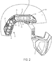
Fig. 1 is a front, side perspective view of a mounting rail assembly in accordance with an exemplary embodiment of the present invention coupled to a helmet and an accessory device; -
Fig. 2 is a right side elevational view of the mounting rail assembly ofFig. 1 ; -
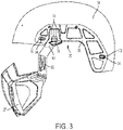
Fig. 3 is a left side elevational vide of the mounting rail assembly ofFig. 1 with the outer rail removed; -
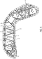
Fig. 4 is an isolated side perspective view of the shim ofFig. 1 ; -
Fig. 5 is an isolated rear elevational view of the rail ofFig. 1 ; -
Fig. 6 is a top perspective view of the mounting rail assembly ofFig. 1 ; -
Fig. 7 is a front, side perspective view of the mandible shield shown inFig. 1 ; -
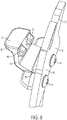
Fig. 8 is a close-up front perspective view of the fastener of the mandible shield shown inFig. 1 ; -
Fig. 9 is a front elevational view of the mandible shield ofFig. 1 ; -
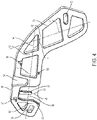
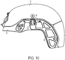
Fig. 10 is a side elevational view of the mounting rail assembly ofFig. 1 with the outer rail removed and a ballistic applique coupled to the mounting rail assembly; -
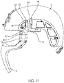
Fig. 11 is a side elevational view of a mounting rail assembly in accordance with a second embodiment of the present invention with the outer rail removed; and -
Fig. 12 is a close up side elevational view of the mounting rail assembly ofFig. 11 . - Referring to the drawings in detail, wherein like reference numerals indicate like elements throughout, there is shown in
Figs. 1-10 a mounting rail assembly, generally designated 20, in accordance with an exemplary embodiment of the present invention. The mountingrail assembly 20 may include arail 22 coupled to ahelmet 24. Therail 22 may include one or more engagement features configured to selectively couple one or more devices to thehelmet 24. As described in further detail below, the mountingrail assembly 20 may allow for one or more accessory devices to be coupled to an edge of therail 22 or an edge of the mountinggrail system 20 without blocking access to a mounting groove 29 extending along a front surface of therail 22 for coupling one or more additional accessory devices to therail 22. The one or more accessory devices coupled to therail 22 may include, for example but are not limited to, a mandible shield, a ballistic panel or applique, a visor, a goggle, a communication system, a retention system including a chin strap, a light, a camera, a helmet cover, a battery, and/or a gas supply mask. In one embodiment, the accessory device is coupled to the rail such that the device is positioned below the rail. In another embodiment, the accessory device is coupled to the rail such that the device is above or adjacent the rail. The first engagement feature may be a track, mounting groove 29, indents 23, and/oropenings 26 along an edge of therail 22 configured to receive or couple to the corresponding engagement feature of the accessory device. The second engagement feature may be a recess 36 configured to receive a fastener, as explained in greater detail below. One rail contemplated for use with embodiments the present invention where the rail is retro fitted to include additional attachment features is described inU.S. Patent No. 7,849,517 , although other rails are also contemplated. - Turning to
Figs. 1 ,3 , and4 , the mountingrail assembly 20 may include a mounting rail base plate orshim 28 and therail 22. In use, theshim 28 is configured to be coupled between thehelmet 24 and therail 22. Therail 22 may include a front surface 25 spaced a first distance from thehelmet 24 when therail 22 is coupled to thehelmet 24. The front surface 25 may be spaced a second distance from thehelmet 24 when therail 22 is coupled to theshim 28. The second distance may be greater than the first distance. Therail 22 may include a rear surface opposite the front surface 25. - The
shim 28 may be configured to couple to an existingrail 22 to add additional engagement features to therail 22. In one embodiment, theshim 28 may be selectively detached from therail 22 to return to directly coupling therail 22 to thehelmet 24. In other embodiments, theshim 28 and therail 22 are provided or sold together as a kit to allow the user to choose when to install therail 22 with theshim 28 or when to omit theshim 28. In other embodiments, theshim 28 is fixed to therail 22 such as through one way snap fit features and or adhesive not intended to be detached, or theshim 28 may be molded with therail 22 or welded to therail 22 such that the mountingrail assembly 20 is a unitary construct. - In some embodiments, the
shim 28 and therail 22 have a substantially similar, or identical, footprint. In some embodiments, theshim 28 has an outer perimeter generally shaped to match a footprint of the rail. In other embodiments, theshim 28 has a smaller footprint than therail 22. In still other embodiments, theshim 28 has a larger footprint than therail 22. Theshim 28 may prevent therail 22 from contacting thehelmet 24 when therail 22 is coupled to theshim 28 and allow for additional and improved device coupling to the rail as discussed in further detail below. - Referring to
Figs. 1 and3 , theshim 28 is sandwiched between therail 22 and thehelmet 24. To aid in keeping theshim 28 aligned with therail 22, theshim 28 may include anaperture 30 configured to receive a fastener (not shown) extending from or through thehelmet 24. The fastener may be a threaded bolt, snap, or expanding anchor. Theaperture 30 of theshim 28 may be configured to align withpre-existing rail apertures 32 andhelmet apertures 34 and be coupled to thehelmet 24 using the chin strap bolts or similar fastener. Each of theshim aperture 30 and therail aperture 32 may be aligned withhelmet apertures 34 in thehelmet 24. A single fastener may extend through each of theshim aperture 30 and therail aperture 32 to secure theshim 28 and therail 22 to the helmet. In one embodiment, the existing chin strap bolts may be used in connection with theshim 28. In other embodiments, longer chin strap bolts are provided for use with theshim 28. In other embodiments, theshim 28 may be attached to the helmet without an aperture such as by an adhesive, heat stake or weld and/or by being sandwiched between therail 22 and thehelmet 24. - The mounting
rail assembly 20 may include a recess 36 configured to receive afastener 40 of a device to couple the accessory device to the mountingrail assembly 20. The recess may be open upwardly (when positioned along a top edge of the mounting rail assembly 20) or downwardly (when positioned along a bottom edge of the mounting rail assembly 20) to receive an accessory device when theshim 28 is coupled between therail 22 and thehelmet 24. The recess 36 may be open generally perpendicular to the mounting groove 29. The recess 36 may provide an additional connection such that one accessory device can be coupled to the mounting groove 29 and a second accessory device can be coupled to the recess 36. The recess 36 may be open in a different direction than the mounting groove 29 such that accessory devices can be coupled to the mountingrail assembly 20 at different angles. The recess 36 may be closer to a top of the helmet than the mounting groove 29. The mountingrail assembly 20 may include multiple recesses 36. The recess 36 may be positioned such that the recess 36 avoids interference with the mounting groove 29 (e.g., an accessory device coupled to recess 36 may be clear of the mounting groove 29). The recess 36 may be proximate an edge of the mountingrail assembly 20. Referring toFigs. 1 ,3 , and4 , theshim 28 may include the recess 36 (seeFig. 4 ). Thefastener 40 may be a mount, a projection, a hook, a buckle, a clasp, a clip, or an attachment. The recess 36 may be configured to receive afirst portion 38 of thefastener 40. - At least a portion of the recess 36 may be positioned between the front surface 25 or the mounting groove 29 and the rear surface of the mounting
rail assembly 20. The recess 36 may be a portion of theshim 28 having a reduced thickness compared to an adjacent portion of theshim 28. The recess 36 may extend from afirst side 42 of theshim 28 toward asecond side 44 of theshim 28. Thefirst side 42 andsecond side 44 may be opposing sides of theshim 28. Thesecond side 44 may be adjacent an exterior surface of thehelmet 24 when theshim 28 is coupled to thehelmet 24. The recess 36 may be open on thefirst side 42 of theshim 28 which faces a rear side of therail 22. The recess 36 may be formed by an indent in a front surface of theshim 28 and the rear surface of therail 22. The recess 36 may open outwardly and be configured to be closed off by the rear surface of therail 22. In some embodiments, by having therail 22 close the open side of the recess 36, the thickness of theshim 28 may be reduced. In other embodiments, the recess 36 may be closed on thefirst side 42 and thesecond side 44 of theshim 28 and not reliant on therail 22 or thehelmet 24 to close the recess 36. The recess 36 may extend from thesecond surface 44 toward thefirst surface 42 such that thefastener 40 is positioned between thehelmet 24 and theshim 28 when thefastener 40 is in the recess 36. The recess 36 may extend through theshim 28 from thefirst side 42 to thesecond side 44. - The recess 36 may be defined by a
sidewall 46. The recess 36 may include a protrusion 48. The protrusion 48 may extend from asurface 50 of the recess 36 toward thefirst side 42 of theshim 28. The protrusion 48 may extend from thesidewall 46 into the recess 36. Anouter surface 52 of the protrusion 48 may be coplanar with thefirst side 42 of theshim 28. In other embodiments, theouter surface 52 of the protrusion 48 may be recessed compared to thefirst side 42 of theshim 28. - Referring to
Figs. 4 ,6 , and10 , the mountingrail assembly 20 may include asecond recess 54 configured to receive an additional accessory device. Thesecond recess 54 may be proximate an edge of the mountingrail assembly 20. Thesecond recess 54 may be open generally in an opposite direction of the recess 36. In one embodiment, the additional accessory device includes afastener 45 similar to thefastener 40. In other embodiments, the accessory device may include a first piece configured to be positioned in the second recess and a second piece that could wrap around the top of the rail and clip into theindent 23 or to the rail. Thesecond recess 54 may be a portion of theshim 28 having a reduced thickness compared to an adjacent portion of theshim 28. Thesecond recess 54 may extend from one of thefirst side 42 and thesecond side 44 of theshim 28 toward the other of thefirst side 42 and thesecond side 44. Thesecond recess 54 may extend through theshim 28 from thefirst side 42 to thesecond side 44. The mountingrail assembly 20 orshim 28 may include more than one recess 36 orsecond recess 54. Thesecond recess 54 may be formed by an indent on the front surface of theshim 28 and the rear surface of therail 22. Thefastener 45 may be coupled to a second accessory device 47 (Fig. 10 ). Thesecond accessory device 47 may be, for example but not limited to, a ballistic panel or applique, a visor, a goggle, a communication system, a retention system, a light, a camera, a helmet cover, a battery, a gas supply mask, a cable, or a cord. Thefastener 45 may help to align thesecond accessory device 47 on thehelmet 22 which may assist a user in attaching and properly aligning thesecond accessory device 47 on thehelmet 22 when the user cannot visually observe the placement of the second accessory device 47 (e.g., when the user is wearing thehelmet 22 and attaching the second accessory device 47). In one embodiment, thefastener 45 includes a clip for securing an electrical cord extending to a device mounted on the front of the helmet along the top of therail 22 and to a battery source mounted on the rear of the helmet. In some embodiments, therail 22 includes at least one of thesecond recess 54 and the recess 36 such that the rail receives thefastener 45 or the connector. Thesecond recess 54 or recess 36 may be positioned anywhere along therail 22 or theshim 28. In some embodiments, a first accessory device can be coupled to the mounting groove 29, a second accessory device can be coupled to recess 36, and a third accessory device can be coupled torecess 54. The first accessory device, second accessory device, and third accessory device may all be coupled to the mountingrail assembly 20 simultaneously while the mountingrail assembly 20 is in use. Recess 36 andrecess 54 may be sized and configured to form gaps which allowfastener 40 and/orfastener 45 to be at least partially inserted betweenhelmet 24 andrail 22 and/or betweenshim 28 andrail 22. - Referring to
Figs. 4 and5 , theshim 28 may include one or more locating features 56 configured to align therail 22 on theshim 28. Thealignment feature 56 may be a protrusion such as a peg or dowel on one of therail 22 and theshim 28 configured to engage a recess in the other of therail 22 and theshim 28. In one embodiment, thealignment feature 56 is a projection that extends away from thefirst surface 42 of theshim 28. Thealignment feature 56 may taper toward a point as thealignment feature 56 extends away from thefirst surface 42 of the shim. Thealignment feature 56 may be configured to be received in arecess 58 in therail 22. Thealignment feature 56 may be configured to be positioned adjacent an existingrail strut 60. The alignment features 56 may have differing sizes and/or shapes. Thealignment feature 56 may at least temporarily align therail 22 on theshim 28 until therail 22 and theshim 28 are fixed to the helmet. Thealignment feature 56 may also help to prevent therail 22 from sliding relative to theshim 28. In one embodiment, theshim 28 includes at least two alignment features to help prevent rotating of therail 22 relative to theshim 28. In one embodiment, theshim 28 includes three alignment features 56 spaced apart in a triangular formation. In some embodiments, therail 22 includes thealignment feature 56 and theshim 28 includes a corresponding feature to receive thealignment feature 56. - The
shim 28 may include abody 62 with a plurality ofopenings 64 extending through thebody 62. Theopenings 64 may reduce the weight of theshim 28 compared to a shim without the weight reducing openings. Thebody 62 may include struts 66 coupled to a perimeter of thebody 62. The interior and exterior surfaces of theshim 28 may have a radius of curvature configured to approximate the radius of curvature of an exterior surface of thehelmet 24. In one embodiment, theshim 28 includes a radius, before the shim is coupled to thehelmet 24, of about 2 inches (51 mm) to about 12 pinches (305 mm), about 4 inches (102 mm) to about 10 pinches (254 mm), or about 6 inches (152 mm) to about 8 inches (203 mm). Theshim 28 may be manufactured from a flexible material such that theshim 28 may flex to conform to the exterior surface of thehelmet 24. In one embodiment, theshim 28 has a radius of curvature less than the radius of curvature of the helmet but is configured to flex to conform to the exterior surface of thehelmet 24. Theshim 28 may include a first portion having afirst axis 41 and a second portion having a second axis 43. Thefirst axis 41 and the second axis 43 may be a median of the first portion and second portion, respectively. Thefirst axis 41 may be transverse to the second axis 43. Thefirst axis 41 may be perpendicular to the second axis 43. An angle α between thefirst axis 41 and the second axis 43 may be about 60 degrees to about 120 degrees, about 70 degrees to about 110 degrees, about 80 degrees to about 100 degrees, about 70 degrees, about 80 degrees, about 90 degrees, about 100 degrees, about 110 degrees, about 120 degrees, about 130 degrees, about 140 degrees, or about 180 degrees. - The
shim 28 may be manufactured from carbon fiber. In other embodiments, theshim 28 may be manufactured from plastic such as ABS (acrylonitrile butadiene styrene), nylon, or polycarbonate. Theshim 28 may be comprised of a material and/or include a surface roughness configured to increase the friction between the helmet and therail 22. In still other embodiments, theshim 28 may be manufactured from carbon fiber or sheet metal (e.g., aluminum, steel, or titanium). Theshim 28 may include a thickness between thefirst side 42 and thesecond side 44 of theshim 28. The thickness may be selected such that the recess 36 may accommodate thefastener 40 and/or thesecond recess 54 can accommodate the connector. In one embodiment, theshim 28 and therail 22 have the same thickness. In another embodiment, theshim 28 is thicker than therail 22. Theshim 28 may have a thickness of about 1 millimeter to about 8 millimeters, about 3 millimeters to about 6 millimeters, or about 4 millimeters. - Referring to
Figs. 2 and3 , therail 22 may extend between existing bolt holes or helmet apertures 34 (helmet apertures 34 best seen inFig. 3 ). Therail 22 may be bent such that the rail follows a contour of thehelmet 24. Therail 22 may include afirst portion 35 and asecond portion 37. Thefirst portion 35 may be transverse to thesecond portion 37. The rail may include aconnector 39 between thefirst portion 35 and thesecond portion 37. Theconnector 39 may be configured to couple to an accessory device (not shown). Theconnector 39 may be a buckle, clasp, or hook. Therail 28 may extend along an edge (e.g., a lower edge) of thehelmet 24. Therail 22 may include atop edge 31 and alower edge 33. Thelower edge 33 may extend along a lower edge of thehelmet 24. Therail 22 may include a mounting groove 29 between thetop edge 31 and thelower edge 33 of therail 22. The mounting groove 29 may be configured to receive a connector coupled to an accessory device (not shown). The mounting groove 29 may be open such that the connector coupled to an accessory device can slide along the length of the mounting groove 29 and be coupled to the accessory device at two or more positions along the length of therail 22. At least one of thetop edge 31 and thelower edge 33 may be parallel with the mounting groove 29. The recess 36 may be along thetop edge 31 orlower edge 33 edge. The recess 36 may be positioned somewhere along the length of the mounting groove 29. The recess 36 may be open in a direction generally perpendicular to the opening of mounting groove 29. - Referring to
Figs. 3 ,7 , and8 , thefastener 40 may include asecond portion 68 coupled to thedevice 27. Thedevice 27 may be a mandible shield (such as the one shown), a mask, a visor, a goggle, a communication system, a retention system, a light, a camera, a helmet cover, a battery, a cable, or a cord. A first device may be coupled to thesecond portion 68 of the fastener. A second device may be coupled to the mounting groove 29. A third device may be coupled to thesecond recess 54. - In one embodiment, the recess 36 allows for a first device to be attached to the
rail 22 and for a second device to be coupled anywhere along the mounting groove 29. Thefirst portion 38 of thefastener 40 may include aprong 70 configured to be received by the recess 36. Theprong 70 may couple thefirst portion 38 of thefastener 40 to theshim 28 when theprong 70 is positioned within the recess 36. Theprong 70 may be one of a plurality ofprongs 72. The plurality ofprongs 72 may be separated by aspace 74. Thespace 74 may be configured to receive the protrusion 48 when the plurality ofprongs 72 are within the recess 36. Thespace 74 may be wider than the protrusion 48 such that the plurality ofprongs 72 maintain their alignment when thefirst portion 38 of thefastener 40 is positioned within the recess 36. In other embodiments, thespace 74 may be narrower than the protrusion 48 such that the plurality ofprongs 72 are deflected away from each other, or the protrusion 48 is compressed, when the protrusion 48 is within thespace 74. Theshim 28 may include more than one recess 36 such that theshim 28 can be coupled to more than onefastener 40. In still other embodiments, theprongs 70 may form snap fit features such as a buckle. - With continued reference to
Figs. 3 and7-8 , thefastener 40 may include anattachment arm 76 configured to engage a feature such as a recess orindent 23 of therail 22. Theattachment arm 76 may couple thefastener 40 to therail 22 when theattachment arm 76 is engaged with theindent 23. Theattachment arm 76 may be flexible to move between an engaged position and a disengaged position. Theattachment arm 76 may include a protrusion such as apeg 78 configured to engage theindent 23 on therail 22 when theattachment arm 76 is in the engaged position (peg 78 best seen inFig. 8 ). Thepeg 78 may be one of a plurality of pegs configured to engage more than oneindent 23. In one embodiment, there are twopegs 78 that are configured to engaged correspondingrecesses 23 in the rail. In one embodiment, a plurality ofpegs 78 each engaging adifferent indent 23 may at least partially prevent rotation or twisting of thefastener 40 relative to therail 22 along a plane generally parallel to the rail. Thepeg 78 may be disengaged from theindent 23 when theattachment arm 76 is in the disengaged position. Theattachment arm 76 may include atoggle 80 configured to be manually engaged to move theattachment arm 76 between the engaged position and the disengaged position. In one embodiment, thetoggle 80 is flexible and biased toward the rail when flexed away from the rail. Theattachment arm 76 may be biased toward the engaged position such that engaging thetoggle 80 moves theattachment arm 76 to the disengaged position. Thetoggle 80 may include a platform ortab 82 engageable by a user's thumb or finger. In other embodiments, thetoggle 80 may be a push-button or lever. Theattachment arm 76 may be coupled to thefastener 40 by ananchor 84. In other embodiments, theattachment arm 76 may be coupled to thefastener 40 by adhesive or welding. In still other embodiments, theattachment arm 76 and thefastener 40 may be a unitary construct. Theattachment arm 76 may include aninner surface 86 configured to abut a lower surface 88 of therail 22 when thefastener 40 is coupled to theshim 28 andrail 22. - Referring to
Fig. 9 , theattachment arm 76 andfirst portion 38 of thefastener 40 may define a channel 90 configured to receive a portion of therail 22 when thefastener 40 is coupled to theshim 28 andrail 22. A first surface (e.g., the first portion 38) of thefastener 40 may contact an inner surface of therail 22 and a second surface (e.g., the attachment arm 76) may contact an outer surface of therail 22 when thefastener 40 is coupled to therail 22. In one embodiment, thefastener 40 wraps around a top or bottom edge of therail 22. In one embodiment, thefastener 40 may be connected to thefastener 45 such that the combinedfastener 40 andfastener 45 encircle therail 22 when thefastener 40 is within the recess 36 and thefastener 45 is within thesecond recess 54. In one embodiment, the coupler (not shown) wraps around a top or bottom edge of therail 22. Thefastener 40 may be engaged and/or disengaged from theshim 28 and/orrail 22 while theshim 28 andrail 22 are coupled to thehelmet 24. Thus, thedevice 27 may be coupled or decoupled from therail 22 and/orshim 28 while therail 22 and theshim 28 are coupled to thehelmet 24. - The
shim 28 may be included in a kit configured to be coupled to existingrail 22 and helmet systems. A method of retrofitting a helmet may include obtaining ashim 28. The method of retrofitting may include detaching the existingrail 22 from the helmet. The method may include aligning therail 22 with theshim 28 by engaging thealignment feature 56 with therecess 58. The method may include securing therail 22 and theshim 28 to thehelmet 24 with an anchor. The method may include coupling thefastener 40, and thus thedevice 27, to therail 22 and/orshim 28. - Referring to
Figs. 11 and12 , there is shown a second exemplary embodiment of a mounting rail assembly, generally designated 120. The mountingrail assembly 120 is similar to the first embodiment of the mountingrail 20 except the recess of mountingrail assembly 120 may include a locking feature. - Still referring to
Figs. 11 and12 , the mountingrail assembly 120 may include afastener 140 having asecond portion 68 configured to be coupled to a device. Thefastener 140 may include afirst portion 142 configured to engage arecess 144 in theshim 128. The mountingrail assembly 120 may include arelease 148 configured to disengage thefastener 140 from therecess 144. - The
recess 144 may include asidewall 146 configured to be engaged by thefastener 140. Thesidewall 146 may include aledge 150. Theledge 150 may be perpendicular to an adjacent portion of thesidewall 146. In other embodiments theledge 150 may be oblique to the adjacent portion of thesidewall 146. Thefirst portion 142 of thefastener 140 may include anarm 156 deflectable from an engaged position to a disengaged position. Thearm 156 may include arim 158 configured to engage theledge 150 when thefastener 140 is within therecess 144. Theledge 150 and therim 158 may be parallel to each other. At least one of theledge 150 and therim 158 may be parallel to one of thefirst side 152 and thesecond side 154 of theshim 128. - The
release 148 may be selectively engageable by a user and configured to deflect thearm 156 from the engaged position to the disengaged position to disengage thefastener 140 from thesidewall 146. Therelease 148 may include arelease engagement surface 160 configured to engage anarm engagement surface 162. At least one of therelease engagement surface 160 and thearm engagement surface 162 may include an angled surface such that relative axial movement between therelease engagement surface 160 and thearm engagement surface 162 causes transverse movement of thearm 156. Therelease 148 may be moveable relative to theshim 128. In one embodiment, thearm engagement surface 162 is obliquely angled relative to an axis along which therelease 148 moves relative to theshim 128. In one embodiment, therelease 148 may be slideable within therecess 144. In other embodiments, therelease 148 may include a cam such that rotation of therelease 148 disengages thefastener 140 from thesidewall 146. Therelease engagement surface 160 may engage thearm engagement surface 162 as therelease 148 is moved relative to theshim 128 and disengage thefastener 140 from thesidewall 146. In one embodiment, movement of therelease 148 may deflect the arm to the disengaged position, thereby disengaging therim 158 from theledge 150 such that thefastener 140 may be removed from therecess 144. The release may be moveably coupled to theshim 128. Anend 170 of therelease 148 may be positioned above thesecond side 154 of theshim 128 when thefastener 140 is in therecess 144. In other embodiments, theend 170 of therelease 148 may be co-planar or below thesecond side 154 of theshim 128 when thefastener 140 is in therecess 144. Therecess 144 may extend from afirst side 152 of theshim 128 to asecond side 154 of theshim 128. - The
first portion 142 of thefastener 140 may include abrace 164 configured to maintain the position of thefastener 140 in therecess 144 when therelease 148 is moved relative to theshim 128. Thebrace 164 may prevent lateral movement of thefastener 140 when therelease 148 engages thearm 156. Thebrace 164 may assist in aligning thefastener 140 within therecess 144 during insertion of thefastener 140. Therecess 144 may include aprotrusion 166 configured to be positioned between thearm 156 and thebrace 164 when thefastener 140 is within therecess 144. Thefastener 140 may include a base 168 configured to abut an edge of theshim 128 and/orrail 22 when thefastener 140 is within therecess 144. Thefastener 140 may be between theshim 128 and therail 22 when thefastener 140 is within therecess 144. Thefastener 140 may be between theshim 128 and thehelmet 24 when thefastener 140 is within therecess 144. - It will be appreciated by those skilled in the art that changes could be made to the exemplary embodiments shown and described above. It is understood, therefore, that this invention is not limited to the exemplary embodiments shown and described, but it is intended to cover modifications within the scope of the present invention as defined by the claims. The words "right", "left", "lower" and "upper" designate directions in the drawings to which reference is made. The words "inwardly" and "outwardly" refer to directions toward and away from, respectively, the geometric center of the mounting rail base plate. Unless specifically set forth herein, the terms "a", "an" and "the" are not limited to one element but instead should be read as meaning "at least one".
- It is to be understood that at least some of the figures and descriptions of the invention have been simplified to focus on elements that are relevant for a clear understanding of the invention, while eliminating, for purposes of clarity, other elements that those of ordinary skill in the art will appreciate may also comprise a portion of the invention. However, because such elements are well known in the art, and because they do not necessarily facilitate a better understanding of the invention, a description of such elements is not provided herein.
Claims (19)
- A mounting rail assembly (20) comprising:a rail (22) configured to be coupled to a helmet (24), the rail including a front surface (25) with a mounting groove (29) extending along a length of the front surface, the mounting groove open outwardly from the front surface of the rail and configured to couple to a first accessory device at two or more positions along the length of the rail; charcterized bya shim (28) located between the helmet and the rail and forming at least a portion of a recess, whereinthe recess (36) is proximate an edge of the mounting rail assembly open generally perpendicular to the mounting groove, the recess open upwardly to receive a second accessory device (47) when the shim is coupled between the rail and the helmet, at least a portion of the recess positioned between the mounting groove and a rear surface of the mounting rail assembly.
- The mounting rail assembly of claim 1, wherein the shim (28) is selectively detached from the rail (22) to directly couple the rail (22) to the helmet (24).
- The mounting rail assembly of claim 1, wherein the shim (38) is fixed to the rail (22) such that the mounting rail assembly (20) is a unitary construct.
- The mounting rail assembly (20) of claim 2, wherein the shim (28) further comprises an outer perimeter generally shaped to match a footprint of the rail (22)., and wherein
the recess open outwardly and configured to be closed off by the rail. - The mounting rail assembly of claim 4, wherein the recess is formed by an indent in a front surface (28) of the shim and the rear surface of the rail (22).
- The mounting rail assembly (20) of any preceding claim, further comprising:
a fastener (40) having a first portion (38) configured to be positioned at least partially within the recess (36) and a second portion (68) configured to be coupled to the second accessory device (47). - The mounting rail assembly (20) of claim 6, wherein the recess (36) includes a protrusion (48) and the fastener (40) includes a plurality of prongs (72) separated by a space, and
wherein the protrusion is configured to be positioned within the space when the plurality of prongs are within the recess. - The mounting rail assembly (20) of claim 6 or claim 7, wherein:the rail (22) includes at least one indent (23) below the mounting groove, andthe fastener (40) includes an attachment arm (76) configured to engage the at least one indent to further couple the fastener to the mounting rail assembly when the fastener is positioned at least partially within the recess (36).
- The mountain rail assembly of claim 6,, wherein the attachment arm includes at least one peg (78) configured to engage the at least one indent when the attachment arm is in the engaged position.
- The mounting rail assembly (20) of any preceding claim, further comprising the second accessory device (47), the second accessory device including one or more of a mandible shield, a communication system, a gas supply mask, and a chin strap.
- The mounting rail assembly (20) of any one of claims 6 to 10, wherein the recess includes a first recess (36), the mounting rail assembly further comprising:
a second recess (54) proximate the edge of the mounting rail assembly, open generally in an opposite direction of the first recess, and configured to receive a third accessory device. - The mountain rail assembly of claim 11, further comprising the third accessory device, the third accessory device including one or more of a ballistic panel or applique, a visor, a goggle, a communication system, a retention system, a light, a camera, a helmet cover, a battery, a gas supply mask, a cable, and a cord.
- The mounting rail assembly (20) of any preceding claim, wherein the shim (28) is configured to flex to conform to a shape of an exterior surface of the helmet (24); and/or, wherein the shim includes an aperture (30) configured to align with existing apertures (32) in the rail (22).
- The mounting rail assembly (20) of any preceding claim, wherein either the shim further comprises:at least two alignment projections (56) extending from a front surface (28) of the shim configured to extend into a corresponding feature on the rail (22) to align the rail with the shim; and/or.wherein the shim includes a first portion including a first axis (41) and a second portion including a second axis (43), andwherein the first axis is transverse to the second axis.
- The mounting rail assembly (20) of any claim directly or indirectly dependent on claim 5, wherein the shim (28) includes a body (62) with a plurality of openings extending through the body; and/or, wherein the mounting rail assembly is a unitary construct including the shim and the rail (22).
- The mounting rail assembly (20) of claim 6, wherein the recess (36) includes a sidewall (46) and the mounting rail assembly includes a release (148) selectively engageable by a user to disengage the fastener (40) from the sidewall.
- The mounting rail assembly (20) of claim 16, wherein the fastener includes a deflectable arm and the release is configured to deflect the deflectable arm to disengage the fastener from the sidewall and to disengage the second accessory device (47) from the recess (36).
- The mounting rail assembly (20) of claim 17, wherein the sidewall (46) includes a ledge (150) and the deflectable arm includes a rim configured to engage the ledge when the fastener (40) is within the recess (36).
- The mounting rail assembly (20) of claim 17 or claim 18, wherein the fastener (40) includes a brace (164) configured to maintain the position of the fastener in the recess (36) when the release is moved relative to the shim (28).
Priority Applications (1)
| Application Number | Priority Date | Filing Date | Title |
|---|---|---|---|
| EP22191349.4A EP4186383A1 (en) | 2017-03-13 | 2018-03-13 | Mounting rail |
Applications Claiming Priority (2)
| Application Number | Priority Date | Filing Date | Title |
|---|---|---|---|
| US201762470630P | 2017-03-13 | 2017-03-13 | |
| PCT/US2018/022221 WO2018169984A1 (en) | 2017-03-13 | 2018-03-13 | Mounting rail assembly |
Related Child Applications (1)
| Application Number | Title | Priority Date | Filing Date |
|---|---|---|---|
| EP22191349.4A Division EP4186383A1 (en) | 2017-03-13 | 2018-03-13 | Mounting rail |
Publications (3)
| Publication Number | Publication Date |
|---|---|
| EP3595472A1 EP3595472A1 (en) | 2020-01-22 |
| EP3595472A4 EP3595472A4 (en) | 2020-12-16 |
| EP3595472B1 true EP3595472B1 (en) | 2022-08-24 |
Family
ID=63523335
Family Applications (2)
| Application Number | Title | Priority Date | Filing Date |
|---|---|---|---|
| EP22191349.4A Pending EP4186383A1 (en) | 2017-03-13 | 2018-03-13 | Mounting rail |
| EP18766676.3A Active EP3595472B1 (en) | 2017-03-13 | 2018-03-13 | Mounting rail assembly |
Family Applications Before (1)
| Application Number | Title | Priority Date | Filing Date |
|---|---|---|---|
| EP22191349.4A Pending EP4186383A1 (en) | 2017-03-13 | 2018-03-13 | Mounting rail |
Country Status (7)
| Country | Link |
|---|---|
| US (4) | US10765165B2 (en) |
| EP (2) | EP4186383A1 (en) |
| AU (1) | AU2018236209B2 (en) |
| CA (1) | CA3054446C (en) |
| IL (1) | IL268908B2 (en) |
| PL (1) | PL3595472T3 (en) |
| WO (1) | WO2018169984A1 (en) |
Families Citing this family (8)
| Publication number | Priority date | Publication date | Assignee | Title |
|---|---|---|---|---|
| USD750846S1 (en) * | 2006-02-09 | 2016-03-01 | Artisent, Llc | Helmet mounted rail |
| WO2018169981A1 (en) * | 2017-03-13 | 2018-09-20 | Gentex Corporation | Modular shroud |
| EP4186383A1 (en) * | 2017-03-13 | 2023-05-31 | Gentex Corporation | Mounting rail |
| US10912344B2 (en) | 2018-12-03 | 2021-02-09 | Msa Technology, Llc | Helmet with accessory attachment rail |
| USD937497S1 (en) * | 2019-01-18 | 2021-11-30 | Gentex Corporation | Mandible shield |
| USD944461S1 (en) * | 2019-01-18 | 2022-02-22 | Gentex Corporation | Mandible shield |
| KR20220032521A (en) | 2019-05-22 | 2022-03-15 | 젠텍스코오포레이션 | helmet accessory mounting system |
| USD900407S1 (en) * | 2020-05-22 | 2020-10-27 | Gentex Corporation | Helmet accessory mounting system |
Family Cites Families (26)
| Publication number | Priority date | Publication date | Assignee | Title |
|---|---|---|---|---|
| US3839738A (en) | 1973-01-22 | 1974-10-08 | J Coslett | Helmet strap |
| US4442551A (en) | 1982-12-22 | 1984-04-17 | Hellberg Protection Ab | Adapter for a protective helmet |
| FR2708428B1 (en) * | 1992-12-22 | 1995-09-01 | Sextant Avionique | Protective helmet fitted with optronic systems and adjustment process. |
| US6472776B1 (en) * | 2000-03-30 | 2002-10-29 | Norotos, Inc. | Helmet mount for night vision device |
| US7908667B2 (en) * | 2005-06-17 | 2011-03-22 | Artisent, Inc. | Mounting system for accessories on a safety helmet |
| US7849517B2 (en) | 2005-06-17 | 2010-12-14 | Artisent, Inc. | Mounting system for accessories on a safety helmet |
| US20090083890A1 (en) * | 2007-08-31 | 2009-04-02 | Bae Systems Aerospace And Defense Group, Inc. | Headborne Integration System |
| WO2010037214A1 (en) | 2008-10-02 | 2010-04-08 | Eye Tactical Inc. | Adaptor platform for helmet |
| EP2473075B1 (en) * | 2009-09-03 | 2017-11-08 | Revision Military S.à.r.l. | Ballistic and impact protective visor system for military helmet assembly |
| US8984665B2 (en) | 2010-02-02 | 2015-03-24 | Wilcox Industries Corp. | Helmet mounting system and mounting shoe interface |
| WO2013006204A1 (en) | 2011-07-02 | 2013-01-10 | Sam Matthews | A quick release buckle having a single finger release capability |
| US20130191967A1 (en) * | 2012-01-31 | 2013-08-01 | Angel 7 Industries, Llc | Accessory Platform for a Helmet |
| EP2861090B1 (en) | 2012-06-18 | 2019-02-27 | Gentex Corporation | Helmet cover assembly having at least one mounting device |
| US9700096B2 (en) * | 2012-07-31 | 2017-07-11 | Revision Military S.A.R.L. | Mandible guard attachment system |
| JP6239236B2 (en) | 2013-01-15 | 2017-11-29 | 治利 渡辺 | Welding surface |
| US9788593B2 (en) * | 2013-11-18 | 2017-10-17 | Revision Military S.A.R.L. | Mandible guard adjustment system |
| US20150189939A1 (en) | 2014-01-07 | 2015-07-09 | Armorsource Llc | Accessory attachment bar and method for securing same to helmet |
| WO2015156864A2 (en) | 2014-01-14 | 2015-10-15 | Artisent, Llc | Mandible shield |
| BR102014021868B1 (en) | 2014-09-04 | 2022-02-01 | Msa Do Brasil Equipamentos E Instrumentos De Segurança Ltda | Support for mounting at least one lighting element on a hardhat, adjustable lighting system and cable retention arrangement |
| USD766521S1 (en) | 2014-10-09 | 2016-09-13 | Artisent, Llc | Helmet mounted rail |
| WO2016057792A1 (en) * | 2014-10-09 | 2016-04-14 | Artisent, Llc | Helmet mounted visor |
| US11150055B2 (en) | 2015-10-09 | 2021-10-19 | Avon Protection Ceradyne Llc | Accessory mounting device and system using same |
| US11103021B2 (en) * | 2016-05-25 | 2021-08-31 | Safariland, Llc | Headset with dual battery compartment |
| US20180192726A1 (en) * | 2017-01-10 | 2018-07-12 | Hmount Ltd | Plastic helmet mounting assembly |
| US10959473B2 (en) * | 2017-01-10 | 2021-03-30 | Hmount Ltd | Plastic helmet mounting assembly |
| EP4186383A1 (en) * | 2017-03-13 | 2023-05-31 | Gentex Corporation | Mounting rail |
-
2018
- 2018-03-13 EP EP22191349.4A patent/EP4186383A1/en active Pending
- 2018-03-13 IL IL268908A patent/IL268908B2/en unknown
- 2018-03-13 US US16/493,587 patent/US10765165B2/en active Active
- 2018-03-13 CA CA3054446A patent/CA3054446C/en active Active
- 2018-03-13 PL PL18766676.3T patent/PL3595472T3/en unknown
- 2018-03-13 EP EP18766676.3A patent/EP3595472B1/en active Active
- 2018-03-13 AU AU2018236209A patent/AU2018236209B2/en active Active
- 2018-03-13 WO PCT/US2018/022221 patent/WO2018169984A1/en unknown
-
2020
- 2020-07-29 US US16/942,083 patent/US11528951B2/en active Active
-
2022
- 2022-11-17 US US18/056,357 patent/US11889879B2/en active Active
-
2023
- 2023-12-06 US US18/530,785 patent/US20240108092A1/en active Pending
Also Published As
| Publication number | Publication date |
|---|---|
| IL268908B (en) | 2022-11-01 |
| US20200077732A1 (en) | 2020-03-12 |
| EP4186383A1 (en) | 2023-05-31 |
| US20230079947A1 (en) | 2023-03-16 |
| EP3595472A4 (en) | 2020-12-16 |
| IL268908A (en) | 2019-10-31 |
| PL3595472T3 (en) | 2022-11-21 |
| EP3595472A1 (en) | 2020-01-22 |
| CA3054446A1 (en) | 2018-09-20 |
| US20240108092A1 (en) | 2024-04-04 |
| AU2018236209B2 (en) | 2020-08-13 |
| AU2018236209A1 (en) | 2019-09-19 |
| US11889879B2 (en) | 2024-02-06 |
| US10765165B2 (en) | 2020-09-08 |
| US11528951B2 (en) | 2022-12-20 |
| IL268908B2 (en) | 2023-03-01 |
| US20200352269A1 (en) | 2020-11-12 |
| WO2018169984A1 (en) | 2018-09-20 |
| CA3054446C (en) | 2022-03-15 |
Similar Documents
| Publication | Publication Date | Title |
|---|---|---|
| EP3595472B1 (en) | Mounting rail assembly | |
| US11246367B2 (en) | Mounting system for accessories on a safety helmet | |
| US9717294B2 (en) | Hinged attachment of headgear to a helmet | |
| US7908667B2 (en) | Mounting system for accessories on a safety helmet | |
| US7849517B2 (en) | Mounting system for accessories on a safety helmet | |
| US8209784B2 (en) | Helmet with an attachment mechanism for a faceguard | |
| US11382375B2 (en) | Modular shroud | |
| US11547167B2 (en) | Protection attachment for a helmet | |
| EP2806759B1 (en) | Helmet earpiece | |
| US20130000016A1 (en) | Helmet Retention System | |
| US9398781B1 (en) | Headgear appliance mounting and retention system |
Legal Events
| Date | Code | Title | Description |
|---|---|---|---|
| STAA | Information on the status of an ep patent application or granted ep patent |
Free format text: STATUS: THE INTERNATIONAL PUBLICATION HAS BEEN MADE |
|
| PUAI | Public reference made under article 153(3) epc to a published international application that has entered the european phase |
Free format text: ORIGINAL CODE: 0009012 |
|
| STAA | Information on the status of an ep patent application or granted ep patent |
Free format text: STATUS: REQUEST FOR EXAMINATION WAS MADE |
|
| 17P | Request for examination filed |
Effective date: 20190911 |
|
| AK | Designated contracting states |
Kind code of ref document: A1 Designated state(s): AL AT BE BG CH CY CZ DE DK EE ES FI FR GB GR HR HU IE IS IT LI LT LU LV MC MK MT NL NO PL PT RO RS SE SI SK SM TR |
|
| AX | Request for extension of the european patent |
Extension state: BA ME |
|
| DAV | Request for validation of the european patent (deleted) | ||
| DAX | Request for extension of the european patent (deleted) | ||
| REG | Reference to a national code |
Ref country code: HK Ref legal event code: DE Ref document number: 40014233 Country of ref document: HK |
|
| REG | Reference to a national code |
Ref country code: DE Ref legal event code: R079 Ref document number: 602018039745 Country of ref document: DE Free format text: PREVIOUS MAIN CLASS: A42B0003000000 Ipc: A42B0003040000 |
|
| A4 | Supplementary search report drawn up and despatched |
Effective date: 20201117 |
|
| RIC1 | Information provided on ipc code assigned before grant |
Ipc: A62B 18/08 20060101ALI20201111BHEP Ipc: A42B 3/04 20060101AFI20201111BHEP |
|
| STAA | Information on the status of an ep patent application or granted ep patent |
Free format text: STATUS: EXAMINATION IS IN PROGRESS |
|
| 17Q | First examination report despatched |
Effective date: 20211020 |
|
| GRAP | Despatch of communication of intention to grant a patent |
Free format text: ORIGINAL CODE: EPIDOSNIGR1 |
|
| STAA | Information on the status of an ep patent application or granted ep patent |
Free format text: STATUS: GRANT OF PATENT IS INTENDED |
|
| INTG | Intention to grant announced |
Effective date: 20220309 |
|
| RAP3 | Party data changed (applicant data changed or rights of an application transferred) |
Owner name: GENTEX CORPORATION |
|
| GRAS | Grant fee paid |
Free format text: ORIGINAL CODE: EPIDOSNIGR3 |
|
| GRAA | (expected) grant |
Free format text: ORIGINAL CODE: 0009210 |
|
| STAA | Information on the status of an ep patent application or granted ep patent |
Free format text: STATUS: THE PATENT HAS BEEN GRANTED |
|
| AK | Designated contracting states |
Kind code of ref document: B1 Designated state(s): AL AT BE BG CH CY CZ DE DK EE ES FI FR GB GR HR HU IE IS IT LI LT LU LV MC MK MT NL NO PL PT RO RS SE SI SK SM TR |
|
| REG | Reference to a national code |
Ref country code: CH Ref legal event code: EP |
|
| REG | Reference to a national code |
Ref country code: IE Ref legal event code: FG4D |
|
| REG | Reference to a national code |
Ref country code: AT Ref legal event code: REF Ref document number: 1513063 Country of ref document: AT Kind code of ref document: T Effective date: 20220915 Ref country code: DE Ref legal event code: R096 Ref document number: 602018039745 Country of ref document: DE |
|
| REG | Reference to a national code |
Ref country code: NO Ref legal event code: T2 Effective date: 20220824 |
|
| REG | Reference to a national code |
Ref country code: LT Ref legal event code: MG9D |
|
| REG | Reference to a national code |
Ref country code: NL Ref legal event code: MP Effective date: 20220824 |
|
| PG25 | Lapsed in a contracting state [announced via postgrant information from national office to epo] |
Ref country code: SE Free format text: LAPSE BECAUSE OF FAILURE TO SUBMIT A TRANSLATION OF THE DESCRIPTION OR TO PAY THE FEE WITHIN THE PRESCRIBED TIME-LIMIT Effective date: 20220824 Ref country code: RS Free format text: LAPSE BECAUSE OF FAILURE TO SUBMIT A TRANSLATION OF THE DESCRIPTION OR TO PAY THE FEE WITHIN THE PRESCRIBED TIME-LIMIT Effective date: 20220824 Ref country code: PT Free format text: LAPSE BECAUSE OF FAILURE TO SUBMIT A TRANSLATION OF THE DESCRIPTION OR TO PAY THE FEE WITHIN THE PRESCRIBED TIME-LIMIT Effective date: 20221226 Ref country code: NL Free format text: LAPSE BECAUSE OF FAILURE TO SUBMIT A TRANSLATION OF THE DESCRIPTION OR TO PAY THE FEE WITHIN THE PRESCRIBED TIME-LIMIT Effective date: 20220824 Ref country code: LV Free format text: LAPSE BECAUSE OF FAILURE TO SUBMIT A TRANSLATION OF THE DESCRIPTION OR TO PAY THE FEE WITHIN THE PRESCRIBED TIME-LIMIT Effective date: 20220824 Ref country code: LT Free format text: LAPSE BECAUSE OF FAILURE TO SUBMIT A TRANSLATION OF THE DESCRIPTION OR TO PAY THE FEE WITHIN THE PRESCRIBED TIME-LIMIT Effective date: 20220824 Ref country code: FI Free format text: LAPSE BECAUSE OF FAILURE TO SUBMIT A TRANSLATION OF THE DESCRIPTION OR TO PAY THE FEE WITHIN THE PRESCRIBED TIME-LIMIT Effective date: 20220824 |
|
| PG25 | Lapsed in a contracting state [announced via postgrant information from national office to epo] |
Ref country code: IS Free format text: LAPSE BECAUSE OF FAILURE TO SUBMIT A TRANSLATION OF THE DESCRIPTION OR TO PAY THE FEE WITHIN THE PRESCRIBED TIME-LIMIT Effective date: 20221224 Ref country code: HR Free format text: LAPSE BECAUSE OF FAILURE TO SUBMIT A TRANSLATION OF THE DESCRIPTION OR TO PAY THE FEE WITHIN THE PRESCRIBED TIME-LIMIT Effective date: 20220824 Ref country code: GR Free format text: LAPSE BECAUSE OF FAILURE TO SUBMIT A TRANSLATION OF THE DESCRIPTION OR TO PAY THE FEE WITHIN THE PRESCRIBED TIME-LIMIT Effective date: 20221125 |
|
| PGFP | Annual fee paid to national office [announced via postgrant information from national office to epo] |
Ref country code: PL Payment date: 20221230 Year of fee payment: 6 |
|
| REG | Reference to a national code |
Ref country code: NO Ref legal event code: CREP |
|
| PG25 | Lapsed in a contracting state [announced via postgrant information from national office to epo] |
Ref country code: SM Free format text: LAPSE BECAUSE OF FAILURE TO SUBMIT A TRANSLATION OF THE DESCRIPTION OR TO PAY THE FEE WITHIN THE PRESCRIBED TIME-LIMIT Effective date: 20220824 Ref country code: RO Free format text: LAPSE BECAUSE OF FAILURE TO SUBMIT A TRANSLATION OF THE DESCRIPTION OR TO PAY THE FEE WITHIN THE PRESCRIBED TIME-LIMIT Effective date: 20220824 Ref country code: ES Free format text: LAPSE BECAUSE OF FAILURE TO SUBMIT A TRANSLATION OF THE DESCRIPTION OR TO PAY THE FEE WITHIN THE PRESCRIBED TIME-LIMIT Effective date: 20220824 Ref country code: DK Free format text: LAPSE BECAUSE OF FAILURE TO SUBMIT A TRANSLATION OF THE DESCRIPTION OR TO PAY THE FEE WITHIN THE PRESCRIBED TIME-LIMIT Effective date: 20220824 Ref country code: CZ Free format text: LAPSE BECAUSE OF FAILURE TO SUBMIT A TRANSLATION OF THE DESCRIPTION OR TO PAY THE FEE WITHIN THE PRESCRIBED TIME-LIMIT Effective date: 20220824 |
|
| PGFP | Annual fee paid to national office [announced via postgrant information from national office to epo] |
Ref country code: NO Payment date: 20230309 Year of fee payment: 6 Ref country code: IE Payment date: 20230110 Year of fee payment: 6 Ref country code: AT Payment date: 20230227 Year of fee payment: 6 |
|
| REG | Reference to a national code |
Ref country code: NO Ref legal event code: CREP Representative=s name: ACAPO AS, EDVARD GRIEGS VEI 1, 5059 BERGEN, NORGE |
|
| REG | Reference to a national code |
Ref country code: DE Ref legal event code: R026 Ref document number: 602018039745 Country of ref document: DE |
|
| PLBI | Opposition filed |
Free format text: ORIGINAL CODE: 0009260 |
|
| PG25 | Lapsed in a contracting state [announced via postgrant information from national office to epo] |
Ref country code: SK Free format text: LAPSE BECAUSE OF FAILURE TO SUBMIT A TRANSLATION OF THE DESCRIPTION OR TO PAY THE FEE WITHIN THE PRESCRIBED TIME-LIMIT Effective date: 20220824 Ref country code: EE Free format text: LAPSE BECAUSE OF FAILURE TO SUBMIT A TRANSLATION OF THE DESCRIPTION OR TO PAY THE FEE WITHIN THE PRESCRIBED TIME-LIMIT Effective date: 20220824 |
|
| PGFP | Annual fee paid to national office [announced via postgrant information from national office to epo] |
Ref country code: GB Payment date: 20230119 Year of fee payment: 6 Ref country code: DE Payment date: 20230117 Year of fee payment: 6 Ref country code: BE Payment date: 20230216 Year of fee payment: 6 |
|
| P01 | Opt-out of the competence of the unified patent court (upc) registered |
Effective date: 20230509 |
|
| PLAX | Notice of opposition and request to file observation + time limit sent |
Free format text: ORIGINAL CODE: EPIDOSNOBS2 |
|
| 26 | Opposition filed |
Opponent name: HEXONIA GMBH Effective date: 20230523 |
|
| PG25 | Lapsed in a contracting state [announced via postgrant information from national office to epo] |
Ref country code: AL Free format text: LAPSE BECAUSE OF FAILURE TO SUBMIT A TRANSLATION OF THE DESCRIPTION OR TO PAY THE FEE WITHIN THE PRESCRIBED TIME-LIMIT Effective date: 20220824 |
|
| PGFP | Annual fee paid to national office [announced via postgrant information from national office to epo] |
Ref country code: CH Payment date: 20230401 Year of fee payment: 6 |
|
| PG25 | Lapsed in a contracting state [announced via postgrant information from national office to epo] |
Ref country code: SI Free format text: LAPSE BECAUSE OF FAILURE TO SUBMIT A TRANSLATION OF THE DESCRIPTION OR TO PAY THE FEE WITHIN THE PRESCRIBED TIME-LIMIT Effective date: 20220824 |
|
| PLBB | Reply of patent proprietor to notice(s) of opposition received |
Free format text: ORIGINAL CODE: EPIDOSNOBS3 |
|
| PG25 | Lapsed in a contracting state [announced via postgrant information from national office to epo] |
Ref country code: MC Free format text: LAPSE BECAUSE OF FAILURE TO SUBMIT A TRANSLATION OF THE DESCRIPTION OR TO PAY THE FEE WITHIN THE PRESCRIBED TIME-LIMIT Effective date: 20220824 |
|
| PG25 | Lapsed in a contracting state [announced via postgrant information from national office to epo] |
Ref country code: LU Free format text: LAPSE BECAUSE OF NON-PAYMENT OF DUE FEES Effective date: 20230313 |
|
| PGFP | Annual fee paid to national office [announced via postgrant information from national office to epo] |
Ref country code: FR Payment date: 20231229 Year of fee payment: 7 |
|
| PGFP | Annual fee paid to national office [announced via postgrant information from national office to epo] |
Ref country code: PL Payment date: 20231229 Year of fee payment: 7 |