EP4061107A1 - Bulk feeder and component mounting machine - Google Patents
Bulk feeder and component mounting machine Download PDFInfo
- Publication number
- EP4061107A1 EP4061107A1 EP19952259.0A EP19952259A EP4061107A1 EP 4061107 A1 EP4061107 A1 EP 4061107A1 EP 19952259 A EP19952259 A EP 19952259A EP 4061107 A1 EP4061107 A1 EP 4061107A1
- Authority
- EP
- European Patent Office
- Prior art keywords
- components
- component
- bulk feeder
- feeder
- control device
- Prior art date
- Legal status (The legal status is an assumption and is not a legal conclusion. Google has not performed a legal analysis and makes no representation as to the accuracy of the status listed.)
- Granted
Links
Images




Classifications
-
- H—ELECTRICITY
- H05—ELECTRIC TECHNIQUES NOT OTHERWISE PROVIDED FOR
- H05K—PRINTED CIRCUITS; CASINGS OR CONSTRUCTIONAL DETAILS OF ELECTRIC APPARATUS; MANUFACTURE OF ASSEMBLAGES OF ELECTRICAL COMPONENTS
- H05K13/00—Apparatus or processes specially adapted for manufacturing or adjusting assemblages of electric components
- H05K13/02—Feeding of components
- H05K13/028—Simultaneously loading a plurality of loose objects, e.g. by means of vibrations, pressure differences, magnetic fields
-
- G—PHYSICS
- G06—COMPUTING OR CALCULATING; COUNTING
- G06T—IMAGE DATA PROCESSING OR GENERATION, IN GENERAL
- G06T1/00—General purpose image data processing
- G06T1/0007—Image acquisition
-
- H—ELECTRICITY
- H05—ELECTRIC TECHNIQUES NOT OTHERWISE PROVIDED FOR
- H05K—PRINTED CIRCUITS; CASINGS OR CONSTRUCTIONAL DETAILS OF ELECTRIC APPARATUS; MANUFACTURE OF ASSEMBLAGES OF ELECTRICAL COMPONENTS
- H05K13/00—Apparatus or processes specially adapted for manufacturing or adjusting assemblages of electric components
- H05K13/04—Mounting of components, e.g. of leadless components
- H05K13/043—Feeding one by one by other means than belts
-
- H—ELECTRICITY
- H05—ELECTRIC TECHNIQUES NOT OTHERWISE PROVIDED FOR
- H05K—PRINTED CIRCUITS; CASINGS OR CONSTRUCTIONAL DETAILS OF ELECTRIC APPARATUS; MANUFACTURE OF ASSEMBLAGES OF ELECTRICAL COMPONENTS
- H05K13/00—Apparatus or processes specially adapted for manufacturing or adjusting assemblages of electric components
- H05K13/08—Monitoring manufacture of assemblages
- H05K13/081—Integration of optical monitoring devices in assembly lines; Processes using optical monitoring devices specially adapted for controlling devices or machines in assembly lines
- H05K13/0813—Controlling of single components prior to mounting, e.g. orientation, component geometry
Definitions
- the present invention relates to a bulk feeder and a component mounting machine.
- a bulk feeder is mounted on a component mounting machine that mounts components on a board, and is used for supplying the components accommodated in a bulk state.
- a type of bulk feeder in which multiple components are supplied in a state of being aligned in a row by an alignment mechanism provided on a conveyance path, for example.
- the alignment mechanism as described above is omitted and the components are supplied in the bulk state in which the components are scattered in a supply region where the components can be collected by a suction nozzle.
- Patent Literature 1 JP-A-2011-114084
- the component mounting machine recognizes the supply state of the components by using the image data acquired by imaging the supply region.
- the image processing it is necessary to determine whether the component can be collected for each of multiple components, and to calculate the position and the angle of the components in a case where the components can be collected. Therefore, there is a concern that the load of the image processing will be increased.
- the bulk feeder is particularly desired to reduce a size in a width direction.
- the present description is to provide a bulk feeder capable of suitably supplying multiple components while reducing a size in a width direction and reducing a load of recognition processing of a supply state of the components in a supply region, and a component mounting machine including the bulk feeder described above.
- the present description discloses a bulk feeder including a feeder main body, a track member provided in the feeder main body and having a reception region in which multiple components discharged from a component case accommodating the components in a bulk state are received, a supply region to which the components are supplied, and a conveyance path of the components from the reception region to the supply region, a vibration device provided in the feeder main body and configured to apply vibration to the track member such that the components on the conveyance path are conveyed, and an alignment member provided in the supply region of the track member and configured to align the multiple components conveyed by the vibration of the track member with respect to the feeder main body.
- Component mounting machine 10 configures a production line for producing a board product together with multiple types of board work machines including, for example, another component mounting machine 10.
- the board work machine configuring the production line described above can include a printer, an inspection device, a reflow furnace, or the like.
- component mounting machine 10 includes board conveyance device 11.
- Board conveyance device 11 sequentially conveys board 91 in a conveyance direction, and positions board 91 at a predetermined position in the machine.
- Component mounting machine 10 includes component supply device 12.
- Component supply device 12 supplies components to be mounted on board 91.
- Component supply device 12 is equipped with feeder 122 in each of multiple slots 121.
- Feeder 122 includes a tape feeder that supplies the components to be collectable, for example, by feeding and moving a carrier tape accommodating a large number of components.
- feeder 122 includes bulk feeder 20 that supplies the components accommodated in a bulk state (in a loose state in which each posture is irregular) to be collectable. Details of bulk feeder 20 will be described below.
- Component mounting machine 10 includes component transfer device 13.
- Component transfer device 13 transfers the components supplied by component supply device 12 to a predetermined mounting position on board 91.
- Component transfer device 13 includes head driving device 131, moving table 132, mounting head 133, and suction nozzle 134.
- Head driving device 131 moves moving table 132 in a horizontal direction (X-direction and Y-direction) by a linear motion mechanism.
- Mounting head 133 is detachably fixed to moving table 132 by a clamp member (not shown), and is provided to be movable in the horizontal direction in the machine.
- Mounting head 133 supports multiple suction nozzles 134 to be able to be rotated and raised and lowered.
- Suction nozzle 134 is a holding member that collects and holds component 92 supplied by feeder 122.
- Suction nozzle 134 picks up the components supplied by feeder 122 by supplied negative pressure air.
- a chuck or the like that holds the components by gripping the components can be adopted.
- mounting head 133 various types can be adopted. Specifically, as mounting head 133, there is a type in which multiple holding members are supported by a rotary head provided to be rotatable around an R-axis parallel to a vertical axis (Z-axis). In the present embodiment, mounting head 133 supports 24 suction nozzles 134 by the rotary head. In addition, as mounting head 133, there are a type in which the multiple holding members arranged linearly or in a matrix are supported, a type in which one holding member is supported, and the like. The type of mounting head 133 can be appropriately selected in accordance with, for example, a type of board product to be produced.
- Component mounting machine 10 includes part camera 14 and board camera 15.
- Part camera 14 and board camera 15 are digital imaging devices having imaging elements, such as a CMOS.
- Part camera 14 and board camera 15 execute imaging based on control signals and send image data acquired by the imaging.
- Part camera 14 is configured to image the components held by suction nozzle 134 from below.
- Board camera 15 is provided on moving table 132 to be movable in the horizontal direction integrally with mounting head 133.
- Board camera 15 is configured to image board 91 from above.
- board camera 15 can use various devices and the like as the imaging target as long as various devices are within a movable range of moving table 132.
- board camera 15 can image supply region As (see Fig. 4 ) to which bulk feeder 20 supplies components 92.
- board camera 15 can be used for imaging different imaging targets to acquire the image data used for various pieces of image processing.
- Component mounting machine 10 includes control device 16.
- Control device 16 is mainly composed of CPU, various memories, or a control circuit.
- Control device 16 includes a storage device (not shown).
- the storage device is composed of an optical drive device, such as a hard disk device or a flash memory.
- the storage device of control device 16 stores various data, such as a control program used for controlling a mounting process.
- the control program indicates the mounting position and a mounting order of the components mounted on board 91 in the mounting process.
- Control device 16 executes recognition processing of a holding state of the component held by each of multiple holding members (suction nozzles 134). Specifically, control device 16 executes the image processing on the image data acquired by the imaging of part camera 14 and recognizes a position and an angle of each component with respect to a reference position of mounting head 133. It should be noted that, in addition to part camera 14, control device 16 may execute the image processing on the image data acquired by imaging the components by a head camera unit or the like provided integrally with mounting head 133 from side, below, or above.
- Control device 16 controls a mounting operation of the components by mounting head 133 based on the control program to execute the mounting process.
- the mounting process includes a process of repeating a pick-and-place cycle (hereinafter, referred to as "PP cycle") including a collection operation and the mounting operation multiple times.
- PP cycle pick-and-place cycle
- the "collection operation” described above is an operation of collecting the components supplied by component supply device 12 by suction nozzle 134.
- control device 16 controls the operation of component supply device 12 including bulk feeder 20 and executes recognition processing of a supply state of components 92 in supply region As of bulk feeder 20.
- the "recognition processing of the supply state" described above includes processing of recognizing whether components 92 that can be collected are present in supply region As, and recognizing the positions of components 92 in a case where components 92 are present, as needed.
- control device 16 controls an operation of mounting head 133 in the collection operation based on a result of the recognition processing of the supply state.
- the "mounting operation" described above is an operation of mounting the collected components at the predetermined mounting position on board 91.
- control device 16 controls the operation of mounting head 133 based on information output from various sensors, the result of image processing, a control program, or the like. As a result, the positions and the angles of multiple suction nozzles 134 supported by mounting head 133 are controlled.
- Bulk feeder 20 is mounted on component mounting machine 10 and functions as at least a part of component supply device 12. Since, unlike the tape feeder, bulk feeder 20 does not use the carrier tape, there is an advantage in that loading of the carrier tape, collection of used tape, or the like can be omitted. On the other hand, since bulk feeder 20 supplies components 92 accommodated in the bulk state which are not aligned like the carrier tape, the supply state of components 92 can affect the collection operation by the holding member, such as suction nozzle 134.
- components 92 are close enough to be in contact with each other or are deposited (state of overlapping in the up-down direction) in supply region As, components 92 cannot be used as a collection target.
- the image processing of recognizing the supply state is required. Therefore, it is desired that bulk feeder 20 be in a state of being supplied with multiple components 92 that can be collected in supply region As without being insufficient in the required number, and is further appropriately dispersed.
- bulk feeder 20 adopts a configuration in which multiple components 92 are aligned in a row by, for example, an alignment mechanism provided on a conveyance path before components 92 reach supply region As.
- an alignment mechanism provided on a conveyance path before components 92 reach supply region As.
- bulk feeder 20 of the present embodiment adopts a configuration in which components 92 are conveyed by using vibration and components 92 are aligned by using the vibration in supply region As.
- bulk feeder 20 includes feeder main body 21.
- Feeder main body 21 is formed in a flat box shape.
- Feeder main body 21 is set in slot 121 of component supply device 12.
- Connector 211 and two pins 212 are formed on a front part of feeder main body 21.
- connector 211 is communicably connected to a main body side of component mounting machine 10.
- bulk feeder 20 is supplied with power via connector 211.
- Two pins 212 are used for positioning in a case where feeder main body 21 is set in slot 121.
- component case 22 accommodating multiple components 92 in the bulk state is detachably attached to feeder main body 21.
- Component case 22 is configured to discharge components 92 to the outside.
- component case 22 is an external device of bulk feeder 20, for example, one of various types suitable for the mounting process is selected and attached to feeder main body 21.
- Bulk feeder 20 includes discharge device 23. Discharge device 23 adjusts the number of components 92 discharged from component case 22. Discharge device 23 supplies multiple components 92 discharged from component case 22 to reception region Ar of track member 30, which will be described below. Bulk feeder 20 includes cover 24. Cover 24 is detachably attached to a front upper part of feeder main body 21. Cover 24 prevents components 92 conveyed along conveyance path R of track member 30, which will be described below, from scattering to the outside.
- Bulk feeder 20 includes track member 30.
- Track member 30 is provided on the front upper part of feeder main body 21. As shown in Figs. 3 and 4 , track member 30 is formed to extend in a front-rear direction (right-left direction of Figs. 3 and 4 ) of feeder main body 21. Pair of side walls 31 protruding upward are formed on both edges of track member 30 in the width direction (up-down direction in Fig. 4 ). Pair of side walls 31 surround the peripheral edge of conveyance path R together with distal end portion 32 of track member 30 to prevent leakage of components 92 conveyed along conveyance path R. Circular reference mark 33 indicating the reference position of bulk feeder 20 is attached to an upper face of distal end portion 32.
- Track member 30 having the configuration described above has reception region Ar, supply region As, and conveyance path R.
- reception region Ar is a region in which components 92 in the bulk state, which are discharged from component case 22, are received.
- Reception region Ar of the present embodiment is positioned below a discharge port of component case 22.
- supply region As is a region to which components 92 are supplied.
- supply region As is a region in which components 92 can be collected by suction nozzle 134 supported by mounting head 133, and is included in the movable range of mounting head 133.
- conveyance path R of track member 30 is a path of components 92 from reception region Ar to supply region As.
- conveyance path R is formed in a groove shape in which a groove bottom face is horizontal.
- a groove side face of conveyance path R is formed by pair of side walls 31.
- a groove opening on an upper side of conveyance path R is largely closed by cover 24.
- Track member 30 is supported to be slightly displaceable (that is, can vibrate) with respect to feeder main body 21 in a virtual vertical plane formed in the front-rear direction and the up-down direction.
- Bulk feeder 20 includes vibration device 40.
- Vibration device 40 is provided on feeder main body 21. Vibration device 40 applies the vibration to track member 30 such that components 92 on conveyance path R are conveyed.
- vibration device 40 includes multiple first support sections 41, multiple first piezoelectric elements 42, multiple second support sections 43, multiple second piezoelectric elements 44, and driving section 45.
- First support section 41 and second support section 43 are connecting members that connect feeder main body 21 and track member 30.
- First support section 41 is formed in a shape that is inclined and extends forward with respect to the vertical direction.
- Second support section 43 is formed in a shape that is inclined and extends rearward with respect to the vertical direction.
- First piezoelectric element 42 and second piezoelectric element 44 vibrate at a frequency corresponding to the power supplied from driving section 45.
- First piezoelectric element 42 is attached to first support section 41.
- Second piezoelectric element 44 is attached to second support section 43.
- first piezoelectric element 42 vibrates
- the vibration is applied to track member 30 via first support section 41.
- second piezoelectric element 44 vibrates, the vibration is applied to track member 30 via second support section 43.
- amplitude of track member 30 is changed in accordance with the voltage applied to first piezoelectric element 42 or second piezoelectric element 44.
- Vibration device 40 applies the vibration to track member 30 by causing first piezoelectric element 42 attached to first support section 41 that is inclined forward to vibrate.
- vibration device 40 causes track member 30 to execute clockwise elliptical movement in the horizontal direction (the front-rear direction in Fig. 3 ) orthogonal to the conveyance direction of components 92 in conveyance path R.
- vibration device 40 causes track member 30 to vibrate such that external force directed forward and upward is applied to components 92 on conveyance path R.
- vibration device 40 applies the vibration to track member 30 by causing second piezoelectric element 44 attached to second support section 43 that is inclined rearward to vibrate.
- vibration device 40 causes track member 30 to execute counterclockwise elliptical movement in the horizontal direction (the front-rear direction in Fig. 3 ) orthogonal to the conveyance direction of components 92 in conveyance path R.
- vibration device 40 causes track member 30 to vibrate such that external force directed rearward and upward is applied to components 92 on conveyance path R.
- Driving section 45 changes the frequency of the power supplied to first piezoelectric element 42 and second piezoelectric element 44 and the applied voltage based on a command of feeder control device 70, which will be described below. As a result, the frequency and the amplitude of the vibration applied to track member 30 are adjusted, and a rotation direction of the elliptical movement of track member 30 is determined. In a case where the frequency or the amplitude of the vibration of track member 30 and the rotation direction of the elliptical movement due to the vibration are changed, a conveyance speed of components 92 to be conveyed, a degree of dispersion of components 92, the conveyance direction, and the like are changed.
- vibration device 40 applies predetermined vibration to track member 30, and multiple components 92 discharged from component case 22 to reception region Ar of track member 30 can be conveyed to supply region As via conveyance path R.
- an operation of vibration device 40 of conveying components 92 on conveyance path R in a direction toward supply region As is referred to as a "feeding operation”.
- an operation of vibration device 40 of conveying components 92 on conveyance path R in a direction toward reception region Ar is referred to as a "returning operation”. It should be noted that the elliptical movement of track member becomes reverse rotation by switching between the feeding operation and the returning operation of vibration device 40.
- Bulk feeder 20 includes alignment member 50.
- Alignment member 50 is provided in supply region As of track member 30. Alignment member 50 guides multiple components 92 conveyed by the vibration of track member 30 and aligns multiple components 92 with respect to feeder main body 21.
- alignment member 50 that aligns components 92 for example, the following first to fourth aspects can be adopted.
- alignment member 50A of a first aspect has multiple cavities 51 that individually accommodate multiple components 92. Specifically, multiple cavities 51 are arranged in a matrix in supply region As. For example, alignment member 50A has 120 cavities 51 in total in which 10 cavities are regularly arranged in the conveyance direction and 12 cavities are regularly arranged in the width direction of conveyance path R.
- each of multiple cavities 51 is open on an upper face of conveyance path R, and accommodates component 92 in a posture in which a thickness direction of component 92 is the up-down direction.
- the opening of cavity 51 is set to a size slightly larger than an outer shape of component 92 in an upward view.
- Depth Dc of cavity 51 can be appropriately set in accordance with the type (shape, mass, or the like) of component 92. In a state in which depth Dc of cavity 51 is set shallow and component 92 protrudes from the upper face of conveyance path R, interference between suction nozzle 134 and alignment member 50A in the collection operation can be reliably prevented.
- depth Dc of each of multiple cavities 51 in alignment member 50A of the first aspect is set to be equal to or larger than thickness Tp of component 92. It should be noted that, in a case where depth Dc of cavity 51 is too deep, there is a risk that another component 92 is prevented from moving in the conveyance direction on the upper side of cavity 51 in a state of accommodating component 92.
- depth Dc of cavity 51 be set such that an upper end of component 92 accommodated in cavity 51 is slightly lower than the upper face of conveyance path R.
- the shape (opening, depth, or the like) of cavity 51 is appropriately set.
- the shape of cavity 51 of alignment member 50A of the first aspect is similar to the shape of the cavity formed in the carrier tape.
- Alignment member 50B of a second aspect has a different storage direction of components 92 from the first aspect. Specifically, as shown in Fig. 7 , each of multiple cavities 51 is open on an upper face of conveyance path R, and accommodates component 92 in a posture in which a longitudinal direction of component 92 is the up-down direction. With such a configuration, components 92 can be supplied in the posture described above. In addition, since the opening size of cavity 51 can be reduced, it is possible to arrange a relatively large number of cavities 51 in limited supply region As.
- Depth Dc of cavity 51 of alignment member 50B of the second aspect can be appropriately set.
- the depth of cavity 51 is set to be slightly larger than length Lp in the longitudinal direction of component 92, and the upper end of accommodated component 92 is set to be lower than the upper face of conveyance path R.
- depth Dc of cavity 51 may be set such that the upper end of component 92 is higher than the upper face of conveyance path R.
- Alignment member 50C of a third aspect has a different shape and number of cavities 51 from the first aspect. Specifically, alignment member 50C has 48 cavities 51 in total in which 6 cavities are regularly arranged in the conveyance direction and 8 cavities are regularly arranged in the width direction of conveyance path R. Alignment member 50C of the third aspect has cavities 51 having the shape and number described above in order to correspond to components 92 supplied by bulk feeder 20 having a larger size than the first aspect.
- the shape of cavity 51 is appropriately set in accordance with the shape of component 92 and the accommodating posture. Moreover, in a case where the shape of cavity 51 is set, the occupied area of one cavity 51 in supply region As is determined. Further, the number of cavities 51 in alignment member 50 is appropriately set in consideration of the shape, the required number, and the degree of density of the cavities 51, which can affect the conveyance property.
- the number of cavities 51 in alignment members 50A to 50C of the first to third aspects is set to be larger than the maximum number of components 92 collected by the collection operation in one PP cycle. It should be noted that the "maximum number" described above corresponds to the number of suction nozzles 134 supported by mounting head 133. In the present embodiment, since mounting head 133 supports 24 suction nozzles 134, the number of cavities 51 is set to be more than at least 24.
- alignment member 50 including the first to third aspects may be configured to have a magnet (not shown) acting on component 92 positioned on the upper part or component 92 accommodated in cavity 51.
- the magnet is embedded in a portion deeper than the bottom of cavity 51.
- the magnet guides component 92 into cavity 51 by the magnetic force. As a result, components 92 are efficiently accommodated in multiple cavities 51.
- the magnet described above may be a permanent magnet or an electromagnet.
- the magnet may be a magnetized material disposed at the bottoms of multiple cavities 51. Further, the magnets may be disposed for each of multiple cavities 51, or may be disposed to act on a part or all of multiple cavities 51.
- Alignment member 50D of a fourth aspect has multiple alignment grooves 55 and multiple guide portions 56 in place of cavities 51. As shown in Fig. 9 , each of multiple alignment grooves 55 is formed to extend in the conveyance direction. A groove width of alignment groove 55 is formed to be slightly wider than width Wp of component 92 and shorter than length Lp of component 92.
- Each of multiple guide portions 56 communicates with a rear side of alignment groove 55 in the conveyance direction, and is formed in a funnel shape in which the opening width is increased toward the rear side in the conveyance direction.
- alignment member 50D of the fourth aspect components 92 conveyed by the feeding operation are guided to alignment grooves 55 as components 92 are conveyed to the front side in the conveyance direction.
- components 92 are aligned such that the longitudinal direction faces the conveyance direction.
- alignment member 50D may further have a regulating member that regulates the conveyance of component 92 on the upper side in a case where components 92 are deposited on each other. As a result, multiple components 92 can be aligned.
- Bulk feeder 20 includes feeder control device 70.
- Feeder control device 70 is mainly composed of CPU, various memories, or a control circuit.
- Feeder control device 70 is supplied with the power via connector 211, and is capable of communicating with control device 16 of component mounting machine 10 in a state in which bulk feeder 20 is set in slot 121.
- feeder control device 70 includes storage section 71.
- Storage section 71 is composed of a flash memory or the like.
- Storage section 71 stores various data, such as a program used for controlling the component supplying process or conveyance parameter F1.
- "Conveyance parameter F1" described above is a parameter for controlling the operation of vibration device 40 such that the vibration applied to track member 30 is appropriate in a case where components 92 are conveyed in the component supplying process, and is set in advance in association with the types of components 92, for example.
- Feeder control device 70 includes conveyance control section 72.
- Conveyance control section 72 controls the operation of vibration device 40 and executes the feeding operation and the returning operation described above. Specifically, conveyance control section 72 sends a command to driving section 45 of vibration device 40 in a case of executing the feeding operation.
- driving section 45 supplying predetermined power to first piezoelectric element 42
- the vibration is applied to track member 30 via first support section 41.
- components 92 on conveyance path R are conveyed by receiving the external force to move to the front side in the conveyance direction.
- conveyance control section 72 realizes various conveyance aspects by combining the execution time of the feeding operation and the returning operation of vibration device 40, or the like.
- conveyance control section 72 may execute an accommodation step and a retraction step as described below.
- the "accommodation step" described above is a step of accommodating components 92 in at least a part of multiple cavities 51 by executing the feeding operation until at least a part of multiple components 92 on conveyance path R reaches supply region As.
- conveyance control section 72 may repeatedly execute the feeding operation and the returning operation and may retain multiple components 92 in supply region As in a state in which track member 30 vibrates after at least a part of multiple components 92 on conveyance path R reaches the supply region As, in the accommodation step.
- the "retraction step” described above is a step of retracting remaining components 92 from supply region As toward reception region Ar by executing the returning operation in a state in which at least a part of multiple components 92 on conveyance path R is accommodated in multiple cavities 51, after executing the accommodation step.
- Conveyance control section 72 can appropriately set the execution time of the feeding operation or the returning operation in each step, the time of the retention operation in the accommodation step, and the number of executions of the repetitive operation. In addition, in accordance with the number of remaining components 92 on conveyance path R, the retention operation in the accommodation step or the retraction step may be omitted. Further, conveyance control section 72 may adjust at least one of the frequency and the amplitude of the vibration applied to track member 30 by vibration device 40 in accordance with the type of components 92 accommodated in component case 22.
- conveyance control section 72 acquires parameters in accordance with the types of components 92 from conveyance parameter F1. As a result, conveyance control section 72 adjusts the command to be sent to driving section 45 of vibration device 40.
- conveyance parameter F1 described above is appropriately switched in accordance with various aspects adopted for alignment member 50 in addition to the types of components 92.
- conveyance parameter F1 may be updated by an administrator based on the result (including the success rate or the like) of the component supplying process executed in the past.
- alignment member 50 of bulk feeder 20 is attached to track member 30 to be exchangeable.
- multiple types of alignment members 50A to 50D corresponding to the first to fourth aspects are prepared to be exchangeable.
- one selected from multiple types of alignment members 50A to 50D having different shapes from each other corresponding to the types of components 92 to be supplied is attached to track member 30.
- bulk feeder 20 can share feeder main body 21, track member 30, or vibration device 40, and can handle the types or the supply aspects of components 92 by exchanging alignment member 50.
- a range of use of bulk feeder 20 can be enlarged, and a production cost of the board product can be reduced.
- track member 30 of bulk feeder 20 is attached to feeder main body 21 to be exchangeable.
- alignment member 50 may be formed integrally with track member 30, or may be exchangeable.
- multiple types of track members 30A to 30D on which multiple types of alignment members 50A to 50D corresponding to the first to fourth aspects are formed are prepared to be exchangeable.
- bulk feeder 20 one selected from multiple types of track members 30A to 30D on which one of multiple types of alignment members 50A to 50D having different shapes corresponding to the type of components 92 to be supplied is formed is attached to feeder main body 21.
- bulk feeder 20 can share feeder main body 21 or vibration device 40, and can handle the types or the supply aspects of components 92 by exchanging track member 30.
- a range of use of bulk feeder 20 can be enlarged, and a production cost of the board product can be reduced.
- a configuration is adopted in which bulk feeder 20 includes alignment member 50 in which multiple cavities 51 are formed in a matrix.
- control device 16 executes calibration processing and recognizes the position of alignment member 50 in the machine.
- control device 16 first moves board camera 15 above reference mark 33 of bulk feeder 20 and acquires the image data by the imaging of board camera 15. Moreover, control device 16 recognizes the position of alignment member 50 in the machine based on the position of reference mark 33 included in the image data by the image processing and the position of board camera 15 when the image is captured.
- control device 16 includes arrangement information indicating the shape of alignment member 50 included in bulk feeder 20, that is, a positional relationship of multiple cavities 51.
- Control device 16 may acquire the arrangement information described above from feeder control device 70 of bulk feeder 20, or may acquire the arrangement information from a host device or the like in accordance with the type of alignment member 50 identified based on the image data acquired by imaging reference mark 33.
- Control device 16 recognizes the position of alignment member 50, specifically the position of individual cavity 51, by the calibration processing.
- board conveyance device 11 of component mounting machine 10 executes convey-in processing of board 91 (S11).
- board 91 is conveyed in the machine and is positioned at a predetermined position in the machine.
- Control device 16 executes a first component supplying process by bulk feeder 20 after S11 or in parallel with S11. Specifically, first, control device 16 causes bulk feeder 20 to execute alignment processing of aligning components 92 in supply region As (S21). As a result, conveyance control section 72 of bulk feeder 20 executes the accommodation step or the retraction step described above.
- control device 16 executes the recognition processing the supply state of components 92 in supply region As (S22). Specifically, control device 16 first moves board camera 15 above alignment member 50 in supply region As of bulk feeder 20, and acquires image data M by the imaging of board camera 15. Moreover, as shown in Fig. 12 , control device 16 executes predetermined image processing on image data M and recognizes components 92 accommodated in multiple cavities 51, respectively.
- control device 16 determines whether components 92 can be collected based on the positions of multiple cavities 51 recognized by the calibration processing and the posture of components 92 in image data M subjected to the image processing. Specifically, control device 16 determines that components 92 appropriately accommodated in cavities 51 can be collected ("OK” in Fig. 12 ). Control device 16 determines that components 92 accommodated in an inappropriate posture, such as a tilted posture, in cavities 51 or multiple components 92 in a state of being deposited on each other cannot be collected (“NG” in Fig. 12 ).
- control device 16 recognizes the supply state indicating whether components 92 are accommodated in multiple cavities 51 to be collectable by the image processing on image data M. It should be noted that, in addition to this, control device 16 may recognize the positions of components 92 by using components 92 that can be collected as targets. That is, control device 16 calculates a coordinate value of the reference position.
- the "reference position" described above of the components that can be collected is a position optionally set on the upper face of component 92, and is set to, for example, a center, a centroid, or a flat region of component 92 suitable for pick-up by suction nozzle 134 in a case where suction nozzle 134 is used for the collection operation.
- control device 16 calculates the coordinate value of the reference position in the component that can be collected by recognizing, for example, the outer shape, or the center position of the component that can be collected.
- control device 16 cause bulk feeder 20 to execute the alignment processing (S21) again.
- the number (required number) of components 92, which is scheduled to be collected is 20.
- control device 16 repeatedly executes the alignment processing (S21) and the recognition processing of the supply state (S22). It should be noted that in a case where the required number is large, the current supply number of components 92 may be first collected out of the required number thereof, and then the alignment processing (S21) and the recognition processing of the supply state (S22) may be executed to try the collection again.
- control device 16 executes the PP cycle.
- control device 16 repeatedly executes the collection operation of collecting the components using multiple suction nozzles 134 (S12).
- control device 16 controls the operation of mounting head 133 in the collection operation to sequentially position mounting head 133 in accordance with the positions of components 92 that can be collected based on the result of the recognition processing of the supply state (S22).
- control device 16 controls the operation of mounting head 133 to position suction nozzle 134 at the center of cavity 51 that accommodates component 92 to be collectable.
- control device 16 may control the operation of mounting head 133 to position suction nozzle 134 to the coordinate value of the reference position described above, not the center of cavity 51.
- control device 16 executes the recognition processing of the holding state of components 92 held by multiple suction nozzles 134 (S13). Specifically, control device 16 moves mounting head 133 above part camera 14 and sends an imaging command to part camera 14. Control device 16 executes the image processing on the image data acquired by the imaging of part camera 14 to recognize the posture (position and angle) of component 92 held by each of multiple suction nozzles 134.
- control device 16 repeatedly executes the mounting operation of mounting the components using multiple suction nozzles 134 (S14). It should be noted that in mounting operation (S14), control device 16 controls the operation of mounting head 133 to mount components 92 at the mounting positions designated by the control program. Further, mounting head 133 controls the operation of mounting head 133 such that suction nozzle 134 is positioned and angled with respect to the mounting position based on the result of the recognition processing (S13).
- control device 16 causes bulk feeder 20 to execute the alignment processing of aligning components 92 in supply region As in a period from termination of the collection operation (S12) of the current PP cycle described above to start of the collection operation (S12) of the next PP cycle (second component supplying process). Specifically, after the collection operation (S12) of the current PP cycle is terminated, in a case where the current supply number is less than the required number in next PP cycle (S31: No), control device 16 causes bulk feeder 20 execute the preceding alignment processing (S32). Since this preceding alignment processing (S32) is the same as the alignment processing (S21), the detailed description thereof will be omitted.
- control device 16 terminates the second component supplying process executed in parallel with the current PP cycle. Control device 16 determines whether all the PP cycles are terminated based on the control program (S15). In a case where all the PP cycles are not terminated (S15: No), control device 16 determines whether the preceding alignment processing (S32) is executed during the execution of the immediately preceding PP cycle (S16).
- control device 16 executes the recognition processing of the supply state (S22) in the first component supplying process again, and then executes the next PP cycle (S12 to S14).
- the preceding alignment processing (S32) is not executed (S16: No)
- the first component supplying process is omitted and the next PP cycle (S12 to S14) is executed.
- the number (supply number) of components 92 that can be collected in the result of the recognition processing of the supply state (S22) in the first component supplying process may be equal to or larger than the sum of the number of components 92 which is scheduled to be collected in the current PP cycle and in the next PP cycle.
- control device 16 omits the execution of the alignment processing (S21) for the next PP cycle scheduled after the collection operation of the current PP cycle is terminated. Further, control device 16 controls the operation of mounting head 133 of the collection operation (S12) of the next PP cycle based on the result of the recognition processing of the supply state (S22) executed previously.
- control device 16 executes convey-out processing of board 91 (S17).
- board conveyance device 11 unclamps positioned board 91 and conveyed board 91 out of the outside of component mounting machine 10.
- bulk feeder 20 aligns multiple components 92 in supply region As by using alignment member 50.
- the load of the recognition processing of the supply state (S22) of components 92 in supply region As can be reduced as compared with the configuration in which the components are supplied in the bulk state.
- mounting head 133 is configured to include the rotary head that supports multiple suction nozzles 134 to be able to be raised and lowered.
- mounting head 133 may support two suction nozzles 134 to be able to be raised and lowered independently and at a predetermined interval (nozzle pitch Pn).
- alignment member 50 of bulk feeder 20 aligns multiple components 92 at defined interval Ps in supply region As.
- mounting head 133 supports two suction nozzles 134 such that nozzle pitch Pn is an interval of an integral multiple (N) of defined interval Ps.
- control device 16 collects two components 92 by operating mounting head 133 such that at least parts of raising and lowering of two suction nozzles 134 overlap in a state of maintaining a position of mounting head 133 in the horizontal direction.
- component mounting machine 10 can simultaneously execute, for example, the raising and lowering operation of multiple suction nozzles 134 in the collection operation of the PP cycle, the required time for the collection operation can be shortened.
- the same collection operation as described above can be executed.
Landscapes
- Engineering & Computer Science (AREA)
- Manufacturing & Machinery (AREA)
- Microelectronics & Electronic Packaging (AREA)
- Operations Research (AREA)
- Physics & Mathematics (AREA)
- General Physics & Mathematics (AREA)
- Theoretical Computer Science (AREA)
- Supply And Installment Of Electrical Components (AREA)
- Feeding Of Articles To Conveyors (AREA)
Abstract
Description
- The present invention relates to a bulk feeder and a component mounting machine.
- A bulk feeder is mounted on a component mounting machine that mounts components on a board, and is used for supplying the components accommodated in a bulk state. There is a type of bulk feeder in which multiple components are supplied in a state of being aligned in a row by an alignment mechanism provided on a conveyance path, for example. In addition, as disclosed in
Patent Literature 1, there is a type of bulk feeder in which the alignment mechanism as described above is omitted and the components are supplied in the bulk state in which the components are scattered in a supply region where the components can be collected by a suction nozzle. - Patent Literature 1:
JP-A-2011-114084 - In a case of a bulk feeder of the type that supplies multiple components in the bulk state to supply region as described above, the component mounting machine recognizes the supply state of the components by using the image data acquired by imaging the supply region. In this case, in the image processing, it is necessary to determine whether the component can be collected for each of multiple components, and to calculate the position and the angle of the components in a case where the components can be collected. Therefore, there is a concern that the load of the image processing will be increased. In addition, the bulk feeder is particularly desired to reduce a size in a width direction.
- The present description is to provide a bulk feeder capable of suitably supplying multiple components while reducing a size in a width direction and reducing a load of recognition processing of a supply state of the components in a supply region, and a component mounting machine including the bulk feeder described above.
- The present description discloses a bulk feeder including a feeder main body, a track member provided in the feeder main body and having a reception region in which multiple components discharged from a component case accommodating the components in a bulk state are received, a supply region to which the components are supplied, and a conveyance path of the components from the reception region to the supply region, a vibration device provided in the feeder main body and configured to apply vibration to the track member such that the components on the conveyance path are conveyed, and an alignment member provided in the supply region of the track member and configured to align the multiple components conveyed by the vibration of the track member with respect to the feeder main body.
- With such a configuration, since the components are efficiently aligned in the supply region, it is possible to supply the bulk feeder to be able to suitably collect multiple components while reducing the size in the width direction. In addition, since the components are aligned in the supply region, the load of the recognition processing of the supply state can be reduced as compared with the bulk state.
-
-
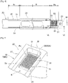
Fig. 1 is a schematic view showing a configuration of a component mounting machine. -
Fig. 2 is a perspective view showing an appearance of a bulk feeder. -
Fig. 3 is a side view schematically showing a main part of the bulk feeder. -
Fig. 4 is a plan view seen from a IV direction ofFig. 3 . -
Fig. 5 is a perspective view showing a first aspect of an alignment member in a supply region. -
Fig. 6 is an enlarged schematic view showing a cross section of VI-VI ofFig. 4 . -
Fig. 7 is a schematic view corresponding toFig. 6 , which shows a second aspect of the alignment member in the supply region. -
Fig. 8 is a plan view corresponding toFig. 4 , which shows a third aspect of the alignment member in the supply region. -
Fig. 9 is a plan view corresponding toFig. 4 , which shows a fourth aspect of the alignment member in the supply region in an enlarged manner. -
Fig. 10 is a conceptual view showing a configuration in which a track member or the alignment member can be selectively attached to the bulk feeder. -
Fig. 11 is a flowchart showing a mounting process by the component mounting machine. -
Fig. 12 is a view showing image data used for recognition processing of a supply state of components in the supply region. -
Fig. 13 is a view showing an aspect in which multiple suction nozzles execute a collection operation of the components at the same time in a modification aspect of the embodiment. -
Component mounting machine 10 configures a production line for producing a board product together with multiple types of board work machines including, for example, anothercomponent mounting machine 10. The board work machine configuring the production line described above can include a printer, an inspection device, a reflow furnace, or the like. - As shown in
Fig. 1 ,component mounting machine 10 includesboard conveyance device 11.Board conveyance device 11 sequentially conveysboard 91 in a conveyance direction, andpositions board 91 at a predetermined position in the machine. -
Component mounting machine 10 includescomponent supply device 12.Component supply device 12 supplies components to be mounted onboard 91.Component supply device 12 is equipped withfeeder 122 in each ofmultiple slots 121. Feeder 122 includes a tape feeder that supplies the components to be collectable, for example, by feeding and moving a carrier tape accommodating a large number of components. In addition,feeder 122 includesbulk feeder 20 that supplies the components accommodated in a bulk state (in a loose state in which each posture is irregular) to be collectable. Details ofbulk feeder 20 will be described below. -
Component mounting machine 10 includescomponent transfer device 13.Component transfer device 13 transfers the components supplied bycomponent supply device 12 to a predetermined mounting position onboard 91.Component transfer device 13 includeshead driving device 131, moving table 132,mounting head 133, andsuction nozzle 134.Head driving device 131 moves moving table 132 in a horizontal direction (X-direction and Y-direction) by a linear motion mechanism.Mounting head 133 is detachably fixed to moving table 132 by a clamp member (not shown), and is provided to be movable in the horizontal direction in the machine. - Mounting
head 133 supportsmultiple suction nozzles 134 to be able to be rotated and raised and lowered.Suction nozzle 134 is a holding member that collects and holdscomponent 92 supplied byfeeder 122.Suction nozzle 134 picks up the components supplied byfeeder 122 by supplied negative pressure air. As the holding member attached to mountinghead 133, a chuck or the like that holds the components by gripping the components can be adopted. - Here, as mounting
head 133 described above, various types can be adopted. Specifically, as mountinghead 133, there is a type in which multiple holding members are supported by a rotary head provided to be rotatable around an R-axis parallel to a vertical axis (Z-axis). In the present embodiment, mountinghead 133 supports 24suction nozzles 134 by the rotary head. In addition, as mountinghead 133, there are a type in which the multiple holding members arranged linearly or in a matrix are supported, a type in which one holding member is supported, and the like. The type of mountinghead 133 can be appropriately selected in accordance with, for example, a type of board product to be produced. -
Component mounting machine 10 includespart camera 14 andboard camera 15.Part camera 14 andboard camera 15 are digital imaging devices having imaging elements, such as a CMOS.Part camera 14 andboard camera 15 execute imaging based on control signals and send image data acquired by the imaging.Part camera 14 is configured to image the components held bysuction nozzle 134 from below.Board camera 15 is provided on moving table 132 to be movable in the horizontal direction integrally with mountinghead 133.Board camera 15 is configured to imageboard 91 from above. - In addition to using a surface of
board 91 as an imaging target,board camera 15 can use various devices and the like as the imaging target as long as various devices are within a movable range of moving table 132. For example, in the present embodiment,board camera 15 can image supply region As (seeFig. 4 ) to whichbulk feeder 20supplies components 92. As described above,board camera 15 can be used for imaging different imaging targets to acquire the image data used for various pieces of image processing. -
Component mounting machine 10 includescontrol device 16.Control device 16 is mainly composed of CPU, various memories, or a control circuit.Control device 16 includes a storage device (not shown). The storage device is composed of an optical drive device, such as a hard disk device or a flash memory. The storage device ofcontrol device 16 stores various data, such as a control program used for controlling a mounting process. The control program indicates the mounting position and a mounting order of the components mounted onboard 91 in the mounting process. -
Control device 16 executes recognition processing of a holding state of the component held by each of multiple holding members (suction nozzles 134). Specifically,control device 16 executes the image processing on the image data acquired by the imaging ofpart camera 14 and recognizes a position and an angle of each component with respect to a reference position of mountinghead 133. It should be noted that, in addition topart camera 14,control device 16 may execute the image processing on the image data acquired by imaging the components by a head camera unit or the like provided integrally with mountinghead 133 from side, below, or above. -
Control device 16 controls a mounting operation of the components by mountinghead 133 based on the control program to execute the mounting process. Here, the mounting process includes a process of repeating a pick-and-place cycle (hereinafter, referred to as "PP cycle") including a collection operation and the mounting operation multiple times. The "collection operation" described above is an operation of collecting the components supplied bycomponent supply device 12 bysuction nozzle 134. - In the present embodiment, in a case where the collection operation described above is executed,
control device 16 controls the operation ofcomponent supply device 12 includingbulk feeder 20 and executes recognition processing of a supply state ofcomponents 92 in supply region As ofbulk feeder 20. The "recognition processing of the supply state" described above includes processing of recognizing whethercomponents 92 that can be collected are present in supply region As, and recognizing the positions ofcomponents 92 in a case wherecomponents 92 are present, as needed. Moreover,control device 16 controls an operation of mountinghead 133 in the collection operation based on a result of the recognition processing of the supply state. - In addition, the "mounting operation" described above is an operation of mounting the collected components at the predetermined mounting position on
board 91. In the mounting process,control device 16 controls the operation of mountinghead 133 based on information output from various sensors, the result of image processing, a control program, or the like. As a result, the positions and the angles ofmultiple suction nozzles 134 supported by mountinghead 133 are controlled. -
Bulk feeder 20 is mounted oncomponent mounting machine 10 and functions as at least a part ofcomponent supply device 12. Since, unlike the tape feeder,bulk feeder 20 does not use the carrier tape, there is an advantage in that loading of the carrier tape, collection of used tape, or the like can be omitted. On the other hand, sincebulk feeder 20supplies components 92 accommodated in the bulk state which are not aligned like the carrier tape, the supply state ofcomponents 92 can affect the collection operation by the holding member, such assuction nozzle 134. - Specifically, in a case where
components 92 are close enough to be in contact with each other or are deposited (state of overlapping in the up-down direction) in supply region As,components 92 cannot be used as a collection target. In addition, in a case wherecomponents 92 are supplied to supply region As in an irregular posture, the image processing of recognizing the supply state (whethercomponents 92 can be collected and posture ofcomponents 92 that can be collected) is required. Therefore, it is desired thatbulk feeder 20 be in a state of being supplied withmultiple components 92 that can be collected in supply region As without being insufficient in the required number, and is further appropriately dispersed. - On the other hand, it is assumed that
bulk feeder 20 adopts a configuration in whichmultiple components 92 are aligned in a row by, for example, an alignment mechanism provided on a conveyance path beforecomponents 92 reach supply region As. However, in the configuration described above, it is necessary to provide the alignment mechanism on the conveyance path, and it is further necessary to maintain an aligned state and conveycomponents 92 to supply region As. Therefore,bulk feeder 20 of the present embodiment adopts a configuration in whichcomponents 92 are conveyed by using vibration andcomponents 92 are aligned by using the vibration in supply region As. - As shown in
Fig. 2 ,bulk feeder 20 includes feedermain body 21. Feedermain body 21 is formed in a flat box shape. Feedermain body 21 is set inslot 121 ofcomponent supply device 12.Connector 211 and twopins 212 are formed on a front part of feedermain body 21. In a case wherebulk feeder 20 is set inslot 121,connector 211 is communicably connected to a main body side ofcomponent mounting machine 10. In addition,bulk feeder 20 is supplied with power viaconnector 211. Twopins 212 are used for positioning in a case where feedermain body 21 is set inslot 121. - In the present embodiment,
component case 22 accommodatingmultiple components 92 in the bulk state is detachably attached to feedermain body 21.Component case 22 is configured to dischargecomponents 92 to the outside. In the present embodiment,component case 22 is an external device ofbulk feeder 20, for example, one of various types suitable for the mounting process is selected and attached to feedermain body 21. -
Bulk feeder 20 includesdischarge device 23.Discharge device 23 adjusts the number ofcomponents 92 discharged fromcomponent case 22.Discharge device 23 suppliesmultiple components 92 discharged fromcomponent case 22 to reception region Ar oftrack member 30, which will be described below.Bulk feeder 20 includescover 24.Cover 24 is detachably attached to a front upper part of feedermain body 21.Cover 24 preventscomponents 92 conveyed along conveyance path R oftrack member 30, which will be described below, from scattering to the outside. -
Bulk feeder 20 includestrack member 30.Track member 30 is provided on the front upper part of feedermain body 21. As shown inFigs. 3 and4 ,track member 30 is formed to extend in a front-rear direction (right-left direction ofFigs. 3 and4 ) of feedermain body 21. Pair ofside walls 31 protruding upward are formed on both edges oftrack member 30 in the width direction (up-down direction inFig. 4 ). Pair ofside walls 31 surround the peripheral edge of conveyance path R together withdistal end portion 32 oftrack member 30 to prevent leakage ofcomponents 92 conveyed along conveyance path R.Circular reference mark 33 indicating the reference position ofbulk feeder 20 is attached to an upper face ofdistal end portion 32. -
Track member 30 having the configuration described above has reception region Ar, supply region As, and conveyance path R. Here, "reception region Ar" is a region in whichcomponents 92 in the bulk state, which are discharged fromcomponent case 22, are received. Reception region Ar of the present embodiment is positioned below a discharge port ofcomponent case 22. In addition, "supply region As" is a region to whichcomponents 92 are supplied. In other words, "supply region As" is a region in whichcomponents 92 can be collected bysuction nozzle 134 supported by mountinghead 133, and is included in the movable range of mountinghead 133. - In addition, "conveyance path R" of
track member 30 is a path ofcomponents 92 from reception region Ar to supply region As. In the present embodiment, conveyance path R is formed in a groove shape in which a groove bottom face is horizontal. A groove side face of conveyance path R is formed by pair ofside walls 31. A groove opening on an upper side of conveyance path R is largely closed bycover 24.Track member 30 is supported to be slightly displaceable (that is, can vibrate) with respect to feedermain body 21 in a virtual vertical plane formed in the front-rear direction and the up-down direction. -
Bulk feeder 20 includesvibration device 40.Vibration device 40 is provided on feedermain body 21.Vibration device 40 applies the vibration to trackmember 30 such thatcomponents 92 on conveyance path R are conveyed. Specifically,vibration device 40 includes multiplefirst support sections 41, multiple firstpiezoelectric elements 42, multiplesecond support sections 43, multiple secondpiezoelectric elements 44, and drivingsection 45.First support section 41 andsecond support section 43 are connecting members that connect feedermain body 21 andtrack member 30. -
First support section 41 is formed in a shape that is inclined and extends forward with respect to the vertical direction.Second support section 43 is formed in a shape that is inclined and extends rearward with respect to the vertical direction. Firstpiezoelectric element 42 and secondpiezoelectric element 44 vibrate at a frequency corresponding to the power supplied from drivingsection 45. Firstpiezoelectric element 42 is attached tofirst support section 41. Secondpiezoelectric element 44 is attached tosecond support section 43. In a case where firstpiezoelectric element 42 vibrates, the vibration is applied to trackmember 30 viafirst support section 41. Similarly, in a case where secondpiezoelectric element 44 vibrates, the vibration is applied to trackmember 30 viasecond support section 43. - In addition, amplitude of
track member 30 is changed in accordance with the voltage applied to firstpiezoelectric element 42 or secondpiezoelectric element 44.Vibration device 40 applies the vibration to trackmember 30 by causing firstpiezoelectric element 42 attached tofirst support section 41 that is inclined forward to vibrate. As a result,vibration device 40 causestrack member 30 to execute clockwise elliptical movement in the horizontal direction (the front-rear direction inFig. 3 ) orthogonal to the conveyance direction ofcomponents 92 in conveyance path R. In this case,vibration device 40 causestrack member 30 to vibrate such that external force directed forward and upward is applied tocomponents 92 on conveyance path R. - In addition,
vibration device 40 applies the vibration to trackmember 30 by causing secondpiezoelectric element 44 attached tosecond support section 43 that is inclined rearward to vibrate. As a result,vibration device 40 causestrack member 30 to execute counterclockwise elliptical movement in the horizontal direction (the front-rear direction inFig. 3 ) orthogonal to the conveyance direction ofcomponents 92 in conveyance path R. In this case,vibration device 40 causestrack member 30 to vibrate such that external force directed rearward and upward is applied tocomponents 92 on conveyance path R. - Driving
section 45 changes the frequency of the power supplied to firstpiezoelectric element 42 and secondpiezoelectric element 44 and the applied voltage based on a command offeeder control device 70, which will be described below. As a result, the frequency and the amplitude of the vibration applied to trackmember 30 are adjusted, and a rotation direction of the elliptical movement oftrack member 30 is determined. In a case where the frequency or the amplitude of the vibration oftrack member 30 and the rotation direction of the elliptical movement due to the vibration are changed, a conveyance speed ofcomponents 92 to be conveyed, a degree of dispersion ofcomponents 92, the conveyance direction, and the like are changed. - With the configuration described above,
vibration device 40 applies predetermined vibration to trackmember 30, andmultiple components 92 discharged fromcomponent case 22 to reception region Ar oftrack member 30 can be conveyed to supply region As via conveyance path R. In the following, an operation ofvibration device 40 of conveyingcomponents 92 on conveyance path R in a direction toward supply region As is referred to as a "feeding operation". In addition, an operation ofvibration device 40 of conveyingcomponents 92 on conveyance path R in a direction toward reception region Ar is referred to as a "returning operation". It should be noted that the elliptical movement of track member becomes reverse rotation by switching between the feeding operation and the returning operation ofvibration device 40. -
Bulk feeder 20 includesalignment member 50.Alignment member 50 is provided in supply region As oftrack member 30.Alignment member 50 guidesmultiple components 92 conveyed by the vibration oftrack member 30 and alignsmultiple components 92 with respect to feedermain body 21. Foralignment member 50 that alignscomponents 92, for example, the following first to fourth aspects can be adopted. - As shown in
Fig. 5 ,alignment member 50A of a first aspect hasmultiple cavities 51 that individually accommodatemultiple components 92. Specifically,multiple cavities 51 are arranged in a matrix in supply region As. For example,alignment member 50A has 120cavities 51 in total in which 10 cavities are regularly arranged in the conveyance direction and 12 cavities are regularly arranged in the width direction of conveyance path R. - In addition, as shown in
Fig. 6 , each ofmultiple cavities 51 is open on an upper face of conveyance path R, and accommodatescomponent 92 in a posture in which a thickness direction ofcomponent 92 is the up-down direction. The opening ofcavity 51 is set to a size slightly larger than an outer shape ofcomponent 92 in an upward view. Depth Dc ofcavity 51 can be appropriately set in accordance with the type (shape, mass, or the like) ofcomponent 92. In a state in which depth Dc ofcavity 51 is set shallow andcomponent 92 protrudes from the upper face of conveyance path R, interference betweensuction nozzle 134 andalignment member 50A in the collection operation can be reliably prevented. - On the other hand, in a state in which depth Dc of
cavity 51 is set deep andcomponent 92 is lower than the upper face of conveyance path R, coming out ofcomponent 92 once accommodated incavity 51 again is reduced. Therefore, depth Dc of each ofmultiple cavities 51 inalignment member 50A of the first aspect is set to be equal to or larger than thickness Tp ofcomponent 92. It should be noted that, in a case where depth Dc ofcavity 51 is too deep, there is a risk that anothercomponent 92 is prevented from moving in the conveyance direction on the upper side ofcavity 51 in a state of accommodatingcomponent 92. - Therefore, it is preferable that depth Dc of
cavity 51 be set such that an upper end ofcomponent 92 accommodated incavity 51 is slightly lower than the upper face of conveyance path R. As described above, the shape (opening, depth, or the like) ofcavity 51 is appropriately set. In a case where it is assumed thatcomponents 92 are accommodated in the carrier tape and supplied by the tape feeder, the shape ofcavity 51 ofalignment member 50A of the first aspect is similar to the shape of the cavity formed in the carrier tape. -
Alignment member 50B of a second aspect has a different storage direction ofcomponents 92 from the first aspect. Specifically, as shown inFig. 7 , each ofmultiple cavities 51 is open on an upper face of conveyance path R, and accommodatescomponent 92 in a posture in which a longitudinal direction ofcomponent 92 is the up-down direction. With such a configuration,components 92 can be supplied in the posture described above. In addition, since the opening size ofcavity 51 can be reduced, it is possible to arrange a relatively large number ofcavities 51 in limited supply region As. - Depth Dc of
cavity 51 ofalignment member 50B of the second aspect can be appropriately set. For example, the depth ofcavity 51 is set to be slightly larger than length Lp in the longitudinal direction ofcomponent 92, and the upper end of accommodatedcomponent 92 is set to be lower than the upper face of conveyance path R. In addition, in the aspect in whichcomponent 92 is accommodated in such a posture, sincecomponent 92 once accommodated is relatively stable, depth Dc ofcavity 51 may be set such that the upper end ofcomponent 92 is higher than the upper face of conveyance path R. -
Alignment member 50C of a third aspect has a different shape and number ofcavities 51 from the first aspect. Specifically,alignment member 50C has 48cavities 51 in total in which 6 cavities are regularly arranged in the conveyance direction and 8 cavities are regularly arranged in the width direction of conveyance pathR. Alignment member 50C of the third aspect hascavities 51 having the shape and number described above in order to correspond tocomponents 92 supplied bybulk feeder 20 having a larger size than the first aspect. - It should be noted that, as shown in the first aspect and the third aspect, the shape of
cavity 51 is appropriately set in accordance with the shape ofcomponent 92 and the accommodating posture. Moreover, in a case where the shape ofcavity 51 is set, the occupied area of onecavity 51 in supply region As is determined. Further, the number ofcavities 51 inalignment member 50 is appropriately set in consideration of the shape, the required number, and the degree of density of thecavities 51, which can affect the conveyance property. - The number of
cavities 51 inalignment members 50A to 50C of the first to third aspects is set to be larger than the maximum number ofcomponents 92 collected by the collection operation in one PP cycle. It should be noted that the "maximum number" described above corresponds to the number ofsuction nozzles 134 supported by mountinghead 133. In the present embodiment, since mountinghead 133 supports 24suction nozzles 134, the number ofcavities 51 is set to be more than at least 24. - In addition,
alignment member 50 including the first to third aspects may be configured to have a magnet (not shown) acting oncomponent 92 positioned on the upper part orcomponent 92 accommodated incavity 51. Specifically, the magnet is embedded in a portion deeper than the bottom ofcavity 51. In a case where magnetic force of the magnet is large enough to act on the upper part ofalignment member 50, the magnet guidescomponent 92 intocavity 51 by the magnetic force. As a result,components 92 are efficiently accommodated inmultiple cavities 51. - In addition, in a case where the magnetic force of the magnet does not act on the upper part of
alignment member 50 but acts oncomponent 92 accommodated incavity 51, the magnet holdscomponent 92 accommodated incavity 51 by the magnetic force. As a result, it is possible to preventcomponent 92 once accommodated from coming out. It should be noted that the magnet described above may be a permanent magnet or an electromagnet. In addition, the magnet may be a magnetized material disposed at the bottoms ofmultiple cavities 51. Further, the magnets may be disposed for each ofmultiple cavities 51, or may be disposed to act on a part or all ofmultiple cavities 51. -
Alignment member 50D of a fourth aspect hasmultiple alignment grooves 55 andmultiple guide portions 56 in place ofcavities 51. As shown inFig. 9 , each ofmultiple alignment grooves 55 is formed to extend in the conveyance direction. A groove width ofalignment groove 55 is formed to be slightly wider than width Wp ofcomponent 92 and shorter than length Lp ofcomponent 92. - Each of
multiple guide portions 56 communicates with a rear side ofalignment groove 55 in the conveyance direction, and is formed in a funnel shape in which the opening width is increased toward the rear side in the conveyance direction. With such a configuration ofalignment member 50D of the fourth aspect,components 92 conveyed by the feeding operation are guided toalignment grooves 55 ascomponents 92 are conveyed to the front side in the conveyance direction. In a case wherecomponents 92 are further conveyed to the front side in the conveyance direction,components 92 are aligned such that the longitudinal direction faces the conveyance direction. -
Multiple components 92 are sequentially conveyed in a state of being accommodated inalignment grooves 55 untilmultiple components 92 reach a front end ofalignment grooves 55. With such a configuration, multiple alignedcomponents 92 can be sequentially supplied alongalignment grooves 55. In addition,alignment member 50D may further have a regulating member that regulates the conveyance ofcomponent 92 on the upper side in a case wherecomponents 92 are deposited on each other. As a result,multiple components 92 can be aligned. -
Bulk feeder 20 includesfeeder control device 70.Feeder control device 70 is mainly composed of CPU, various memories, or a control circuit.Feeder control device 70 is supplied with the power viaconnector 211, and is capable of communicating withcontrol device 16 ofcomponent mounting machine 10 in a state in whichbulk feeder 20 is set inslot 121. - As shown in
Fig. 3 ,feeder control device 70 includesstorage section 71.Storage section 71 is composed of a flash memory or the like.Storage section 71 stores various data, such as a program used for controlling the component supplying process or conveyance parameter F1. "Conveyance parameter F1" described above is a parameter for controlling the operation ofvibration device 40 such that the vibration applied to trackmember 30 is appropriate in a case wherecomponents 92 are conveyed in the component supplying process, and is set in advance in association with the types ofcomponents 92, for example. -
Feeder control device 70 includesconveyance control section 72.Conveyance control section 72 controls the operation ofvibration device 40 and executes the feeding operation and the returning operation described above. Specifically,conveyance control section 72 sends a command to drivingsection 45 ofvibration device 40 in a case of executing the feeding operation. As a result, by drivingsection 45 supplying predetermined power to firstpiezoelectric element 42, the vibration is applied to trackmember 30 viafirst support section 41. As a result,components 92 on conveyance path R are conveyed by receiving the external force to move to the front side in the conveyance direction. - In addition,
conveyance control section 72 realizes various conveyance aspects by combining the execution time of the feeding operation and the returning operation ofvibration device 40, or the like. For example, in a case wherealignment member 50 hasmultiple cavities 51,conveyance control section 72 may execute an accommodation step and a retraction step as described below. The "accommodation step" described above is a step of accommodatingcomponents 92 in at least a part ofmultiple cavities 51 by executing the feeding operation until at least a part ofmultiple components 92 on conveyance path R reaches supply region As. - In this case,
conveyance control section 72 may repeatedly execute the feeding operation and the returning operation and may retainmultiple components 92 in supply region As in a state in whichtrack member 30 vibrates after at least a part ofmultiple components 92 on conveyance path R reaches the supply region As, in the accommodation step. In addition, the "retraction step" described above is a step of retracting remainingcomponents 92 from supply region As toward reception region Ar by executing the returning operation in a state in which at least a part ofmultiple components 92 on conveyance path R is accommodated inmultiple cavities 51, after executing the accommodation step. -
Conveyance control section 72 can appropriately set the execution time of the feeding operation or the returning operation in each step, the time of the retention operation in the accommodation step, and the number of executions of the repetitive operation. In addition, in accordance with the number of remainingcomponents 92 on conveyance path R, the retention operation in the accommodation step or the retraction step may be omitted. Further,conveyance control section 72 may adjust at least one of the frequency and the amplitude of the vibration applied to trackmember 30 byvibration device 40 in accordance with the type ofcomponents 92 accommodated incomponent case 22. - Specifically, in a case where
component case 22 is attached tobulk feeder 20, the types ofcomponents 92 replenished incomponent case 22 and identification information ofbulk feeder 20 are verified. Moreover, in a case wherebulk feeder 20 is set inslot 121,conveyance control section 72 acquires parameters in accordance with the types ofcomponents 92 from conveyance parameter F1. As a result,conveyance control section 72 adjusts the command to be sent to drivingsection 45 ofvibration device 40. - As a result, the frequency or the like of the vibration applied to track
member 30 byvibration device 40 is adjusted in accordance with the types of the components. A configuration may be adopted in which conveyance parameter F1 described above is appropriately switched in accordance with various aspects adopted foralignment member 50 in addition to the types ofcomponents 92. As a result, the accommodation step, the retention operation, or the retraction step is suitably executed. Further, conveyance parameter F1 may be updated by an administrator based on the result (including the success rate or the like) of the component supplying process executed in the past. - Here, a configuration may be adopted in which
alignment member 50 ofbulk feeder 20 is attached to trackmember 30 to be exchangeable. Specifically, in a case of setting upbulk feeder 20, as shown inFig. 10 , for example, multiple types ofalignment members 50A to 50D corresponding to the first to fourth aspects are prepared to be exchangeable. Moreover, inbulk feeder 20, one selected from multiple types ofalignment members 50A to 50D having different shapes from each other corresponding to the types ofcomponents 92 to be supplied is attached to trackmember 30. - With such a configuration,
bulk feeder 20 can share feedermain body 21,track member 30, orvibration device 40, and can handle the types or the supply aspects ofcomponents 92 by exchangingalignment member 50. As a result, a range of use ofbulk feeder 20 can be enlarged, and a production cost of the board product can be reduced. - Further, a configuration may be adopted
track member 30 ofbulk feeder 20 is attached to feedermain body 21 to be exchangeable. In this case,alignment member 50 may be formed integrally withtrack member 30, or may be exchangeable. Specifically, in a case of setting upbulk feeder 20, as shown inFig. 10 , for example, multiple types oftrack members 30A to 30D on which multiple types ofalignment members 50A to 50D corresponding to the first to fourth aspects are formed are prepared to be exchangeable. - Moreover, in
bulk feeder 20, one selected from multiple types oftrack members 30A to 30D on which one of multiple types ofalignment members 50A to 50D having different shapes corresponding to the type ofcomponents 92 to be supplied is formed is attached to feedermain body 21. With such a configuration,bulk feeder 20 can share feedermain body 21 orvibration device 40, and can handle the types or the supply aspects ofcomponents 92 by exchangingtrack member 30. As a result, a range of use ofbulk feeder 20 can be enlarged, and a production cost of the board product can be reduced. - The mounting process by
component mounting machine 10 will be described with reference toFigs. 11 and12 . Here, a configuration is adopted in whichbulk feeder 20 includesalignment member 50 in whichmultiple cavities 51 are formed in a matrix. In addition, afterbulk feeder 20 described above is set inslot 121,control device 16 executes calibration processing and recognizes the position ofalignment member 50 in the machine. - In the calibration processing described above,
control device 16 firstmoves board camera 15 abovereference mark 33 ofbulk feeder 20 and acquires the image data by the imaging ofboard camera 15. Moreover,control device 16 recognizes the position ofalignment member 50 in the machine based on the position ofreference mark 33 included in the image data by the image processing and the position ofboard camera 15 when the image is captured. - In addition,
control device 16 includes arrangement information indicating the shape ofalignment member 50 included inbulk feeder 20, that is, a positional relationship ofmultiple cavities 51.Control device 16 may acquire the arrangement information described above fromfeeder control device 70 ofbulk feeder 20, or may acquire the arrangement information from a host device or the like in accordance with the type ofalignment member 50 identified based on the image data acquired byimaging reference mark 33.Control device 16 recognizes the position ofalignment member 50, specifically the position ofindividual cavity 51, by the calibration processing. - In the mounting process, first,
board conveyance device 11 ofcomponent mounting machine 10 executes convey-in processing of board 91 (S11). As a result,board 91 is conveyed in the machine and is positioned at a predetermined position in the machine.Control device 16 executes a first component supplying process bybulk feeder 20 after S11 or in parallel with S11. Specifically, first,control device 16 causesbulk feeder 20 to execute alignment processing of aligningcomponents 92 in supply region As (S21). As a result,conveyance control section 72 ofbulk feeder 20 executes the accommodation step or the retraction step described above. - Next,
control device 16 executes the recognition processing the supply state ofcomponents 92 in supply region As (S22). Specifically,control device 16 firstmoves board camera 15 abovealignment member 50 in supply region As ofbulk feeder 20, and acquires image data M by the imaging ofboard camera 15. Moreover, as shown inFig. 12 ,control device 16 executes predetermined image processing on image data M and recognizescomponents 92 accommodated inmultiple cavities 51, respectively. - Specifically,
control device 16 determines whethercomponents 92 can be collected based on the positions ofmultiple cavities 51 recognized by the calibration processing and the posture ofcomponents 92 in image data M subjected to the image processing. Specifically,control device 16 determines thatcomponents 92 appropriately accommodated incavities 51 can be collected ("OK" inFig. 12 ).Control device 16 determines thatcomponents 92 accommodated in an inappropriate posture, such as a tilted posture, incavities 51 ormultiple components 92 in a state of being deposited on each other cannot be collected ("NG" inFig. 12 ). - As described above, in the recognition processing of the supply state (S22),
control device 16 recognizes the supply state indicating whethercomponents 92 are accommodated inmultiple cavities 51 to be collectable by the image processing on image data M. It should be noted that, in addition to this,control device 16 may recognize the positions ofcomponents 92 by usingcomponents 92 that can be collected as targets. That is,control device 16 calculates a coordinate value of the reference position. - The "reference position" described above of the components that can be collected is a position optionally set on the upper face of
component 92, and is set to, for example, a center, a centroid, or a flat region ofcomponent 92 suitable for pick-up bysuction nozzle 134 in a case wheresuction nozzle 134 is used for the collection operation. In the image processing,control device 16 calculates the coordinate value of the reference position in the component that can be collected by recognizing, for example, the outer shape, or the center position of the component that can be collected. - Subsequently, in a case where the number (supply number) of
components 92 that can be collected is less than the number ofcomponents 92, which is scheduled to be collected in the current PP cycle, in the result of the recognition processing (S22) of the supply state (S23: No),control device 16cause bulk feeder 20 to execute the alignment processing (S21) again. For example, in a case wherecomponents 92 supplied bybulk feeder 20 are collected by 20suction nozzles 134 among 24suction nozzles 134 in the collection operation of the current PP cycle, the number (required number) ofcomponents 92, which is scheduled to be collected, is 20. - As described above, in a case where the required number of
components 92 cannot be collected in the current PP cycle in the current supply state ofcomponents 92 in supply region As,control device 16 repeatedly executes the alignment processing (S21) and the recognition processing of the supply state (S22). It should be noted that in a case where the required number is large, the current supply number ofcomponents 92 may be first collected out of the required number thereof, and then the alignment processing (S21) and the recognition processing of the supply state (S22) may be executed to try the collection again. - On the other hand, in a case where the current supply number is equal to or larger than the required number in the current PP cycle (S23: Yes),
control device 16 executes the PP cycle. In the PP cycle,control device 16 repeatedly executes the collection operation of collecting the components using multiple suction nozzles 134 (S12). In this case,control device 16 controls the operation of mountinghead 133 in the collection operation to sequentiallyposition mounting head 133 in accordance with the positions ofcomponents 92 that can be collected based on the result of the recognition processing of the supply state (S22). - Here, it is assumed that the result of the recognition processing of the supply state (S22) indicates whether
component 92 that can be collected is present for each ofmultiple cavities 51. In this case, in the collection operation,control device 16 controls the operation of mountinghead 133 to positionsuction nozzle 134 at the center ofcavity 51 that accommodatescomponent 92 to be collectable. In addition, in a case where the result of the recognition processing of the supply state (S22) includes the coordinate value of the reference position in the component that can be collected,control device 16 may control the operation of mountinghead 133 to positionsuction nozzle 134 to the coordinate value of the reference position described above, not the center ofcavity 51. - Subsequently,
control device 16 executes the recognition processing of the holding state ofcomponents 92 held by multiple suction nozzles 134 (S13). Specifically,control device 16moves mounting head 133 abovepart camera 14 and sends an imaging command topart camera 14.Control device 16 executes the image processing on the image data acquired by the imaging ofpart camera 14 to recognize the posture (position and angle) ofcomponent 92 held by each ofmultiple suction nozzles 134. - Thereafter,
control device 16 repeatedly executes the mounting operation of mounting the components using multiple suction nozzles 134 (S14). It should be noted that in mounting operation (S14),control device 16 controls the operation of mountinghead 133 to mountcomponents 92 at the mounting positions designated by the control program. Further, mountinghead 133 controls the operation of mountinghead 133 such thatsuction nozzle 134 is positioned and angled with respect to the mounting position based on the result of the recognition processing (S13). - In addition,
control device 16 causesbulk feeder 20 to execute the alignment processing of aligningcomponents 92 in supply region As in a period from termination of the collection operation (S12) of the current PP cycle described above to start of the collection operation (S12) of the next PP cycle (second component supplying process). Specifically, after the collection operation (S12) of the current PP cycle is terminated, in a case where the current supply number is less than the required number in next PP cycle (S31: No),control device 16 causesbulk feeder 20 execute the preceding alignment processing (S32). Since this preceding alignment processing (S32) is the same as the alignment processing (S21), the detailed description thereof will be omitted. - On the other hand, in a case where the current supply number is equal to or larger than the required number in the next PP cycle (S31: Yes) or after the alignment processing (S32) is executed,
control device 16 terminates the second component supplying process executed in parallel with the current PP cycle.Control device 16 determines whether all the PP cycles are terminated based on the control program (S15). In a case where all the PP cycles are not terminated (S15: No),control device 16 determines whether the preceding alignment processing (S32) is executed during the execution of the immediately preceding PP cycle (S16). - In a case where the preceding alignment processing (S32) is executed (S16: Yes), since the current state of supply region As is unknown,
control device 16 executes the recognition processing of the supply state (S22) in the first component supplying process again, and then executes the next PP cycle (S12 to S14). On the other hand, in a case where the preceding alignment processing (S32) is not executed (S16: No), the first component supplying process is omitted and the next PP cycle (S12 to S14) is executed. - As described above, in accordance with the number of
cavities 51, the number (supply number) ofcomponents 92 that can be collected in the result of the recognition processing of the supply state (S22) in the first component supplying process may be equal to or larger than the sum of the number ofcomponents 92 which is scheduled to be collected in the current PP cycle and in the next PP cycle. In such a case,control device 16 omits the execution of the alignment processing (S21) for the next PP cycle scheduled after the collection operation of the current PP cycle is terminated. Further,control device 16 controls the operation of mountinghead 133 of the collection operation (S12) of the next PP cycle based on the result of the recognition processing of the supply state (S22) executed previously. - In a case where all the PP cycles are terminated (S15: Yes),
control device 16 executes convey-out processing of board 91 (S17). In the convey-out processing ofboard 91,board conveyance device 11 unclamps positionedboard 91 and conveyedboard 91 out of the outside ofcomponent mounting machine 10. - With such a configuration,
bulk feeder 20 alignsmultiple components 92 in supply region As by usingalignment member 50. As a result, it is possible to efficiently supplycomponents 92 in supply region As without enlarging supply region As to secure the supply number ofcomponents 92 that can be collected. As a result, it is possible to suitably supplymultiple components 92 to be collectable while reducing the size ofbulk feeder 20 in the width direction. In addition, since the components are aligned in supply region As, the load of the recognition processing of the supply state (S22) ofcomponents 92 in supply region As can be reduced as compared with the configuration in which the components are supplied in the bulk state. - In the embodiment, mounting
head 133 is configured to include the rotary head that supportsmultiple suction nozzles 134 to be able to be raised and lowered. On the other hand, as shown inFig. 13 , mountinghead 133 may support twosuction nozzles 134 to be able to be raised and lowered independently and at a predetermined interval (nozzle pitch Pn). In addition,alignment member 50 ofbulk feeder 20 alignsmultiple components 92 at defined interval Ps in supply region As. - In the configuration described above, mounting
head 133 supports twosuction nozzles 134 such that nozzle pitch Pn is an interval of an integral multiple (N) of defined interval Ps. Moreover, in the collection operation (S12),control device 16 collects twocomponents 92 by operating mountinghead 133 such that at least parts of raising and lowering of twosuction nozzles 134 overlap in a state of maintaining a position of mountinghead 133 in the horizontal direction. - With such a configuration, since
component mounting machine 10 can simultaneously execute, for example, the raising and lowering operation ofmultiple suction nozzles 134 in the collection operation of the PP cycle, the required time for the collection operation can be shortened. In addition, in the configuration in which mountinghead 133 is provided with the rotary head, in a case of a configuration in which multiple raising and lowering devices that raise and lower twosuction nozzles 134 are provided, the same collection operation as described above can be executed. - 10: component mounting machine, 12: component supply device, 13: component transfer device, 133: mounting head, 134: suction nozzle (holding member), 14: part camera, 15: board camera, 16: control device, 20: bulk feeder, 21: feeder main body, 22: component case, 30, 30A to 30D: track member, 40: vibration device, 50, 50A to 50D: alignment member, 51: cavity, 55: alignment groove, 56: guide portion, 70: feeder control device, 72: conveyance control section, 91: board, 92: component, Ar: reception region, As: supply region, R: conveyance path, Dc: depth (of cavity), Ps: defined interval (of cavity), Pn: nozzle pitch (interval of suction nozzle (holding member)), F1: conveyance parameter, M: image data, Tp: thickness (of component), Wp: width (of component), Lp: length (of component)
Claims (18)
- A bulk feeder comprising:a feeder main body;a track member provided in the feeder main body and having a reception region in which multiple components discharged from a component case accommodating the components in a bulk state are received, a supply region to which the components are supplied, and a conveyance path of the components from the reception region to the supply region;a vibration device provided in the feeder main body and configured to apply vibration to the track member such that the components on the conveyance path are conveyed; andan alignment member provided in the supply region of the track member and configured to align the multiple components conveyed by the vibration of the track member with respect to the feeder main body.
- The bulk feeder according to claim 1,
wherein the alignment member has multiple cavities individually accommodating the multiple components. - The bulk feeder according to claim 2,
wherein the multiple cavities are arranged in a matrix in the supply region. - The bulk feeder according to any one of claims 2 or 3,
wherein each of the multiple cavities is open on an upper face of the conveyance path and accommodates the component in a posture in which a thickness direction of the component is in an up-down direction. - The bulk feeder according to claim 4,
wherein a depth of each of the multiple cavities is set to be equal to or larger than a thickness of the component. - The bulk feeder according to any one of claims 2 or 3,
wherein each of the multiple cavities is open on an upper face of the conveyance path and accommodates the component in a posture in which a longitudinal direction of the component is in an up-down direction. - The bulk feeder according to any one of claims 2 to 6,wherein the bulk feeder is mounted on a component mounting machine and functions as at least a part of a component supply device,the component mounting machine is configured to repeatedly execute a PP cycle including a collection operation of collecting the multiple components from the component supply device and a mounting operation of mounting the collected multiple components on a board, andthe number of the cavities in the alignment member is set to be larger than a maximum number of the components collected by the collection operation in one PP cycle.
- The bulk feeder according to any one of claims 2 to 7,
wherein the alignment member has a magnet configured to guide the components into the cavities by magnetic force or hold the components accommodated in the cavities by the magnetic force. - The bulk feeder according to any one of claims 1 to 8,wherein the alignment member is attached to the track member to be exchangeable, andin the bulk feeder, one selected from multiple types of the alignment members having different shapes from each other corresponding to types of the components to be supplied is attached to the track member.
- The bulk feeder according to any one of claims 1 to 8,wherein the alignment member is formed integrally with the track member,the track member is attached to the feeder main body to be exchangeable, andin the bulk feeder, one selected from multiple types of the track members on which one of multiple types of the alignment members having different shapes from each other corresponding to types of the components to be supplied is formed is attached to the feeder main body.
- A component mounting machine comprising:the bulk feeder according to any one of claims 1 to 10;a mounting head provided to be movable in a horizontal direction and configured to support multiple holding members, which are configured to hold the components supplied by the bulk feeder, respectively, to be raised and lowered; anda control device configured to control operations of the bulk feeder and the mounting head and repeatedly execute a PP cycle including a collection operation of collecting the multiple components from the bulk feeder and a mounting operation of mounting the collected multiple components on a board.
- The component mounting machine according to claim 11, further comprising:a camera configured to image the supply region,wherein the control device is configured to execute recognition processing of recognizing a supply state of the components in the supply region based on image data acquired by imaging of the camera and control the operation of the mounting head in the collection operation based on a result of the recognition processing of the supply state.
- The component mounting machine according to claim 12,wherein the alignment member has multiple cavities individually accommodating the multiple components, andthe control device is configured to recognize the supply state indicating whether the components are accommodated in the multiple cavities to be collectable by image processing on the image data, in the recognition processing of the supply state.
- The component mounting machine according to claim 13,wherein the mounting head is configured to support a suction nozzle configured to pick up the component by negative pressure air, andthe control device is configured to control the operation of the mounting head to position the suction nozzle at a center of the cavity accommodating the component to be collectable, in the collection operation.
- The component mounting machine according to any one of claims 12 to 14,
wherein the control device is configured to cause the bulk feeder to execute alignment processing of aligning the components in the supply region in a period from termination of the collection operation of a current PP cycle to start of the collection operation of a next PP cycle. - The component mounting machine according to claim 15,
wherein the control device is configured to omit execution of the alignment processing scheduled after the collection operation of the current PP cycle is terminated and control the operation of the mounting head in the collection operation of the next PP cycle based on the result of the recognition processing of the supply state, in a case where the number of collectable components in the result of the recognition processing of the supply state is equal to or larger than a sum of the numbers of the components scheduled to be collected in the current PP cycle and in the next PP cycle. - The component mounting machine according to claim 15 or 16,
wherein the control device is configured to cause the bulk feeder to execute the alignment processing again, in a case where the number of collectable components in the result of the recognition processing of the supply state is less than the number of the components scheduled to be collected in the current PP cycle. - The component mounting machine according to any one of claims 11 to 17,wherein the alignment member is configured to align the multiple components in the supply region at a defined interval,the mounting head is configured to support two holding members at an interval of an integral multiple of the defined interval, andthe control device is configured to collect two components by operating the mounting head such that at least parts of raising and lowering of the two holding members overlap in a state of maintaining a position of the mounting head in the horizontal direction in the collection operation.
Applications Claiming Priority (1)
| Application Number | Priority Date | Filing Date | Title |
|---|---|---|---|
| PCT/JP2019/044789 WO2021095218A1 (en) | 2019-11-14 | 2019-11-14 | Bulk feeder and component mounting machine |
Publications (3)
| Publication Number | Publication Date |
|---|---|
| EP4061107A1 true EP4061107A1 (en) | 2022-09-21 |
| EP4061107A4 EP4061107A4 (en) | 2022-11-16 |
| EP4061107B1 EP4061107B1 (en) | 2026-01-28 |
Family
ID=75913028
Family Applications (1)
| Application Number | Title | Priority Date | Filing Date |
|---|---|---|---|
| EP19952259.0A Active EP4061107B1 (en) | 2019-11-14 | 2019-11-14 | Bulk feeder and component mounting machine |
Country Status (5)
| Country | Link |
|---|---|
| US (1) | US12439575B2 (en) |
| EP (1) | EP4061107B1 (en) |
| JP (1) | JP7426400B2 (en) |
| CN (1) | CN114651537B (en) |
| WO (1) | WO2021095218A1 (en) |
Families Citing this family (6)
| Publication number | Priority date | Publication date | Assignee | Title |
|---|---|---|---|---|
| US12439575B2 (en) * | 2019-11-14 | 2025-10-07 | Fuji Corporation | Bulk feeder and component mounting machine |
| US12319513B2 (en) * | 2021-01-29 | 2025-06-03 | Fuji Corporation | Bulk feeder and component mounting machine |
| WO2022230158A1 (en) * | 2021-04-29 | 2022-11-03 | 株式会社Fuji | Bulk feeder |
| WO2022249405A1 (en) * | 2021-05-27 | 2022-12-01 | 株式会社Fuji | Bulk feeder |
| JP7881727B2 (en) * | 2022-09-29 | 2026-06-29 | 株式会社Fuji | Feeder management device and setup device |
| WO2025191887A1 (en) * | 2024-03-11 | 2025-09-18 | パナソニックIpマネジメント株式会社 | Component mounting device and component supply device |
Family Cites Families (25)
| Publication number | Priority date | Publication date | Assignee | Title |
|---|---|---|---|---|
| JPS5493565A (en) * | 1978-01-06 | 1979-07-24 | Hitachi Ltd | Parts arranging feeder |
| JPH0824232B2 (en) * | 1989-05-29 | 1996-03-06 | ローム株式会社 | Chip parts front / back judgment device |
| JP2552827Y2 (en) * | 1991-09-20 | 1997-10-29 | 株式会社妙徳 | Parts alignment machine |
| JPH1197890A (en) * | 1997-09-24 | 1999-04-09 | Matsushita Electric Ind Co Ltd | Bulk feeder |
| JP2000034011A (en) | 1998-07-16 | 2000-02-02 | Tdk Corp | Chip component alignment method and apparatus |
| JP2000236195A (en) | 1999-02-15 | 2000-08-29 | Sanyo Electric Co Ltd | Electronic component storage tray |
| JP4752351B2 (en) | 2005-06-23 | 2011-08-17 | 栗田工業株式会社 | Method and apparatus for treating fluorine-containing water |
| JP4664752B2 (en) | 2005-06-30 | 2011-04-06 | Juki株式会社 | Component adsorption method and apparatus |
| JP2008214051A (en) * | 2007-03-06 | 2008-09-18 | Shinko Electric Co Ltd | Component supply device and component supply system |
| EP1976365B1 (en) * | 2007-03-30 | 2018-04-18 | Mycronic AB | Arrangement and system at a component mounting machine |
| JP5084557B2 (en) * | 2007-05-28 | 2012-11-28 | 日東工業株式会社 | Bulk segment feeder, component supply attachment, and electronic component processing apparatus |
| JP5463585B2 (en) * | 2009-09-17 | 2014-04-09 | 日東工業株式会社 | Parts supply device |
| JP5406682B2 (en) | 2009-11-25 | 2014-02-05 | 日東工業株式会社 | Electronic component feeder |
| JP5459239B2 (en) * | 2011-02-08 | 2014-04-02 | パナソニック株式会社 | Tape feeder and tape loading method in tape feeder |
| WO2013145145A1 (en) * | 2012-03-28 | 2013-10-03 | 富士機械製造株式会社 | Bulk feeder and electronic component mounting device |
| CN104641735B (en) * | 2012-09-20 | 2017-09-19 | 富士机械制造株式会社 | Bulk component supply system and bulk component supply method |
| CN103338627B (en) * | 2013-07-18 | 2015-09-30 | 苏州盟川自动化科技有限公司 | A kind of automatism card machine produced for electronic product abnormity electronic component plug-in mounting |
| EP3267779B1 (en) | 2015-03-03 | 2020-04-22 | FUJI Corporation | Fitting work machine |
| EP3266731A4 (en) * | 2015-03-06 | 2018-11-21 | Kurashiki Boseki Kabushiki Kaisha | Article supply device |
| JP6510282B2 (en) * | 2015-03-19 | 2019-05-08 | 株式会社Fuji | Component mounting device |
| WO2018105591A1 (en) | 2016-12-07 | 2018-06-14 | 株式会社村田製作所 | Vibratory feeding method and device for electronic components |
| DE102016125495B4 (en) * | 2016-12-22 | 2018-07-12 | Asm Assembly Systems Gmbh & Co. Kg | Magazine for portion-wise picking up of isolated electronic components present as bulk material, and device and method for portionwise transferring of the components |
| JP6870999B2 (en) | 2017-01-30 | 2021-05-12 | 株式会社Fuji | Calibration parts supply unit, its automatic replacement system, and parts mounting machine |
| CN114651536B (en) * | 2019-11-14 | 2023-11-17 | 株式会社富士 | Bulk feeder and component mounting machine |
| US12439575B2 (en) * | 2019-11-14 | 2025-10-07 | Fuji Corporation | Bulk feeder and component mounting machine |
-
2019
- 2019-11-14 US US17/776,647 patent/US12439575B2/en active Active
- 2019-11-14 EP EP19952259.0A patent/EP4061107B1/en active Active
- 2019-11-14 WO PCT/JP2019/044789 patent/WO2021095218A1/en not_active Ceased
- 2019-11-14 CN CN201980102126.0A patent/CN114651537B/en active Active
- 2019-11-14 JP JP2021555735A patent/JP7426400B2/en active Active
Also Published As
| Publication number | Publication date |
|---|---|
| CN114651537A (en) | 2022-06-21 |
| WO2021095218A1 (en) | 2021-05-20 |
| US12439575B2 (en) | 2025-10-07 |
| US20220400589A1 (en) | 2022-12-15 |
| CN114651537B (en) | 2023-08-29 |
| JP7426400B2 (en) | 2024-02-01 |
| EP4061107A4 (en) | 2022-11-16 |
| JPWO2021095218A1 (en) | 2021-05-20 |
| EP4061107B1 (en) | 2026-01-28 |
Similar Documents
| Publication | Publication Date | Title |
|---|---|---|
| EP4061107B1 (en) | Bulk feeder and component mounting machine | |
| US12035479B2 (en) | Bulk feeder and component mounting machine | |
| US12336105B2 (en) | Component mounter | |
| US12349285B2 (en) | Component mounter | |
| JPWO2016129069A1 (en) | Parts supply device | |
| US20240076134A1 (en) | Bulk feeder and parts supply control system | |
| JP6442039B2 (en) | Parts supply device and mounting machine | |
| JP7303898B2 (en) | bulk feeder | |
| US12325597B2 (en) | Component supply control system | |
| CN117223406A (en) | Bulk feeder and component supply control system | |
| EP3982704A1 (en) | Parts supply apparatus | |
| JP7110318B2 (en) | COMPONENT MOUNTING SYSTEM AND COMPONENT HOLDING METHOD | |
| JPWO2017051446A1 (en) | Parts supply system | |
| US20250176151A1 (en) | Component mounting machine and component mounting method | |
| US20250151252A1 (en) | Component mounting machine and component mounting method | |
| JP2019021943A (en) | Component holding device | |
| JP6603778B2 (en) | Parts supply unit | |
| JP2017168712A (en) | Component distribution system | |
| JP2019197929A (en) | Component holding device, and suction nozzle determination method | |
| JP2019197930A (en) | Component holding device, and holding tool determination method | |
| JP2020080354A (en) | Working machine and mounting method | |
| WO2024257360A1 (en) | Mounting assistance device and mounting assistance method | |
| JP2020129694A (en) | Picking apparatus for scattered parts, and method for exchanging part holder | |
| JP2018037593A (en) | Component supply device |
Legal Events
| Date | Code | Title | Description |
|---|---|---|---|
| STAA | Information on the status of an ep patent application or granted ep patent |
Free format text: STATUS: THE INTERNATIONAL PUBLICATION HAS BEEN MADE |
|
| PUAI | Public reference made under article 153(3) epc to a published international application that has entered the european phase |
Free format text: ORIGINAL CODE: 0009012 |
|
| STAA | Information on the status of an ep patent application or granted ep patent |
Free format text: STATUS: REQUEST FOR EXAMINATION WAS MADE |
|
| 17P | Request for examination filed |
Effective date: 20220510 |
|
| AK | Designated contracting states |
Kind code of ref document: A1 Designated state(s): AL AT BE BG CH CY CZ DE DK EE ES FI FR GB GR HR HU IE IS IT LI LT LU LV MC MK MT NL NO PL PT RO RS SE SI SK SM TR |
|
| A4 | Supplementary search report drawn up and despatched |
Effective date: 20221017 |
|
| RIC1 | Information provided on ipc code assigned before grant |
Ipc: H05K 13/04 20060101ALI20221011BHEP Ipc: H05K 13/02 20060101AFI20221011BHEP |
|
| DAV | Request for validation of the european patent (deleted) | ||
| DAX | Request for extension of the european patent (deleted) | ||
| P01 | Opt-out of the competence of the unified patent court (upc) registered |
Effective date: 20230328 |
|
| STAA | Information on the status of an ep patent application or granted ep patent |
Free format text: STATUS: EXAMINATION IS IN PROGRESS |
|
| 17Q | First examination report despatched |
Effective date: 20240412 |
|
| GRAP | Despatch of communication of intention to grant a patent |
Free format text: ORIGINAL CODE: EPIDOSNIGR1 |
|
| STAA | Information on the status of an ep patent application or granted ep patent |
Free format text: STATUS: GRANT OF PATENT IS INTENDED |
|
| INTG | Intention to grant announced |
Effective date: 20250922 |
|
| GRAS | Grant fee paid |
Free format text: ORIGINAL CODE: EPIDOSNIGR3 |
|
| GRAA | (expected) grant |
Free format text: ORIGINAL CODE: 0009210 |
|
| STAA | Information on the status of an ep patent application or granted ep patent |
Free format text: STATUS: THE PATENT HAS BEEN GRANTED |
|
| AK | Designated contracting states |
Kind code of ref document: B1 Designated state(s): AL AT BE BG CH CY CZ DE DK EE ES FI FR GB GR HR HU IE IS IT LI LT LU LV MC MK MT NL NO PL PT RO RS SE SI SK SM TR |
|
| REG | Reference to a national code |
Ref country code: CH Ref legal event code: F10 Free format text: ST27 STATUS EVENT CODE: U-0-0-F10-F00 (AS PROVIDED BY THE NATIONAL OFFICE) Effective date: 20260128 Ref country code: GB Ref legal event code: FG4D |
|
| REG | Reference to a national code |
Ref country code: DE Ref legal event code: R096 Ref document number: 602019081052 Country of ref document: DE |
|
| REG | Reference to a national code |
Ref country code: IE Ref legal event code: FG4D |
|
| REG | Reference to a national code |
Ref country code: NL Ref legal event code: MP Effective date: 20260128 |
|
| PG25 | Lapsed in a contracting state [announced via postgrant information from national office to epo] |
Ref country code: NL Free format text: LAPSE BECAUSE OF FAILURE TO SUBMIT A TRANSLATION OF THE DESCRIPTION OR TO PAY THE FEE WITHIN THE PRESCRIBED TIME-LIMIT Effective date: 20260128 |
|
| REG | Reference to a national code |
Ref country code: AT Ref legal event code: MK05 Ref document number: 1883449 Country of ref document: AT Kind code of ref document: T Effective date: 20260128 |
|
| PG25 | Lapsed in a contracting state [announced via postgrant information from national office to epo] |
Ref country code: RS Free format text: LAPSE BECAUSE OF FAILURE TO SUBMIT A TRANSLATION OF THE DESCRIPTION OR TO PAY THE FEE WITHIN THE PRESCRIBED TIME-LIMIT Effective date: 20260428 |
|
| PG25 | Lapsed in a contracting state [announced via postgrant information from national office to epo] |
Ref country code: ES Free format text: LAPSE BECAUSE OF FAILURE TO SUBMIT A TRANSLATION OF THE DESCRIPTION OR TO PAY THE FEE WITHIN THE PRESCRIBED TIME-LIMIT Effective date: 20260128 |
|
| PG25 | Lapsed in a contracting state [announced via postgrant information from national office to epo] |
Ref country code: PL Free format text: LAPSE BECAUSE OF FAILURE TO SUBMIT A TRANSLATION OF THE DESCRIPTION OR TO PAY THE FEE WITHIN THE PRESCRIBED TIME-LIMIT Effective date: 20260128 |
|
| PG25 | Lapsed in a contracting state [announced via postgrant information from national office to epo] |
Ref country code: GR Free format text: LAPSE BECAUSE OF FAILURE TO SUBMIT A TRANSLATION OF THE DESCRIPTION OR TO PAY THE FEE WITHIN THE PRESCRIBED TIME-LIMIT Effective date: 20260429 |
|
| REG | Reference to a national code |
Ref country code: LT Ref legal event code: MG9D |
|
| PG25 | Lapsed in a contracting state [announced via postgrant information from national office to epo] |
Ref country code: LT Free format text: LAPSE BECAUSE OF FAILURE TO SUBMIT A TRANSLATION OF THE DESCRIPTION OR TO PAY THE FEE WITHIN THE PRESCRIBED TIME-LIMIT Effective date: 20260128 |
|
| PG25 | Lapsed in a contracting state [announced via postgrant information from national office to epo] |
Ref country code: NO Free format text: LAPSE BECAUSE OF FAILURE TO SUBMIT A TRANSLATION OF THE DESCRIPTION OR TO PAY THE FEE WITHIN THE PRESCRIBED TIME-LIMIT Effective date: 20260428 |
|
| PG25 | Lapsed in a contracting state [announced via postgrant information from national office to epo] |
Ref country code: SE Free format text: LAPSE BECAUSE OF FAILURE TO SUBMIT A TRANSLATION OF THE DESCRIPTION OR TO PAY THE FEE WITHIN THE PRESCRIBED TIME-LIMIT Effective date: 20260128 Ref country code: FI Free format text: LAPSE BECAUSE OF FAILURE TO SUBMIT A TRANSLATION OF THE DESCRIPTION OR TO PAY THE FEE WITHIN THE PRESCRIBED TIME-LIMIT Effective date: 20260128 Ref country code: AT Free format text: LAPSE BECAUSE OF FAILURE TO SUBMIT A TRANSLATION OF THE DESCRIPTION OR TO PAY THE FEE WITHIN THE PRESCRIBED TIME-LIMIT Effective date: 20260128 |
|
| PG25 | Lapsed in a contracting state [announced via postgrant information from national office to epo] |
Ref country code: HR Free format text: LAPSE BECAUSE OF FAILURE TO SUBMIT A TRANSLATION OF THE DESCRIPTION OR TO PAY THE FEE WITHIN THE PRESCRIBED TIME-LIMIT Effective date: 20260128 |
|
| PG25 | Lapsed in a contracting state [announced via postgrant information from national office to epo] |
Ref country code: PT Free format text: LAPSE BECAUSE OF FAILURE TO SUBMIT A TRANSLATION OF THE DESCRIPTION OR TO PAY THE FEE WITHIN THE PRESCRIBED TIME-LIMIT Effective date: 20260528 Ref country code: IS Free format text: LAPSE BECAUSE OF FAILURE TO SUBMIT A TRANSLATION OF THE DESCRIPTION OR TO PAY THE FEE WITHIN THE PRESCRIBED TIME-LIMIT Effective date: 20260528 |
|
| PG25 | Lapsed in a contracting state [announced via postgrant information from national office to epo] |
Ref country code: LV Free format text: LAPSE BECAUSE OF FAILURE TO SUBMIT A TRANSLATION OF THE DESCRIPTION OR TO PAY THE FEE WITHIN THE PRESCRIBED TIME-LIMIT Effective date: 20260128 |
|
| PG25 | Lapsed in a contracting state [announced via postgrant information from national office to epo] |
Ref country code: BG Free format text: LAPSE BECAUSE OF FAILURE TO SUBMIT A TRANSLATION OF THE DESCRIPTION OR TO PAY THE FEE WITHIN THE PRESCRIBED TIME-LIMIT Effective date: 20260128 |