EP4061066A1 - Method and apparatus for enhancing discontinuous reception in wireless systems - Google Patents
Method and apparatus for enhancing discontinuous reception in wireless systems Download PDFInfo
- Publication number
- EP4061066A1 EP4061066A1 EP22172314.1A EP22172314A EP4061066A1 EP 4061066 A1 EP4061066 A1 EP 4061066A1 EP 22172314 A EP22172314 A EP 22172314A EP 4061066 A1 EP4061066 A1 EP 4061066A1
- Authority
- EP
- European Patent Office
- Prior art keywords
- wtru
- drx
- drx cycle
- active period
- data
- Prior art date
- Legal status (The legal status is an assumption and is not a legal conclusion. Google has not performed a legal analysis and makes no representation as to the accuracy of the status listed.)
- Pending
Links
Images


Classifications
-
- H—ELECTRICITY
- H04—ELECTRIC COMMUNICATION TECHNIQUE
- H04W—WIRELESS COMMUNICATION NETWORKS
- H04W52/00—Power management, e.g. TPC [Transmission Power Control], power saving or power classes
- H04W52/02—Power saving arrangements
- H04W52/0203—Power saving arrangements in the radio access network or backbone network of wireless communication networks
- H04W52/0206—Power saving arrangements in the radio access network or backbone network of wireless communication networks in access points, e.g. base stations
-
- H—ELECTRICITY
- H04—ELECTRIC COMMUNICATION TECHNIQUE
- H04W—WIRELESS COMMUNICATION NETWORKS
- H04W4/00—Services specially adapted for wireless communication networks; Facilities therefor
- H04W4/06—Selective distribution of broadcast services, e.g. multimedia broadcast multicast service [MBMS]; Services to user groups; One-way selective calling services
- H04W4/08—User group management
-
- H—ELECTRICITY
- H04—ELECTRIC COMMUNICATION TECHNIQUE
- H04W—WIRELESS COMMUNICATION NETWORKS
- H04W52/00—Power management, e.g. TPC [Transmission Power Control], power saving or power classes
- H04W52/02—Power saving arrangements
- H04W52/0209—Power saving arrangements in terminal devices
- H04W52/0212—Power saving arrangements in terminal devices managed by the network, e.g. network or access point is master and terminal is slave
- H04W52/0216—Power saving arrangements in terminal devices managed by the network, e.g. network or access point is master and terminal is slave using a pre-established activity schedule, e.g. traffic indication frame
-
- H—ELECTRICITY
- H04—ELECTRIC COMMUNICATION TECHNIQUE
- H04W—WIRELESS COMMUNICATION NETWORKS
- H04W52/00—Power management, e.g. TPC [Transmission Power Control], power saving or power classes
- H04W52/02—Power saving arrangements
- H04W52/0209—Power saving arrangements in terminal devices
- H04W52/0225—Power saving arrangements in terminal devices using monitoring of external events, e.g. the presence of a signal
- H04W52/0229—Power saving arrangements in terminal devices using monitoring of external events, e.g. the presence of a signal where the received signal is a wanted signal
-
- H—ELECTRICITY
- H04—ELECTRIC COMMUNICATION TECHNIQUE
- H04W—WIRELESS COMMUNICATION NETWORKS
- H04W72/00—Local resource management
- H04W72/20—Control channels or signalling for resource management
-
- H—ELECTRICITY
- H04—ELECTRIC COMMUNICATION TECHNIQUE
- H04W—WIRELESS COMMUNICATION NETWORKS
- H04W76/00—Connection management
- H04W76/20—Manipulation of established connections
-
- H—ELECTRICITY
- H04—ELECTRIC COMMUNICATION TECHNIQUE
- H04W—WIRELESS COMMUNICATION NETWORKS
- H04W88/00—Devices specially adapted for wireless communication networks, e.g. terminals, base stations or access point devices
- H04W88/02—Terminal devices
-
- H—ELECTRICITY
- H04—ELECTRIC COMMUNICATION TECHNIQUE
- H04W—WIRELESS COMMUNICATION NETWORKS
- H04W76/00—Connection management
- H04W76/20—Manipulation of established connections
- H04W76/28—Discontinuous transmission [DTX]; Discontinuous reception [DRX]
-
- Y—GENERAL TAGGING OF NEW TECHNOLOGICAL DEVELOPMENTS; GENERAL TAGGING OF CROSS-SECTIONAL TECHNOLOGIES SPANNING OVER SEVERAL SECTIONS OF THE IPC; TECHNICAL SUBJECTS COVERED BY FORMER USPC CROSS-REFERENCE ART COLLECTIONS [XRACs] AND DIGESTS
- Y02—TECHNOLOGIES OR APPLICATIONS FOR MITIGATION OR ADAPTATION AGAINST CLIMATE CHANGE
- Y02D—CLIMATE CHANGE MITIGATION TECHNOLOGIES IN INFORMATION AND COMMUNICATION TECHNOLOGIES [ICT], I.E. INFORMATION AND COMMUNICATION TECHNOLOGIES AIMING AT THE REDUCTION OF THEIR OWN ENERGY USE
- Y02D30/00—Reducing energy consumption in communication networks
- Y02D30/70—Reducing energy consumption in communication networks in wireless communication networks
Definitions
- the present invention relates to wireless communication systems. More particularly, a method and apparatus is disclosed for enhancing discontinuous reception (DRX) in wireless systems.
- DRX discontinuous reception
- LTE Long Term Evolution
- 3GPP Third Generation Partnership Project
- E-UTRAN Evolved Universal Terrestrial Radio Access Network
- discontinuous reception (DRX) operation is used by a wireless transmit/receive unit (WTRU) to save power.
- WTRU wireless transmit/receive unit
- DRX allows the WTRU to sleep during regular intervals and wake up at specific time instances to verify if the network has data for it.
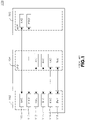
- FIG. 1 shows a typical protocol stack architecture for an LTE network in accordance with the prior art.
- the system may include a WTRU 102, an e Node-B (eNB) 104 and an access gateway (aGW) 106.
- a non access stratum (NAS) protocol 108 and a packet data convergence protocol 110 (PDCP) may reside in the WTRU 102 and the aGW 106 to allow for communication between the devices.
- a radio resource control (RRC) protocol 112, a radio link control (RLC) protocol 114, a medium access control (MAC) protocol 116 and a physical layer (PHY) 118 may reside in both the WTRU 102 and the eNB 104 to allow for communications between those devices.
- RRC radio resource control
- RLC radio link control
- MAC medium access control
- PHY physical layer
- the RRC protocol 112 may operate in two states: RRC_IDLE and RRC_CONNECTED. While in RRC_IDLE state the WTRU DRX cycle is configured by signaling over the NAS protocol 108. This state includes system information broadcasts, paging, and cell resection mobility. A WTRU in RRC_IDLE state preferably is allocated an ID number that identifies the WTRU in a tracking area. No RRC protocol context is stored in an eNB.
- the WTRU may make a connection with an E-UTRAN.
- the E-UTRAN knows the cell to which the WTRU belongs to so that the network can transmit and receive data to/from the WTRU.
- the network controls mobility (handover) and the WTRU conducts neighbor cell measurements.
- a WTRU can transmit and receive data to/from the network and monitors a control signaling channel for a shared data channel to see if any transmission over the shared data channel has been allocated to the WTRU.
- the WTRU also reports channel quality information and feedback information to the eNB.
- a DRX/discontinuous transmission (DTX) period can be configured according to WTRU activity level for power saving and efficient resource utilization. This is typically under control of the eNB.
- the NAS protocol 108 may operate in an LTE_DETACHED state, in which there is no RRC entity.
- the NAS protocol 108 may also operate in an LTE_IDLE state.
- the NAS protocol 108 may operate in an RRC_IDLE state, while in LTE_DETACHED state, during which some information may be stored in the WTRU and in the network, such as IP addresses, security associations, WTRU capability information and radio bearers. Decisions regarding state transitions are typically decided in the eNB or the aGW.
- the NAS protocol 108 may also operate in an LTE_ACTIVE state, which includes an RRC_CONNECTED state. In this state, state transitions are typically decided in the eNB or the aGW.
- LTE_ACTIVE state
- RRC_CONNECTED RRC_CONNECTED
- Some of the services that would run in the LTE_ACTIVE state are those services generating small packets on a regular basis, such as VoIP. Also, those services generating delay insensitive bulk packets on an infrequent basis, such as FTP, may run in the LTE_ACTIVE, as well as those services generating small packets on a rare basis, such as presence service.
- DRX cycle length should be long enough for battery power savings.
- the amount of data transmitted within a DRX cycle should be variable from cycle by cycle. For example, DRX for FTP service may allow an increase in the amount of data for each DRX cycle.
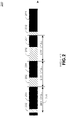
- FIG. 2 shows a DRX signal structure 200 in accordance with the prior art.
- An active period 202 is the period during when a WTRU's transmitter/receiver is turned on and a sleep period 204 is the period during when a WTRU's transmitter/receiver is turned off.
- a DRX cycle length 206 is the time distance between consecutive active period start positions.
- the DRX cycle length 206 may be determined by the network, considering the quality of service (QoS) requirements of a service activated in the WTRU. Active period start positions should be unambiguously identified by both the WTRU and the eNB.
- QoS quality of service
- the WTRU may monitor an L1/L2 control channel during a predefined time interval to see whether there is incoming data.
- a length of the active period 202 may be variable, depending on the amount of data to be transmitted during the DRX cycle 206.
- An end position of active period 202 may be explicitly signaled by the eNB or implicitly assumed after inactivity of the predefined time interval.
- Uplink data transmission can be initiated anytime during the sleep period 204. Active period uplink data transmission may end when the uplink transmission is completed.
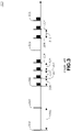
- FIG. 3 shows a two layer DRX method 300 in accordance with the prior art.
- the two layer method may be used to support flexible DRX and includes splitting the DRX signals into high level and low level.
- a high level DRX signal 302 is controlled by the RRC.
- the high level DRX interval 306 depends upon the basic flow requirements of the connection, for example, voice over IP, web browsing, and the like.
- the high level DRX interval 306 is preferably determined by the RRC in the eNB and is signaled to the WTRU using RRC control signaling.
- a low level DRX signal 304 is signaled by the MAC layer.
- a low level DRX interval 308 is flexible and may support fast changes in the DRX interval.
- a MAC header may carry information regarding low level settings.
- Dependence between the high level DRX 302 and low level DRX 304 should be at a minimum because the high level DRX interval 306 can be used as fallback DRX interval in case of any errors occur applying the lower level DRX interval 308.
- the network and the WTRU preferably are synchronized with the high layer DRX interval 306.
- the relatively long high level DRX interval 306 is beneficial for WTRU power savings, but limits downlink (DL) scheduling flexibility and throughput. If there is a significant amount of data buffered in an eNB or WTRU transmission buffer, it may be beneficial to change the short low level DRX interval 308 for a period of time suitable for the transmission of the buffered data. After the data transmission, the WTRU and the eNB could resume the high level DRX interval 302.
- DRX may be split between regular signals and interim signals.
- Table1 Active mode DRX control signaling RRC MAC Regular DRX control X Interim DRX control X
- Signaling DRX in the RRC is based on the regularity of the basic connection requirements and may result in a regular DRX signal ensuring the requirements of the connection.
- Regular DRX is determined in the eNB.
- a WTRU should know, through RRC signaling, to apply regular DRX. In other words, when a WTRU enters active mode, one of the RRC parameters delivered to the WTRU will be the regular DRX parameters to be applied. While in active mode the eNB can change, at any point in time and through RRC signaling, the regular DRX parameters used by the WTRU.
- FIG. 4 shows RRC signaling for regular DRX 400 in accordance with the prior art.
- An eNB 406 transmits an RRC signal 404 to a WTRU 402.
- the RRC signal 404 includes a regular DRX request.
- the WTRU 402 responds to the eNB 406 with an RRC signal 408 indicating that the WTRU received the regular DRX request.
- MAC layer DRX may be able to handle fast and irregular changes, such as, an instantaneous increase of data throughput, for example.
- the MAC layer interim DRX may be temporary. Interim DRX settings preferably are determined in the eNB.
- a WTRU acquires information regarding which interim DRX parameters to apply through MAC signaling.
- MAC signaling from the eNB to the WTRU may include interim DRX information.
- the WTRU may apply the interim DRX according to network instructions. Applying interim DRX does not affect the regular DRX interval. When a WTRU no longer applies interim DRX it will resume regular DRX.
- FIG. 5 shows MAC signaling 500 for regular DRX in accordance with the prior art.
- An e Node-B 506 transmits a MAC signal 504 to a WTRU 502.
- the MAC signal 504 includes DRX activation commands.
- the WTRU 502 responds to the eNB 506 with a hybrid automatic retransmit request (HARQ) process 508 indicating whether the WTRU received the activation commands.
- HARQ hybrid automatic retransmit request
- a method and apparatus for discontinuous reception (DRX) in a wireless transmit receive unit (WTRU) is disclosed.
- the method preferably includes a WTRU receiving DRX setting information over a radio resource control (RRC) signal, and the WTRU receiving DRX activation information over medium access control (MAC) signal.
- RRC radio resource control
- MAC medium access control
- the method may also include the WTRU grouping DRX setting information into a DRX profile and determining a DRX profile index associated with the DRX profile.
- the method may also include the WTRU, in a DRX minimum active period, receiving a data indication signal from an eNB and remaining in an active period based on the data indication signal.
- wireless transmit/receive unit includes but is not limited to a user equipment (UE), a mobile station, a fixed or mobile subscriber unit, a pager, a cellular telephone, a personal digital assistant (PDA), a computer, or any other type of user device capable of operating in a wireless environment.
- base station includes but is not limited to a Node-B, a site controller, an access point (AP), or any other type of interfacing device capable of operating in a wireless environment.
- Two layer DRX operation may include a regular DRX operation controlled by RRC signaling and an interim DRX operation controlled by MAC signaling.
- RRC signaling takes advantage of the reliability and robustness of RRC signaling in general. Reliability is achieved via response or acknowledgement messages that are generated at the RRC layer or via the use of the acknowledged mode (AM) service of the RLC layer. Also, ciphering and integrity protection are required for RRC signaling, thus making an RRC signal a reliable signal.
- a MAC signal is used for speed.
- MAC signaling is generally faster to generate and to process than RRC signaling.
- Interim DRX operations that use MAC signaling may be flexible, but do not include the reliability and security aspects that provided in RRC signaling and not MAC signaling.
- DRX signaling information can be classified into two categories: 1) DRX settings, parameters or configurations, such as DRX cycle periodicity, for example, and 2) DRX activation commands, such as to turn DRX on or off, for example.
- the DRX settings, parameters or configuration information preferably is signaled reliably, robustly, and securely.
- Interim DRX RRC signaling parameters and configuration information may be communicated via RRC signaling.
- DRX activation commands that, for example, instruct the WTRU to enter DRX mode, are preferably signaled quickly via MAC signaling.
- the commands to enter or exit interim DRX are signaled via MAC signaling.
- some DRX settings, parameters, or configuration information may be signaled with the DRX activation commands.
- FIG. 6a shows interim DRX setting signaling in accordance with one embodiment.
- Interim DRX setting information may be conveyed using RRC messages.
- a WTRU 602 receives an RRC signal 606 containing interim DRX setting information from an eNB 604.
- the WTRU 602 may respond to the eNB 604 with a confirmation signal 608.
- Figure 6b shows interim DRX activation signaling in accordance with one embodiment.
- the interim DRX activation signals are conveyed using MAC signals.
- the WTRU 602 receives a MAC signal 610 containing interim DRX activation information from an eNB 604.
- the WTRU 602 may respond to the eNB 604 with a hybrid automatic repeat request (HARQ) signal 612.
- HARQ hybrid automatic repeat request
- Sets of DRX setting information can be grouped to form a DRX profile.
- a DRX Profile ID may be used to indicate the DRX profile.
- RRC signaling may be used to define a DRX profile and attach it to a DRX Profile ID.
- the DRX profile may be used with interim DRX, regular DRX, or any other DRX mode.
- an eNB and a WTRU may exchange DRX activation commands that may reference an appropriate DRX Profile ID for the WTRU.
- the activation commands may be RRC signals, but are preferably MAC signals.
- the WTRU may dynamically apply the DRX parameter information in a particular DRX profile using MAC signaling that makes reference to the DRX profile ID, rather than having to specify and detail all DRX parameters.
- An interim DRX activation signal may reference a DRX Profile ID, or may contain some DRX settings that were not included in the RRC signaling. This signaling method may be applied to any level DRX or any type of DRX operation in general.
- a DRX cycle preferably contains an active period and a sleep period.
- the active period start positions may be unambiguously identified by both a WTRU and an eNB, while the active period length may be variable and depend on an amount of data to be transmitted during the DRX cycle.
- a DRX signaling message preferably specifies an activation time or a start time that is used to indicate a time to activate the DRX cycle or enter into DRX mode.
- An activation time can be indicated in absolute terms, or relative to the present time, to ensure that the both the WTRU and the eNB unambiguously identify the start of the DRX cycle.
- MAC or RRC signaling messages used for DRX preferably include a DRX activation or start time.
- a WTRU may remain in an awake DRX mode for a minimum active period.
- the minimum active period preferably is communicated in a DRX signaling message, either RRC or MAC, or it can be predefined.
- the minimum active period may ensure that if a WTRU has missed some transmissions it will soon be awake to receive them.
- DRX structure may be defined periodically, for example, one DRX cycle every 50 msec.
- another mode of DRX operation may be utilized whereby a DRX cycle start time is defined during a previous DRX cycle. This mode can be used independent of or in addition to the periodic mode of DRX operation.
- the eNB may instruct the WTRU via a signaling message, either MAC or RRC, to go to sleep for a predetermined time and/or wake up at a predetermined time.
- a DRX signaling message may be used to instruct the WTRU to stay awake until a specified time, such as, the next DRX cycle, for example.
- a WTRU may, by default, enter DRX once it is in the active/connected state.
- signaling messages may be used to exchange capability information regarding whether the WTRU supports DRX operation in the active/connected state.
- An eNB may obtain the WTRU's active mode DRX capability and any other parameters associated with such capability. Accordingly, the eNB may instruct the WTRU to go into active mode DRX as it deems necessary.
- a WTRU may remain awake for a minimum active period. During this period, the eNB may use Layer 1, Layer 2 or Layer 3 signaling messages to indicate whether data will be transmitted to the WTRU during a particular DRX cycle. The WTRU may stay in the active period until the beginning of the next DRX cycle. The WTRU will not sleep following the reception of its data until the beginning of the next DRX cycle.
- the WTRU may wait for an explicit signal from the eNB to indicate the presence of data for a particular WTRU. IF the WTRU does not receive an indication from the eNB, the WTRU may determine that no signal was transmitted or the signal went missing but shall stay awake because there might be something on the downlink for the WTRU
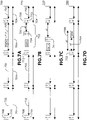
- FIG. 7a shows a signal diagram for DRX operation 700 in accordance with one embodiment.
- the DRX cycle 704 includes a minimum active time 710 and a sleep time 702.
- the WTRU may receive a command 708 in each minimum active time 710. If data is available for the WTRU, the WTRU receives an indication in the command 708, receives the data 712, and stays awake until the next DRX cycle 704.
- the eNB may interpret the lack of command as an indication that it can go back to sleep until the next DRX cycle, as it has no data to receive.
- Figure 7b shows a signal diagram for DRX operation 720 in accordance with another embodiment.
- the WTRU receives a command 708 during the minimum active time 710 indicating whether there is data for the WTRU. Once the WTRU receives the command that indicates that the eNB is transmitting during the DRX cycle 712, the WTRU exits DRX completely and may disregard its prior DRX operation and configuration. The WTRU may then stay awake in a non-DRX cycle 722.
- the eNB may use a signaling message 724 to instruct the WTRU to go back into DRX operation at time et 726.
- the signaling can be RRC, MAC, or PHY signaling, and a trigger to generate the signaling can be the detection of idle or inactivity time following a data transmission of data. Another trigger may be the eNB's knowledge that there are no more packets that need to be transmitted to the WTRU.
- the WTRU then resumes DRX operation and receives a command 708 during the next minimum active time 710 in the next DRX cycle 704.
- Figure 7c shows a signal diagram for DRX operation 740 in accordance with an alternative embodiment.
- the DRX signaling message that is used to activate DRX operation 744 may include a periodicity of the DRX cycle, that is, a DRX cycle time), a minimum active time, and a relative or/and absolute time when the WTRU should start or activate the DRX operation.
- the WTRU may go back into DRX operation at the next DRX cycle, as in Figure 7b , or after the next DRX cycle occurs, as in Figure 7c .
- a WTRU that is not in DRX mode may send a signaling message to an eNB indicating that the WTRU wants to enter DRX mode.
- the signaling can be RRC, MAC, or PHY signaling.
- the WTRU may use a trigger to generate the signaling, such as, the detection of an idle time or inactivity time following the reception of data by the WTRU, for example. There may be other triggers as well.
- the eNB Upon receiving the signaling message, the eNB generates a response signal to instruct the WTRU to go into DRX operation and the DRX settings.
- Figure 7d shows a signal diagram for DRX operation 760 in accordance with another alternative embodiment.
- a signaling message 762 indicates a relative or absolute time 764 when data transmission will begin and optionally, a relative or absolute time when data transmission will end 766.
- the WTRU stays in DRX mode.
- a DRX cycle is typically associated with a single WTRU.
- MBMS multimedia broadcast/multicast service
- RAN radio access network
- One-to-one signaling messages can be exchanged between the eNB and a WTRU to set up and confirm the MBMS DRX cycle.
- the MBMS DRX cycle can be set up via multicast or broadcast messages, for example, on a broadcast channel.
- the MBMS DRX cycle can be implicit or derived from a predetermined MBMS scheduling pattern.
- a WTRU may power down its MBMS transceiver during an MBMS DRX cycle.
- MBMS traffic can be scheduled with the DRX cycle of the WTRU. This scheme may be less flexible if there are many WTRUs involved in MBMS that have different DRX cycles, but may lead to increased efficiency since the WTRU will have aligned DRX and MBMS intervals.
- a WTRU transmits during pre-determined intervals, and sleeps during the rest. Coordination between DTX and DRX may be utilized, and the DRX and DTX intervals/cycles may coincide as much as possible, in order to allow maximum efficiency in power consumption. For example, uplink resource assignment can be done in a periodically. Aligning the uplink resource assignment with the DRX period may result in greater efficiency. In particular, periodic thin channel assignments can coincide with the DRX cycle.
- a WTRU may react too late to handover commands, which can cause complete failure of transmission and reception. Accordingly, the handover timing should be a consideration when the DRX cycle is determined, adjusted and signaled by an eNB.
- a measurement cycle may be required to be shorter than the normal DRX cycle in LTE active mode. Therefore, a signaling message may be sent to the WTRU to reconfigure the DRX cycle to reflect the WTRU being close to a cell edge.
- the DRX cycle should be turned off by the eNB by sending a signaling message or command to the WTRU.
- the WTRU may continuously monitor its own and its neighbor cell's reference signal, to, for example, prepare autonomous timing adjustment, or to prepare for any handover related activity.
- the WTRU preferably is not be put into DRX mode in order to give the WTRU a better chance to make measurements and try and sustain the call.
- WTRU mobility aspects may also be a factor to determine the DRX cycle in LTE active mode.
- Separate DRX settings may be implemented for different services, such as VoIP, web browsing traffic and the like.
- a WTRU may have multiple separate or independent DRX cycles for each of the services, or a WTRU may have a single DRX cycle whose DRX settings/parameters satisfy the most frequent traffic pattern. If multiple DRX cycles are used, the cycles may be aligned or coincide as much as possible, in order to maximize the potential for power savings.
- ROM read only memory
- RAM random access memory
- register cache memory
- semiconductor memory devices magnetic media such as internal hard disks and removable disks, magnetooptical media, and optical media such as CD-ROM disks, and digital versatile disks (DVDs).
- Suitable processors include, by way of example, a general purpose processor, a special purpose processor, a conventional processor, a digital signal processor (DSP), a plurality of microprocessors, one or more microprocessors in association with a DSP core, a controller, a microcontroller, Application Specific Integrated Circuits (ASICs), Field Programmable Gate Arrays (FPGAs) circuits, any other type of integrated circuit (IC), and/or a state machine.
- DSP digital signal processor
- ASICs Application Specific Integrated Circuits
- FPGAs Field Programmable Gate Arrays
- a processor in association with software may be used to implement a radio frequency transceiver for use in a wireless transmit receive unit (WTRU), user equipment (UE), terminal, base station, radio network controller (RNC), or any host computer.
- the WTRU may be used in conjunction with modules, implemented in hardware and/or software, such as a camera, a video camera module, a videophone, a speakerphone, a vibration device, a speaker, a microphone, a television transceiver, a hands free headset, a keyboard, a Bluetooth ® module, a frequency modulated (FM) radio unit, a liquid crystal display (LCD) display unit, an organic light-emitting diode (OLED) display unit, a digital music player, a media player, a video game player module, an Internet browser, and/or any wireless local area network (WLAN) module.
- modules implemented in hardware and/or software, such as a camera, a video camera module, a videophone, a speakerphone, a vibration device, a speaker
Abstract
Description
- The present invention relates to wireless communication systems. More particularly, a method and apparatus is disclosed for enhancing discontinuous reception (DRX) in wireless systems.
- A goal of the Long Term Evolution (LTE) program of the Third Generation Partnership Project (3GPP) is to bring new technology, network architecture, configurations and applications and services to wireless networks in order to provide improved spectral efficiency, reduced latency, faster user experiences and richer applications and services with less cost. LTE's aim is to create an Evolved Universal Terrestrial Radio Access Network (E-UTRAN).
- In an LTE compliant network, discontinuous reception (DRX) operation is used by a wireless transmit/receive unit (WTRU) to save power. DRX allows the WTRU to sleep during regular intervals and wake up at specific time instances to verify if the network has data for it.
-
Figure 1 shows a typical protocol stack architecture for an LTE network in accordance with the prior art. The system may include a WTRU 102, an e Node-B (eNB) 104 and an access gateway (aGW) 106. A non access stratum (NAS)protocol 108 and a packet data convergence protocol 110 (PDCP) may reside in the WTRU 102 and the aGW 106 to allow for communication between the devices. A radio resource control (RRC)protocol 112, a radio link control (RLC)protocol 114, a medium access control (MAC)protocol 116 and a physical layer (PHY) 118 may reside in both the WTRU 102 and the eNB 104 to allow for communications between those devices. - The RRC
protocol 112 may operate in two states: RRC_IDLE and RRC_CONNECTED. While in RRC_IDLE state the WTRU DRX cycle is configured by signaling over theNAS protocol 108. This state includes system information broadcasts, paging, and cell resection mobility. A WTRU in RRC_IDLE state preferably is allocated an ID number that identifies the WTRU in a tracking area. No RRC protocol context is stored in an eNB. - In the RRC_CONNECTED state, the WTRU may make a connection with an E-UTRAN. The E-UTRAN knows the cell to which the WTRU belongs to so that the network can transmit and receive data to/from the WTRU. In the RRC_CONNECTED state, the network controls mobility (handover) and the WTRU conducts neighbor cell measurements. Furthermore, at the RLC/MAC level, a WTRU can transmit and receive data to/from the network and monitors a control signaling channel for a shared data channel to see if any transmission over the shared data channel has been allocated to the WTRU. The WTRU also reports channel quality information and feedback information to the eNB. A DRX/discontinuous transmission (DTX) period can be configured according to WTRU activity level for power saving and efficient resource utilization. This is typically under control of the eNB.
- The NAS
protocol 108 may operate in an LTE_DETACHED state, in which there is no RRC entity. The NASprotocol 108 may also operate in an LTE_IDLE state. Also, the NASprotocol 108 may operate in an RRC_IDLE state, while in LTE_DETACHED state, during which some information may be stored in the WTRU and in the network, such as IP addresses, security associations, WTRU capability information and radio bearers. Decisions regarding state transitions are typically decided in the eNB or the aGW. - The NAS
protocol 108 may also operate in an LTE_ACTIVE state, which includes an RRC_CONNECTED state. In this state, state transitions are typically decided in the eNB or the aGW. - DRX may be activated in LTE_ACTIVE state, which corresponds to the RRC_CONNECTED state. Some of the services that would run in the LTE_ACTIVE state are those services generating small packets on a regular basis, such as VoIP. Also, those services generating delay insensitive bulk packets on an infrequent basis, such as FTP, may run in the LTE_ACTIVE, as well as those services generating small packets on a rare basis, such as presence service.
- Based on the characteristics of the aforementioned services, data transmission/reception may be performed during DRX operation without RRC signaling. Also, a DRX cycle length should be long enough for battery power savings. Furthermore, the amount of data transmitted within a DRX cycle should be variable from cycle by cycle. For example, DRX for FTP service may allow an increase in the amount of data for each DRX cycle.
-
Figure 2 shows aDRX signal structure 200 in accordance with the prior art. Anactive period 202 is the period during when a WTRU's transmitter/receiver is turned on and asleep period 204 is the period during when a WTRU's transmitter/receiver is turned off. ADRX cycle length 206 is the time distance between consecutive active period start positions. - The
DRX cycle length 206 may be determined by the network, considering the quality of service (QoS) requirements of a service activated in the WTRU. Active period start positions should be unambiguously identified by both the WTRU and the eNB. - At an active period start position, the WTRU may monitor an L1/L2 control channel during a predefined time interval to see whether there is incoming data. A length of the
active period 202 may be variable, depending on the amount of data to be transmitted during theDRX cycle 206. An end position ofactive period 202 may be explicitly signaled by the eNB or implicitly assumed after inactivity of the predefined time interval. Uplink data transmission can be initiated anytime during thesleep period 204. Active period uplink data transmission may end when the uplink transmission is completed. -
Figure 3 shows a twolayer DRX method 300 in accordance with the prior art. The two layer method may be used to support flexible DRX and includes splitting the DRX signals into high level and low level. Referring toFigure 3 , a highlevel DRX signal 302 is controlled by the RRC. The highlevel DRX interval 306 depends upon the basic flow requirements of the connection, for example, voice over IP, web browsing, and the like. The highlevel DRX interval 306 is preferably determined by the RRC in the eNB and is signaled to the WTRU using RRC control signaling. - A low
level DRX signal 304 is signaled by the MAC layer. A lowlevel DRX interval 308 is flexible and may support fast changes in the DRX interval. A MAC header may carry information regarding low level settings. - Dependence between the
high level DRX 302 andlow level DRX 304 should be at a minimum because the highlevel DRX interval 306 can be used as fallback DRX interval in case of any errors occur applying the lowerlevel DRX interval 308. The network and the WTRU preferably are synchronized with the highlayer DRX interval 306. - The relatively long high
level DRX interval 306 is beneficial for WTRU power savings, but limits downlink (DL) scheduling flexibility and throughput. If there is a significant amount of data buffered in an eNB or WTRU transmission buffer, it may be beneficial to change the short lowlevel DRX interval 308 for a period of time suitable for the transmission of the buffered data. After the data transmission, the WTRU and the eNB could resume the highlevel DRX interval 302. - As shown in Table 1, DRX may be split between regular signals and interim signals.
Table1: Active mode DRX control signaling RRC MAC Regular DRX control X Interim DRX control X - Signaling DRX in the RRC is based on the regularity of the basic connection requirements and may result in a regular DRX signal ensuring the requirements of the connection. Regular DRX is determined in the eNB. A WTRU should know, through RRC signaling, to apply regular DRX. In other words, when a WTRU enters active mode, one of the RRC parameters delivered to the WTRU will be the regular DRX parameters to be applied. While in active mode the eNB can change, at any point in time and through RRC signaling, the regular DRX parameters used by the WTRU.
-
Figure 4 shows RRC signaling forregular DRX 400 in accordance with the prior art. AneNB 406 transmits anRRC signal 404 to aWTRU 402. TheRRC signal 404 includes a regular DRX request. TheWTRU 402 responds to theeNB 406 with anRRC signal 408 indicating that the WTRU received the regular DRX request. - MAC layer DRX may be able to handle fast and irregular changes, such as, an instantaneous increase of data throughput, for example. The MAC layer interim DRX may be temporary. Interim DRX settings preferably are determined in the eNB. A WTRU acquires information regarding which interim DRX parameters to apply through MAC signaling. MAC signaling from the eNB to the WTRU may include interim DRX information. The WTRU may apply the interim DRX according to network instructions. Applying interim DRX does not affect the regular DRX interval. When a WTRU no longer applies interim DRX it will resume regular DRX.
-
Figure 5 shows MAC signaling 500 for regular DRX in accordance with the prior art. An e Node-B 506 transmits aMAC signal 504 to aWTRU 502. TheMAC signal 504 includes DRX activation commands. TheWTRU 502 responds to theeNB 506 with a hybrid automatic retransmit request (HARQ)process 508 indicating whether the WTRU received the activation commands. - A method and apparatus for discontinuous reception (DRX) in a wireless transmit receive unit (WTRU) is disclosed. The method preferably includes a WTRU receiving DRX setting information over a radio resource control (RRC) signal, and the WTRU receiving DRX activation information over medium access control (MAC) signal. The method may also include the WTRU grouping DRX setting information into a DRX profile and determining a DRX profile index associated with the DRX profile. The method may also include the WTRU, in a DRX minimum active period, receiving a data indication signal from an eNB and remaining in an active period based on the data indication signal.
- A more detailed understanding may be had from the following description, given by way of example and to be understood in conjunction with the accompanying drawings wherein:
-
Figure 1 shows a typical protocol stack architecture for an LTE network in accordance with the prior art; -
Figure 2 shows a DRX signal structure in accordance with the prior art; -
Figure 3 shows a two layer DRX method in accordance with the prior art; -
Figure 4 shows regular DRX signaling in accordance with the prior art; -
Figure 5 shows interim DRX signaling in accordance with the prior art; -
Figure 6a shows DRX settings information signaling in accordance with one embodiment; -
Figure 6b shows DRX activation information signaling in accordance with one embodiment; -
Figure 7a is a signal diagram of DRX operation in accordance with one embodiment; -
Figure 7b is a signal diagram of DRX operation in accordance with an alternative embodiment; -
Figure 7c is a signal diagram of DRX operation in accordance with another embodiment; and -
Figure 7d is a signal diagram of DRX operation in accordance with yet another embodiment. - When referred to hereafter, the terminology "wireless transmit/receive unit (WTRU)" includes but is not limited to a user equipment (UE), a mobile station, a fixed or mobile subscriber unit, a pager, a cellular telephone, a personal digital assistant (PDA), a computer, or any other type of user device capable of operating in a wireless environment. When referred to hereafter, the terminology "base station" includes but is not limited to a Node-B, a site controller, an access point (AP), or any other type of interfacing device capable of operating in a wireless environment.
- Two layer DRX operation may include a regular DRX operation controlled by RRC signaling and an interim DRX operation controlled by MAC signaling. The use of RRC signaling takes advantage of the reliability and robustness of RRC signaling in general. Reliability is achieved via response or acknowledgement messages that are generated at the RRC layer or via the use of the acknowledged mode (AM) service of the RLC layer. Also, ciphering and integrity protection are required for RRC signaling, thus making an RRC signal a reliable signal.
- A MAC signal is used for speed. MAC signaling is generally faster to generate and to process than RRC signaling. Interim DRX operations that use MAC signaling may be flexible, but do not include the reliability and security aspects that provided in RRC signaling and not MAC signaling.
- DRX signaling information can be classified into two categories: 1) DRX settings, parameters or configurations, such as DRX cycle periodicity, for example, and 2) DRX activation commands, such as to turn DRX on or off, for example.
- The DRX settings, parameters or configuration information preferably is signaled reliably, robustly, and securely. Interim DRX RRC signaling parameters and configuration information may be communicated via RRC signaling. However, DRX activation commands that, for example, instruct the WTRU to enter DRX mode, are preferably signaled quickly via MAC signaling. For example, the commands to enter or exit interim DRX are signaled via MAC signaling.
- In an alternative, some DRX settings, parameters, or configuration information may be signaled with the DRX activation commands.
-
Figure 6a shows interim DRX setting signaling in accordance with one embodiment. Interim DRX setting information may be conveyed using RRC messages. AWTRU 602 receives anRRC signal 606 containing interim DRX setting information from aneNB 604. TheWTRU 602 may respond to theeNB 604 with aconfirmation signal 608. -
Figure 6b shows interim DRX activation signaling in accordance with one embodiment. The interim DRX activation signals are conveyed using MAC signals. TheWTRU 602 receives aMAC signal 610 containing interim DRX activation information from aneNB 604. TheWTRU 602 may respond to theeNB 604 with a hybrid automatic repeat request (HARQ)signal 612. - Sets of DRX setting information can be grouped to form a DRX profile. A DRX Profile ID may be used to indicate the DRX profile. RRC signaling may be used to define a DRX profile and attach it to a DRX Profile ID. The DRX profile may be used with interim DRX, regular DRX, or any other DRX mode. Once the profiles are setup or preconfigured, an eNB and a WTRU may exchange DRX activation commands that may reference an appropriate DRX Profile ID for the WTRU. The activation commands may be RRC signals, but are preferably MAC signals.
- The WTRU may dynamically apply the DRX parameter information in a particular DRX profile using MAC signaling that makes reference to the DRX profile ID, rather than having to specify and detail all DRX parameters. An interim DRX activation signal may reference a DRX Profile ID, or may contain some DRX settings that were not included in the RRC signaling. This signaling method may be applied to any level DRX or any type of DRX operation in general.
- A DRX cycle preferably contains an active period and a sleep period. The active period start positions may be unambiguously identified by both a WTRU and an eNB, while the active period length may be variable and depend on an amount of data to be transmitted during the DRX cycle.
- A DRX signaling message preferably specifies an activation time or a start time that is used to indicate a time to activate the DRX cycle or enter into DRX mode. An activation time can be indicated in absolute terms, or relative to the present time, to ensure that the both the WTRU and the eNB unambiguously identify the start of the DRX cycle. MAC or RRC signaling messages used for DRX preferably include a DRX activation or start time.
- A WTRU may remain in an awake DRX mode for a minimum active period. The minimum active period preferably is communicated in a DRX signaling message, either RRC or MAC, or it can be predefined. The minimum active period may ensure that if a WTRU has missed some transmissions it will soon be awake to receive them.
- DRX structure may be defined periodically, for example, one DRX cycle every 50 msec. In order to increase the flexibility of DRX, another mode of DRX operation may be utilized whereby a DRX cycle start time is defined during a previous DRX cycle. This mode can be used independent of or in addition to the periodic mode of DRX operation. As an example, during the active period of a DRX cycle, once the WTRU has received its intended data and there are no further packets to transmit to that WTRU at the eNB, the eNB may instruct the WTRU via a signaling message, either MAC or RRC, to go to sleep for a predetermined time and/or wake up at a predetermined time.
- Additionally, it may be advantageous under certain circumstances to keep the WTRU awake during a DRX cycle instead of allowing it to go to sleep until the next DRX cycle. In order to achieve that, a DRX signaling message, either MAC or RRC, may be used to instruct the WTRU to stay awake until a specified time, such as, the next DRX cycle, for example.
- A WTRU may, by default, enter DRX once it is in the active/connected state. As an alternative, signaling messages may be used to exchange capability information regarding whether the WTRU supports DRX operation in the active/connected state. An eNB may obtain the WTRU's active mode DRX capability and any other parameters associated with such capability. Accordingly, the eNB may instruct the WTRU to go into active mode DRX as it deems necessary.
- A WTRU may remain awake for a minimum active period. During this period, the eNB may use Layer 1,
Layer 2 orLayer 3 signaling messages to indicate whether data will be transmitted to the WTRU during a particular DRX cycle. The WTRU may stay in the active period until the beginning of the next DRX cycle. The WTRU will not sleep following the reception of its data until the beginning of the next DRX cycle. - The WTRU may wait for an explicit signal from the eNB to indicate the presence of data for a particular WTRU. IF the WTRU does not receive an indication from the eNB, the WTRU may determine that no signal was transmitted or the signal went missing but shall stay awake because there might be something on the downlink for the WTRU
-
Figure 7a shows a signal diagram forDRX operation 700 in accordance with one embodiment. TheDRX cycle 704 includes a minimumactive time 710 and asleep time 702. The WTRU may receive acommand 708 in each minimumactive time 710. If data is available for the WTRU, the WTRU receives an indication in thecommand 708, receives thedata 712, and stays awake until thenext DRX cycle 704. - In an alternative embodiment, if the eNB has not or will not transmit data for the WTRU during this DRX cycle, it does not send the
command 708. The WTRU may interpret the lack of command as an indication that it can go back to sleep until the next DRX cycle, as it has no data to receive. -
Figure 7b shows a signal diagram forDRX operation 720 in accordance with another embodiment. The WTRU receives acommand 708 during the minimumactive time 710 indicating whether there is data for the WTRU. Once the WTRU receives the command that indicates that the eNB is transmitting during theDRX cycle 712, the WTRU exits DRX completely and may disregard its prior DRX operation and configuration. The WTRU may then stay awake in anon-DRX cycle 722. The eNB may use asignaling message 724 to instruct the WTRU to go back into DRX operation attime et 726. The signaling can be RRC, MAC, or PHY signaling, and a trigger to generate the signaling can be the detection of idle or inactivity time following a data transmission of data. Another trigger may be the eNB's knowledge that there are no more packets that need to be transmitted to the WTRU. The WTRU then resumes DRX operation and receives acommand 708 during the next minimumactive time 710 in thenext DRX cycle 704. -
Figure 7c shows a signal diagram forDRX operation 740 in accordance with an alternative embodiment. The DRX signaling message that is used to activateDRX operation 744 may include a periodicity of the DRX cycle, that is, a DRX cycle time), a minimum active time, and a relative or/and absolute time when the WTRU should start or activate the DRX operation. The WTRU may go back into DRX operation at the next DRX cycle, as inFigure 7b , or after the next DRX cycle occurs, as inFigure 7c . - A WTRU that is not in DRX mode may send a signaling message to an eNB indicating that the WTRU wants to enter DRX mode. The signaling can be RRC, MAC, or PHY signaling. The WTRU may use a trigger to generate the signaling, such as, the detection of an idle time or inactivity time following the reception of data by the WTRU, for example. There may be other triggers as well. Upon receiving the signaling message, the eNB generates a response signal to instruct the WTRU to go into DRX operation and the DRX settings.
-
Figure 7d shows a signal diagram forDRX operation 760 in accordance with another alternative embodiment. Asignaling message 762 indicates a relative orabsolute time 764 when data transmission will begin and optionally, a relative or absolute time when data transmission will end 766. The WTRU stays in DRX mode. - A DRX cycle is typically associated with a single WTRU. However, for multimedia broadcast/multicast service (MBMS), it is difficult to broadcast to multiple WTRU's that have different DRX cycles. Therefore, an eNB or a radio access network (RAN) may define an "MBMS DRX" cycle that is common for a group of WTRU's. One-to-one signaling messages can be exchanged between the eNB and a WTRU to set up and confirm the MBMS DRX cycle. In an alternative embodiment, the MBMS DRX cycle can be set up via multicast or broadcast messages, for example, on a broadcast channel. In another alternative embodiment, the MBMS DRX cycle can be implicit or derived from a predetermined MBMS scheduling pattern. A WTRU may power down its MBMS transceiver during an MBMS DRX cycle.
- It is preferable to coordinate between the MBMS traffic or the MBMS DRX cycle and the WTRU's normal DRX cycle. For example, MBMS traffic can be scheduled with the DRX cycle of the WTRU. This scheme may be less flexible if there are many WTRUs involved in MBMS that have different DRX cycles, but may lead to increased efficiency since the WTRU will have aligned DRX and MBMS intervals.
- During DTX, a WTRU transmits during pre-determined intervals, and sleeps during the rest. Coordination between DTX and DRX may be utilized, and the DRX and DTX intervals/cycles may coincide as much as possible, in order to allow maximum efficiency in power consumption. For example, uplink resource assignment can be done in a periodically. Aligning the uplink resource assignment with the DRX period may result in greater efficiency. In particular, periodic thin channel assignments can coincide with the DRX cycle.
- System messages related to handover are critical. If a DRX cycle is too long, a WTRU may react too late to handover commands, which can cause complete failure of transmission and reception. Accordingly, the handover timing should be a consideration when the DRX cycle is determined, adjusted and signaled by an eNB.
- For example, when a WTRU is close to a cell edge a measurement cycle may be required to be shorter than the normal DRX cycle in LTE active mode. Therefore, a signaling message may be sent to the WTRU to reconfigure the DRX cycle to reflect the WTRU being close to a cell edge.
- Also, when a neighbor cell's measurements are strong, meaning it is a high probability that handover may occur, the DRX cycle should be turned off by the eNB by sending a signaling message or command to the WTRU. The WTRU may continuously monitor its own and its neighbor cell's reference signal, to, for example, prepare autonomous timing adjustment, or to prepare for any handover related activity. In general, when the serving cell's signal strength or transmission quality indicator is below a certain threshold, the WTRU preferably is not be put into DRX mode in order to give the WTRU a better chance to make measurements and try and sustain the call.
- WTRU mobility aspects may also be a factor to determine the DRX cycle in LTE active mode. Separate DRX settings may be implemented for different services, such as VoIP, web browsing traffic and the like. A WTRU may have multiple separate or independent DRX cycles for each of the services, or a WTRU may have a single DRX cycle whose DRX settings/parameters satisfy the most frequent traffic pattern. If multiple DRX cycles are used, the cycles may be aligned or coincide as much as possible, in order to maximize the potential for power savings.
-
- 1. A method of discontinuous reception (DRX) in a wireless transmit receive unit (WTRU), the method comprising the WTRU receiving DRX setting information over a radio resource control (RRC) signal.
- 2. The method as in embodiment 1 further comprising the WTRU receiving DRX activation information over medium access control (MAC) signal.
- 3. The method as in
embodiment 1 or 2 further comprising grouping DRX setting information into a DRX profile. - 4. The method as in
embodiment 3 further comprising determining a DRX profile index associated with the DRX profile. - 5. The method as in
embodiment 4 further comprising the WTRU receiving the DRX profile over RRC signaling. - 6. A method of discontinuous reception (DRX) in a wireless communication system, the method comprising a wireless transmit receive unit (WTRU) in a DRX minimum active period receiving a data indication signal from an e Node-B (eNB).
- 7. The method as in embodiment 6 further comprising the WTRU remaining in an active period based on the data indication signal.
- 8. The method as in embodiment 6 or 7 further comprising the WTRU discontinuing DRX operation based on the data indication signal.
- 9. The method as in embodiment 6, 7 or 8 further comprising the WTRU resuming DRX operation based on a received signal from an eNB after data reception.
- 10. The method as in any one of embodiments 6-9 further comprising the WTRU transmitting a signal to the eNB, wherein the signal comprises a request to enter DRX mode.
- 11. The method as in embodiment 10 further comprising the WTRU transmitting the signal to the eNB based on a trigger.
- 12. The method as in embodiment 10 or 11 further comprising the eNB responding to the signal with a second signal, wherein the second signal comprises DRX settings information.
- 13. The method as in any one of embodiments 6-12 wherein the data indication signal comprises a DRX start time.
- 14. The method as in any one of embodiments 6-12 wherein the data indication signal comprises a DRX cycle time, a DRX minimum activation time, and a DRX start time.
- 15. The method as in any one of embodiments 6-14 further comprising the WTRU discontinuing DRX operation based on the data indication signal.
- 16. The method as in any one of embodiments 6-15 further comprisnig the WTRU resuming DRX operation at a start of a regular DRX cycle.
- 17. The method as in any one of embodiments 6-16 wherein the data indication signal comprises a data transmission start time and an indication of a temporal length of the data transmission.
- 18. A method of discontinuous reception and discontinuous transmission in a wireless communication system, the method comprising coordinating DRX and discontinuous transmission (DTX) cycles such that the DRX and DTX cycles coincide.
- 19. The method as in embodiment 18 wherein a DRX measurement cycle is dependent on a distance of a wireless transmit receive unit (WTRU) from a cell edge.
- 20. The method as in any one of embodiment 19 further comprising the WTRU discontinuing DRX mode based on a serving cell strength falling below a threshold.
- 21. The method as in any one of embodiments 18-20 further comprising determining a separate DRX cycle for certain services, wherein the certain services comprise voice-over-IP (VOIP) and web browsing.
- 22. A wireless transmit receive unit (WTRU) configured to receive discontinuous reception (DRX) setting information in an radio resource control (RRC) signal.
- 23. The WTRU as in
embodiment 22 further configured to receive DRX activation information in a medium access control (MAC) signal. - 24. The WTRU as in
embodiment 22 or 23 wherein the WTRU is further configured to receive a data indication signal from an e Node-B (eNB) while the WTRU is in a DRX minimum active period. - 25. The WTRU as in embodiment 24 wherein the WTRU is further configured to remain in an active period based on the data indication signal.
- 26. The WTRU as in embodiment 23 or 24 wherein the WTRU is further configured to discontinue DRX operation based on the data indication signal.
- 27. The WTRU as in any one of embodiments 24-26 wherein the WTRU is further configured to resume DRX operation based on a received signal from an eNB after data reception.
- 28. The WTRU as in embodiment 27 wherein the WTRU is further configured to transmit a signal to the eNB, wherein the signal comprises a request to enter DRX mode.
- 29. The WTRU as in embodiment 27 or 28 wherein the WTRU is further configured to transmit the signal to the eNB based on a trigger.
- 30. The WTRU as in any one of embodiments 24-29 wherein the WTRU is further configured to discontinue DRX operation based on the data indication signal.
- 31. The WTRU as in any one of embodiments 24-30 wherein the WTRU is further configured to resume DRX operation at a start of a regular DRX cycle.
- 32. The WTRU as in any one of embodiments 24-31 wherein the WTRU is further configured to measure an activity time following reception of data.
- 33. The WTRU as in embodiment 32 wherein the WTRU is further configured to determine DRX operation start based on the inactivity time.
- 34. The WTRU as in any one of embodiments 24-33 wherein the WTRU is further configured to remain in DRX operation for a minimum active period.
- Although the features and elements are described in the preferred embodiments in particular combinations, each feature or element can be used alone without the other features and elements of the preferred embodiments or in various combinations with or without other features and elements. The methods or flow charts provided may be implemented in a computer program, software, or firmware tangibly embodied in a computer-readable storage medium for execution by a general purpose computer or a processor. Examples of computer-readable storage mediums include a read only memory (ROM), a random access memory (RAM), a register, cache memory, semiconductor memory devices, magnetic media such as internal hard disks and removable disks, magnetooptical media, and optical media such as CD-ROM disks, and digital versatile disks (DVDs).
- Suitable processors include, by way of example, a general purpose processor, a special purpose processor, a conventional processor, a digital signal processor (DSP), a plurality of microprocessors, one or more microprocessors in association with a DSP core, a controller, a microcontroller, Application Specific Integrated Circuits (ASICs), Field Programmable Gate Arrays (FPGAs) circuits, any other type of integrated circuit (IC), and/or a state machine.
- A processor in association with software may be used to implement a radio frequency transceiver for use in a wireless transmit receive unit (WTRU), user equipment (UE), terminal, base station, radio network controller (RNC), or any host computer. The WTRU may be used in conjunction with modules, implemented in hardware and/or software, such as a camera, a video camera module, a videophone, a speakerphone, a vibration device, a speaker, a microphone, a television transceiver, a hands free headset, a keyboard, a Bluetooth® module, a frequency modulated (FM) radio unit, a liquid crystal display (LCD) display unit, an organic light-emitting diode (OLED) display unit, a digital music player, a media player, a video game player module, an Internet browser, and/or any wireless local area network (WLAN) module.
-
- 1. A method of discontinuous reception (DRX) in a wireless transmit receive unit (WTRU), the method comprising:
- the WTRU receiving DRX setting information over a radio resource control (RRC) signal; and
- the WTRU receiving DRX activation information over medium access control (MAC) signal.
- 2. The method as in item 1 further comprising grouping DRX setting information into a DRX profile.
- 3. The method as in
item 2 further comprising determining a DRX profile index associated with the DRX profile. - 4. The method as in
item 3 furhter comprising the WTRU receiving the DRX profile over RRC signaling. - 5. A method of discontinuous reception (DRX) in a wireless communication system, the method comprising:
- a wireless transmit receive unit (WTRU) in a DRX minimum active period receiving a data indication signal from an e Node-B (eNB); and
- the WTRU remaining in an active period based on the data indication signal.
- 6. The method as in item 5 further comprising:
- the WTRU discontinuing DRX operation based on the data indication signal; and
- the WTRU resuming DRX operation based on a received signal from an eNB after data reception.
- 7. The method as in item 5 further comprising the WTRU transmitting a signal to the eNB, wherein the signal comprises a request to enter DRX mode.
- 8. The method as in item 7 further comprising the WTRU transmitting the signal to the eNB based on a trigger.
- 9. The method as in item 7 further comprising the eNB responding to the signal with a second signal, wherein the second signal comprises DRX settings information.
- 10. The method as in item 5 wherein the data indication signal comprises a DRX start time.
- 11. The method as in item 5 wherein the data indication signal comprises a DRX cycle time, a DRX minimum activation time, and a DRX start time.
- 12. The method as in item 5 further comprising:
- the WTRU discontinuing DRX operation based on the data indication signal; and
- the WTRU resuming DRX operation at a start of a regular DRX cycle.
- 13. The method as in item 5 wherein the data indication signal comprises a data transmission start time and an indication of a temporal length of the data transmission.
- 14. A method of discontinuous reception and discontinuous transmission in a wireless communication system, the method comprising coordinating DRX and discontinuous transmission (DTX) cycles such that the DRX and DTX cycles coincide.
- 15. The method as in item 5 wherein a DRX measurement cycle is dependent on a distance of a wireless transmit receive unit (WTRU) from a cell edge.
- 16. The method as in item 14 further comprising the WTRU discontinuing DRX mode based on a serving cell strength falling below a threshold.
- 17. The method as in item 14 further comprising determining a separate DRX cycle for certain services, wherein the certain services comprise voice-over-IP (VOIP) and web browsing.
- 18. A wireless transmit receive unit (WTRU) configured to:
- receive discontinuous reception (DRX) setting information in an radio resource control (RRC) signal; and
- receive DRX activation information in a medium access control (MAC) signal.
- 19. The WTRU as in item 18 wherein the WTRU is further configured to:
- receive a data indication signal from an e Node-B (eNB) while the WTRU is in a DRX minimum active period; and
- remain in an active period based on the data indication signal.
- 20. The WTRU as in item 18 wherein the WTRU is further configured to:
- discontinue DRX operation based on the data indication signal; and
- resume DRX operation based on a received signal from an eNB after data reception.
- 21. The WTRU as in item 18 wherein the WTRU is further configured to transmit a signal to the eNB, wherein the signal comprises a request to enter DRX mode.
- 22. The WTRU as in item 21 wherein the WTRU is further configured to transmit the signal to the eNB based on a trigger.
- 23. The WTRU as in item 18 wherein the WTRU is further configured to:
- discontinue DRX operation based on the data indication signal; and
- resume DRX operation at a start of a regular DRX cycle.
- 24. The WTRU as in item 18 wherein the WTRU is further configured to:
- measure an inactivity time following reception of data; and
- determine DRX operation start based on the inactivity time.
- 25. The WTRU as in item 18 wherein the WTRU is further configured to:
remain in DRX operation for a minimum active period.
Claims (15)
- A method implemented by a wireless transmit receive unit, WTRU, the method comprising:the WTRU receiving a radio resource control, RRC, message, the RRC message comprising discontinuous reception, DRX, configuration information, the DRX configuration information comprising an indication of a DRX cycle periodicity and an indication of a length of a DRX minimum active period;the WTRU receiving a data indication signal during the DRX minimum active period of a DRX cycle, the data indication signal indicating that downlink data is to be sent to the WTRU, wherein an active period of the DRX cycle is of variable length depending on an amount of data transmissions sent to the WTRU;the WTRU receiving the downlink data; andthe WTRU receiving a medium access control, MAC, message that indicates the end of the active period of the DRX cycle.
- A wireless transmit receive unit, WTRU, comprising:means for receiving a radio resource control, RRC, message, the RRC message comprising discontinuous reception, DRX, configuration information, the DRX configuration information comprising an indication of a DRX cycle periodicity and an indication of a length of a DRX minimum active period;means for receiving a data indication signal during the DRX minimum active period of a DRX cycle, the data indication signal indicating that downlink data is to be sent to the WTRU, wherein an active period of the DRX cycle is of variable length depending on an amount of data transmissions sent to the WTRU;means for receiving the downlink data; andmeans for receiving a medium access control, MAC, message that indicates the end of the active period of the DRX cycle.
- The method as in claim 1 or the WTRU as in claim 2, wherein the MAC message indicates that the WTRU can go to sleep until the start of a subsequent DRX cycle.
- The method as in claim 1 or the WTRU as in claim 2, wherein the MAC message indicates that the WTRU can go to sleep for a period of time.
- The method as in claim 1 or the WTRU as in claim 2, wherein the minimum active period of the DRX cycle corresponds to length of time the WTRU wakes up to monitor for data indication signals during the DRX cycle absent explicit instructions that the WTRU can go to sleep.
- The method as in claim 1 or the WTRU as in claim 2, wherein the data indication signal is received via a Layer 1 control channel.
- The method as in claim 1 or the WTRU as in claim 2, wherein the WTRU monitors for data indication messages during the DRX minimum active period of a subsequent DRX cycle, and the WTRU determines that it can go to sleep at the end of the minimum active period of the subsequent DRX cycle based on no data indication signal being received during the minimum active period of the subsequent DRX cycle.
- The method as in claim 1 or the WTRU as in claim 2, wherein the DRX configuration information comprises an indication of a DRX cycle start time.
- The method as in claim 1 or the WTRU as in claim 2, wherein the DRX configuration information comprises an indication of a DRX cycle start time, and the minimum active period of the DRX cycle begins at a time indicated by a DRX cycle start time.
- The method as in claim 1 or the WTRU as in claim 2, wherein a periodic uplink allocation is configured to be aligned with the minimum active period of the DRX cycle.
- The method as in claim 1 or the WTRU as in claim 2, wherein MAC message is used to explicitly end the active period of the DRX cycle.
- The method as in claim 1 or the WTRU as in claim 2, wherein the WTRU sends an uplink transmission during the minimum active period of the DRX cycle.
- The method as in claim 1 or the WTRU as in claim 2, wherein the WTRU resumes DRX operation based on receiving the MAC message.
- The method as in claim 1 or the WTRU as in claim 2, wherein the WTRU resuming DRX operation based on receiving the MAC message comprises the WTRU going to sleep based on receiving the MAC message.
- A device comprising:means for sending a radio resource control, RRC, message to a wireless transmit/receive unit WTRU, the RRC message comprising discontinuous reception, DRX, configuration information, the DRX configuration information comprising an indication of a DRX cycle periodicity and an indication of a length of a DRX minimum active period;means for sending a data indication signal to the WTRU during the DRX minimum active period of a DRX cycle, the data indication signal indicating that downlink data is to be sent to the WTRU, wherein an active period of the DRX cycle is of variable length depending on an amount of data transmissions sent to the WTRU;means for sending the downlink data to the WTRU;means for sending a medium access control, MAC, message to the WTRU that indicates the end of the active period of the DRX cycle.
Applications Claiming Priority (5)
| Application Number | Priority Date | Filing Date | Title |
|---|---|---|---|
| US86318506P | 2006-10-27 | 2006-10-27 | |
| EP18158773.4A EP3373663B1 (en) | 2006-10-27 | 2007-10-25 | Method and apparatus for enhancing discontinuous reception in wireless systems |
| EP07839819.5A EP2090124B1 (en) | 2006-10-27 | 2007-10-25 | Method and apparatus for enhancing discontinuous reception in wireless systems |
| PCT/US2007/022759 WO2008057296A1 (en) | 2006-10-27 | 2007-10-25 | Method and apparatus for enhancing discontinuous reception in wireless systems |
| EP19199095.1A EP3664523B1 (en) | 2006-10-27 | 2007-10-25 | Method and apparatus for enhancing discontinuous reception in wireless systems |
Related Parent Applications (3)
| Application Number | Title | Priority Date | Filing Date |
|---|---|---|---|
| EP07839819.5A Division EP2090124B1 (en) | 2006-10-27 | 2007-10-25 | Method and apparatus for enhancing discontinuous reception in wireless systems |
| EP19199095.1A Division EP3664523B1 (en) | 2006-10-27 | 2007-10-25 | Method and apparatus for enhancing discontinuous reception in wireless systems |
| EP18158773.4A Division EP3373663B1 (en) | 2006-10-27 | 2007-10-25 | Method and apparatus for enhancing discontinuous reception in wireless systems |
Publications (1)
| Publication Number | Publication Date |
|---|---|
| EP4061066A1 true EP4061066A1 (en) | 2022-09-21 |
Family
ID=38955921
Family Applications (4)
| Application Number | Title | Priority Date | Filing Date |
|---|---|---|---|
| EP22172314.1A Pending EP4061066A1 (en) | 2006-10-27 | 2007-10-25 | Method and apparatus for enhancing discontinuous reception in wireless systems |
| EP18158773.4A Active EP3373663B1 (en) | 2006-10-27 | 2007-10-25 | Method and apparatus for enhancing discontinuous reception in wireless systems |
| EP07839819.5A Active EP2090124B1 (en) | 2006-10-27 | 2007-10-25 | Method and apparatus for enhancing discontinuous reception in wireless systems |
| EP19199095.1A Active EP3664523B1 (en) | 2006-10-27 | 2007-10-25 | Method and apparatus for enhancing discontinuous reception in wireless systems |
Family Applications After (3)
| Application Number | Title | Priority Date | Filing Date |
|---|---|---|---|
| EP18158773.4A Active EP3373663B1 (en) | 2006-10-27 | 2007-10-25 | Method and apparatus for enhancing discontinuous reception in wireless systems |
| EP07839819.5A Active EP2090124B1 (en) | 2006-10-27 | 2007-10-25 | Method and apparatus for enhancing discontinuous reception in wireless systems |
| EP19199095.1A Active EP3664523B1 (en) | 2006-10-27 | 2007-10-25 | Method and apparatus for enhancing discontinuous reception in wireless systems |
Country Status (20)
| Country | Link |
|---|---|
| US (7) | US8228829B2 (en) |
| EP (4) | EP4061066A1 (en) |
| JP (4) | JP5536455B2 (en) |
| KR (6) | KR20140136528A (en) |
| CN (2) | CN101611648B (en) |
| AR (1) | AR063439A1 (en) |
| AU (1) | AU2007318106A1 (en) |
| BR (1) | BRPI0716323B1 (en) |
| CA (1) | CA2671504C (en) |
| DK (2) | DK2090124T3 (en) |
| ES (2) | ES2761934T3 (en) |
| HK (1) | HK1136443A1 (en) |
| IL (1) | IL198293A (en) |
| MX (1) | MX2009004411A (en) |
| MY (1) | MY157859A (en) |
| PL (2) | PL3373663T3 (en) |
| RU (1) | RU2420030C2 (en) |
| SG (1) | SG175685A1 (en) |
| TW (4) | TW201605270A (en) |
| WO (1) | WO2008057296A1 (en) |
Families Citing this family (138)
| Publication number | Priority date | Publication date | Assignee | Title |
|---|---|---|---|---|
| US8190163B2 (en) * | 2002-08-08 | 2012-05-29 | Qualcomm Incorporated | Methods and apparatus of enhanced coding in multi-user communication systems |
| US6961595B2 (en) * | 2002-08-08 | 2005-11-01 | Flarion Technologies, Inc. | Methods and apparatus for operating mobile nodes in multiple states |
| US7363039B2 (en) | 2002-08-08 | 2008-04-22 | Qualcomm Incorporated | Method of creating and utilizing diversity in multiple carrier communication system |
| MXPA05008892A (en) * | 2003-02-19 | 2006-05-25 | Qualcomm Flarion Tech | Controlled superposition coding in multi-user communication systems. |
| US8593932B2 (en) * | 2003-05-16 | 2013-11-26 | Qualcomm Incorporated | Efficient signal transmission methods and apparatus using a shared transmission resource |
| US7925291B2 (en) * | 2003-08-13 | 2011-04-12 | Qualcomm Incorporated | User specific downlink power control channel Q-bit |
| KR101387500B1 (en) | 2006-08-22 | 2014-04-21 | 엘지전자 주식회사 | Method of transmitting and receiving control information in wireless communicaiton system |
| KR101265643B1 (en) * | 2006-08-22 | 2013-05-22 | 엘지전자 주식회사 | A mothod of executing handover and controlling thereof in mobile communication system |
| KR101424258B1 (en) | 2006-08-23 | 2014-08-13 | 엘지전자 주식회사 | Method for performing random access procedure in wirelss communication system |
| US8619685B2 (en) * | 2006-10-02 | 2013-12-31 | Lg Electronics Inc. | Method for transmitting and receiving paging message in wireless communication system |
| TW201605270A (en) | 2006-10-27 | 2016-02-01 | 內數位科技公司 | Method and apparatus for enhancing discontinuous reception in wireless systems |
| EP2084928B1 (en) * | 2006-10-30 | 2017-08-23 | LG Electronics Inc. | Method of performing random access in a wireless communication system |
| KR100938754B1 (en) * | 2006-10-30 | 2010-01-26 | 엘지전자 주식회사 | Data transmission method and data receiving method using discontinuous reception |
| EP2078342B1 (en) * | 2006-10-30 | 2015-08-26 | LG Electronics Inc. | Method for transmitting random access channel message and response message, and mobile communication terminal |
| JP4523072B2 (en) * | 2006-10-30 | 2010-08-11 | エルジー エレクトロニクス インコーポレイティド | Redirection method for uplink connection |
| KR101312876B1 (en) * | 2006-12-13 | 2013-09-30 | 삼성전자주식회사 | Method and apparatus for measurementing in a wireless system |
| CN101352093A (en) | 2007-01-08 | 2009-01-21 | 华为技术有限公司 | Method for forwarding learned state information to mobile target node |
| US7957360B2 (en) * | 2007-01-09 | 2011-06-07 | Motorola Mobility, Inc. | Method and system for the support of a long DRX in an LTE—active state in a wireless network |
| CN101637051B (en) * | 2007-01-11 | 2012-10-31 | 高通股份有限公司 | Using dtx and drx in a wireless communication system |
| WO2008084938A1 (en) * | 2007-01-12 | 2008-07-17 | Electronics And Telecommunications Research Institute | A method of reporting measurement information in packet based cellular system |
| ES2806927T3 (en) * | 2007-02-06 | 2021-02-19 | Nokia Technologies Oy | Method and apparatus for providing efficient discontinuous communication |
| JP4932521B2 (en) * | 2007-02-09 | 2012-05-16 | 株式会社エヌ・ティ・ティ・ドコモ | Base station apparatus and method used in mobile communication system |
| KR20080084533A (en) | 2007-03-16 | 2008-09-19 | 엘지전자 주식회사 | A method of data communication in mobile communication system |
| KR101397048B1 (en) * | 2007-03-21 | 2014-05-20 | 엘지전자 주식회사 | Method of transmitting data in a wireless communication system |
| ES2532681T3 (en) * | 2007-03-26 | 2015-03-30 | Samsung Electronics Co., Ltd. | Procedure and apparatus for discontinuous reception of user equipment in a mobile communication system |
| US8023467B2 (en) | 2007-04-27 | 2011-09-20 | Research In Motion Limited | Method and system for efficient DRX operation during handover in LTE |
| US20080267168A1 (en) * | 2007-04-27 | 2008-10-30 | Zhijun Cai | Slow Adaptation of Modulation and Coding for Packet Transmission |
| WO2008133481A1 (en) | 2007-04-30 | 2008-11-06 | Lg Electronics Inc. | Method for performing an authentication of entities during establishment of wireless call connection |
| EP2132910B1 (en) * | 2007-04-30 | 2016-01-06 | LG Electronics Inc. | Method of transmitting data in a wireless communication system |
| WO2008133485A1 (en) * | 2007-04-30 | 2008-11-06 | Lg Electronics Inc. | Methods of generating data block in mobile communication system |
| USRE45347E1 (en) | 2007-04-30 | 2015-01-20 | Lg Electronics Inc. | Methods of transmitting data blocks in wireless communication system |
| KR101469281B1 (en) * | 2007-04-30 | 2014-12-04 | 엘지전자 주식회사 | Method for state transition of mobile terminal |
| KR101464748B1 (en) * | 2007-04-30 | 2014-11-24 | 엘지전자 주식회사 | Method for triggering a measurement report of mobile terminal |
| KR101386812B1 (en) | 2007-04-30 | 2014-04-29 | 엘지전자 주식회사 | Methods for transmitting or receiving data unit(s) using a header field existence indicator |
| US8184570B2 (en) * | 2007-04-30 | 2012-05-22 | Lg Electronics Inc. | Method of transmitting data in wireless communication system supporting multimedia broadcast/multicast service |
| KR20080097338A (en) * | 2007-05-01 | 2008-11-05 | 엘지전자 주식회사 | Discontinuous data transmittion/reception method |
| KR100917205B1 (en) * | 2007-05-02 | 2009-09-15 | 엘지전자 주식회사 | Method of configuring a data block in wireless communication system |
| US8005115B2 (en) * | 2007-05-03 | 2011-08-23 | Lg Electronics Inc. | Method of transferring a data block in a wireless communication system |
| US8315214B2 (en) * | 2007-05-18 | 2012-11-20 | Research In Motion Limited | Method and system for discontinuous reception de-synchronization detection |
| CA2690430A1 (en) * | 2007-06-15 | 2008-12-18 | Research In Motion Limited | System and method for link adaptation overhead reduction |
| CN101682886B (en) * | 2007-06-15 | 2013-01-02 | 捷讯研究有限公司 | System and method for semi-persistent and dynamic scheduling and discontinuous reception control |
| US20080310356A1 (en) * | 2007-06-15 | 2008-12-18 | Zhijun Cai | System and Method for Large Packet Delivery During Semi-Persistently Allocated Session |
| EP2015478B1 (en) * | 2007-06-18 | 2013-07-31 | LG Electronics Inc. | Method of performing uplink synchronization in wireless communication system |
| KR101470638B1 (en) * | 2007-06-18 | 2014-12-08 | 엘지전자 주식회사 | Method for enhancing radio resource and informing status report in mobile telecommunications system and receiver of mobile telecommunications |
| KR101526971B1 (en) * | 2007-06-18 | 2015-06-11 | 엘지전자 주식회사 | Method for transmitting/receiving broadcast or multicast service and terminal thereof |
| WO2008156308A2 (en) | 2007-06-18 | 2008-12-24 | Lg Electronics Inc. | Paging information transmission method for effective call setup |
| US8139524B2 (en) * | 2007-06-18 | 2012-03-20 | Lg Electronics Inc. | Control channel reception method for receiving broadcast or multicast service |
| CN101340618B (en) * | 2007-07-05 | 2012-06-20 | 中国移动通信集团公司 | Resource scheduling method, base station controller, terminal and resource scheduling system |
| AR067801A1 (en) | 2007-08-03 | 2009-10-21 | Inter Digital Patent Holding Inc | LEVEL INFORMATION SYSTEM FOR A DISCONTINUOUS RECEPTION, CELL RESELECTION AND RANDOM ACCESS CHANNEL (RACH) |
| US7899003B2 (en) | 2007-08-13 | 2011-03-01 | Sharp Laboratories Of America, Inc. | Method and system for control of discontinuous reception (DRX) by a mobile device in a wireless communications network supporting voice-over-internet-protocol (VoIP) |
| US20090046639A1 (en) * | 2007-08-14 | 2009-02-19 | Zhijun Cai | System and Method for Handling Large IP Packets During VoIP Session |
| HUE057017T2 (en) * | 2007-08-20 | 2022-04-28 | Blackberry Ltd | System and method for drx control and nack/ack |
| CN101796870A (en) * | 2007-09-03 | 2010-08-04 | 爱立信电话股份有限公司 | Discontinuous transmission and reception |
| EP2413638B1 (en) * | 2007-09-14 | 2015-10-07 | BlackBerry Limited | System and method for discontinuous reception control start time |
| KR101387537B1 (en) * | 2007-09-20 | 2014-04-21 | 엘지전자 주식회사 | A method for handling correctly received but header compression failed packets |
| US8400982B2 (en) * | 2007-09-20 | 2013-03-19 | Lg Electronics Inc. | Method for handling correctly received but header compression failed packets |
| US8761822B2 (en) * | 2007-09-24 | 2014-06-24 | Qualcomm Incorporated | Continuous interface maintenance for group communications to a wireless communications device group |
| CN101483891B (en) * | 2008-01-08 | 2012-12-05 | 株式会社Ntt都科摩 | Method and apparatus setting activation period starting point to user equipment |
| AU2009212717B2 (en) | 2008-02-01 | 2013-04-04 | Guangdong Oppo Mobile Telecommunications Corp., Ltd. | System and method for uplink timing synchronization in conjunction with discontinuous reception |
| US20090318177A1 (en) * | 2008-02-28 | 2009-12-24 | Interdigital Patent Holdings, Inc. | Method and apparatus for lte system information update in connected mode |
| US8606336B2 (en) | 2008-03-20 | 2013-12-10 | Blackberry Limited | System and method for uplink timing synchronization in conjunction with discontinuous reception |
| US8121045B2 (en) | 2008-03-21 | 2012-02-21 | Research In Motion Limited | Channel quality indicator transmission timing with discontinuous reception |
| US8199725B2 (en) * | 2008-03-28 | 2012-06-12 | Research In Motion Limited | Rank indicator transmission during discontinuous reception |
| US8179828B2 (en) * | 2008-03-28 | 2012-05-15 | Research In Motion Limited | Precoding matrix index feedback interaction with discontinuous reception |
| CN106304289B (en) * | 2008-06-13 | 2019-10-22 | 华为技术有限公司 | A kind of method, apparatus and system of indicating discontinuous dispatching data |
| US8184599B2 (en) * | 2008-06-23 | 2012-05-22 | Qualcomm Incorporated | Management of UE operation in a multi-carrier communication system |
| US8375261B2 (en) | 2008-07-07 | 2013-02-12 | Qualcomm Incorporated | System and method of puncturing pulses in a receiver or transmitter |
| CN201887949U (en) * | 2008-09-22 | 2011-06-29 | 交互数字专利控股公司 | Wireless transmitting and receiving unit for determining failure of a wireless chain |
| CN101686511A (en) * | 2008-09-22 | 2010-03-31 | 华为技术有限公司 | Cell switching method and device |
| EP2359630B1 (en) * | 2008-09-30 | 2013-07-17 | Telefonaktiebolaget L M Ericsson (PUBL) | Methods and apparatuses for detecting radio link failure in a telecommunications system |
| US8630272B2 (en) | 2008-12-30 | 2014-01-14 | Intel Corporation | Multi-radio controller and methods for preventing interference between co-located transceivers |
| KR101556162B1 (en) | 2009-02-18 | 2015-10-13 | 엘지전자 주식회사 | Method of operating sleep mode |
| EP2339883B1 (en) * | 2009-12-22 | 2013-03-20 | Telefonaktiebolaget L M Ericsson (Publ) | Method and arrangement for a terminal of a wireless communication network |
| KR101664279B1 (en) | 2010-02-16 | 2016-10-12 | 삼성전자주식회사 | Controlling method and apparatus for discontinuous reception in a wireless communication system |
| WO2011135796A1 (en) * | 2010-04-28 | 2011-11-03 | パナソニック株式会社 | Wireless communication apparatus and wireless communication method |
| KR101763978B1 (en) * | 2010-05-25 | 2017-08-01 | 인터디지탈 패튼 홀딩스, 인크 | Retuning gaps and scheduling gaps in discontinuous reception |
| TWI533629B (en) * | 2010-12-28 | 2016-05-11 | 內數位專利控股公司 | Triggering devices that are not attached to a wireless network |
| US8849215B2 (en) * | 2011-03-30 | 2014-09-30 | Amazon Technologies, Inc. | Reducing rate of detection cycles and measurement cycles in a discontinuous reception (DRX) mode |
| JP5484396B2 (en) * | 2011-05-18 | 2014-05-07 | 株式会社Nttドコモ | Mobile communication method and radio base station |
| CN103782523B (en) | 2011-07-01 | 2017-08-01 | 英特尔公司 | For Homogeneous Circular array(UCA)Structuring code book |
| CN102905286B (en) * | 2011-07-29 | 2017-07-11 | 上海贝尔股份有限公司 | The method that DRX configurations and measurement are carried out in user equipment and base station equipment |
| US20130044659A1 (en) * | 2011-08-16 | 2013-02-21 | Renesas Mobile Corporation | Wireless Devices and Base Stations and Methods of Operating |
| EP3313127A1 (en) * | 2011-09-22 | 2018-04-25 | Telefonaktiebolaget LM Ericsson (publ) | Method of controlling operation of a communication device, transceiver operating accordingly, and computer program |
| WO2013051865A2 (en) * | 2011-10-04 | 2013-04-11 | Samsung Electronics Co., Ltd. | A system and a method of configuring radio access network parameters for a user equipment connected to a wireless network system |
| US8953478B2 (en) | 2012-01-27 | 2015-02-10 | Intel Corporation | Evolved node B and method for coherent coordinated multipoint transmission with per CSI-RS feedback |
| US20130229931A1 (en) | 2012-03-02 | 2013-09-05 | Electronics And Telecommunications Research Institute | Methods of managing terminal performed in base station and terminal |
| US20130229965A1 (en) * | 2012-03-05 | 2013-09-05 | Qualcomm Incorporated | Paging during connected mode discontinuous reception (drx) operations |
| US10111168B2 (en) | 2012-05-02 | 2018-10-23 | Mediatek Inc. | User equipment enhancement for diverse data application |
| CN104350788B (en) * | 2012-05-29 | 2018-05-29 | 富士通株式会社 | Wireless communication system, movement station and base station |
| KR20140017341A (en) * | 2012-07-31 | 2014-02-11 | 주식회사 팬택 | Apparatus and method for transmitting control information in wireless communication system |
| CN104041170B (en) * | 2012-09-07 | 2019-02-19 | 华为技术有限公司 | Realize the method and terminal device of discontinuous reception |
| US9723553B2 (en) | 2012-10-15 | 2017-08-01 | Telefonaktiebolaget Lm Ericsson (Publ) | Method, network device, computer program and computer program product for determining a set of power state parameters |
| KR102078180B1 (en) * | 2012-10-27 | 2020-04-07 | 삼성전자주식회사 | Appratus and method for controlling state mode in an wireless terminal |
| KR102036579B1 (en) * | 2012-11-09 | 2019-10-28 | 삼성전자주식회사 | Method and apparatus for providing a web service in a wireless communication system |
| US9814025B2 (en) * | 2012-11-29 | 2017-11-07 | Lg Electronics Inc. | Method of reporting information on UE state performed by UE in wireless communication system and device for supporting said method |
| CN103974390B (en) * | 2013-02-01 | 2019-03-15 | 中兴通讯股份有限公司 | Starting method, user equipment, base station and the system of DRX mode |
| JP2014204345A (en) * | 2013-04-05 | 2014-10-27 | 京セラ株式会社 | Base station, user terminal and communication control method |
| CN104144447B (en) * | 2013-05-08 | 2018-06-26 | 中国移动通信集团公司 | A kind of information transferring method and equipment |
| WO2015069156A1 (en) * | 2013-11-07 | 2015-05-14 | Telefonaktiebolaget L M Ericsson (Publ) | Efficient operation of user equipment in a wireless communication network |
| US9356988B2 (en) * | 2013-11-12 | 2016-05-31 | Qualcomm Incorporated | Internet protocol communication accessibility improvement |
| CN106165525B (en) | 2014-04-03 | 2019-11-08 | 诺基亚技术有限公司 | MBSFN measurement and DRX, the different DRX setting for different transport-types |
| EP3165046B1 (en) * | 2014-07-01 | 2020-11-04 | Telefonaktiebolaget LM Ericsson (publ) | Improved drx configuration |
| CN107113879B (en) * | 2014-11-13 | 2020-09-18 | 瑞典爱立信有限公司 | System and method for discontinuous operation of wireless devices |
| CN104579602A (en) * | 2014-12-25 | 2015-04-29 | 华中科技大学 | LTE (long term evolution) broadcast multicast repeat method |
| WO2016180463A1 (en) * | 2015-05-11 | 2016-11-17 | Nokia Solutions And Networks Oy | Methods and apparatusses for enabling/disabling a drx mode |
| WO2016204519A1 (en) * | 2015-06-15 | 2016-12-22 | Samsung Electronics Co., Ltd. | Method and apparatus for group communication in wireless communication system |
| US10051568B2 (en) * | 2015-10-26 | 2018-08-14 | Qualcomm, Incorporated | Extending DRX operation in a high-power state |
| JP6152904B2 (en) * | 2016-02-25 | 2017-06-28 | 富士通株式会社 | Wireless terminal, wireless communication system, base station, and wireless communication method |
| US10200162B2 (en) * | 2016-05-27 | 2019-02-05 | Qualcomm Incorporated | HARQ feedback in shared RF spectrum band |
| JP6901013B2 (en) * | 2016-07-12 | 2021-07-14 | 株式会社Jvcケンウッド | Wireless device, communication method |
| JP6658368B2 (en) * | 2016-07-12 | 2020-03-04 | 株式会社Jvcケンウッド | Wireless device, communication method |
| CN115835346A (en) | 2016-08-10 | 2023-03-21 | Idac控股公司 | Method and apparatus for efficient power saving in wireless networks |
| KR102545929B1 (en) * | 2016-08-31 | 2023-06-22 | 텔레호낙티에볼라게트 엘엠 에릭슨(피유비엘) | User equipment and its control channel monitoring method, network node and its control channel configuration and transmission method |
| CN108307487B (en) * | 2016-08-31 | 2020-11-06 | 成都鼎桥通信技术有限公司 | Power saving method and terminal for multicast service |
| CN107820305B (en) * | 2016-09-14 | 2020-07-28 | 华为技术有限公司 | Method and device for transmitting WUR message |
| WO2018062886A1 (en) * | 2016-09-30 | 2018-04-05 | Lg Electronics Inc. | Pdcch monitoring after drx configuration or reconfiguration |
| CN108377536A (en) * | 2016-11-03 | 2018-08-07 | 华为技术有限公司 | A kind of method and apparatus of wireless communication |
| CN108616897B (en) * | 2016-12-05 | 2021-09-24 | 维沃移动通信有限公司 | Configuration method, terminal and network equipment for Discontinuous Reception (DRX) parameters |
| KR20190101978A (en) | 2017-01-05 | 2019-09-02 | 광동 오포 모바일 텔레커뮤니케이션즈 코포레이션 리미티드 | Parameter configuration method and device |
| CN108347785B (en) * | 2017-01-25 | 2021-06-04 | 展讯通信(上海)有限公司 | Resource request method and device for user equipment |
| US11546964B2 (en) * | 2017-05-04 | 2023-01-03 | Guangdong Oppo Mobile Telecommunications Corp., Ltd. | Method and device for discontinuous reception |
| EP3641412B1 (en) | 2017-05-04 | 2023-11-22 | Guangdong Oppo Mobile Telecommunications Corp., Ltd. | Wireless communication method and device |
| JP6399153B2 (en) * | 2017-06-01 | 2018-10-03 | 富士通株式会社 | Wireless terminal, wireless communication system, base station, and wireless communication method |
| MX2020001861A (en) * | 2017-08-25 | 2020-07-20 | Guangdong Oppo Mobile Telecommunications Corp Ltd | Discontinuous reception method, terminal device and network device. |
| JP2020535675A (en) * | 2017-08-25 | 2020-12-03 | オッポ広東移動通信有限公司Guangdong Oppo Mobile Telecommunications Corp., Ltd. | Communication method, terminal device and network device |
| CN109561038B (en) * | 2017-09-26 | 2022-03-29 | 珠海市魅族科技有限公司 | Wireless communication method and device for base station or terminal using wake-up signal |
| US20190116552A1 (en) * | 2017-10-18 | 2019-04-18 | Apple Inc. | Power Efficient Downlink Control Information Framework for Cellular Communication |
| JP7112862B2 (en) * | 2018-03-19 | 2022-08-04 | シャープ株式会社 | BASE STATION DEVICE, COMMUNICATION SYSTEM, COMMUNICATION METHOD, AND PROGRAM |
| CN111937443A (en) * | 2018-04-06 | 2020-11-13 | 瑞典爱立信有限公司 | Method, wireless device and computer program for receiving a wake-up signal |
| WO2019213952A1 (en) * | 2018-05-11 | 2019-11-14 | Oppo广东移动通信有限公司 | Signal transmission method, base station, and network node |
| CN111278170A (en) * | 2018-12-05 | 2020-06-12 | 中国移动通信集团山东有限公司 | Intelligent terminal cooperative control method |
| EP3987883A1 (en) * | 2019-06-18 | 2022-04-27 | Telefonaktiebolaget LM Ericsson (publ) | Adaptation of active-time pdcch monitoring using short discontinuous reception (drx) |
| US11012936B2 (en) * | 2019-10-16 | 2021-05-18 | Verizon Patent And Licensing Inc. | Systems and methods for dynamic adjustment of intermittent reception parameters in a radio access network |
| US20220394619A1 (en) * | 2019-11-08 | 2022-12-08 | Sony Group Corporation | Method for controlling communication in drx |
| WO2021138789A1 (en) * | 2020-01-07 | 2021-07-15 | Mediatek Inc. | Methods and apparatus for sidelink drx operation |
| US11382131B2 (en) * | 2020-05-05 | 2022-07-05 | Telefonaktiebolaget Lm Ericsson (Publ) | Data signaling for high frequency networks |
| US20230156853A1 (en) * | 2021-11-15 | 2023-05-18 | Qualcomm Incorporated | Procedure and signaling for sidelink drx alignment |
| WO2023156654A1 (en) | 2022-02-18 | 2023-08-24 | Continental Automotive Technologies GmbH | Inter-drx assistance method for operating a user equipment (ue) |
Citations (2)
| Publication number | Priority date | Publication date | Assignee | Title |
|---|---|---|---|---|
| US20050063304A1 (en) * | 2002-05-07 | 2005-03-24 | Nokia Corporation | Release timer for NRT connection in mobile communication network |
| US20050153751A1 (en) * | 2003-12-22 | 2005-07-14 | Interdigital Technology Corporation | Precise sleep timer using a low-cost and low-accuracy clock |
Family Cites Families (46)
| Publication number | Priority date | Publication date | Assignee | Title |
|---|---|---|---|---|
| US4248922A (en) | 1978-02-21 | 1981-02-03 | Congoleum Corporation | Resinous polymer sheet materials having selective, surface decorative effects and methods of making the same |
| JPS6051511B2 (en) * | 1978-12-22 | 1985-11-14 | 三菱レイヨン株式会社 | Paint composition with excellent functionality |
| SE469254B (en) | 1991-10-04 | 1993-06-07 | Ericsson Telefon Ab L M | PROCEDURES TO AVOID UNNECESSARY HIGH ENERGY CONSUMPTION OF MOBILE STATIONS IN A MOBILE PHONE SYSTEM |
| DE4432644A1 (en) * | 1994-09-14 | 1996-03-21 | Hoechst Ag | Unsaturated polyester urethane acrylates as binders for powder coatings |
| US5536616A (en) * | 1994-09-21 | 1996-07-16 | Cornell Research Foundation, Inc. | Photoresists containing water soluble sugar crosslinking agents |
| US5745860A (en) * | 1994-12-16 | 1998-04-28 | Telefonaktiebolaget Lm Ericsson | Method and system of data transmission and reception in a mobile station within a radio telecommunications system |
| JPH0937344A (en) * | 1995-07-21 | 1997-02-07 | Nippon Telegr & Teleph Corp <Ntt> | Intermitted reception method for mobile communication and the method for mobile station |
| US5828662A (en) | 1996-06-19 | 1998-10-27 | Northern Telecom Limited | Medium access control scheme for data transmission on code division multiple access (CDMA) wireless systems |
| KR100252546B1 (en) * | 1997-11-01 | 2000-04-15 | 김영환 | Polymer resin and method for preparing the same |
| JPH11291653A (en) | 1998-04-07 | 1999-10-26 | Toray Ind Inc | Lithographic printing plate |
| WO1999054788A1 (en) * | 1998-04-17 | 1999-10-28 | Kansai Paint Co., Ltd. | Photosensitive resin composition |
| KR100421034B1 (en) * | 1999-04-21 | 2004-03-04 | 삼성전자주식회사 | Resist composition and fine pattern forming method using the same |
| KR100302867B1 (en) * | 1999-10-01 | 2001-11-02 | 서평원 | High Level Data Link Control Relay Node of Control System And Method There of |
| FI20001876A (en) * | 2000-08-25 | 2002-02-26 | Nokia Mobile Phones Ltd | Improved method and arrangement for data transmission in packet radio service |
| SE0200106D0 (en) * | 2002-01-14 | 2002-01-14 | Ericsson Telefon Ab L M | A method and arrangement for paging in a mobile telecommunication system |
| US7372818B2 (en) | 2002-03-28 | 2008-05-13 | General Motors Corporation | Mobile vehicle quiescent cycle control method |
| KR20030097373A (en) | 2002-06-20 | 2003-12-31 | 삼성전자주식회사 | Apparatus for paging of multimedia broadcast/multicast service in mobile communication system and method therof |
| US6907272B2 (en) | 2002-07-30 | 2005-06-14 | UNIVERSITé LAVAL | Array receiver with subarray selection |
| DE10235470B4 (en) * | 2002-08-02 | 2005-10-06 | Siemens Ag | Method, subscriber device and radio communication system for transmitting user data messages |
| CN100379312C (en) | 2002-08-27 | 2008-04-02 | 高通股份有限公司 | Idle mode cell reacquisition and reselection |
| US7133702B2 (en) * | 2002-08-27 | 2006-11-07 | Qualcomm Incorporated | Idle mode cell reacquisition and reselection |
| US20040227618A1 (en) * | 2002-11-06 | 2004-11-18 | Samsung Electronics Co., Ltd. | Paging method in a mobile communication system providing a multimedia broadcast/multicast service |
| WO2004095860A1 (en) * | 2003-04-23 | 2004-11-04 | Nec Corporation | System and method for mobile communication |
| US7406314B2 (en) | 2003-07-11 | 2008-07-29 | Interdigital Technology Corporation | Wireless transmit receive unit having a transition state for transitioning from monitoring to duplex connected states and method |
| KR20050024125A (en) | 2003-09-04 | 2005-03-10 | 삼성전자주식회사 | Method for transitting sleep mode allowed for handover in broadband wireless access communication systems |
| US7298805B2 (en) * | 2003-11-21 | 2007-11-20 | Qualcomm Incorporated | Multi-antenna transmission for spatial division multiple access |
| US20050156217A1 (en) | 2004-01-13 | 2005-07-21 | Matsushita Electric Industrial Co., Ltd. | Semiconductor memory device and method for fabricating the same |
| US8144735B2 (en) | 2004-02-10 | 2012-03-27 | Qualcomm Incorporated | Transmission of signaling information for broadcast and multicast services |
| US8521139B2 (en) * | 2004-02-11 | 2013-08-27 | Qualcomm Incorporated | Transmission of notifications for broadcast and multicast services |
| US7583629B2 (en) | 2004-04-19 | 2009-09-01 | Lg Electronics Inc. | Referencing of downlink channels in wireless communication system |
| US7796547B2 (en) | 2004-08-06 | 2010-09-14 | Nextel Communications Inc. | Method and apparatus for providing information to mobile stations in inactive states |
| US8312142B2 (en) * | 2005-02-28 | 2012-11-13 | Motorola Mobility Llc | Discontinuous transmission/reception in a communications system |
| WO2006131131A1 (en) * | 2005-06-08 | 2006-12-14 | Telecom Italia S.P.A. | Method and system for transmitting content to a plurality of users of a mobile communication network |
| US8385878B2 (en) * | 2005-06-28 | 2013-02-26 | Qualcomm Incorporated | Systems, methods, and apparatus for activity control in a wireless communications device |
| US8094595B2 (en) | 2005-08-26 | 2012-01-10 | Qualcomm Incorporated | Method and apparatus for packet communications in wireless systems |
| KR100921458B1 (en) * | 2005-10-31 | 2009-10-13 | 엘지전자 주식회사 | Method of transmitting and receiving control information in wireless mobile communications system |
| DE602005019434D1 (en) * | 2005-12-13 | 2010-04-01 | Panasonic Corp | Assignment of broadcast system information to transport channels in a mobile communication system |
| ATE521209T1 (en) | 2005-12-22 | 2011-09-15 | Korea Electronics Telecomm | METHOD FOR DISCONTINUOUS TRANSMIT/RECEIVE OPERATION FOR REDUCING POWER CONSUMPTION IN A CELLULAR SYSTEM |
| US7844265B2 (en) * | 2006-02-09 | 2010-11-30 | Motorola Mobility, Inc. | Method for aperiodic mobile assisted sleep mode |
| EP1841249B1 (en) | 2006-03-28 | 2009-05-13 | Samsung Electronics Co., Ltd. | Method and apparatus for discontinuous reception of connected terminal in a mobile communication system |
| WO2007144956A1 (en) | 2006-06-16 | 2007-12-21 | Mitsubishi Electric Corporation | Mobile communication system and mobile terminal |
| US7916675B2 (en) * | 2006-06-20 | 2011-03-29 | Nokia Corporation | Method and system for providing interim discontinuous reception/transmission |
| US8818321B2 (en) * | 2006-06-20 | 2014-08-26 | Nokia Corporation | Method and system for providing reply-controlled discontinuous reception |
| TW201605270A (en) * | 2006-10-27 | 2016-02-01 | 內數位科技公司 | Method and apparatus for enhancing discontinuous reception in wireless systems |
| CN101669221B (en) * | 2006-11-13 | 2012-05-23 | 麻省理工学院 | Solar thermoelectric conversion |
| US11765734B2 (en) * | 2020-08-06 | 2023-09-19 | Qualcomm Incorporated | Two-stage uplink grant scheduling with discontinuous reception (DRX) |
-
2007
- 2007-10-25 TW TW104127410A patent/TW201605270A/en unknown
- 2007-10-25 MY MYPI20091634A patent/MY157859A/en unknown
- 2007-10-25 EP EP22172314.1A patent/EP4061066A1/en active Pending
- 2007-10-25 PL PL18158773T patent/PL3373663T3/en unknown
- 2007-10-25 JP JP2009534678A patent/JP5536455B2/en active Active
- 2007-10-25 CA CA2671504A patent/CA2671504C/en active Active
- 2007-10-25 MX MX2009004411A patent/MX2009004411A/en active IP Right Grant
- 2007-10-25 KR KR1020147031552A patent/KR20140136528A/en not_active Application Discontinuation
- 2007-10-25 EP EP18158773.4A patent/EP3373663B1/en active Active
- 2007-10-25 AU AU2007318106A patent/AU2007318106A1/en not_active Abandoned
- 2007-10-25 DK DK07839819.5T patent/DK2090124T3/en active
- 2007-10-25 KR KR1020097010559A patent/KR101177166B1/en active IP Right Grant
- 2007-10-25 KR KR1020147007096A patent/KR20140041954A/en active IP Right Grant
- 2007-10-25 TW TW096140149A patent/TWI432072B/en active
- 2007-10-25 TW TW103104175A patent/TWI520642B/en active
- 2007-10-25 US US11/924,484 patent/US8228829B2/en active Active
- 2007-10-25 WO PCT/US2007/022759 patent/WO2008057296A1/en active Application Filing
- 2007-10-25 KR KR1020127021869A patent/KR101420953B1/en active IP Right Grant
- 2007-10-25 KR KR1020097012581A patent/KR101368126B1/en not_active IP Right Cessation
- 2007-10-25 DK DK18158773.4T patent/DK3373663T3/en active
- 2007-10-25 CN CN2007800394143A patent/CN101611648B/en active Active
- 2007-10-25 KR KR1020137000631A patent/KR101530789B1/en active IP Right Grant
- 2007-10-25 BR BRPI0716323A patent/BRPI0716323B1/en active IP Right Grant
- 2007-10-25 ES ES18158773T patent/ES2761934T3/en active Active
- 2007-10-25 TW TW099100042A patent/TWI463894B/en active
- 2007-10-25 RU RU2009120054/09A patent/RU2420030C2/en active
- 2007-10-25 CN CN201310161723.5A patent/CN103298083B/en active Active
- 2007-10-25 SG SG2011078714A patent/SG175685A1/en unknown
- 2007-10-25 EP EP07839819.5A patent/EP2090124B1/en active Active
- 2007-10-25 ES ES07839819.5T patent/ES2670195T3/en active Active
- 2007-10-25 PL PL07839819T patent/PL2090124T3/en unknown
- 2007-10-25 EP EP19199095.1A patent/EP3664523B1/en active Active
- 2007-10-29 AR ARP070104780A patent/AR063439A1/en active IP Right Grant
-
2009
- 2009-04-22 IL IL198293A patent/IL198293A/en active IP Right Grant
-
2010
- 2010-03-18 HK HK10102863.8A patent/HK1136443A1/en unknown
-
2012
- 2012-02-01 JP JP2012019711A patent/JP5421401B2/en active Active
- 2012-02-01 JP JP2012019710A patent/JP5658180B2/en active Active
- 2012-06-18 US US13/526,104 patent/US9066350B2/en active Active
-
2014
- 2014-11-27 JP JP2014240417A patent/JP5986175B2/en active Active
-
2015
- 2015-05-20 US US14/717,145 patent/US9510390B2/en active Active
-
2016
- 2016-10-27 US US15/336,258 patent/US10165606B2/en active Active
-
2018
- 2018-10-17 US US16/163,290 patent/US10667211B2/en active Active
-
2020
- 2020-04-14 US US16/848,613 patent/US11678263B2/en active Active
-
2023
- 2023-01-19 US US18/156,738 patent/US11910311B2/en active Active
Patent Citations (2)
| Publication number | Priority date | Publication date | Assignee | Title |
|---|---|---|---|---|
| US20050063304A1 (en) * | 2002-05-07 | 2005-03-24 | Nokia Corporation | Release timer for NRT connection in mobile communication network |
| US20050153751A1 (en) * | 2003-12-22 | 2005-07-14 | Interdigital Technology Corporation | Precise sleep timer using a low-cost and low-accuracy clock |
Non-Patent Citations (4)
| Title |
|---|
| "DRX operations for connected mode UEs in LTE", 3GPP DRAFT; R2-062778 DRX FOR CONNECTED UE, 3RD GENERATION PARTNERSHIP PROJECT (3GPP), MOBILE COMPETENCE CENTRE ; 650, ROUTE DES LUCIOLES ; F-06921 SOPHIA-ANTIPOLIS CEDEX ; FRANCE, vol. RAN WG2, no. Seoul, Korea; 20061005, 5 October 2006 (2006-10-05), XP050132307 * |
| ETRI: "Paging in RRC_CONNECTED state", 3GPP DRAFT; R2-061981 PAGING IN RRC_CONNECTED STATE (ETRI), 3RD GENERATION PARTNERSHIP PROJECT (3GPP), MOBILE COMPETENCE CENTRE ; 650, ROUTE DES LUCIOLES ; F-06921 SOPHIA-ANTIPOLIS CEDEX ; FRANCE, vol. RAN WG2, no. Cannes, France; 20060622, 22 June 2006 (2006-06-22), XP050142007 * |
| NOKIA: "3GPP TSG-RAN WG2 Meeting #55, R2-062752 :Active Mode DRX", 3GPP TSG-RAN WG2 MEETING#55, SEOUL, KOREA,, vol. R2-062752, no. 55, 9 October 2006 (2006-10-09), pages 1 - 3, XP002463499 * |
| NOKIA: "Active mode DRX details", 3GPP DRAFT; R2-062753 ACTIVE MODE DRX DETAILS, 3RD GENERATION PARTNERSHIP PROJECT (3GPP), MOBILE COMPETENCE CENTRE ; 650, ROUTE DES LUCIOLES ; F-06921 SOPHIA-ANTIPOLIS CEDEX ; FRANCE, vol. TSG RAN, no. Seoul, Korea; 20061009 - 20061013, 5 October 2006 (2006-10-05), XP050602790 * |
Also Published As
Similar Documents
| Publication | Publication Date | Title |
|---|---|---|
| US11910311B2 (en) | Method and apparatus for enhancing discontinuous reception in wireless systems | |
| AU2012200609B2 (en) | Method and apparatus for enhancing discontinuous reception in wireless systems |
Legal Events
| Date | Code | Title | Description |
|---|---|---|---|
| PUAI | Public reference made under article 153(3) epc to a published international application that has entered the european phase |
Free format text: ORIGINAL CODE: 0009012 |
|
| STAA | Information on the status of an ep patent application or granted ep patent |
Free format text: STATUS: REQUEST FOR EXAMINATION WAS MADE |
|
| 17P | Request for examination filed |
Effective date: 20220509 |
|
| AC | Divisional application: reference to earlier application |
Ref document number: 2090124 Country of ref document: EP Kind code of ref document: P Ref document number: 3373663 Country of ref document: EP Kind code of ref document: P Ref document number: 3664523 Country of ref document: EP Kind code of ref document: P |
|
| AK | Designated contracting states |
Kind code of ref document: A1 Designated state(s): AT BE BG CH CY CZ DE DK EE ES FI FR GB GR HU IE IS IT LI LT LU LV MC MT NL PL PT RO SE SI SK TR |