JP2014204345A - Base station, user terminal and communication control method - Google Patents
Base station, user terminal and communication control method Download PDFInfo
- Publication number
- JP2014204345A JP2014204345A JP2013080001A JP2013080001A JP2014204345A JP 2014204345 A JP2014204345 A JP 2014204345A JP 2013080001 A JP2013080001 A JP 2013080001A JP 2013080001 A JP2013080001 A JP 2013080001A JP 2014204345 A JP2014204345 A JP 2014204345A
- Authority
- JP
- Japan
- Prior art keywords
- base station
- pattern
- user terminal
- transmission
- communication
- Prior art date
- Legal status (The legal status is an assumption and is not a legal conclusion. Google has not performed a legal analysis and makes no representation as to the accuracy of the status listed.)
- Pending
Links
Images


Classifications
-
- H—ELECTRICITY
- H04—ELECTRIC COMMUNICATION TECHNIQUE
- H04W—WIRELESS COMMUNICATION NETWORKS
- H04W28/00—Network traffic management; Network resource management
- H04W28/16—Central resource management; Negotiation of resources or communication parameters, e.g. negotiating bandwidth or QoS [Quality of Service]
-
- H—ELECTRICITY
- H04—ELECTRIC COMMUNICATION TECHNIQUE
- H04W—WIRELESS COMMUNICATION NETWORKS
- H04W52/00—Power management, e.g. TPC [Transmission Power Control], power saving or power classes
- H04W52/02—Power saving arrangements
- H04W52/0203—Power saving arrangements in the radio access network or backbone network of wireless communication networks
- H04W52/0206—Power saving arrangements in the radio access network or backbone network of wireless communication networks in access points, e.g. base stations
-
- H—ELECTRICITY
- H04—ELECTRIC COMMUNICATION TECHNIQUE
- H04W—WIRELESS COMMUNICATION NETWORKS
- H04W76/00—Connection management
- H04W76/20—Manipulation of established connections
- H04W76/28—Discontinuous transmission [DTX]; Discontinuous reception [DRX]
-
- H—ELECTRICITY
- H04—ELECTRIC COMMUNICATION TECHNIQUE
- H04W—WIRELESS COMMUNICATION NETWORKS
- H04W52/00—Power management, e.g. TPC [Transmission Power Control], power saving or power classes
- H04W52/04—TPC
- H04W52/38—TPC being performed in particular situations
- H04W52/44—TPC being performed in particular situations in connection with interruption of transmission
-
- H—ELECTRICITY
- H04—ELECTRIC COMMUNICATION TECHNIQUE
- H04W—WIRELESS COMMUNICATION NETWORKS
- H04W88/00—Devices specially adapted for wireless communication networks, e.g. terminals, base stations or access point devices
- H04W88/08—Access point devices
-
- Y—GENERAL TAGGING OF NEW TECHNOLOGICAL DEVELOPMENTS; GENERAL TAGGING OF CROSS-SECTIONAL TECHNOLOGIES SPANNING OVER SEVERAL SECTIONS OF THE IPC; TECHNICAL SUBJECTS COVERED BY FORMER USPC CROSS-REFERENCE ART COLLECTIONS [XRACs] AND DIGESTS
- Y02—TECHNOLOGIES OR APPLICATIONS FOR MITIGATION OR ADAPTATION AGAINST CLIMATE CHANGE
- Y02D—CLIMATE CHANGE MITIGATION TECHNOLOGIES IN INFORMATION AND COMMUNICATION TECHNOLOGIES [ICT], I.E. INFORMATION AND COMMUNICATION TECHNOLOGIES AIMING AT THE REDUCTION OF THEIR OWN ENERGY USE
- Y02D30/00—Reducing energy consumption in communication networks
- Y02D30/70—Reducing energy consumption in communication networks in wireless communication networks
Landscapes
- Engineering & Computer Science (AREA)
- Computer Networks & Wireless Communication (AREA)
- Signal Processing (AREA)
- Quality & Reliability (AREA)
- Mobile Radio Communication Systems (AREA)
Abstract
Description
本発明は、移動通信システムにおいて用いられる基地局、ユーザ端末、及び通信制御方法に関する。 The present invention relates to a base station, a user terminal, and a communication control method used in a mobile communication system.
移動通信システムの標準化プロジェクトである3GPP(3rd Generation Partnership Project)では、リリース12以降において、新たなキャリア構造(NCT;New Carrier Type)を導入することが検討されている。 In 3GPP (3rd Generation Partnership Project), which is a standardization project for mobile communication systems, the introduction of a new carrier structure (NCT; New Carrier Type) is being considered after Release 12.
NCTの一つとして、従来型のキャリア構造(LCT;Legacy Carrier Type)に比べてセル固有参照信号(CRS)を削減させることが提案されている(例えば、非特許文献1参照)。 As one of NCTs, it has been proposed to reduce a cell-specific reference signal (CRS) as compared with a conventional carrier structure (LCT; Legacy Carrier Type) (for example, see Non-Patent Document 1).
基地局がCRSを間欠的に送信する場合に、CRSを送信しない期間で基地局の送信部の動作を停止することにより、基地局の消費電力の削減(すなわち、パワーセービング)を図ることができる。 When the base station transmits CRS intermittently, power consumption of the base station can be reduced (that is, power saving) by stopping the operation of the transmission unit of the base station in a period in which CRS is not transmitted. .
しかしながら、そのような方法では、当該基地局のセルに在圏するユーザ端末が所望の通信を行うことができなくなる虞がある。このため、基地局のパワーセービングを図りつつサービス品質の低下を抑制することは困難であった。 However, with such a method, there is a possibility that user terminals located in the cell of the base station cannot perform desired communication. For this reason, it has been difficult to suppress degradation in service quality while power saving the base station.
そこで、本発明は、サービス品質の低下を抑制しつつパワーセービングを実現可能とする基地局、ユーザ端末、及び通信制御方法を提供する。 Therefore, the present invention provides a base station, a user terminal, and a communication control method that can realize power saving while suppressing deterioration in service quality.
第1の特徴に係る基地局は、セルを管理する。前記基地局は、無線信号を送信する送信部と、前記送信部を間欠的に起動する間欠送信を行う制御部と、前記セル内のユーザ端末からの通信要求を受信する受信部と、を備える。前記制御部は、前記間欠送信を行っている場合に、前記通信要求の受信に応じて前記送信部の起動パターンを一時的に変更し、変更後の前記起動パターンを示すパターン情報を前記ユーザ端末に通知する。 The base station according to the first feature manages cells. The base station includes a transmitter that transmits a radio signal, a controller that performs intermittent transmission that intermittently activates the transmitter, and a receiver that receives a communication request from a user terminal in the cell. . The control unit, when performing the intermittent transmission, temporarily changes the activation pattern of the transmission unit in response to reception of the communication request, and displays the pattern information indicating the changed activation pattern in the user terminal Notify
第2の特徴に係るユーザ端末は、無線信号を送信する送信部を有する基地局のセルに在圏する。前記基地局は、前記送信部を間欠的に起動する間欠送信を行っている。前記ユーザ端末は、前記送信部の起動パターンを一時的に変更するように、前記基地局に対して通信要求を行う制御部と、変更後の前記起動パターンを示すパターン情報を前記基地局から通知されると、前記パターン情報に基づいて前記基地局からの受信を行う受信部と、を備える。 The user terminal which concerns on a 2nd characteristic exists in the cell of the base station which has a transmission part which transmits a radio signal. The base station performs intermittent transmission that intermittently activates the transmission unit. The user terminal notifies the base station of pattern information indicating the changed activation pattern, and a control unit that issues a communication request to the base station so as to temporarily change the activation pattern of the transmission unit And a receiving unit that performs reception from the base station based on the pattern information.
第3の特徴に係る通信制御方法は、無線信号を送信する送信部を有する基地局が、前記送信部を間欠的に起動する間欠送信を行うステップと、前記基地局が、自セル内のユーザ端末からの通信要求を受信するステップと、前記基地局が、前記通信要求の受信に応じて前記送信部の起動パターンを一時的に変更するステップと、前記基地局が、変更後の前記起動パターンを示すパターン情報を前記ユーザ端末に通知するステップと、を含む。 A communication control method according to a third feature includes a step in which a base station having a transmission unit that transmits a radio signal performs intermittent transmission to intermittently activate the transmission unit, and the base station is a user in its own cell. A step of receiving a communication request from a terminal; a step in which the base station temporarily changes the activation pattern of the transmission unit in response to reception of the communication request; and the base station has the activation pattern after the change. And notifying the user terminal of pattern information indicating
本発明によれば、サービス品質の低下を抑制しつつパワーセービングを実現可能とする基地局、ユーザ端末、及び通信制御方法を提供できる。 ADVANTAGE OF THE INVENTION According to this invention, the base station, user terminal, and communication control method which can implement | achieve power saving, suppressing the fall of service quality can be provided.
[実施形態の概要]
実施形態に係る基地局は、セルを管理する。前記基地局は、無線信号を送信する送信部と、前記送信部を間欠的に起動する間欠送信を行う制御部と、前記セル内のユーザ端末からの通信要求を受信する受信部と、を備える。前記制御部は、前記間欠送信を行っている場合に、前記通信要求の受信に応じて前記送信部の起動パターンを一時的に変更し、変更後の前記起動パターンを示すパターン情報を前記ユーザ端末に通知する。
[Outline of Embodiment]
The base station according to the embodiment manages cells. The base station includes a transmitter that transmits a radio signal, a controller that performs intermittent transmission that intermittently activates the transmitter, and a receiver that receives a communication request from a user terminal in the cell. . The control unit, when performing the intermittent transmission, temporarily changes the activation pattern of the transmission unit in response to reception of the communication request, and displays the pattern information indicating the changed activation pattern in the user terminal Notify
実施形態では、前記制御部は、前記通信要求の受信に応じて前記起動パターンを変更する場合に、前記ユーザ端末が行う通信に関する情報に基づいて、変更後の前記起動パターンを設定する。 In the embodiment, when the activation pattern is changed in response to reception of the communication request, the control unit sets the changed activation pattern based on information related to communication performed by the user terminal.
実施形態では、前記通信に関する情報とは、当該通信に要求されるQoSを示す情報、又は、当該通信のデータ量を示す情報である。 In the embodiment, the information related to the communication is information indicating a QoS required for the communication or information indicating a data amount of the communication.
実施形態では、前記制御部は、前記パターン情報をRRCメッセージ又はランダムアクセス応答に含めて前記ユーザ端末に通知する。 In the embodiment, the control unit includes the pattern information in an RRC message or a random access response and notifies the user terminal.
実施形態では、前記制御部は、前記間欠送信において第1の周期で前記送信部を起動する。前記制御部は、前記通信要求の受信に応じて、前記第1の周期よりも短い第2の周期を有する前記起動パターンに変更する。 In the embodiment, the control unit activates the transmission unit at a first period in the intermittent transmission. The control unit changes to the activation pattern having a second cycle shorter than the first cycle in response to reception of the communication request.
実施形態では、前記パターン情報は、前記第2の周期を示す情報と、前記送信部を起動した際の起動時間を示す情報と、前記送信部を起動するタイミングを定めるオフセット値と、のうち少なくとも1つを含む。 In the embodiment, the pattern information includes at least one of information indicating the second period, information indicating an activation time when the transmission unit is activated, and an offset value that determines a timing at which the transmission unit is activated. Contains one.
実施形態では、前記制御部は、前記間欠送信を行っている場合に、前記セル内の複数のユーザ端末からの通信要求の受信状況に基づいて、前記間欠送信を解除して通常送信を開始する。 In the embodiment, when performing the intermittent transmission, the control unit cancels the intermittent transmission and starts normal transmission based on reception status of communication requests from a plurality of user terminals in the cell. .
実施形態に係るユーザ端末は、無線信号を送信する送信部を有する基地局のセルに在圏する。前記基地局は、前記送信部を間欠的に起動する間欠送信を行っている。前記ユーザ端末は、前記送信部の起動パターンを一時的に変更するように、前記基地局に対して通信要求を行う制御部と、変更後の前記起動パターンを示すパターン情報を前記基地局から通知されると、前記パターン情報に基づいて前記基地局からの受信を行う受信部と、を備える。 The user terminal which concerns on embodiment is located in the cell of the base station which has a transmission part which transmits a radio signal. The base station performs intermittent transmission that intermittently activates the transmission unit. The user terminal notifies the base station of pattern information indicating the changed activation pattern, and a control unit that issues a communication request to the base station so as to temporarily change the activation pattern of the transmission unit And a receiving unit that performs reception from the base station based on the pattern information.
実施形態では、前記パターン情報は、前記基地局からのRRCメッセージ又はランダムアクセス応答に含まれる。 In the embodiment, the pattern information is included in an RRC message or a random access response from the base station.
実施形態に係る通信制御方法は、無線信号を送信する送信部を有する基地局が、前記送信部を間欠的に起動する間欠送信を行うステップと、前記基地局が、自セル内のユーザ端末からの通信要求を受信するステップと、前記基地局が、前記通信要求の受信に応じて前記送信部の起動パターンを一時的に変更するステップと、前記基地局が、変更後の前記起動パターンを示すパターン情報を前記ユーザ端末に通知するステップと、を含む。 The communication control method according to the embodiment includes a step in which a base station having a transmission unit that transmits a radio signal performs intermittent transmission that intermittently activates the transmission unit, and the base station from a user terminal in its own cell Receiving the communication request, a step in which the base station temporarily changes the activation pattern of the transmission unit in response to reception of the communication request, and the base station indicates the activation pattern after the change. Notifying the user terminal of pattern information.
[実施形態]
以下、図面を参照して、3GPPで標準化されているLTE(Long Term Evolution)に本発明を適用する場合の実施形態を説明する。
[Embodiment]
Hereinafter, an embodiment in which the present invention is applied to LTE (Long Term Evolution) standardized by 3GPP will be described with reference to the drawings.
(LTEシステムの構成)
図1は、本実施形態に係るLTEシステムの構成図である。図1に示すように、LTEシステムは、複数のUE(User Equipment)100と、E−UTRAN(Evolved−UMTS Terrestrial Radio Access Network)10と、EPC(Evolved Packet Core)20と、を含む。E−UTRAN10は無線アクセスネットワークに相当し、EPC20はコアネットワークに相当する。E−UTRAN10及びEPC20は、LTEシステムのネットワークを構成する。
(Configuration of LTE system)
FIG. 1 is a configuration diagram of an LTE system according to the present embodiment. As shown in FIG. 1, the LTE system includes a plurality of UEs (User Equipment) 100, an E-UTRAN (Evolved-UMTS Terrestrial Radio Access Network) 10, and an EPC (Evolved Packet Core) 20. The
UE100は、移動型の通信装置であり、接続先のセル(サービングセル)との無線通信を行う。UE100はユーザ端末に相当する。 The UE 100 is a mobile communication device, and performs wireless communication with a connection destination cell (serving cell). UE100 is corresponded to a user terminal.
E−UTRAN10は、複数のeNB200(evolved Node−B)を含む。eNB200は基地局に相当する。eNB200は、1又は複数のセルを管理しており、自セルとの接続を確立したUE100との無線通信を行う。なお、「セル」は、無線通信エリアの最小単位を示す用語として使用される他に、UE100との無線通信を行う機能を示す用語としても使用される。
The
eNB200は、例えば、無線リソース管理(RRM)機能と、ユーザデータのルーティング機能と、モビリティ制御及びスケジューリングのための測定制御機能と、を有する。 The eNB 200 has, for example, a radio resource management (RRM) function, a user data routing function, and a measurement control function for mobility control and scheduling.
EPC20は、複数のMME(Mobility Management Entity)/S−GW(Serving−Gateway)300を含む。MMEは、UE100に対する各種モビリティ制御等を行うネットワークノードであり、制御局に相当する。S−GWは、ユーザデータの転送制御を行うネットワークノードであり、交換局に相当する。
The
eNB200は、X2インターフェイスを介して相互に接続される。また、eNB200は、S1インターフェイスを介してMME/S−GW300と接続される。
The
次に、UE100及びeNB200の構成を説明する。
Next, configurations of the
図2は、UE100のブロック図である。図2に示すように、UE100は、複数のアンテナ101と、無線送受信機110と、ユーザインターフェイス120と、GNSS(Global Navigation Satellite System)受信機130と、バッテリ140と、メモリ150と、プロセッサ160と、を有する。メモリ150及びプロセッサ160は、端末側制御部を構成する。UE100は、GNSS受信機130を有していなくてもよい。また、メモリ150をプロセッサ160と一体化し、このセット(すなわち、チップセット)をプロセッサ160’としてもよい。
FIG. 2 is a block diagram of the
複数のアンテナ101及び無線送受信機110は、無線信号の送受信に用いられる。無線送受信機110は、プロセッサ160が出力するベースバンド信号(送信信号)を無線信号に変換して複数のアンテナ101から送信する送信部111を含む。また、無線送受信機110は、複数のアンテナ101が受信する無線信号をベースバンド信号(受信信号)に変換してプロセッサ160に出力する受信部112を含む。
The plurality of
ユーザインターフェイス120は、UE100を所持するユーザとのインターフェイスであり、例えば、ディスプレイ、マイク、スピーカ、及び各種ボタンなどを含む。ユーザインターフェイス120は、ユーザからの操作を受け付けて、該操作の内容を示す信号をプロセッサ160に出力する。GNSS受信機130は、UE100の地理的な位置を示す位置情報を得るために、GNSS信号を受信して、受信した信号をプロセッサ160に出力する。バッテリ140は、UE100の各ブロックに供給すべき電力を蓄える。
The
メモリ150は、プロセッサ160によって実行されるプログラムと、プロセッサ160による処理に使用される情報と、を記憶する。
The
プロセッサ160は、ベースバンド信号の変調・復調及び符号化・復号などの信号処理を行う。また、プロセッサ160は、メモリ150に記憶されるプログラムを実行して各種の制御を行う。さらに、プロセッサ160は、後述する各種の制御及び各種の通信プロトコルを実行する。プロセッサ160は、音声・映像信号の符号化・復号を行うコーデックを含んでもよい。
The
図3は、eNB200のブロック図である。図3に示すように、eNB200は、複数のアンテナ201と、無線送受信機210と、ネットワークインターフェイス220と、メモリ230と、プロセッサ240と、を有する。メモリ230及びプロセッサ240は、基地局側制御部を構成する。
FIG. 3 is a block diagram of the
複数のアンテナ201及び無線送受信機210は、無線信号の送受信に用いられる。無線送受信機210は、プロセッサ240が出力するベースバンド信号(送信信号)を無線信号に変換して複数のアンテナ201から送信する送信部211を含む。また、無線送受信機210は、複数のアンテナ201が受信する無線信号をベースバンド信号(受信信号)に変換してプロセッサ240に出力する受信部212を含む。 The plurality of antennas 201 and the wireless transceiver 210 are used for transmitting and receiving wireless signals. The radio transceiver 210 includes a transmission unit 211 that converts a baseband signal (transmission signal) output from the processor 240 into a radio signal and transmits the radio signal from the plurality of antennas 201. The radio transceiver 210 includes a reception unit 212 that converts radio signals received by the plurality of antennas 201 into baseband signals (reception signals) and outputs the baseband signals to the processor 240.
ネットワークインターフェイス220は、X2インターフェイスを介して隣接eNB200と接続され、S1インターフェイスを介してMME/S−GW300と接続される。ネットワークインターフェイス220は、X2インターフェイス上で行う通信及びS1インターフェイス上で行う通信に用いられる。
The network interface 220 is connected to the neighboring
メモリ230は、プロセッサ240によって実行されるプログラムと、プロセッサ240による処理に使用される情報と、を記憶する。 The memory 230 stores a program executed by the processor 240 and information used for processing by the processor 240.
プロセッサ240は、ベースバンド信号の変調・復調及び符号化・復号などの信号処理を行う。また、プロセッサ240は、メモリ230に記憶されるプログラムを実行して各種の制御を行う。さらに、プロセッサ240は、後述する各種の制御及び各種の通信プロトコルを実行する。 The processor 240 performs signal processing such as modulation / demodulation and encoding / decoding of the baseband signal. In addition, the processor 240 executes programs stored in the memory 230 to perform various controls. Further, the processor 240 executes various controls and various communication protocols described later.
図4は、LTEシステムにおける無線インターフェイスのプロトコルスタック図である。図4に示すように、無線インターフェイスプロトコルは、OSI参照モデルのレイヤ1乃至レイヤ3に区分されており、レイヤ1は物理(PHY)レイヤである。レイヤ2は、MAC(Media Access Control)レイヤと、RLC(Radio Link Control)レイヤと、PDCP(Packet Data Convergence Protocol)レイヤと、を含む。レイヤ3は、RRC(Radio Resource Control)レイヤを含む。
FIG. 4 is a protocol stack diagram of a radio interface in the LTE system. As shown in FIG. 4, the radio interface protocol is divided into
物理レイヤは、符号化・復号、変調・復調、アンテナマッピング・デマッピング、及びリソースマッピング・デマッピングを行う。UE100の物理レイヤとeNB200の物理レイヤとの間では、物理チャネルを介してデータが伝送される。
The physical layer performs encoding / decoding, modulation / demodulation, antenna mapping / demapping, and resource mapping / demapping. Data is transmitted between the physical layer of the
MACレイヤは、データの優先制御、及びハイブリッドARQ(HARQ)による再送処理などを行う。UE100のMACレイヤとeNB200のMACレイヤとの間では、トランスポートチャネルを介してデータが伝送される。eNB200のMACレイヤは、上下リンクのトランスポートフォーマット(トランスポートブロックサイズ、変調・符号化方式(MCS))、及び割当リソースブロックを決定するスケジューラを含む。
The MAC layer performs data priority control, retransmission processing by hybrid ARQ (HARQ), and the like. Data is transmitted via the transport channel between the MAC layer of the
RLCレイヤは、MACレイヤ及び物理レイヤの機能を利用してデータを受信側のRLCレイヤに伝送する。UE100のRLCレイヤとeNB200のRLCレイヤとの間では、論理チャネルを介してデータが伝送される。
The RLC layer transmits data to the RLC layer on the receiving side using functions of the MAC layer and the physical layer. Data is transmitted between the RLC layer of the
PDCPレイヤは、ヘッダ圧縮・伸張、及び暗号化・復号化を行う。 The PDCP layer performs header compression / decompression and encryption / decryption.
RRCレイヤは、制御プレーンでのみ定義される。UE100のRRCレイヤとeNB200のRRCレイヤとの間では、各種設定のための制御メッセージ(RRCメッセージ)が伝送される。RRCレイヤは、無線ベアラの確立、再確立及び解放に応じて、論理チャネル、トランスポートチャネル、及び物理チャネルを制御する。UE100のRRCとeNB200のRRCとの間にRRC接続がある場合、UE100は接続状態(RRC connected state)であり、そうでない場合、UE100はアイドル状態(RRC idle state)である。
The RRC layer is defined only in the control plane. Control messages (RRC messages) for various settings are transmitted between the RRC layer of the
RRCレイヤの上位に位置するNAS(Non−Access Stratum)レイヤは、セッション管理及びモビリティ管理などを行う。 A NAS (Non-Access Stratum) layer located above the RRC layer performs session management, mobility management, and the like.
図5は、LTEシステムで使用される無線フレームの構成図である。LTEシステムは、下りリンクにはOFDMA(Orthogonal Frequency Division Multiplexing Access)、上りリンクにはSC−FDMA(Single Carrier Frequency Division Multiple Access)がそれぞれ適用される。 FIG. 5 is a configuration diagram of a radio frame used in the LTE system. In the LTE system, OFDMA (Orthogonal Frequency Division Multiplexing Access) is applied to the downlink and SC-FDMA (Single Carrier Frequency Multiple Access) is applied to the uplink.
図5に示すように、無線フレームは、時間方向に並ぶ10個のサブフレームで構成され、各サブフレームは、時間方向に並ぶ2個のスロットで構成される。各サブフレームの長さは1msであり、各スロットの長さは0.5msである。各サブフレームは、周波数方向に複数個のリソースブロック(RB)を含み、時間方向に複数個のシンボルを含む。リソースブロックは、周波数方向に複数個のサブキャリアを含む。1つのサブキャリア及び1つのシンボルによって構成される無線リソース単位は、リソースエレメント(RE)と称される。 As shown in FIG. 5, the radio frame is composed of 10 subframes arranged in the time direction, and each subframe is composed of two slots arranged in the time direction. The length of each subframe is 1 ms, and the length of each slot is 0.5 ms. Each subframe includes a plurality of resource blocks (RB) in the frequency direction and includes a plurality of symbols in the time direction. The resource block includes a plurality of subcarriers in the frequency direction. A radio resource unit configured by one subcarrier and one symbol is referred to as a resource element (RE).
UE100に割り当てられる無線リソースのうち、周波数リソースはリソースブロックにより特定でき、時間リソースはサブフレーム(又はスロット)により特定できる。
Among radio resources allocated to the
(NCT)
本実施形態に係るLTEシステムは、下りリンクにおいてNCT(New Carrier Type)をサポートする。NCTは、リリース12以降において導入が予定されており、それまでのリリース(すなわち、リリース8乃至リリース11)におけるキャリア構造に囚われない新たなキャリア構造が採用される。
(NCT)
The LTE system according to the present embodiment supports NCT (New Carrier Type) in the downlink. NCT is scheduled to be introduced after release 12, and a new carrier structure that is not restricted by the carrier structure in the previous releases (that is,
図6は、NCTを従来型のキャリア構造(LCT:Legacy Carrier Type)と比較して説明するための図である。 FIG. 6 is a diagram for explaining NCT in comparison with a conventional carrier structure (LCT: Legacy Carrier Type).
図6に示すように、LCTでは、各サブフレームの先頭数シンボルの区間は、主に制御信号を伝送するための物理下りリンク制御チャネル(PDCCH)として使用される制御領域である。また、各サブフレームの残りの区間は、主にユーザデータ(データ信号)を伝送するための物理下りリンク共有チャネル(PDSCH)として使用されるデータ領域である。 As shown in FIG. 6, in LCT, the interval of the first few symbols of each subframe is a control region mainly used as a physical downlink control channel (PDCCH) for transmitting a control signal. Further, the remaining section of each subframe is a data area mainly used as a physical downlink shared channel (PDSCH) for transmitting user data (data signal).
PDCCHは、制御信号を伝送する。制御信号は、例えば、上りリンクSI(Scheduling Information)、下りリンクSI、TPCビットを含む。上りリンクSIは上りリンク無線リソースの割当てを示す情報であり、下りリンクSIは、下りリンク無線リソースの割当てを示す情報である。TPCビットは、上りリンクの送信電力の増減を指示する情報である。これらの情報は、下りリンク制御情報(DCI)と称される。 The PDCCH transmits a control signal. The control signal includes, for example, uplink SI (Scheduling Information), downlink SI, and TPC bits. The uplink SI is information indicating allocation of uplink radio resources, and the downlink SI is information indicating allocation of downlink radio resources. The TPC bit is information instructing increase / decrease in uplink transmission power. These pieces of information are referred to as downlink control information (DCI).
PDSCHは、制御信号及び/又はデータ信号を伝送する。例えば、下りリンクのデータ領域は、データ信号にのみ割当てられてもよく、データ信号及び制御信号が多重されるように割当てられてもよい。 The PDSCH transmits a control signal and / or a data signal. For example, the downlink data area may be allocated only to the data signal, or may be allocated so that the data signal and the control signal are multiplexed.
また、各サブフレームには、セル固有参照信号(CRS)及びチャネル状態情報参照信号(CSI−RS)が分散して設けられる。CRS及びCSI−RSのそれぞれは、所定の直交信号系列により構成される。LCTでは、CRSは、時間軸方向において全てのサブフレームに設けられる。CRSは、UE100において下りリンクのチャネル状態測定及び受信電力(RSRP:Reference Signal Received Power)測定などに利用される信号である。
In each subframe, a cell-specific reference signal (CRS) and a channel state information reference signal (CSI-RS) are provided in a distributed manner. Each of CRS and CSI-RS is configured by a predetermined orthogonal signal sequence. In LCT, the CRS is provided in all subframes in the time axis direction. The CRS is a signal used by the
これに対し、NCTでは、制御信号を伝送するための物理チャネルとして、PDCCHに代えて拡張物理下りリンク制御チャネル(ePDCCH)が設けられる。ePDCCHは、データ領域(PDSCH領域)において制御信号を伝送する物理チャネルである。ePDCCHは、UE100個別に割り当てられ、UE100個別に制御信号を伝送可能である。また、NCTでは、CRSは、時間軸方向において一部のサブフレームにのみ設けられる。
On the other hand, in NCT, an extended physical downlink control channel (ePDCCH) is provided as a physical channel for transmitting a control signal, instead of PDCCH. The ePDCCH is a physical channel that transmits a control signal in the data region (PDSCH region). The ePDCCH is allocated to each
尚、キャリアアグリゲーションにおいては、プライマリ・コンポーネントキャリア(PCC)をLCTとし、セカンダリ・コンポーネントキャリア(SCC)にのみNCTが適用されてもよい。 In carrier aggregation, the primary component carrier (PCC) may be LCT, and NCT may be applied only to the secondary component carrier (SCC).
(実施形態に係る動作)
(1)動作概要
図7は、本実施形態に係る動作環境を示す図である。図7に示すように、複数のUE100(UE100−1乃至100−n)のそれぞれは、eNB200が管理するセル内に位置する。また、eNB200が管理するセルには、CRSが削減されたNCTが導入される。
(Operation according to the embodiment)
(1) Operation Overview FIG. 7 is a diagram showing an operation environment according to the present embodiment. As illustrated in FIG. 7, each of the plurality of UEs 100 (UEs 100-1 to 100-n) is located in a cell managed by the
eNB200は、セル内のUE100に対して無線信号を送信する送信部211(図3参照)を有する。送信部211が送信する無線信号とは、上述した制御信号、データ信号、参照信号(CRS、CSI−RS)などである。送信部211は、パワーアンプを含んでおり、eNB200において消費電力の大きい部分である。
eNB200 has the transmission part 211 (refer FIG. 3) which transmits a radio signal with respect to UE100 in a cell. The radio signal transmitted by the transmission unit 211 is the above-described control signal, data signal, reference signal (CRS, CSI-RS), or the like. The transmission unit 211 includes a power amplifier, and is a portion with high power consumption in the
また、eNB200は、送信部211の動作を停止させる送信停止区間を設定するプロセッサ240(図3参照)を有する。プロセッサ240は、例えば送信部211(パワーアンプ)への給電を停止して、送信部211の動作を停止させる。送信部211の動作を停止させることにより、eNB200の消費電力削減(パワーセービング)を実現できる。尚、プロセッサ240は、送信停止区間において、送信部211の動作を停止させるものの、受信部212の動作を停止させない。よって、送信停止区間においてもUE100からの無線信号の受信を継続できる。
Moreover, eNB200 has the processor 240 (refer FIG. 3) which sets the transmission stop area which stops operation | movement of the transmission part 211. FIG. For example, the processor 240 stops power supply to the transmission unit 211 (power amplifier) and stops the operation of the transmission unit 211. By stopping the operation of the transmission unit 211, power consumption reduction (power saving) of the
送信部211は、CRSを間欠的に送信する。本実施形態では、送信部211は、CRSを全てのサブフレームにおいて送信せずに、CRSを一部のサブフレームにおいてのみ送信する。プロセッサ240は、CRSを送信部211が送信しない期間(サブフレーム)に送信停止区間を設定する。すなわち、送信部211がCRSを送信しないサブフレームにおいて送信部211の動作を停止させる。このように、CRSを送信部211が送信しない期間に送信停止区間を設定することにより、チャネル状態測定及びRSRP測定などを可能にしながら、eNB200のパワーセービングを実現できる。
The transmission part 211 transmits CRS intermittently. In the present embodiment, the transmission unit 211 transmits CRS only in some subframes without transmitting CRS in all subframes. The processor 240 sets a transmission stop period in a period (subframe) in which the transmission unit 211 does not transmit CRS. That is, the operation of the transmission unit 211 is stopped in the subframe in which the transmission unit 211 does not transmit CRS. As described above, by setting the transmission stop period in a period in which the transmission unit 211 does not transmit the CRS, power saving of the
このように、eNB200は、送信部211を間欠的に起動することにより、無線信号を間欠的に送信する間欠送信(DTX:Discontinuous Transmission)を行う。また、eNB200は、送信部211の起動パターン(以下、「DTXパターン」という)をブロードキャストでUE100−1乃至100−nに通知する。
Thus, eNB200 performs intermittent transmission (DTX: Discontinuous Transmission) which transmits a radio signal intermittently by starting transmission part 211 intermittently. Also, the
図8及び図9は、本実施形態に係る動作概要を説明するための図である。図8において、UE100−1乃至100−nのそれぞれは、eNB200との通信を行っていない状態(アイドル状態)である。 8 and 9 are diagrams for explaining an outline of the operation according to the present embodiment. In FIG. 8, each of UE100-1 thru | or 100-n is the state (idle state) which is not communicating with eNB200.
図8に示すように、UE100−1乃至100−nのそれぞれは、eNB200からのブロードキャスト情報に基づいてDTXパターンを認識する。図8の例では、eNB200が一定の起動周期(dtx Cycle)で送信部211を起動し、dtx Cycleごとに一定の起動時間(on Duration)だけ送信部211を動作状態にしていると認識する。
As illustrated in FIG. 8, each of the UEs 100-1 to 100-n recognizes a DTX pattern based on broadcast information from the
ここで、UE100−2において通信を行う必要が生じ、UE100−2からeNB200へ通信要求が送信された場合を想定する。図9に示すように、間欠送信(DTX)を行っているeNB200は、UE100−2からの通信要求の受信に応じてDTXパターンを一時的に変更する。図9の例では、eNB200は、起動周期(dtx Cycle)を短縮し、かつ、起動時間(on Duration)を延長する。
Here, it is assumed that communication needs to be performed in the UE 100-2, and a communication request is transmitted from the UE 100-2 to the
そして、eNB200は、変更後のDTXパターンを示すパターン情報をUE100−2に通知する。本実施形態では、eNB200は、パターン情報をRRCメッセージに含めてUE100−2に通知する。尚、eNB200は、そのパターン情報をUE100−2以外のUE100には通知しない。
And eNB200 notifies UE100-2 of the pattern information which shows the DTX pattern after a change. In the present embodiment, the
これにより、UE100−2は、パターン情報に基づいて変更後のDTXパターンを認識し、変更後のDTXパターンに合わせてeNB200からの受信を行う。 Thereby, UE100-2 recognizes the DTX pattern after a change based on pattern information, and performs reception from eNB200 according to the DTX pattern after a change.
従って、UE100−2は所望の通信を行うことができるため、eNB200のパワーセービングを図りつつ、サービス品質の低下を抑制できる。 Therefore, since UE100-2 can perform desired communication, it can suppress the degradation of service quality, aiming at the power saving of eNB200.
(2)DTXパターンの変更方法
本実施形態では、eNB200は、UE100からの通信要求の受信に応じてDTXパターンを変更する場合に、そのUE100が行う通信に関する情報に基づいて、変更後のDTXパターンを設定する。ここで「通信に関する情報」とは、その通信に要求されるQoS(Quality of Service)を示す情報、又は、その通信のデータ量を示す情報である。
(2) DTX pattern changing method In the present embodiment, when the
例えば、eNB200は、通信要求の発生後に確立されたベアラのQoSを示すQCI(QoS Class Identifier)に基づいてDTXパターンを設定する。図10は、QCIに基づいてDTXパターンを設定するためのテーブルの構成例を示す図である。このテーブルは、eNB200が予め保持している。図10に示すように、QCIごとに適切なDTXパターン(ここでは、起動周期)が対応付けられている。データのダウンロードのようなアプリケーション(FTP、Webアクセスなど)には、瞬時的に必要な帯域を割当てる。間欠的にデータが発生するようなアプリケーション(VoIP、ストリーミングなど)には、相応の間隔に起動周期を変更する。
For example, the
或いは、eNB200は、UE100からの通信要求の発生後にeNB200のバッファに蓄積されたデータ量に基づいてDTXパターンを設定する。具体的には、eNB200は、バッファに蓄積されたデータ量が多いほど、起動周期(dtx Cycle)を短くし、かつ、起動時間(on Duration)を長くする。
Or eNB200 sets a DTX pattern based on the data amount accumulate | stored in the buffer of eNB200 after generation | occurrence | production of the communication request | requirement from UE100. Specifically, the
そして、eNB200は、変更後のDTXパターンを示すパターン情報を、通信要求の送信元のUE100に通知する。パターン情報は、起動周期(dtx Cycle)を示す情報と、送信部211を起動した際の起動時間(on Duration)を示す情報と、送信部211を起動するタイミングを定めるオフセット値(dtx StartOffset)と、のうち少なくとも1つを含む。 And eNB200 notifies the pattern information which shows the DTX pattern after a change to UE100 which is the transmission origin of a communication request. The pattern information includes information indicating an activation cycle (dtx cycle), information indicating an activation time (on Duration) when the transmission unit 211 is activated, an offset value (dtx StartOffset) that determines a timing at which the transmission unit 211 is activated, and , At least one of.
RRCメッセージに含められるパターン情報(DTX設定情報)は、例えば以下のようなフォーマットとすることができる。 The pattern information (DTX setting information) included in the RRC message can be in the following format, for example.

また、パターン情報(DTX設定情報)を受信したUE100は、以下の計算式に従って起動タイミングを算出する。 Moreover, UE100 which received pattern information (DTX setting information) calculates a starting timing according to the following formulas.
(3)動作シーケンス
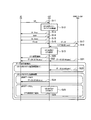
図11は、本実施形態に係る動作シーケンス図である。図11の初期状態として、eNB200は、全UE100に共通のDTXパターンで間欠送信(DTX)を行っている。ここでは、QoSに基づいてDTXパターンを変更する一例を説明する。
(3) Operation Sequence FIG. 11 is an operation sequence diagram according to the present embodiment. As an initial state of FIG. 11, the
図11に示すように、ステップS11において、UE100は、無線リソースの割当を要求するSR(Scheduling Request)をeNB200に送信する。SRは通信要求に相当する。
As illustrated in FIG. 11, in step S11, the
ステップS12において、eNB200は、UE100向けにタイマ(T100)を起動する。このタイマ(T100)は、SR受信に対して、その後の処理の途中で、送信停止状態に入らないようにするために設定したタイマです。具体的には、そのタイマ(T100)中に、S20までが終わることを想定している。
In step S12, the
ステップS13において、eNB200は、上りリンクの割当無線リソースを示すUL GrantをUE100に送信する。
In step S13, the
ステップS14において、UE100は、上りリンクの割当無線リソースを使用して、UE100のバッファ蓄積量を示すBSR(Buffer Status Report)をeNB200に送信する。
In step S14, the
ステップS15において、eNB200は、BSRが示すバッファ蓄積量に基づいて、上りリンクの割当無線リソースを示すUL GrantをUE100に送信する。 In step S15, eNB200 transmits UL Grant which shows the allocated radio | wireless resource of an uplink to UE100 based on the buffer storage amount which BSR shows.
ステップS16において、UE100は、上りリンクの割当無線リソースを使用して、上りリンクのデータをeNB200に送信する。
In step S16, the
ステップS17において、eNB200は、UE100からのデータをコアネットワーク(MME/S−GW300)に転送する。 In step S17, eNB200 transfers the data from UE100 to a core network (MME / S-GW300).
ステップS18において、コアネットワーク(MME/S−GW300)は、UE100のベアラに設定したQoSを示すQCIをeNB200に送信する。
In step S18, the core network (MME / S-GW 300) transmits the QCI indicating the QoS set in the bearer of the
ステップS19において、eNB200は、図10に示したテーブルを参照して、QCIに対応するDTXパターンを設定する。その結果、DTXパターンが変更される。
In step S19, the
ステップS20において、eNB200は、変更後のDTXパターンを示すパターン情報(DTX設定情報)をUE100に送信する。UE100−2は、そのパターン情報に基づいて変更後のDTXパターンを認識する。
In step S20, the
ステップS21において、コアネットワーク(MME/S−GW300)は、UE100へのデータをeNB200に送信する。
In step S21, the core network (MME / S-GW 300) transmits data to the
ステップS22において、eNB200は、コアネットワーク(MME/S−GW300)からのデータをUE100に転送する。eNB200は、DTXパターンに基づく起動時間(on Duration)内でUE100への送信を行う。UE100は、変更後のDTXパターンを認識しており、変更後のDTXパターンに合わせてeNB200からの受信を行う。
In step S22, eNB200 transfers the data from a core network (MME / S-GW300) to UE100. The
また、起動時間(on Duration)以外のタイミングでは、eNB200は、コアネットワーク(MME/S−GW300)からのデータを蓄積する(ステップS23)。起動時間(on Duration)においてUE100への送信データがある場合には、そのデータをUE100に送信する(ステップS24)。
Further, at a timing other than the activation time (on Duration), the
これに対し、起動時間(on Duration)においてUE100への送信データがない場合には、UE100のための一時的なDTXパターンを終了し(ステップS25)、そのDTXパターンの終了を示す終了通知をUE100に送信する(ステップS26)。尚、終了通知は、元のDTXパターン(共通のDTXパターン)を示す情報を含んでもよい。
On the other hand, if there is no transmission data to the
[変更例1]
上述した実施形態では、変更後のDTXパターン(一時的なDTXパターン)をRRCメッセージにより通知する一例を説明したが、他のメッセージを利用してもよい。
[Modification 1]
In the above-described embodiment, an example in which the changed DTX pattern (temporary DTX pattern) is notified by the RRC message has been described, but other messages may be used.
図12は、ランダムアクセス応答(RAR)を利用する場合のメッセージ構成例を示す図である。RARとは、UE100が初期接続時に送信するランダムアクセスプリアンブルに対する応答メッセージである。
FIG. 12 is a diagram illustrating an example of a message configuration when a random access response (RAR) is used. RAR is a response message to the random access preamble that
図12に示すように、本変更例に係るRARは、DTXパターン情報(Temporary DTX config.)を含む。DTXパターン情報(Temporary DTX config.)は、起動周期(dtx Cycle)を示す情報と、起動時間(on Duration)を示す情報と、オフセット値(dtx StartOffset)と、を含む。但し、これら全てのパラメータが必須という訳ではなく、例えば起動時間(on Duration)のみとし、RARの送信タイミングから起動時間(on Duration)の間は有効(eNB200の送信有り)としてもよい。
As shown in FIG. 12, the RAR according to this modification includes DTX pattern information (Temporary DTX config.). The DTX pattern information (Temporary DTX config.) Includes information indicating a start cycle (dtx cycle), information indicating a start time (on Duration), and an offset value (dtx StartOffset). However, all these parameters are not essential, and for example, only the activation time (on Duration) may be used, and may be valid during the activation time (on Duration) from the transmission timing of the RAR (the
[変更例2]
上述した実施形態では、間欠送信(DTX)を解除することについて特に触れなかった。しかしながら、eNB200は、セル内の複数のUE100からの通信要求の受信状況に基づいて、間欠送信(DTX)を解除して通常送信を開始してもよい。ある程度の量の通信が要求されるのであれば、サービス品質を向上させるために間欠送信(DTX)を解除することが望ましいためである。
[Modification 2]
In the above-described embodiment, no particular mention was made of canceling intermittent transmission (DTX). However, the
図13は、本変更例に係るeNB200の動作フロー図である。図13に示すように、eNB200は、間欠送信(DTX)を行っている場合(ステップS101;Yes)、ある期間において起動時間(on Duration)を集計する(ステップS102)。そして、集計した起動時間が閾値以上である場合(ステップS103;Yes)、間欠送信(DTX)を解除して通常状態に移行し(ステップS104)、間欠送信(DTX)の解除を自セル内の各UE100に通知する(ステップS105)。
FIG. 13 is an operation flowchart of the
[その他の実施形態]
上述した実施形態では、eNB200間の連携について特に触れなかった。しかしながら、eNB200は、DTXパターンをUE100に通知するだけでなく、隣接eNB200に通知してもよい。これにより、隣接eNB200が配下のUE100のモビリティ制御を適切に行うことができる。
[Other Embodiments]
In embodiment mentioned above, it did not touch in particular about cooperation between eNB200. However, the
また、上述した実施形態では、本発明をLTEシステムに適用するケースを主として説明したが、LTEシステムに限定されるものではなく、LTEシステム以外のシステムに本発明を適用してもよい。 In the above-described embodiment, the case where the present invention is applied to the LTE system is mainly described. However, the present invention is not limited to the LTE system, and the present invention may be applied to a system other than the LTE system.
E−UTRAN10、EPC20、UE100、アンテナ101、無線送受信機110、送信部111、受信部112、ユーザインターフェイス120、GNSS受信機130、バッテリ140、メモリ150、プロセッサ160、eNB200、アンテナ201、無線送受信機210、送信部211、受信部212、ネットワークインターフェイス220、メモリ230、プロセッサ240
E-UTRAN10, EPC20, UE100,
Claims (10)
無線信号を送信する送信部と、
前記送信部を間欠的に起動する間欠送信を行う制御部と、
前記セル内のユーザ端末からの通信要求を受信する受信部と、
を備え、
前記制御部は、前記間欠送信を行っている場合に、前記通信要求の受信に応じて前記送信部の起動パターンを一時的に変更し、変更後の前記起動パターンを示すパターン情報を前記ユーザ端末に通知することを特徴とする基地局。 A base station managing a cell,
A transmitter that transmits a radio signal;
A control unit that performs intermittent transmission for intermittently starting the transmission unit;
A receiving unit for receiving a communication request from a user terminal in the cell;
With
The control unit, when performing the intermittent transmission, temporarily changes the activation pattern of the transmission unit in response to reception of the communication request, and displays the pattern information indicating the changed activation pattern in the user terminal Base station characterized by notifying to.
前記制御部は、前記通信要求の受信に応じて、前記第1の周期よりも短い第2の周期を有する前記起動パターンに変更することを特徴とする請求項1に記載の基地局。 The control unit activates the transmission unit in a first cycle in the intermittent transmission,
The base station according to claim 1, wherein the control unit changes to the activation pattern having a second period shorter than the first period in response to reception of the communication request.
前記基地局は、前記送信部を間欠的に起動する間欠送信を行っており、
前記ユーザ端末は、
前記送信部の起動パターンを一時的に変更するように、前記基地局に対して通信要求を行う制御部と、
変更後の前記起動パターンを示すパターン情報を前記基地局から通知されると、前記パターン情報に基づいて前記基地局からの受信を行う受信部と、
を備えることを特徴とするユーザ端末。 A user terminal residing in a cell of a base station having a transmitter for transmitting a radio signal,
The base station performs intermittent transmission that intermittently activates the transmission unit,
The user terminal is
A control unit that makes a communication request to the base station so as to temporarily change a startup pattern of the transmission unit;
When pattern information indicating the activation pattern after the change is notified from the base station, a receiving unit that performs reception from the base station based on the pattern information;
A user terminal comprising:
前記基地局が、自セル内のユーザ端末からの通信要求を受信するステップと、
前記基地局が、前記通信要求の受信に応じて前記送信部の起動パターンを一時的に変更するステップと、
前記基地局が、変更後の前記起動パターンを示すパターン情報を前記ユーザ端末に通知するステップと、
を含むことを特徴とする通信制御方法。 A base station having a transmission unit for transmitting a radio signal performs intermittent transmission for intermittently starting the transmission unit;
The base station receiving a communication request from a user terminal in its own cell;
The base station temporarily changing the activation pattern of the transmitter in response to receiving the communication request;
The base station notifying the user terminal of pattern information indicating the activation pattern after the change;
The communication control method characterized by including.
Priority Applications (4)
| Application Number | Priority Date | Filing Date | Title |
|---|---|---|---|
| JP2013080001A JP2014204345A (en) | 2013-04-05 | 2013-04-05 | Base station, user terminal and communication control method |
| PCT/JP2014/059831 WO2014163139A1 (en) | 2013-04-05 | 2014-04-03 | Base station, user terminal, and communication control method |
| EP14778666.9A EP2983417A4 (en) | 2013-04-05 | 2014-04-03 | Base station, user terminal, and communication control method |
| US14/781,528 US20160044739A1 (en) | 2013-04-05 | 2014-04-03 | Base station, user terminal, and communication control method |
Applications Claiming Priority (1)
| Application Number | Priority Date | Filing Date | Title |
|---|---|---|---|
| JP2013080001A JP2014204345A (en) | 2013-04-05 | 2013-04-05 | Base station, user terminal and communication control method |
Publications (2)
| Publication Number | Publication Date |
|---|---|
| JP2014204345A true JP2014204345A (en) | 2014-10-27 |
| JP2014204345A5 JP2014204345A5 (en) | 2015-11-26 |
Family
ID=51658430
Family Applications (1)
| Application Number | Title | Priority Date | Filing Date |
|---|---|---|---|
| JP2013080001A Pending JP2014204345A (en) | 2013-04-05 | 2013-04-05 | Base station, user terminal and communication control method |
Country Status (4)
| Country | Link |
|---|---|
| US (1) | US20160044739A1 (en) |
| EP (1) | EP2983417A4 (en) |
| JP (1) | JP2014204345A (en) |
| WO (1) | WO2014163139A1 (en) |
Families Citing this family (2)
| Publication number | Priority date | Publication date | Assignee | Title |
|---|---|---|---|---|
| WO2020015431A1 (en) * | 2018-07-16 | 2020-01-23 | Huawei Technologies Co., Ltd. | Apparatus and methods of scheduling for low power consumption |
| CN116939779A (en) * | 2022-03-30 | 2023-10-24 | 大唐移动通信设备有限公司 | DTX transmission method, network node, network device and storage medium |
Citations (6)
| Publication number | Priority date | Publication date | Assignee | Title |
|---|---|---|---|---|
| JP2010508704A (en) * | 2006-10-27 | 2010-03-18 | インターデイジタル テクノロジー コーポレーション | Method and apparatus for enhancing discontinuous reception in a wireless system |
| JP2010521076A (en) * | 2007-03-09 | 2010-06-17 | 日本電気株式会社 | Discontinuous reception / transmission for mobile communication systems |
| JP2010521826A (en) * | 2007-03-12 | 2010-06-24 | シャープ株式会社 | Explicit layer 2 signaling for intermittent reception |
| WO2010146673A1 (en) * | 2009-06-17 | 2010-12-23 | 富士通株式会社 | Communication device, communication system, and communication method |
| WO2011096860A1 (en) * | 2010-02-04 | 2011-08-11 | Telefonaktiebolaget L M Ericsson (Publ) | Prioritization of energy over system throughput in a wireless communications system |
| JP2011250255A (en) * | 2010-05-28 | 2011-12-08 | Ntt Docomo Inc | Radio communication system and intermittent transmission method |
Family Cites Families (14)
| Publication number | Priority date | Publication date | Assignee | Title |
|---|---|---|---|---|
| US7110785B1 (en) * | 1999-12-03 | 2006-09-19 | Nortel Networks Limited | Performing power control in a mobile communications system |
| US6975868B2 (en) * | 2001-02-21 | 2005-12-13 | Qualcomm Incorporated | Method and apparatus for IS-95B reverse link supplemental code channel frame validation and fundamental code channel rate decision improvement |
| GB2382746B (en) * | 2001-11-20 | 2005-12-14 | Ericsson Telefon Ab L M | Establishing radio communication channels |
| WO2007144956A1 (en) * | 2006-06-16 | 2007-12-21 | Mitsubishi Electric Corporation | Mobile communication system and mobile terminal |
| FI20060666A0 (en) * | 2006-07-07 | 2006-07-07 | Nokia Corp | Procedures and systems for increasing the functionality of discontinuous transmission |
| AU2007288284B2 (en) * | 2006-08-21 | 2010-11-11 | Interdigital Technology Corporation | Method and apparatus for dynamically allocating HARQ processes in the uplink |
| EP2123095B1 (en) * | 2006-12-01 | 2010-06-30 | Interdigital Technology Corporation | Method and apparatus for controlling discontinuous transmission and reception |
| US10484946B2 (en) * | 2007-01-12 | 2019-11-19 | Electronics And Telecommunications Research Institute | Method of reporting measurement information in packet based on cellular system |
| US8184599B2 (en) * | 2008-06-23 | 2012-05-22 | Qualcomm Incorporated | Management of UE operation in a multi-carrier communication system |
| KR20120048044A (en) * | 2008-11-25 | 2012-05-14 | 인터디지탈 패튼 홀딩스, 인크 | Method and apparatus for utilizing a plurality of uplink carriers and a plurality of downlink carriers |
| US8462736B2 (en) * | 2009-06-19 | 2013-06-11 | Telefonaktiebolaget L M Ericsson (Publ) | Telecommunications method and apparatus for facilitating positioning measurements |
| US8737994B2 (en) * | 2010-11-05 | 2014-05-27 | Qualcomm Incorporated | Discontinuous transmission in femtocells |
| JP2013080001A (en) | 2011-09-30 | 2013-05-02 | Fujifilm Corp | Lens device and imaging device |
| US9026140B2 (en) * | 2012-10-12 | 2015-05-05 | Telefonaktiebolaget L M Ericsson (Publ) | Second node, positioning node and methods therein |
-
2013
- 2013-04-05 JP JP2013080001A patent/JP2014204345A/en active Pending
-
2014
- 2014-04-03 WO PCT/JP2014/059831 patent/WO2014163139A1/en active Application Filing
- 2014-04-03 EP EP14778666.9A patent/EP2983417A4/en not_active Withdrawn
- 2014-04-03 US US14/781,528 patent/US20160044739A1/en not_active Abandoned
Patent Citations (6)
| Publication number | Priority date | Publication date | Assignee | Title |
|---|---|---|---|---|
| JP2010508704A (en) * | 2006-10-27 | 2010-03-18 | インターデイジタル テクノロジー コーポレーション | Method and apparatus for enhancing discontinuous reception in a wireless system |
| JP2010521076A (en) * | 2007-03-09 | 2010-06-17 | 日本電気株式会社 | Discontinuous reception / transmission for mobile communication systems |
| JP2010521826A (en) * | 2007-03-12 | 2010-06-24 | シャープ株式会社 | Explicit layer 2 signaling for intermittent reception |
| WO2010146673A1 (en) * | 2009-06-17 | 2010-12-23 | 富士通株式会社 | Communication device, communication system, and communication method |
| WO2011096860A1 (en) * | 2010-02-04 | 2011-08-11 | Telefonaktiebolaget L M Ericsson (Publ) | Prioritization of energy over system throughput in a wireless communications system |
| JP2011250255A (en) * | 2010-05-28 | 2011-12-08 | Ntt Docomo Inc | Radio communication system and intermittent transmission method |
Also Published As
| Publication number | Publication date |
|---|---|
| EP2983417A1 (en) | 2016-02-10 |
| US20160044739A1 (en) | 2016-02-11 |
| WO2014163139A1 (en) | 2014-10-09 |
| EP2983417A4 (en) | 2016-11-02 |
Similar Documents
| Publication | Publication Date | Title |
|---|---|---|
| JP6295316B2 (en) | Base station and processor | |
| WO2014017476A1 (en) | Mobile communication system, base station, user device and processor | |
| WO2014069223A1 (en) | Mobile communication system, user terminal, base station, processor, and communication control method | |
| JP6125939B2 (en) | User terminal and processor | |
| WO2014050557A1 (en) | Mobile communication system, base station, and user terminal | |
| WO2015170766A1 (en) | User terminal and processor | |
| US10021039B2 (en) | Mobile communication system and user terminal | |
| WO2014163138A1 (en) | Base station | |
| US20160194986A1 (en) | Network device and communication control method | |
| JP6140323B2 (en) | Mobile communication system, base station and method | |
| WO2014163139A1 (en) | Base station, user terminal, and communication control method | |
| JP6298442B2 (en) | Base station and processor | |
| WO2014192629A1 (en) | User terminal, base station, and processor | |
| US10149243B2 (en) | Mobile communication system, base station, and user terminal | |
| JP6200078B2 (en) | User terminal, processor and method | |
| JP6034956B2 (en) | Mobile communication system, base station and user terminal | |
| JP6140014B2 (en) | User terminal, base station, and processor | |
| WO2014157397A1 (en) | Communication control method, user terminal, and base station | |
| WO2016148221A1 (en) | Communication apparatus and communication method |
Legal Events
| Date | Code | Title | Description |
|---|---|---|---|
| A521 | Request for written amendment filed |
Free format text: JAPANESE INTERMEDIATE CODE: A523 Effective date: 20151008 |
|
| A621 | Written request for application examination |
Free format text: JAPANESE INTERMEDIATE CODE: A621 Effective date: 20151215 |
|
| A131 | Notification of reasons for refusal |
Free format text: JAPANESE INTERMEDIATE CODE: A131 Effective date: 20170214 |
|
| A521 | Request for written amendment filed |
Free format text: JAPANESE INTERMEDIATE CODE: A523 Effective date: 20170414 |
|
| A131 | Notification of reasons for refusal |
Free format text: JAPANESE INTERMEDIATE CODE: A131 Effective date: 20171031 |
|
| A02 | Decision of refusal |
Free format text: JAPANESE INTERMEDIATE CODE: A02 Effective date: 20180508 |