EP4060865A1 - Wireless charging system, wireless charging method, and electric vehicle - Google Patents
Wireless charging system, wireless charging method, and electric vehicle Download PDFInfo
- Publication number
- EP4060865A1 EP4060865A1 EP21816667.6A EP21816667A EP4060865A1 EP 4060865 A1 EP4060865 A1 EP 4060865A1 EP 21816667 A EP21816667 A EP 21816667A EP 4060865 A1 EP4060865 A1 EP 4060865A1
- Authority
- EP
- European Patent Office
- Prior art keywords
- power
- auxiliary
- main
- battery
- voltage
- Prior art date
- Legal status (The legal status is an assumption and is not a legal conclusion. Google has not performed a legal analysis and makes no representation as to the accuracy of the status listed.)
- Pending
Links
Images


Classifications
-
- B—PERFORMING OPERATIONS; TRANSPORTING
- B60—VEHICLES IN GENERAL
- B60L—PROPULSION OF ELECTRICALLY-PROPELLED VEHICLES; SUPPLYING ELECTRIC POWER FOR AUXILIARY EQUIPMENT OF ELECTRICALLY-PROPELLED VEHICLES; ELECTRODYNAMIC BRAKE SYSTEMS FOR VEHICLES IN GENERAL; MAGNETIC SUSPENSION OR LEVITATION FOR VEHICLES; MONITORING OPERATING VARIABLES OF ELECTRICALLY-PROPELLED VEHICLES; ELECTRIC SAFETY DEVICES FOR ELECTRICALLY-PROPELLED VEHICLES
- B60L53/00—Methods of charging batteries, specially adapted for electric vehicles; Charging stations or on-board charging equipment therefor; Exchange of energy storage elements in electric vehicles
- B60L53/10—Methods of charging batteries, specially adapted for electric vehicles; Charging stations or on-board charging equipment therefor; Exchange of energy storage elements in electric vehicles characterised by the energy transfer between the charging station and the vehicle
- B60L53/12—Inductive energy transfer
-
- B—PERFORMING OPERATIONS; TRANSPORTING
- B60—VEHICLES IN GENERAL
- B60L—PROPULSION OF ELECTRICALLY-PROPELLED VEHICLES; SUPPLYING ELECTRIC POWER FOR AUXILIARY EQUIPMENT OF ELECTRICALLY-PROPELLED VEHICLES; ELECTRODYNAMIC BRAKE SYSTEMS FOR VEHICLES IN GENERAL; MAGNETIC SUSPENSION OR LEVITATION FOR VEHICLES; MONITORING OPERATING VARIABLES OF ELECTRICALLY-PROPELLED VEHICLES; ELECTRIC SAFETY DEVICES FOR ELECTRICALLY-PROPELLED VEHICLES
- B60L53/00—Methods of charging batteries, specially adapted for electric vehicles; Charging stations or on-board charging equipment therefor; Exchange of energy storage elements in electric vehicles
- B60L53/20—Methods of charging batteries, specially adapted for electric vehicles; Charging stations or on-board charging equipment therefor; Exchange of energy storage elements in electric vehicles characterised by converters located in the vehicle
-
- B—PERFORMING OPERATIONS; TRANSPORTING
- B60—VEHICLES IN GENERAL
- B60L—PROPULSION OF ELECTRICALLY-PROPELLED VEHICLES; SUPPLYING ELECTRIC POWER FOR AUXILIARY EQUIPMENT OF ELECTRICALLY-PROPELLED VEHICLES; ELECTRODYNAMIC BRAKE SYSTEMS FOR VEHICLES IN GENERAL; MAGNETIC SUSPENSION OR LEVITATION FOR VEHICLES; MONITORING OPERATING VARIABLES OF ELECTRICALLY-PROPELLED VEHICLES; ELECTRIC SAFETY DEVICES FOR ELECTRICALLY-PROPELLED VEHICLES
- B60L58/00—Methods or circuit arrangements for monitoring or controlling batteries or fuel cells, specially adapted for electric vehicles
- B60L58/10—Methods or circuit arrangements for monitoring or controlling batteries or fuel cells, specially adapted for electric vehicles for monitoring or controlling batteries
- B60L58/18—Methods or circuit arrangements for monitoring or controlling batteries or fuel cells, specially adapted for electric vehicles for monitoring or controlling batteries of two or more battery modules
- B60L58/21—Methods or circuit arrangements for monitoring or controlling batteries or fuel cells, specially adapted for electric vehicles for monitoring or controlling batteries of two or more battery modules having the same nominal voltage
-
- H—ELECTRICITY
- H01—ELECTRIC ELEMENTS
- H01F—MAGNETS; INDUCTANCES; TRANSFORMERS; SELECTION OF MATERIALS FOR THEIR MAGNETIC PROPERTIES
- H01F3/00—Cores, Yokes, or armatures
- H01F3/10—Composite arrangements of magnetic circuits
- H01F3/14—Constrictions; Gaps, e.g. air-gaps
-
- H—ELECTRICITY
- H02—GENERATION; CONVERSION OR DISTRIBUTION OF ELECTRIC POWER
- H02J—ELECTRIC POWER NETWORKS; CIRCUIT ARRANGEMENTS OR SYSTEMS FOR SUPPLYING OR DISTRIBUTING ELECTRIC POWER; SYSTEMS FOR STORING ELECTRIC ENERGY
- H02J50/00—Circuit arrangements or systems for wireless supply or distribution of electric power
- H02J50/10—Circuit arrangements or systems for wireless supply or distribution of electric power using inductive coupling
- H02J50/12—Circuit arrangements or systems for wireless supply or distribution of electric power using inductive coupling of the resonant type
-
- H—ELECTRICITY
- H02—GENERATION; CONVERSION OR DISTRIBUTION OF ELECTRIC POWER
- H02J—ELECTRIC POWER NETWORKS; CIRCUIT ARRANGEMENTS OR SYSTEMS FOR SUPPLYING OR DISTRIBUTING ELECTRIC POWER; SYSTEMS FOR STORING ELECTRIC ENERGY
- H02J50/00—Circuit arrangements or systems for wireless supply or distribution of electric power
- H02J50/40—Circuit arrangements or systems for wireless supply or distribution of electric power using two or more transmitting or receiving devices
- H02J50/402—Circuit arrangements or systems for wireless supply or distribution of electric power using two or more transmitting or receiving devices the two or more transmitting or the two or more receiving devices being integrated in the same unit, e.g. power mats with several coils or antennas with several sub-antennas
-
- H—ELECTRICITY
- H02—GENERATION; CONVERSION OR DISTRIBUTION OF ELECTRIC POWER
- H02J—ELECTRIC POWER NETWORKS; CIRCUIT ARRANGEMENTS OR SYSTEMS FOR SUPPLYING OR DISTRIBUTING ELECTRIC POWER; SYSTEMS FOR STORING ELECTRIC ENERGY
- H02J7/00—Circuit arrangements for charging or discharging batteries or for supplying loads from batteries
- H02J7/50—Circuit arrangements for charging or discharging batteries or for supplying loads from batteries acting upon multiple batteries simultaneously or sequentially
- H02J7/52—Circuit arrangements for charging or discharging batteries or for supplying loads from batteries acting upon multiple batteries simultaneously or sequentially for charge balancing, e.g. equalisation of charge between batteries
- H02J7/56—Active balancing, e.g. using capacitor-based, inductor-based or DC-DC converters
-
- H—ELECTRICITY
- H02—GENERATION; CONVERSION OR DISTRIBUTION OF ELECTRIC POWER
- H02M—APPARATUS FOR CONVERSION BETWEEN AC AND AC, BETWEEN AC AND DC, OR BETWEEN DC AND DC, AND FOR USE WITH MAINS OR SIMILAR POWER SUPPLY SYSTEMS; CONVERSION OF DC OR AC INPUT POWER INTO SURGE OUTPUT POWER; CONTROL OR REGULATION THEREOF
- H02M3/00—Conversion of DC power input into DC power output
- H02M3/01—Resonant DC/DC converters
-
- H—ELECTRICITY
- H02—GENERATION; CONVERSION OR DISTRIBUTION OF ELECTRIC POWER
- H02M—APPARATUS FOR CONVERSION BETWEEN AC AND AC, BETWEEN AC AND DC, OR BETWEEN DC AND DC, AND FOR USE WITH MAINS OR SIMILAR POWER SUPPLY SYSTEMS; CONVERSION OF DC OR AC INPUT POWER INTO SURGE OUTPUT POWER; CONTROL OR REGULATION THEREOF
- H02M3/00—Conversion of DC power input into DC power output
- H02M3/22—Conversion of DC power input into DC power output with intermediate conversion into AC
- H02M3/24—Conversion of DC power input into DC power output with intermediate conversion into AC by static converters
- H02M3/28—Conversion of DC power input into DC power output with intermediate conversion into AC by static converters using discharge tubes with control electrode or semiconductor devices with control electrode to produce the intermediate AC
- H02M3/325—Conversion of DC power input into DC power output with intermediate conversion into AC by static converters using discharge tubes with control electrode or semiconductor devices with control electrode to produce the intermediate AC using devices of a triode or a transistor type requiring continuous application of a control signal
- H02M3/335—Conversion of DC power input into DC power output with intermediate conversion into AC by static converters using discharge tubes with control electrode or semiconductor devices with control electrode to produce the intermediate AC using devices of a triode or a transistor type requiring continuous application of a control signal using semiconductor devices only
- H02M3/33561—Conversion of DC power input into DC power output with intermediate conversion into AC by static converters using discharge tubes with control electrode or semiconductor devices with control electrode to produce the intermediate AC using devices of a triode or a transistor type requiring continuous application of a control signal using semiconductor devices only having more than one ouput with independent control
-
- B—PERFORMING OPERATIONS; TRANSPORTING
- B60—VEHICLES IN GENERAL
- B60L—PROPULSION OF ELECTRICALLY-PROPELLED VEHICLES; SUPPLYING ELECTRIC POWER FOR AUXILIARY EQUIPMENT OF ELECTRICALLY-PROPELLED VEHICLES; ELECTRODYNAMIC BRAKE SYSTEMS FOR VEHICLES IN GENERAL; MAGNETIC SUSPENSION OR LEVITATION FOR VEHICLES; MONITORING OPERATING VARIABLES OF ELECTRICALLY-PROPELLED VEHICLES; ELECTRIC SAFETY DEVICES FOR ELECTRICALLY-PROPELLED VEHICLES
- B60L2210/00—Converter types
- B60L2210/30—AC to DC converters
-
- B—PERFORMING OPERATIONS; TRANSPORTING
- B60—VEHICLES IN GENERAL
- B60Y—INDEXING SCHEME RELATING TO ASPECTS CROSS-CUTTING VEHICLE TECHNOLOGY
- B60Y2200/00—Type of vehicle
- B60Y2200/90—Vehicles comprising electric prime movers
- B60Y2200/91—Electric vehicles
-
- H—ELECTRICITY
- H01—ELECTRIC ELEMENTS
- H01F—MAGNETS; INDUCTANCES; TRANSFORMERS; SELECTION OF MATERIALS FOR THEIR MAGNETIC PROPERTIES
- H01F5/00—Coils
- H01F5/02—Coils wound on non-magnetic supports, e.g. formers
- H01F2005/027—Coils wound on non-magnetic supports, e.g. formers wound on formers for receiving several coils with perpendicular winding axes, e.g. for antennae or inductive power transfer
-
- H—ELECTRICITY
- H02—GENERATION; CONVERSION OR DISTRIBUTION OF ELECTRIC POWER
- H02J—ELECTRIC POWER NETWORKS; CIRCUIT ARRANGEMENTS OR SYSTEMS FOR SUPPLYING OR DISTRIBUTING ELECTRIC POWER; SYSTEMS FOR STORING ELECTRIC ENERGY
- H02J2105/00—Networks for supplying or distributing electric power characterised by their spatial reach or by the load
- H02J2105/30—Networks for supplying or distributing electric power characterised by their spatial reach or by the load the load networks being external to vehicles, i.e. exchanging power with vehicles
-
- H—ELECTRICITY
- H02—GENERATION; CONVERSION OR DISTRIBUTION OF ELECTRIC POWER
- H02J—ELECTRIC POWER NETWORKS; CIRCUIT ARRANGEMENTS OR SYSTEMS FOR SUPPLYING OR DISTRIBUTING ELECTRIC POWER; SYSTEMS FOR STORING ELECTRIC ENERGY
- H02J2207/00—Details of circuit arrangements for charging or discharging batteries or supplying loads from batteries
- H02J2207/20—Charging or discharging characterised by the power electronics converter
-
- Y—GENERAL TAGGING OF NEW TECHNOLOGICAL DEVELOPMENTS; GENERAL TAGGING OF CROSS-SECTIONAL TECHNOLOGIES SPANNING OVER SEVERAL SECTIONS OF THE IPC; TECHNICAL SUBJECTS COVERED BY FORMER USPC CROSS-REFERENCE ART COLLECTIONS [XRACs] AND DIGESTS
- Y02—TECHNOLOGIES OR APPLICATIONS FOR MITIGATION OR ADAPTATION AGAINST CLIMATE CHANGE
- Y02T—CLIMATE CHANGE MITIGATION TECHNOLOGIES RELATED TO TRANSPORTATION
- Y02T10/00—Road transport of goods or passengers
- Y02T10/60—Other road transportation technologies with climate change mitigation effect
- Y02T10/70—Energy storage systems for electromobility, e.g. batteries
-
- Y—GENERAL TAGGING OF NEW TECHNOLOGICAL DEVELOPMENTS; GENERAL TAGGING OF CROSS-SECTIONAL TECHNOLOGIES SPANNING OVER SEVERAL SECTIONS OF THE IPC; TECHNICAL SUBJECTS COVERED BY FORMER USPC CROSS-REFERENCE ART COLLECTIONS [XRACs] AND DIGESTS
- Y02—TECHNOLOGIES OR APPLICATIONS FOR MITIGATION OR ADAPTATION AGAINST CLIMATE CHANGE
- Y02T—CLIMATE CHANGE MITIGATION TECHNOLOGIES RELATED TO TRANSPORTATION
- Y02T10/00—Road transport of goods or passengers
- Y02T10/60—Other road transportation technologies with climate change mitigation effect
- Y02T10/7072—Electromobility specific charging systems or methods for batteries, ultracapacitors, supercapacitors or double-layer capacitors
-
- Y—GENERAL TAGGING OF NEW TECHNOLOGICAL DEVELOPMENTS; GENERAL TAGGING OF CROSS-SECTIONAL TECHNOLOGIES SPANNING OVER SEVERAL SECTIONS OF THE IPC; TECHNICAL SUBJECTS COVERED BY FORMER USPC CROSS-REFERENCE ART COLLECTIONS [XRACs] AND DIGESTS
- Y02—TECHNOLOGIES OR APPLICATIONS FOR MITIGATION OR ADAPTATION AGAINST CLIMATE CHANGE
- Y02T—CLIMATE CHANGE MITIGATION TECHNOLOGIES RELATED TO TRANSPORTATION
- Y02T10/00—Road transport of goods or passengers
- Y02T10/60—Other road transportation technologies with climate change mitigation effect
- Y02T10/72—Electric energy management in electromobility
-
- Y—GENERAL TAGGING OF NEW TECHNOLOGICAL DEVELOPMENTS; GENERAL TAGGING OF CROSS-SECTIONAL TECHNOLOGIES SPANNING OVER SEVERAL SECTIONS OF THE IPC; TECHNICAL SUBJECTS COVERED BY FORMER USPC CROSS-REFERENCE ART COLLECTIONS [XRACs] AND DIGESTS
- Y02—TECHNOLOGIES OR APPLICATIONS FOR MITIGATION OR ADAPTATION AGAINST CLIMATE CHANGE
- Y02T—CLIMATE CHANGE MITIGATION TECHNOLOGIES RELATED TO TRANSPORTATION
- Y02T90/00—Enabling technologies or technologies with a potential or indirect contribution to GHG emissions mitigation
- Y02T90/10—Technologies relating to charging of electric vehicles
- Y02T90/12—Electric charging stations
-
- Y—GENERAL TAGGING OF NEW TECHNOLOGICAL DEVELOPMENTS; GENERAL TAGGING OF CROSS-SECTIONAL TECHNOLOGIES SPANNING OVER SEVERAL SECTIONS OF THE IPC; TECHNICAL SUBJECTS COVERED BY FORMER USPC CROSS-REFERENCE ART COLLECTIONS [XRACs] AND DIGESTS
- Y02—TECHNOLOGIES OR APPLICATIONS FOR MITIGATION OR ADAPTATION AGAINST CLIMATE CHANGE
- Y02T—CLIMATE CHANGE MITIGATION TECHNOLOGIES RELATED TO TRANSPORTATION
- Y02T90/00—Enabling technologies or technologies with a potential or indirect contribution to GHG emissions mitigation
- Y02T90/10—Technologies relating to charging of electric vehicles
- Y02T90/14—Plug-in electric vehicles
-
- Y—GENERAL TAGGING OF NEW TECHNOLOGICAL DEVELOPMENTS; GENERAL TAGGING OF CROSS-SECTIONAL TECHNOLOGIES SPANNING OVER SEVERAL SECTIONS OF THE IPC; TECHNICAL SUBJECTS COVERED BY FORMER USPC CROSS-REFERENCE ART COLLECTIONS [XRACs] AND DIGESTS
- Y02—TECHNOLOGIES OR APPLICATIONS FOR MITIGATION OR ADAPTATION AGAINST CLIMATE CHANGE
- Y02T—CLIMATE CHANGE MITIGATION TECHNOLOGIES RELATED TO TRANSPORTATION
- Y02T90/00—Enabling technologies or technologies with a potential or indirect contribution to GHG emissions mitigation
- Y02T90/10—Technologies relating to charging of electric vehicles
- Y02T90/16—Information or communication technologies improving the operation of electric vehicles
Definitions
- the present disclosure relates to technology for wirelessly charging a battery using magnetic resonance.
- a battery pack includes a plurality of batteries connected in series. To wirelessly charge the plurality of batteries individually, a power receiving device needs to be provided to each battery.
- a plurality of power transmitting devices is installed in a wireless charging system.
- a wireless charging system For example, to individually charge 10 batteries, 10 power receiving devices and 10 power transmitting devices are required.
- a wireless communication circuit of the power receiving device transmits the battery information to a wireless communication circuit of the power transmitting device, and the power transmitting device controls the charge of each battery based on the received battery information.
- the wireless charging system including the plurality of power receiving devices and the plurality of power transmitting devices, each equipped with the wireless communication circuit, and the volume and weight of the entire wireless charging system increase. Additionally, when a communication error occurs in the wireless communication circuit provided in the power receiving device and/or the power transmitting device, it is impossible to transmit and receive the battery information.
- the present disclosure is designed to solve the above-described problem, and therefore the present disclosure is directed to providing a wireless charging system, a wireless charging method and an electric vehicle, in which a single power transmitting device wirelessly transmits an alternating charging current individually to a plurality of power receiving devices using magnetic resonance.
- the present disclosure is further directed to providing a wireless charging system, a wireless charging method and an electric vehicle, in which battery information of a battery connected to a power receiving device is acquired (estimated) based on the voltage and current of alternating current (AC) power wirelessly transmitted to the power receiving device without wireless communication of a power transmitting device with the power receiving device.
- a wireless charging system a wireless charging method and an electric vehicle, in which battery information of a battery connected to a power receiving device is acquired (estimated) based on the voltage and current of alternating current (AC) power wirelessly transmitted to the power receiving device without wireless communication of a power transmitting device with the power receiving device.
- AC alternating current
- a wireless charging system includes a first power receiving device connected in parallel to a first battery and including a first sub resonant circuit having a first resonant frequency, a second power receiving device connected in parallel to a second battery and including a second sub resonant circuit having a second resonant frequency, and a power transmitting device including a main resonant circuit.
- the power transmitting device is configured to determine, in a preliminary charging mode, a charging order between the first battery and the second battery.
- the power transmitting device is configured to wirelessly transmit, in a normal charging mode, first alternating current (AC) power having the first resonant frequency to the first sub resonant circuit through the main resonant circuit when the first battery is selected according to the charging order.
- the power transmitting device is configured to wirelessly transmit, in the normal charging mode, second AC power having the second resonant frequency to the second sub resonant circuit through the main resonant circuit when the second battery is selected according to the charging order.
- the first sub resonant circuit may include a first sub coil and a first sub capacitor connected in series.
- the second sub resonant circuit may include a second sub coil and a second sub capacitor connected in series.
- the first power receiving device may further include a first rectification circuit configured to convert the first AC power received by the first sub resonant circuit to first direct current (DC) power, and supply the first DC power to the first battery.
- a first rectification circuit configured to convert the first AC power received by the first sub resonant circuit to first direct current (DC) power, and supply the first DC power to the first battery.
- the second power receiving device may further include a second rectification circuit configured to convert the second AC power received by the second sub resonant circuit to second DC power, and supply the second DC power to the second battery.
- a second rectification circuit configured to convert the second AC power received by the second sub resonant circuit to second DC power, and supply the second DC power to the second battery.
- the power transmitting device may be configured to wirelessly transmit, in the preliminary charging mode, the first AC power during a first main time.
- the power transmitting device may be configured to record first main sensing information indicating AC voltage and AC current of the first AC power.
- the power transmitting device may be configured to wirelessly transmit first auxiliary power having a first auxiliary frequency during a first auxiliary time.
- the power transmitting device may be configured to record first auxiliary sensing information indicating AC voltage and AC current of the first auxiliary power.
- the power transmitting device may be configured to determine a first DC voltage of the first battery based on the first main sensing information and the first auxiliary sensing information.
- the power transmitting device may be configured to wirelessly transmit the second AC power during a second main time.
- the power transmitting device may be configured to record second main sensing information indicating AC voltage and AC current of the second AC power.
- the power transmitting device may be configured to wirelessly transmit second auxiliary power having a second auxiliary frequency during a second auxiliary time.
- the power transmitting device may be configured to record second auxiliary sensing information indicating AC voltage and AC current of the second auxiliary power.
- the power transmitting device may be configured to determine a second DC voltage of the second battery based on the second main sensing information and the second auxiliary sensing information.
- the power transmitting device may be configured to determine the charging order between the first battery and the second battery based on the first DC voltage and the second DC voltage.
- the power transmitting device may further include a power generation circuit configured to selectively supply the main resonant circuit with the first AC power, the first auxiliary power, the second AC power and the second auxiliary power, a sensing circuit configured to sense AC voltage and AC current of the AC power supplied to the main resonant circuit, and a control circuit operably coupled to the main resonant circuit, the power generation circuit and the sensing circuit.
- a power generation circuit configured to selectively supply the main resonant circuit with the first AC power, the first auxiliary power, the second AC power and the second auxiliary power
- a sensing circuit configured to sense AC voltage and AC current of the AC power supplied to the main resonant circuit
- a control circuit operably coupled to the main resonant circuit, the power generation circuit and the sensing circuit.
- the main resonant circuit may include a main coil and a variable capacitor connected in series.
- the control circuit may be configured to adjust a capacitance of the variable capacitor to be equal to one of a first main capacitance, a first auxiliary capacitance, a second main capacitance and a second auxiliary capacitance that are different from one another.
- the first resonant frequency may be equal to a resonant frequency by a main inductance of the main coil and the first main capacitance.
- the first auxiliary frequency may be equal to a resonant frequency by the main inductance and the first auxiliary capacitance.
- the second resonant frequency may be equal to a resonant frequency by the main inductance and the second main capacitance.
- the second auxiliary frequency may be equal to a resonant frequency by the main inductance and the second auxiliary capacitance.
- An electric vehicle may include the wireless charging system.
- a wireless charging method is for a first battery connected in parallel to a first sub resonant circuit having a first resonant frequency and a second battery connected in parallel to a second sub resonant circuit having a second resonant frequency.
- the wireless charging method includes determining, in a preliminary charging mode, a charging order between the first battery and the second battery, wirelessly transmitting, in a normal charging mode, first AC power having the first resonant frequency to the first sub resonant circuit when the first battery is selected according to the charging order, and wirelessly transmitting, in the normal charging mode, second AC power having the second resonant frequency to the second sub resonant circuit when the second battery is selected according to the charging order.
- Determining the charging order may include wirelessly transmitting the first AC power during a first main time, recording first main sensing information indicating AC voltage and AC current of the first AC power, wirelessly transmitting first auxiliary power having a first auxiliary frequency during a first auxiliary time, recording first auxiliary sensing information indicating AC voltage and AC current of the first auxiliary power, determining a first DC voltage of the first battery based on the first main sensing information and the first auxiliary sensing information, wirelessly transmitting the second AC power during a second main time, recording second main sensing information indicating AC voltage and AC current of the second AC power, wirelessly transmitting second auxiliary power having a second auxiliary frequency during a second auxiliary time, recording second auxiliary sensing information indicating AC voltage and AC current of the second auxiliary power, determining a second DC voltage of the second battery based on the second main sensing information and the second auxiliary sensing information, and determining the charging order between the first battery and the second battery between the first DC voltage and the second DC voltage.
- a single power transmitting device may wirelessly transmit an alternating charging current individually to the plurality of power receiving devices using magnetic resonance.
- FIG. 1 is a diagram exemplarily showing a configuration of an electric vehicle 1 according to an embodiment of the present disclosure
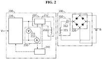
- FIG. 2 is a diagram exemplarily showing a configuration of a power transmitting device 200 and a power receiving device 300 of FIG. 1
- FIG. 3 is a diagram exemplarily showing a configuration of a variable capacitor 212 of FIG. 2 .
- the electric vehicle 1 includes a vehicle controller 2, a relay 10, an inverter 20, an electric motor 30, a battery group 40 and a wireless charging system 100.
- the vehicle controller 2 is configured to generate a key-on signal in response to a user's switching of an ignition button (not shown) provided in the electric vehicle 1 to an ON-position.
- the vehicle controller 2 is configured to generate a key-off signal in response to the user's switching of the ignition button to an OFF-position.
- the relay 10 is installed on a power line for the battery group 40.
- the on-off of the relay 10 may be controlled by the vehicle controller 2 and/or the wireless charging system 100. While the relay 10 is in an on-state, power may be transmitted from any one of the battery group 40 and the inverter from the other.
- the inverter 20 converts direct current (DC) power supplied from the battery group 40 to alternating current (AC) power and supplies it to the electric motor 30.
- the electric motor 30 converts the AC power from the inverter 20 to kinetic energy for the electric vehicle 1.
- the electric motor may be, for example, a single-phase induction motor or a 3-phase induction motor.
- the battery group 40 includes a plurality of batteries B 1 ⁇ B n connected in series. n is a natural number of 2 or greater.
- the battery B is not limited to a particular type, and includes any type of battery that can be charged and discharged repeatedly, such as, for example, a lithium ion battery.
- the wireless charging system 100 includes a power transmitting device 200 and a plurality of power receiving devices 300 1 ⁇ 300 n .
- the plurality of power receiving devices 300 1 ⁇ 300 n is connected in parallel to the plurality of batteries B 1 ⁇ B n in a one-to-one relationship. That is, when i is a natural number of 1 ⁇ n, the power receiving device 300i is connected in parallel to the battery B i .
- the i th power receiving device 300i is configured to wirelessly receive AC power having frequency in an i th range wirelessly transmitted from the power transmitting device 200 through magnetic resonance.
- the i th power receiving device 300i charges the i th battery B i using the received AC power.
- the power transmitting device 200 is configured to wirelessly transmit the AC power individually to the plurality of power receiving devices 300 1 ⁇ 300 n . That is, to charge the i th battery B i , the power transmitting device 200 may select the i th resonant frequency from first to n th resonant frequencies, and generate AC power having the selected i th resonant frequency.
- the i th power receiving device 300i has an i th sub resonant circuit 310i.
- the i th sub resonant circuit 310i has the i th resonant frequency. That is, when the frequency of the AC power transmitted by the power transmitting device 200 matches the i th resonant frequency, the i th sub resonant circuit 310i is at the maximum magnetic resonance. As a difference between the frequency of the AC power transmitted by the power transmitting device 200 and the i th resonant frequency increases, the magnetic resonance of the i th sub resonant circuit 310i gradually reduces.
- the i th sub resonant circuit 310i includes an i th sub coil 311 i and an i th sub capacitor 312i connected in series.
- fi is the i th resonant frequency
- L S_i is the inductance of the i th sub coil 311 i
- C S_i is the capacitance of the i th sub capacitor 312i
- fi 1/ ⁇ 2 ⁇ (C S_i ⁇ L S_i ) 0.5 ⁇ .
- the i th power receiving device 300i may further include an i th rectification circuit 320i.
- the i th rectification circuit 320i may be a diode bridge circuit including 4 diodes.
- the i th rectification circuit 320i includes a pair of input terminals and a pair of output terminals. The pair of input terminals of the i th rectification circuit 320i are connected to a first terminal and a second terminal of the i th sub resonant circuit 310i respectively.
- the pair of output terminals of the i th rectification circuit 320i are connected to a first terminal (for example, a positive electrode terminal) and a second terminal (for example, a negative electrode terminal) of the i th battery B i , respectively.
- the power transmitting device 200 includes a main resonant circuit 210.
- the main resonant circuit 210 includes a main coil 211 and a variable capacitor 212 connected in series.
- a control circuit 240 is configured to adjust the capacitance of the variable capacitor 212 among first to n th main capacitance and first to n th auxiliary capacitance. That is, the capacitance of the variable capacitor 212 may be selected from the first to n th main capacitance and the first to n th auxiliary capacitance.
- the resonant frequency of the main resonant circuit 210 may be adjusted to match the frequency of the AC power supplied to the main resonant circuit 210. Accordingly, the AC power generated by the main resonant circuit 210 may be wirelessly received by at least one of the plurality of power receiving devices 300 1 ⁇ 300 n by magnetic resonance. For example, when the AC power of the i th resonant frequency is inputted to the main resonant circuit 210, the resonant frequency of the main resonant circuit 210 may be adjusted to match the i th resonant frequency. Accordingly, the AC power having the i th resonant frequency may be transmitted to the i th sub resonant circuit 310i through the main resonant circuit 210.
- the power transmitting device 200 may further include a power generation circuit 220.
- the power generation circuit 220 is configured to convert the input DC power V IN supplied from a DC voltage source (for example, a lead acid battery) provided in the electric vehicle 1 or a charging station to AC power having a desired frequency.
- a DC voltage source for example, a lead acid battery
- Well-known single-phase full-bridge inverters and/or oscillators may be used as the power generation circuit 220.
- the frequency of the AC power generated by the power generation circuit 220 may be selected from first to n th resonant frequencies and first to n th auxiliary frequencies.
- the AC power having the selected frequency may be wirelessly transmitted as a charging signal to at least one of the plurality of power receiving devices 300 1 ⁇ 300 n through the main resonant circuit 210.
- the power transmitting device 200 may further include a sensing circuit 230.
- the sensing circuit 230 includes a voltage sensor 231 and a current sensor 232.
- the sensing circuit 230 is configured to sense the AC voltage and AC current of the AC power supplied to the main resonant circuit 210, and transmit a signal indicating the sensed information to the control circuit 240.
- the power transmitting device 200 may further include the control circuit 240.
- the control circuit 240 is operably coupled to at least one of the main resonant circuit 210, the power generation circuit 220 or the sensing circuit 230.
- the operably coupled refers to connection to enable signal transmission and reception in one or two directions.
- the control circuit 240 may be implemented, in hardware, using at least one of application specific integrated circuits (ASICs), digital signal processors (DSPs), digital signal processing devices (DSPDs), programmable logic devices (PLDs), field programmable gate arrays (FPGAs), microprocessors or electrical units for performing other functions.
- the control circuit 240 may include an embedded memory.
- the memory may include, for example, at least one type of storage medium of flash memory type, hard disk type, Solid State Disk (SSD) type, Silicon Disk Drive (SDD) type, multimedia card micro type, random access memory (RAM), static random access memory (SRAM), read-only memory (ROM), electrically erasable programmable read-only memory (EEPROM) or programmable read-only memory (PROM).
- the memory may store data and programs required for the calculation operation by the control circuit 240.
- the control circuit 240 may store data indicating the result of the calculation operation in the memory.
- the control circuit 240 may control the power generation circuit 220 and the main resonant circuit 210 to match the frequency of the AC power generated by the power generation circuit 220 to the frequency of the main resonant circuit 210. For example, when one of first to n th different resonant frequencies and first to n th different auxiliary frequencies is selected, the control circuit 240 may match each of the frequency of the AC power generated by the power generation circuit 220 and the resonant frequency of the main resonant circuit 210 to the selected frequency.
- the variable capacitor 212 includes a selection switch 213 and a capacitor circuit 214 connected in series.
- the capacitor circuit 214 may include first to n th main capacitors 215 1 ⁇ 215 n and first to n th auxiliary capacitors 216 1 ⁇ 216 n connected in parallel.
- the capacitance of the i th main capacitor 215i is referred to as 'i th main capacitance'
- the capacitance of the i th auxiliary capacitor 216i is referred to as 'i th auxiliary capacitance'.
- the frequency of the AC power wirelessly transmitted from the main resonant circuit 210 is 1/ ⁇ 2 ⁇ ⁇ (C M_i ⁇ L M ) 0.5 ⁇ , and is equal to the i th resonant frequency.
- the frequency of the AC power wirelessly transmitted from the main resonant circuit 210 is 1/ ⁇ 2 ⁇ ⁇ (C A_i ⁇ L M ) 0.5 ⁇ , and is equal to the i th auxiliary frequency.
- the i th auxiliary frequency may have the smallest difference with the i th resonant frequency among the first to n th resonant frequencies. For example, a difference between any two of the first to n th resonant frequencies may be larger than a predetermined value, and a difference between the i th auxiliary frequency and the i th resonant frequency may be less than a predetermined value. Accordingly, magnetic resonance by the i th auxiliary power is at the maximum in the i th sub resonant circuit 310i among the first to n th sub resonant circuits 310 1 ⁇ 310 n .
- the first to n th auxiliary capacitors 216 1 ⁇ 216 n may be used in a preliminary charging mode for determining a charging order between the plurality of batteries B 1 ⁇ B n .
- FIG. 4 is a diagram exemplarily showing an equivalent circuit of the power transmitting device 200 and the power receiving device 300 of FIG. 1 in phasor form.
- Vi denotes the voltage phasor indicating the AC voltage of the main resonant circuit 210
- I 1 denotes the current phasor indicating the AC current of the main resonant circuit 210
- Z 1 denotes the equivalent impedance of the main resonant circuit 210
- Z R denotes the combined impedance by the inductive coupling between the main coil 211 and the i th sub coil 311 i
- V2 denotes the voltage phasor indicating the AC voltage of the i th sub resonant circuit 310i
- I 2 denotes the current phasor indicating the AC current of the main resonant circuit 210
- Z 2 denotes the equivalent impedance of the i th sub resonant circuit 310i
- R L denotes the equivalent resistance of the i th rectification circuit 320 i and the i th the battery B i .
- Z 1 , Z 2 and Z R denotes the equivalent resistance of
- Ri equivalent resistance of the main resonant circuit 210
- L M inductance (main inductance) of the main coil 211
- Cv capacitance of the variable capacitor 212
- f (L M ⁇ C V ) 0.5
- Z 2 j ⁇ L S _ i + 1 / j 2 ⁇ fC S _ i + R 2
- L S_i inductance of i th sub coil 311 i
- C S_i capacitance of i th sub capacitor 312i
- R2 the equivalent resistance of i th sub resonant circuit 310i.
- Z R 2 ⁇ fM i 2 / Z 2 + R L
- Mi inductance between the main coil 211 and the i th sub coil 311 i .
- Vi, I 1 , V2 and I 2 satisfy the relationship of Equation 4 to Equation 6.
- R 1 , L M and Cv are values indicating the unique characteristics of the main resonant circuit 210 and are pre-stored in the control circuit 240.
- R 2 , L S_i and C S_i are values indicating the unique characteristics of the i th sub resonant circuit 310i and are pre-stored in the control circuit 240.
- f is a value selected from the first to n th resonant frequencies and the first to n th auxiliary frequencies, each frequency being preset. That is, among the parameters of Equation 4, only two parameters R L and Mi are unknown.
- each unknown may be determined (estimated) by acquiring two sensing information indicating V 1 and I 1 of Equation 4.
- the control circuit 240 may record V 1 and I 1 sensed by the sensing circuit 230 as the i th main sensing information when the i th resonant frequency is selected as f of Equation 4, and record V 1 and I 1 sensed by the sensing circuit 230 as the i th auxiliary sensing information when the i th auxiliary frequency is selected as f of Equation 4.
- the control circuit 240 may calculate R L and Mi based on the i th main sensing information, the i th auxiliary sensing information and Equation 4.
- the i th main sensing information indicates V 1 and I 1 of Equation 4 when f of Equation 4 is equal to the i th resonant frequency
- the i th auxiliary sensing information indicates V 1 and I 1 of Equation 4 when f of Equation 4 is equal to the i th auxiliary frequency.
- R L and Mi may be determined as the solutions of simultaneous equations obtained from Equation 4.
- the control circuit 240 may calculate I 2 of Equation 5 based on R L , Mi and I 1 .
- the control circuit 240 may calculate V2 of Equation 6 based on R L and I 2 . That is, the control circuit 240 may calculate (estimate) the amplitude and phase of each of the AC voltage and AC current of the i th sub resonant circuit 310i based on the amplitude and phase of each of the AC voltage and AC current of the main resonant circuit 210.
- the i th AC power received by the i th sub resonant circuit 310i is converted to the i th DC power through the i th rectification circuit 320i and supplied to the i th battery B i .
- the control circuit 240 may determine i th DC voltage which is a voltage across the i th battery to be equal to the voltage amplitude of V2 of Equation 6.
- the i th DC voltage corresponds to a state of charge (SOC) of the i th battery B i .
- the power transmitting device 200 may determine first to n th DC voltages by performing the above-described process once for each of the plurality of sub resonant circuits. Assume n ⁇ a>b>1.
- the a th DC voltage less than the b th DC voltage indicates that the SOC of the a th battery B a is less than the SOC of the b th battery B b .
- the a th DC voltage larger than the b th DC voltage indicates that the SOC of the a th battery B a is larger than the SOC of the b th battery Bb.
- the control circuit 240 may determine the charging order between the first to n th batteries B 1 ⁇ B n by arranging the first to n th DC voltages in order of magnitude.
- FIG. 5 is a flowchart exemplarily showing a wireless charging method according to a first embodiment of the present disclosure. The method of FIG. 5 may be performed to determine the charging order between the plurality of batteries B 1 ⁇ B n in the preliminary charging mode.
- step S500 the control circuit 240 of the power transmitting device 200 sets a first index k to be equal to 1.
- the power transmitting device 200 wirelessly transmits k th AC power during k th main time.
- the control circuit 240 sets the resonant frequency of the main resonant circuit 210 to be equal to the k th resonant frequency during the k th main time.
- the k th main time may be preset to be equal to or larger than 1/fk.
- the k th AC power is AC power having the k th resonant frequency.
- the first index is 1, the first AC power having the first resonant frequency is wirelessly transmitted by the main resonant circuit 210 during the first main time.
- step S520 the power transmitting device 200 records k th main sensing information.
- the k th main sensing information may include the amplitude of each of the AC voltage and AC current of the k th AC power wirelessly transmitted from the power transmitting device 200 in step S510.
- step S530 the power transmitting device 200 wirelessly transmits k th auxiliary power having k th auxiliary frequency during k th auxiliary time.
- the control circuit 240 sets the resonant frequency of the main resonant circuit 210 to be equal to the k th auxiliary frequency during the k th auxiliary time.
- the k th auxiliary time may be preset to be equal to or larger than 1/(k th auxiliary frequency).
- step S540 the power transmitting device 200 records k th auxiliary sensing information.
- the k th auxiliary sensing information may include the amplitude of each of the AC current voltage and AC current of the k th auxiliary power wirelessly transmitted from the power transmitting device 200 in step S530.
- step S550 the power transmitting device 200 determines k th DC voltage based on the k th main sensing information and the k th auxiliary sensing information (see Equations 4 to 6).
- step S560 the power transmitting device 200 determines whether the first index k is equal to a target index n.
- the target index n is the total number of batteries B included in the wireless charging system 100.
- step S562 the power transmitting device 200 increases the first index k by 1. After the step S562, the method of FIG. 5 may move to the step S510.
- the power transmitting device 200 determines a charging order between the first to n th batteries B 1 ⁇ B n based on the first to n th DC voltages.
- the control circuit 240 may arrange the first to n th DC voltages in an ascending order, and give higher charging orders to the batteries corresponding to lower DC voltages. For example, when the first DC voltage is less than the second DC voltage, the control circuit 240 gives a higher charging order than the second battery B 2 to the first battery B 1 so that the first battery B 1 has priority over the second battery B 2 , and in other cases, gives a higher charging order than the first battery B 1 to the second battery B 2 .
- the control circuit 240 may store a flag indicating the charging order of each of the first to n th batteries B 1 ⁇ B n in the memory.
- FIG. 6 is a flowchart exemplarily showing a wireless charging method according to a second embodiment of the present disclosure.
- the method of FIG. 6 may be performed to sequentially charge the plurality of batteries B 1 ⁇ B n in the normal charging mode according to the charging order determined through the method of FIG. 5 .
- step S600 the power transmitting device 200 sets a second index x to 1.
- the second index x indicates the charging order.
- step S610 the power transmitting device 200 selects the j th battery B j , one of the first to n th batteries B 1 ⁇ B n , as a target to be charged according to the x th charging order.
- the j th battery B j is assigned with the x th highest charging rank among the first to n th batteries B 1 ⁇ B n .
- step S620 the power transmitting device 200 wirelessly transmits j th AC power having j th resonant frequency associated with the battery B j selected in the step S610.
- the j th AC power having the j th resonant frequency is wirelessly transmitted. Accordingly, the j th AC power is wirelessly received by the j th sub resonant circuit.
- step S630 the power transmitting device 200 determines whether the charging of the j th battery B j is completed. Specifically, the control circuit 240 determines DC voltage of the j th battery B j at a predetermined time interval during the charge of the j th battery B j (see Equations 4 to 6), and when the DC voltage of the j th battery B j reaches a preset upper limit of voltage, determine that the charging is completed. When a value of the step S630 is "No", the step S630 may be repeated. When the value of the step S630 is "Yes", step S640 is performed.
- step S640 the power transmitting device 200 determines whether the second index x is equal to a target index n.
- the target index n is the total number of batteries B included in the wireless charging system 100.
- step S642 is performed.
- the value of the step S640 being "Yes” indicates that charging of all the first to n th batteries B 1 ⁇ B n is completed.
- step S642 the power transmitting device 200 increases the second index x by 1. After the step S642, the method of FIG. 6 may move to the step S610.
Landscapes
- Engineering & Computer Science (AREA)
- Power Engineering (AREA)
- Computer Networks & Wireless Communication (AREA)
- Transportation (AREA)
- Mechanical Engineering (AREA)
- Composite Materials (AREA)
- Chemical & Material Sciences (AREA)
- Sustainable Energy (AREA)
- Sustainable Development (AREA)
- Life Sciences & Earth Sciences (AREA)
- Charge And Discharge Circuits For Batteries Or The Like (AREA)
- Current-Collector Devices For Electrically Propelled Vehicles (AREA)
- Electric Propulsion And Braking For Vehicles (AREA)
Abstract
Description
- The present disclosure relates to technology for wirelessly charging a battery using magnetic resonance.
- The present application claims the benefit of
Korea patent Application No. 10-2020-0067106 filed on June 3, 2020 - Recently, there has been a rapid increase in the demand for portable electronic products such as laptop computers, video cameras and mobile phones, and with the extensive development of electric vehicles, accumulators for energy storage, robots and satellites, many studies are being made on high performance batteries that can be charged and discharged repeatedly.
- Currently, commercially available batteries include nickel-cadmium batteries, nickel-hydrogen batteries, nickel-zinc batteries, lithium batteries and the like, and among them, lithium batteries have little or no memory effect, and thus they are gaining more attention than nickel-based batteries for their advantages that recharging can be done whenever it is convenient, the self-discharge rate is very low and the energy density is high.
- In general, a battery pack includes a plurality of batteries connected in series. To wirelessly charge the plurality of batteries individually, a power receiving device needs to be provided to each battery.
- Conventionally, to wirelessly transmit alternating current (AC) charging power to a plurality of power receiving devices in a one-to-one relationship, a plurality of power transmitting devices is installed in a wireless charging system. For example, to individually charge 10 batteries, 10 power receiving devices and 10 power transmitting devices are required.
- Meanwhile, to effectively perform the wireless charge of the plurality of batteries, it is necessary to monitor battery information (for example, voltage, etc.) of each battery. To this end, a wireless communication circuit of the power receiving device transmits the battery information to a wireless communication circuit of the power transmitting device, and the power transmitting device controls the charge of each battery based on the received battery information.
- However, high costs are required to manufacture the wireless charging system including the plurality of power receiving devices and the plurality of power transmitting devices, each equipped with the wireless communication circuit, and the volume and weight of the entire wireless charging system increase. Additionally, when a communication error occurs in the wireless communication circuit provided in the power receiving device and/or the power transmitting device, it is impossible to transmit and receive the battery information.
- The present disclosure is designed to solve the above-described problem, and therefore the present disclosure is directed to providing a wireless charging system, a wireless charging method and an electric vehicle, in which a single power transmitting device wirelessly transmits an alternating charging current individually to a plurality of power receiving devices using magnetic resonance.
- The present disclosure is further directed to providing a wireless charging system, a wireless charging method and an electric vehicle, in which battery information of a battery connected to a power receiving device is acquired (estimated) based on the voltage and current of alternating current (AC) power wirelessly transmitted to the power receiving device without wireless communication of a power transmitting device with the power receiving device.
- These and other objects and advantages of the present disclosure may be understood by the following description and will be apparent from the embodiments of the present disclosure. In addition, it will be readily understood that the objects and advantages of the present disclosure may be realized by the means set forth in the appended claims and a combination thereof.
- A wireless charging system according to an aspect of the present disclosure includes a first power receiving device connected in parallel to a first battery and including a first sub resonant circuit having a first resonant frequency, a second power receiving device connected in parallel to a second battery and including a second sub resonant circuit having a second resonant frequency, and a power transmitting device including a main resonant circuit. The power transmitting device is configured to determine, in a preliminary charging mode, a charging order between the first battery and the second battery. The power transmitting device is configured to wirelessly transmit, in a normal charging mode, first alternating current (AC) power having the first resonant frequency to the first sub resonant circuit through the main resonant circuit when the first battery is selected according to the charging order. The power transmitting device is configured to wirelessly transmit, in the normal charging mode, second AC power having the second resonant frequency to the second sub resonant circuit through the main resonant circuit when the second battery is selected according to the charging order.
- The first sub resonant circuit may include a first sub coil and a first sub capacitor connected in series. The second sub resonant circuit may include a second sub coil and a second sub capacitor connected in series.
- The first power receiving device may further include a first rectification circuit configured to convert the first AC power received by the first sub resonant circuit to first direct current (DC) power, and supply the first DC power to the first battery.
- The second power receiving device may further include a second rectification circuit configured to convert the second AC power received by the second sub resonant circuit to second DC power, and supply the second DC power to the second battery.
- The power transmitting device may be configured to wirelessly transmit, in the preliminary charging mode, the first AC power during a first main time. The power transmitting device may be configured to record first main sensing information indicating AC voltage and AC current of the first AC power. The power transmitting device may be configured to wirelessly transmit first auxiliary power having a first auxiliary frequency during a first auxiliary time. The power transmitting device may be configured to record first auxiliary sensing information indicating AC voltage and AC current of the first auxiliary power. The power transmitting device may be configured to determine a first DC voltage of the first battery based on the first main sensing information and the first auxiliary sensing information. The power transmitting device may be configured to wirelessly transmit the second AC power during a second main time. The power transmitting device may be configured to record second main sensing information indicating AC voltage and AC current of the second AC power. The power transmitting device may be configured to wirelessly transmit second auxiliary power having a second auxiliary frequency during a second auxiliary time. The power transmitting device may be configured to record second auxiliary sensing information indicating AC voltage and AC current of the second auxiliary power. The power transmitting device may be configured to determine a second DC voltage of the second battery based on the second main sensing information and the second auxiliary sensing information. The power transmitting device may be configured to determine the charging order between the first battery and the second battery based on the first DC voltage and the second DC voltage.
- The power transmitting device may further include a power generation circuit configured to selectively supply the main resonant circuit with the first AC power, the first auxiliary power, the second AC power and the second auxiliary power, a sensing circuit configured to sense AC voltage and AC current of the AC power supplied to the main resonant circuit, and a control circuit operably coupled to the main resonant circuit, the power generation circuit and the sensing circuit.
- The main resonant circuit may include a main coil and a variable capacitor connected in series. The control circuit may be configured to adjust a capacitance of the variable capacitor to be equal to one of a first main capacitance, a first auxiliary capacitance, a second main capacitance and a second auxiliary capacitance that are different from one another.
- The first resonant frequency may be equal to a resonant frequency by a main inductance of the main coil and the first main capacitance. The first auxiliary frequency may be equal to a resonant frequency by the main inductance and the first auxiliary capacitance. The second resonant frequency may be equal to a resonant frequency by the main inductance and the second main capacitance. The second auxiliary frequency may be equal to a resonant frequency by the main inductance and the second auxiliary capacitance.
- An electric vehicle according to another aspect of the present disclosure may include the wireless charging system.
- A wireless charging method according to still another aspect of the present disclosure is for a first battery connected in parallel to a first sub resonant circuit having a first resonant frequency and a second battery connected in parallel to a second sub resonant circuit having a second resonant frequency. The wireless charging method includes determining, in a preliminary charging mode, a charging order between the first battery and the second battery, wirelessly transmitting, in a normal charging mode, first AC power having the first resonant frequency to the first sub resonant circuit when the first battery is selected according to the charging order, and wirelessly transmitting, in the normal charging mode, second AC power having the second resonant frequency to the second sub resonant circuit when the second battery is selected according to the charging order.
- Determining the charging order may include wirelessly transmitting the first AC power during a first main time, recording first main sensing information indicating AC voltage and AC current of the first AC power, wirelessly transmitting first auxiliary power having a first auxiliary frequency during a first auxiliary time, recording first auxiliary sensing information indicating AC voltage and AC current of the first auxiliary power, determining a first DC voltage of the first battery based on the first main sensing information and the first auxiliary sensing information, wirelessly transmitting the second AC power during a second main time, recording second main sensing information indicating AC voltage and AC current of the second AC power, wirelessly transmitting second auxiliary power having a second auxiliary frequency during a second auxiliary time, recording second auxiliary sensing information indicating AC voltage and AC current of the second auxiliary power, determining a second DC voltage of the second battery based on the second main sensing information and the second auxiliary sensing information, and determining the charging order between the first battery and the second battery between the first DC voltage and the second DC voltage.
- According to at least one of the embodiments of the present disclosure, a single power transmitting device may wirelessly transmit an alternating charging current individually to the plurality of power receiving devices using magnetic resonance.
- In addition, according to at least one of the embodiments of the present disclosure, it is possible to acquire (estimate) battery information of a battery connected to a power receiving device based on the voltage and current of alternating current (AC) power wirelessly transmitted to a power receiving device without wireless communication of the power transmitting device with each power receiving device.
- The effects of the present disclosure are not limited to the effects mentioned above, and these and other effects will be clearly understood by those skilled in the art from the appended claims.
- The accompanying drawings illustrate a preferred embodiment of the present disclosure, and together with the detailed description of the present disclosure described below, serve to provide a further understanding of the technical aspects of the present disclosure, and thus the present disclosure should not be construed as being limited to the drawings.
-
FIG. 1 is a diagram exemplarily showing a configuration of an electric vehicle according to an embodiment of the present disclosure. -
FIG. 2 is a diagram exemplarily showing a configuration of a power transmitting device and a power receiving device ofFIG. 1 . -
FIG. 3 is a diagram exemplarily showing a configuration of a variable capacitor ofFIG. 2 . -
FIG. 4 is a diagram exemplarily showing an equivalent circuit of a power transmitting device and a power receiving device ofFIG. 1 in phasor form. -
FIG. 5 is a flowchart exemplarily showing a wireless charging method according to a first embodiment of the present disclosure. -
FIG. 6 is a flowchart exemplarily showing a wireless charging method according to a second embodiment of the present disclosure. - Hereinafter, the preferred embodiments of the present disclosure will be described in detail with reference to the accompanying drawings. Prior to the description, it should be understood that the terms or words used in the specification and the appended claims should not be construed as being limited to general and dictionary meanings, but rather interpreted based on the meanings and concepts corresponding to the technical aspects of the present disclosure on the basis of the principle that the inventor is allowed to define the terms appropriately for the best explanation.
- Therefore, the embodiments described herein and illustrations shown in the drawings are just a most preferred embodiment of the present disclosure, but not intended to fully describe the technical aspects of the present disclosure, so it should be understood that a variety of other equivalents and modifications could have been made thereto at the time that the application was filed.
- The terms including the ordinal number such as "first", "second" and the like, are used to distinguish one element from another among various elements, but not intended to limit the elements by the terms.
- Unless the context clearly indicates otherwise, it will be understood that the term "comprises" when used in this specification, specifies the presence of stated elements, but does not preclude the presence or addition of one or more other elements.
- In addition, throughout the specification, it will be further understood that when an element is referred to as being "connected to" another element, it can be directly connected to the other element or intervening elements may be present.
-
FIG. 1 is a diagram exemplarily showing a configuration of anelectric vehicle 1 according to an embodiment of the present disclosure,FIG. 2 is a diagram exemplarily showing a configuration of apower transmitting device 200 and apower receiving device 300 ofFIG. 1 , andFIG. 3 is a diagram exemplarily showing a configuration of avariable capacitor 212 ofFIG. 2 . - Referring to
FIGS. 1 to 3 , theelectric vehicle 1 includes a vehicle controller 2, arelay 10, aninverter 20, anelectric motor 30, abattery group 40 and awireless charging system 100. - The vehicle controller 2 is configured to generate a key-on signal in response to a user's switching of an ignition button (not shown) provided in the
electric vehicle 1 to an ON-position. The vehicle controller 2 is configured to generate a key-off signal in response to the user's switching of the ignition button to an OFF-position. - The
relay 10 is installed on a power line for thebattery group 40. The on-off of therelay 10 may be controlled by the vehicle controller 2 and/or thewireless charging system 100. While therelay 10 is in an on-state, power may be transmitted from any one of thebattery group 40 and the inverter from the other. - The
inverter 20 converts direct current (DC) power supplied from thebattery group 40 to alternating current (AC) power and supplies it to theelectric motor 30. Theelectric motor 30 converts the AC power from theinverter 20 to kinetic energy for theelectric vehicle 1. The electric motor may be, for example, a single-phase induction motor or a 3-phase induction motor. - The
battery group 40 includes a plurality of batteries B1∼Bn connected in series. n is a natural number of 2 or greater. The battery B is not limited to a particular type, and includes any type of battery that can be charged and discharged repeatedly, such as, for example, a lithium ion battery. - The
wireless charging system 100 includes apower transmitting device 200 and a plurality ofpower receiving devices 3001~300n. - The plurality of
power receiving devices 3001∼300n is connected in parallel to the plurality of batteries B1~Bn in a one-to-one relationship. That is, when i is a natural number of 1~n, thepower receiving device 300i is connected in parallel to the battery Bi. - The ith power receiving
device 300i is configured to wirelessly receive AC power having frequency in an ith range wirelessly transmitted from thepower transmitting device 200 through magnetic resonance. The ith power receivingdevice 300i charges the ith battery Bi using the received AC power. - The
power transmitting device 200 is configured to wirelessly transmit the AC power individually to the plurality ofpower receiving devices 3001∼300n. That is, to charge the ith battery Bi, thepower transmitting device 200 may select the ith resonant frequency from first to nth resonant frequencies, and generate AC power having the selected ith resonant frequency. - Referring to
FIG. 2 , the ithpower receiving device 300i has an ith subresonant circuit 310i. The ith subresonant circuit 310i has the ith resonant frequency. That is, when the frequency of the AC power transmitted by thepower transmitting device 200 matches the ith resonant frequency, the ith subresonant circuit 310i is at the maximum magnetic resonance. As a difference between the frequency of the AC power transmitted by thepower transmitting device 200 and the ith resonant frequency increases, the magnetic resonance of the ith subresonant circuit 310i gradually reduces. - The ith sub
resonant circuit 310i includes an ith sub coil 311i and an ith sub capacitor 312i connected in series. When fi is the ith resonant frequency, LS_i is the inductance of the ith sub coil 311i, and CS_i is the capacitance of the ith sub capacitor 312i, fi = 1/{2π× (CS_i × LS_i)0.5}. - The ith power receiving
device 300i may further include an ith rectification circuit 320i. The ith rectification circuit 320i may be a diode bridge circuit including 4 diodes. The ith rectification circuit 320i includes a pair of input terminals and a pair of output terminals. The pair of input terminals of the ith rectification circuit 320i are connected to a first terminal and a second terminal of the ith subresonant circuit 310i respectively. The pair of output terminals of the ith rectification circuit 320i are connected to a first terminal (for example, a positive electrode terminal) and a second terminal (for example, a negative electrode terminal) of the ith battery Bi, respectively. - The
power transmitting device 200 includes a mainresonant circuit 210. The mainresonant circuit 210 includes a main coil 211 and avariable capacitor 212 connected in series. Acontrol circuit 240 is configured to adjust the capacitance of thevariable capacitor 212 among first to nth main capacitance and first to nth auxiliary capacitance. That is, the capacitance of thevariable capacitor 212 may be selected from the first to nth main capacitance and the first to nth auxiliary capacitance. - The resonant frequency of the main
resonant circuit 210 may be adjusted to match the frequency of the AC power supplied to the mainresonant circuit 210. Accordingly, the AC power generated by the mainresonant circuit 210 may be wirelessly received by at least one of the plurality ofpower receiving devices 3001∼300n by magnetic resonance. For example, when the AC power of the ith resonant frequency is inputted to the mainresonant circuit 210, the resonant frequency of the mainresonant circuit 210 may be adjusted to match the ith resonant frequency. Accordingly, the AC power having the ith resonant frequency may be transmitted to the ith subresonant circuit 310i through the mainresonant circuit 210. - The
power transmitting device 200 may further include apower generation circuit 220. Thepower generation circuit 220 is configured to convert the input DC power VIN supplied from a DC voltage source (for example, a lead acid battery) provided in theelectric vehicle 1 or a charging station to AC power having a desired frequency. Well-known single-phase full-bridge inverters and/or oscillators may be used as thepower generation circuit 220. - The frequency of the AC power generated by the
power generation circuit 220 may be selected from first to nth resonant frequencies and first to nth auxiliary frequencies. The AC power having the selected frequency may be wirelessly transmitted as a charging signal to at least one of the plurality ofpower receiving devices 3001∼300n through the mainresonant circuit 210. - The
power transmitting device 200 may further include asensing circuit 230. Thesensing circuit 230 includes avoltage sensor 231 and acurrent sensor 232. Thesensing circuit 230 is configured to sense the AC voltage and AC current of the AC power supplied to the mainresonant circuit 210, and transmit a signal indicating the sensed information to thecontrol circuit 240. - The
power transmitting device 200 may further include thecontrol circuit 240. Thecontrol circuit 240 is operably coupled to at least one of the mainresonant circuit 210, thepower generation circuit 220 or thesensing circuit 230. The operably coupled refers to connection to enable signal transmission and reception in one or two directions. - The
control circuit 240 may be implemented, in hardware, using at least one of application specific integrated circuits (ASICs), digital signal processors (DSPs), digital signal processing devices (DSPDs), programmable logic devices (PLDs), field programmable gate arrays (FPGAs), microprocessors or electrical units for performing other functions. Thecontrol circuit 240 may include an embedded memory. The memory may include, for example, at least one type of storage medium of flash memory type, hard disk type, Solid State Disk (SSD) type, Silicon Disk Drive (SDD) type, multimedia card micro type, random access memory (RAM), static random access memory (SRAM), read-only memory (ROM), electrically erasable programmable read-only memory (EEPROM) or programmable read-only memory (PROM). The memory may store data and programs required for the calculation operation by thecontrol circuit 240. Thecontrol circuit 240 may store data indicating the result of the calculation operation in the memory. - The
control circuit 240 may control thepower generation circuit 220 and the mainresonant circuit 210 to match the frequency of the AC power generated by thepower generation circuit 220 to the frequency of the mainresonant circuit 210. For example, when one of first to nth different resonant frequencies and first to nth different auxiliary frequencies is selected, thecontrol circuit 240 may match each of the frequency of the AC power generated by thepower generation circuit 220 and the resonant frequency of the mainresonant circuit 210 to the selected frequency. - Referring to
FIG. 3 , thevariable capacitor 212 includes aselection switch 213 and acapacitor circuit 214 connected in series. Thecapacitor circuit 214 may include first to nthmain capacitors 2151∼215n and first to nthauxiliary capacitors 2161∼216n connected in parallel. In the specification, the capacitance of the ithmain capacitor 215i is referred to as 'ith main capacitance', and the capacitance of the ith auxiliary capacitor 216i is referred to as 'ith auxiliary capacitance'. - Assume that LM is the inductance of the main coil 211, CM_i is the ith main capacitance, and CA_i is the ith auxiliary capacitance. When the ith
main capacitor 215i is selected by theselection switch 213, the frequency of the AC power wirelessly transmitted from the mainresonant circuit 210 is 1/{2π×(CM_i×LM)0.5}, and is equal to the ith resonant frequency. When the ith auxiliary capacitor 216i is selected by theselection switch 213, the frequency of the AC power wirelessly transmitted from the mainresonant circuit 210 is 1/{2π×(CA_i × LM)0.5}, and is equal to the ith auxiliary frequency. - The ith auxiliary frequency may have the smallest difference with the ith resonant frequency among the first to nth resonant frequencies. For example, a difference between any two of the first to nth resonant frequencies may be larger than a predetermined value, and a difference between the ith auxiliary frequency and the ith resonant frequency may be less than a predetermined value. Accordingly, magnetic resonance by the ith auxiliary power is at the maximum in the ith sub
resonant circuit 310i among the first to nth sub resonant circuits 3101~310n. - Prior to a normal charging mode for the plurality of batteries B1∼Bn, the first to nth
auxiliary capacitors 2161~216n may be used in a preliminary charging mode for determining a charging order between the plurality of batteries B1∼Bn. -
FIG. 4 is a diagram exemplarily showing an equivalent circuit of thepower transmitting device 200 and thepower receiving device 300 ofFIG. 1 in phasor form. - Referring to
FIGS. 1 to 4 , Vi denotes the voltage phasor indicating the AC voltage of the mainresonant circuit 210, I1 denotes the current phasor indicating the AC current of the mainresonant circuit 210, Z1 denotes the equivalent impedance of the mainresonant circuit 210, ZR denotes the combined impedance by the inductive coupling between the main coil 211 and the ith sub coil 311i, V2 denotes the voltage phasor indicating the AC voltage of the ith subresonant circuit 310i, I2 denotes the current phasor indicating the AC current of the mainresonant circuit 210, Z2 denotes the equivalent impedance of the ith subresonant circuit 310i, and RL denotes the equivalent resistance of the ith rectification circuit 320i and the ith the battery Bi. In this instance, Z1, Z2 and ZR may be represented as the followingEquations 1 to 3, respectively.
- In the
above Equation 1, Ri = equivalent resistance of the mainresonant circuit 210, LM = inductance (main inductance) of the main coil 211, Cv = capacitance of thevariable capacitor 212, f = (LM × CV)0.5.
- In the above Equation 2, LS_i = inductance of ith sub coil 311i, CS_i = capacitance of ith sub capacitor 312i, R2 = the equivalent resistance of ith sub
resonant circuit 310i.
- In the above Equation 3, Mi = inductance between the main coil 211 and the ith sub coil 311i.
- Accordingly, Vi, I1, V2 and I2 satisfy the relationship of Equation 4 to Equation 6.


- In the
above Equations 1 to 6, R1, LM and Cv are values indicating the unique characteristics of the mainresonant circuit 210 and are pre-stored in thecontrol circuit 240. R2, LS_i and CS_i are values indicating the unique characteristics of the ith subresonant circuit 310i and are pre-stored in thecontrol circuit 240. f is a value selected from the first to nth resonant frequencies and the first to nth auxiliary frequencies, each frequency being preset. That is, among the parameters of Equation 4, only two parameters RL and Mi are unknown. - Since there are two unknowns, each unknown may be determined (estimated) by acquiring two sensing information indicating V1 and I1 of Equation 4. Specifically, in the preliminary charging mode, the
control circuit 240 may record V1 and I1 sensed by thesensing circuit 230 as the ith main sensing information when the ith resonant frequency is selected as f of Equation 4, and record V1 and I1 sensed by thesensing circuit 230 as the ith auxiliary sensing information when the ith auxiliary frequency is selected as f of Equation 4. Subsequently, thecontrol circuit 240 may calculate RL and Mi based on the ith main sensing information, the ith auxiliary sensing information and Equation 4. That is, the ith main sensing information indicates V1 and I1 of Equation 4 when f of Equation 4 is equal to the ith resonant frequency, and the ith auxiliary sensing information indicates V1 and I1 of Equation 4 when f of Equation 4 is equal to the ith auxiliary frequency. Accordingly, RL and Mi may be determined as the solutions of simultaneous equations obtained from Equation 4. - The
control circuit 240 may calculate I2 of Equation 5 based on RL, Mi and I1. Thecontrol circuit 240 may calculate V2 of Equation 6 based on RL and I2. That is, thecontrol circuit 240 may calculate (estimate) the amplitude and phase of each of the AC voltage and AC current of the ith subresonant circuit 310i based on the amplitude and phase of each of the AC voltage and AC current of the mainresonant circuit 210. The ith AC power received by the ith subresonant circuit 310i is converted to the ith DC power through the ith rectification circuit 320i and supplied to the ith battery Bi. Thecontrol circuit 240 may determine ith DC voltage which is a voltage across the ith battery to be equal to the voltage amplitude of V2 of Equation 6. The ith DC voltage corresponds to a state of charge (SOC) of the ith battery Bi. - The
power transmitting device 200 may determine first to nth DC voltages by performing the above-described process once for each of the plurality of sub resonant circuits. Assume n≥a>b>1. The ath DC voltage less than the bth DC voltage indicates that the SOC of the ath battery Ba is less than the SOC of the bth battery Bb. The ath DC voltage larger than the bth DC voltage indicates that the SOC of the ath battery Ba is larger than the SOC of the bth battery Bb. Accordingly, thecontrol circuit 240 may determine the charging order between the first to nth batteries B1~Bn by arranging the first to nth DC voltages in order of magnitude. -
FIG. 5 is a flowchart exemplarily showing a wireless charging method according to a first embodiment of the present disclosure. The method ofFIG. 5 may be performed to determine the charging order between the plurality of batteries B1~Bn in the preliminary charging mode. - Referring to
FIG. 5 , in step S500, thecontrol circuit 240 of thepower transmitting device 200 sets a first index k to be equal to 1. - In step S510, the
power transmitting device 200 wirelessly transmits kth AC power during kth main time. Specifically, thecontrol circuit 240 sets the resonant frequency of the mainresonant circuit 210 to be equal to the kth resonant frequency during the kth main time. When kth resonant frequency=fk, the kth main time may be preset to be equal to or larger than 1/fk. The kth AC power is AC power having the kth resonant frequency. For example, when the first index is 1, the first AC power having the first resonant frequency is wirelessly transmitted by the mainresonant circuit 210 during the first main time. - In step S520, the
power transmitting device 200 records kth main sensing information. The kth main sensing information may include the amplitude of each of the AC voltage and AC current of the kth AC power wirelessly transmitted from thepower transmitting device 200 in step S510. - In step S530, the
power transmitting device 200 wirelessly transmits kth auxiliary power having kth auxiliary frequency during kth auxiliary time. Specifically, thecontrol circuit 240 sets the resonant frequency of the mainresonant circuit 210 to be equal to the kth auxiliary frequency during the kth auxiliary time. The kth auxiliary time may be preset to be equal to or larger than 1/(kth auxiliary frequency). - In step S540, the
power transmitting device 200 records kth auxiliary sensing information. The kth auxiliary sensing information may include the amplitude of each of the AC current voltage and AC current of the kth auxiliary power wirelessly transmitted from thepower transmitting device 200 in step S530. - In step S550, the
power transmitting device 200 determines kth DC voltage based on the kth main sensing information and the kth auxiliary sensing information (see Equations 4 to 6). - In step S560, the
power transmitting device 200 determines whether the first index k is equal to a target index n. The target index n is the total number of batteries B included in thewireless charging system 100. When a value of the step S560 is "No", step S562 is performed. When the value of the step S560 is "Yes", step S570 is performed. - In step S562, the
power transmitting device 200 increases the first index k by 1. After the step S562, the method ofFIG. 5 may move to the step S510. - In step S570, the
power transmitting device 200 determines a charging order between the first to nth batteries B1~Bn based on the first to nth DC voltages. Thecontrol circuit 240 may arrange the first to nth DC voltages in an ascending order, and give higher charging orders to the batteries corresponding to lower DC voltages. For example, when the first DC voltage is less than the second DC voltage, thecontrol circuit 240 gives a higher charging order than the second battery B2 to the first battery B1 so that the first battery B1 has priority over the second battery B2, and in other cases, gives a higher charging order than the first battery B1 to the second battery B2. Thecontrol circuit 240 may store a flag indicating the charging order of each of the first to nth batteries B1~Bn in the memory. -
FIG. 6 is a flowchart exemplarily showing a wireless charging method according to a second embodiment of the present disclosure. The method ofFIG. 6 may be performed to sequentially charge the plurality of batteries B1~Bn in the normal charging mode according to the charging order determined through the method ofFIG. 5 . - In step S600, the
power transmitting device 200 sets a second index x to 1. The second index x indicates the charging order. - In step S610, the
power transmitting device 200 selects the jth battery Bj, one of the first to nth batteries B1∼Bn, as a target to be charged according to the xth charging order. The jth battery Bj is assigned with the xth highest charging rank among the first to nth batteries B1∼Bn. - In step S620, the
power transmitting device 200 wirelessly transmits jth AC power having jth resonant frequency associated with the battery Bj selected in the step S610. In the step S620, the jth AC power having the jth resonant frequency is wirelessly transmitted. Accordingly, the jth AC power is wirelessly received by the jth sub resonant circuit. - In step S630, the
power transmitting device 200 determines whether the charging of the jth battery Bj is completed. Specifically, thecontrol circuit 240 determines DC voltage of the jth battery Bj at a predetermined time interval during the charge of the jth battery Bj (see Equations 4 to 6), and when the DC voltage of the jth battery Bj reaches a preset upper limit of voltage, determine that the charging is completed. When a value of the step S630 is "No", the step S630 may be repeated. When the value of the step S630 is "Yes", step S640 is performed. - In step S640, the
power transmitting device 200 determines whether the second index x is equal to a target index n. The target index n is the total number of batteries B included in thewireless charging system 100. When a value of the step S640 is "No", step S642 is performed. The value of the step S640 being "Yes" indicates that charging of all the first to nth batteries B1∼Bn is completed. - In step S642, the
power transmitting device 200 increases the second index x by 1. After the step S642, the method ofFIG. 6 may move to the step S610. - The embodiments of the present disclosure described hereinabove are not implemented only through the apparatus and method, and may be implemented through programs that perform functions corresponding to the configurations of the embodiments of the present disclosure or recording media having the programs recorded thereon, and such implementation may be easily achieved by those skilled in the art from the disclosure of the embodiments previously described.
- While the present disclosure has been hereinabove described with regard to a limited number of embodiments and drawings, the present disclosure is not limited thereto and it is obvious to those skilled in the art that various modifications and changes may be made thereto within the technical aspects of the present disclosure and the equivalent scope of the appended claims.
- Additionally, as many substitutions, modifications and changes may be made to the present disclosure described hereinabove by those skilled in the art without departing from the technical aspects of the present disclosure, the present disclosure is not limited by the above-described embodiments and the accompanying drawings, and some or all of the embodiments may be selectively combined to allow various modifications.
Claims (10)
- A wireless charging system, comprising:a first power receiving device connected in parallel to a first battery, and including a first sub resonant circuit having a first resonant frequency;a second power receiving device connected in parallel to a second battery, and including a second sub resonant circuit having a second resonant frequency; anda power transmitting device including a main resonant circuit,wherein the power transmitting device is configured to:determine, in a preliminary charging mode, a charging order between the first battery and the second battery,wirelessly transmit, in a normal charging mode, first alternating current (AC) power having the first resonant frequency to the first sub resonant circuit through the main resonant circuit when the first battery is selected according to the charging order, andwirelessly transmit, in the normal charging mode, second AC power having the second resonant frequency to the second sub resonant circuit through the main resonant circuit when the second battery is selected according to the charging order.
- The wireless charging system according to claim 1, wherein the first sub resonant circuit includes a first sub coil and a first sub capacitor connected in series, and
the second sub resonant circuit includes a second sub coil and a second sub capacitor connected in series. - The wireless charging system according to claim 1, wherein the first power receiving device further includes a first rectification circuit configured to convert the first AC power received by the first sub resonant circuit to first direct current (DC) power, and supply the first DC power to the first battery, and
the second power receiving device further includes a second rectification circuit configured to convert the second AC power received by the second sub resonant circuit to second DC power, and supply the second DC power to the second battery. - The wireless charging system according to claim 1, wherein the power transmitting device is configured to, in the preliminary charging mode,wirelessly transmit the first AC power during a first main time,record first main sensing information indicating AC voltage and AC current of the first AC power,wirelessly transmit first auxiliary power having a first auxiliary frequency during a first auxiliary time,record first auxiliary sensing information indicating AC voltage and AC current of the first auxiliary power,determine a first DC voltage of the first battery based on the first main sensing information and the first auxiliary sensing information,wirelessly transmit the second AC power during a second main time,record second main sensing information indicating AC voltage and AC current of the second AC power,wirelessly transmit second auxiliary power having a second auxiliary frequency during a second auxiliary time,record second auxiliary sensing information indicating AC voltage and AC current of the second auxiliary power,determine a second DC voltage of the second battery based on the second main sensing information and the second auxiliary sensing information, anddetermine the charging order between the first battery and the second battery based on the first DC voltage and the second DC voltage.
- The wireless charging system according to claim 4, wherein the power transmitting device further includes:a power generation circuit configured to selectively supply the main resonant circuit with the first AC power, the first auxiliary power, the second AC power and the second auxiliary power;a sensing circuit configured to sense AC voltage and AC current of the AC power supplied to the main resonant circuit; anda control circuit operably coupled to the main resonant circuit, the power generation circuit and the sensing circuit.
- The wireless charging system according to claim 5, wherein the main resonant circuit includes a main coil and a variable capacitor connected in series, and
the control circuit is configured to adjust a capacitance of the variable capacitor to be equal to one of a first main capacitance, a first auxiliary capacitance, a second main capacitance and a second auxiliary capacitance that are different from one another. - The wireless charging system according to claim 6, wherein the first resonant frequency is equal to a resonant frequency by a main inductance of the main coil and the first main capacitance,the first auxiliary frequency is equal to a resonant frequency by the main inductance and the first auxiliary capacitance,the second resonant frequency is equal to a resonant frequency by the main inductance and the second main capacitance, andthe second auxiliary frequency is equal to a resonant frequency by the main inductance and the second auxiliary capacitance.
- An electric vehicle comprising the wireless charging system according to any one of claims 1 to 7.
- A wireless charging method for a first battery connected in parallel to a first sub resonant circuit having a first resonant frequency and a second battery connected in parallel to a second sub resonant circuit having a second resonant frequency, the wireless charging method comprising:determining, in a preliminary charging mode, a charging order between the first battery and the second battery;wirelessly transmitting, in a normal charging mode, first alternating current (AC) power having the first resonant frequency to the first sub resonant circuit when the first battery is selected according to the charging order; andwirelessly transmitting, in the normal charging mode, second AC power having the second resonant frequency to the second sub resonant circuit when the second battery is selected according to the charging order.
- The wireless charging method according to claim 9, wherein determining the charging order comprises:wirelessly transmitting the first AC power during a first main time;recording first main sensing information indicating AC voltage and AC current of the first AC power;wirelessly transmitting first auxiliary power having a first auxiliary frequency during a first auxiliary time;recording first auxiliary sensing information indicating AC voltage and AC current of the first auxiliary power;determining a first direct current (DC) voltage of the first battery based on the first main sensing information and the first auxiliary sensing information;wirelessly transmitting the second AC power during a second main time;recording second main sensing information indicating AC voltage and AC current of the second AC power;wirelessly transmitting second auxiliary power having a second auxiliary frequency during a second auxiliary time;recording second auxiliary sensing information indicating AC voltage and AC current of the second auxiliary power;determining a second DC voltage of the second battery based on the second main sensing information and the second auxiliary sensing information; anddetermining the charging order between the first battery and the second battery between the first DC voltage and the second DC voltage.
Applications Claiming Priority (2)
| Application Number | Priority Date | Filing Date | Title |
|---|---|---|---|
| KR1020200067106A KR102789224B1 (en) | 2020-06-03 | 2020-06-03 | Wireless charging system, wireless method, and electric vehicle |
| PCT/KR2021/005770 WO2021246667A1 (en) | 2020-06-03 | 2021-05-07 | Wireless charging system, wireless charging method, and electric vehicle |
Publications (2)
| Publication Number | Publication Date |
|---|---|
| EP4060865A1 true EP4060865A1 (en) | 2022-09-21 |
| EP4060865A4 EP4060865A4 (en) | 2023-06-21 |
Family
ID=78831315
Family Applications (1)
| Application Number | Title | Priority Date | Filing Date |
|---|---|---|---|
| EP21816667.6A Pending EP4060865A4 (en) | 2020-06-03 | 2021-05-07 | WIRELESS CHARGING SYSTEM, WIRELESS CHARGING METHOD AND ELECTRIC VEHICLE |
Country Status (6)
| Country | Link |
|---|---|
| US (1) | US20230035811A1 (en) |
| EP (1) | EP4060865A4 (en) |
| JP (1) | JP7383873B2 (en) |
| KR (1) | KR102789224B1 (en) |
| CN (1) | CN114846720B (en) |
| WO (1) | WO2021246667A1 (en) |
Families Citing this family (2)
| Publication number | Priority date | Publication date | Assignee | Title |
|---|---|---|---|---|
| CN111030318B (en) * | 2019-12-31 | 2022-04-12 | 华为数字能源技术有限公司 | wireless power transfer system |
| CN115986960B (en) * | 2023-02-15 | 2023-11-10 | 合肥有感科技有限责任公司 | Wireless charging system configuration method |
Family Cites Families (13)
| Publication number | Priority date | Publication date | Assignee | Title |
|---|---|---|---|---|
| EP2416470B1 (en) * | 2009-03-30 | 2019-11-13 | Fujitsu Limited | Wireless power supply system, wireless power transmission device, and wireless power receiving device |
| JP4865001B2 (en) * | 2009-04-13 | 2012-02-01 | 株式会社日本自動車部品総合研究所 | Non-contact power supply equipment, non-contact power receiving device and non-contact power supply system |
| JP5499534B2 (en) * | 2009-07-07 | 2014-05-21 | ソニー株式会社 | Non-contact power receiving apparatus, power receiving method in non-contact power receiving apparatus, and non-contact power feeding system |
| US9469207B2 (en) * | 2014-04-18 | 2016-10-18 | Qualcomm Incorporated | Base magnetics and sequence design for dynamic systems |
| KR20160011994A (en) * | 2014-07-23 | 2016-02-02 | 현대자동차주식회사 | Method for charging wirelessly |
| KR20160023019A (en) * | 2014-08-20 | 2016-03-03 | 엘에스전선 주식회사 | Multi charging apparatus and multi charging method for electric vehicle |
| KR20160051931A (en) * | 2014-10-30 | 2016-05-12 | 두산중공업 주식회사 | System for wireless charging using magnetic resonance type |
| KR20170016626A (en) * | 2015-08-04 | 2017-02-14 | 엘지이노텍 주식회사 | Wireless Power Transfer System and Operating method thereof |
| KR20170020143A (en) * | 2015-08-13 | 2017-02-22 | 엘지이노텍 주식회사 | Wireless Power Transfer System and Operating method thereof |
| CN106059110B (en) * | 2016-07-27 | 2018-11-06 | 东南大学 | A kind of constant current-constant pressure wireless charging system and its charging method |
| WO2018190986A1 (en) * | 2017-04-14 | 2018-10-18 | General Electric Company | A wireless charging device and a method for detecting a receiver device |
| CN110601377B (en) * | 2018-06-12 | 2023-12-26 | 成都天府新区光启未来技术研究院 | Wireless charging transmitting device, receiving device, system and resonance parameter matching method |
| DE102018220861B3 (en) | 2018-12-03 | 2020-04-02 | Conti Temic Microelectronic Gmbh | Method for recognizing the functionality of an electrical switching unit, computer program product for executing such a method and full-bridge circuit with a control device for executing such a method |
-
2020
- 2020-06-03 KR KR1020200067106A patent/KR102789224B1/en active Active
-
2021
- 2021-05-07 US US17/788,661 patent/US20230035811A1/en active Pending
- 2021-05-07 JP JP2022526506A patent/JP7383873B2/en active Active
- 2021-05-07 WO PCT/KR2021/005770 patent/WO2021246667A1/en not_active Ceased
- 2021-05-07 EP EP21816667.6A patent/EP4060865A4/en active Pending
- 2021-05-07 CN CN202180007290.0A patent/CN114846720B/en active Active
Also Published As
| Publication number | Publication date |
|---|---|
| KR102789224B1 (en) | 2025-03-28 |
| US20230035811A1 (en) | 2023-02-02 |
| WO2021246667A1 (en) | 2021-12-09 |
| CN114846720A (en) | 2022-08-02 |
| CN114846720B (en) | 2026-02-06 |
| EP4060865A4 (en) | 2023-06-21 |
| KR20210150127A (en) | 2021-12-10 |
| JP2023502207A (en) | 2023-01-23 |
| JP7383873B2 (en) | 2023-11-21 |
Similar Documents
| Publication | Publication Date | Title |
|---|---|---|
| EP3758304B1 (en) | Wireless control system, wireless control method, and battery pack | |
| US9166440B2 (en) | System for transferring power inductively to items within a container | |
| Kularatna | Energy storage devices for electronic systems: rechargeable batteries and supercapacitors | |
| CN104620491B (en) | Battery management system, battery system, motor vehicle and the method for generating periodic AC voltage | |
| US9851405B2 (en) | Method and apparatus for detecting state of relay | |
| US9190863B2 (en) | Apparatus and method for charging battery by lowering charge power in phase | |
| EP3929606A1 (en) | Battery management system, battery pack, electric vehicle, and battery management method | |
| EP4725752A2 (en) | Battery management system, battery management method, battery pack and electric vehicle | |
| US20240010103A1 (en) | Battery heating method, charging device, and battery management system | |
| EP4024067B1 (en) | Battery management system, battery pack, electric vehicle, and battery management method | |
| EP4156376B1 (en) | Battery management system, battery management method, battery pack and electric vehicle | |
| EP3758303B1 (en) | Wireless control system, wireless connection method, and battery pack | |
| EP4060865A1 (en) | Wireless charging system, wireless charging method, and electric vehicle | |
| EP4068562A1 (en) | Battery management system, battery management method, battery pack, and electric vehicle | |
| JP2013115876A (en) | Secondary battery module | |
| CN107980099A (en) | Method of determining the potential of the anode and/or the potential of the cathode in a battery cell | |
| EP4641879A1 (en) | Battery pack, charging method therefor and electric vehicle comprising same | |
| KR20140110574A (en) | Cell balancing apparatus and method | |
| US11791638B2 (en) | Power supply system | |
| Chen et al. | Detecting of optimal Li-ion battery charging frequency by using AC impedance technique | |
| Hussein et al. | An efficient solar charging algorithm for different battery chemistries | |
| CN105048612A (en) | An electric vehicle two-way transmission intelligent charging pile | |
| Azam | Battery identification, prediction and modelling | |
| EP4575539A1 (en) | Battery management system, battery pack, electric vehicle and battery management method | |
| EP4692822A1 (en) | Apparatus and method for managing battery |
Legal Events
| Date | Code | Title | Description |
|---|---|---|---|
| STAA | Information on the status of an ep patent application or granted ep patent |
Free format text: STATUS: THE INTERNATIONAL PUBLICATION HAS BEEN MADE |
|
| PUAI | Public reference made under article 153(3) epc to a published international application that has entered the european phase |
Free format text: ORIGINAL CODE: 0009012 |
|
| STAA | Information on the status of an ep patent application or granted ep patent |
Free format text: STATUS: REQUEST FOR EXAMINATION WAS MADE |
|
| 17P | Request for examination filed |
Effective date: 20220616 |
|
| AK | Designated contracting states |
Kind code of ref document: A1 Designated state(s): AL AT BE BG CH CY CZ DE DK EE ES FI FR GB GR HR HU IE IS IT LI LT LU LV MC MK MT NL NO PL PT RO RS SE SI SK SM TR |
|
| REG | Reference to a national code |
Ref country code: DE Ref legal event code: R079 Free format text: PREVIOUS MAIN CLASS: H02J0050120000 Ipc: H02J0050400000 |
|
| A4 | Supplementary search report drawn up and despatched |
Effective date: 20230523 |
|
| RIC1 | Information provided on ipc code assigned before grant |
Ipc: H02J 7/00 20060101ALI20230516BHEP Ipc: H02J 50/12 20160101ALI20230516BHEP Ipc: H02J 50/40 20160101AFI20230516BHEP |
|
| DAV | Request for validation of the european patent (deleted) | ||
| DAX | Request for extension of the european patent (deleted) | ||
| STAA | Information on the status of an ep patent application or granted ep patent |
Free format text: STATUS: EXAMINATION IS IN PROGRESS |