EP4060705B1 - Plug-in circuit breaker - Google Patents
Plug-in circuit breaker Download PDFInfo
- Publication number
- EP4060705B1 EP4060705B1 EP20887787.8A EP20887787A EP4060705B1 EP 4060705 B1 EP4060705 B1 EP 4060705B1 EP 20887787 A EP20887787 A EP 20887787A EP 4060705 B1 EP4060705 B1 EP 4060705B1
- Authority
- EP
- European Patent Office
- Prior art keywords
- circuit breaker
- plug
- contact
- lock catch
- wire
- Prior art date
- Legal status (The legal status is an assumption and is not a legal conclusion. Google has not performed a legal analysis and makes no representation as to the accuracy of the status listed.)
- Active
Links
Images






Classifications
-
- H—ELECTRICITY
- H01—ELECTRIC ELEMENTS
- H01H—ELECTRIC SWITCHES; RELAYS; SELECTORS; EMERGENCY PROTECTIVE DEVICES
- H01H71/00—Details of the protective switches or relays covered by groups H01H73/00 - H01H83/00
- H01H71/04—Means for indicating condition of the switching device
-
- H—ELECTRICITY
- H01—ELECTRIC ELEMENTS
- H01H—ELECTRIC SWITCHES; RELAYS; SELECTORS; EMERGENCY PROTECTIVE DEVICES
- H01H71/00—Details of the protective switches or relays covered by groups H01H73/00 - H01H83/00
- H01H71/02—Housings; Casings; Bases; Mountings
- H01H71/0207—Mounting or assembling the different parts of the circuit breaker
-
- H—ELECTRICITY
- H01—ELECTRIC ELEMENTS
- H01H—ELECTRIC SWITCHES; RELAYS; SELECTORS; EMERGENCY PROTECTIVE DEVICES
- H01H71/00—Details of the protective switches or relays covered by groups H01H73/00 - H01H83/00
- H01H71/10—Operating or release mechanisms
- H01H71/12—Automatic release mechanisms with or without manual release
- H01H71/40—Combined electrothermal and electromagnetic mechanisms
-
- H—ELECTRICITY
- H01—ELECTRIC ELEMENTS
- H01H—ELECTRIC SWITCHES; RELAYS; SELECTORS; EMERGENCY PROTECTIVE DEVICES
- H01H71/00—Details of the protective switches or relays covered by groups H01H73/00 - H01H83/00
- H01H71/10—Operating or release mechanisms
- H01H71/50—Manual reset mechanisms which may be also used for manual release
- H01H71/58—Manual reset mechanisms which may be also used for manual release actuated by push-button, pull-knob, or slide
-
- H—ELECTRICITY
- H01—ELECTRIC ELEMENTS
- H01H—ELECTRIC SWITCHES; RELAYS; SELECTORS; EMERGENCY PROTECTIVE DEVICES
- H01H73/00—Protective overload circuit-breaking switches in which excess current opens the contacts by automatic release of mechanical energy stored by previous operation of a hand reset mechanism
- H01H73/02—Details
- H01H73/06—Housings; Casings; Bases; Mountings
- H01H73/08—Plug-in housings
-
- H—ELECTRICITY
- H01—ELECTRIC ELEMENTS
- H01H—ELECTRIC SWITCHES; RELAYS; SELECTORS; EMERGENCY PROTECTIVE DEVICES
- H01H71/00—Details of the protective switches or relays covered by groups H01H73/00 - H01H83/00
- H01H71/04—Means for indicating condition of the switching device
- H01H2071/046—Means for indicating condition of the switching device exclusively by position of operating part, e.g. with additional labels or marks but no other movable indicators
-
- H—ELECTRICITY
- H01—ELECTRIC ELEMENTS
- H01H—ELECTRIC SWITCHES; RELAYS; SELECTORS; EMERGENCY PROTECTIVE DEVICES
- H01H3/00—Mechanisms for operating contacts
- H01H3/32—Driving mechanisms, i.e. for transmitting driving force to the contacts
- H01H3/46—Driving mechanisms, i.e. for transmitting driving force to the contacts using rod or lever linkage, e.g. toggle
-
- H—ELECTRICITY
- H01—ELECTRIC ELEMENTS
- H01H—ELECTRIC SWITCHES; RELAYS; SELECTORS; EMERGENCY PROTECTIVE DEVICES
- H01H71/00—Details of the protective switches or relays covered by groups H01H73/00 - H01H83/00
- H01H71/08—Terminals; Connections
-
- H—ELECTRICITY
- H01—ELECTRIC ELEMENTS
- H01H—ELECTRIC SWITCHES; RELAYS; SELECTORS; EMERGENCY PROTECTIVE DEVICES
- H01H71/00—Details of the protective switches or relays covered by groups H01H73/00 - H01H83/00
- H01H71/10—Operating or release mechanisms
- H01H71/12—Automatic release mechanisms with or without manual release
- H01H71/14—Electrothermal mechanisms
- H01H71/16—Electrothermal mechanisms with bimetal element
-
- H—ELECTRICITY
- H01—ELECTRIC ELEMENTS
- H01H—ELECTRIC SWITCHES; RELAYS; SELECTORS; EMERGENCY PROTECTIVE DEVICES
- H01H71/00—Details of the protective switches or relays covered by groups H01H73/00 - H01H83/00
- H01H71/10—Operating or release mechanisms
- H01H71/12—Automatic release mechanisms with or without manual release
- H01H71/24—Electromagnetic mechanisms
- H01H71/2463—Electromagnetic mechanisms with plunger type armatures
-
- H—ELECTRICITY
- H01—ELECTRIC ELEMENTS
- H01H—ELECTRIC SWITCHES; RELAYS; SELECTORS; EMERGENCY PROTECTIVE DEVICES
- H01H71/00—Details of the protective switches or relays covered by groups H01H73/00 - H01H83/00
- H01H71/10—Operating or release mechanisms
- H01H71/50—Manual reset mechanisms which may be also used for manual release
- H01H71/505—Latching devices between operating and release mechanism
-
- H—ELECTRICITY
- H01—ELECTRIC ELEMENTS
- H01H—ELECTRIC SWITCHES; RELAYS; SELECTORS; EMERGENCY PROTECTIVE DEVICES
- H01H71/00—Details of the protective switches or relays covered by groups H01H73/00 - H01H83/00
- H01H71/74—Means for adjusting the conditions under which the device will function to provide protection
- H01H71/7427—Adjusting only the electrothermal mechanism
-
- H—ELECTRICITY
- H01—ELECTRIC ELEMENTS
- H01H—ELECTRIC SWITCHES; RELAYS; SELECTORS; EMERGENCY PROTECTIVE DEVICES
- H01H9/00—Details of switching devices, not covered by groups H01H1/00 - H01H7/00
- H01H9/08—Arrangements to facilitate replacement of a switch, e.g. cartridge housing
-
- H—ELECTRICITY
- H01—ELECTRIC ELEMENTS
- H01H—ELECTRIC SWITCHES; RELAYS; SELECTORS; EMERGENCY PROTECTIVE DEVICES
- H01H9/00—Details of switching devices, not covered by groups H01H1/00 - H01H7/00
- H01H9/30—Means for extinguishing or preventing arc between current-carrying parts
- H01H9/34—Stationary parts for restricting or subdividing the arc, e.g. barrier plate
- H01H9/36—Metal parts
- H01H9/362—Mounting of plates in arc chamber
Definitions
- the present invention relates to the field of low-voltage electrical appliances, in particular to a plug-in circuit breaker.
- 1U acts as one unit of work for a standard rack case whose height is about 44.45mm.
- 1U unit of work With the rapid development of communication technology, continuous miniaturization are required for the components inside a rack case to meet the installation size requirements of 1U unit of work, so as to increase the density of components in the rack case to save the overall volume of a communication device.
- the existing common small circuit breakers have the heights usually ranging from 80mm to 90mm, as well as the space for the inlet and outlet end of wiring required to occupy a height of 3U, restricting the development of miniaturizing communication cabinets.
- the outlet end of the common small circuit breaker is positioned inside the rack case, not facilitating wiring for users.
- an auxiliary signal function is added to the common small circuit breaker, the necessity to add auxiliary contact terminals or other similar functional accessories to the side of the circuit breaker increases the costs of use, occupies more installation space, not facilitating the development of miniaturizing communication cabinets.
- the Chinese patent CN 209 544 266 U discloses a miniature circuit breaker, wherein the short-circuit protecting mechanism 6 and the over-load protecting mechanism 9 are two independent structures to each other, the short-circuit protecting mechanism 6 is arranged shoulder by shoulder with the arc-distinguishing mechanism 7 and comprises a direct-acting magnetic release, the over-load protecting mechanism 9 is arranged shoulder by shoulder with the operating mechanism 5 and comprises a dual metal piece.
- the present invention is defined in the appended set of claims, and aims to overcome the defects of the prior art and provides a plug-in circuit breaker with compact structure and small volume.
- the protecting mechanism actuates the operating mechanism to trip off, then the plug-in circuit breaker trips and the operating mechanism enters an unlocking state, pulling the operating button to move it toward a break-contact position actuates the operating mechanism to return to the locking state, thus the plug-in circuit breaker enters a break-contact state; or in the case that the plug-in circuit breaker is in the make-contact state, while a short-circuit fault and an overload fault occurs, the protecting mechanism actuates the operating mechanism to act, so that the plug-in circuit breaker enters the break-contact state, after clearing the fault, pressing the operating button to move it toward the make-contact position actuates the operating mechanism to act, thus the plug-in circuit breaker enters the make-contact state.
- the operating mechanism further includes an U-shaped connecting rod, an operating handle, a contact supporting rod, a lock catch-resetting spring and a main tension spring;
- the operating handle is pivotally arranged on the circuit breaker housing, one end of the operating handle is drivingly connected with the operating button by the U-shaped connecting rod, and the other end of the operating handle is rotatably connected with one end of the contact supporting rod, the other end of which is provided with the movable contact
- the jump buckle has one end pivotally arranged on the circuit breaker housing, and the middle part connected with the end of the contact supporting rod provided with the movable contact by the main tension spring
- the lock catch has the middle part rotatably arranged, one end connected with the lock catch-resetting spring, and the other end is locked and matched with the other end of the jump buckle and drivingly cooperated with the protecting mechanism.
- the jump buckle has an U-shaped structure, including a first jump buckle arm and a second jump buckle arm arranged opposite to each other, and the bottom of the U-shaped structure of the jump buckle is configured to adjoin the end of the operating handle connected with the contact supporting rod, the first jump buckle arm has one end pivotally arranged, and the other end connected with one end of the second jump buckle arm, and the other end of the second jump buckle arm is locked and matched with the lock catch.
- the operating mechanism further includes a jump buckle-resetting spring
- the jump buckle-resetting spring has one end connected with the circuit breaker housing, and other end connected with the jump buckle, when the plug-in circuit breaker is in the make-contact state, while a short-circuit fault and an overload fault occurs, the protecting mechanism actuates the lock catch to release the interlock with the jump buckle, then the plug-in circuit breaker trips, and the jump buckle-resetting spring actuates the jump buckle to be relocked with the lock catch, meanwhile the plug-in circuit breaker enters the break-contact state.
- the contact supporting rod has an arch structure in its entirety, one end provided with a supporting rod rotation shaft rotatably connected with the operating handle, and the other end provided with the movable contact
- the movable contact includes a movable contact plate connected with the contact supporting rod and a movable contact point arranged at one end of the movable contact plate, and the other end of the movable contact plate is connected with the main tension spring;
- the middle of the contact supporting rod is also provided with a arc isolating plate, when the plug-in circuit breaker is in the break-contact state, the arc isolating plate enters between the movable contact and the stationary contact, in the make-contact state, the arc isolating plate moves out between the movable contact and the stationary contact.
- the operating mechanism further includes a linkage member having a linkage rod and a linkage shaft arranged at one end of the linkage rod, the linkage shaft has two ends respectively pivoted on the circuit breaker housing and the middle provided with a polygonal hole in its axial direction, and the side of the linkage rod opposite to the jump buckle is provided with a linkage member activated stand, the second jump buckle arm is provided with a linkage member activating stand that is drivingly cooperated with the linkage member activated stand;
- the plug-in circuit breaker includes a plurality of protective poles, the linkage shafts of which are connected with each other by linkage member connecting shafts, and the linkage member connecting shafts fit with the polygonal hole of each linkage member, respectively, when a certain protective pole trips, the linkage member activating stand of the jump buckle of the protective pole drives the linkage rod to swing by the linkage member activated stand, thus the linkage rod drives the linkage shaft to rotate, so as to drive the linkage rods of other protective poles to swing,
- the magnetic yoke is arranged on one side of the lock catch, and the dual metal piece is arranged at the middle of the magnetic yoke and positioned between the magnetic yoke and the lock catch, having one end fixedly arranged and electrically connected with the first wire-outlet terminal, and the other end drivingly cooperated with the lock catch and electrically connected with the movable contact.
- the lock catch has the middle rotatably arranged on one end of the magnetic yoke, one end connected with the circuit breaker housing by the lock catch-resetting spring, and the other end arranged opposite to the magnetic yoke, the dual metal piece has the fixed end electrically connected with the first wire-outlet terminal by the first electroconductive plate, the other end electrically connected with the contact supporting rod through a soft connection, and the stationary contact is electrically connected with the first wire-inlet terminal.
- the cross section of the magnetic yoke has a shaped structure, and one end of the magnetic yoke is provided with two yoke supporting arms arranged opposite to each other, on which there is a yoke limiting groove arranged;
- the lock catch includes a lock catch-resetting end, a lock catch supporting arm, a lock catch body, a lock catch hole and a lock catch activated end, the lock catch-resetting end, the lock catch body and the lock catch activated end are connected with each other in sequence
- the lock catch-supporting arm is arranged on both sides of the connection between the lock catch-resetting end and the lock catch body
- the lock catch activated end has a L-shaped structure, one end crookedly connected with the lock catch body, and the other end drivingly cooperated with the dual metal piece, two lock catch-supporting arms are respectively arranged inside two yoke limiting grooves, the lock catch body is arranged opposite to the magnetic yoke, the lock catch hole is arranged on the lock catch body and
- the plug-in circuit breaker further includes a locking mechanism that has a first locking member, one end of which is slidably arranged inside the circuit breaker housing, and the other end of which is a first protrusion protruding outside the circuit breaker housing.
- the housing of the circuit breaker assembling position presses the first protrusion, so that the first locking member moves in its entirety to the inside of the circuit breaker housing.
- the first protrusion protrudes outside the circuit breaker housing and is in limit fit with the housing of the circuit breaker assembling position.
- the locking mechanism further includes a second locking member, the middle of which is rotatably arranged, one end of which is drivingly cooperated with an operating button, and the other end of which is drivingly cooperated with the first locking member.
- the second locking member further includes a second protrusion, which is arranged at one end of the fit between the second locking member and the first locking member.
- the operating button When the plug-in circuit breaker is in a make-contact state, the operating button actuates the second locking member to rotate, so that the second protrusion protrudes outside the circuit breaker housing. When the plug-in circuit breaker is in a break-contact state, the operating button actuates the second locking member to rotate, so that the second protrusion moves into the circuit breaker housing.
- one end of the operating button inserted inside the circuit breaker housing is a button inner end, and the other end of the operating button protruding outside the circuit breaker housing is a button outer end; an indicator slot is arranged inside the operating button, an indicating hole is arranged on the button outer end, and the indicating hole communicates with one end of the indicator slot;
- the plug-in circuit breaker further includes an indicating member slidably inserted in said indicator slot, one end of the indicating member is provided with a make-contact indicating surface and a break-contact indicating surface both respectively fitting with the indicating hole; when the plug-in circuit breaker is in the break-contact state, the break-contact indicating surface is arranged opposite to the indicating hole, thus during pressing the operating button to move it toward the make-contact position, the indicating member moves in its entirety inside the indicator slot, after the plug-in circuit breaker enters the make-contact state, the make-contact indicating surface is arranged opposite to the indicating hole, thus during pulling the operating button to move it toward the
- an indicator tracking shaft is arranged on the indicating member, an indicator tracking groove is arranged on the circuit breaker housing, the indicator tracking groove is an oblique tracking groove, the indicator tracking shaft is slidably arranged in the indicator tracking groove; when pressing/pulling the operating button, the indicator tracking groove drives the indicating member to move in its entirety in the indicator slot by the indicator tracking shaft, so that the make-contact indicating surface /break-contact indicating surface is arranged opposite to the indicating hole;
- the operating button further includes an indicator sliding groove respectively arranged on a pair of side walls of the indicator slot, the extension direction of the indicator sliding groove is perpendicular to the movement direction of the operating button;
- the indicating member further includes two indicator sliding stands respectively arranged on a pair of side surfaces thereof, the indicator sliding stand is slidably arranged in the indicator sliding groove.
- the protecting mechanism is arranged between the first wire-outlet terminal and the arc extinguishing system and positioned on one side of the operating mechanism, and the arrangement of its protective pole is more compact, so it significantly reduces the volume of the plug-in circuit breaker and facilitates saving the internal space of communication cabinets in keeping with the development trend of miniaturizing communication cabinets.
- the protecting mechanism has a simple structure, and the lock catch is directly actuated by the magnetic yoke, so it not only ensures the functions of short-circuit protection and overload protection, but also significantly reduces the space occupied by it, facilitating decreasing the volume of the plug-in circuit breaker.
- plug-in circuit breaker according to the present invention as follows in combination with the examples shown in FIGs.1-30 .
- the plug-in circuit breaker of the present invention is not limited to the description of the following embodiments.
- the plug-in circuit breaker of the present invention includes a circuit breaker housing and at least one protective pole, wherein the circuit breaker housing includes at least one protective pole-mounting cavity fitting with the protective pole by one-to-one, each protective pole includes the operating button 1d, the operating mechanism 3 arranged inside the protective pole-mounting cavity and drivingly connected with the operating button 1d, the protecting mechanism 4 drivingly cooperated with the operating mechanism 3, the arc extinguishing system 5, the first wire-inlet terminal 110, the first wire-outlet terminal 11, the movable contact 61 connected with the operating mechanism 3, and the stationary contact 62 fitting with the movable contact 61.
- the plug-in circuit breaker of the present invention can be configured to be a single-pole circuit breaker (a circuit breaker only having one protective pole), or a two-pole circuit breaker with one protective pole, or a two-pole circuit breaker with two protective poles, or a three-pole circuit breaker with three protective poles, or a four-pole circuit breaker with three protective poles, or a four-pole circuit breaker with four protective poles.
- one end of the operating button 1d is inserted into the circuit breaker housing, said operating button 1d and said first wire-outlet terminal 11 are arranged at one end of the circuit breaker housing, and said first wire-inlet terminal 110 is arranged and at the other end of the circuit breaker housing.
- the arc extinguishing system 5 is arranged in the middle of the protective pole-mounting cavity and positioned on one side of the first wire-inlet terminal 110, the operating mechanism 3 is arranged between the operating button 1d and the arc extinguishing system 5, and the protecting mechanism 4 is arranged between the first wire-outlet terminal 11 and the arc extinguishing system 5 and positioned on one side of the operating mechanism 3.
- the arrangement of its protective pole is more compact, so it significantly reduces the volume of the plug-in circuit breaker and facilitates saving the internal space of communication cabinets in keeping with the development trend of miniaturizing communication cabinets.
- the protecting mechanism 4 and the operating mechanism 3 are arranged side by side in the width direction of the circuit breaker housing, about 1/4 of which is occupied by the protecting mechanism 4, and about 1/4 of which is occupied by the operating mechanism 3; and the arc extinguishing system 5 is arranged below the protecting mechanism 4 and the operating mechanism 3, occupying about 3/5 of the width of the circuit breaker housing.
- the plug-in circuit breaker when the plug-in circuit breaker is in a make-contact state, and the operating mechanism 3 is in a locking state, thus a short-circuit fault or an overload fault occurs, at this time the protecting mechanism 4 actuates the operating mechanism 3 to trip off, then the plug-in circuit breaker trips and the operating mechanism 3 enters an unlocking state (as shown in FIG.7 ), pulling the operating button 1d to move it toward the break-contact position actuates the operating mechanism 3 to return to the locking state, thus the plug-in circuit breaker enters the break-contact state (as shown in FIG.5 ).
- the operating mechanism 3 includes the U-shaped connecting rod 35,the operating handle 30, the contact supporting rod 31, the jump buckle 32, the lock catch 36, the lock catch-resetting spring 37 and the main tension spring 33.
- the operating handle 30 is pivotally arranged on the circuit breaker housing. One end of the operating handle 30 is drivingly connected with the operating button 1d by the U-shaped connecting rod 35, and the other end of the operating handle 30 is rotatably connected with one end of the contact supporting rod 31, the other end of which is provided with the movable contact 61.
- the jump buckle 32 has one end pivotally arranged on the circuit breaker housing, and the middle part connected with the end of the contact supporting rod 31 provided with the movable contact 61 by the main tension spring 33.
- the lock catch 36 has the middle part rotatably arranged, one end connected with the lock catch-resetting spring 37, and the other end is locked and matched with the other end of the jump buckle 32 and drivingly cooperated with the protecting mechanism 4. Further, one end of the lock catch 36 is connected with the circuit breaker housing by the lock catch-resetting spring 37.
- the protecting mechanism 4 actuates the operating mechanism 3 to act, so that the plug-in circuit breaker enters the break-contact state (as shown in FIG. 9 ), after clearing the fault, pressing the operating button 1d to move it toward the make-contact position actuates the operating mechanism 3 to act, then the plug-in circuit breaker enters the make-contact state.
- the operating mechanism 3 includes the U-shaped connecting rod 35, the operating handle 30, the contact supporting rod 31, the jump buckle 32, the lock catch 36, the lock catch-resetting spring 37, the main tension spring 33 and the jump buckle-resetting spring 38.
- the operating handle 30 is pivotally arranged on the circuit breaker housing. One end of the operating handle 30 is drivingly connected with the operating button 1d by the U-shaped connecting rod 35, and the other end of the operating handle 30 is rotatably connected with one end of the contact supporting rod 31, the other end of which is provided with the movable contact 61.
- the jump buckle 32 has one end pivotally arranged on the circuit breaker housing, and the middle part connected with the end of the contact supporting rod 31 provided with the movable contact 61 by the main tension spring 33.
- the lock catch 36 has the middle part rotatably arranged, one end connected with the circuit breaker housing by the lock catch-resetting spring 37, and the other end is locked and matched with the other end of the jump buckle 32 and drivingly cooperated with the protecting mechanism 4.
- the jump buckle-resetting spring 38 has one end connected with the circuit breaker housing, and other end connected with the jump buckle 32.
- the protecting mechanism 4 actuates the lock catch 36 to release the interlock with the jump buckle 32, then the plug-in circuit breaker trips, and the jump buckle-resetting spring 38 actuates the jump buckle 32 to be relocked with the lock catch 36, meanwhile the plug-in circuit breaker enters the break-contact state.
- the protecting mechanism 4 includes the magnetic yoke 40 and the dual metal piece 42.
- the magnetic yoke 40 is arranged on one side of the lock catch 36
- the dual metal piece 42 is arranged at the middle of the magnetic yoke 40 and positioned between the magnetic yoke 40 and the lock catch 3, having one end fixedly arranged and electrically connected with the first wire-outlet terminal 11, and the other end drivingly cooperated with the lock catch 36 and electrically connected with the movable contact 61.
- the plug-in circuit breaker is in the make-contact state, thus a short-circuit fault occurs, at this time the lock catch 36 is attracted to swing toward the magnetic yoke 40, releasing the interlock with the jump buckle 32.
- the protecting mechanism 4 of the present invention has both functions of short-circuit protection and overload protection, and a simple and compact structure, and can effectively reduce the required assembly space during reliably performing protection function, facilitating the development trend of miniaturizing the plug-in circuit breaker.
- the plug-in circuit breaker of the present invention further includes at least two auxiliary signal terminals that are connected to external circuits in a plug-in and plug-out mode. While the movable contact 61 is electrically connected to the first wire-outlet terminal 11, the stationary contact 62 is electrically connected to the first wire-inlet terminal 110. Each auxiliary signal terminal is electrically connected to the first wire-outlet terminal 11, and a signal processing element is connected in series between at least one auxiliary signal terminal and the first wire-outlet terminal 11. Further, the signal processing element includes at least one diode.
- the plug-in circuit breaker of the present invention further includes the second wire-inlet terminal 100 arranged side by side with the first wire-inlet terminal 110 at one end of the circuit breaker housing, and the second wire-outlet terminal 10 arranged side by side with the first wire-outlet terminal 11 at the other end of the plug-in circuit breaker, and the two auxiliary signal terminals are arranged side by side between the first wire-inlet terminal 110 and the second wire-inlet terminal 100.
- the auxiliary signal terminals make use of the movable/stationary contact to generate auxiliary signals, saving the space and costs on the installation of auxiliary contacts or similar accessories, facilitating simplifying the structure of the circuit breaker in keeping with the trend of miniaturizing plug-in circuit breakers, and output signals form the auxiliary signal terminals can be employed to judge the make-contact/break-contact state of the plug-in circuit breaker, such as realizing remote monitoring.
- one end of the operating button 1d inserted inside the circuit breaker housing is a button inner end, and the other end of the operating button 1d protruding outside the circuit breaker housing is a button outer end.
- An indicator slot is arranged inside the operating button 1d, the indicating hole 12d is arranged on the button outer end, and the indicating hole 12d communicates with one end of the indicator slot.
- the plug-in circuit breaker further includes the indicating member 7, one end of which is provided with the make-contact indicating surface 70 and the break-contact indicating surface 71 both respectively fitting with the indicating hole 12d.
- the break-contact indicating surface 71 When the plug-in circuit breaker is in the break-contact state, the break-contact indicating surface 71 is arranged opposite to the indicating hole 12d, thus during pressing the operating button 1d to move it toward the make-contact position, the indicating member 7 moves in its entirety inside the indicator slot. After the plug-in circuit breaker enters the make-contact state, the make-contact indicating surface 70 is arranged opposite to the indicating hole 12d, thus during pulling the operating button 1d to move it toward the break-contact position, the indicating member 7 moves in its entirety inside the indicator slot. After the plug-in circuit breaker enters the break-contact state, the break-contact indicating surface 71 is arranged opposite to the indicating hole 12d.
- the movement direction of the operating button 1d is perpendicular to the movement direction of the indicating member 7 within the indicator slot.
- the operating button 1d further includes the indicator sliding groove 100d respectively arranged on a pair of side walls of the indicator slot, and the extension direction of the indicator sliding groove 100d is perpendicular to the movement direction of the operating button 1d.
- the indicating member 7 further includes two indicator sliding stands 72 respectively arranged on a pair of side surfaces thereof, and the indicator sliding stand 72 is slidably arranged in the indicator sliding groove 100d.
- the indicating member 7 further includes the indicator tracking shaft 75 arranged at the other end of the indicating member 7.
- An indicator tracking groove is arranged on the circuit breaker housing, and the indicator tracking shaft 75 is slidably arranged in the indicator tracking groove.
- the indicator tracking groove drives the indicating member 7 to move in its entirety in the indicator slot by the indicator tracking shaft 75, so that the make-contact indicating surface 70/break-contact indicating surface 71 is arranged opposite to the indicating hole 12d.
- the indicating member 7 is inserted into the indicator slot arranged inside the operating button 1d with less occupied space, facilitating the design of miniaturizing the circuit breaker.
- the make-contact indicating surface 70 and the break-contact indicating surface 71 of the indicating member 7 are arranged opposite to the indicating hole 12d, respectively, so that users can intuitively observe through the indicating hole 12d to quickly judge the make-contact/break-contact state of the circuit breaker.
- the indicating member moves in its entirety in the indicator slot, so as to switch between the make-contact indicating surface and the break-contact indicating surface both displayed in the indicating hole, so the indicating member acts more accurately with minor error, thus the make-contact indicating surface or the break-contact indicating surface completely covers the indicating hole, avoiding both the make-contact indicating surface and the break-contact indicating surface from being displayed inside the indicating hole at the same time and resulting in occurrence of misjudgment by users, and facilitating improving the user's electrical safety.
- the indicator sliding groove 100d fits with the indicator sliding stand 72 to limit the movement path of the indicating member 7 and ensure the reliability of indication results.
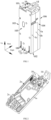
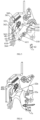
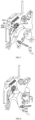
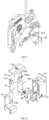
- FIGs.1-4 there is an embodiment of the plug-in circuit breaker of the present invention.
- the plug-in circuit breaker of the present invention includes a circuit breaker housing and at least one protective pole, wherein the circuit breaker housing includes at least one protective pole-mounting cavity fitting with the protective pole by one-to-one, each protective pole includes the operating button 1d, the operating mechanism 3 arranged inside the protective pole-mounting cavity and drivingly connected with the operating button 1d, the protecting mechanism 4 drivingly cooperated with the operating mechanism 3, the arc extinguishing system 5, the first wire-inlet terminal 110, the first wire-outlet terminal 11, the movable contact 61 connected with the operating mechanism 3, and the stationary contact 62 fitting with the movable contact 61.
- One end of the operating button 1d is inserted into the circuit breaker housing, at one end of which the operating button 1d and the first wire-outlet terminal 11 are both arranged, and at the other end of which the first wire-inlet terminal 110 is arranged.
- the arc extinguishing system 5 is arranged in the middle of the protective pole-mounting cavity and positioned on one side of the first wire-inlet terminal 110, the operating mechanism 3 is arranged between the operating button 1d and the arc extinguishing system 5, and the protecting mechanism 4 is arranged between the first wire-outlet terminal 11 and the arc extinguishing system 5 and positioned on one side of the operating mechanism 3.
- the plug-in circuit breaker of the present invention is a two-pole circuit breaker, including a protective pole and a neutral pole, wherein the protective pole is a L pole, and the neutral pole is a N pole.
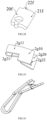
- the plug-in circuit breaker also includes a circuit breaker housing composed of the front cover 1c, the base 1b and the rear cover 1a, wherein the front cover 1c and the base 1b define the protective pole mounting cavity fitting with the protective pole by one-to-one, and the base 1b and the rear cover 1a define the neutral pole mounting cavity fitting with the neutral pole.
- the circuit breaker housing includes the upper side 101, the lower side 102, the front side 105, the rear side 106, the left side 103 and the right side 104.
- the lower end of the operating button 1d is inserted in the circuit breaker housing, the operating button 1d and the first wire-outlet terminal 11 are arranged on the upper end of the circuit breaker housing, the first wire-inlet terminal 110 is arranged on the lower end of the circuit breaker housing, the arc extinguishing system 5 is arranged in the middle of the protective pole mounting cavity and positioned on the upper side of the first wire-inlet terminal 110, the operating mechanism 3 is arranged between the operating button 1d and the arc extinguishing system 5, the protecting mechanism 4 is arranged between the first wire-outlet terminal 11 and the arc extinguishing system 5 and positioned on the left side of the operating mechanism 3.
- the neutral pole further includes the second wire-inlet terminal 100 arranged with the first wire-inlet terminal 110 side by side on lower end of the circuit breaker housing, and the second wire-outlet terminal 10 arranged with the first wire-outlet terminal 11 side by side on the upper end of the circuit breaker housing, and the second wire-inlet terminal 100 is electrically connected with the second wire-outlet terminal 10 through the second electroconductive plate 2a.
- the first wire-inlet terminal 110 and the second wire-inlet terminal 100 are arranged on the right and left parts of the lower end of the circuit breaker housing, respectively; the first wire-outlet terminal 11 and the second wire-outlet terminal 10 are both arranged on the left side of the operating button 1d.
- the first wire-inlet terminal 110 and the second wire-inlet terminal 100 both include the first elastic elements 2c, each of which includes a first reed connecting plate and two first reed clamping plates arranged opposite to each other, which are crookedly connected with the two ends of the first reed connecting plate respectively, and each first reed clamping plate has a " ⁇ " structure, thus the two first reed clamping plates are integrally formed into an X-shaped structure.
- FIGs 3-7 there is the first embodiment of the operating mechanism 3 in the plug-in circuit breaker of the present invention.
- the operating mechanism 3 of the first embodiment includes the U-shaped connecting rod 35,the operating handle 30, the contact supporting rod 31, the jump buckle 32, the lock catch 36, the lock catch-resetting spring 37 and the main tension spring 33.
- the operating handle 30 is pivotally arranged on the circuit breaker housing. One end of the operating handle 30 is drivingly connected with the operating button 1d by the U-shaped connecting rod 35, and the other end of the operating handle 30 is rotatably connected with one end of the contact supporting rod 31, the other end of which is provided with the movable contact 61.
- the jump buckle 32 has one end pivotally arranged on the circuit breaker housing, and the middle part connected with the end of the contact supporting rod 31 provided with the movable contact 61 by the main tension spring 33.
- the arc isolating plate 34 When the plug-in circuit breaker is in the break-contact state, the arc isolating plate 34 enters between the movable contact 61 and the stationary contact 62, in the make-contact state, the arc isolating plate 34 moves out between the movable contact 61 and the stationary contact 62.
- the contact supporting rod 31 further includes the linkage member 44 having the linkage rod 440 and the linkage shaft 441 arranged at one end of the linkage rod 440.
- the linkage shaft 440 has two ends respectively pivoted on the circuit breaker housing and the middle provided with the polygonal hole 4410 in its axial direction, and the side of the linkage rod 440 opposite to the jump buckle 32 is provided with the linkage member activated stand 442.
- the second jump buckle arm 32b is provided with the linkage member activating stand 322 that is drivingly cooperated with the linkage member activated stand 442.
- the plug-in circuit breaker includes a plurality of protective poles, the linkage shafts 441 of which are connected with each other by linkage member connecting shafts, and the linkage member connecting shafts fit with the polygonal hole 4410 of each linkage member 44, respectively.
- the linkage member activating stand 322 of the jump buckle 32 of the protective pole drives the linkage rod 440 to swing by the linkage member activated stand 442, thus the linkage rod 440 drives the linkage shaft 441 to rotate, and the linkage shaft 441 drives the linkage rods 440 of other protective poles to swing by the linkage member connecting shaft, knocking the lock catch 36 of each protective pole, respectively, so as to make each protective pole trip synchronously.
- the linkage members 44 of each protective pole can be connected with each other by one linkage member connecting shaft, or two adjacent protective poles are connected with each other by one linkage member connecting shaft.
- the jump buckle 32 and the contact supporting rod 31 are both arranged below the operating handle 30, and the operating handle 30 has the upper end connected to the operating button 1d by the U-shaped connecting rod 35, the middle pivotally arranged on the circuit breaker housing, and the lower end rotatably connected with the supporting rod rotation shaft 311 on the upper end of the contact supporting rod 31.
- the jump buckle 32 has an U-shaped structure with its opening facing downward, and includes the second jump buckle arm 32b and the first jump buckle arm 32a respectively arranged on the left and right sides of the jump buckle 32.
- the first jump buckle arm 32a has the upper end pivotally arranged on the circuit breaker housing, and the upper end connected to the upper end of the second jump buckle arm 32b, and the lower end of the second jump buckle arm 32b is locked with with the lock catch 36.
- the middle of the jump buckle 32 is connected with the upper end of the movable contact plate 610 of the contact supporting rod 31 by the main tension spring 33.
- the contact supporting rod 31 has the upper end stacked on the front side of the middle of the jump buckle 32, and the lower end provided with the movable contact 61 including the movable contact plate 610, and the movable contact plate 610 has the right side of the lower end provided with the movable contact point 611, and the upper end connected to the lower end of the main tension spring 33.
- the arc isolating plate 34 has the left end rotatably connected with the lower end of the contact supporting rod 3, and the right end fitting with the movable contact 61 and the stationary contact 62, extends between the movable contact 61 and the stationary contact 62 in the break-contact state, and moves out between the movable contact 61 and the stationary contact 62 in the make-contact state.
- the contact supporting rod 31 is provided with the rod-barrier limit groove, when the contact supporting rod 31 drives the movable contact 61 and the stationary contact 62 to be in the break/make-contact state, the rod-barrier limit groove drives the arc isolating plate 34 to extend into and out of the space between the movable contact and the stationary contact and limits the swing scope of the right end of the arc isolating plate 34.
- the lock catch 36 is arranged on the left side of the jump buckle 32, and has the middle part pivotally arranged, the upper end connected to the circuit breaker housing by the lock catch-resetting spring 37, and the lower end interlocked with the lower end of the second jump buckle arm 32b of the jump buckle 32.
- the linkage member 44 is arranged between the lock catch 36 and the jump buckle 32, and the linkage rod 440 has the upper end pivoted by the linkage shaft 441, and the middle part positioned on the right side below the linkage shaft 441 and provided with the linkage member activated stand 442.
- the left side of the upper end of the second jump buckle arm 32b is provided with the linkage member activating stand 322 drivingly cooperated with the linkage member activated stand 442.
- the operating handle 30 is pivotally arranged on the circuit breaker housing by the operating handle mounting shaft 14. Further, both ends of the operating handle mounting shaft 14 are pivotally connected to the front cover 1c and the base 1b, respectively.
- the operating handle 30 further includes a handle-connection hole fitting with the U-shaped connecting rod 35, a handle-support hole fitting with the supporting rod rotation shaft 311 of the contact supporting rod 31, and a handle shaft hole fitting with the operating handle mounting shaft 14.
- the shape of the operating handle 30 is approximately a triangle, at three vertices of which there are the handle-connection hole, the handle shaft hole and the handle-support hole respectively arranged.
- the lower end of the first jump buckle arm 32a of the jump buckle 32 is pivotally arranged on the circuit breaker housing by the jump buckle mounting shaft 15. Further, the two ends of the jump buckle mounting shaft 15 are pivotally connected to the front cover 1c and the base 1b, respectively.
- the middle of the jump buckle 32 is provided with the jump buckle-spring connection hole 320 connected with one end of the main tension spring 33, and the upper end of the movable contact plate 610 is provided with the movable contact plate-spring connection hole 310.
- the lower end of the second jump buckle arm 32b has a wedge-shaped structure, and the lower end of the jump buckle 36 is provided with the lock catch hole 363 interlocked with the lower end of the second jump buckle arm 32b.
- FIGs.8-9 there is the second embodiment of the operating mechanism 3 in the plug-in circuit breaker of the present invention.
- the operating mechanism 3 of the second embodiment is different from that of the first embodiment in that it further includes the jump buckle-resetting spring 38, one end of which is connected with the circuit breaker housing, and the other end of which is connected with the jump buckle 32.
- the protecting mechanism 4 actuates the lock catch 36 to release the coupling with the jump buckle 32, then the plug-in circuit breaker trips, and the jump buckle-resetting spring 38 actuates the jump buckle 32 to rotate, so that the jump buckle 32 is recoupled with the lock catch 36, meanwhile the plug-in circuit breaker enters the break-contact state.
- the jump buckle-resetting spring 38 is a torsion spring encircling the jump buckle-resetting spring shaft 380 positioned on one side of the first jump buckle arm 32a, and the two ends of the jump buckle-resetting spring shaft 380 are fixed on the circuit breaker housing, respectively.
- the middle of the first jump buckle arm 32a is provided with the jump buckle-resetting protrusion 323, and the jump buckle-resetting spring 38 has one end connected with the circuit breaker housing, and the other end connected with the jump buckle 32.
- the jump buckle-resetting spring 38 enables the jump buckle 32 to rotate clockwise by the jump buckle-resetting protrusion 323 until the lower end of the second jump buckle arm 32b is relocked with the lock catch 36 again.
- FIGs.3-9 there is an embodiment of the protecting mechanism 4 in the plug-in circuit breaker of the present invention.
- the protecting mechanism 4 includes the magnetic yoke 40 and the dual metal piece 42.
- the magnetic yoke 40 is arranged on one side of the lock catch 36
- the dual metal piece 42 is arranged at the middle of the magnetic yoke 40 and positioned between the magnetic yoke 40 and the lock catch 3, having one end fixedly arranged and electrically connected with the first wire-outlet terminal 11, and the other end drivingly cooperated with the lock catch 36 and electrically connected with the movable contact 61.
- the dual metal piece 42 is arranged at the middle of the magnetic yoke 40 and positioned between the magnetic yoke 40 and the lock catch 36, and the lock catch 36 has the upper end fixedly arranged, the middle part rotatably arranged, and the lower end arranged opposite to the magnetic yoke 40, drivingly cooperated with the dual metal piece 42 and interlocked with the jump buckle 32.
- the lock catch 36 has the middle rotatably arranged on one end of the magnetic yoke 40, one end connected with the circuit breaker housing by the lock catch-resetting spring 37, and the other end arranged opposite to the magnetic yoke 40.
- the dual metal piece 42 has the fixed end electrically connected with the first wire-outlet terminal 11 by the first electroconductive plate 2b (see FIG.3 ), the other end electrically connected with the contact supporting rod 31 through the soft connection 63, and the stationary contact 62 is electrically connected with the first wire-inlet terminal 110.
- the protection mechanism 4 also includes an adjustment screw which is in limit fit with the circuit breaker housing, and which has one end threadedly engaged with the end of the first electroconductive plate 2b connected with the dual metal piece 42, so as to adjust the position of the dual metal piece 42, and furthermore the tripping threshold or parameter of the dual metal piece 42.
- the lock catch 36 has the middle rotatably arranged on the upper end of the magnetic yoke 40, the upper end connected with the circuit breaker housing by the lock catch-resetting spring 37, and the lower end arranged opposite to the magnetic yoke 40.
- the dual metal piece 42 has the upper end electrically connected with the first wire-outlet terminal 11 by the first electroconductive plate 2b, and the lower end electrically connected with the contact supporting rod 31 through the soft connection 63, and the stationary contact 62 is electrically connected with the first wire-inlet terminal 110.
- the first electroconductive plate 2b is electrically connected with the contact supporting rod 31 through a second soft connection, adding a circuit extending from the second electroconductive plate 2b to the contact supporting rod. Therefore, when a short-circuit fault occurs in a plug-in circuit breaker specified with a large ampere rated current, the current flowing in the dual metal piece is reduced, avoiding the occurrence of the failure of the dual metal piece from being overheated due to an excessive current.
- the cross section of the magnetic yoke 40 has a shaped structure, and one end of the magnetic yoke 40 is provided with two yoke supporting arms 400 arranged opposite to each other (see FIG.6 ), on which there is the yoke limiting groove 401 arranged.
- the lock catch 36 includes the lock catch-resetting end 360, the lock catch supporting arm 361, the lock catch body 362, the lock catch hole 363 and the lock catch activated end 364 (see FIG. 5 ), and the lock catch-resetting end 360, the lock catch body 362 and the lock catch activated end 364 are connected with each other in sequence.
- the lock catch-supporting arm 361 is arranged on both sides of the connection between the lock catch-resetting end 360 and the lock catch body 362, and the lock catch activated end 364 has a L-shaped structure, one end crookedly connected with the lock catch body 362, and the other end drivingly cooperated with the dual metal piece 42.
- the two lock catch-supporting arms 361 are respectively arranged inside two yoke limiting grooves 401, the lock catch body 362 is arranged opposite to the magnetic yoke 400, and the lock catch hole 363 is arranged on the lock catch body 362 and interlocked with the jump buckle 32.
- the lock catch body 362 has the upper end crookedly connected with the lock catch-resetting end 360, and the lower end crookedly connected with the lock catch activated end 364. While the lock catch-resetting end 360 bends to the right, the lock catch activated end 364 bends to the left, and the lock catch hole 363 is arranged in the middle of the lock catch body 362 to fit with the magnetic yoke 40.
- FIGs.3-4 there is an embodiment of the arc extinguishing system 5 in the plug-in circuit breaker of the present invention.
- the arc extinguishing system 5 includes the arc extinguishing chamber 50, and the movable contact arcing plate 51 and the stationary contact arcing plate 52 respectively arranged on both sides of the arc extinguishing chamber 50.
- the movable contact arcing plate 51 fits with the movable contact 61 and is electrically connected with the first wire-outlet terminal 11, and the stationary contact arcing plate 52 has one end provided with the stationary contact 62, and the other end electrically connected with the first wire-inlet terminal 110.
- the movable contact arcing plate 51 and the stationary contact arcing plate 52 are respectively arranged on the left and right sides of the arc extinguishing chamber 50, and the movable contact arcing plate 51 is electrically connected with the first wire-outlet terminal 11 and has the upper end fitting with the movable contact 61.
- the stationary contact arcing plate 52 has the upper end provided with the stationary contact 62, and the lower end electrically connected with the first wire-inlet terminal 110, and the upper end of the movable contact arcing plate 51 and the upper end of the stationary contact arcing plate 52 bend to each other.
- the plug-in circuit breaker of the present invention further includes at least two auxiliary signal terminals that are connected to external circuits in a plug-in and plug-out mode.
- Each auxiliary signal terminal is electrically connected to the first wire-outlet terminal 11, and a signal processing element is connected in series between at least one auxiliary signal terminal and the first wire-outlet terminal 11.
- the signal processing element includes at least one diode.
- a signal processing element is connected in series between each auxiliary signal terminal and the first wire-outlet terminal 11, or a signal processing element is connected in series between one auxiliary signal terminal and the first wire-outlet terminal 11, and a signal processing element is not connected in series between another auxiliary signal terminal and the first wire-outlet terminal 11.
- the plug-in circuit breaker of the present invention preferably adopts the latter method, so that the plug-in circuit breaker can output a DC signal through one auxiliary signal terminal and output an AC signal through another auxiliary signal terminal, so as to strengthen the adaptability of the plug-in circuit breaker and ensure to meet the requirements of different application environments.
- the signal processing element is not limited to diodes, may be other elements capable of converting an AC signal into a DC signal.
- the signal processing element can also be simply added with functions according to user needs.
- the plug-in circuit breaker of the present invention includes two auxiliary signal terminals that are connected to the external circuit in a plug-in and plug-out mode, which are the first auxiliary signal terminal 12 and the second auxiliary signal terminal 13 respectively, and each auxiliary signal terminal is electrically connected with the first wire-outlet terminal 11 by the movable contact arcing plate 51, and one diode is connected in series between the second auxiliary signal terminal 13 and the movable contact arcing plate 51. Further, as shown in FIGs.
- the first wire-inlet terminal 110, the second wire-inlet terminal 100, the first auxiliary signal terminal 12 and the second auxiliary signal terminal 13 are all arranged on the lower end of the plug-in circuit breaker, the first auxiliary signal terminal 12 and the second auxiliary signal terminal 13 are arranged side by side between the first wire-inlet terminal 110 and the second wire-inlet terminal 100.
- the auxiliary signal terminal can be connected to a circuit structure such as an external control circuit board, so as to realize for example remote monitoring.
- each auxiliary signal terminal includes the second elastic elements 2d, each of which includes a second reed connecting plate and two second reed clamping plates arranged opposite to each other, which are crookedly connected with the two ends of the second reed connecting plate respectively, and each second reed clamping plate has a " ⁇ " structure, thus the two second reed clamping plates are integrally formed into an X-shaped structure.
- the plug-in circuit breaker of the present invention further includes the air exhaust opening 16, and a first exhaust passage is also provided in the protective pole mounting cavity.
- the first exhaust passage has one end communicating with the air vent of the arc extinguishing chamber 50 of the arc extinguishing system 5, and the other end communicating with the external environment through the air exhaust opening 16.
- the air exhaust opening 16 is arranged on the lower end surface of the circuit breaker housing and positioned between the second auxiliary signal terminal 13 and the first wire-inlet terminal 110 .
- one end of the operating button 1d inserted inside the circuit breaker housing is a button inner end, and the other end of the operating button 1d protruding outside the circuit breaker housing is a button outer end.
- An indicator slot is arranged inside the operating button 1d, the indicating hole 12d is arranged on the button outer end, and the indicating hole 12d communicates with one end of the indicator slot.
- the plug-in circuit breaker further includes the indicating member 7 slidably inserted into the indicator slot, one end of the indicating member 7 is provided with the make-contact indicating surface 70 and the break-contact indicating surface 71 both respectively fitting with the indicating hole 12d.
- the break-contact indicating surface 71 When the plug-in circuit breaker is in the break-contact state, the break-contact indicating surface 71 is arranged opposite to the indicating hole 12d, thus during pressing the operating button 1d to move it toward the make-contact position, the indicating member 7 moves in its entirety inside the indicator slot. After the plug-in circuit breaker enters the make-contact state, the make-contact indicating surface 70 is arranged opposite to the indicating hole 12d, thus during pulling the operating button 1d to move it toward the break-contact position, the indicating member 7 moves in its entirety inside the indicator slot. After the plug-in circuit breaker enters the break-contact state, the break-contact indicating surface 71 is arranged opposite to the indicating hole 12d.
- the movement direction of the operating button 1d is perpendicular to the movement direction of the indicating member 7 within the indicator slot.
- the operating button 1d further includes the indicator sliding groove 100d respectively arranged on a pair of side walls of the indicator slot, and the extension direction of the indicator sliding groove 100d is perpendicular to the movement direction of the operating button 1d.
- the indicating member 7 further includes two indicator sliding stands 72 respectively arranged on a pair of side surfaces thereof, and the indicator sliding stand 72 is slidably arranged in the indicator sliding groove100d to restrict the movement path of the indicating member 7 inside the indicator sliding groove 100d.
- the indicating member 7 further includes the indicator tracking shaft 75 arranged at the other end of the indicating member 7.
- an indicator tracking groove is arranged on the circuit breaker housing, and the indicator tracking shaft 75 is slidably arranged in the indicator tracking groove.
- the indicator tracking groove drives the indicating member 7 to move in its entirety in the indicator slot by the indicator tracking shaft 75, so that the make-contact indicating surface 70/break-contact indicating surface 71 is arranged opposite to the indicating hole 12d.
- the indicator tracking groove is an inclined tracking groove, which may be slantingly arranged in a straight line or in an arc.
- a actuating protrusion can be provided on the circuit breaker housing, so that the indicating member moves horizontally with respect to the operating button 1d by means of the fit between the inclined actuating surface and the actuating protrusion, when the operating button 1d is pressed/pulled.
- the indicator tracking groove is an inclined tracking groove, which is formed by means of the fit between two inclined half-grooves arranged opposite to each other on the circuit breaker housing.
- the indicator tracking shaft 75 When the plug-in circuit breaker is in the break-contact state, the indicator tracking shaft 75 is positioned at one end of the indicator tracking groove, which is the first tracking groove end; when the plug-in circuit breaker is in the make-contact state, the indicator tracking shaft 75 is positioned at the other end of the indicator tracking groove, which is the second tracking groove end.
- the first tracking groove end is closer to the button outer end of the operating button 1d than the second tracking groove end.
- make-contact indicating surface 70 and the break-contact indicating surface 71 may be different from each other in color, for example, the make-contact indicating surface is green, but the break-contact indicating surface is red; or the make-contact indicating surface 70 and the break-contact indicating surface 71 may be different from each other in characters or symbol identification, for example, the make-contact indicating surface 70 has the word " make-contact " or the symbol "
- the operating button 1d has the upper end as the button outer end, and the lower end as the button inner end, and the end face of the button outer end is provided with the indicating hole 12d, which is connected with the upper end of the indicator slot.
- the make-contact indicating surface 70 and the break-contact indicating surface 71 are arranged side by side at the upper end of the indicating member 7, the two indicator sliding stands 72 are arranged on both sides of the middle of the indicating member 7, and the indicator tracking shaft 75 is arranged at the lower end of the indicating member 7.
- the indicator tracking groove is formed by means of the fit between two inclined half grooves, one inclined half groove is arranged on the rear cover 1a, being the first half groove 10a, and the other inclined half groove is arranged on the base 1b, being the second half groove 10b.
- the upper right end of the indicator tracking groove is the first tracking groove end, and the lower left end is the second tracking groove end.
- the operating button 1d when the plug-in circuit breaker is in the break-contact state, thus the operating button 1d is pressed down (the operating button 1d moves toward the make-contact position), as the operating button 1d moves linearly, and the indicator tracking groove is inclined from the upper right to the lower left, therefore the indicator tracking groove actuates the indicating member 7 to move laterally by the indicator tracking shaft 75 (the indicating member 7 moves in its entirety in the indicator slot), so as to switch from the configuration of the break-contact indicating surface 71 opposite to the indicating hole 12d to the configuration of the make-contact indicating surface 70 opposite to the indicating hole 12d.
- the operating button 1d When the plug-in circuit breaker is in the make-contact state, the operating button 1d is pulled upward, thus the indicating member 7 goes through the process opposite to above-mentioned process.
- the plug-in circuit breaker of the present invention further includes a locking mechanism, wherein the locking mechanism includes the second locking member 8 pivotally arranged in the middle, the second locking member 8 includes the locking member upper end and the locking member lower end respectively arranged at both ends thereof, and the locking member lower end is provided with the second protrusion 82.
- the locking mechanism includes the second locking member 8 pivotally arranged in the middle, the second locking member 8 includes the locking member upper end and the locking member lower end respectively arranged at both ends thereof, and the locking member lower end is provided with the second protrusion 82.
- the operating button 1d When the plug-in circuit breaker is in the make-contact state, the operating button 1d actuates the second locking member 8 to rotate by the locking member lower end, so that the second protrusion 82 protrudes outside the circuit breaker housing; when the plug-in circuit breaker is in the break-contact state, the operating button 1d actuates the second locking member 8 to rotate by the locking member upper end, so that the second protrusion 82 moves into the circuit breaker housing.
- the indicating member 7 further includes the indicator horizontal arm 74 arranged at one end thereof.
- the second locking member 8 further includes the second locking member activated portion 81 arranged at the locking member upper end, and the operating button 1d are drivingly cooperated with the second locking member activated portion 81 by the indicator horizontal arm 74 to drive the second locking member 8 to rotate, so that the second protrusion 82 moves into the circuit breaker housing. Further, as shown in FIGs.11, 12 and 17 , the second locking member 8 further includes the second locking member activated protrusion 83 arranged at the locking member lower end, and the second locking member activated protrusion 83 protrudes in the reverse direction of the second protrusion 82.
- the indicator horizontal arm 74 is positioned on one side of the second locking member activated protrusion 83 and in limit fit with it, so as to keep the second protrusion 82 protruding outside the circuit breaker housing.
- the indicator horizontal arm 74 is arranged on the lower end of the indicating member 7 and connected with the right angle thereof, and protrudes to the left
- the second locking member activated portion 81 is arranged on the upper end of the second locking member 8 and connected with the right angle thereof, and protrudes to the right.
- the second protrusion 82 (In FIG.18 , the second protrusion 82 is screened by the first locking member 9) and the second locking member activated protrusion 83 are both arranged on the lower end of the second locking member 8 and protrude to the left and right sides of the second locking member 8 respectively, and the indicator horizontal arm 74 is positioned on the lower side of the second locking member activated portion 81 and drivingly cooperated with it.
- the operating button 1d actuates the second locking member 8 to rotate counterclockwise by means of the fit between the indicator horizontal arm 74 and the second locking member activated portion 81, so that the second protrusion 82 moves into the circuit breaker housing.
- the operating button 1d moves down, and the indicator horizontal arm 74 abuts against the second locking member activated protrusion 83, so that the second locking member 8 rotates counterclockwise, thus the second protrusion 82 protrudes outside the circuit breaker housing.
- the indicator horizontal arm 74 is positioned on the left side of the second locking member activated protrusion 83 and in limit fit with it, the second protrusion 82 keeps protruding outside the circuit breaker housing.
- the indicator horizontal arm 74 of the indicating member 7 keeps the second protrusion 82 of the second locking member 8 protruding outside the circuit breaker housing, preventing the circuit breaker from being installed under the make-contact state and occurrence of electric shock, and facilitating improving the user's electricity safety.
- the actuation of the second locking member 8 is not only limited to the actuation under the indicator horizontal arm 74, a structure similar to the indicator horizontal arm 74 is but also arranged on the lower end of operating button 1d to actuate the second locking member 8.
- the locking mechanism further includes the first locking member 9, which has one end slidably arranged inside the circuit breaker housing, and the other end being the first protrusion 90 protruding outside the circuit breaker housing.
- the housing of the circuit breaker assembling position presses the first protrusion 90, so that the first locking member 9 moves in its entirety to the inside of the circuit breaker housing.
- the first protrusion 90 protrudes outside the circuit breaker housing and is in limit fit with the housing of the circuit breaker assembling position.
- the first locking member 9 is in limit fit with the housing of the circuit breaker assembling position, ensuring the assembly reliability of the plug-in circuit breaker, preventing the plug-in circuit breaker from being pulled out by mistake under the make-contact state, and improving the user's electricity safety.
- the locking member lower end of the second locking member 8 is drivingly cooperated with the first locking member 9.
- pulling the operating button actuates the first locking member 9 to move in its entirety toward the inside of the circuit breaker housing by the second locking member 8, so as to release the limit fit between the first protrusion 90 and the housing of the circuit breaker assembling position.
- the first sliding end 90 a further includes the first activated protrusion 91 and the second activated protrusion 94.
- the second locking member 8 further includes the second locking member body 84 pivotally arranged in the middle, the second locking member activated portion 81 of the second locking member 8 is crookedly connected with one end of the second locking member body 84, and the other end of the second locking member body 84 is provided with the second protrusion 82 and drivingly cooperated with the second activated protrusion 94.
- the second locking member activated portion 81 and the second protrusion 82 protrude toward the both sides of the second locking member body 84, respectively, and the second protrusion 82 is drivingly cooperated with the first activated protrusion 91.
- first locking member 9 can exclude the first activated protrusion 91 or the second activated protrusion 94, thus retain either of the two to fit with the second locking member 8. Of course, such improvement will abate the stability and reliability of the action of the first locking member 9.
- the first locking member 9 further includes the first sliding end 90a slidably arranged inside the circuit breaker housing, wherein the first sliding end 90a has one side connected with the first protrusion 90, and the other side connected with the circuit breaker housing by the first locking member resetting spring 9a applying a force to the first locking member 9 to keep the first protrusion 90 protruding outside the circuit breaker housing.
- the upper end of the second locking member activating portion 84 is crookedly connected with the second locking member activated portion 81 (connected at a right angle or approximately at a right angle), the second protrusion 82 is arranged on the edge of one side edge of the lower end of the second locking member body 84, and the lower end of the second locking member activating portion 84 and the second protrusion 82 are arranged on the right sides of the second activated protrusion 94 and the first activated protrusion 91, respectively.
- the circuit breaker housing is provided with the first opening 11 a fitting with the first protrusion 90 and the second protrusion 82.
- the first opening 11a is arranged on the right side of the circuit breaker housing, and the first protrusion 90 and the second protrusion 82 protrude outside the circuit breaker housing through the first opening 11a, respectively.
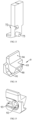
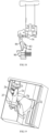
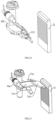
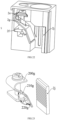
- FIGs.11-18 there is an embodiment of the locking mechanism in the plug-in circuit breaker of the present invention.
- the locking mechanism includes the first locking member 9, the second locking member 8 and the indicating member 7.
- the indicating member 7 has one end inserted into the operating button 1d, and the other end drivingly cooperated with the second locking member 8, and the second locking member 8 has the middle pivotally arranged, and one end drivingly cooperated with the first locking member 9.
- the first locking member 9 further includes the first sliding end 90a and the first protrusion 90 respectively arranged both end thereof, wherein the first sliding end 90a has one side connected with the first protrusion 90, and the other side connected with the circuit breaker housing by the first locking member resetting spring 9a.
- the first sliding end 90a includes the spring-limiting groove 92 arranged on one side thereof, and a spring-limiting protrusion is also arranged in the middle of the spring-limiting groove 92.
- One end of the first locking member resetting spring 9a is inserted into the spring-limiting groove 92, and encircles the spring-limiting protrusion.
- the first sliding end 90a is provided with the first tracking groove 93 fitting with the first sliding track on the circuit breaker housing to define a sliding path of the first sliding end 90a.
- the first sliding end 90a further includes the first activated protrusion 91 and the second activated protrusion 94, wherein the first activated protrusion 91 and the first tracking groove 93 are respectively arranged at both ends of the first sliding end 90a, and the second activated protrusion 94 are arranged on the upper side of the first sliding end 90a and positioned between the first activated protrusion 91 and the first tracking groove 93.
- the second locking member 8 includes the second locking member activated portion 81, the second locking member body 84, the second locking member activated protrusion 83, the second locking member activated protrusion 83 and the second protrusions 82.
- the second locking member body 84 has the middle part pivotally arranged on the circuit breaker housing by the second locking member mounting shaft 80, one end crookedly connected with the second locking member activated portion 81, and the other end provided with the second locking member activated protrusion 83 and the second protrusions 82.
- the second locking member activated portion 81 and the second protrusion 82 protrude toward both sides of the second locking member body 84, respectively, and the second locking member activated portion 81 and the second locking member activated protrusion 83 both protrude on the identical side of the second locking member body 84.
- the second locking member 8 includes a locking member upper end and a locking member lower end respectively arranged on the upper and lower ends thereof, and the second locking member activated portion 81 is crookedly connected with the second locking member body 84 (connected at a right angle or approximately at a right angle) to form the locking member upper end; the second locking member activated protrusion 83 and the second protrusions 82 are both arranged on the lower end of the second locking member body 84, thus the second protrusion 82 and the lower end of the second locking member body 84 form the locking member lower end.
- the middle of the second locking member body 84 is provided with the second locking member mounting shaft 80, both ends of which are pivotally connected to the circuit breaker housing, respectively.
- the lower end of the second locking member body 84 is drivingly cooperated with the second activated protrusion 94, and the second locking member activated protrusion 83 is arranged at the edge of one side of the lower end of the second locking member body 84(as shown in FIG. 10 , the second locking member activated protrusion 83 is arranged at the edge of the left side of the lower end of the second locking member body 84).
- the second protrusion 82 protrudes below the lower end of the second locking member body 84 and is connected with the second locking member activated protrusion 83 (As shown in FIG.
- the second locking member activated portion 81 and the second locking member body 84 integrally form a L-shaped structure
- the second locking member activated protrusion 83 and the second protrusion 82 are an integral plate structure, and positioned in their entirety on the left side of the above-mentioned L-shaped structure, and the upper end is the second locking member activated protrusion 83 connected with the lower end of the second locking member body 84, and the lower end is the second protrusion 82 protruding below the lower end of the second locking member body 84.
- the second locking member activated portion 81 and the second protrusion 82 protrude toward both sides of the second locking member body 84, respectively, the second locking member activated portion 81 and the second locking member activated protrusion 83 protrude toward the identical side of the second locking member body 84, and the second protrusion 82 is drivingly cooperated with the first activated protrusion 91.
- the indicating member 7 includes the indicator body 7-0, the indicator horizontal arm 74, the indicator tracking shaft 75, the indicator sliding stand 72, the make-contact indicating surface 70 and the break-contact indicating surface 71.
- the indicator horizontal arm 74 is arranged on one end of the indicator body 7-0 and crookedly connected with the indicator body 7-0, the make-contact indicating surface 70 and the break-contact indicating surface 71 are arranged side by side on the other end of the indicator body 7-0, two indicator sliding stands 72 are respectively arranged on both sides of the middle part of the indicator body 7-0.
- the indicating member 7 further includes the indicator vertical arm 73, wherein the indicator vertical arm 73 and the indicator horizontal arm 74 are arranged on the identical end of the indicator body 70, both have a L-shaped structure in their entirety, thus the indicator vertical arm 73 helps to improve the structural strength of the indicator horizontal arm 74.
- the make-contact indicating surface 70 and the break-contact indicating surface 71 are arranged side by side on the upper end surface of the indicator body 7-0.
- the indicator horizontal arm 74, the indicator tracking shaft 75 and the indicator vertical arm 73 are all arranged on the lower end surface of the indicator body 7-0.
- the indicator horizontal arm 74 and the indicator vertical arm 73 are arranged on the identical side of the indicator body 7-0 in a L-shaped structure as a whole, and the indicator tracking shaft 75 is arranged on the other side of the indicator body 7-0.
- Two indicator sliding stands 72 are respectively arranged on the middle parts of both sides of the indicator body 7-0, and both positioned between the break-contact indicating surface 71 and the indicator horizontal arm 74.
- the circuit breaker housing is provided with an indicator tracking groove fitting with the indicator tracking shaft 75.
- the indicator tracking groove is obliquely arranged as an tracking groove inclined from the upper right end to the lower left end.
- the indicator tracking groove includes a first vertical groove, an inclined groove and a second vertical groove, wherein the lower end of the first vertical groove is connected with the upper right end of the inclined groove, the upper end of the second vertical groove is connected with the lower left end of the inclined groove, and the lower end of the first vertical groove is higher than the upper end of the second vertical groove.
- the indicator tracking groove is composed of two inclined half-grooves fitting with each other, in particular, one inclined half-groove is arranged on the rear cover 1a, and the other inclined half-groove is arranged on the base 1b.
- the operating button 1d includes the button body 10d and the button cap arranged at one end of the button body 10d, wherein the middle of the button cap is provided with the indicating hole 12d, the middle of the other end of the button body 10d is provided with the indicator slot, two side walls of the indicator slot are respectively provided with one indicator groove 100d.
- the operating button 1d further includes the button connecting stand 11d rotatably connected to one end of the U-shaped connecting rod 35.
- the operating button 1d actuates the second locking member 8 to rotate clockwise through the fit between the indicator horizontal arm 74 of the indicating member 7 and the second locking member activated portion 81 of the second locking member 8, thus the second protrusion 82 of the second locking member 8 is moved inside the circuit breaker housing, in this state (break-contact), the plug-in circuit breaker can be installed into the circuit breaker assembling position (eg, a cabinet).
- the operating button 1d drives the indicator horizontal arm 74 to move down, thus the indicator horizontal arm 74 drives the second locking member 8 to rotate counterclockwise by the second locking member activated protrusion 83, so that the second protrusion 82 protrudes outside the circuit breaker housing, in this state (make-contact), the second protrusion 82 protrudes outside the circuit breaker housing.
- the second locking member activated protrusion 83 is confined by the indicator horizontal arm 74, the second protrusion 82 cannot be pressed into the circuit breaker housing, so when the plug-in circuit breaker is in the make-contact state, it cannot be assembled to the circuit breaker assembling position.
- the indicating member 7 When the plug-in circuit breaker is switched between the break-contact state and the make-contact state, due to the fit between the indicator tracking shaft 75 and the indicator tracking groove, the indicating member 7 will also move back and forth in the indicator slot of the operating button 1d.
- the make-contact indicating surface 70 when the plug-in circuit breaker is in the make-contact state, the make-contact indicating surface 70 is opposite to the indicating hole 12d (preferably, the indicator tracking shaft 75 is positioned at the connection between the second vertical groove and the inclined groove); when the plug-in circuit breaker is in the break-contact state, the break-contact indicating surface 70 is opposite to the indicating hole 12d (preferably, at this time, the indicator tracking shaft 75 is positioned at the connection between the first vertical groove and the inclined groove, and if the operating button 1d is continuously pulled, the indicator tracking shaft 75 slides along the first vertical groove to the second locking member 8, so as to actuate the first locking member 9 to release the limit fit with the housing of the circuit breaker assembling position).
- the present invention also relates to a connecting terminal.
- FIGs.19-24 there is an embodiment of the connecting terminal of the present invention.
- the connecting terminal of the present invention includes the connecting screw 2e, the wire-clamping piece 2g, the nut piece 2f and the connecting board 2j; the connecting screw 2e and the nut piece 2f are threadedly connected with each other; the wire-clamping piece 2g is arranged between the nut piece 2f and the nut of the connecting screw, and obliquely arranged with respect to the connecting board 2j, which is fixedly arranged.
- the wire-clamping piece 2g has one end confined, and the other end configured to from a space for connecting wires with respect to the connecting board 2j.
- the nut piece 2f actuates the end of the wire-clamping piece 2g fitting with the connecting board 2j to rise, so as to press the wires between the wire-clamping piece 2g and the connecting board 2j.
- the nut piece 2f is in limit fit with the terminal assembling cavity receiving the connecting terminal, preventing the nut piece 2f from rotating and enabling it to move in axial direction of the connecting screw 2e, thus during screwing the connecting screw 2e, the nut piece 2f reciprocates in the axial direction of the connecting screw 2e.
- the wire-clamping piece 2g has the left end confined, the right end arranged opposite to and fitting with the connecting board 2j, the wire-clamping piece 2g is gradually inclined downward from the left end to the right end with its left end higher than its right end.
- the connecting screw 2e moving up the nut piece 2f in axial direction of the connecting screw 2e, the nut piece 2f actuates the right end of the wire-clamping piece 2g to gradually rise, so as to press wires between the wire-clamping piece 2g and the connecting board 2j.
- the connecting screw 2e when required to remove the wires, the connecting screw 2e needs to be screwed, so that the nut piece 2f moves down in axial direction of the connecting screw 2e, thus reducing the pressure between the wire-clamping piece 2g and the wires helps to better remove the wires.
- one side of the connecting board 2j facing the wire-clamping piece 2g is provided with a plurality of lateral grooves or lateral ribs arranged side by side, and the extension direction of the lateral grooves or lateral ribs is perpendicular to the insertion direction of the wires.
- the pressure applied by the wire-clamping piece 2g on the wires between the wire-clamping piece 2g and the connecting board 2j mainly includes the pressure generated by the deformation of the wire-clamping piece 2g itself and the pressure applied by the nut piece 2f on the wires via the wire-clamping piece 2g.
- the existing connecting terminal that only hinges on the wire-clamping piece 2g to press the wire such connecting wires is more reliable.
- the nut piece 2f may not be in limit fit with the terminal assembling cavity receiving the connecting terminal, only hinging on the friction force generated by the contact between the nut piece 2f and the wire-clamping piece 2g, so as to limit the rotation of the nut piece 2f with the connecting screw 2e.
- the nut piece 2f is a special-shaped part with its gravity center positioned at one end of the nut piece 2f not coinciding with the axis of the connecting screw 2e, an eccentric force is generated to restrict the nut piece 2f from rotating with the connecting screw 2e.
- the nut piece 2f and the connection screw 2e may also be fixedly connected (instead of thread connection) with each other, and the connecting screw 2e is in thread fit with the housing of the terminal assembling cavity.
- the connecting screw 2e is actuated to move, equally actuating the wire-clamping piece 2g.
- FIGs.19-21 there is the first embodiment of the connecting terminal of the present invention.
- the connecting terminal of the present invention includes the connecting screw 2e, the wire-clamping piece 2g, the nut piece 2f, the connecting board 2j, the clamping piece-mounting shaft 2h and the clamping piece-resetting spring 2i; the connecting screw 2e and the nut piece 2f are threadedly connected with each other; the nut piece 2f is in limit fit with the terminal assembling cavity receiving the connecting terminal, preventing the nut piece 2f from rotating, thus during screwing the connecting screw 2e, the nut piece 2f reciprocates in the axial direction of the connecting screw 2e; the wire-clamping piece 2g is arranged between the nut piece 2f and the nut of the connecting screw, and obliquely arranged with respect to the connecting board 2j, which is fixedly arranged.
- the wire-clamping piece 2g has one end provided with the clamping piece shaft sleeve 20g, and the other end arranged opposite to and fitting with the connecting board 2j.
- the clamping piece shaft sleeve 20g encircles the clamping piece-mounting shaft 2h, both ends of which are respectively fixed on the cavity wall of the terminal assembling cavity.
- the clamping piece-resetting spring 2i encircles the clamping piece-mounting shaft 2h, and has one end connected with the cavity wall of the terminal assembling cavity, and other end connected with the wire-clamping piece 2g.
- the clamping piece-resetting spring 2i can actuate the turnup end of the wire-clamping piece 2g to fall while the nut piece 2f moves down, improving the efficiency and convenience of wire removal.
- the wire-clamping piece 2g has the left end provided with the clamping piece shaft sleeve 20g, and the right end arranged opposite to and fitting with the connecting board 2j, the wire-clamping piece 2g is gradually inclined downward from the left end to the right end with its left end higher than its right end.
- the gap between the right end of the wire-clamping piece 2g and the connecting board 2j is the largest, thus wires can be inserted between the wire-clamping piece 2g and the connecting board 2j, then screwing the connecting screw 2e enables the nut piece 2f to moves up in axial direction of the connecting screw 2e.
- the wire-clamping piece 2g includes the wire-clamping piece sleeve 20g, the first connecting portion 21g and the first wire-clamping portion 22g, wherein the first connecting portion 21g has one end connected with the wire-clamping piece sleeve 20g, and the other end crookedly connected with one end of the first wire-clamping portion 22g, and the other end of the first wire-clamping portion 22g fits with the connecting board 2j.
- the first connecting portion 21g has the left end connected with the wire-clamping piece sleeve 20g, and the right end crookedly connected with the left end of the first wire-clamping portion 22g, and the right end of the first wire-clamping portion 22g is arranged opposite to and fits with the connecting board 2j.
- the wire-clamping piece 2g has a L-shaped structure as a whole, the width of the first wire-clamping portion 22g is greater than the width of the first connecting portion 21g, and the length of the wire-clamping piece sleeve 20g is equal to the width of the first connecting portion 21g.
- the connecting screw 2e is arranged at the notch of the L-shaped structure of the wire-clamping piece 2g.
- the nut piece 2f includes the first nut portion 20f threadedly connected with the connecting screw 2e, and the second nut portion 21f crookedly connected with one end of the first nut portion 20f, wherein the first nut portion 20f is arranged opposite to and fits with the first connecting portion 21g, and the second nut portion 21f is arranged opposite to and fits with the first wire-clamping portion 22g.
- the second nut portion 21f is contiguously connected with the first wire-clamping portion 22g (both are substantially parallel to each other), and the right end of the first nut portion 20f is contiguously connected with the right end of the first connecting portion 21g.
- the second nut portion 21f actuates the first wire-clamping portion 22g to gradually rise, meanwhile the second nut portion 21f is gradually separated from the first wire-clamping portion 22g, then coordinating the first nut portion 20f with the first connecting portion 21g actuates the first wire-clamping portion 22g to continue to rise.
- the included angle ⁇ between the first connecting portion 21g and the first wire-clamping portion 22g is greater than the included angle ⁇ between the first nut portion 20f and the second nut portion 21f.
- FIGs.22-24 there is the second embodiment of the connecting terminal of the present invention.
- the connecting terminal of the present invention includes the connecting screw 2e, the wire-clamping piece 2g, the nut piece 2f and the connecting board 2j; the connecting screw 2e and the nut piece 2f are threadedly connected with each other; the nut piece 2f is in limit fit with the terminal assembling cavity receiving the connecting terminal, preventing the nut piece 2f from rotating, thus during screwing the connecting screw 2e, the nut piece 2f reciprocates in the axial direction of the connecting screw 2e; the wire-clamping piece 2g is arranged between the nut piece 2f and the nut of the connecting screw, and obliquely arranged with respect to the connecting board 2j, which is fixedly arranged.
- the wire-clamping piece 2g has one end confined, and the other end arranged opposite to and fitting with the connecting board 2j.
- the nut piece 2f actuates the end of the wire-clamping piece 2g fitting with the connecting board 2j to rise, so as to press the wires between the wire-clamping piece 2g and the connecting board 2j.
- the wire-clamping piece 2g includes the first wire-clamping portion 200g, the second wire-clamping portion 210g and the third wire-clamping portion 220g.
- the first wire-clamping portion 200g encircles the connecting screw 2e through the first opening arranged on it.
- the second wire-clamping portion 210g is provided with the second opening, through which the second wire-clamping portion 210g encircles the connecting screw 2e.
- One end of the first wire-clamping portion 200g is crookedly connected with one end of the second wire-clamping portion 210g; the other end of the second wire-clamping portion 210g is crookedly connected with one end of the third wire-clamping portion 220g; the other end of the third wire-clamping portion 220g fits with the connecting board 2j; the second wire-clamping portion 210g and the third wire-clamping portion 220g are integrally arranged obliquely with respect to the connecting board 2j.
- the nut piece 2f includes the first nut portion 20f threadedly connected with the connecting screw 2e, and the second nut portion 21f crookedly connected with one end of the first nut portion 20f, wherein the first nut portion 20f is arranged opposite to and fits with the second wire-clamping portion 210g, and the second nut portion 21f is arranged opposite to and fits with the third wire-clamping portion 220g.
- connection between the first wire-clamping portion 200g and the second wire-clamping portion 210g is an arc structure, and the included angle ⁇ 1 between the second wire-clamping portion 210g and the third wire-clamping portion 220g is greater than the included angle ⁇ between the first nut portion 20f and the second nut portion 21f.
- the first wire-clamping portion 200g and the second wire-clamping portion 210g are sequentially arranged between the nut of the connecting screw 2e and the nut piece 2f.
- the left end of the third wire-clamping portion 220g is crookedly connected with the right end of the second wire-clamping portion 210g, and the right end of the third wire-clamping portion 220g is arranged opposite to and fits with the connecting board 2j.
- FIGs.25-30 there is another embodiment of the connecting terminal of the present invention.
- the connecting terminal of the present invention includes the connecting screw 2e, the wire-clamping piece 2g, the clamping piece-mounting shaft 2h, the nut piece 2f and the connecting board 2j; the connecting screw 2e and the nut piece 2f are threadedly connected with each other; the wire-clamping piece 2g includes the upper wire-clamping piece 2g1 and the lower wire-clamping piece 2g2 arranged opposite to each other; the upper wire-clamping piece 2g1 and the lower wire-clamping piece 2g2 are obliquely arranged with respect to the connecting board 2j; the connection between one end of the upper wire-clamping piece 2g1 and one end of the lower wire-clamping piece 2g2 encircles the clamping piece-mounting shaft 2h; the free end of the upper wire-clamping piece 2g1 and the free end of the lower wire-clamping piece 2g2 are both arranged opposite to and fits with the connecting board 2j.
- the nut piece 2f actuates the end of the wire-clamping piece 2g fitting with the connecting board 2j to rise, so as to press the wires between the wire-clamping piece 2g and the connecting board 2j.
- the wire-clamping piece 2g is in limit fit with the connecting screw 2e to prevent the connecting screw 2e from moving away from the connecting board 2j.
- the nut piece 2f is limited to prevent itself from rotating, and screwing the connecting screw 2e actuates the nut piece 2f to move back and forth in the axial direction of the connecting screw 2e.
- the right end of the upper wire-clamping portion 2g10 and the right end of the lower wire-clamping portion 2g20 are arranged opposite to and fit with the connecting board 2j, respectively, the right end of the lower wire-clamping portion 2g20 protrudes from the right end of the upper wire-clamping portion 2g10 in the direction (to the right side) of the connecting board 2j, and the left end of the lower wire-clamping portion 2g20 protrudes from the left end of the upper wire-clamping portion 2g10 in the direction (to the left side) of the connecting board 2j.
- the connecting screw 2e is arranged between the clamping piece-mounting shaft 2h and the upper wire-clamping portion 2g10 (and is positioned between the clamping piece-mounting shaft 2h and the lower wire-clamping portion 2g20).
- the connecting screw 2e is screwed to move upwards the nut piece 2f, meanwhile the rights end of the lower wire-clamping portion 2g20 and the upper wire-clamping portion 2g10 are actuated to rise to press the wires.
- the lower wire-clamping portion 2g20 can press the wires tightly, and if the outer diameter of the wires is large, the lower wire-clamping portion 2g20 in coordination with the upper wire-clamping portion 2g10 can press the wires tightly, thereby improving the connection reliability of the connecting terminal of the invention, and enabling the connecting terminal to be suitable for the connection operation of the wires with various external diameters.
- the lower wire-clamping piece 2g2 further includes the disconnecting elastic piece 2g22 arranged at the middle of the lower wire-clamping portion 2g20, the disconnecting elastic piece 2g22 has one end connected with the lower wire-clamping portion 2g20, and the other end arranged opposite to and fitting with the upper wire-clamping portion 2g10.
- the included angle ⁇ between the disconnecting elastic piece 2g22 and the lower wire-clamping portion 2g20 is less than 90°.
- the connecting screw 2e is screwed to move downwards the nut piece 2f, thus the disconnecting elastic piece 2g22 can provide an elastic force to release the wires from the lower wire-clamping portion 2g20, thereby improving the convenience and efficiency of disconnection.
- the connecting terminal of the present invention further includes two fixing plates 2k arranged opposite to each other, between which the connecting screw 2e, the nut piece 2f, the wire-clamping piece 2g and the connecting board 2j are all arranged, and which confine the nut piece 2f, preventing the nut piece 2f from rotating, and the two ends of the clamping piece-mounting shaft 2h are connected with the two fixing plates 2k, respectively.
- the fixing plate 2k is provided with the nut sliding groove 2k1
- each end of the nut piece 2f is provided with one nut sliding stand 22f, which is slidably arranged inside the two nut sliding grooves 2k1, respectively.
- two ends of the clamping piece-mounting shaft 2h are respectively connected with the upper portions of one end of two fixing plates 2k, in particular, the two ends of the clamping piece-mounting shaft 2h are respectively connected with the upper left corner of the two fixing plates 2k.
- the connecting board 2j is arranged between the other ends of the two fixing plates 2k, in particular, and two ends of the connecting board 2j are respectively connected with the right ends of the two fixing plates 2k.
- the wire-clamping piece 2g has one end connected with the clamping piece-mounting shaft 2h, and the other end arranged opposite to and fitting with the connecting board 2j, and the wire-clamping piece 2g is inclined downwards from one end connected with the clamping piece-mounting shaft 2h to the other end, in particular the wire-clamping piece 2g is gradually inclined downwards from the left end to the right end.
- the wire-clamping piece 2g is integrally formed into a L-shaped structure, and the connecting screw 2e is arranged at the notch of the L-shaped structure of the wire-clamping piece 2g and in threaded fit with the nut piece 2f arranged under the wire-clamping piece 2g, in particular, the connecting screw 2e is arranged on the front side of the upper connecting portion 2g11 (the lower connecting portion 2g21) and positioned at the left side of the upper wire-clamping portion 2g10 (the lower wire-clamping portion 2g20).
- one side of the connecting board 2j facing the wire-clamping piece 2g is provided with a plurality of lateral grooves or lateral ribs arranged side by side, and the extension direction of the lateral grooves or lateral ribs is perpendicular to the insertion direction of the wires.
- the connecting terminal of the present invention is suitable to the plug-in circuit breaker of the present invention
- the first wire-outlet terminal 11 and the second wire-outlet terminal 10 of the plug-in circuit breaker can employ the connecting terminal of the present invention, thereby improving connection efficiency and connection reliability.
- the circuit breaker housing is further provided with an auxiliary disconnecting hole, each wire-outlet terminal correspondingly fits with one auxiliary disconnecting hole, and the auxiliary disconnecting hole is arranged on one side of the connecting screw 2e and opposite to the wire-clamping piece 2g.
- the auxiliary disconnecting hole is arranged opposite to one end of the wire-clamping piece 2g fitting with the connecting board 2j.
Landscapes
- Physics & Mathematics (AREA)
- Electromagnetism (AREA)
- Breakers (AREA)
- Emergency Protection Circuit Devices (AREA)
Description
- The present invention relates to the field of low-voltage electrical appliances, in particular to a plug-in circuit breaker.
- In the communication industry, 1U acts as one unit of work for a standard rack case whose height is about 44.45mm. With the rapid development of communication technology, continuous miniaturization are required for the components inside a rack case to meet the installation size requirements of 1U unit of work, so as to increase the density of components in the rack case to save the overall volume of a communication device.
- The existing common small circuit breakers have the heights usually ranging from 80mm to 90mm, as well as the space for the inlet and outlet end of wiring required to occupy a height of 3U, restricting the development of miniaturizing communication cabinets. In addition, the outlet end of the common small circuit breaker is positioned inside the rack case, not facilitating wiring for users. Furthermore, if an auxiliary signal function is added to the common small circuit breaker, the necessity to add auxiliary contact terminals or other similar functional accessories to the side of the circuit breaker increases the costs of use, occupies more installation space, not facilitating the development of miniaturizing communication cabinets.
- The Chinese patent
CN 209 544 266 U discloses a miniature circuit breaker, wherein the short-circuit protecting mechanism 6 and the over-load protecting mechanism 9 are two independent structures to each other, the short-circuit protecting mechanism 6 is arranged shoulder by shoulder with the arc-distinguishing mechanism 7 and comprises a direct-acting magnetic release, the over-load protecting mechanism 9 is arranged shoulder by shoulder with theoperating mechanism 5 and comprises a dual metal piece. - The present invention is defined in the appended set of claims, and aims to overcome the defects of the prior art and provides a plug-in circuit breaker with compact structure and small volume.
- In order to achieve the above object, the present invention adopts the following technical solutions:
- A plug-in circuit breaker comprising a circuit breaker housing and at least one protective pole, the circuit breaker housing being providing with at least one protective pole-mounting cavity, wherein each protective pole includes the operating button, an operating mechanism arranged inside the protective pole-mounting cavity and drivingly connected with the operating button, a protecting mechanism drivingly cooperated with the operating mechanism, an arc extinguishing system, a first wire-inlet terminal, a first wire-outlet terminal, a movable contact connected with the operating mechanism, and a stationary contact fitting with the movable contact;
- one end of the operating button is inserted into the circuit breaker housing, at one end of which the operating button and the first wire-outlet terminal are both arranged, and at the other end of which the first wire-inlet terminal is arranged, the arc extinguishing system is arranged in the middle of the protective pole-mounting cavity and positioned on one side of the first wire-inlet terminal, the operating mechanism is arranged between the operating button and the arc extinguishing system, and the protecting mechanism is arranged between the first wire-outlet terminal and the arc extinguishing system and positioned on one side of the operating mechanism;
- in the case that the plug-in circuit breaker is in a make-contact state, and the operating mechanism is in a locking state, while a short-circuit fault and an overload fault occurs, the protecting mechanism actuates the operating mechanism to trip off. The protecting mechanism includes a magnetic yoke and a dual metal piece, and said operating mechanism includes a jump buckle and a lock catch; when a short-circuit fault occurs, said lock catch is attracted to swing toward said magnetic yoke, releasing the interlock with said jump buckle; when an overload fault occurs, said dual metal piece bends and actuates said lock catch to swing toward said magnetic yoke, releasing the interlock with said jump buckle.
- Preferably, in the case that the plug-in circuit breaker is in the make-contact state, and the operating mechanism is in the locking state, while a short-circuit fault and an overload fault occurs, the protecting mechanism actuates the operating mechanism to trip off, then the plug-in circuit breaker trips and the operating mechanism enters an unlocking state, pulling the operating button to move it toward a break-contact position actuates the operating mechanism to return to the locking state, thus the plug-in circuit breaker enters a break-contact state; or in the case that the plug-in circuit breaker is in the make-contact state, while a short-circuit fault and an overload fault occurs, the protecting mechanism actuates the operating mechanism to act, so that the plug-in circuit breaker enters the break-contact state, after clearing the fault, pressing the operating button to move it toward the make-contact position actuates the operating mechanism to act, thus the plug-in circuit breaker enters the make-contact state.
- Preferably, the operating mechanism further includes an U-shaped connecting rod, an operating handle, a contact supporting rod, a lock catch-resetting spring and a main tension spring;
the operating handle is pivotally arranged on the circuit breaker housing, one end of the operating handle is drivingly connected with the operating button by the U-shaped connecting rod, and the other end of the operating handle is rotatably connected with one end of the contact supporting rod, the other end of which is provided with the movable contact, the jump buckle has one end pivotally arranged on the circuit breaker housing, and the middle part connected with the end of the contact supporting rod provided with the movable contact by the main tension spring, the lock catch has the middle part rotatably arranged, one end connected with the lock catch-resetting spring, and the other end is locked and matched with the other end of the jump buckle and drivingly cooperated with the protecting mechanism. - Preferably, the jump buckle has an U-shaped structure, including a first jump buckle arm and a second jump buckle arm arranged opposite to each other, and the bottom of the U-shaped structure of the jump buckle is configured to adjoin the end of the operating handle connected with the contact supporting rod, the first jump buckle arm has one end pivotally arranged, and the other end connected with one end of the second jump buckle arm, and the other end of the second jump buckle arm is locked and matched with the lock catch.
- Preferably, the operating mechanism further includes a jump buckle-resetting spring, the jump buckle-resetting spring has one end connected with the circuit breaker housing, and other end connected with the jump buckle, when the plug-in circuit breaker is in the make-contact state, while a short-circuit fault and an overload fault occurs, the protecting mechanism actuates the lock catch to release the interlock with the jump buckle, then the plug-in circuit breaker trips, and the jump buckle-resetting spring actuates the jump buckle to be relocked with the lock catch, meanwhile the plug-in circuit breaker enters the break-contact state.
- Preferably, the contact supporting rod has an arch structure in its entirety, one end provided with a supporting rod rotation shaft rotatably connected with the operating handle, and the other end provided with the movable contact, the movable contact includes a movable contact plate connected with the contact supporting rod and a movable contact point arranged at one end of the movable contact plate, and the other end of the movable contact plate is connected with the main tension spring; the middle of the contact supporting rod is also provided with a arc isolating plate, when the plug-in circuit breaker is in the break-contact state, the arc isolating plate enters between the movable contact and the stationary contact, in the make-contact state, the arc isolating plate moves out between the movable contact and the stationary contact.
- Preferably, the operating mechanism further includes a linkage member having a linkage rod and a linkage shaft arranged at one end of the linkage rod, the linkage shaft has two ends respectively pivoted on the circuit breaker housing and the middle provided with a polygonal hole in its axial direction, and the side of the linkage rod opposite to the jump buckle is provided with a linkage member activated stand, the second jump buckle arm is provided with a linkage member activating stand that is drivingly cooperated with the linkage member activated stand;
the plug-in circuit breaker includes a plurality of protective poles, the linkage shafts of which are connected with each other by linkage member connecting shafts, and the linkage member connecting shafts fit with the polygonal hole of each linkage member, respectively, when a certain protective pole trips, the linkage member activating stand of the jump buckle of the protective pole drives the linkage rod to swing by the linkage member activated stand, thus the linkage rod drives the linkage shaft to rotate, so as to drive the linkage rods of other protective poles to swing, knocking the lock catch of each protective pole, respectively, so that each protective pole trips synchronously. - Preferably, the magnetic yoke is arranged on one side of the lock catch, and the dual metal piece is arranged at the middle of the magnetic yoke and positioned between the magnetic yoke and the lock catch, having one end fixedly arranged and electrically connected with the first wire-outlet terminal, and the other end drivingly cooperated with the lock catch and electrically connected with the movable contact.
- Preferably, the lock catch has the middle rotatably arranged on one end of the magnetic yoke, one end connected with the circuit breaker housing by the lock catch-resetting spring, and the other end arranged opposite to the magnetic yoke, the dual metal piece has the fixed end electrically connected with the first wire-outlet terminal by the first electroconductive plate, the other end electrically connected with the contact supporting rod through a soft connection, and the stationary contact is electrically connected with the first wire-inlet terminal.
- Preferably, the cross section of the magnetic yoke has ashaped structure, and one end of the magnetic yoke is provided with two yoke supporting arms arranged opposite to each other, on which there is a yoke limiting groove arranged; the lock catch includes a lock catch-resetting end, a lock catch supporting arm, a lock catch body, a lock catch hole and a lock catch activated end, the lock catch-resetting end, the lock catch body and the lock catch activated end are connected with each other in sequence, the lock catch-supporting arm is arranged on both sides of the connection between the lock catch-resetting end and the lock catch body, the lock catch activated end has a L-shaped structure, one end crookedly connected with the lock catch body, and the other end drivingly cooperated with the dual metal piece, two lock catch-supporting arms are respectively arranged inside two yoke limiting grooves, the lock catch body is arranged opposite to the magnetic yoke, the lock catch hole is arranged on the lock catch body and is locked and matched with the jump buckle.

- Preferably, the plug-in circuit breaker further includes a locking mechanism that has a first locking member, one end of which is slidably arranged inside the circuit breaker housing, and the other end of which is a first protrusion protruding outside the circuit breaker housing.
- When the plug-in circuit breaker is assembled to a circuit breaker assembling position, the housing of the circuit breaker assembling position presses the first protrusion, so that the first locking member moves in its entirety to the inside of the circuit breaker housing. After the plug-in circuit breaker has been assembled to reach the designated position, the first protrusion protrudes outside the circuit breaker housing and is in limit fit with the housing of the circuit breaker assembling position.
- The locking mechanism further includes a second locking member, the middle of which is rotatably arranged, one end of which is drivingly cooperated with an operating button, and the other end of which is drivingly cooperated with the first locking member. When the plug-in circuit breaker is in a break-contact state, pulling the operating button actuates the first protrusion to move toward the inside of the circuit breaker housing by the second locking member, so as to release the limit fit between the first protrusion and the housing of the circuit breaker assembling position.
- Preferably, the second locking member further includes a second protrusion, which is arranged at one end of the fit between the second locking member and the first locking member.
- When the plug-in circuit breaker is in a make-contact state, the operating button actuates the second locking member to rotate, so that the second protrusion protrudes outside the circuit breaker housing. When the plug-in circuit breaker is in a break-contact state, the operating button actuates the second locking member to rotate, so that the second protrusion moves into the circuit breaker housing.
- Preferably, one end of the operating button inserted inside the circuit breaker housing is a button inner end, and the other end of the operating button protruding outside the circuit breaker housing is a button outer end; an indicator slot is arranged inside the operating button, an indicating hole is arranged on the button outer end, and the indicating hole communicates with one end of the indicator slot; the plug-in circuit breaker further includes an indicating member slidably inserted in said indicator slot, one end of the indicating member is provided with a make-contact indicating surface and a break-contact indicating surface both respectively fitting with the indicating hole;
when the plug-in circuit breaker is in the break-contact state, the break-contact indicating surface is arranged opposite to the indicating hole, thus during pressing the operating button to move it toward the make-contact position, the indicating member moves in its entirety inside the indicator slot, after the plug-in circuit breaker enters the make-contact state, the make-contact indicating surface is arranged opposite to the indicating hole, thus during pulling the operating button to move it toward the break-contact position, the indicating member moves in its entirety inside the indicator slot, after the plug-in circuit breaker enters the break-contact state, the break-contact indicating surface is arranged opposite to the indicating hole. - Preferably, an indicator tracking shaft is arranged on the indicating member, an indicator tracking groove is arranged on the circuit breaker housing, the indicator tracking groove is an oblique tracking groove, the indicator tracking shaft is slidably arranged in the indicator tracking groove; when pressing/pulling the operating button, the indicator tracking groove drives the indicating member to move in its entirety in the indicator slot by the indicator tracking shaft, so that the make-contact indicating surface /break-contact indicating surface is arranged opposite to the indicating hole; the operating button further includes an indicator sliding groove respectively arranged on a pair of side walls of the indicator slot, the extension direction of the indicator sliding groove is perpendicular to the movement direction of the operating button; the indicating member further includes two indicator sliding stands respectively arranged on a pair of side surfaces thereof, the indicator sliding stand is slidably arranged in the indicator sliding groove.
- In the plug-in circuit breaker of the present invention, the protecting mechanism is arranged between the first wire-outlet terminal and the arc extinguishing system and positioned on one side of the operating mechanism, and the arrangement of its protective pole is more compact, so it significantly reduces the volume of the plug-in circuit breaker and facilitates saving the internal space of communication cabinets in keeping with the development trend of miniaturizing communication cabinets.
- In addition, the protecting mechanism has a simple structure, and the lock catch is directly actuated by the magnetic yoke, so it not only ensures the functions of short-circuit protection and overload protection, but also significantly reduces the space occupied by it, facilitating decreasing the volume of the plug-in circuit breaker.
-
-
FIG. 1 is a structure view of the plug-in circuit breaker of the present invention, showing at least the appearance structure of the plug-in circuit breaker. -
FIG. 2 is a structure view of the neutral pole of the plug-in circuit breaker of the present invention. -
FIG. 3 is a structure view of the protective pole of the plug-in circuit breaker of the present invention. -
FIG. 4 is another structure view of the protective pole of the plug-in circuit breaker of the present invention. -
FIG.5 is a structure view of the operating mechanism in the first embodiment of the present invention during the break-contact state of the plug-in circuit breaker. -
FIG.6 is a structure view of the operating mechanism in the first embodiment of the present invention during the make-contact state of the plug-in circuit breaker. -
FIG.7 is a structure view of the operating mechanism in the first embodiment of the present invention during the tripping state of the plug-in circuit breaker. -
FIG.8 is a structure view of the operating mechanism in the second embodiment of the present invention during the make-contact state of the plug-in circuit breaker. -
FIG.9 is a structure view of the operating mechanism in the second embodiment of the present invention during the break-contact state of the plug-in circuit breaker. -
FIG.10 is an exploded view of the locking mechanism of the present invention. -
FIG.11 is another exploded view of the locking mechanism of the present invention. -
FIG. 12 is a structure view of the indicating member of the present invention, showing at least the indicator horizontal arm and the indicator vertical arm. -
FIG.13 is a structure view of the indicating member of the present invention, showing at least the indicator tracking shaft. -
FIG.14 is a structure view of the first locking member of the present invention, showing at least the first protrusion, the first activated protrusion and the second activated protrusion. -
FIG.15 is a structure view of the first locking member of the present invention, showing at least the spring-limiting groove and the first tracking groove. -
FIG.16 is a structure view of the locking mechanism of the present invention during the break-contact state of the plug-in circuit breaker. -
FIG.17 is a structure view of the locking mechanism of the present invention during the make-contact state of the plug-in circuit breaker. -
FIG.18 is a structure view of the locking mechanism of the present invention, showing at least the fit arrangement between the second locking member activating portion and the second activated protrusion of the second locking member. -
FIG.19 is a structure view of the connecting terminal in the first embodiment of the present invention. -
FIG.20 is another structure view of the connecting terminal in the first embodiment of the present invention. -
FIG.21 is yet another structure view of the connecting terminal in the first embodiment of the present invention. -
FIG.22 is a structure view of the connecting terminal in the second embodiment of the present invention. -
FIG.23 is another structure view of the connecting terminal in the second embodiment of the present invention. -
FIG.24 is yet another structure view of the connecting terminal in the second embodiment of the present invention. -
FIG.25 is an assembly view of the connecting terminal in the third embodiment of the present invention. -
FIG.26 is an exploded view of the connecting terminal in the third embodiment of the present invention. -
FIG.27 is a structure view of the connecting terminal in the third embodiment of the present invention, showing at least the positional relation and connection relation of the terminal screw, the nut piece, the wire-clamping piece and the clamping piece-mounting shaft. -
FIG.28 is a structure view of the nut piece of the connecting terminal in the third embodiment of the present invention. -
FIG.29 is a structure view of the wire-clamping piece of the connecting terminal in the third embodiment of the present invention. -
FIG.30 is another structure view of the wire-clamping piece of the connecting terminal in the third embodiment of the present invention. - We further describe the embodiments of the plug-in circuit breaker according to the present invention as follows in combination with the examples shown in
FIGs.1-30 . The plug-in circuit breaker of the present invention is not limited to the description of the following embodiments. - The plug-in circuit breaker of the present invention includes a circuit breaker housing and at least one protective pole, wherein the circuit breaker housing includes at least one protective pole-mounting cavity fitting with the protective pole by one-to-one, each protective pole includes the
operating button 1d, theoperating mechanism 3 arranged inside the protective pole-mounting cavity and drivingly connected with theoperating button 1d, the protectingmechanism 4 drivingly cooperated with theoperating mechanism 3, thearc extinguishing system 5, the first wire-inlet terminal 110, the first wire-outlet terminal 11, themovable contact 61 connected with theoperating mechanism 3, and thestationary contact 62 fitting with themovable contact 61. - It should be pointed out that the plug-in circuit breaker of the present invention can be configured to be a single-pole circuit breaker (a circuit breaker only having one protective pole), or a two-pole circuit breaker with one protective pole, or a two-pole circuit breaker with two protective poles, or a three-pole circuit breaker with three protective poles, or a four-pole circuit breaker with three protective poles, or a four-pole circuit breaker with four protective poles.
- Preferably, as shown in
FIGs.2 and3 , one end of theoperating button 1d is inserted into the circuit breaker housing, saidoperating button 1d and said first wire-outlet terminal 11 are arranged at one end of the circuit breaker housing, and said first wire-inlet terminal 110 is arranged and at the other end of the circuit breaker housing. Thearc extinguishing system 5 is arranged in the middle of the protective pole-mounting cavity and positioned on one side of the first wire-inlet terminal 110, theoperating mechanism 3 is arranged between theoperating button 1d and thearc extinguishing system 5, and theprotecting mechanism 4 is arranged between the first wire-outlet terminal 11 and thearc extinguishing system 5 and positioned on one side of theoperating mechanism 3. In the plug-in circuit breaker of the present invention, the arrangement of its protective pole is more compact, so it significantly reduces the volume of the plug-in circuit breaker and facilitates saving the internal space of communication cabinets in keeping with the development trend of miniaturizing communication cabinets. Specifically, in the direction shown inFIGs.2-3 , from left to right, the protectingmechanism 4 and theoperating mechanism 3 are arranged side by side in the width direction of the circuit breaker housing, about 1/4 of which is occupied by the protectingmechanism 4, and about 1/4 of which is occupied by theoperating mechanism 3; and thearc extinguishing system 5 is arranged below the protectingmechanism 4 and theoperating mechanism 3, occupying about 3/5 of the width of the circuit breaker housing. - Preferably, as shown in
FIG. 6 , when the plug-in circuit breaker is in a make-contact state, and theoperating mechanism 3 is in a locking state, thus a short-circuit fault or an overload fault occurs, at this time theprotecting mechanism 4 actuates theoperating mechanism 3 to trip off, then the plug-in circuit breaker trips and theoperating mechanism 3 enters an unlocking state (as shown inFIG.7 ), pulling theoperating button 1d to move it toward the break-contact position actuates theoperating mechanism 3 to return to the locking state, thus the plug-in circuit breaker enters the break-contact state (as shown inFIG.5 ). Further, as shown inFIGs.3-7 , theoperating mechanism 3 includes the U-shaped connectingrod 35,the operatinghandle 30, the contact supporting rod 31, thejump buckle 32, thelock catch 36, the lock catch-resettingspring 37 and themain tension spring 33. The operatinghandle 30 is pivotally arranged on the circuit breaker housing. One end of theoperating handle 30 is drivingly connected with theoperating button 1d by the U-shaped connectingrod 35, and the other end of theoperating handle 30 is rotatably connected with one end of the contact supporting rod 31, the other end of which is provided with themovable contact 61. Thejump buckle 32 has one end pivotally arranged on the circuit breaker housing, and the middle part connected with the end of the contact supporting rod 31 provided with themovable contact 61 by themain tension spring 33. Thelock catch 36 has the middle part rotatably arranged, one end connected with the lock catch-resettingspring 37, and the other end is locked and matched with the other end of thejump buckle 32 and drivingly cooperated with theprotecting mechanism 4. Further, one end of thelock catch 36 is connected with the circuit breaker housing by the lock catch-resettingspring 37. - Preferably, as shown in
FIG. 8 , when the plug-in circuit breaker is in the make-contact state, thus a short-circuit fault or an overload fault occurs, at this time theprotecting mechanism 4 actuates theoperating mechanism 3 to act, so that the plug-in circuit breaker enters the break-contact state (as shown inFIG. 9 ), after clearing the fault, pressing theoperating button 1d to move it toward the make-contact position actuates theoperating mechanism 3 to act, then the plug-in circuit breaker enters the make-contact state. Further, as shown inFIGs.3 and 8-9 , theoperating mechanism 3 includes the U-shaped connectingrod 35, the operatinghandle 30, the contact supporting rod 31, thejump buckle 32, thelock catch 36, the lock catch-resettingspring 37, themain tension spring 33 and the jump buckle-resettingspring 38. The operatinghandle 30 is pivotally arranged on the circuit breaker housing. One end of theoperating handle 30 is drivingly connected with theoperating button 1d by the U-shaped connectingrod 35, and the other end of theoperating handle 30 is rotatably connected with one end of the contact supporting rod 31, the other end of which is provided with themovable contact 61. Thejump buckle 32 has one end pivotally arranged on the circuit breaker housing, and the middle part connected with the end of the contact supporting rod 31 provided with themovable contact 61 by themain tension spring 33. Thelock catch 36 has the middle part rotatably arranged, one end connected with the circuit breaker housing by the lock catch-resettingspring 37, and the other end is locked and matched with the other end of thejump buckle 32 and drivingly cooperated with theprotecting mechanism 4. The jump buckle-resettingspring 38 has one end connected with the circuit breaker housing, and other end connected with thejump buckle 32. When the plug-in circuit breaker is in the make-contact state, thus a short-circuit fault or an overload fault occurs, at this time theprotecting mechanism 4 actuates thelock catch 36 to release the interlock with thejump buckle 32, then the plug-in circuit breaker trips, and the jump buckle-resettingspring 38 actuates thejump buckle 32 to be relocked with thelock catch 36, meanwhile the plug-in circuit breaker enters the break-contact state. - Preferably, as shown in
FIGs.3-9 , the protectingmechanism 4 includes themagnetic yoke 40 and thedual metal piece 42. Themagnetic yoke 40 is arranged on one side of thelock catch 36, and thedual metal piece 42 is arranged at the middle of themagnetic yoke 40 and positioned between themagnetic yoke 40 and thelock catch 3, having one end fixedly arranged and electrically connected with the first wire-outlet terminal 11, and the other end drivingly cooperated with thelock catch 36 and electrically connected with themovable contact 61. When the plug-in circuit breaker is in the make-contact state, thus a short-circuit fault occurs, at this time thelock catch 36 is attracted to swing toward themagnetic yoke 40, releasing the interlock with thejump buckle 32. When the plug-in circuit breaker is in the make-contact state, thus an overload fault occurs, at this time thedual metal piece 42 bends and actuates thelock catch 36 to swing toward themagnetic yoke 40, releasing the interlock with thejump buckle 32. The protectingmechanism 4 of the present invention has both functions of short-circuit protection and overload protection, and a simple and compact structure, and can effectively reduce the required assembly space during reliably performing protection function, facilitating the development trend of miniaturizing the plug-in circuit breaker. - Preferably, as shown in
FIGs.1-4 , the plug-in circuit breaker of the present invention further includes at least two auxiliary signal terminals that are connected to external circuits in a plug-in and plug-out mode. While themovable contact 61 is electrically connected to the first wire-outlet terminal 11, thestationary contact 62 is electrically connected to the first wire-inlet terminal 110. Each auxiliary signal terminal is electrically connected to the first wire-outlet terminal 11, and a signal processing element is connected in series between at least one auxiliary signal terminal and the first wire-outlet terminal 11. Further, the signal processing element includes at least one diode. Further, the plug-in circuit breaker of the present invention further includes the second wire-inlet terminal 100 arranged side by side with the first wire-inlet terminal 110 at one end of the circuit breaker housing, and the second wire-outlet terminal 10 arranged side by side with the first wire-outlet terminal 11 at the other end of the plug-in circuit breaker, and the two auxiliary signal terminals are arranged side by side between the first wire-inlet terminal 110 and the second wire-inlet terminal 100. In the plug-in circuit breaker of the present invention, the auxiliary signal terminals make use of the movable/stationary contact to generate auxiliary signals, saving the space and costs on the installation of auxiliary contacts or similar accessories, facilitating simplifying the structure of the circuit breaker in keeping with the trend of miniaturizing plug-in circuit breakers, and output signals form the auxiliary signal terminals can be employed to judge the make-contact/break-contact state of the plug-in circuit breaker, such as realizing remote monitoring. - Preferably, as shown in
FIGs.10-18 , in the plug-in circuit breaker of the present invention, one end of theoperating button 1d inserted inside the circuit breaker housing is a button inner end, and the other end of theoperating button 1d protruding outside the circuit breaker housing is a button outer end. An indicator slot is arranged inside theoperating button 1d, the indicatinghole 12d is arranged on the button outer end, and the indicatinghole 12d communicates with one end of the indicator slot. The plug-in circuit breaker further includes the indicating member 7, one end of which is provided with the make-contact indicating surface 70 and the break-contact indicating surface 71 both respectively fitting with the indicatinghole 12d. When the plug-in circuit breaker is in the break-contact state, the break-contact indicating surface 71 is arranged opposite to the indicatinghole 12d, thus during pressing theoperating button 1d to move it toward the make-contact position, the indicating member 7 moves in its entirety inside the indicator slot. After the plug-in circuit breaker enters the make-contact state, the make-contact indicating surface 70 is arranged opposite to the indicatinghole 12d, thus during pulling theoperating button 1d to move it toward the break-contact position, the indicating member 7 moves in its entirety inside the indicator slot. After the plug-in circuit breaker enters the break-contact state, the break-contact indicating surface 71 is arranged opposite to the indicatinghole 12d. - Further, the movement direction of the
operating button 1d is perpendicular to the movement direction of the indicating member 7 within the indicator slot. - Further, as shown in
FIGs. 10 and12 , theoperating button 1d further includes theindicator sliding groove 100d respectively arranged on a pair of side walls of the indicator slot, and the extension direction of theindicator sliding groove 100d is perpendicular to the movement direction of theoperating button 1d. The indicating member 7 further includes two indicator sliding stands 72 respectively arranged on a pair of side surfaces thereof, and theindicator sliding stand 72 is slidably arranged in theindicator sliding groove 100d. - Further, as shown in
FIGs.10 ,11 and13 , the indicating member 7 further includes theindicator tracking shaft 75 arranged at the other end of the indicating member 7. An indicator tracking groove is arranged on the circuit breaker housing, and theindicator tracking shaft 75 is slidably arranged in the indicator tracking groove. When pressing/pulling theoperating button 1d, the indicator tracking groove drives the indicating member 7 to move in its entirety in the indicator slot by theindicator tracking shaft 75, so that the make-contact indicating surface 70/break-contact indicating surface 71 is arranged opposite to the indicatinghole 12d. - In the plug-in circuit breaker of the present invention, the indicating member 7 is inserted into the indicator slot arranged inside the
operating button 1d with less occupied space, facilitating the design of miniaturizing the circuit breaker. The make-contact indicating surface 70 and the break-contact indicating surface 71 of the indicating member 7 are arranged opposite to the indicatinghole 12d, respectively, so that users can intuitively observe through the indicatinghole 12d to quickly judge the make-contact/break-contact state of the circuit breaker. Moreover, the indicating member moves in its entirety in the indicator slot, so as to switch between the make-contact indicating surface and the break-contact indicating surface both displayed in the indicating hole, so the indicating member acts more accurately with minor error, thus the make-contact indicating surface or the break-contact indicating surface completely covers the indicating hole, avoiding both the make-contact indicating surface and the break-contact indicating surface from being displayed inside the indicating hole at the same time and resulting in occurrence of misjudgment by users, and facilitating improving the user's electrical safety. Theindicator sliding groove 100d fits with theindicator sliding stand 72 to limit the movement path of the indicating member 7 and ensure the reliability of indication results. - As shown in
FIGs.1-4 , there is an embodiment of the plug-in circuit breaker of the present invention. - The plug-in circuit breaker of the present invention includes a circuit breaker housing and at least one protective pole, wherein the circuit breaker housing includes at least one protective pole-mounting cavity fitting with the protective pole by one-to-one, each protective pole includes the
operating button 1d, theoperating mechanism 3 arranged inside the protective pole-mounting cavity and drivingly connected with theoperating button 1d, the protectingmechanism 4 drivingly cooperated with theoperating mechanism 3, thearc extinguishing system 5, the first wire-inlet terminal 110, the first wire-outlet terminal 11, themovable contact 61 connected with theoperating mechanism 3, and thestationary contact 62 fitting with themovable contact 61. One end of theoperating button 1d is inserted into the circuit breaker housing, at one end of which theoperating button 1d and the first wire-outlet terminal 11 are both arranged, and at the other end of which the first wire-inlet terminal 110 is arranged. Thearc extinguishing system 5 is arranged in the middle of the protective pole-mounting cavity and positioned on one side of the first wire-inlet terminal 110, theoperating mechanism 3 is arranged between theoperating button 1d and thearc extinguishing system 5, and theprotecting mechanism 4 is arranged between the first wire-outlet terminal 11 and thearc extinguishing system 5 and positioned on one side of theoperating mechanism 3. - Specifically, as shown in
FIGs.1-2 , the plug-in circuit breaker of the present invention is a two-pole circuit breaker, including a protective pole and a neutral pole, wherein the protective pole is a L pole, and the neutral pole is a N pole. The plug-in circuit breaker also includes a circuit breaker housing composed of the front cover 1c, thebase 1b and the rear cover 1a, wherein the front cover 1c and thebase 1b define the protective pole mounting cavity fitting with the protective pole by one-to-one, and thebase 1b and the rear cover 1a define the neutral pole mounting cavity fitting with the neutral pole. The circuit breaker housing includes theupper side 101, thelower side 102, thefront side 105, therear side 106, theleft side 103 and theright side 104. As shown inFIGs. 3-4 , the lower end of theoperating button 1d is inserted in the circuit breaker housing, theoperating button 1d and the first wire-outlet terminal 11 are arranged on the upper end of the circuit breaker housing, the first wire-inlet terminal 110 is arranged on the lower end of the circuit breaker housing, thearc extinguishing system 5 is arranged in the middle of the protective pole mounting cavity and positioned on the upper side of the first wire-inlet terminal 110, theoperating mechanism 3 is arranged between theoperating button 1d and thearc extinguishing system 5, the protectingmechanism 4 is arranged between the first wire-outlet terminal 11 and thearc extinguishing system 5 and positioned on the left side of theoperating mechanism 3. - Preferably, as shown in
FIGs.1-2 , the neutral pole further includes the second wire-inlet terminal 100 arranged with the first wire-inlet terminal 110 side by side on lower end of the circuit breaker housing, and the second wire-outlet terminal 10 arranged with the first wire-outlet terminal 11 side by side on the upper end of the circuit breaker housing, and the second wire-inlet terminal 100 is electrically connected with the second wire-outlet terminal 10 through thesecond electroconductive plate 2a. Specifically, as shown inFIG.1 , the first wire-inlet terminal 110 and the second wire-inlet terminal 100 are arranged on the right and left parts of the lower end of the circuit breaker housing, respectively; the first wire-outlet terminal 11 and the second wire-outlet terminal 10 are both arranged on the left side of theoperating button 1d. - Preferably, as shown in
FIG.2 , the first wire-inlet terminal 110 and the second wire-inlet terminal 100 both include the firstelastic elements 2c, each of which includes a first reed connecting plate and two first reed clamping plates arranged opposite to each other, which are crookedly connected with the two ends of the first reed connecting plate respectively, and each first reed clamping plate has a "< " structure, thus the two first reed clamping plates are integrally formed into an X-shaped structure. - As shown in
FIGs 3-7 , there is the first embodiment of theoperating mechanism 3 in the plug-in circuit breaker of the present invention. - The
operating mechanism 3 of the first embodiment includes the U-shaped connectingrod 35,the operatinghandle 30, the contact supporting rod 31, thejump buckle 32, thelock catch 36, the lock catch-resettingspring 37 and themain tension spring 33. The operatinghandle 30 is pivotally arranged on the circuit breaker housing. One end of theoperating handle 30 is drivingly connected with theoperating button 1d by the U-shaped connectingrod 35, and the other end of theoperating handle 30 is rotatably connected with one end of the contact supporting rod 31, the other end of which is provided with themovable contact 61. Thejump buckle 32 has one end pivotally arranged on the circuit breaker housing, and the middle part connected with the end of the contact supporting rod 31 provided with themovable contact 61 by themain tension spring 33. Thelock catch 36 has the middle part rotatably arranged, one end connected with the lock catch-resettingspring 37, and the other end interlocked with the other end of thejump buckle 32 and drivingly cooperated with theprotecting mechanism 4. Further, the lock catch-resettingspring 37 has one end connected to one end of thelock catch 36 and the other end connected to the circuit breaker housing. Specifically, the lock catch-resettingspring 37 may be a torsion spring or a straight spring. - Further, as shown in
FIGs.3-7 , thejump buckle 32 has an U-shaped structure (seeFIG. 6 ), including the firstjump buckle arm 32 a and the secondjump buckle arm 32 b arranged opposite to each other, and the bottom of the U-shaped structure of thejump buckle 32 is configured to adjoin the end of the operating handle 30 connected with the contact supporting rod 31. The firstjump buckle arm 32a has one end pivotally arranged, and the other end connected with one end of the secondjump buckle arm 32b, and the other end of the secondjump buckle arm 32b is locked with thelock catch 36. - Further, as shown in
FIGs.3-7 , the contact supporting rod 31 has an arch structure in its entirety, one end provided with the supportingrod rotation shaft 311 rotatably connected with the operatinghandle 30, and the other end provided with the movable contact 61 (seeFIG.5 ). Themovable contact 61 includes themovable contact plate 610 connected with the contact supporting rod 31 and themovable contact point 611 arranged at one end of themovable contact plate 610, and the other end of themovable contact plate 610 is connected with themain tension spring 33. Further, the middle of the contact supporting rod 31 is also provided with the arc isolating plate 34 (seeFIG.3 ). When the plug-in circuit breaker is in the break-contact state, thearc isolating plate 34 enters between themovable contact 61 and thestationary contact 62, in the make-contact state, thearc isolating plate 34 moves out between themovable contact 61 and thestationary contact 62. - Further, as shown in
FIGs.5-7 , the contact supporting rod 31 further includes thelinkage member 44 having thelinkage rod 440 and thelinkage shaft 441 arranged at one end of thelinkage rod 440. Thelinkage shaft 440 has two ends respectively pivoted on the circuit breaker housing and the middle provided with thepolygonal hole 4410 in its axial direction, and the side of thelinkage rod 440 opposite to thejump buckle 32 is provided with the linkage member activatedstand 442. The secondjump buckle arm 32b is provided with the linkagemember activating stand 322 that is drivingly cooperated with the linkage member activatedstand 442. The plug-in circuit breaker includes a plurality of protective poles, thelinkage shafts 441 of which are connected with each other by linkage member connecting shafts, and the linkage member connecting shafts fit with thepolygonal hole 4410 of eachlinkage member 44, respectively. When a certain protective pole trips, the linkagemember activating stand 322 of thejump buckle 32 of the protective pole drives thelinkage rod 440 to swing by the linkage member activatedstand 442, thus thelinkage rod 440 drives thelinkage shaft 441 to rotate, and thelinkage shaft 441 drives thelinkage rods 440 of other protective poles to swing by the linkage member connecting shaft, knocking thelock catch 36 of each protective pole, respectively, so as to make each protective pole trip synchronously. Further, thelinkage members 44 of each protective pole can be connected with each other by one linkage member connecting shaft, or two adjacent protective poles are connected with each other by one linkage member connecting shaft. - Specifically, as shown in
FIGs.4-7 , thejump buckle 32 and the contact supporting rod 31 are both arranged below the operatinghandle 30, and theoperating handle 30 has the upper end connected to theoperating button 1d by the U-shaped connectingrod 35, the middle pivotally arranged on the circuit breaker housing, and the lower end rotatably connected with the supportingrod rotation shaft 311 on the upper end of the contact supporting rod 31. Thejump buckle 32 has an U-shaped structure with its opening facing downward, and includes the secondjump buckle arm 32b and the firstjump buckle arm 32a respectively arranged on the left and right sides of thejump buckle 32. The firstjump buckle arm 32a has the upper end pivotally arranged on the circuit breaker housing, and the upper end connected to the upper end of the secondjump buckle arm 32b, and the lower end of the secondjump buckle arm 32b is locked with with thelock catch 36. The middle of thejump buckle 32 is connected with the upper end of themovable contact plate 610 of the contact supporting rod 31 by themain tension spring 33. The contact supporting rod 31 has the upper end stacked on the front side of the middle of thejump buckle 32, and the lower end provided with themovable contact 61 including themovable contact plate 610, and themovable contact plate 610 has the right side of the lower end provided with themovable contact point 611, and the upper end connected to the lower end of themain tension spring 33. Thearc isolating plate 34 has the left end rotatably connected with the lower end of thecontact supporting rod 3, and the right end fitting with themovable contact 61 and thestationary contact 62, extends between themovable contact 61 and thestationary contact 62 in the break-contact state, and moves out between themovable contact 61 and thestationary contact 62 in the make-contact state. Preferably, the contact supporting rod 31 is provided with the rod-barrier limit groove, when the contact supporting rod 31 drives themovable contact 61 and thestationary contact 62 to be in the break/make-contact state, the rod-barrier limit groove drives thearc isolating plate 34 to extend into and out of the space between the movable contact and the stationary contact and limits the swing scope of the right end of thearc isolating plate 34. Thelock catch 36 is arranged on the left side of thejump buckle 32, and has the middle part pivotally arranged, the upper end connected to the circuit breaker housing by the lock catch-resettingspring 37, and the lower end interlocked with the lower end of the secondjump buckle arm 32b of thejump buckle 32. Thelinkage member 44 is arranged between thelock catch 36 and thejump buckle 32, and thelinkage rod 440 has the upper end pivoted by thelinkage shaft 441, and the middle part positioned on the right side below thelinkage shaft 441 and provided with the linkage member activatedstand 442. The left side of the upper end of the secondjump buckle arm 32b is provided with the linkagemember activating stand 322 drivingly cooperated with the linkage member activatedstand 442. Preferably, as shown inFIG.4 , the operatinghandle 30 is pivotally arranged on the circuit breaker housing by the operatinghandle mounting shaft 14. Further, both ends of the operatinghandle mounting shaft 14 are pivotally connected to the front cover 1c and thebase 1b, respectively. Further, as shown inFIGs.5-7 , the operatinghandle 30 further includes a handle-connection hole fitting with the U-shaped connectingrod 35, a handle-support hole fitting with the supportingrod rotation shaft 311 of the contact supporting rod 31, and a handle shaft hole fitting with the operatinghandle mounting shaft 14. The shape of theoperating handle 30 is approximately a triangle, at three vertices of which there are the handle-connection hole, the handle shaft hole and the handle-support hole respectively arranged. - Preferably, as shown in
FIG.4 , the lower end of the firstjump buckle arm 32a of thejump buckle 32 is pivotally arranged on the circuit breaker housing by the jumpbuckle mounting shaft 15. Further, the two ends of the jumpbuckle mounting shaft 15 are pivotally connected to the front cover 1c and thebase 1b, respectively. Preferably, as shown inFIG.5 , the middle of thejump buckle 32 is provided with the jump buckle-spring connection hole 320 connected with one end of themain tension spring 33, and the upper end of themovable contact plate 610 is provided with the movable contact plate-spring connection hole 310. Preferably, as shown inFIG.5 , the lower end of the secondjump buckle arm 32b has a wedge-shaped structure, and the lower end of thejump buckle 36 is provided with thelock catch hole 363 interlocked with the lower end of the secondjump buckle arm 32b. - As shown in
FIGs.8-9 , there is the second embodiment of theoperating mechanism 3 in the plug-in circuit breaker of the present invention. - The
operating mechanism 3 of the second embodiment is different from that of the first embodiment in that it further includes the jump buckle-resettingspring 38, one end of which is connected with the circuit breaker housing, and the other end of which is connected with thejump buckle 32. When the plug-in circuit breaker is in the make-contact state, thus a short-circuit fault or an overload fault occurs, at this time theprotecting mechanism 4 actuates thelock catch 36 to release the coupling with thejump buckle 32, then the plug-in circuit breaker trips, and the jump buckle-resettingspring 38 actuates thejump buckle 32 to rotate, so that thejump buckle 32 is recoupled with thelock catch 36, meanwhile the plug-in circuit breaker enters the break-contact state. Further, the jump buckle-resettingspring 38 is a torsion spring encircling the jump buckle-resetting spring shaft 380 positioned on one side of the firstjump buckle arm 32a, and the two ends of the jump buckle-resetting spring shaft 380 are fixed on the circuit breaker housing, respectively. The middle of the firstjump buckle arm 32a is provided with the jump buckle-resettingprotrusion 323, and the jump buckle-resettingspring 38 has one end connected with the circuit breaker housing, and the other end connected with thejump buckle 32. - Specifically, as shown in
FIGs.8-9 , after thelock catch 36 is released from the coupling with thejump buckle 32, while thejump buckle 32 rotates counterclockwise, the contact supporting rod 31 rotates clockwise, after the contact supporting rod 31 drives themovable contact 61 to enter the tripping position, the jump buckle-resettingspring 38 enables thejump buckle 32 to rotate clockwise by the jump buckle-resettingprotrusion 323 until the lower end of the secondjump buckle arm 32b is relocked with thelock catch 36 again. - As shown in
FIGs.3-9 , there is an embodiment of theprotecting mechanism 4 in the plug-in circuit breaker of the present invention. - The protecting
mechanism 4 includes themagnetic yoke 40 and thedual metal piece 42. Themagnetic yoke 40 is arranged on one side of thelock catch 36, and thedual metal piece 42 is arranged at the middle of themagnetic yoke 40 and positioned between themagnetic yoke 40 and thelock catch 3, having one end fixedly arranged and electrically connected with the first wire-outlet terminal 11, and the other end drivingly cooperated with thelock catch 36 and electrically connected with themovable contact 61. When the plug-in circuit breaker is in the make-contact state, thus a short-circuit fault occurs, at this time thelock catch 36 is attracted to swing toward themagnetic yoke 40, releasing the interlock with thejump buckle 32. When the plug-in circuit breaker is in the make-contact state, thus an overload fault occurs, at this time thedual metal piece 42 actuates thelock catch 36 to swing toward themagnetic yoke 40, releasing the interlock with thejump buckle 32. - Specifically, as shown in
FIGs.5-9 , while themagnetic yoke 40 is arranged on the left side of thelock catch 36, thedual metal piece 42 is arranged at the middle of themagnetic yoke 40 and positioned between themagnetic yoke 40 and thelock catch 36, and thelock catch 36 has the upper end fixedly arranged, the middle part rotatably arranged, and the lower end arranged opposite to themagnetic yoke 40, drivingly cooperated with thedual metal piece 42 and interlocked with thejump buckle 32. When the plug-in circuit breaker is in the make-contact state, thus a short-circuit fault occurs, at this time the short-circuit current flows through thedual metal piece 42, and the generated magnetic field is strengthened by themagnetic yoke 40, so that the lower end oflock catch 36 is attracted to swing toward themagnetic yoke 40, so as to release the interlock with thejump buckle 32. When the plug-in circuit breaker is in the make-contact state, thus an overload fault occurs, at this time thedual metal piece 42 generates heat and bends to the left, actuating the lower end of thelock catch 36 to swing toward themagnetic yoke 40, so as to release the interlock with thejump buckle 32. - Preferably, as shown in
FIGs.5-9 , thelock catch 36 has the middle rotatably arranged on one end of themagnetic yoke 40, one end connected with the circuit breaker housing by the lock catch-resettingspring 37, and the other end arranged opposite to themagnetic yoke 40. Thedual metal piece 42 has the fixed end electrically connected with the first wire-outlet terminal 11 by thefirst electroconductive plate 2b (seeFIG.3 ), the other end electrically connected with the contact supporting rod 31 through thesoft connection 63, and thestationary contact 62 is electrically connected with the first wire-inlet terminal 110. Further, theprotection mechanism 4 also includes an adjustment screw which is in limit fit with the circuit breaker housing, and which has one end threadedly engaged with the end of thefirst electroconductive plate 2b connected with thedual metal piece 42, so as to adjust the position of thedual metal piece 42, and furthermore the tripping threshold or parameter of thedual metal piece 42. - Specifically, as shown in
FIGs.2-9 , thelock catch 36 has the middle rotatably arranged on the upper end of themagnetic yoke 40, the upper end connected with the circuit breaker housing by the lock catch-resettingspring 37, and the lower end arranged opposite to themagnetic yoke 40. Thedual metal piece 42 has the upper end electrically connected with the first wire-outlet terminal 11 by thefirst electroconductive plate 2b, and the lower end electrically connected with the contact supporting rod 31 through thesoft connection 63, and thestationary contact 62 is electrically connected with the first wire-inlet terminal 110. - Preferably, the
first electroconductive plate 2b is electrically connected with the contact supporting rod 31 through a second soft connection, adding a circuit extending from thesecond electroconductive plate 2b to the contact supporting rod. Therefore, when a short-circuit fault occurs in a plug-in circuit breaker specified with a large ampere rated current, the current flowing in the dual metal piece is reduced, avoiding the occurrence of the failure of the dual metal piece from being overheated due to an excessive current. - Preferably, as shown in
FIGs.3-9 , the cross section of themagnetic yoke 40 has ashaped structure, and one end of themagnetic yoke 40 is provided with twoyoke supporting arms 400 arranged opposite to each other (seeFIG.6 ), on which there is theyoke limiting groove 401 arranged. Thelock catch 36 includes the lock catch-resettingend 360, the lockcatch supporting arm 361, thelock catch body 362, thelock catch hole 363 and the lock catch activated end 364 (seeFIG. 5 ), and the lock catch-resettingend 360, thelock catch body 362 and the lock catch activatedend 364 are connected with each other in sequence. The lock catch-supportingarm 361 is arranged on both sides of the connection between the lock catch-resettingend 360 and thelock catch body 362, and the lock catch activatedend 364 has a L-shaped structure, one end crookedly connected with thelock catch body 362, and the other end drivingly cooperated with thedual metal piece 42. The two lock catch-supportingarms 361 are respectively arranged inside twoyoke limiting grooves 401, thelock catch body 362 is arranged opposite to themagnetic yoke 400, and thelock catch hole 363 is arranged on thelock catch body 362 and interlocked with thejump buckle 32. - Specifically, as shown in
FIGs.3-9 , and upper end of themagnetic yoke 40 is provided with twoyoke supporting arms 400 arranged opposite to each other (seeFIG.6 ), on which there is theyoke limiting groove 401 arranged. Thelock catch body 362 has the upper end crookedly connected with the lock catch-resettingend 360, and the lower end crookedly connected with the lock catch activatedend 364. While the lock catch-resettingend 360 bends to the right, the lock catch activatedend 364 bends to the left, and thelock catch hole 363 is arranged in the middle of thelock catch body 362 to fit with themagnetic yoke 40. - As shown in
FIGs.3-4 , there is an embodiment of thearc extinguishing system 5 in the plug-in circuit breaker of the present invention. - The
arc extinguishing system 5 includes thearc extinguishing chamber 50, and the movablecontact arcing plate 51 and the stationarycontact arcing plate 52 respectively arranged on both sides of thearc extinguishing chamber 50. The movablecontact arcing plate 51 fits with themovable contact 61 and is electrically connected with the first wire-outlet terminal 11, and the stationarycontact arcing plate 52 has one end provided with thestationary contact 62, and the other end electrically connected with the first wire-inlet terminal 110. - Specifically, as shown in
FIGs.3-4 , the movablecontact arcing plate 51 and the stationarycontact arcing plate 52 are respectively arranged on the left and right sides of thearc extinguishing chamber 50, and the movablecontact arcing plate 51 is electrically connected with the first wire-outlet terminal 11 and has the upper end fitting with themovable contact 61. The stationarycontact arcing plate 52 has the upper end provided with thestationary contact 62, and the lower end electrically connected with the first wire-inlet terminal 110, and the upper end of the movablecontact arcing plate 51 and the upper end of the stationarycontact arcing plate 52 bend to each other. - Preferably, as shown in
FIGs.1-4 , the plug-in circuit breaker of the present invention further includes at least two auxiliary signal terminals that are connected to external circuits in a plug-in and plug-out mode. Each auxiliary signal terminal is electrically connected to the first wire-outlet terminal 11, and a signal processing element is connected in series between at least one auxiliary signal terminal and the first wire-outlet terminal 11. Further, the signal processing element includes at least one diode. Further, a signal processing element is connected in series between each auxiliary signal terminal and the first wire-outlet terminal 11, or a signal processing element is connected in series between one auxiliary signal terminal and the first wire-outlet terminal 11, and a signal processing element is not connected in series between another auxiliary signal terminal and the first wire-outlet terminal 11. The plug-in circuit breaker of the present invention preferably adopts the latter method, so that the plug-in circuit breaker can output a DC signal through one auxiliary signal terminal and output an AC signal through another auxiliary signal terminal, so as to strengthen the adaptability of the plug-in circuit breaker and ensure to meet the requirements of different application environments. - It should be pointed out that the signal processing element is not limited to diodes, may be other elements capable of converting an AC signal into a DC signal. Of course, the signal processing element can also be simply added with functions according to user needs.
- Specifically, as shown in
FIGs.1-4 , the plug-in circuit breaker of the present invention includes two auxiliary signal terminals that are connected to the external circuit in a plug-in and plug-out mode, which are the firstauxiliary signal terminal 12 and the secondauxiliary signal terminal 13 respectively, and each auxiliary signal terminal is electrically connected with the first wire-outlet terminal 11 by the movablecontact arcing plate 51, and one diode is connected in series between the secondauxiliary signal terminal 13 and the movablecontact arcing plate 51. Further, as shown inFIGs. 1-4 , the first wire-inlet terminal 110, the second wire-inlet terminal 100, the firstauxiliary signal terminal 12 and the secondauxiliary signal terminal 13 are all arranged on the lower end of the plug-in circuit breaker, the firstauxiliary signal terminal 12 and the secondauxiliary signal terminal 13 are arranged side by side between the first wire-inlet terminal 110 and the second wire-inlet terminal 100. Further, the auxiliary signal terminal can be connected to a circuit structure such as an external control circuit board, so as to realize for example remote monitoring. - Preferably, as shown in
FIGs.3 and4 , each auxiliary signal terminal includes the secondelastic elements 2d, each of which includes a second reed connecting plate and two second reed clamping plates arranged opposite to each other, which are crookedly connected with the two ends of the second reed connecting plate respectively, and each second reed clamping plate has a "< " structure, thus the two second reed clamping plates are integrally formed into an X-shaped structure. - Preferably, as shown in
FIG. 3 , the plug-in circuit breaker of the present invention further includes theair exhaust opening 16, and a first exhaust passage is also provided in the protective pole mounting cavity. The first exhaust passage has one end communicating with the air vent of thearc extinguishing chamber 50 of thearc extinguishing system 5, and the other end communicating with the external environment through theair exhaust opening 16. Specifically, as shown inFIG.3 , theair exhaust opening 16 is arranged on the lower end surface of the circuit breaker housing and positioned between the secondauxiliary signal terminal 13 and the first wire-inlet terminal 110 . - Preferably, as shown in
FIGs.10-13 , in the plug-in circuit breaker of the present invention, one end of theoperating button 1d inserted inside the circuit breaker housing is a button inner end, and the other end of theoperating button 1d protruding outside the circuit breaker housing is a button outer end. An indicator slot is arranged inside theoperating button 1d, the indicatinghole 12d is arranged on the button outer end, and the indicatinghole 12d communicates with one end of the indicator slot. The plug-in circuit breaker further includes the indicating member 7 slidably inserted into the indicator slot, one end of the indicating member 7 is provided with the make-contact indicating surface 70 and the break-contact indicating surface 71 both respectively fitting with the indicatinghole 12d. When the plug-in circuit breaker is in the break-contact state, the break-contact indicating surface 71 is arranged opposite to the indicatinghole 12d, thus during pressing theoperating button 1d to move it toward the make-contact position, the indicating member 7 moves in its entirety inside the indicator slot. After the plug-in circuit breaker enters the make-contact state, the make-contact indicating surface 70 is arranged opposite to the indicatinghole 12d, thus during pulling theoperating button 1d to move it toward the break-contact position, the indicating member 7 moves in its entirety inside the indicator slot. After the plug-in circuit breaker enters the break-contact state, the break-contact indicating surface 71 is arranged opposite to the indicatinghole 12d. - Preferably, the movement direction of the
operating button 1d is perpendicular to the movement direction of the indicating member 7 within the indicator slot. - Preferably, as shown in
FIGs.10-11 , theoperating button 1d further includes theindicator sliding groove 100d respectively arranged on a pair of side walls of the indicator slot, and the extension direction of theindicator sliding groove 100d is perpendicular to the movement direction of theoperating button 1d. as shown inFIGs.12 , the indicating member 7 further includes two indicator sliding stands 72 respectively arranged on a pair of side surfaces thereof, and theindicator sliding stand 72 is slidably arranged in the indicator sliding groove100d to restrict the movement path of the indicating member 7 inside theindicator sliding groove 100d. - Preferably, as shown in
FIGs.11 and13 , the indicating member 7 further includes theindicator tracking shaft 75 arranged at the other end of the indicating member 7. as shown inFIGs.10 , an indicator tracking groove is arranged on the circuit breaker housing, and theindicator tracking shaft 75 is slidably arranged in the indicator tracking groove. When pressing/pulling theoperating button 1d, the indicator tracking groove drives the indicating member 7 to move in its entirety in the indicator slot by theindicator tracking shaft 75, so that the make-contact indicating surface 70/break-contact indicating surface 71 is arranged opposite to the indicatinghole 12d. The indicator tracking groove is an inclined tracking groove, which may be slantingly arranged in a straight line or in an arc. As another embodiment of moving the indicating member 7, while an inclined actuating surface can also be provided on the indicating member 7, a actuating protrusion can be provided on the circuit breaker housing, so that the indicating member moves horizontally with respect to theoperating button 1d by means of the fit between the inclined actuating surface and the actuating protrusion, when theoperating button 1d is pressed/pulled. - Further, as shown in
FIG.10 , the indicator tracking groove is an inclined tracking groove, which is formed by means of the fit between two inclined half-grooves arranged opposite to each other on the circuit breaker housing. When the plug-in circuit breaker is in the break-contact state, theindicator tracking shaft 75 is positioned at one end of the indicator tracking groove, which is the first tracking groove end; when the plug-in circuit breaker is in the make-contact state, theindicator tracking shaft 75 is positioned at the other end of the indicator tracking groove, which is the second tracking groove end. The first tracking groove end is closer to the button outer end of theoperating button 1d than the second tracking groove end. - It should be pointed out that the make-
contact indicating surface 70 and the break-contact indicating surface 71 may be different from each other in color, for example, the make-contact indicating surface is green, but the break-contact indicating surface is red; or the make-contact indicating surface 70 and the break-contact indicating surface 71 may be different from each other in characters or symbol identification, for example, the make-contact indicating surface 70 has the word " make-contact " or the symbol "|", and the break-contact indicating surface 71 has the word " break-contact " or the symbol "O". Of course, the implementation forms for both are not limited to the above two, as long as the make-contact indicating surface 70 and the break-contact indicating surface 71 can be effectively distinguished from each other, so as to correctly indicate the make-contact and break-contact states of the plug-in circuit breaker. - Specifically, as shown in
FIGs.10 and11 , theoperating button 1d has the upper end as the button outer end, and the lower end as the button inner end, and the end face of the button outer end is provided with the indicatinghole 12d, which is connected with the upper end of the indicator slot. The make-contact indicating surface 70 and the break-contact indicating surface 71 are arranged side by side at the upper end of the indicating member 7, the two indicator sliding stands 72 are arranged on both sides of the middle of the indicating member 7, and theindicator tracking shaft 75 is arranged at the lower end of the indicating member 7. As shown inFIG.10 , the indicator tracking groove is formed by means of the fit between two inclined half grooves, one inclined half groove is arranged on the rear cover 1a, being thefirst half groove 10a, and the other inclined half groove is arranged on thebase 1b, being thesecond half groove 10b. The upper right end of the indicator tracking groove is the first tracking groove end, and the lower left end is the second tracking groove end. When the plug-in circuit breaker is in the break-contact state, theindicator tracking shaft 75 is positioned at the first tracking groove end; when the plug-in circuit breaker is in the make-contact state, theindicator tracking shaft 75 is positioned at the second tracking groove end. As shown inFIG.10 , when the plug-in circuit breaker is in the break-contact state, thus theoperating button 1d is pressed down (theoperating button 1d moves toward the make-contact position), as theoperating button 1d moves linearly, and the indicator tracking groove is inclined from the upper right to the lower left, therefore the indicator tracking groove actuates the indicating member 7 to move laterally by the indicator tracking shaft 75 (the indicating member 7 moves in its entirety in the indicator slot), so as to switch from the configuration of the break-contact indicating surface 71 opposite to the indicatinghole 12d to the configuration of the make-contact indicating surface 70 opposite to the indicatinghole 12d. When the plug-in circuit breaker is in the make-contact state, theoperating button 1d is pulled upward, thus the indicating member 7 goes through the process opposite to above-mentioned process. - Preferably, as shown in
FIGs.10-18 , the plug-in circuit breaker of the present invention further includes a locking mechanism, wherein the locking mechanism includes the second locking member 8 pivotally arranged in the middle, the second locking member 8 includes the locking member upper end and the locking member lower end respectively arranged at both ends thereof, and the locking member lower end is provided with thesecond protrusion 82. When the plug-in circuit breaker is in the make-contact state, theoperating button 1d actuates the second locking member 8 to rotate by the locking member lower end, so that thesecond protrusion 82 protrudes outside the circuit breaker housing; when the plug-in circuit breaker is in the break-contact state, theoperating button 1d actuates the second locking member 8 to rotate by the locking member upper end, so that thesecond protrusion 82 moves into the circuit breaker housing. Further, as shown inFIGs.11, 12 and18 , the indicating member 7 further includes the indicatorhorizontal arm 74 arranged at one end thereof. The second locking member 8 further includes the second locking member activatedportion 81 arranged at the locking member upper end, and theoperating button 1d are drivingly cooperated with the second locking member activatedportion 81 by the indicatorhorizontal arm 74 to drive the second locking member 8 to rotate, so that thesecond protrusion 82 moves into the circuit breaker housing. Further, as shown inFIGs.11, 12 and17 , the second locking member 8 further includes the second locking member activatedprotrusion 83 arranged at the locking member lower end, and the second locking member activatedprotrusion 83 protrudes in the reverse direction of thesecond protrusion 82. When the plug-in circuit breaker is in the make-contact state, the indicatorhorizontal arm 74 is positioned on one side of the second locking member activatedprotrusion 83 and in limit fit with it, so as to keep thesecond protrusion 82 protruding outside the circuit breaker housing. - Specifically, as shown in
FIG. 18 , the indicatorhorizontal arm 74 is arranged on the lower end of the indicating member 7 and connected with the right angle thereof, and protrudes to the left, and the second locking member activatedportion 81 is arranged on the upper end of the second locking member 8 and connected with the right angle thereof, and protrudes to the right. The second protrusion 82 (InFIG.18 , thesecond protrusion 82 is screened by the first locking member 9) and the second locking member activatedprotrusion 83 are both arranged on the lower end of the second locking member 8 and protrude to the left and right sides of the second locking member 8 respectively, and the indicatorhorizontal arm 74 is positioned on the lower side of the second locking member activatedportion 81 and drivingly cooperated with it. As shown inFIG.18 , when the plug-in circuit breaker is in the break-contact state, theoperating button 1d actuates the second locking member 8 to rotate counterclockwise by means of the fit between the indicatorhorizontal arm 74 and the second locking member activatedportion 81, so that thesecond protrusion 82 moves into the circuit breaker housing. As shown inFIG.17 , when the plug-in circuit breaker is in the make-contact state, theoperating button 1d moves down, and the indicatorhorizontal arm 74 abuts against the second locking member activatedprotrusion 83, so that the second locking member 8 rotates counterclockwise, thus thesecond protrusion 82 protrudes outside the circuit breaker housing. As the indicatorhorizontal arm 74 is positioned on the left side of the second locking member activatedprotrusion 83 and in limit fit with it, thesecond protrusion 82 keeps protruding outside the circuit breaker housing. - For the plug-in circuit breaker of the present invention, in the make-contact state, the indicator
horizontal arm 74 of the indicating member 7 keeps thesecond protrusion 82 of the second locking member 8 protruding outside the circuit breaker housing, preventing the circuit breaker from being installed under the make-contact state and occurrence of electric shock, and facilitating improving the user's electricity safety. - It should be pointed out that the actuation of the second locking member 8 is not only limited to the actuation under the indicator
horizontal arm 74, a structure similar to the indicatorhorizontal arm 74 is but also arranged on the lower end ofoperating button 1d to actuate the second locking member 8. - Preferably, as shown in
FIGs.10-11 ,14-15 , and16-18 , the locking mechanism further includes the first locking member 9, which has one end slidably arranged inside the circuit breaker housing, and the other end being thefirst protrusion 90 protruding outside the circuit breaker housing. When the plug-in circuit breaker is assembled to a cavitated circuit breaker assembling position, the housing of the circuit breaker assembling position presses thefirst protrusion 90, so that the first locking member 9 moves in its entirety to the inside of the circuit breaker housing. After the plug-in circuit breaker has been assembled to reach the designated position, thefirst protrusion 90 protrudes outside the circuit breaker housing and is in limit fit with the housing of the circuit breaker assembling position. - In the plug-in circuit breaker of the present invention, after the plug-in circuit breaker is assembled to the cavitated circuit breaker assembling position and reaches the designated position, the first locking member 9 is in limit fit with the housing of the circuit breaker assembling position, ensuring the assembly reliability of the plug-in circuit breaker, preventing the plug-in circuit breaker from being pulled out by mistake under the make-contact state, and improving the user's electricity safety.
- Preferably, as shown in
FIGs.16-18 , the locking member lower end of the second locking member 8 is drivingly cooperated with the first locking member 9. When the plug-in circuit breaker is in a break-contact state, pulling the operating button actuates the first locking member 9 to move in its entirety toward the inside of the circuit breaker housing by the second locking member 8, so as to release the limit fit between thefirst protrusion 90 and the housing of the circuit breaker assembling position. Further, as shown inFIGs. 14-18 , the first slidingend 90 a further includes the first activatedprotrusion 91 and the second activatedprotrusion 94. The second locking member 8 further includes the secondlocking member body 84 pivotally arranged in the middle, the second locking member activatedportion 81 of the second locking member 8 is crookedly connected with one end of the secondlocking member body 84, and the other end of the secondlocking member body 84 is provided with thesecond protrusion 82 and drivingly cooperated with the second activatedprotrusion 94. The second locking member activatedportion 81 and thesecond protrusion 82 protrude toward the both sides of the secondlocking member body 84, respectively, and thesecond protrusion 82 is drivingly cooperated with the first activatedprotrusion 91. - It should be pointed out that the first locking member 9 can exclude the first activated
protrusion 91 or the second activatedprotrusion 94, thus retain either of the two to fit with the second locking member 8. Of course, such improvement will abate the stability and reliability of the action of the first locking member 9. - Preferably, as shown in
FIGs. 11 and15 , the first locking member 9 further includes the first slidingend 90a slidably arranged inside the circuit breaker housing, wherein the first slidingend 90a has one side connected with thefirst protrusion 90, and the other side connected with the circuit breaker housing by the first lockingmember resetting spring 9a applying a force to the first locking member 9 to keep thefirst protrusion 90 protruding outside the circuit breaker housing. - Specifically, as shown in
FIGs.16 and 17 , the upper end of the second lockingmember activating portion 84 is crookedly connected with the second locking member activated portion 81 (connected at a right angle or approximately at a right angle), thesecond protrusion 82 is arranged on the edge of one side edge of the lower end of the secondlocking member body 84, and the lower end of the second lockingmember activating portion 84 and thesecond protrusion 82 are arranged on the right sides of the second activatedprotrusion 94 and the first activatedprotrusion 91, respectively. As shown inFIG.16 , when the plug-in circuit breaker is in a break-contact state, pulling up theoperating button 1d actuates the second locking member 8 to rotate clockwise through the fit between the indicatorhorizontal arm 74 of the indicating member 7 and the second locking member activatedportion 81, thus the lower end of the second lockingmember activating portion 84 actuates the first locking member 9 to move to the left (move into the breaker housing) by the second activatedprotrusion 94, so does thesecond protrusion 82 by the first activatedprotrusion 91, so as to release thefirst protrusion 90 of the first locking member 9 from the limit fit with the housing of the circuit breaker assembling position. - Preferably, as shown in
FIG.10 , the circuit breaker housing is provided with the first opening 11 a fitting with thefirst protrusion 90 and thesecond protrusion 82. Specifically, as shown inFIG.1 , the first opening 11a is arranged on the right side of the circuit breaker housing, and thefirst protrusion 90 and thesecond protrusion 82 protrude outside the circuit breaker housing through the first opening 11a, respectively. - As shown in
FIGs.11-18 , there is an embodiment of the locking mechanism in the plug-in circuit breaker of the present invention. - As shown in
FIGs.10 and11 , the locking mechanism includes the first locking member 9, the second locking member 8 and the indicating member 7. The indicating member 7 has one end inserted into theoperating button 1d, and the other end drivingly cooperated with the second locking member 8, and the second locking member 8 has the middle pivotally arranged, and one end drivingly cooperated with the first locking member 9. - Preferably, as shown in
FIGs.10 ,11 ,14 and 15 , the first locking member 9 further includes the first slidingend 90a and thefirst protrusion 90 respectively arranged both end thereof, wherein the first slidingend 90a has one side connected with thefirst protrusion 90, and the other side connected with the circuit breaker housing by the first lockingmember resetting spring 9a. Further, as shown inFIG. 15 , the first slidingend 90a includes the spring-limitinggroove 92 arranged on one side thereof, and a spring-limiting protrusion is also arranged in the middle of the spring-limitinggroove 92. One end of the first lockingmember resetting spring 9a is inserted into the spring-limitinggroove 92, and encircles the spring-limiting protrusion. Further, as shown inFIG.15 , one end of the first slidingend 90a is provided with thefirst tracking groove 93 fitting with the first sliding track on the circuit breaker housing to define a sliding path of the first slidingend 90a. Further, as shown inFIG. 14 , the first slidingend 90a further includes the first activatedprotrusion 91 and the second activatedprotrusion 94, wherein the first activatedprotrusion 91 and thefirst tracking groove 93 are respectively arranged at both ends of the first slidingend 90a, and the second activatedprotrusion 94 are arranged on the upper side of the first slidingend 90a and positioned between the first activatedprotrusion 91 and thefirst tracking groove 93. - Preferably, as shown in
FIGs. 10 ,11 and16-18 , the second locking member 8 includes the second locking member activatedportion 81, the secondlocking member body 84, the second locking member activatedprotrusion 83, the second locking member activatedprotrusion 83 and thesecond protrusions 82. The secondlocking member body 84 has the middle part pivotally arranged on the circuit breaker housing by the second lockingmember mounting shaft 80, one end crookedly connected with the second locking member activatedportion 81, and the other end provided with the second locking member activatedprotrusion 83 and thesecond protrusions 82. The second locking member activatedportion 81 and thesecond protrusion 82 protrude toward both sides of the secondlocking member body 84, respectively, and the second locking member activatedportion 81 and the second locking member activatedprotrusion 83 both protrude on the identical side of the secondlocking member body 84. - Specifically, as shown in
FIGs.10 and11 , the second locking member 8 includes a locking member upper end and a locking member lower end respectively arranged on the upper and lower ends thereof, and the second locking member activatedportion 81 is crookedly connected with the second locking member body 84 (connected at a right angle or approximately at a right angle) to form the locking member upper end; the second locking member activatedprotrusion 83 and thesecond protrusions 82 are both arranged on the lower end of the secondlocking member body 84, thus thesecond protrusion 82 and the lower end of the secondlocking member body 84 form the locking member lower end. The middle of the secondlocking member body 84 is provided with the second lockingmember mounting shaft 80, both ends of which are pivotally connected to the circuit breaker housing, respectively. The lower end of the secondlocking member body 84 is drivingly cooperated with the second activatedprotrusion 94, and the second locking member activatedprotrusion 83 is arranged at the edge of one side of the lower end of the second locking member body 84(as shown inFIG. 10 , the second locking member activatedprotrusion 83 is arranged at the edge of the left side of the lower end of the second locking member body 84). Thesecond protrusion 82 protrudes below the lower end of the secondlocking member body 84 and is connected with the second locking member activated protrusion 83 (As shown inFIG. 10 , the second locking member activatedportion 81 and the secondlocking member body 84 integrally form a L-shaped structure, and the second locking member activatedprotrusion 83 and thesecond protrusion 82 are an integral plate structure, and positioned in their entirety on the left side of the above-mentioned L-shaped structure, and the upper end is the second locking member activatedprotrusion 83 connected with the lower end of the secondlocking member body 84, and the lower end is thesecond protrusion 82 protruding below the lower end of the secondlocking member body 84.). The second locking member activatedportion 81 and thesecond protrusion 82 protrude toward both sides of the secondlocking member body 84, respectively, the second locking member activatedportion 81 and the second locking member activatedprotrusion 83 protrude toward the identical side of the secondlocking member body 84, and thesecond protrusion 82 is drivingly cooperated with the first activatedprotrusion 91. - Preferably, as shown in
FIGs.10-13 and17-18 , the indicating member 7 includes the indicator body 7-0, the indicatorhorizontal arm 74, theindicator tracking shaft 75, theindicator sliding stand 72, the make-contact indicating surface 70 and the break-contact indicating surface 71. The indicatorhorizontal arm 74 is arranged on one end of the indicator body 7-0 and crookedly connected with the indicator body 7-0, the make-contact indicating surface 70 and the break-contact indicating surface 71 are arranged side by side on the other end of the indicator body 7-0, two indicator sliding stands 72 are respectively arranged on both sides of the middle part of the indicator body 7-0. Further, as shown inFIG.12 , the indicating member 7 further includes the indicatorvertical arm 73, wherein the indicatorvertical arm 73 and the indicatorhorizontal arm 74 are arranged on the identical end of theindicator body 70, both have a L-shaped structure in their entirety, thus the indicatorvertical arm 73 helps to improve the structural strength of the indicatorhorizontal arm 74. - Specifically, as shown in
FIGs. 12 and13 , the make-contact indicating surface 70 and the break-contact indicating surface 71 are arranged side by side on the upper end surface of the indicator body 7-0. The indicatorhorizontal arm 74, theindicator tracking shaft 75 and the indicatorvertical arm 73 are all arranged on the lower end surface of the indicator body 7-0. The indicatorhorizontal arm 74 and the indicatorvertical arm 73 are arranged on the identical side of the indicator body 7-0 in a L-shaped structure as a whole, and theindicator tracking shaft 75 is arranged on the other side of the indicator body 7-0. Two indicator sliding stands 72 are respectively arranged on the middle parts of both sides of the indicator body 7-0, and both positioned between the break-contact indicating surface 71 and the indicatorhorizontal arm 74. - As shown in
FIG.10 , the circuit breaker housing is provided with an indicator tracking groove fitting with theindicator tracking shaft 75. The indicator tracking groove is obliquely arranged as an tracking groove inclined from the upper right end to the lower left end. Further, as shown inFIG.10 , the indicator tracking groove includes a first vertical groove, an inclined groove and a second vertical groove, wherein the lower end of the first vertical groove is connected with the upper right end of the inclined groove, the upper end of the second vertical groove is connected with the lower left end of the inclined groove, and the lower end of the first vertical groove is higher than the upper end of the second vertical groove. Further, as shown inFIG. 10 , the indicator tracking groove is composed of two inclined half-grooves fitting with each other, in particular, one inclined half-groove is arranged on the rear cover 1a, and the other inclined half-groove is arranged on thebase 1b. - Preferably, as shown in
FIG.10 , theoperating button 1d includes thebutton body 10d and the button cap arranged at one end of thebutton body 10d, wherein the middle of the button cap is provided with the indicatinghole 12d, the middle of the other end of thebutton body 10d is provided with the indicator slot, two side walls of the indicator slot are respectively provided with oneindicator groove 100d. Further, as shown inFIG.10 , theoperating button 1d further includes the button connecting stand 11d rotatably connected to one end of the U-shaped connectingrod 35. - We will described the operating principle of the locking mechanism in combination with
FIGs.16-18 as follows:
As shown inFIG. 16 , when the plug-in circuit breaker is in a break-contact state, theoperating button 1d actuates the second locking member 8 to rotate clockwise through the fit between the indicatorhorizontal arm 74 of the indicating member 7 and the second locking member activatedportion 81 of the second locking member 8, thus thesecond protrusion 82 of the second locking member 8 is moved inside the circuit breaker housing, in this state (break-contact), the plug-in circuit breaker can be installed into the circuit breaker assembling position (eg, a cabinet). As shown inFIG.18 , when the plug-in circuit breaker is in a break-contact state, continuing to pull theoperating button 1d actuates the second locking member 8 to continue to rotate clockwise through the fit between the indicatorhorizontal arm 74 of the indicating member 7 and the second locking member activatedportion 81 of the second locking member 8, so that the lower end of the secondlocking member body 84 and thesecond protrusion 82 of the second locking member 8 drive the second activatedprotrusion 94 and the first activatedprotrusion 91, respectively, so as to move thefirst protrusion 90 of the first locking member 9 inside the circuit breaker housing, thereby releasing the limit fit between the plug-in circuit breaker and the housing of the circuit breaker assembling position and ensuring the plug-in circuit breaker to be disassembled from the circuit breaker assembling position. As shown inFIG. 17 , when the plug-in circuit breaker is in the make-contact state, theoperating button 1d drives the indicatorhorizontal arm 74 to move down, thus the indicatorhorizontal arm 74 drives the second locking member 8 to rotate counterclockwise by the second locking member activatedprotrusion 83, so that thesecond protrusion 82 protrudes outside the circuit breaker housing, in this state (make-contact), thesecond protrusion 82 protrudes outside the circuit breaker housing. As the second locking member activatedprotrusion 83 is confined by the indicatorhorizontal arm 74, thesecond protrusion 82 cannot be pressed into the circuit breaker housing, so when the plug-in circuit breaker is in the make-contact state, it cannot be assembled to the circuit breaker assembling position. When the plug-in circuit breaker is switched between the break-contact state and the make-contact state, due to the fit between theindicator tracking shaft 75 and the indicator tracking groove, the indicating member 7 will also move back and forth in the indicator slot of theoperating button 1d. Thus, when the plug-in circuit breaker is in the make-contact state, the make-contact indicating surface 70 is opposite to the indicatinghole 12d (preferably, theindicator tracking shaft 75 is positioned at the connection between the second vertical groove and the inclined groove); when the plug-in circuit breaker is in the break-contact state, the break-contact indicating surface 70 is opposite to the indicatinghole 12d (preferably, at this time, theindicator tracking shaft 75 is positioned at the connection between the first vertical groove and the inclined groove, and if theoperating button 1d is continuously pulled, theindicator tracking shaft 75 slides along the first vertical groove to the second locking member 8, so as to actuate the first locking member 9 to release the limit fit with the housing of the circuit breaker assembling position). - The present invention also relates to a connecting terminal.
- As shown in
FIGs.19-24 , there is an embodiment of the connecting terminal of the present invention. - The connecting terminal of the present invention includes the connecting
screw 2e, the wire-clampingpiece 2g, thenut piece 2f and the connectingboard 2j; the connectingscrew 2e and thenut piece 2f are threadedly connected with each other; the wire-clampingpiece 2g is arranged between thenut piece 2f and the nut of the connecting screw, and obliquely arranged with respect to the connectingboard 2j, which is fixedly arranged. The wire-clampingpiece 2g has one end confined, and the other end configured to from a space for connecting wires with respect to the connectingboard 2j. During inserting wires between the wire-clampingpiece 2g and the connectingboard 2j, screwing the connectingscrew 2e and moving thenut piece 2f in the axial direction of the connectingscrew 2e, thenut piece 2f actuates the end of the wire-clampingpiece 2g fitting with the connectingboard 2j to rise, so as to press the wires between the wire-clampingpiece 2g and the connectingboard 2j. Further, thenut piece 2f is in limit fit with the terminal assembling cavity receiving the connecting terminal, preventing thenut piece 2f from rotating and enabling it to move in axial direction of the connectingscrew 2e, thus during screwing the connectingscrew 2e, thenut piece 2f reciprocates in the axial direction of the connectingscrew 2e. - Specifically, as shown in
FIGs.19-24 , the wire-clampingpiece 2g has the left end confined, the right end arranged opposite to and fitting with the connectingboard 2j, the wire-clampingpiece 2g is gradually inclined downward from the left end to the right end with its left end higher than its right end. During screwing the connectingscrew 2e, moving up thenut piece 2f in axial direction of the connectingscrew 2e, thenut piece 2f actuates the right end of the wire-clampingpiece 2g to gradually rise, so as to press wires between the wire-clampingpiece 2g and the connectingboard 2j. Of course, when required to remove the wires, the connectingscrew 2e needs to be screwed, so that thenut piece 2f moves down in axial direction of the connectingscrew 2e, thus reducing the pressure between the wire-clampingpiece 2g and the wires helps to better remove the wires. - Preferably, as shown in
FIGs.19-24 , one side of the connectingboard 2j facing the wire-clampingpiece 2g is provided with a plurality of lateral grooves or lateral ribs arranged side by side, and the extension direction of the lateral grooves or lateral ribs is perpendicular to the insertion direction of the wires. - In the connecting terminal of the present invention, the pressure applied by the wire-clamping
piece 2g on the wires between the wire-clampingpiece 2g and the connectingboard 2j mainly includes the pressure generated by the deformation of the wire-clampingpiece 2g itself and the pressure applied by thenut piece 2f on the wires via the wire-clampingpiece 2g. Compared with the existing connecting terminal that only hinges on the wire-clampingpiece 2g to press the wire, such connecting wires is more reliable. - It should be pointed out that, in the connecting terminal of this embodiment, the
nut piece 2f may not be in limit fit with the terminal assembling cavity receiving the connecting terminal, only hinging on the friction force generated by the contact between thenut piece 2f and the wire-clampingpiece 2g, so as to limit the rotation of thenut piece 2f with the connectingscrew 2e. In addition, as thenut piece 2f is a special-shaped part with its gravity center positioned at one end of thenut piece 2f not coinciding with the axis of the connectingscrew 2e, an eccentric force is generated to restrict thenut piece 2f from rotating with the connectingscrew 2e. In addition, for the connecting terminal of this embodiment, thenut piece 2f and theconnection screw 2e may also be fixedly connected (instead of thread connection) with each other, and the connectingscrew 2e is in thread fit with the housing of the terminal assembling cavity. During screwing the connectingscrew 2e and moving the connectingscrew 2e with respect to the terminal assembling cavity, thenut piece 2e is actuated to move, equally actuating the wire-clampingpiece 2g. - As shown in
FIGs.19-21 , there is the first embodiment of the connecting terminal of the present invention. - The connecting terminal of the present invention includes the connecting
screw 2e, the wire-clampingpiece 2g, thenut piece 2f, the connectingboard 2j, the clamping piece-mountingshaft 2h and the clamping piece-resetting spring 2i; the connectingscrew 2e and thenut piece 2f are threadedly connected with each other; thenut piece 2f is in limit fit with the terminal assembling cavity receiving the connecting terminal, preventing thenut piece 2f from rotating, thus during screwing the connectingscrew 2e, thenut piece 2f reciprocates in the axial direction of the connectingscrew 2e; the wire-clampingpiece 2g is arranged between thenut piece 2f and the nut of the connecting screw, and obliquely arranged with respect to the connectingboard 2j, which is fixedly arranged. The wire-clampingpiece 2g has one end provided with the clampingpiece shaft sleeve 20g, and the other end arranged opposite to and fitting with the connectingboard 2j. The clampingpiece shaft sleeve 20g encircles the clamping piece-mountingshaft 2h, both ends of which are respectively fixed on the cavity wall of the terminal assembling cavity. The clamping piece-resetting spring 2i encircles the clamping piece-mountingshaft 2h, and has one end connected with the cavity wall of the terminal assembling cavity, and other end connected with the wire-clampingpiece 2g. In the connecting terminal of this embodiment, the clamping piece-resetting spring 2i can actuate the turnup end of the wire-clampingpiece 2g to fall while thenut piece 2f moves down, improving the efficiency and convenience of wire removal. - Specifically, as shown in
FIGs.19-21 , the wire-clampingpiece 2g has the left end provided with the clampingpiece shaft sleeve 20g, and the right end arranged opposite to and fitting with the connectingboard 2j, the wire-clampingpiece 2g is gradually inclined downward from the left end to the right end with its left end higher than its right end. As shown inFIG.20 , the gap between the right end of the wire-clampingpiece 2g and the connectingboard 2j is the largest, thus wires can be inserted between the wire-clampingpiece 2g and the connectingboard 2j, then screwing the connectingscrew 2e enables thenut piece 2f to moves up in axial direction of the connectingscrew 2e. During gradually raising the right end of the wire-clampingpiece 2g with gradual reduction of the gap between the right end of the wire-clampingpiece 2g and the connectingboard 2j, the wires are pressed tightly. As shown inFIG.21 , the gap between the right end of the wire-clampingpiece 2g and the connectingboard 2j is the smallest, even almost zero. - Preferably, as shown in
FIG.21 , the wire-clampingpiece 2g includes the wire-clampingpiece sleeve 20g, the first connectingportion 21g and the first wire-clamping portion 22g, wherein the first connectingportion 21g has one end connected with the wire-clampingpiece sleeve 20g, and the other end crookedly connected with one end of the first wire-clamping portion 22g, and the other end of the first wire-clamping portion 22g fits with the connectingboard 2j. Specifically, as shown inFIG.21 , the first connectingportion 21g has the left end connected with the wire-clampingpiece sleeve 20g, and the right end crookedly connected with the left end of the first wire-clamping portion 22g, and the right end of the first wire-clamping portion 22g is arranged opposite to and fits with the connectingboard 2j. Further, as shown inFIGs.19-21 , the wire-clampingpiece 2g has a L-shaped structure as a whole, the width of the first wire-clamping portion 22g is greater than the width of the first connectingportion 21g, and the length of the wire-clampingpiece sleeve 20g is equal to the width of the first connectingportion 21g. The connectingscrew 2e is arranged at the notch of the L-shaped structure of the wire-clampingpiece 2g. - Preferably, as shown in
FIG.20 , thenut piece 2f includes thefirst nut portion 20f threadedly connected with the connectingscrew 2e, and thesecond nut portion 21f crookedly connected with one end of thefirst nut portion 20f, wherein thefirst nut portion 20f is arranged opposite to and fits with the first connectingportion 21g, and thesecond nut portion 21f is arranged opposite to and fits with the first wire-clamping portion 22g. Specifically, as shown inFIGs.19-20 , in the initial state, thesecond nut portion 21f is contiguously connected with the first wire-clamping portion 22g (both are substantially parallel to each other), and the right end of thefirst nut portion 20f is contiguously connected with the right end of the first connectingportion 21g. As shown inFIG.21 , after screwing the connectingscrew 2e, thesecond nut portion 21f actuates the first wire-clamping portion 22g to gradually rise, meanwhile thesecond nut portion 21f is gradually separated from the first wire-clamping portion 22g, then coordinating thefirst nut portion 20f with the first connectingportion 21g actuates the first wire-clamping portion 22g to continue to rise. - Preferably, as shown in
FIG.20 , the included angle α between the first connectingportion 21g and the first wire-clamping portion 22g is greater than the included angle β between thefirst nut portion 20f and thesecond nut portion 21f. - As shown in
FIGs.22-24 , there is the second embodiment of the connecting terminal of the present invention. - The connecting terminal of the present invention includes the connecting
screw 2e, the wire-clampingpiece 2g, thenut piece 2f and the connectingboard 2j; the connectingscrew 2e and thenut piece 2f are threadedly connected with each other; thenut piece 2f is in limit fit with the terminal assembling cavity receiving the connecting terminal, preventing thenut piece 2f from rotating, thus during screwing the connectingscrew 2e, thenut piece 2f reciprocates in the axial direction of the connectingscrew 2e; the wire-clampingpiece 2g is arranged between thenut piece 2f and the nut of the connecting screw, and obliquely arranged with respect to the connectingboard 2j, which is fixedly arranged. The wire-clampingpiece 2g has one end confined, and the other end arranged opposite to and fitting with the connectingboard 2j. During inserting wires between the wire-clampingpiece 2g and the connectingboard 2j, screwing the connectingscrew 2e and moving thenut piece 2f in the axial direction of the connectingscrew 2e, thenut piece 2f actuates the end of the wire-clampingpiece 2g fitting with the connectingboard 2j to rise, so as to press the wires between the wire-clampingpiece 2g and the connectingboard 2j. - Preferably, as shown in
FIGs.22-24 , the wire-clampingpiece 2g includes the first wire-clampingportion 200g, the second wire-clampingportion 210g and the third wire-clampingportion 220g. The first wire-clampingportion 200g encircles the connectingscrew 2e through the first opening arranged on it. The second wire-clampingportion 210g is provided with the second opening, through which the second wire-clampingportion 210g encircles the connectingscrew 2e. One end of the first wire-clampingportion 200g is crookedly connected with one end of the second wire-clampingportion 210g; the other end of the second wire-clampingportion 210g is crookedly connected with one end of the third wire-clampingportion 220g; the other end of the third wire-clampingportion 220g fits with the connectingboard 2j; the second wire-clampingportion 210g and the third wire-clampingportion 220g are integrally arranged obliquely with respect to the connectingboard 2j. Thenut piece 2f includes thefirst nut portion 20f threadedly connected with the connectingscrew 2e, and thesecond nut portion 21f crookedly connected with one end of thefirst nut portion 20f, wherein thefirst nut portion 20f is arranged opposite to and fits with the second wire-clampingportion 210g, and thesecond nut portion 21f is arranged opposite to and fits with the third wire-clampingportion 220g. Further, as shown inFIG.23 , the connection between the first wire-clampingportion 200g and the second wire-clampingportion 210g is an arc structure, and the included angle α1 between the second wire-clampingportion 210g and the third wire-clampingportion 220g is greater than the included angle β between thefirst nut portion 20f and thesecond nut portion 21f. - Specifically, as shown in
FIGs.22-24 , the first wire-clampingportion 200g and the second wire-clampingportion 210g are sequentially arranged between the nut of the connectingscrew 2e and thenut piece 2f. The left end of the third wire-clampingportion 220g is crookedly connected with the right end of the second wire-clampingportion 210g, and the right end of the third wire-clampingportion 220g is arranged opposite to and fits with the connectingboard 2j. As shown inFIGs.22 and 23 , there is no or weak interaction force between the nut of the connectingscrew 2e and the first wire-clampingportion 200g, and between the third wire-clampingportion 220g and thesecond nut portion 21f. As shown inFIG.24 , there is strong interaction force between the nut of the connectingscrew 2e and the first wire-clampingportion 200g, and between the third wire-clampingportion 220g and thesecond nut portion 21f(because the connection between the first wire-clampingportion 200g and the second wire-clampingportion 210g is compressed). Screwing the connectingscrew 2e to move thenut piece 2f downwards enables the connection between the first wire-clampingportion 200g and the second wire-clampingportion 210g in the compressed state to gradually relax, so that the third wire-clampingportion 220g gradually moves down, facilitating the wire removal of the connecting terminal. - As shown in
FIGs.25-30 , there is another embodiment of the connecting terminal of the present invention. - The connecting terminal of the present invention includes the connecting
screw 2e, the wire-clampingpiece 2g, the clamping piece-mountingshaft 2h, thenut piece 2f and the connectingboard 2j; the connectingscrew 2e and thenut piece 2f are threadedly connected with each other; the wire-clampingpiece 2g includes the upper wire-clamping piece 2g1 and the lower wire-clamping piece 2g2 arranged opposite to each other; the upper wire-clamping piece 2g1 and the lower wire-clamping piece 2g2 are obliquely arranged with respect to the connectingboard 2j; the connection between one end of the upper wire-clamping piece 2g1 and one end of the lower wire-clamping piece 2g2 encircles the clamping piece-mountingshaft 2h; the free end of the upper wire-clamping piece 2g1 and the free end of the lower wire-clamping piece 2g2 are both arranged opposite to and fits with the connectingboard 2j. During inserting wires between the wire-clampingpiece 2g and the connectingboard 2j, screwing the connectingscrew 2e and moving thenut piece 2f in the axial direction of the connectingscrew 2e, thenut piece 2f actuates the end of the wire-clampingpiece 2g fitting with the connectingboard 2j to rise, so as to press the wires between the wire-clampingpiece 2g and the connectingboard 2j. Further, the wire-clampingpiece 2g is in limit fit with the connectingscrew 2e to prevent the connectingscrew 2e from moving away from the connectingboard 2j. Further, thenut piece 2f is limited to prevent itself from rotating, and screwing the connectingscrew 2e actuates thenut piece 2f to move back and forth in the axial direction of the connectingscrew 2e. - Preferably, as shown in
FIGs.26, 27 and29 , the upper wire-clamping piece 2g1 and the lower wire-clamping piece 2g2 both have a L-shaped structure, wherein the upper wire-clamping piece 2g1 includes the upper connecting portion 2g11 and the upper wire-clamping portion 2g10, the upper wire-clamping portion 2g10 includes a first wire-clamping end and a first connecting end arranged at both ends thereof, the first wire-clamping end is arranged opposite to and fits with the connecting board 2j, the first connecting end is connected with one end of the upper connecting portion 2g11, the width of the first connecting end is greater than the width of the upper connecting portion 2g11; the lower wire-clamping piece 2g2 includes the lower connecting portion 2g21 and the lower wire-clamping portion 2g20, the lower wire-clamping portion 2g20 includes a second wire-clamping end and a second connecting end arranged at both ends thereof, the second wire-clamping end is arranged opposite to and fits with the connecting board 2j, the second connecting end is connected with one end of the lower connecting portion 2g21, the width of the second connecting end is greater than the width of the lower connecting portion 2g21, the other end of the lower connecting portion 2g21 is connected with the other end of the upper connecting portion 2g11; the first wire-clamping end protrudes from the second wire-clamping end in the diection of the connecting board 2j, and the second connecting end protrudes from the first connecting end in the direction of the connecting screw 2e. - Specifically, as shown in
FIG.27 , the right end of the upper wire-clamping portion 2g10 and the right end of the lower wire-clamping portion 2g20 are arranged opposite to and fit with the connectingboard 2j, respectively, the right end of the lower wire-clamping portion 2g20 protrudes from the right end of the upper wire-clamping portion 2g10 in the direction (to the right side) of the connectingboard 2j, and the left end of the lower wire-clamping portion 2g20 protrudes from the left end of the upper wire-clamping portion 2g10 in the direction (to the left side) of the connectingboard 2j. The connectingscrew 2e is arranged between the clamping piece-mountingshaft 2h and the upper wire-clamping portion 2g10 (and is positioned between the clamping piece-mountingshaft 2h and the lower wire-clamping portion 2g20). The connectingscrew 2e is screwed to move upwards thenut piece 2f, meanwhile the rights end of the lower wire-clamping portion 2g20 and the upper wire-clamping portion 2g10 are actuated to rise to press the wires. If the outer diameter of the wires is relatively thin, only the lower wire-clamping portion 2g20 can press the wires tightly, and if the outer diameter of the wires is large, the lower wire-clamping portion 2g20 in coordination with the upper wire-clamping portion 2g10 can press the wires tightly, thereby improving the connection reliability of the connecting terminal of the invention, and enabling the connecting terminal to be suitable for the connection operation of the wires with various external diameters. - Preferably, as shown in
FIG. 27 , the lower wire-clamping piece 2g2 further includes the disconnecting elastic piece 2g22 arranged at the middle of the lower wire-clamping portion 2g20, the disconnecting elastic piece 2g22 has one end connected with the lower wire-clamping portion 2g20, and the other end arranged opposite to and fitting with the upper wire-clamping portion 2g10. Further, as shown inFIG.27 ,the included angle γ between the disconnecting elastic piece 2g22 and the lower wire-clamping portion 2g20 is less than 90°. When there is a need to disconnect the wires from the wiring terminal of the present invention, the connectingscrew 2e is screwed to move downwards thenut piece 2f, thus the disconnecting elastic piece 2g22 can provide an elastic force to release the wires from the lower wire-clamping portion 2g20, thereby improving the convenience and efficiency of disconnection. - Preferably, as shown in
FIGs.25 ,26 and28 , the connecting terminal of the present invention further includes two fixingplates 2k arranged opposite to each other, between which the connectingscrew 2e, thenut piece 2f, the wire-clampingpiece 2g and the connectingboard 2j are all arranged, and which confine thenut piece 2f, preventing thenut piece 2f from rotating, and the two ends of the clamping piece-mountingshaft 2h are connected with the two fixingplates 2k, respectively. Further, as shown inFIGs.25 and28 , the fixingplate 2k is provided with the nut sliding groove 2k1, and each end of thenut piece 2f is provided with onenut sliding stand 22f, which is slidably arranged inside the two nut sliding grooves 2k1, respectively. Further, as shown inFIG.26 , the fixingplates 2k is further provided with the connecting board limiting hole 2k3, and one connecting board limiting stand 2j0 is arranged along each edge in pair of the connectingboard 2j, thus two connecting board limiting stand 2j0 are respectively arranged inside two connecting board limiting hole 2k3. - As shown in
FIGs.25 and26 , two ends of the clamping piece-mountingshaft 2h are respectively connected with the upper portions of one end of two fixingplates 2k, in particular, the two ends of the clamping piece-mountingshaft 2h are respectively connected with the upper left corner of the two fixingplates 2k. The connectingboard 2j is arranged between the other ends of the two fixingplates 2k, in particular, and two ends of the connectingboard 2j are respectively connected with the right ends of the two fixingplates 2k. The wire-clampingpiece 2g has one end connected with the clamping piece-mountingshaft 2h, and the other end arranged opposite to and fitting with the connectingboard 2j, and the wire-clampingpiece 2g is inclined downwards from one end connected with the clamping piece-mountingshaft 2h to the other end, in particular the wire-clampingpiece 2g is gradually inclined downwards from the left end to the right end. The wire-clampingpiece 2g is integrally formed into a L-shaped structure, and the connectingscrew 2e is arranged at the notch of the L-shaped structure of the wire-clampingpiece 2g and in threaded fit with thenut piece 2f arranged under the wire-clampingpiece 2g, in particular, the connectingscrew 2e is arranged on the front side of the upper connecting portion 2g11 (the lower connecting portion 2g21) and positioned at the left side of the upper wire-clamping portion 2g10 (the lower wire-clamping portion 2g20). - Preferably, one side of the connecting
board 2j facing the wire-clampingpiece 2g is provided with a plurality of lateral grooves or lateral ribs arranged side by side, and the extension direction of the lateral grooves or lateral ribs is perpendicular to the insertion direction of the wires. - When it is to be noted that the connecting terminal of the present invention is suitable to the plug-in circuit breaker of the present invention, the first wire-
outlet terminal 11 and the second wire-outlet terminal 10 of the plug-in circuit breaker can employ the connecting terminal of the present invention, thereby improving connection efficiency and connection reliability. Further, the circuit breaker housing is further provided with an auxiliary disconnecting hole, each wire-outlet terminal correspondingly fits with one auxiliary disconnecting hole, and the auxiliary disconnecting hole is arranged on one side of the connectingscrew 2e and opposite to the wire-clampingpiece 2g. Further, the auxiliary disconnecting hole is arranged opposite to one end of the wire-clampingpiece 2g fitting with the connectingboard 2j. When the wire-clampingpiece 2g cannot automatically release the wires, the auxiliary disconnecting hole presses the wire-clampingpiece 2g, so that the wire-clampingpiece 2g releases the wires, thereby improving disconnection efficiency.
Claims (12)
- A plug-in circuit breaker comprising a circuit breaker housing and at least one protective pole, said circuit breaker housing being providing with at least one protective pole-mounting cavity, wherein each protective pole includes the operating button (1d), an operating mechanism (3) arranged inside said protective pole-mounting cavity and drivingly connected with said operating button (1d), a protecting mechanism (4) drivingly cooperated with said operating mechanism (3), an arc extinguishing system (5), a first wire-inlet terminal (110), a first wire-outlet terminal (11), a movable contact (61) connected with said operating mechanism (3), and a stationary contact (62) fitting with said movable contact (61);wherein one end of said operating button (1d) is inserted into the circuit breaker housing, at one end of which said operating button (1d) and said first wire-outlet terminal (11) are both arranged, and at the other end of which said first wire-inlet terminal (110) is arranged, said arc extinguishing system (5) is arranged in the middle of said protective pole-mounting cavity, said operating mechanism (3) is arranged between said operating button (1d) and said arc extinguishing system (5), and said protecting mechanism (4) is arranged between said first wire-outlet terminal (11) and said arc extinguishing system (5) and positioned on one side of said operating mechanism (3);wherein in the case that the plug-in circuit breaker is in a make-contact state, and said operating mechanism (3) is in a locking state, while a short-circuit fault and an overload fault occurs, said protecting mechanism (4) actuates said operating mechanism (3) to trip off; said protecting mechanism (4) includes a magnetic yoke (40) and a dual metal piece (42), and said operating mechanism (3) includes a jump buckle (32) and a lock catch (36); when a short-circuit fault occurs, said lock catch (36) is attracted to swing toward said magnetic yoke (40), releasing the interlock with said jump buckle (32); when an overload fault occurs, said dual metal piece (42) bends and actuates said lock catch (36) to swing toward said magnetic yoke (40), releasing the interlock with said jump buckle (32).
- The plug-in circuit breaker according to claim 1, wherein in the case that the plug-in circuit breaker is in the make-contact state, and said operating mechanism (3) is in the locking state, while a short-circuit fault and an overload fault occurs, said protecting mechanism (4) actuates said operating mechanism (3) to trip off, then the plug-in circuit breaker trips and said operating mechanism (3) enters an unlocking state, pulling said operating button (1d) to move it toward a break-contact position actuates said operating mechanism (3) to return to the locking state, thus the plug-in circuit breaker enters a break-contact state;
or in the case that the plug-in circuit breaker is in the make-contact state, while a short-circuit fault and an overload fault occurs, said protecting mechanism (4) actuates said operating mechanism (3) to act, so that the plug-in circuit breaker enters the break-contact state, after clearing the fault, pressing said operating button (1d) to move it toward the make-contact position actuates said operating mechanism (3) to act, thus the plug-in circuit breaker enters the make-contact state. - The plug-in circuit breaker according to claim 1 or 2, wherein said operating mechanism (3) further includes an U-shaped connecting rod (35), an operating handle (30), a contact supporting rod (31), a lock catch-resetting spring (37) and a main tension spring (33);
said operating handle (30) is pivotally arranged on the circuit breaker housing, one end of said operating handle (30) is drivingly connected with said operating button (1d) by said U-shaped connecting rod (35), and the other end of said operating handle (30) is rotatably connected with one end of said contact supporting rod (31), the other end of which is provided with said movable contact (61), said jump buckle (32) has one end pivotally arranged on the circuit breaker housing, and the middle part connected with the end of said contact supporting rod (31) provided with said movable contact (61) by said main tension spring (33), said lock catch (36) has the middle part rotatably arranged, one end connected with said lock catch-resetting spring (37), and the other end is locked and matched with the other end of said jump buckle (32) and drivingly cooperated with said protecting mechanism (4). - The plug-in circuit breaker according to claim 3, wherein said jump buckle (32) has an U-shaped structure, including a first jump buckle arm (32a) and a second jump buckle arm (32b) arranged opposite to each other, and the bottom of the U-shaped structure of said jump buckle (32) is configured to adjoin the end of said operating handle (30) connected with said contact supporting rod (31), said first jump buckle arm (32a) has one end pivotally arranged, and the other end connected with one end of said second jump buckle arm (32b), and the other end of said second jump buckle arm (32b) is locked and matched with said lock catch (36).
- The plug-in circuit breaker according to claim 4, wherein said operating mechanism (3) further includes a jump buckle-resetting spring (38), said jump buckle-resetting spring (38) has one end connected with the circuit breaker housing, and other end connected with said jump buckle (32), when the plug-in circuit breaker is in the make-contact state, while a short-circuit fault and an overload fault occurs, said protecting mechanism (4) actuates said lock catch (36) to release the interlock with said jump buckle (32), then the plug-in circuit breaker trips, and said jump buckle-resetting spring (38) actuates said jump buckle (32) to be relocked with said lock catch (36), meanwhile the plug-in circuit breaker enters the break-contact state.
- The plug-in circuit breaker according to claim 3, wherein said contact supporting rod (31) has an arch structure in its entirety, one end provided with a supporting rod rotation shaft (311) rotatably connected with said operating handle (30), and the other end provided with said movable contact (61), said movable contact (61) includes a movable contact plate (610) connected with said contact supporting rod (31) and a movable contact point (611) arranged at one end of said movable contact plate (610), and the other end of said movable contact plate (610) is connected with said main tension spring (33); the middle of said contact supporting rod (31) is also provided with a arc isolating plate (34), when the plug-in circuit breaker is in the break-contact state, said arc isolating plate (34) enters between said movable contact (61) and said stationary contact (62), in the make-contact state, said arc isolating plate (34) moves out between said movable contact (61) and said stationary contact (62).
- The plug-in circuit breaker according to claim 4, wherein said operating mechanism (3) further includes a linkage member (44) having a linkage rod (440) and a linkage shaft (441) arranged at one end of said linkage rod (440), said linkage shaft (441) has two ends respectively pivoted on the circuit breaker housing and the middle provided with a polygonal hole (4410) in its axial direction, and the side of said linkage rod (440) opposite to said jump buckle (32) is provided with a linkage member activated stand (442), said second jump buckle arm (32b) is provided with a linkage member activating stand (322) that is drivingly cooperated with said linkage member activated stand (442);
the plug-in circuit breaker includes a plurality of protective poles, the linkage shafts (441) of which are connected with each other by linkage member connecting shafts, and the linkage member connecting shafts fit with said polygonal hole (4410) of each linkage member (44), respectively, when a certain protective pole trips, the linkage member activating stand (322) of the jump buckle (32) of the protective pole drives said linkage rod (440) to swing by said linkage member activated stand (442), thus said linkage rod (440) drives said linkage shaft (441) to rotate, so as to drive the linkage rods (440) of other protective poles to swing, knocking said lock catch (36) of each protective pole, respectively, so that each protective pole trips synchronously. - The plug-in circuit breaker according to claim 3, wherein said magnetic yoke (40) is arranged on one side of said lock catch (36), and said dual metal piece (42) is arranged at the middle of said magnetic yoke (40) and positioned between said magnetic yoke (40) and said lock catch (3), having one end fixedly arranged and electrically connected with said first wire-outlet terminal (11), and the other end drivingly cooperated with said lock catch (36) and electrically connected with said movable contact (61).
- The plug-in circuit breaker according to claim 8, wherein said lock catch (36) has the middle rotatably arranged on one end of said magnetic yoke (40), one end connected with the circuit breaker housing by said lock catch-resetting spring (37), and the other end arranged opposite to said magnetic yoke (40), said dual metal piece (42) has the fixed end electrically connected with said first wire-outlet terminal (11) by said first electroconductive plate (2b), the other end electrically connected with said contact supporting rod (31) through a soft connection (63), and said stationary contact (62) is electrically connected with said first wire-inlet terminal (110).
- The plug-in circuit breaker according to claim 8, wherein the cross section of said magnetic yoke (40) has ashaped structure, and one end of said magnetic yoke (40) is provided with two yoke supporting arms (400) arranged opposite to each other, on which there is a yoke limiting groove (401) arranged; said lock catch (36) includes a lock catch-resetting end (360), a lock catch supporting arm (361), a lock catch body (362), a lock catch hole (363) and a lock catch activated end (364), said lock catch-resetting end (360), said lock catch body (362) and said lock catch activated end (364) are connected with each other in sequence, said lock catch-supporting arm (361) is arranged on both sides of the connection between said lock catch-resetting end (360) and said lock catch body (362), said lock catch activated end (364) has a L-shaped structure, one end crookedly connected with said lock catch body (362), and the other end drivingly cooperated with said dual metal piece (42), two lock catch-supporting arms (361) are respectively arranged inside two yoke limiting grooves (401), said lock catch body (362) is arranged opposite to said magnetic yoke (400), said lock catch hole (363) is arranged on said lock catch body (362) and is locked and matched with said jump buckle (32).

- The plug-in circuit breaker according to claim 1, wherein one end of said operating button (1d) inserted inside the circuit breaker housing is a button inner end, and the other end of said operating button (1d) protruding outside the circuit breaker housing is a button outer end; an indicator slot is arranged inside said operating button (1d), an indicating hole (12d) is arranged on said button outer end, and said indicating hole (12d) communicates with one end of said indicator slot; the plug-in circuit breaker further includes an indicating member (7) slidably inserted in said indicator slot, one end of the indicating member (7) is provided with a make-contact indicating surface (70) and a break-contact indicating surface (71) both respectively fitting with said indicating hole (12d);
when the plug-in circuit breaker is in the break-contact state, said break-contact indicating surface (71) is arranged opposite to said indicating hole (12d), thus during pressing said operating button (1d) to move it toward the make-contact position, said indicating member (7) moves in its entirety inside said indicator slot, after the plug-in circuit breaker enters the make-contact state, said make-contact indicating surface (70) is arranged opposite to said indicating hole (12d), thus during pulling said operating button (1d) to move it toward the break-contact position, said indicating member (7) moves in its entirety inside said indicator slot, after the plug-in circuit breaker enters the break-contact state, said break-contact indicating surface (71) is arranged opposite to said indicating hole (12d). - The plug-in circuit breaker according to claim 11, wherein an indicator tracking shaft (75) is arranged on said indicating member (7), an indicator tracking groove is arranged on the circuit breaker housing, said indicator tracking groove is an oblique tracking groove, said indicator tracking shaft (75) is slidably arranged in the indicator tracking groove; when pressing/pulling said operating button (1d), said indicator tracking groove drives said indicating member (7) to move in its entirety in said indicator slot by said indicator tracking shaft (75), so that said make-contact indicating surface (70) /break-contact indicating surface (71) is arranged opposite to said indicating hole (12d); said operating button (1d) further includes an indicator sliding groove (100d) respectively arranged on a pair of side walls of said indicator slot, the extension direction of said indicator sliding groove (100d) is perpendicular to the movement direction of said operating button (1d); said indicating member (7) further includes two indicator sliding stands (72) respectively arranged on a pair of side surfaces thereof, said indicator sliding stand (72) is slidably arranged in said indicator sliding groove (100d).
Applications Claiming Priority (2)
| Application Number | Priority Date | Filing Date | Title |
|---|---|---|---|
| CN201911121722.1A CN111477503B (en) | 2019-11-15 | 2019-11-15 | Plug-in circuit breaker |
| PCT/CN2020/128873 WO2021093874A1 (en) | 2019-11-15 | 2020-11-14 | Plug-in circuit breaker |
Publications (4)
| Publication Number | Publication Date |
|---|---|
| EP4060705A1 EP4060705A1 (en) | 2022-09-21 |
| EP4060705A4 EP4060705A4 (en) | 2023-11-22 |
| EP4060705B1 true EP4060705B1 (en) | 2025-02-19 |
| EP4060705C0 EP4060705C0 (en) | 2025-02-19 |
Family
ID=71744887
Family Applications (1)
| Application Number | Title | Priority Date | Filing Date |
|---|---|---|---|
| EP20887787.8A Active EP4060705B1 (en) | 2019-11-15 | 2020-11-14 | Plug-in circuit breaker |
Country Status (5)
| Country | Link |
|---|---|
| EP (1) | EP4060705B1 (en) |
| CN (1) | CN111477503B (en) |
| AU (1) | AU2020381661B2 (en) |
| BR (1) | BR112022009330A2 (en) |
| WO (1) | WO2021093874A1 (en) |
Families Citing this family (27)
| Publication number | Priority date | Publication date | Assignee | Title |
|---|---|---|---|---|
| CN111477503B (en) * | 2019-11-15 | 2025-02-25 | 浙江正泰电器股份有限公司 | Plug-in circuit breaker |
| CN111863560A (en) * | 2020-08-06 | 2020-10-30 | 上海瑞忒尔电气技术有限公司 | A plug-in circuit breaker |
| CN111834177A (en) * | 2020-08-14 | 2020-10-27 | 上海瑞忒尔电气技术有限公司 | A plug-in circuit breaker |
| CN112151319B (en) * | 2020-09-07 | 2024-08-06 | 浙江正泰电器股份有限公司 | Circuit breaker |
| CN112201542B (en) * | 2020-09-07 | 2025-05-13 | 浙江正泰电器股份有限公司 | breaker |
| CN112151317B (en) * | 2020-09-07 | 2025-02-18 | 浙江正泰电器股份有限公司 | breaker |
| CN112151318B (en) * | 2020-09-07 | 2026-02-10 | 浙江正泰电器股份有限公司 | breaker |
| CN114203488B (en) * | 2020-09-17 | 2025-09-09 | 浙江天正电气股份有限公司 | Reverse-insertion-preventing structure for protecting electric appliance |
| CN112289648B (en) * | 2020-10-19 | 2024-12-10 | 浙江正泰电器股份有限公司 | An electronic residual current operated circuit breaker |
| CN114843145A (en) * | 2021-02-02 | 2022-08-02 | 天津首瑞智能电气有限公司 | Circuit breaker |
| CN112768308A (en) * | 2021-03-03 | 2021-05-07 | 北京明日电器设备有限责任公司 | Handle actuating mechanism of plug-in circuit breaker |
| CN112750667A (en) * | 2021-03-03 | 2021-05-04 | 北京明日电器设备有限责任公司 | A plug-in circuit breaker |
| CN115692109A (en) * | 2021-07-26 | 2023-02-03 | 上海良信电器股份有限公司 | Circuit breaker |
| CN116072480A (en) * | 2021-10-29 | 2023-05-05 | 上海良信电器股份有限公司 | Operating mechanism and circuit breaker |
| CN114093693B (en) * | 2021-12-06 | 2023-07-25 | 珠海优特电力科技股份有限公司 | Inlet wire locking structure of air switch and air switch assembly |
| CN116266520B (en) * | 2021-12-17 | 2025-09-16 | 上海良信电器股份有限公司 | Tripping mechanism and circuit breaker |
| CN114220711B (en) * | 2021-12-20 | 2024-09-13 | 浙江西屋电气股份有限公司 | Circuit breaker and method of use |
| CN117276012A (en) * | 2022-06-15 | 2023-12-22 | 上海正泰智能科技有限公司 | Modular multi-pole circuit breaker |
| EP4539084A1 (en) * | 2023-10-13 | 2025-04-16 | Huawei Digital Power Technologies Co., Ltd. | Circuit breaker and electric power device |
| CN119833362A (en) * | 2023-10-13 | 2025-04-15 | 华为数字能源技术有限公司 | Circuit breaker and power equipment |
| CN118116777B (en) * | 2024-03-05 | 2024-09-03 | 浙江东亚电子有限公司 | Compact high-density intelligent circuit breaker |
| CN118398446B (en) * | 2024-04-30 | 2025-07-22 | 上海正泰智能科技有限公司 | Circuit breaker |
| CN118315246B (en) * | 2024-05-14 | 2024-09-13 | 裕明电气有限公司 | Circuit breaker contact system and circuit breaker thereof |
| CN121171844A (en) * | 2024-06-19 | 2025-12-19 | 上海正泰智能科技有限公司 | Circuit breaker operating mechanism |
| CN121171841A (en) * | 2024-06-19 | 2025-12-19 | 上海正泰智能科技有限公司 | Circuit breaker |
| CN118762970B (en) * | 2024-09-05 | 2025-03-11 | 乾友科技有限公司 | An intelligent circuit breaker |
| CN120809553B (en) * | 2025-09-11 | 2025-11-25 | 慈溪市鸣鹤兴华电器有限公司 | A circuit overload protector |
Family Cites Families (9)
| Publication number | Priority date | Publication date | Assignee | Title |
|---|---|---|---|---|
| JP5231834B2 (en) * | 2008-02-21 | 2013-07-10 | パナソニックエコソリューションズ電路株式会社 | Circuit breaker |
| CN106710972B (en) * | 2015-07-16 | 2018-11-02 | 上海良信电器股份有限公司 | Breaker |
| CN207624637U (en) * | 2017-10-26 | 2018-07-17 | 上海良信电器股份有限公司 | A kind of plug-in type miniature circuit breaker |
| CN208077897U (en) * | 2017-12-12 | 2018-11-09 | 上海电科电器科技有限公司 | Earth leakage circuit breaker |
| CN209544266U (en) * | 2018-12-28 | 2019-10-25 | 浙江正泰电器股份有限公司 | Miniature circuit breaker |
| CN109637907B (en) * | 2018-12-28 | 2024-05-14 | 浙江正泰电器股份有限公司 | Small-sized circuit breaker |
| CN110400727B (en) * | 2019-08-01 | 2025-02-25 | 浙江正泰电器股份有限公司 | breaker |
| CN111477503B (en) * | 2019-11-15 | 2025-02-25 | 浙江正泰电器股份有限公司 | Plug-in circuit breaker |
| CN211208346U (en) * | 2019-11-15 | 2020-08-07 | 浙江正泰电器股份有限公司 | plug-in circuit breaker |
-
2019
- 2019-11-15 CN CN201911121722.1A patent/CN111477503B/en active Active
-
2020
- 2020-11-14 AU AU2020381661A patent/AU2020381661B2/en active Active
- 2020-11-14 EP EP20887787.8A patent/EP4060705B1/en active Active
- 2020-11-14 WO PCT/CN2020/128873 patent/WO2021093874A1/en not_active Ceased
- 2020-11-14 BR BR112022009330A patent/BR112022009330A2/en unknown
Also Published As
| Publication number | Publication date |
|---|---|
| CN111477503A (en) | 2020-07-31 |
| CN111477503B (en) | 2025-02-25 |
| WO2021093874A1 (en) | 2021-05-20 |
| BR112022009330A2 (en) | 2022-08-09 |
| AU2020381661A1 (en) | 2022-05-26 |
| AU2020381661B2 (en) | 2023-07-13 |
| EP4060705C0 (en) | 2025-02-19 |
| EP4060705A4 (en) | 2023-11-22 |
| EP4060705A1 (en) | 2022-09-21 |
Similar Documents
| Publication | Publication Date | Title |
|---|---|---|
| AU2020381661B2 (en) | Plug-in circuit breaker | |
| EP4060706B1 (en) | Plug-in circuit breaker | |
| CN111477504B (en) | Plug-in circuit breaker | |
| KR102628378B1 (en) | small circuit breaker | |
| KR102628339B1 (en) | small circuit breaker | |
| CN211208346U (en) | plug-in circuit breaker | |
| CN111489932B (en) | Binding post and plug-in circuit breaker | |
| CN109786186B (en) | Small-sized circuit breaker | |
| KR102628381B1 (en) | small circuit breaker | |
| CN109599303B (en) | Small-sized circuit breaker | |
| KR102628345B1 (en) | small circuit breaker | |
| CN102709131A (en) | Double-mechanism super-small 1P plus N electric leakage circuit breaker | |
| CN211350547U (en) | Plug-in type miniature circuit breaker | |
| CN211208362U (en) | Plug-in circuit breaker | |
| CN211350520U (en) | Wiring terminal and plug-in circuit breaker | |
| CN112820592B (en) | Terminal blocks and plug-in circuit breakers | |
| CN211350497U (en) | Plug-in circuit breaker | |
| CN211350515U (en) | plug-in circuit breaker | |
| CN211208363U (en) | Terminal blocks and plug-in circuit breakers | |
| CN113192800B (en) | Small-sized intelligent circuit breaker | |
| CN113972099B (en) | A compact reclosing circuit breaker | |
| CN108899259A (en) | Earth leakage circuit breaker | |
| WO2025260893A1 (en) | Circuit breaker | |
| WO2025260888A1 (en) | Circuit breaker |
Legal Events
| Date | Code | Title | Description |
|---|---|---|---|
| STAA | Information on the status of an ep patent application or granted ep patent |
Free format text: STATUS: THE INTERNATIONAL PUBLICATION HAS BEEN MADE |
|
| PUAI | Public reference made under article 153(3) epc to a published international application that has entered the european phase |
Free format text: ORIGINAL CODE: 0009012 |
|
| STAA | Information on the status of an ep patent application or granted ep patent |
Free format text: STATUS: REQUEST FOR EXAMINATION WAS MADE |
|
| 17P | Request for examination filed |
Effective date: 20220504 |
|
| AK | Designated contracting states |
Kind code of ref document: A1 Designated state(s): AL AT BE BG CH CY CZ DE DK EE ES FI FR GB GR HR HU IE IS IT LI LT LU LV MC MK MT NL NO PL PT RO RS SE SI SK SM TR |
|
| DAV | Request for validation of the european patent (deleted) | ||
| DAX | Request for extension of the european patent (deleted) | ||
| A4 | Supplementary search report drawn up and despatched |
Effective date: 20231023 |
|
| RIC1 | Information provided on ipc code assigned before grant |
Ipc: H01H 71/02 20060101AFI20231017BHEP |
|
| GRAP | Despatch of communication of intention to grant a patent |
Free format text: ORIGINAL CODE: EPIDOSNIGR1 |
|
| STAA | Information on the status of an ep patent application or granted ep patent |
Free format text: STATUS: GRANT OF PATENT IS INTENDED |
|
| INTG | Intention to grant announced |
Effective date: 20240910 |
|
| GRAS | Grant fee paid |
Free format text: ORIGINAL CODE: EPIDOSNIGR3 |
|
| GRAA | (expected) grant |
Free format text: ORIGINAL CODE: 0009210 |
|
| STAA | Information on the status of an ep patent application or granted ep patent |
Free format text: STATUS: THE PATENT HAS BEEN GRANTED |
|
| AK | Designated contracting states |
Kind code of ref document: B1 Designated state(s): AL AT BE BG CH CY CZ DE DK EE ES FI FR GB GR HR HU IE IS IT LI LT LU LV MC MK MT NL NO PL PT RO RS SE SI SK SM TR |
|
| REG | Reference to a national code |
Ref country code: GB Ref legal event code: FG4D |
|
| REG | Reference to a national code |
Ref country code: CH Ref legal event code: EP |
|
| REG | Reference to a national code |
Ref country code: IE Ref legal event code: FG4D |
|
| REG | Reference to a national code |
Ref country code: DE Ref legal event code: R096 Ref document number: 602020046539 Country of ref document: DE |
|
| U01 | Request for unitary effect filed |
Effective date: 20250318 |
|
| U07 | Unitary effect registered |
Designated state(s): AT BE BG DE DK EE FI FR IT LT LU LV MT NL PT RO SE SI Effective date: 20250324 |
|
| PG25 | Lapsed in a contracting state [announced via postgrant information from national office to epo] |
Ref country code: RS Free format text: LAPSE BECAUSE OF FAILURE TO SUBMIT A TRANSLATION OF THE DESCRIPTION OR TO PAY THE FEE WITHIN THE PRESCRIBED TIME-LIMIT Effective date: 20250519 |
|
| PG25 | Lapsed in a contracting state [announced via postgrant information from national office to epo] |
Ref country code: PL Free format text: LAPSE BECAUSE OF FAILURE TO SUBMIT A TRANSLATION OF THE DESCRIPTION OR TO PAY THE FEE WITHIN THE PRESCRIBED TIME-LIMIT Effective date: 20250219 |
|
| PG25 | Lapsed in a contracting state [announced via postgrant information from national office to epo] |
Ref country code: ES Free format text: LAPSE BECAUSE OF FAILURE TO SUBMIT A TRANSLATION OF THE DESCRIPTION OR TO PAY THE FEE WITHIN THE PRESCRIBED TIME-LIMIT Effective date: 20250219 |
|
| PG25 | Lapsed in a contracting state [announced via postgrant information from national office to epo] |
Ref country code: NO Free format text: LAPSE BECAUSE OF FAILURE TO SUBMIT A TRANSLATION OF THE DESCRIPTION OR TO PAY THE FEE WITHIN THE PRESCRIBED TIME-LIMIT Effective date: 20250519 Ref country code: IS Free format text: LAPSE BECAUSE OF FAILURE TO SUBMIT A TRANSLATION OF THE DESCRIPTION OR TO PAY THE FEE WITHIN THE PRESCRIBED TIME-LIMIT Effective date: 20250619 |
|
| PG25 | Lapsed in a contracting state [announced via postgrant information from national office to epo] |
Ref country code: HR Free format text: LAPSE BECAUSE OF FAILURE TO SUBMIT A TRANSLATION OF THE DESCRIPTION OR TO PAY THE FEE WITHIN THE PRESCRIBED TIME-LIMIT Effective date: 20250219 |
|
| PG25 | Lapsed in a contracting state [announced via postgrant information from national office to epo] |
Ref country code: GR Free format text: LAPSE BECAUSE OF FAILURE TO SUBMIT A TRANSLATION OF THE DESCRIPTION OR TO PAY THE FEE WITHIN THE PRESCRIBED TIME-LIMIT Effective date: 20250520 |
|
| PG25 | Lapsed in a contracting state [announced via postgrant information from national office to epo] |
Ref country code: SM Free format text: LAPSE BECAUSE OF FAILURE TO SUBMIT A TRANSLATION OF THE DESCRIPTION OR TO PAY THE FEE WITHIN THE PRESCRIBED TIME-LIMIT Effective date: 20250219 |
|
| PG25 | Lapsed in a contracting state [announced via postgrant information from national office to epo] |
Ref country code: CZ Free format text: LAPSE BECAUSE OF FAILURE TO SUBMIT A TRANSLATION OF THE DESCRIPTION OR TO PAY THE FEE WITHIN THE PRESCRIBED TIME-LIMIT Effective date: 20250219 |
|
| PG25 | Lapsed in a contracting state [announced via postgrant information from national office to epo] |
Ref country code: SK Free format text: LAPSE BECAUSE OF FAILURE TO SUBMIT A TRANSLATION OF THE DESCRIPTION OR TO PAY THE FEE WITHIN THE PRESCRIBED TIME-LIMIT Effective date: 20250219 |
|
| U20 | Renewal fee for the european patent with unitary effect paid |
Year of fee payment: 6 Effective date: 20251027 |
|
| PLBE | No opposition filed within time limit |
Free format text: ORIGINAL CODE: 0009261 |
|
| STAA | Information on the status of an ep patent application or granted ep patent |
Free format text: STATUS: NO OPPOSITION FILED WITHIN TIME LIMIT |
|
| 26N | No opposition filed |
Effective date: 20251120 |