EP4060307A1 - Verbessertes verfahren und system zum schätzen des reifenbetriebswirkungsgrads und der reichweite eines elektrofahrzeugs - Google Patents
Verbessertes verfahren und system zum schätzen des reifenbetriebswirkungsgrads und der reichweite eines elektrofahrzeugs Download PDFInfo
- Publication number
- EP4060307A1 EP4060307A1 EP22162655.9A EP22162655A EP4060307A1 EP 4060307 A1 EP4060307 A1 EP 4060307A1 EP 22162655 A EP22162655 A EP 22162655A EP 4060307 A1 EP4060307 A1 EP 4060307A1
- Authority
- EP
- European Patent Office
- Prior art keywords
- tire
- parameter
- tms
- rolling resistance
- coefficient
- Prior art date
- Legal status (The legal status is an assumption and is not a legal conclusion. Google has not performed a legal analysis and makes no representation as to the accuracy of the status listed.)
- Pending
Links
Images


Classifications
-
- G—PHYSICS
- G01—MEASURING; TESTING
- G01M—TESTING STATIC OR DYNAMIC BALANCE OF MACHINES OR STRUCTURES; TESTING OF STRUCTURES OR APPARATUS, NOT OTHERWISE PROVIDED FOR
- G01M17/00—Testing of vehicles
- G01M17/007—Wheeled or endless-tracked vehicles
- G01M17/02—Tyres
-
- B—PERFORMING OPERATIONS; TRANSPORTING
- B60—VEHICLES IN GENERAL
- B60W—CONJOINT CONTROL OF VEHICLE SUB-UNITS OF DIFFERENT TYPE OR DIFFERENT FUNCTION; CONTROL SYSTEMS SPECIALLY ADAPTED FOR HYBRID VEHICLES; ROAD VEHICLE DRIVE CONTROL SYSTEMS FOR PURPOSES NOT RELATED TO THE CONTROL OF A PARTICULAR SUB-UNIT
- B60W40/00—Estimation or calculation of non-directly measurable driving parameters for road vehicle drive control systems not related to the control of a particular sub unit, e.g. by using mathematical models
- B60W40/12—Estimation or calculation of non-directly measurable driving parameters for road vehicle drive control systems not related to the control of a particular sub unit, e.g. by using mathematical models related to parameters of the vehicle itself, e.g. tyre models
-
- B—PERFORMING OPERATIONS; TRANSPORTING
- B60—VEHICLES IN GENERAL
- B60C—VEHICLE TYRES; TYRE INFLATION; TYRE CHANGING; CONNECTING VALVES TO INFLATABLE ELASTIC BODIES IN GENERAL; DEVICES OR ARRANGEMENTS RELATED TO TYRES
- B60C23/00—Devices for measuring, signalling, controlling, or distributing tyre pressure or temperature, specially adapted for mounting on vehicles; Arrangement of tyre inflating devices on vehicles, e.g. of pumps or of tanks; Tyre cooling arrangements
- B60C23/02—Signalling devices actuated by tyre pressure
- B60C23/04—Signalling devices actuated by tyre pressure mounted on the wheel or tyre
- B60C23/0408—Signalling devices actuated by tyre pressure mounted on the wheel or tyre transmitting the signals by non-mechanical means from the wheel or tyre to a vehicle body mounted receiver
- B60C23/0422—Signalling devices actuated by tyre pressure mounted on the wheel or tyre transmitting the signals by non-mechanical means from the wheel or tyre to a vehicle body mounted receiver characterised by the type of signal transmission means
- B60C23/0433—Radio signals
-
- B—PERFORMING OPERATIONS; TRANSPORTING
- B60—VEHICLES IN GENERAL
- B60C—VEHICLE TYRES; TYRE INFLATION; TYRE CHANGING; CONNECTING VALVES TO INFLATABLE ELASTIC BODIES IN GENERAL; DEVICES OR ARRANGEMENTS RELATED TO TYRES
- B60C23/00—Devices for measuring, signalling, controlling, or distributing tyre pressure or temperature, specially adapted for mounting on vehicles; Arrangement of tyre inflating devices on vehicles, e.g. of pumps or of tanks; Tyre cooling arrangements
- B60C23/02—Signalling devices actuated by tyre pressure
- B60C23/04—Signalling devices actuated by tyre pressure mounted on the wheel or tyre
- B60C23/0486—Signalling devices actuated by tyre pressure mounted on the wheel or tyre comprising additional sensors in the wheel or tyre mounted monitoring device, e.g. movement sensors, microphones or earth magnetic field sensors
- B60C23/0488—Movement sensor, e.g. for sensing angular speed, acceleration or centripetal force
-
- B—PERFORMING OPERATIONS; TRANSPORTING
- B60—VEHICLES IN GENERAL
- B60C—VEHICLE TYRES; TYRE INFLATION; TYRE CHANGING; CONNECTING VALVES TO INFLATABLE ELASTIC BODIES IN GENERAL; DEVICES OR ARRANGEMENTS RELATED TO TYRES
- B60C23/00—Devices for measuring, signalling, controlling, or distributing tyre pressure or temperature, specially adapted for mounting on vehicles; Arrangement of tyre inflating devices on vehicles, e.g. of pumps or of tanks; Tyre cooling arrangements
- B60C23/06—Signalling devices actuated by deformation of the tyre, e.g. tyre mounted deformation sensors or indirect determination of tyre deformation based on wheel speed, wheel-centre to ground distance or inclination of wheel axle
- B60C23/064—Signalling devices actuated by deformation of the tyre, e.g. tyre mounted deformation sensors or indirect determination of tyre deformation based on wheel speed, wheel-centre to ground distance or inclination of wheel axle comprising tyre mounted deformation sensors, e.g. to determine road contact area
-
- B—PERFORMING OPERATIONS; TRANSPORTING
- B60—VEHICLES IN GENERAL
- B60L—PROPULSION OF ELECTRICALLY-PROPELLED VEHICLES; SUPPLYING ELECTRIC POWER FOR AUXILIARY EQUIPMENT OF ELECTRICALLY-PROPELLED VEHICLES; ELECTRODYNAMIC BRAKE SYSTEMS FOR VEHICLES IN GENERAL; MAGNETIC SUSPENSION OR LEVITATION FOR VEHICLES; MONITORING OPERATING VARIABLES OF ELECTRICALLY-PROPELLED VEHICLES; ELECTRIC SAFETY DEVICES FOR ELECTRICALLY-PROPELLED VEHICLES
- B60L58/00—Methods or circuit arrangements for monitoring or controlling batteries or fuel cells, specially adapted for electric vehicles
- B60L58/10—Methods or circuit arrangements for monitoring or controlling batteries or fuel cells, specially adapted for electric vehicles for monitoring or controlling batteries
- B60L58/12—Methods or circuit arrangements for monitoring or controlling batteries or fuel cells, specially adapted for electric vehicles for monitoring or controlling batteries responding to state of charge [SoC]
-
- B—PERFORMING OPERATIONS; TRANSPORTING
- B60—VEHICLES IN GENERAL
- B60W—CONJOINT CONTROL OF VEHICLE SUB-UNITS OF DIFFERENT TYPE OR DIFFERENT FUNCTION; CONTROL SYSTEMS SPECIALLY ADAPTED FOR HYBRID VEHICLES; ROAD VEHICLE DRIVE CONTROL SYSTEMS FOR PURPOSES NOT RELATED TO THE CONTROL OF A PARTICULAR SUB-UNIT
- B60W40/00—Estimation or calculation of non-directly measurable driving parameters for road vehicle drive control systems not related to the control of a particular sub unit, e.g. by using mathematical models
- B60W40/10—Estimation or calculation of non-directly measurable driving parameters for road vehicle drive control systems not related to the control of a particular sub unit, e.g. by using mathematical models related to vehicle motion
- B60W40/1005—Driving resistance
-
- B—PERFORMING OPERATIONS; TRANSPORTING
- B60—VEHICLES IN GENERAL
- B60W—CONJOINT CONTROL OF VEHICLE SUB-UNITS OF DIFFERENT TYPE OR DIFFERENT FUNCTION; CONTROL SYSTEMS SPECIALLY ADAPTED FOR HYBRID VEHICLES; ROAD VEHICLE DRIVE CONTROL SYSTEMS FOR PURPOSES NOT RELATED TO THE CONTROL OF A PARTICULAR SUB-UNIT
- B60W40/00—Estimation or calculation of non-directly measurable driving parameters for road vehicle drive control systems not related to the control of a particular sub unit, e.g. by using mathematical models
- B60W40/12—Estimation or calculation of non-directly measurable driving parameters for road vehicle drive control systems not related to the control of a particular sub unit, e.g. by using mathematical models related to parameters of the vehicle itself, e.g. tyre models
- B60W40/13—Load or weight
-
- G—PHYSICS
- G01—MEASURING; TESTING
- G01L—MEASURING FORCE, STRESS, TORQUE, WORK, MECHANICAL POWER, MECHANICAL EFFICIENCY, OR FLUID PRESSURE
- G01L17/00—Devices or apparatus for measuring tyre pressure or the pressure in other inflated bodies
- G01L17/005—Devices or apparatus for measuring tyre pressure or the pressure in other inflated bodies using a sensor contacting the exterior surface, e.g. for measuring deformation
-
- G—PHYSICS
- G01—MEASURING; TESTING
- G01M—TESTING STATIC OR DYNAMIC BALANCE OF MACHINES OR STRUCTURES; TESTING OF STRUCTURES OR APPARATUS, NOT OTHERWISE PROVIDED FOR
- G01M17/00—Testing of vehicles
- G01M17/007—Wheeled or endless-tracked vehicles
- G01M17/06—Steering behaviour; Rolling behaviour
-
- B—PERFORMING OPERATIONS; TRANSPORTING
- B60—VEHICLES IN GENERAL
- B60W—CONJOINT CONTROL OF VEHICLE SUB-UNITS OF DIFFERENT TYPE OR DIFFERENT FUNCTION; CONTROL SYSTEMS SPECIALLY ADAPTED FOR HYBRID VEHICLES; ROAD VEHICLE DRIVE CONTROL SYSTEMS FOR PURPOSES NOT RELATED TO THE CONTROL OF A PARTICULAR SUB-UNIT
- B60W2422/00—Indexing codes relating to the special location or mounting of sensors
- B60W2422/70—Indexing codes relating to the special location or mounting of sensors on the wheel or the tire
-
- B—PERFORMING OPERATIONS; TRANSPORTING
- B60—VEHICLES IN GENERAL
- B60W—CONJOINT CONTROL OF VEHICLE SUB-UNITS OF DIFFERENT TYPE OR DIFFERENT FUNCTION; CONTROL SYSTEMS SPECIALLY ADAPTED FOR HYBRID VEHICLES; ROAD VEHICLE DRIVE CONTROL SYSTEMS FOR PURPOSES NOT RELATED TO THE CONTROL OF A PARTICULAR SUB-UNIT
- B60W2510/00—Input parameters relating to a particular sub-units
- B60W2510/24—Energy storage means
- B60W2510/242—Energy storage means for electrical energy
- B60W2510/244—Charge state
Definitions
- EV driving range is significantly affected by the vehicle tires, specifically the rolling resistance presented by each tire of a moving vehicle.
- Embodiments in accordance with the present disclosure are directed to estimating a tire operating efficiency and range of an electric vehicle.
- a tire mounted sensor can provide a number of tire features useful in determining a force of rolling resistance while the vehicle is moving, and thus energy expended.
- a tire deformation parameter e.g., radial displacement or contact patch length
- a stiffness coefficient can be used to estimate tire load.
- the TMS may calculate the tire load itself or may provide tire parameters to another component (e.g., a vehicle control system) that calculates the tire load.
- the TMS can also measure tire pressure and/or linear velocity parameters useful in determining a coefficient of rolling resistance.
- the TMS may calculate the coefficient of rolling resistance itself or may provide tire parameters to another component that calculate the coefficient of rolling resistance.
- a force of rolling resistance can be determined, which may be used to estimate the energy consumption and/or operating efficiency of the tire.
- An estimated range for the electric vehicle can be derived from the estimated energy consumption or efficiency of the vehicle tires as well as other factors.
- a particular embodiment is directed to a method of estimating a tire operating efficiency and range of an electric vehicle.
- the method includes determining a tire load parameter for a tire based in part on a tire deformation parameter generated by a tire mounted sensor (TMS).
- TMS tire mounted sensor
- the method also includes determining a coefficient of rolling resistance parameter for the tire based in part on a tire pressure measurement and a linear velocity measurement.
- the method also includes determining, based on the tire load parameter and the coefficient of rolling resistance parameter, a force of rolling resistance parameter for the tire.
- at least one of the tire pressure measurement and the linear velocity measurement is measured by the TMS.
- the apparatus includes a controller, a memory coupled to the controller where the memory is configured to store one or more tire parameters, and a wireless transceiver coupled to the controller.
- the controller is configured to determine a tire load parameter for a tire based in part on a tire deformation parameter generated by a tire mounted sensor (TMS).
- TMS tire mounted sensor
- the controller is also configured to determine a coefficient of rolling resistance parameter for the tire based in part on a tire pressure measurement and a linear velocity measurement.
- the controller is also configured to determine, based on the tire load parameter and the coefficient of rolling resistance parameter, a force of rolling resistance parameter for the tire. In some examples, at least one of the tire pressure measurement and the linear velocity measurement is measured by the TMS.
- the system includes a tire mounted sensor (TMS) and a vehicle control system (VCS).
- TMS is configured to identify one or more tire parameters, where the one or more tire parameters include at least a tire load parameter and a tire pressure parameter.
- the TMS is also configured to transmit the one or more tire parameters over a wireless bidirectional communications link.
- the VCS is configured to receive the one or more tire parameters from the TMS over the wireless bidirectional communications link.
- the VCS is also configured to determine, based on the one or more tire parameters, a force of rolling resistance for a tire.
- the VCS is also configured to determine, based on the force or rolling resistance, an efficiency parameter indicative of at least one of an energy consumption for the tire and an operating efficiency of the tire.
- the VCS is also configured to estimate, based in part on the efficiency parameter, a range of an electric vehicle.
- the one or more tire parameters further includes at least one of a tire dimension parameter, a tire stiffness parameter, and a linear velocity parameter.
- tire rolling resistance is a key contributor that impacts the driving range of a moving vehicle. In one estimate, rolling resistance accounts for 20-30% of energy consumption. As used herein, rolling resistance is the force in opposite direction of the rolling tire that makes the tire less efficient. Tire rolling resistance is defined as the force required to maintain the forward movement of a loaded pneumatic tire in a straight line at a constant speed. It is caused by the natural viscoelastic properties of rubber along with the tire's internal components constantly bending, stretching and recovering (hysteresis) as they cycle between their loaded (where the tire footprint contacts against the road) and unloaded states.
- Tire rolling resistance has a significant impact on the range of an electric vehicle, and the wrong tires (or under-inflated or overloaded tires) can drastically reduce this range. This can impact how deeply the battery pack is discharged. Excessive cycling causes wear on the batteries and this too can reduce the range and battery lifespan. Thus, proper tire use and maintenance are critical for both the range on any given trip and the longevity of an electric vehicle.
- the rolling resistance coefficient, C RR is influenced by different variables like tire structure, profile, materials, and the rolling surface.
- Tire manufacturers typically quote a tire's coefficient of rolling resistance at a prescribed pressure and load for the purpose of comparing tires.
- pressure and loads vary due to over/under inflation and load/cargo variance in real-world situations, which can cause the rolling resistance coefficient to vary as well.
- the estimation of the rolling resistance coefficient requires specific data/coefficients from the manufacturer - typically expressed in kg/ton. For example, a tire with a rolling resistance coefficient of 10kg/t is the equivalent of a car which is permanently climbing a slope with a 1% gradient.
- the key contributors to a tire's coefficient of rolling resistance are tire pressure and vehicle velocity.
- Different road surfaces may also generate a different value for C RR .
- a tire mounted sensor can provide parameters, measurements, and other data useful in determining the force of rolling resistance and the energy expenditure of the tire.
- a TMS can directly measure the tire pressure using an integrated pressure sensor as in existing valve mounted tire pressure monitoring sensors.
- a TMS can determine a tire load using an integrated radial or tangential accelerometer, and having access to tire stiffness coefficients (e.g., programmed into the TMS at tire installation and derived during tire characterization), to estimate the vertical load on any pneumatic tire. To be used as an input, this can be provided as an actual estimated load or as a value of tire deformation (radial or contact patch length) with tire stiffness coefficients.
- the TMS can estimate the tire load by determining the degree of tire deformation (radial displacement or contact patch length) and proportioning the degree of deformation due to pressure (measured) and amount due to tire load using the tire stiffness coefficient values.
- a TMS can determine vehicle/tire velocity from measuring the tire's angular velocity and knowing its radius (programmed into the TMS at tire installation) derived during tire characterization.
- Tire dimension characteristics such as diameter, radius, or circumference, may be programmed into the TMS at tire installation.
- Other contributing factors may include tire specific contributors to rolling resistance (tire coefficients data) from the tire manufacturer derived during tire design and/or characterization and programmed into the TMS at tire installation, as well as slip angle and road surface conditions that can be derived using tire and vehicle-based systems.
- a TMS may provide one or more tire parameters related to rolling resistance - such as tire pressure, tire velocity, tire deformation, tire stiffness, tire dimensions, tire load, a coefficient of rolling resistance, a force of rolling resistance, or an energy expenditure estimate - to another component for estimating the range of the electric vehicle.
- tire parameters related to rolling resistance - such as tire pressure, tire velocity, tire deformation, tire stiffness, tire dimensions, tire load, a coefficient of rolling resistance, a force of rolling resistance, or an energy expenditure estimate - to another component for estimating the range of the electric vehicle.
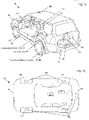
- FIG. 1A sets forth an isometric diagram of a system 100 for estimating a tire operating efficiency and range of an electric vehicle in accordance with the present disclosure.
- FIG. 1B sets forth a top view of the system of FIG. 1A .
- the system of FIG. 1A includes a vehicle 101 equipped with tires 103 that include tire monitoring sensor (TMS) 105.
- TMS tire monitoring sensor
- a TMS is a sensor that is configured to monitor and transmit parameters of a tire.
- a TMS may be coupled to some portion of the tire (e.g., mounted to an inner portion of the tire). In at least one embodiment, the TMS may be coupled to a valve stem of the tire. As will be explained in greater detail below, a TMS may transmit tire parameters to a receiver of a tire pressure monitoring system (TPMS).
- TPMS tire pressure monitoring system
- the vehicle of FIG. 1A further includes a vehicle control system (VCS) 107 that controls various components and systems within a vehicle.
- the VCS 107 includes a plurality of electronic control units (ECUs) that are configured to control one or more vehicle subsystems.
- ECUs electronice control units
- an ECU may be a central control unit or may refer collectively to one or more vehicle subsystem control units, such as an Engine Control Module (ECM), a Powertrain Control Module (PCM), a Transmission Control Module (TCM), a Brake Control Module (BCM), a Central Timing Module (CTM), a General Electronic Module (GEM), or a Suspension Control Module (SCM).
- ECM Engine Control Module
- PCM Powertrain Control Module
- TCM Transmission Control Module
- BCM Brake Control Module
- CTM Central Timing Module
- GEM General Electronic Module
- SCM Suspension Control Module
- the VCS 107 includes a BCM that includes an Antilock Braking System (ABS) and an Electronic Stability Program (ESP).
- the VCS 107 may comprise a Telematics Control Unit (TCU) independent of vehicle-based sensors (e.g., an aftermarket system).
- the vehicle 101 includes a dashboard display screen 140 for displaying messages from the VCS 107.
- the VCS 107 may send a 'low tire pressure' message to a component connected to the dashboard display screen 140.
- the component in response to receiving the 'low tire pressure' message, the component may turn on a 'low tire pressure' indicator that is displayed on the dashboard display screen 140.
- Each TMS 105 may be equipped with a wireless transceiver for bidirectional wireless communication with the VCS 107, as will be described in more detail below.
- the VCS is similarly equipped with a wireless transceiver for bidirectional wireless communication with each of the TMSs 105, as will be described in more detail below.
- the bidirectional wireless communication may be realized by low power communication technology such as Bluetooth Low Energy or other low power bidirectional communication technology that is intended to conserve the amount of energy consumed.
- each TMS 105 may include a unidirectional transmitter configured to transmit signals to the VCS 107.
- each TMS 105 may communicate directly with a smart device (not shown), such as a smart phone, tablet, or diagnostic tool, as will be described in more detail below.
- Each vehicle system may include sensors 113 used to measure and communicate vehicle operating conditions.
- the ABS may include wheel speed sensors on the wheelbase used to measure wheel speed.
- the ESP subsystem may include yaw rate sensors configured to measure the yaw-induced acceleration of the vehicle when the vehicle is maneuvering a curve. Readings from such sensors 113 may be provided to the VCS 107, which may provide parameters based on these readings to the TMS 105.
- the vehicle 101 may further include a transceiver 109 communicatively coupled to the VCS 107 for cellular terrestrial communication, satellite communication, or both.
- Data processing systems useful according to various embodiments of the present disclosure may include additional servers, routers, other devices, and peer-to-peer architectures, not shown in FIGS. 1A and 1B , as will occur to those of skill in the art.
- Networks in such data processing systems may support many data communications protocols, including for example TCP (Transmission Control Protocol), IP (Internet Protocol), Bluetooth protocol, Near Field Communication, Controller Area Network (CAN) protocol, Local Interconnect Network (LIN) protocol, FlexRay protocol, and others as will occur to those of skill in the art.
- Various embodiments of the present disclosure may be implemented on a variety of hardware platforms in addition to those illustrated in FIGS. 1A and 1B .
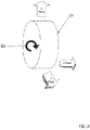
- FIG. 2 illustrates a reference diagram of a tire 103 in accordance with the present disclosure.
- the z-axis of the tire 103 is the direction of radial force during rotation
- the y-axis of the tire is the direction of lateral force during rotation
- the x-axis of the tire 103 is the direction of tangential force during rotation.
- the angular speed of rotation, in radians, is represented by co, and is also referred to herein as wheel speed.
- FIG. 3A illustrates a block diagram of an exemplary tire mounted sensor (TMS) 105 in accordance with the present disclosure.
- the TMS 105 is mounted on, or otherwise coupled to, an internal surface of the tire 103, specifically on the inside of the tread rather than the side wall.
- the flattened portion is known as the tire footprint or, interchangeably, contact patch.
- One or more features of the tire 103, in particular the length of the contact patch may be used, for example, as an indication of the load on the tire 103.
- TMS 105 Electrical signals produced by the TMS 105 can be used to measure the contact patch, in particular its length, as will be described in more detail below. It will be understood that one or more of the tires 103 of the vehicle 101 may each include a TMS 105 for providing one or more target signals in respect of which pulse width measuring is performed.
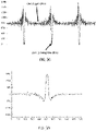
- FIG. 3B illustrates tire features that may be measured using a TMS in accordance with the present disclosure.
- Two tire features that are indicative of tire load are contact patch length and radial displacement, as illustrated in FIG. 3B .
- Radial acceleration is measured using the TMS 105, which may be equipped with an accelerometer, an acceleration sensor, an accelerometric device, a shock sensor, a force sensor, a microelectromechanical systems (MEMS) sensor, or other devices that are similarly responsive to acceleration magnitude and/or to changes in acceleration.
- MEMS microelectromechanical systems
- an accelerometer senses acceleration in the radial plane (z-plane) (see FIG. 2 ). As illustrated in FIG.
- the characteristic of the accelerometric waveform exhibits a centrifugal offset and region where the magnitude momentarily drops to zero during the time when the zone where the sensor is mounted is at tire/ground contact position. This measurement is repeated for rotations of the tire.
- the radial acceleration signal is then conditioned to make processing easier by isolating each strike in the acceleration profile, low-pass filtering the waveform, inverting the waveform, and normalizing the waveform for speed, the result of which is shown in FIG. 3D .
- CPL contact patch length
- PRD peak radial displacement
- Both CPL and PRD are influenced by tire load and pressure, and, accordingly, tires may be characterized by comparing the magnitude of CPL or PRD with varying pressure and load. Characteristic equations may be stored, for example, in the TMS 105 of FIG. 1A or in the vehicle control unit 107 of FIG. 1A .
- CPL may be estimated by measuring the time at which the radial acceleration is returning to and is at zero g. This time is then expressed as a quotient/ratio of the time for a complete rotation, and the CPL is derived from its ratio of the known tire circumference.
- the radial accelerometric signal is integrated twice with respect to time. For load estimation, either of these two methods can be used independently.
- FIG. 4 sets forth a diagram of an exemplary vehicle control system (VCS) 400 for estimating a tire operating efficiency and range of an electric vehicle according to embodiments of the present disclosure.
- the VCS 400 includes a controller 401 coupled to a memory 403.
- the controller 401 is configured to obtain sensor readings related to vehicle operating conditions, as well as data from sources external to the vehicle, and provide configuration parameters to a TMS, such as TMS 600 (see FIG. 6 ).
- the controller may include or implement a microcontroller, an Application Specific Integrated Circuit (ASIC), a general purpose processor, a digital signal processor (DSP), a programmable logic array (PLA) such as a field programmable gate array (FPGA), or other data computation unit in accordance with the present disclosure.
- ASIC Application Specific Integrated Circuit
- DSP digital signal processor
- PDA programmable logic array
- FPGA field programmable gate array
- the sensor readings and data, as well as tire feature data received from the TMS, may be stored in the memory 403.
- the memory 403 may be a non-volatile memory such as flash memory.
- the VCS 400 may obtain vehicle operating condition data, such as sensor readings from sensors on-board the vehicle.
- the VCS 400 includes a TMS transceiver 405 coupled to the controller 401.
- the TMS transceiver 405 is a Bluetooth Low Energy transmitter-receiver.
- the TMS transceiver 405 may be other types of low power radio frequency communication technology that is intended to conserve energy consumed in the TMS.
- the VCS 400 may further include a transceiver 407 for cellular terrestrial communication, satellite communication, or both.
- the VCS 400 may further comprise a controller area network (CAN) interface 409 for communicatively coupling vehicle sensors and devices to the controller 401.
- CAN interface 409 couples a wheel speed sensor 411, a yaw rate sensor 413, an inclination sensor 415, and other sensors 417, to the controller 401.
- the wheel speed sensor 411 measures the rotational angular speed of the wheel, e.g., in radians per second.
- the yaw rate sensor 413 may be used to measure the yaw-induced acceleration of the vehicle, for example, when the vehicle is maneuvering a curve, which will influence the magnitude of loading on each tire.
- the yaw rate sensor 413 may also provide information on the shear forces on the tire where it contacts the road.
- the inclination sensor 415 may detect longitudinal and/or transverse inclination of the vehicle.
- the wheel speed sensor 411, the yaw rate sensor 413, and the inclination sensor 415 transmit respective readings to the controller 401.
- the controller 401 is configured to determine a tire load parameter for a tire based in part on a tire deformation parameter generated by a TMS; determine a coefficient of rolling resistance parameter for the tire based in part on a tire pressure measurement and a linear velocity measurement; and determine, based on the tire load parameter and the coefficient of rolling resistance parameter, a force of rolling resistance parameter for the tire.
- Logic for determining a tire load parameter for a tire based in part on a tire deformation parameter generated by a TMS; determining a coefficient of rolling resistance parameter for the tire based in part on a tire pressure measurement and a linear velocity measurement; and determining, based on the tire load parameter and the coefficient of rolling resistance parameter, a force of rolling resistance parameter for the tire may be embedded in logic blocks of the controller 401 or stored as a set of executable instructions in the memory of the VCS 400.
- the controller is further configured to determine, based on the force of rolling resistance parameter, an energy consumption parameter for the tire.
- the controller is further configured to estimate, based on at least the energy consumption parameter and a battery charge value, a range for an electric vehicle.
- the controller is further configured to signal an alert based on the energy consumption parameter for the tire.
- the controller is configured to receive one or more tire parameter related to rolling resistance from a TMS, for example, over a wireless bidirectional communications link such as a Bluetooth protocol link.
- the one or more parameters can include a force of rolling resistance parameter, an energy consumption parameter based on the force of rolling resistance, a tire load parameter useful in calculating the force of rolling resistance, and/or a coefficient of rolling resistance parameter.
- the one or more parameters may also include other parameters that contribute to the force of rolling resistance, such as a tire deformation parameter (e.g., contact patch length or peak radial displacement), a tire pressure parameter, a tire stiffness parameter, a tire velocity parameter, and/or a tire dimension parameter (e.g., radius, diameter, or circumference).
- the controller may be further configured to receive identification information such as a TMS identifier or tire identification data.
- the controller 401 may request the rolling resistance parameters by polling the TMS or sending a message requesting the rolling resistance parameters.
- the controller 401 may also prompt the TMS to provide the data in response to a wake-up signal.
- the controller 401 may receive the data from the TMS as part of an unsolicited broadcast of rolling resistance parameters.
- the controller may detect a reporting event that prompts the controller 401 to request rolling resistance parameters from the TMS.
- the event may be the detection of a change in vehicle or tire operating characteristics, such as a change in speed or tire pressure.
- the event may also be the detection that a particular amount of time has passed or that a particular distance has been traveled since rolling resistance parameters were last received.
- the controller 401 may first establish that the vehicle is operating in a steady state condition before requesting the rolling resistance parameters from the TMS.
- the steady state condition be that vehicle speed and acceleration are nearly constant, that a vehicle speed threshold has been met, that the vehicle is not maneuvering a corner, that the vehicle is not at an incline, and/or that tire temperature and pressure are constant.
- the controller 401 may poll the TMS for the rolling resistance parameters.
- the controller 401 is configured to identify an efficiency parameter indicative of at least one of an energy consumption for a tire and an operating efficiency of the tire. In some implementations, the controller 401 identifies the efficiency parameter of a tire by receiving at least one of an energy consumption parameter and a tire operating efficiency parameter from the TMS of that tire along with a TMS identifier. In other implementations, the controller 401 identifies the efficiency parameter by calculating the energy consumption, for example, using Equation 1. In such an example, the controller 401 calculates the energy consumption of the tire as the product of a force of rolling resistance on the tire and a distance travelled by the tire.
- the distance travelled by the tire may be based on a distance parameter received from the TMS, based on a vehicle speed derived from vehicle-based sensors such as a wheel speed sensor, or based on GPS doppler data obtained from the cellular/satellite transceiver 407 or from another position tracking data source.
- the controller 401 determines the efficiency parameter by calculating a tire operating efficiency as a ratio of an expected tire operating parameters to actual tire operating parameter values that are measured or estimated as discussed above.
- the reference values for calculating tire efficiency may be obtained from the TMS or retrieved from a remote server or cloud-based information service using tire identification data received from the TMS
- the controller 401 is configured to identify a force of rolling resistance parameter for each tire. In some implementations, the controller 401 identifies the force of rolling resistance parameter of a tire by receiving the force of rolling resistance parameter from the TMS of that tire along with a TMS identifier. In other implementations, the controller 401 identifies the force of rolling resistance parameter of a tire by calculating the force of rolling resistance, for example, using Equation 2. In such an example, the controller 401 calculates the product of tire load and a coefficient of rolling resistance.
- the controller 401 is configured to identify a tire load parameter for each tire for calculating the force of rolling resistance. In some implementations, the controller 401 identifies the tire load parameter of a tire by receiving the tire load parameter from the TMS of that tire along with a TMS identifier. In other implementations, the controller 401 identifies the tire load parameter of a tire by receiving the tire load parameter from one or more tire load sensors mounted to the vehicle. In yet other implementations, the controller 401 identifies the tire load parameter of a tire by calculating a driving tire load using a tire load characteristic equation.
- the controller 401 calculates the tire load based on inputs to the tire load characteristic equation including, for example, a tire deformation parameter (e.g., contact patch length or peak radial displacement), a tire stiffness parameter, a tire pressure parameter, a tire temperature parameter, and tire dimension data (e.g., radius, diameter, or circumference).
- the tire deformation parameter is received from the TMS.
- the tire pressure parameter may also be received from the TMS, or may be received from a valve-mounted tire pressure monitoring sensor.
- the tire temperature parameter may also be received from the TMS, or may be received from a valve-mounted tire pressure monitoring sensor.
- the tire dimension data may also be received from the TMS (e.g., programmed into the TMS at manufacture), or may be retrieved from a remote server using tire identification data received from the TMS.
- the tire stiffness parameter may also be received from the TMS (e.g., programmed into the TMS at manufacture), or may be retrieved from a remote server using tire identification data received from the TMS.
- the load on the tire may be further determined based on a load error factor to compensate for a tire load parameter derived from a tire load characteristic equation.
- the load error factor may be calculated using one or more other characteristic equations based on drive time, number of tire rotations since vehicle start or a lifetime of the tire, the temperature of the tire, etc. The load error factor may then be applied to the previously derived tire load parameter to determine a more accurately calculated load value.
- the controller 401 is configured to estimate a tire load parameter based on an effective rolling radius of the tire.
- the controller 401 may be configured to calculate the rolling radius of the tire as a ratio of the linear velocity of the wheel center to the angular velocity of the wheel.
- the linear velocity of the wheel center may be based on Global Positioning System (GPS) doppler data.
- the angular velocity of the wheel may be based on data from a wheel speed sensor 411 or a TMS.
- the wheel speed sensor 411 may be a component of an Antilock Braking System (ABS).
- ABS Antilock Braking System
- the controller 401 may then calculate the rolling radius of the tire based on the data indicating the linear velocity of the wheel and the angular velocity of the wheel.
- the difference between a static radius of the tire and the rolling radius represents the peak radial displacement.
- the static radius of the tire may be obtained from the TMS, from a remote server using tire identification data obtained from the TMS, or through previous measurements of the tire radius or circumference based on a rotational time period of the tire and linear velocity, with or without compensation for tread wear.
- the controller 401 is configured to identify a coefficient of rolling resistance parameter for each tire, which is useful in calculating the force of rolling resistance. In some implementations, the controller 401 identifies the coefficient of rolling resistance parameter of a tire by receiving the coefficient of rolling resistance parameter from the TMS of that tire along with a TMS identifier. In other implementations, the controller 401 identifies the coefficient of rolling resistance parameter of a tire by calculating a driving coefficient of rolling resistance using a characteristic equation such as, for example, Equation 3. In these implementations, the coefficient of rolling resistance is calculated using the characteristic equation with linear velocity of the tire and tire pressure as inputs. In some examples, the tire pressure parameter may be received from the TMS, or may be received from a valve-mounted tire pressure monitoring sensor.
- the linear velocity parameter may also be received from the TMS, or may be determined from vehicle-based sensors, or may be based on GPS doppler data obtained from the cellular/satellite transceiver 407 or from another position tracking data source.
- the VCS 400 stores multiple characteristic equations for the tire corresponding to different road conditions.
- the controller 401 may use one characteristic equation for dry surfaces and another for wet surfaces (e.g., based on operation of the windshield wipers).
- the VCS 400 retrieves one or more characteristic equations for the coefficient of rolling resistance of the tire from a remote server based on tire identification data received from the TMS.
- the controller 401 is further configured to estimate a range for the electric vehicle based in part on the energy consumption of the tires due to rolling resistance.
- the force of rolling resistance can be combined with measurements or estimates for vehicle drag and internal friction to determine a total energy utilization required under the instant operating conditions.
- the VCS 400 receives data from the battery pack or individual cells indicating a stored charge in the battery cells. Based on the amount of energy expended to travel a fixed distance under the instance operating condition and based on the amount of available energy in the battery pack, a driving range can be determined by the VCS 400.
- the VCS 400 is further configured to alert the driver when a tire is consuming more energy than other tires or is consuming more than a threshold amount of energy.
- the VCS 400 may illuminate a symbol on the instrument panel, sound an audible alarm, display a warning on the vehicle display, or send a message to a user through a connected smart device, or a messaging platform such as text message, email, or the like.
- the controller 401 is configured to suggest changing the tire pressure/load to enhance tire/vehicle efficiency.
- the controller 401 may provide information on a vehicle display, or send a message to a user through a connected smart device or messaging platform, indicating the efficiency can be improved by changing the tire pressure or tire load.
- the controller 401 is configured to determine a tire and/or vehicle operational efficiency rating.
- the controller 401 may provide an efficiency rating on a vehicle display or in a message sent to a user through a connected smart device or messaging platform.
- FIG. 5A sets forth a diagram of an embodiment of a Telematics Control Unit (TCU) 500 (e.g., an aftermarket system not directly coupled to vehicle-based sensors).
- TCU 500 of FIG. 5A includes a controller 501, memory 503, and TMS transceiver 505 performing similar functions as described above with respect to the VCS 400 Figure 4 .
- the TCU 500 also includes a Global Positioning System (GPS) receiver 557 configured to communicate with one or more GPS satellites to determine a vehicle location, speed, direction of movement, etc.
- GPS Global Positioning System
- the TCU 500 also includes an inertial measurement unit (IMU) 559 configured to measures a vehicle's specific force, angular rate, and/or orientation using a combination of accelerometers, gyroscopes, and/or magnetometers.
- IMU inertial measurement unit
- the TCU 500 also includes an on-board diagnostics (OBD) interface 561 for coupling the TCU 500 to one or more on-board diagnostic devices of a vehicle.
- OBD on-board diagnostics
- the TCU 500 may receive power via a power interface 563 couplable to a vehicle power bus.
- the controller 501 of the TCU 500 may be configured like the controller 401 of the VCS 400 of FIG. 4 to determine rolling resistance parameters, even though the TCU 500 may not have access to other vehicle subsystems through the CAN interface 409 of the VCS 400.
- the controller 501 of the TCU 500 may also be configured to receive one or more tire parameters related to rolling resistance from a TMS.
- the one or more parameters may include one or more of a tire pressure parameter, a linear velocity parameter, a tire deformation parameter, a tire stiffness parameter, a tire load parameter, a coefficient of rolling resistance parameter, a force of rolling resistance parameter, and an efficiency parameter indicative of at least one of an energy consumption for the tire and an operating efficiency of the tire.
- the controller 501 may also be configured to receive tire characteristics data from the TMS, such as one or more of tire dimension data, tire mass data, slip angle, tire identification data, and TMS identifier data.
- the controller 501 may also be configured to retrieve tire characteristics data from a remote server or cloud-based information service using tire identification.
- the controller 501 may be configured to determine a tire load parameter for a tire based in part on a tire deformation parameter generated by a TMS; determine a coefficient of rolling resistance parameter for the tire based in part on a tire pressure measurement and a linear velocity measurement; and determine, based on the tire load parameter and the coefficient of rolling resistance parameter, a force of rolling resistance parameter for the tire.
- the controller 501 is further configured to determine, based on the force of rolling resistance parameter, an energy consumption parameter for the tire.
- the controller 501 is further configured to estimate, based on at least the energy consumption parameter and a battery charge value, a range for an electric vehicle.
- the controller 501 is further configured to signal an alert based on the energy consumption parameter for the tire.
- the controller 501 is configured to suggest changing the tire pressure/load to enhance tire/vehicle efficiency.
- the controller 501 may provide information on a vehicle display, or send a message to a user through a connected smart device or messaging platform, indicating the efficiency can be improved by changing the tire pressure or tire load.
- the controller 501 is configured to determine a tire and/or vehicle operational efficiency rating.
- the controller 501 may provide an efficiency rating on a vehicle display or in a message sent to a user through a connected smart device or messaging platform.
- the controller 501 may include or implement a processor configured to execute stored computer-executable instructions or an ASIC configured with embedded logic.
- FIG. 5B sets forth a diagram of an embodiment of a smart device 580 (e.g., a smart phone or a tablet physically detached from the vehicle).
- the smart device 580 of FIG. 5B includes a controller 581, memory 583, and a transceiver 590 (e.g., a Bluetooth transceiver).
- the transceiver 590 is configured to communicate with the TMS and/or the VCS.
- the smart device 580 also includes a Global Positioning System (GPS) receiver 591 configured to communicate with one or more GPS satellites in order to determine a vehicle location, speed, direction of movement, etc.
- GPS Global Positioning System
- the smart device 580 also includes an inertial measurement unit (IMU) 589 configured to measures the device's specific force, angular rate, and/or orientation using a combination of accelerometers, gyroscopes, and/or magnetometers.
- IMU inertial measurement unit
- the smart device 580 also includes a display 598 that displays, for example, an energy consumption value associated with a tire.
- the smart device 580 may receive power from a power interface 599 couplable to a battery or to a vehicle power source.
- the controller 581 of the smart device 580 may be configured like the controller 401 of the VCS 400 of FIG. 4 to determine rolling resistance parameters and/or an energy expenditure of a tire, as well as a vehicle range, even though the smart device 580 may not have access to vehicle subsystems through the CAN interface 409 of the VCS 400.
- the controller 581 of the smart device 580 may also be configured to receive one or more tire parameters related to rolling resistance from a TMS.
- the one or more parameters may include one or more of a tire pressure parameter, a linear velocity parameter, a tire deformation parameter, a tire stiffness parameter, a tire load parameter, a coefficient of rolling resistance parameter, a force of rolling resistance parameter, and an energy consumption parameter.
- the controller 581 may also be configured to receive tire characteristics data from the TMS, such as one or more of tire dimension data, tire mass data, slip angle, tire identification data, and TMS identifier data.
- the controller 581 may also be configured to retrieve tire characteristics data from a remote server or cloud-based information service using tire identification.
- the memory 583 stores an application 584 embodied in computer-readable instructions that, when executed by the controller 581 cause the controller 581 to determine a tire load parameter for a tire based in part on a tire deformation parameter generated by a TMS; determine a coefficient of rolling resistance parameter for the tire based in part on a tire pressure measurement and a linear velocity measurement; and determine, based on the tire load parameter and the coefficient of rolling resistance parameter, a force of rolling resistance parameter for the tire.
- the controller 581 is further configured to determine, based on the force of rolling resistance parameter, an efficiency parameter indicative of at least one of energy consumption for the tire and an operating efficiency of the tire.
- the controller 581 is further configured to estimate, based on at least the energy consumption parameter and a battery charge value, a range for an electric vehicle. In some examples, the controller 581 is further configured to signal an alert based on the energy consumption parameter for the tire. In some implementations, the controller 581 is configured to suggest changing the tire pressure/load to enhance tire/vehicle efficiency. For example, the controller 581 may provide information on a smart device display, or send a message to a user through a messaging platform, indicating the efficiency can be improved by changing the tire pressure or tire load. In some implementations, the controller 581 is configured to determine a tire and/or vehicle operational efficiency rating. For example, the controller 581 may provide an efficiency rating on a smart device display or in a message sent to a user through a messaging platform.
- FIG. 6 sets forth a diagram of an exemplary tire monitoring sensor (TMS) 600 for determining tread depth according to embodiments of the present disclosure.
- the TMS 600 includes a controller 601.
- the controller 601 may include or implement a processor, an Application Specific Integrated Circuit (ASIC), a digital signal processor (DSP), a programmable logic array (PLA) such as a field programmable gate array (FPGA), or other data computation unit in accordance with the present disclosure.
- ASIC Application Specific Integrated Circuit
- DSP digital signal processor
- PDA programmable logic array
- FPGA field programmable gate array
- the TMS 600 of FIG. 6 also includes a memory 603 coupled to the controller 601.
- the memory may store signal capture parameters 621 such as the particular number of revolutions to measure the rotational time period, which may be determined by the controller 601, programmed into the memory 603, or received from the VCS 400 or the TCU 500.
- the memory 603 may store a sampling rates table 622 of sampling rates at which the ADC 611 sampled accelerometric signals data from the accelerometer 607.
- the controller 601 may configure the ADC 611 in accordance with a stored sampling rate.
- the memory 603 may also store a windowing function table 623 of windowing functions for identifying a rotational period of the tire from accelerometric data.
- the memory 603 may also store a filter table 624 of filter frequency bands with which to filter an accelerometric waveform.
- the memory 603 may also store accelerometric data 625, including a raw digital signal sampled from the accelerometer 607 by the ADC 611 and a processed accelerometric waveform processed by the controller 601.
- the memory 603 may also store tire data 626, such as a TMS identifier, a tire identifier (e.g., manufacturer make and model), manufacturer specifications for tire dimension (e.g., radius, circumference, width, aspect ratio, tread depth), a tire stiffness parameter, a tire mass parameter, manufacturer data relating to the tire's coefficient of rolling resistance, and the like.
- the memory 603 may also store reference data 627 such as a reference circumference, a reference radius, and/or a reference tread depth received from the VCS 400 or the TCU 500 after an initial measurement of the tire when the tire is in a substantially original condition (i.e., when the tire is new).
- reference data 627 such as a reference circumference, a reference radius, and/or a reference tread depth received from the VCS 400 or the TCU 500 after an initial measurement of the tire when the tire is in a substantially original condition (i.e., when the tire is new).
- the TMS 600 of FIG. 6 includes a transceiver 605 coupled to the controller 601.
- the transceiver 605 is a Bluetooth Low Energy transmitter-receiver.
- the transceiver 605 may be other types of low energy bidirectional communication technology that is intended to conserve energy consumed in the TMS 600.
- the TMS 600 may transmit tire parameters related to rolling resistance or other tire parameters to the VCS 400 or TCU 500 via the transceiver 605.
- the TMS 600 includes a unidirectional transmitter configured to transmit data to the VCS 400 or the TCU 500.
- the accelerometer 607 of FIG. 6 may also be an acceleration sensor, an accelerometric device, a shock sensor, a force sensor, a microelectromechanical systems (MEMs) sensor, or other device that is similarly responsive to acceleration magnitude and/or to changes in acceleration, such that a tire revolution may be determined from the time between detected ground strike events.
- an accelerometer senses acceleration in the radial plane (z-plane), lateral plane (y-plane), and/or tangential plane (x-plane), and outputs an electric pulse signal responsive to sensed acceleration, including but not limited to signals indicative of ground strikes.
- the accelerometer 607 is configurable with an accelerometer range, a wheel speed parameter, or other vehicle parameter provided by the VCS 400.
- g-offset can be determined via wheel speed sensor or another vehicle parameter and used to capture and process signals faster.
- Accelerometers may have a selectable range of forces they can measure. These ranges can vary from ⁇ 1g up to ⁇ 700g.
- An example range of an accelerometer is ⁇ 200g.
- the accelerometer range may be configured based on wheel speed, for example, ⁇ 150g at a low speed, ⁇ 250g at a medium speed, and ⁇ 500g at a high speed. Typically, the smaller the range, the more sensitive the readings will be from the accelerometer.
- the TMS 600 of FIG. 6 also includes an analog to digital converter (ADC) 611 that receives the electric pulse signals from the accelerometer 607 and sampled accelerometric signals them according to a sampling rate.
- ADC analog to digital converter
- the ADC 611 converts the raw analog signals received from the accelerometer 607 into a raw digital signal that is suitable for digital signal processing.
- the TMS 600 of FIG. 6 also includes a battery 609 connected to a power bus (not shown) to power the transceiver 605, the controller 601, the ADC 611, the accelerometer 607, and the memory 603.
- the TMS 600 may be powered by other sources alternative to or in addition to the battery 609, such as an energy harvester or other power source.
- the TMS 600 may be configured to measure, estimate, or store a number of tire parameters related to rolling resistance, such as a tire velocity parameter, a tire pressure parameter, tire dimension data, a tire stiffness parameter, a slip angle parameter, a tire deformation parameter, a coefficient of rolling resistance parameter, a force of rolling resistance parameter. These parameters may be useful in determining the energy expenditure of the tire due to rolling resistance.
- static parameters such as tire dimension data, one or more tire stiffness coefficients, and/or a slip angle parameter are programmed int the TMS 600 (e.g., into the memory 603 of the TMS 600) at manufacture or installation of the TMS.
- dynamic parameters such as tire velocity, tire pressure, or tire deformation, may be measured or estimated based on TMS accelerometers and sensors.
- the controller 601 of the TMS 600 is configured to transmit one or more parameters related to rolling resistance to another component of a tire monitoring system, such as a VCS (e.g., the VCS 400 of FIG. 4 ), a TCU (e.g., the TCU 500 of FIG. 5A ), and a smart device (e.g., the smart device 580 of FIG. 5B ) over a wireless bidirectional communications link.
- VCS e.g., the VCS 400 of FIG. 4
- a TCU e.g., the TCU 500 of FIG. 5A
- a smart device e.g., the smart device 580 of FIG. 5B
- the controller 601 of the TMS 600 is configured to determine a linear tire velocity parameter for the tire.
- the controller 601 calculates the velocity parameter based on the angular velocity of the tire using data from the accelerometer 607.
- an accelerometric waveform is generated from raw accelerometric data, and the angular velocity can be expressed as the number of sampled accelerometric signals between like accelerometric waveform peaks divided by the sampling frequency.
- the controller 601 can determine the number of sampled accelerometric signals between two entry area peaks and divide the number of sampled accelerometric signals by the sampling frequency to determine the angular velocity.
- the controller 601 can determine the linear tire velocity parameter as the product of the angular velocity of the tire and the radius of the tire (e.g., identified from tire dimension data stored in the memory 603 of the TMS 600 or received from the VCS 400).
- the TMS 600 transmits the linear tire velocity parameter to another component (e.g., the VCS 400, TCU 500, or smart device 580) using the above-described communications links.
- the linear tire velocity parameter may be useful to another component that calculates other tire parameters related to rolling resistance, and thus the energy expenditure of the tire.
- the controller 601 of the TMS 600 is configured to determine a tire pressure parameter and a tire temperature parameter by measuring tire pressure and tire temperature.
- the TMS 600 is configured with an integrated pressure sensor and an integrated temperature sensor.
- the TMS 600 may act as a tire pressure monitoring system (TPMS) sensor that is configured to measure tire pressure and tire temperature a provide a tire pressure parameter and tire temperature parameters to a tire pressure monitoring system, the VCS 400, the TCU 500, or the smart device 580.
- TPMS tire pressure monitoring system
- the TMS 600 receives a tire pressure parameter and a tire temperature parameter from communicatively coupled sensors such as a valve-mounted TPMS sensor.
- the TMS 600 transmits tire pressure parameter to another component (e.g., the VCS 400, TCU 500, or smart device 580) using the above-described communications links.
- the tire pressure parameter may be useful to another component that calculates other tire parameters related to rolling resistance, and thus the energy expenditure of the tire.
- the controller 601 of the TMS 600 is configured to determine a tire deformation parameter.
- controller 601 of the TMS 600 measures a value for tire deformation such as peak radial displacement or contact patch length using accelerometric data from one or more accelerometers (e.g., a radial accelerometer) of the TMS.
- a value for tire deformation such as peak radial displacement or contact patch length
- contact patch length may be estimated by measuring the time at which the radial acceleration is returning to and is at zero g. This time is then expressed as a quotient/ratio of the time for a complete rotation, and the contact patch length is derived from its ratio of the known tire circumference.
- tire dimension data such as radius, diameter, or circumference may be programmed into a memory of the TMS 600 at manufacture or installation.
- the radial accelerometric signal may be integrated twice with respect to time.
- the peak radial displacement may be determined from the effective rolling radius compared to a reference radius (e.g., programmed into the TMS at manufacture or installation), where the effective rolling radius is expressed as a quotient of linear velocity and angular velocity.
- linear velocity of the tire may be determined from GPS doppler data and provided to the TMS 600 by a VCS, TCU or smart device through a bidirectional communications link.
- the TMS 600 transmits a tire deformation parameter (i.e., a peak radial displacement parameter or a contact patch length parameter) to another component (e.g., the VCS 400, TCU 500, or the smart device 580) using the above-described communications links.
- a tire deformation parameter i.e., a peak radial displacement parameter or a contact patch length parameter
- the tire deformation parameter may be useful to another component that calculates other tire parameters related to rolling resistance, and thus the energy expenditure of the tire.
- the controller 601 of the TMS 600 is configured to determine a tire load parameter based in part on a tire deformation parameter generated by TMS; determine a coefficient of rolling resistance based in part on a tire pressure measurement and a tire velocity measurement; and determine, based on the tire load parameter and the coefficient of rolling resistance, a force of rolling resistance parameter.
- the controller 601 may include a processor configured to carry out these steps through the execution of processor-executable instructions stored in the memory 603 of the TMS.
- the controller 601 may include an integrated circuit embedded with logic blocks configured to carry out these steps.
- the controller 601 of the TMS 600 is configured to determine a tire load parameter based on a tire deformation parameter, such as a peak radial displacement and/or contact patch length, as discussed above.
- the controller 601 is configured to calculate a tire load parameter based on a deformation of the tire at a road contact surface, one or more stiffness coefficients, and one or more tire characteristics such a tire pressure.
- a characteristic equation may be used to calculate a tire load parameter by accepting, as inputs to the equation, a measured radial deformation (e.g., peak radial displacement), the stiffness coefficients, and the one or more tire characteristics.
- the one or more tire characteristics may include a temperature of the tire, a pressure of the tire, and/or a velocity of the tire, any of which may be determined by the TMS 600 as discussed above or may be received from other tire monitoring system components such as the VCS 400.
- the one or more stiffness coefficients may be stored in the TMS 600 at manufacture or TMS installation in the tire, or may be received from the VCS 400 or other component, as described above.
- the TMS 600 transmits the tire load parameter to another component (e.g., VCS 400, TCU 500, or smart device 580) using the above-described communications links.
- the tire load parameter may be useful to another component that calculates other tire parameters related to rolling resistance, and thus the energy expenditure of the tire and/or tire operating efficiency.
- the controller 601 is configured to calculate the coefficient of rolling resistance using a characteristic equation, such as Equation 3 above. In these embodiments, the controller 601 supplies a tire pressure parameter as an input to the characteristic equation for the coefficient of rolling resistance. In some examples, the controller 601 identifies a tire pressure parameter measured by the TMS 600 itself, as discussed above. In other examples, the controller 601 identifies a tire pressure parameter that is received from the VCS 400 as measured by other sensors or received directly from other sensors (e.g., valve-mounted tire pressure sensors, etc.). In these implementations, the controller 601 supplies a velocity parameter as an input to the characteristic equation for the coefficient of rolling resistance.
- a characteristic equation such as Equation 3 above.
- the controller 601 utilizes a velocity parameter that is calculated by the TMS 600 itself, as discussed above.
- the TMS 600 receives a velocity parameter from another component such as the VCS 400, the TCU 500, or the smart device 580.
- the VCS 400, TCU 500, or smart device 580 may determine the linear velocity of the wheel center may be based on Global Positioning System (GPS) doppler data and supply a velocity parameter based on the measured linear velocity to the TMS 600.
- GPS Global Positioning System
- the VCS 400 may determine the angular velocity of the wheel based on data from a wheel speed sensor 411 and supply a velocity parameter to the TMS 600.
- the characteristic equation for the coefficient of rolling resistance is stored in the memory 603 of the TMS 600 at manufacture or is later received from the VCS 400.
- the memory 603 stores multiple characteristic equations for the coefficient of rolling resistance, where different characteristic equations correspond to different road conditions.
- the VCS 400 supplies the TMS 600 with information relating to the current road conditions.
- the TMS 600 transmits a coefficient of rolling resistance parameter to another component (e.g., VCS 400, TCU 500, or smart device 580) using the above-described communications links.
- the coefficient of rolling resistance parameter may be useful to another component that calculates other tire parameters related to rolling resistance.
- the controller 601 is configured to determine a force of rolling resistance parameter. In these embodiments, the controller 601 calculates the force of rolling resistance, for example, using Equation 2 above. In these implementations, the controller 601 calculates the product of the tire load parameter and the coefficient of rolling resistance parameter. In some embodiments, the TMS 600 transmits a force of rolling resistance parameter to another component (e.g., the VCS 400, TCU 500, or smart device 580) using the above-described communications links. The force of rolling resistance parameter may be useful to another component that calculates an efficiency parameter.
- another component e.g., the VCS 400, TCU 500, or smart device 580
- the controller 601 is configured to determine an efficiency parameter indicative of at least one of an energy consumption parameter and a tire operating efficiency parameter based on the force of rolling resistance. In these embodiments, the controller 601 may determine an efficiency parameter by calculating the energy expended, or work performed, by the tire by calculating the product of the force of rolling resistance and a linear distance traveled as demonstrated in Equation 1 above. As discussed above, the linear distance traveled may be determined from the circumference of the tire and a particular number of revolutions. In some embodiments, the controller 601 may determine an efficiency parameter by calculating a tire operation efficiency. In some examples, to determine tire operating efficiency, the TMS utilizes reference values for tire operating parameters to determine a tire operating efficiency based on measured or estimated values for tire operating or rolling resistance parameters.
- the TMS 600 transmits an efficiency parameter such as an energy expenditure parameter or tire operating efficiency parameter to another component (e.g., VCS 400, TCU 500, or smart device 580) using the above-described communications links.
- the energy expenditure parameter and/or tire operating efficiency parameter may be useful to another component that calculates an electric vehicle range.
- the TMS 600 is configured to provide some or all of the tire parameters related to rolling resistance discussed above to another component such as the VCS 400, the TCU 500, or the smart device 580.
- the TMS 600 provides the force of rolling resistance parameter to another component, which determines an efficiency parameter such as an energy expenditure or tire operating efficiency parameter based on the force of rolling resistance parameter.
- the TMS 600 provides the coefficient of rolling resistance parameter and the tire load parameter to another component, which determines the force of rolling resistance based on the coefficient of rolling resistance parameter and the tire load parameter provided by the TMS 600, and then determines the energy expenditure or tire operating efficiency.
- the TMS 600 provides the tire load parameter to another component, which calculates the coefficient of rolling resistance based on tire pressure and velocity parameters obtained from other sensors.
- the TMS 600 may provide other tire parameters such as a TMS identifier, a tire identifier (e.g., manufacturer make and model), manufacturer specifications for tire dimension (e.g., radius, circumference, width, aspect ratio, tread depth), a tire stiffness parameter, a tire mass parameter, a slip angle parameter, and the like that may be stored in the memory 603 of the TMS 600.
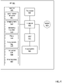
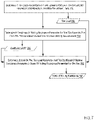
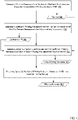
- FIG. 7 sets forth a flow chart illustrating an exemplary method for estimating a tire operating efficiency and range of an electric vehicle according to embodiments of the present disclosure that includes determining 702 a tire load parameter 703 for a tire based in part on a tire deformation parameter generated by a tire mounted sensor (TMS).
- determining 702 the tire load parameter 703 may be carried out by a TMS (e.g., the TMS 600 of FIG. 6 ), by a vehicle-based control unit (e.g., the VCS 400 of FIG. 4 or the TCU 500 of FIG. 5A ), or by a portable electronic device (e.g., the smart device 580 of FIG. 5B ).
- a TMS measures a value for tire deformation such as peak radial displacement or contact patch length using accelerometric data from one or more accelerometers (e.g., a radial accelerometer) of the TMS.
- accelerometers e.g., a radial accelerometer
- contact patch length may be estimated by measuring the time at which the radial acceleration is returning to and is at zero g. This time is then expressed as a quotient/ratio of the time for a complete rotation, and the contact patch length is derived from its ratio of the known tire circumference.
- tire dimension data such as radius, diameter, or circumference may be programmed into a memory of the TMS at manufacture or installation.
- the radial accelerometric signal may be integrated twice with respect to time.
- the peak radial displacement may be determined from the effective rolling radius compared to a reference radius (e.g., programmed into the TMS at manufacture or installation), where the effective rolling radius is expressed as a quotient of linear velocity and angular velocity.
- linear velocity of the tire may be determined from GPS doppler data and provided to the TMS by a VCS, TCU or smart device through a wireless bidirectional communications link.
- the linear velocity may be determined by determining a rotational time period (e.g., a time between road strikes based on accelerometric waveforms) and dividing the circumference of the tire (e.g., programmed into the TMS at manufacture or installation) by the rotational time period.
- the circumference of the tire may be compensated for tread wear using well-known tread wear estimation techniques. For tire load estimation, determining a tire load from contact path length and determining a tire load from peak radial displacement may be employed independently.
- the tire load parameter 703 may be calculated using a characteristic equation for tire load as a function of tire deformation (i.e., contact patch length or peak radial displacement), or determined from a lookup table for tire load corresponding to an identified contact tire deformation value.
- a characteristic equation may be stored in a memory or retrieved from a remote server or cloud-based information service using tire identification data stored on the TMS.
- tire load may be compensated by a measured tire pressure using one or more tire stiffness coefficients.
- tire load is estimated by determining the degree of tire deformation and proportioning the degree of deformation due to measure tire pressure and an amount due to actual tire load.
- the tire load coefficient may be determined as the product of the tire stiffness coefficient and the amount of tire deformation.
- a characteristic equation for tire load as a function of tire deformation, tire pressure, and a stiffness coefficient may be stored in a memory or retrieved from a remote server or cloud-based information service using tire identification data stored on the TMS.
- the tire load parameter 703 may be further determined based on a load error factor to compensate for a tire load value derived from a characteristic equation.
- the load error factor may be calculated using one or more other characteristic equations based on drive time, number of tire rotations since vehicle start or a lifetime of the tire, the temperature of the tire, etc. The load error factor may then be applied to the previously derived tire load parameter 703 to determine a more accurately calculated tire load parameter 703.
- the TMS determines 702 the tire load parameter 703.
- a characteristic equation or lookup table for tire load based on tire deformation may be programmed into the memory of the TMS at manufacture or installation.
- the TMS determines a tire deformation parameter based on peak radial displacement or contact patch length.
- one or more tire stiffness coefficients may be programmed into the memory of the TMS at manufacture or installation.
- the TMS identifies a tire pressure measurement using an integrated pressure sensor.
- the TMS obtains a tire pressure measurement from a communicatively coupled tire pressure sensor such as a valve-mounted TPMS.
- the TMS may transmit the determined tire load parameter 703 to a vehicle-based control unit (e.g., the VCS 400 of FIG. 4 or the TCU 500 of FIG. 5A ) or a portable electronic device (e.g., the smart device 580 of FIG. 5B ) using a wireless bidirectional communications link such as a Bluetooth communications protocol link.
- the TMS may transmit the tire load parameter 703 in response to a request or polling message, in response to a detected event, or at some predetermined time interval.
- a VCS determines 702 the tire load parameter 703. In some examples, the VCS determines 702 the tire load parameter by identifying a tire load parameter 703 received from the TMS with TMS identification data. In other examples, the VCS determines 702 the tire load parameter 703 by calculating the tire load parameter 703. In these examples, the VCS receives a tire deformation parameter (e.g., contact patch length or peak radial displacement) from the TMS. In some examples, the VCS receives a characteristic equation and/or tire stiffness coefficient for estimating tire load from the TMS.
- a tire deformation parameter e.g., contact patch length or peak radial displacement
- the VCS obtains the characteristic equation and/or tire stiffness coefficient for estimating tire load from a remote server or cloud-based information service using tire identification data provided by and stored on the TMS.
- the VCS receives a tire pressure measurement for estimating tire load from the TMS.
- the VCS receives a tire pressure measurement for estimating tire load from another sensor such as a valve-mounted TPMS.
- the VCS may receive the tire deformation parameter, characteristic equations, tire stiffness coefficient, and/or tire pressure from the TMS using a wireless bidirectional communications link such as a Bluetooth communications protocol link.
- a TCU determines 702 the tire load parameter 703. In some examples, the TCU determines 702 the tire load parameter by identifying a tire load parameter 703 received from the TMS with TMS identification data. In other examples, the TCU determines 702 the tire load parameter 703 by calculating the tire load parameter 703. In these examples, the TCU receives a tire deformation parameter (e.g., contact patch length or peak radial displacement) from the TMS. In some examples, the TCU receives a characteristic equation and/or tire stiffness coefficient for estimating tire load from the TMS.
- a tire deformation parameter e.g., contact patch length or peak radial displacement
- the TCU obtains the characteristic equation and/or tire stiffness coefficient for estimating tire load from a remote server or cloud-based information service using tire identification data provided by and stored on the TMS.
- the TCU receives a tire pressure measurement for estimating tire load from the TMS.
- the TCU receives a tire pressure measurement for estimating tire load from another sensor such as a valve-mounted TPMS.
- the TCU may receive the tire deformation parameter, characteristic equations, tire stiffness coefficient, and/or tire pressure from the TMS using a bidirectional communications link such as a Bluetooth communications protocol link.
- a smart device determines 702 the tire load parameter 703. In some examples, the smart device determines 702 the tire load parameter by identifying a tire load parameter 703 received from the TMS with TMS identification data. In other examples, the smart device determines 702 the tire load parameter 703 by calculating the tire load parameter 703. In these examples, the smart device receives a tire deformation parameter (e.g., contact patch length or peak radial displacement) from the TMS. In some examples, the smart device receives a characteristic equation and/or tire stiffness coefficient for estimating tire load from the TMS.
- a tire deformation parameter e.g., contact patch length or peak radial displacement
- the smart device obtains the characteristic equation and/or tire stiffness coefficient for estimating tire load from a remote server or cloud-based information service using tire identification data provided by and stored on the TMS.
- the smart device receives a tire pressure measurement for estimating tire load from the TMS.
- the smart device receives a tire pressure measurement for estimating tire load from another sensor such as a valve-mounted TPMS.
- the smart device may receive the tire deformation parameter, characteristic equations, tire stiffness coefficient, and/or tire pressure from the TMS using a bidirectional communications link such as a Bluetooth communications protocol link.
- the method of FIG. 7 also includes determining 704 a coefficient of rolling resistance parameter 705 for the tire based in part on a tire pressure measurement and a linear velocity measurement.
- determining 704 a coefficient of rolling resistance parameter 705 may be carried out by a TMS (e.g., the TMS 600 of FIG. 6 ), by a vehicle-based control unit (e.g., the VCS 400 of FIG. 4 or the TCU 500 of FIG. 5A ), or by a portable electronic device (e.g., the smart device 580 of FIG. 5B ).
- the coefficient of rolling resistance may be determined using a characteristic equation (e.g., Equation 3) expressing the coefficient of rolling resistance as a function of tire pressure and linear velocity (e.g., the velocity of the vehicle or the velocity at the wheel center).
- a characteristic equation e.g., Equation 3
- linear velocity e.g., the velocity of the vehicle or the velocity at the wheel center.
- Techniques for measuring or identifying a tire pressure parameter e.g., measured by an TMS integrated pressure sensor or valve-mounted pressure sensor
- Techniques for determining linear velocity e.g., based on GPS data or based on accelerometric time period data and tire dimensions
- the characteristic equation for the coefficient of rolling resistance can be stored in a memory. In some examples, multiple characteristic equations corresponding to different road conditions (e.g., wet or dry surfaces) are stored in a memory.
- the TMS determines 704 the coefficient of rolling resistance parameter 705.
- one or more characteristic equations for determining 704 the rolling resistance parameter 705 may be programmed into the TMS at manufacture or installation. In other examples, one or more characteristic equations for determining 704 the rolling resistance parameter 705 may be received from another component, such as a VCS, TCU, or smart device, through a wireless bidirectional communications link.
- the linear velocity of the tire is determined by the TMS based on the radius of the tire (e.g., from tire dimension data programmed into the TMS at manufacture or installation) and the angular velocity of the tire (e.g., the rotational time period for one revolution based on a time between road strike events derived from accelerometric data).
- a tire pressure measurement is taken by an integrated tire pressure sensor in the TMS.
- the tire pressure measurement is obtained from a separate tire pressure sensor such as a valve-mounted TPMS.
- the TMS receives a road condition parameter from the VCS for selecting a characteristic equation for the coefficient of rolling resistance that corresponds to that road condition.
- a VCS determines 704 the coefficient of rolling resistance parameter 705.
- the VCS determines 704 the coefficient of rolling resistance parameter 705 by identifying a coefficient of rolling resistance parameter 705 received from the TMS with TMS identification data.
- the VCS determines 704 the coefficient of rolling resistance parameter 705 by calculating the coefficient of rolling resistance parameter 705.
- the VCS calculates the coefficient of rolling resistance parameter 705 using a characteristic equation, a tire velocity parameter, and a tire pressure parameter.
- the VCS receives one or more characteristic equations for determining the coefficient of rolling resistance from the TMS.
- the VCS obtains one or more characteristic equations for determining the coefficient of rolling resistance from a remote server or cloud-based information service using tire identification data provided by and stored on the TMS.
- the VCS receives a tire pressure measurement for determining the coefficient of rolling resistance from the TMS.
- the VCS receives a tire pressure measurement for determining the coefficient of rolling resistance from another sensor such as a valve-mounted TPMS.
- the VCS receives tire velocity measurement for determining the coefficient of rolling resistance from the TMS.
- the VCS determines a vehicle (and thus tire) velocity from another source, such as GPS doppler data.
- the VCS determines the tire velocity based on an angular velocity reported by a wheel speed sensor and a tire radius characteristic that is received from the TMS or obtained from a remote server or cloud-based information service using tire identification data received from the TMS.
- a TCU determines the coefficient of rolling resistance parameter 705.
- the TCU determines 704 the coefficient of rolling resistance parameter 705 by identifying a coefficient of rolling resistance parameter 705 received from the TMS with TMS identification data.
- the TCU determines 704 the coefficient of rolling resistance parameter 705 by calculating the coefficient of rolling resistance parameter 705.
- the TCU calculates the coefficient of rolling resistance parameter 705 using a characteristic equation, a tire velocity parameter, and a tire pressure parameter.
- the TCU receives one or more characteristic equations for determining the coefficient of rolling resistance from the TMS.
- the TCU obtains one or more characteristic equations for determining the coefficient of rolling resistance from a remote server or cloud-based information service using tire identification data provided by and stored on the TMS.
- the TCU receives a tire pressure measurement for determining the coefficient of rolling resistance from the TMS.
- the TCU receives a tire pressure measurement for determining the coefficient of rolling resistance from another sensor such as a valve-mounted TPMS.
- the TCU receives tire velocity measurement for determining the coefficient of rolling resistance from the TMS.
- the TCU determines a vehicle (and thus tire) velocity from another source, such as GPS doppler data.
- the TCU determines the tire velocity based on an angular velocity reported by a wheel speed sensor and a tire radius characteristic that is received from the TMS or obtained from a remote server or cloud-based information service using tire identification data received from the TMS.
- a smart device determines the coefficient of rolling resistance parameter 705.
- the smart device determines 704 the coefficient of rolling resistance parameter 705 by identifying a coefficient of rolling resistance parameter 705 received from the TMS with TMS identification data.
- the smart device determines 704 the coefficient of rolling resistance parameter 705 by calculating the coefficient of rolling resistance parameter 705.
- the smart device calculates the coefficient of rolling resistance parameter 705 using a characteristic equation, a tire velocity parameter, and a tire pressure parameter.
- the smart device receives one or more characteristic equations for determining the coefficient of rolling resistance from the TMS or a VCS.
- the smart device obtains one or more characteristic equations for determining the coefficient of rolling resistance from a remote server or cloud-based information service using tire identification data provided by and stored on the TMS.
- the smart device receives a tire pressure measurement for determining the coefficient of rolling resistance from the TMS or a VCS.
- the smart device receives a tire pressure measurement for determining the coefficient of rolling resistance from another sensor such as a valve-mounted TPMS.
- the smart device receives tire velocity measurement for determining the coefficient of rolling resistance from the TMS or a VCS.
- the smart device determines a vehicle (and thus tire) velocity from another source, such as GPS doppler data.
- the smart device determines the tire velocity based on an angular velocity reported by the VCS and a tire radius characteristic that is received from the TMS or obtained from a remote server or cloud-based information service using tire identification data received from the TMS.
- the method of FIG. 7 also includes determining 706, based on the tire load parameter 703 and the coefficient of rolling resistance parameter 705, a force of rolling resistance parameter 707 for the tire.
- determining 706 a force of rolling resistance parameter 707 may be carried out by a TMS (e.g., the TMS 600 of FIG. 6 ), by a vehicle-based control unit (e.g., the VCS 400 of FIG. 4 or the TCU 500 of FIG. 5A ), or by a portable electronic device (e.g., the smart device 580 of FIG. 5B ).
- the force of rolling resistance parameter 707 may be determined by calculating the product of the tire load parameter 703 and the coefficient of rolling resistance parameter 705 as expressed in Equation 2 above.
- the TMS determines 706 the force of rolling resistance parameter based on a tire load parameter 703 and a coefficient of rolling resistance parameter 705 that are calculated by the TMS, as discussed above.
- one or both of the tire load parameter 703 and the coefficient of rolling resistance parameter 705 may be received from one or more other components, such as a VCS, TCU, or smart device, as also discussed above, through a wireless bidirectional communications link.
- a VCS determines 706 the force of rolling resistance parameter 707.
- the VCS determines 707 the force of rolling resistance parameter 705 by identifying a force of rolling resistance parameter 707 received from the TMS with TMS identification data.
- the VCS determines 706 the force of rolling resistance parameter 707 by calculating the force of rolling resistance parameter 707 based on a tire load parameter 703 and the coefficient of rolling resistance parameter 705 that are calculated by the VCS, as discussed above, or received from the TMS.
- one or both of the tire load parameter 703 and the coefficient of rolling resistance parameter 705 may be received from the TMS, as also discussed above, through a wireless bidirectional communications link.
- a TCU determines 706 the force of rolling resistance parameter 707.
- the TCU determines 707 the force of rolling resistance parameter 705 by identifying a force of rolling resistance parameter 707 received from the TMS with TMS identification data.
- the TCU determines 706 the force of rolling resistance parameter 707 by calculating the force of rolling resistance parameter 707 based on a tire load parameter 703 and the coefficient of rolling resistance parameter 705 that are calculated by the TCU, as discussed above, or received from the TMS.
- one or both of the tire load parameter 703 and the coefficient of rolling resistance parameter 705 may be received from the TMS, as also discussed above, through a wireless bidirectional communications link.
- a smart device determines 706 the force of rolling resistance parameter 707.
- the smart device determines 707 the force of rolling resistance parameter 705 by identifying a force of rolling resistance parameter 707 received from the TMS with TMS identification data.
- the smart device determines 706 the force of rolling resistance parameter 707 by calculating the force of rolling resistance parameter 707 based on a tire load parameter 703 and the coefficient of rolling resistance parameter 705 that are calculated by the smart device, as discussed above, or received from the TMS.
- one or both of the tire load parameter 703 and the coefficient of rolling resistance parameter 705 may be received from the TMS, as also discussed above, through a wireless bidirectional communications link.
- FIG. 8 sets forth a flow chart illustrating an exemplary method for estimating a tire operating efficiency and range of an electric vehicle according to embodiments of the present disclosure.
- the method of FIG. 8 also includes determining a tire load parameter for a tire based in part on a tire deformation parameter generated by a tire mounted sensor (TMS); determining a coefficient of rolling resistance parameter for the tire based in part on a tire pressure measurement and a linear velocity measurement; determining, based on the tire load parameter and the coefficient of rolling resistance parameter, a force of rolling resistance parameter for the tire.
- the method of FIG. 8 further includes determining 802, based on the force of rolling resistance parameter 707, an efficiency parameter 803 indicative of at least one of an energy consumption for the tire or an operating efficiency of the tire.
- determining 802 an efficiency parameter 803 may be carried out by a TMS (e.g., the TMS 600 of FIG. 6 ), by a vehicle-based control unit (e.g., the VCS 400 of FIG. 4 or the TCU 500 of FIG. 5A ), or by a portable electronic device (e.g., the smart device 580 of FIG. 5B ).
- the efficiency parameter 803 may be determined by calculating energy consumption as the product of the force of rolling resistance parameter 707 and a distance parameter, as expressed in Equation 1 above.
- the distance parameter may be determined by measuring the number of tire/wheel revolutions between two points and multiplying the number of revolutions by the circumference of the tire.
- the distance parameter may be determined from GPS data.
- the efficiency parameter 803 may also be determined by calculating a tire operating efficiency as a ratio of an expected tire operating parameters to actual tire operating parameter values that are measured or estimated as discussed above.
- the expected tire operating parameters may be expected values or reference values for tire parameters related to rolling resistance such as tire load, force of rolling resistance, energy consumption, etc., where the expected values correspond to normal or tested conditions.
- the TMS determines 802 the efficiency parameter 803 by calculating an energy consumption of the tire or tire operating efficiency.
- the TMS determines the force of rolling resistance parameter 707 as discussed above.
- the TMS determines the distance parameter based on the number of revolutions of the tire based on road strike events measured by an accelerometer and a reference tire circumference (or reference radius or diameter) that is programmed into the TMS at manufacture or installation.
- the TMS utilizes reference values for tire operating parameters to determine a tire operating efficiency based on measured or estimated values for tire operating or rolling resistance parameters. These reference values may be stored in a memory of the TMS at manufacture or installation in the tire.
- a VCS determines 802 the efficiency parameter 803.
- the VCS determines the efficiency parameter 803 for a tire by identifying an energy consumption parameter or tire operating efficiency parameter that is received from a TMS with TMS identification data.
- the VCS determines the energy efficiency parameter by calculating an energy consumption parameter based on the force of rolling resistance parameter 707 (which may be determined by the VCS as discussed above) and the distance parameter.
- the VCS identifies a distance parameter received from the TMS with TMS identification data.
- the VCS calculates the distance parameter based on the number of tire revolutions and a circumference of the tire.
- the number of tire revolutions can be determined by a wheel speed sensor.
- the circumference (or radius or diameter) of the tire may be received from the TMS or retrieved from a remote sensor or cloud-based information service using tire identification data received from the TMS.
- the distance parameter may be determined from GPS data.
- the VCS determines the efficiency parameter 803 by calculating a tire operating efficiency as a ratio of an expected tire operating parameters to actual tire operating parameter values that are measured or estimated as discussed above.
- the reference values for calculating tire efficiency may be obtained from the TMS or retrieved from a remote server or cloud-based information service using tire identification data received from the TMS.
- a TCU determines 802 the efficiency parameter 803.
- the TCU determines the efficiency parameter 803 for a tire by identifying an energy consumption parameter or tire operating efficiency parameter that is received from a TMS with TMS identification data.
- the TCU determines an efficiency parameter by calculating the energy consumption of the tire based on the force of rolling resistance parameter 707 (which may be determined by the TCU as discussed above) and the distance parameter.
- the TCU identifies a distance parameter received from the TMS with TMS identification data. In other examples, the distance parameter may be determined from GPS data.
- the TCU determines the efficiency parameter 803 by calculating a tire operating efficiency as a ratio of an expected tire operating parameters to actual tire operating parameter values that are measured or estimated as discussed above.
- the reference values for calculating tire efficiency may be obtained from the TMS or retrieved from a remote server or cloud-based information service using tire identification data received from the TMS.
- a smart device determines 802 the efficiency parameter 803.
- the smart device determines the efficiency parameter 803 for a tire by identifying an energy consumption parameter or tire operating efficiency parameter that is received from a TMS with TMS identification data.
- the smart device determines the efficiency parameter 803 by calculating the energy consumption of the tire based on the force of rolling resistance parameter 707 (which may be determined by the smart device as discussed above) and the distance parameter.
- the smart device identifies a distance parameter received from the TMS with TMS identification data. In other examples, the distance parameter may be determined from GPS data.
- the smart device determines the efficiency parameter 803 by calculating a tire operating efficiency as a ratio of an expected tire operating parameters to actual tire operating parameter values that are measured or estimated as discussed above.
- the reference values for calculating tire efficiency may be obtained from the TMS or retrieved from a remote server or cloud-based information service using tire identification data received from the TMS.
- FIG. 9 sets forth a flow chart illustrating an exemplary method for estimating a tire operating efficiency and range of an electric vehicle according to embodiments of the present disclosure.
- the method of FIG. 9 also includes determining a tire load parameter for a tire based in part on a tire deformation parameter generated by a tire mounted sensor (TMS); determining a coefficient of rolling resistance parameter for the tire based in part on a tire pressure measurement and a linear velocity measurement; determining, based on the tire load parameter and the coefficient of rolling resistance parameter, a force of rolling resistance parameter for the tire; and determining, based on the force of rolling resistance parameter, an efficiency parameter indicative of at least one of an energy consumption for the tire and an operating efficiency of the tire.
- TMS tire mounted sensor
- the method of FIG. 9 further includes estimating 902, based on at least the energy consumption parameter 803 and a battery charge value, a range for an electric vehicle.
- estimating 902 a range 903 for the electric vehicle may be carried out by a vehicle-based control unit (e.g., the VCS 400 of FIG. 4 or the TCU 500 of FIG. 5A ) or by a portable electronic device (e.g., the smart device 580 of FIG. 5B ).
- the range 903 may be estimated by determining the energy consumption of a tire, as discussed above, for each tire of the vehicle.
- the sum of the energy consumption values may then be added to the energy consumption due to other resistive forces measured or estimated for the vehicle, such as drag or other aerodynamic forces, internal forces of friction, and vehicle inertia.
- the vehicle energy consumption due to resistive forces per a given distance may thus be determined.
- the vehicle energy consumption per distance can then be compared to an existing charge on the electric vehicle's battery cells to determine a range of the electric vehicle based on current energy consumption due to resistive forces.
- each battery cell in a battery pack may report its current charge to a battery controller coupled to, or integrated with, a VCS.
- the VCS determines the vehicle range based in part on the energy consumption of each tire and the remaining charge reported by the battery cells in the vehicle.
- FIG. 10 sets forth a flow chart illustrating an exemplary method for estimating a tire operating efficiency and range of an electric vehicle according to embodiments of the present disclosure.
- the method of FIG. 10 also includes determining a tire load parameter for a tire based in part on a tire deformation parameter generated by a tire mounted sensor (TMS); determining a coefficient of rolling resistance parameter for the tire based in part on a tire pressure measurement and a linear velocity measurement; determining, based on the tire load parameter and the coefficient of rolling resistance parameter, a force of rolling resistance parameter for the tire; and determining, based on the force of rolling resistance parameter, an efficiency parameter indicative of at least one of an energy consumption for the tire and an operating efficiency of the tire.
- TMS tire mounted sensor
- the method of FIG. 10 further includes signaling 1002 an alert based on the energy consumption parameter for the tire.
- signaling 1002 an alert based on the energy consumption parameter 803 for the tire may be carried out by a vehicle-based control unit (e.g., the VCS 400 of FIG. 4 or the TCU 500 of FIG. 5A ) or by a portable electronic device (e.g., the smart device 580 of FIG. 5B ).
- a vehicle-based control unit e.g., the VCS 400 of FIG. 4 or the TCU 500 of FIG. 5A
- a portable electronic device e.g., the smart device 580 of FIG. 5B
- an alert is signaled when the energy consumption of the tire exceeds a predetermined threshold value or the operating efficiency of the tire falls below a predetermined threshold.
- an alert is signaled when the energy consumption of the tire exceeds the energy consumption of other tires by a predetermined threshold amount or the operating efficiency of the tire differs from the operating efficiency of other tires by a threshold degree.
- the alert may be signaled by a visual indicator on a vehicle display, smart device display, or instrument panel; by an audio alarm; by a text message to a user device; and/or by an email.
- the alert suggests changing the tire pressure/load to enhance tire/vehicle efficiency.
- information may be provided on a vehicle display, or in a message sent to a user through a connected smart device or messaging platform, indicating the efficiency can be improved by changing the tire pressure or tire load.
- a tire and/or vehicle operational efficiency rating is provided, for example, on a vehicle display or in a message may be sent to a user through a connected smart device or messaging platform.
- Exemplary embodiments of the present invention are described largely in the context of a fully functional system for estimating a tire operating efficiency and range of an electric vehicle. Readers of skill in the art will recognize, however, that the present invention also may be embodied in a computer program product disposed upon computer readable storage media for use with any suitable data processing system.
- Such computer readable storage media may be any storage medium for machine-readable information, including magnetic media, optical media, or other suitable media. Examples of such media include magnetic disks in hard drives or diskettes, compact disks for optical drives, magnetic tape, and others as will occur to those of skill in the art.
- Persons skilled in the art will immediately recognize that any computer system having suitable programming means will be capable of executing the steps of the method of the invention as embodied in a computer program product. Persons skilled in the art will recognize also that, although some of the exemplary embodiments described in this specification are oriented to software installed and executing on computer hardware, nevertheless, alternative embodiments implemented as firmware or as hardware are well within the scope of the present invention.
- the present invention may be a system, an apparatus, a method, and/or a computer program product.
- the computer program product may include a computer readable storage medium (or media) having computer readable program instructions thereon for causing a processor to carry out aspects of the present invention.
- the computer readable storage medium can be a tangible device that can retain and store instructions for use by an instruction execution device.
- the computer readable storage medium may be, for example, but is not limited to, an electronic storage device, a magnetic storage device, an optical storage device, an electromagnetic storage device, a semiconductor storage device, or any suitable combination of the foregoing.
- a non-exhaustive list of more specific examples of the computer readable storage medium includes the following: a portable computer diskette, a hard disk, a random access memory (RAM), a read-only memory (ROM), an erasable programmable read-only memory (EPROM or Flash memory), a static random access memory (SRAM), a portable compact disc read-only memory (CD-ROM), a digital versatile disk (DVD), a memory stick, a floppy disk, a mechanically encoded device such as punch-cards or raised structures in a groove having instructions recorded thereon, and any suitable combination of the foregoing.
- RAM random access memory
- ROM read-only memory
- EPROM or Flash memory erasable programmable read-only memory
- SRAM static random access memory
- CD-ROM compact disc read-only memory
- DVD digital versatile disk
- memory stick a floppy disk
- a mechanically encoded device such as punch-cards or raised structures in a groove having instructions recorded thereon
- a computer readable storage medium is not to be construed as being transitory signals per se, such as radio waves or other freely propagating electromagnetic waves, electromagnetic waves propagating through a waveguide or other transmission media (e.g., light pulses passing through a fiber-optic cable), or electrical signals transmitted through a wire.
- Computer readable program instructions described herein can be downloaded to respective computing/processing devices from a computer readable storage medium or to an external computer or external storage device via a network, for example, the Internet, a local area network, a wide area network and/or a wireless network.
- the network may comprise copper transmission cables, optical transmission fibers, wireless transmission, routers, firewalls, switches, gateway computers and/or edge servers.
- a network adapter card or network interface in each computing/processing device receives computer readable program instructions from the network and forwards the computer readable program instructions for storage in a computer readable storage medium within the respective computing/processing device.
- Computer readable program instructions for carrying out operations of the present invention may be assembler instructions, instruction-set-architecture (ISA) instructions, machine instructions, machine dependent instructions, microcode, firmware instructions, state-setting data, or either source code or object code written in any combination of one or more programming languages, including an object oriented programming language such as Smalltalk, C++ or the like, and conventional procedural programming languages, such as the "C" programming language or similar programming languages.
- electronic circuitry including, for example, programmable logic circuitry, field-programmable gate arrays (FPGA), or programmable logic arrays (PLA) may execute the computer readable program instructions by utilizing state information of the computer readable program instructions to personalize the electronic circuitry, in order to perform aspects of the present invention.
- These computer readable program instructions may be provided to a processor of a general purpose computer, special purpose computer, or other programmable data processing apparatus to produce a machine, such that the instructions, which execute via the processor of the computer or other programmable data processing apparatus, create means for implementing the functions/acts specified in the flowchart and/or block diagram block or blocks.
- These computer readable program instructions may also be stored in a computer readable storage medium that can direct a computer, a programmable data processing apparatus, and/or other devices to function in a particular manner, such that the computer readable storage medium having instructions stored therein comprises an article of manufacture including instructions which implement aspects of the function/act specified in the flowchart and/or block diagram block or blocks.
- the computer readable program instructions may also be loaded onto a computer, other programmable data processing apparatuses, or other devices to cause a series of operational steps to be performed on the computer, other programmable apparatuses or other devices to produce a computer implemented process, such that the instructions which execute on the computer, other programmable apparatus, or other device implement the functions/acts specified in the flowchart and/or block diagram block or blocks.
- each block in the flowchart or block diagrams may represent a module, segment, or portion of instructions, which comprises one or more executable instructions for implementing the specified logical function(s).
- the functions noted in the block may occur out of the order noted in the figures.
- two blocks shown in succession may, in fact, be executed substantially concurrently, or the blocks may sometimes be executed in the reverse order, depending upon the functionality involved.
Landscapes
- Engineering & Computer Science (AREA)
- Mechanical Engineering (AREA)
- Physics & Mathematics (AREA)
- Transportation (AREA)
- General Physics & Mathematics (AREA)
- Mathematical Physics (AREA)
- Automation & Control Theory (AREA)
- Power Engineering (AREA)
- Sustainable Energy (AREA)
- Sustainable Development (AREA)
- Chemical & Material Sciences (AREA)
- Analytical Chemistry (AREA)
- Life Sciences & Earth Sciences (AREA)
- Measuring Fluid Pressure (AREA)
Applications Claiming Priority (1)
| Application Number | Priority Date | Filing Date | Title |
|---|---|---|---|
| US202163163129P | 2021-03-19 | 2021-03-19 |
Publications (1)
| Publication Number | Publication Date |
|---|---|
| EP4060307A1 true EP4060307A1 (de) | 2022-09-21 |
Family
ID=80787337
Family Applications (1)
| Application Number | Title | Priority Date | Filing Date |
|---|---|---|---|
| EP22162655.9A Pending EP4060307A1 (de) | 2021-03-19 | 2022-03-17 | Verbessertes verfahren und system zum schätzen des reifenbetriebswirkungsgrads und der reichweite eines elektrofahrzeugs |
Country Status (3)
| Country | Link |
|---|---|
| US (1) | US20220299405A1 (de) |
| EP (1) | EP4060307A1 (de) |
| CN (1) | CN115158335A (de) |
Cited By (2)
| Publication number | Priority date | Publication date | Assignee | Title |
|---|---|---|---|---|
| EP4357168A1 (de) * | 2022-10-18 | 2024-04-24 | Bridgestone Europe NV/SA | Reifenlastüberwachung |
| GB2624665A (en) * | 2022-11-25 | 2024-05-29 | Mercedes Benz Group Ag | A method for determining a current range of a motor vehicle at the beginning of driving by a range-determining device of the motor vehicle, a computer program |
Families Citing this family (1)
| Publication number | Priority date | Publication date | Assignee | Title |
|---|---|---|---|---|
| US10875539B2 (en) * | 2018-08-22 | 2020-12-29 | Infineon Technologies Ag | Tire load estimation |
Citations (2)
| Publication number | Priority date | Publication date | Assignee | Title |
|---|---|---|---|---|
| US20150217607A1 (en) * | 2014-02-03 | 2015-08-06 | The Goodyear Tire & Rubber Company | Tire innerliner-based parameter estimation system and method |
| EP2927066A1 (de) * | 2014-04-03 | 2015-10-07 | The Goodyear Tire & Rubber Company | System und verfahren zur modellbasierten schätzung von längssteifigkeit |
-
2022
- 2022-03-17 EP EP22162655.9A patent/EP4060307A1/de active Pending
- 2022-03-18 US US17/698,130 patent/US20220299405A1/en active Pending
- 2022-03-21 CN CN202210276996.3A patent/CN115158335A/zh active Pending
Patent Citations (2)
| Publication number | Priority date | Publication date | Assignee | Title |
|---|---|---|---|---|
| US20150217607A1 (en) * | 2014-02-03 | 2015-08-06 | The Goodyear Tire & Rubber Company | Tire innerliner-based parameter estimation system and method |
| EP2927066A1 (de) * | 2014-04-03 | 2015-10-07 | The Goodyear Tire & Rubber Company | System und verfahren zur modellbasierten schätzung von längssteifigkeit |
Non-Patent Citations (3)
| Title |
|---|
| ANONYMOUS: "Rolling Resistance Equation and Calculator | Engineers Edge | www.engineersedge.com", 26 November 2020 (2020-11-26), pages 1 - 3, XP055950710, Retrieved from the Internet <URL:https://web.archive.org/web/20201126210128/https://www.engineersedge.com/mechanics_machines/rolling_resistance_13633.htm> [retrieved on 20220810] * |
| SARRAFAN KAVEH ET AL: "Accurate range estimation for an electric vehicle including Accurate range estimation for an electric vehicle including changing environmental conditions and traction system efficiency changing environmental conditions and traction system efficiency", 1 January 2017 (2017-01-01), pages 1 - 25, XP055950718, Retrieved from the Internet <URL:https://ro.uow.edu.au/cgi/viewcontent.cgi?referer=https://www.google.com/&httpsredir=1&article=1211&context=eispapers1> [retrieved on 20220810] * |
| SUYABODHA APIWAT: "A Relationship between Tyre Pressure and Rolling Resistance Force under Different Vehicle Speed", MATEC WEB OF CONFERENCES, vol. 108, 1 January 2017 (2017-01-01), pages 12004, XP055950316, DOI: 10.1051/matecconf/201710812004 * |
Cited By (3)
| Publication number | Priority date | Publication date | Assignee | Title |
|---|---|---|---|---|
| EP4357168A1 (de) * | 2022-10-18 | 2024-04-24 | Bridgestone Europe NV/SA | Reifenlastüberwachung |
| WO2024084405A1 (en) * | 2022-10-18 | 2024-04-25 | Bridgestone Europe Nv/Sa | Tire load monitoring |
| GB2624665A (en) * | 2022-11-25 | 2024-05-29 | Mercedes Benz Group Ag | A method for determining a current range of a motor vehicle at the beginning of driving by a range-determining device of the motor vehicle, a computer program |
Also Published As
| Publication number | Publication date |
|---|---|
| CN115158335A (zh) | 2022-10-11 |
| US20220299405A1 (en) | 2022-09-22 |
Similar Documents
| Publication | Publication Date | Title |
|---|---|---|
| EP4060307A1 (de) | Verbessertes verfahren und system zum schätzen des reifenbetriebswirkungsgrads und der reichweite eines elektrofahrzeugs | |
| EP3512722B1 (de) | Verfahren und vorrichtung zur festlegung einer radlast und des fahrzeugsgewichtes | |
| US9459275B2 (en) | Method of sampling acceleration measurements of a motor vehicle wheel | |
| CN111315593B (zh) | 用于确定轮胎花纹的花纹深度的方法、控制装置和系统 | |
| EP2955078A1 (de) | Reifenklassifizierung | |
| US10352827B2 (en) | Tire contact state estimation method | |
| CN112292271B (zh) | 胎面磨损监视方法、系统、电子控制单元和存储介质 | |
| US11650134B2 (en) | Determining tread depth using data from a tire-mounted sensor | |
| CN111433054B (zh) | 用于监测车辆行驶期间与轮胎相关的参数的方法和系统 | |
| CN106347044B (zh) | 考虑低压状况的胎压监测装置及其方法 | |
| JP2014532170A (ja) | 車両ホイールの転がり抵抗を推定する方法 | |
| US9773359B2 (en) | Method for detecting the detachment of a sensor device mounted in a wheel of a vehicle | |
| US20230202241A1 (en) | Enhanced tracking of tire tread wear | |
| JP2016217065A (ja) | 路面粗さの計測装置 | |
| JP2009119958A (ja) | 車両状態推定装置 | |
| EP1433627A2 (de) | Verfahren und Vorrichtung zum Detektieren eines Druckabfalls im Reifen | |
| JP5097438B2 (ja) | タイヤ動荷重半径の基準値初期化方法及び装置、並びにタイヤ動荷重半径の基準値初期化プログラム | |
| JP3167278B2 (ja) | タイヤ空気圧低下検出方法および装置 | |
| US20240025214A1 (en) | Adjustment of indirectly determined values of a tire monitoring system | |
| EP3006234B1 (de) | Verfahren zur Beurteilung von abnormalem Laden von Fahrzeugen | |
| JP5122182B2 (ja) | タイヤ内圧低下検出方法及び装置、並びにタイヤ内圧低下検出プログラム |
Legal Events
| Date | Code | Title | Description |
|---|---|---|---|
| PUAI | Public reference made under article 153(3) epc to a published international application that has entered the european phase |
Free format text: ORIGINAL CODE: 0009012 |
|
| STAA | Information on the status of an ep patent application or granted ep patent |
Free format text: STATUS: THE APPLICATION HAS BEEN PUBLISHED |
|
| AK | Designated contracting states |
Kind code of ref document: A1 Designated state(s): AL AT BE BG CH CY CZ DE DK EE ES FI FR GB GR HR HU IE IS IT LI LT LU LV MC MK MT NL NO PL PT RO RS SE SI SK SM TR |
|
| STAA | Information on the status of an ep patent application or granted ep patent |
Free format text: STATUS: REQUEST FOR EXAMINATION WAS MADE |
|
| 17P | Request for examination filed |
Effective date: 20230322 |
|
| RBV | Designated contracting states (corrected) |
Designated state(s): AL AT BE BG CH CY CZ DE DK EE ES FI FR GB GR HR HU IE IS IT LI LT LU LV MC MK MT NL NO PL PT RO RS SE SI SK SM TR |
|
| P01 | Opt-out of the competence of the unified patent court (upc) registered |
Effective date: 20230708 |