EP4060240A1 - Air-conditioner - Google Patents
Air-conditioner Download PDFInfo
- Publication number
- EP4060240A1 EP4060240A1 EP20886408.2A EP20886408A EP4060240A1 EP 4060240 A1 EP4060240 A1 EP 4060240A1 EP 20886408 A EP20886408 A EP 20886408A EP 4060240 A1 EP4060240 A1 EP 4060240A1
- Authority
- EP
- European Patent Office
- Prior art keywords
- refrigerant
- air conditioner
- insulating material
- bottom plate
- liquid header
- Prior art date
- Legal status (The legal status is an assumption and is not a legal conclusion. Google has not performed a legal analysis and makes no representation as to the accuracy of the status listed.)
- Withdrawn
Links
- 239000003507 refrigerant Substances 0.000 claims abstract description 138
- 239000007788 liquid Substances 0.000 claims abstract description 87
- 239000011810 insulating material Substances 0.000 claims abstract description 53
- 229910052751 metal Inorganic materials 0.000 claims description 13
- 239000002184 metal Substances 0.000 claims description 13
- 230000008859 change Effects 0.000 claims description 5
- XLYOFNOQVPJJNP-UHFFFAOYSA-N water Substances O XLYOFNOQVPJJNP-UHFFFAOYSA-N 0.000 description 45
- 238000007710 freezing Methods 0.000 description 15
- 230000008014 freezing Effects 0.000 description 15
- 238000010438 heat treatment Methods 0.000 description 9
- 238000010257 thawing Methods 0.000 description 7
- 238000001816 cooling Methods 0.000 description 4
- 239000006260 foam Substances 0.000 description 3
- 230000014509 gene expression Effects 0.000 description 3
- 239000000314 lubricant Substances 0.000 description 3
- 238000002844 melting Methods 0.000 description 3
- 230000008018 melting Effects 0.000 description 3
- 239000000470 constituent Substances 0.000 description 2
- 238000010586 diagram Methods 0.000 description 2
- 239000012212 insulator Substances 0.000 description 2
- 230000000149 penetrating effect Effects 0.000 description 2
- 238000005057 refrigeration Methods 0.000 description 2
- 229910000838 Al alloy Inorganic materials 0.000 description 1
- JOYRKODLDBILNP-UHFFFAOYSA-N Ethyl urethane Chemical compound CCOC(N)=O JOYRKODLDBILNP-UHFFFAOYSA-N 0.000 description 1
- 239000004698 Polyethylene Substances 0.000 description 1
- 229910052782 aluminium Inorganic materials 0.000 description 1
- XAGFODPZIPBFFR-UHFFFAOYSA-N aluminium Chemical compound [Al] XAGFODPZIPBFFR-UHFFFAOYSA-N 0.000 description 1
- 238000005452 bending Methods 0.000 description 1
- 239000011230 binding agent Substances 0.000 description 1
- 230000006835 compression Effects 0.000 description 1
- 238000007906 compression Methods 0.000 description 1
- 238000005260 corrosion Methods 0.000 description 1
- 230000007797 corrosion Effects 0.000 description 1
- 230000000694 effects Effects 0.000 description 1
- 239000012530 fluid Substances 0.000 description 1
- 230000002401 inhibitory effect Effects 0.000 description 1
- 239000000463 material Substances 0.000 description 1
- 230000007246 mechanism Effects 0.000 description 1
- 239000000155 melt Substances 0.000 description 1
- 238000000034 method Methods 0.000 description 1
- 239000000203 mixture Substances 0.000 description 1
- 230000004048 modification Effects 0.000 description 1
- 238000012986 modification Methods 0.000 description 1
- ISWSIDIOOBJBQZ-UHFFFAOYSA-N phenol group Chemical group C1(=CC=CC=C1)O ISWSIDIOOBJBQZ-UHFFFAOYSA-N 0.000 description 1
- -1 polyethylene Polymers 0.000 description 1
- 229920000573 polyethylene Polymers 0.000 description 1
- 229920003002 synthetic resin Polymers 0.000 description 1
- 239000000057 synthetic resin Substances 0.000 description 1
- 230000007704 transition Effects 0.000 description 1
- 210000001364 upper extremity Anatomy 0.000 description 1
Images



Classifications
-
- F—MECHANICAL ENGINEERING; LIGHTING; HEATING; WEAPONS; BLASTING
- F25—REFRIGERATION OR COOLING; COMBINED HEATING AND REFRIGERATION SYSTEMS; HEAT PUMP SYSTEMS; MANUFACTURE OR STORAGE OF ICE; LIQUEFACTION SOLIDIFICATION OF GASES
- F25B—REFRIGERATION MACHINES, PLANTS OR SYSTEMS; COMBINED HEATING AND REFRIGERATION SYSTEMS; HEAT PUMP SYSTEMS
- F25B41/00—Fluid-circulation arrangements
- F25B41/40—Fluid line arrangements
-
- F—MECHANICAL ENGINEERING; LIGHTING; HEATING; WEAPONS; BLASTING
- F16—ENGINEERING ELEMENTS AND UNITS; GENERAL MEASURES FOR PRODUCING AND MAINTAINING EFFECTIVE FUNCTIONING OF MACHINES OR INSTALLATIONS; THERMAL INSULATION IN GENERAL
- F16L—PIPES; JOINTS OR FITTINGS FOR PIPES; SUPPORTS FOR PIPES, CABLES OR PROTECTIVE TUBING; MEANS FOR THERMAL INSULATION IN GENERAL
- F16L59/00—Thermal insulation in general
- F16L59/14—Arrangements for the insulation of pipes or pipe systems
- F16L59/141—Arrangements for the insulation of pipes or pipe systems in which the temperature of the medium is below that of the ambient temperature
-
- F—MECHANICAL ENGINEERING; LIGHTING; HEATING; WEAPONS; BLASTING
- F24—HEATING; RANGES; VENTILATING
- F24F—AIR-CONDITIONING; AIR-HUMIDIFICATION; VENTILATION; USE OF AIR CURRENTS FOR SCREENING
- F24F1/00—Room units for air-conditioning, e.g. separate or self-contained units or units receiving primary air from a central station
- F24F1/06—Separate outdoor units, e.g. outdoor unit to be linked to a separate room comprising a compressor and a heat exchanger
- F24F1/14—Heat exchangers specially adapted for separate outdoor units
- F24F1/16—Arrangement or mounting thereof
-
- F—MECHANICAL ENGINEERING; LIGHTING; HEATING; WEAPONS; BLASTING
- F24—HEATING; RANGES; VENTILATING
- F24F—AIR-CONDITIONING; AIR-HUMIDIFICATION; VENTILATION; USE OF AIR CURRENTS FOR SCREENING
- F24F1/00—Room units for air-conditioning, e.g. separate or self-contained units or units receiving primary air from a central station
- F24F1/06—Separate outdoor units, e.g. outdoor unit to be linked to a separate room comprising a compressor and a heat exchanger
- F24F1/26—Refrigerant piping
- F24F1/30—Refrigerant piping for use inside the separate outdoor units
-
- F—MECHANICAL ENGINEERING; LIGHTING; HEATING; WEAPONS; BLASTING
- F24—HEATING; RANGES; VENTILATING
- F24F—AIR-CONDITIONING; AIR-HUMIDIFICATION; VENTILATION; USE OF AIR CURRENTS FOR SCREENING
- F24F1/00—Room units for air-conditioning, e.g. separate or self-contained units or units receiving primary air from a central station
- F24F1/06—Separate outdoor units, e.g. outdoor unit to be linked to a separate room comprising a compressor and a heat exchanger
- F24F1/26—Refrigerant piping
- F24F1/34—Protection means thereof, e.g. covers for refrigerant pipes
-
- F—MECHANICAL ENGINEERING; LIGHTING; HEATING; WEAPONS; BLASTING
- F24—HEATING; RANGES; VENTILATING
- F24F—AIR-CONDITIONING; AIR-HUMIDIFICATION; VENTILATION; USE OF AIR CURRENTS FOR SCREENING
- F24F1/00—Room units for air-conditioning, e.g. separate or self-contained units or units receiving primary air from a central station
- F24F1/06—Separate outdoor units, e.g. outdoor unit to be linked to a separate room comprising a compressor and a heat exchanger
- F24F1/36—Drip trays for outdoor units
-
- F—MECHANICAL ENGINEERING; LIGHTING; HEATING; WEAPONS; BLASTING
- F24—HEATING; RANGES; VENTILATING
- F24F—AIR-CONDITIONING; AIR-HUMIDIFICATION; VENTILATION; USE OF AIR CURRENTS FOR SCREENING
- F24F13/00—Details common to, or for air-conditioning, air-humidification, ventilation or use of air currents for screening
- F24F13/22—Means for preventing condensation or evacuating condensate
- F24F13/222—Means for preventing condensation or evacuating condensate for evacuating condensate
-
- F—MECHANICAL ENGINEERING; LIGHTING; HEATING; WEAPONS; BLASTING
- F24—HEATING; RANGES; VENTILATING
- F24F—AIR-CONDITIONING; AIR-HUMIDIFICATION; VENTILATION; USE OF AIR CURRENTS FOR SCREENING
- F24F13/00—Details common to, or for air-conditioning, air-humidification, ventilation or use of air currents for screening
- F24F13/30—Arrangement or mounting of heat-exchangers
-
- F—MECHANICAL ENGINEERING; LIGHTING; HEATING; WEAPONS; BLASTING
- F25—REFRIGERATION OR COOLING; COMBINED HEATING AND REFRIGERATION SYSTEMS; HEAT PUMP SYSTEMS; MANUFACTURE OR STORAGE OF ICE; LIQUEFACTION SOLIDIFICATION OF GASES
- F25B—REFRIGERATION MACHINES, PLANTS OR SYSTEMS; COMBINED HEATING AND REFRIGERATION SYSTEMS; HEAT PUMP SYSTEMS
- F25B41/00—Fluid-circulation arrangements
- F25B41/40—Fluid line arrangements
- F25B41/42—Arrangements for diverging or converging flows, e.g. branch lines or junctions
-
- F—MECHANICAL ENGINEERING; LIGHTING; HEATING; WEAPONS; BLASTING
- F28—HEAT EXCHANGE IN GENERAL
- F28D—HEAT-EXCHANGE APPARATUS, NOT PROVIDED FOR IN ANOTHER SUBCLASS, IN WHICH THE HEAT-EXCHANGE MEDIA DO NOT COME INTO DIRECT CONTACT
- F28D1/00—Heat-exchange apparatus having stationary conduit assemblies for one heat-exchange medium only, the media being in contact with different sides of the conduit wall, in which the other heat-exchange medium is a large body of fluid, e.g. domestic or motor car radiators
- F28D1/02—Heat-exchange apparatus having stationary conduit assemblies for one heat-exchange medium only, the media being in contact with different sides of the conduit wall, in which the other heat-exchange medium is a large body of fluid, e.g. domestic or motor car radiators with heat-exchange conduits immersed in the body of fluid
- F28D1/04—Heat-exchange apparatus having stationary conduit assemblies for one heat-exchange medium only, the media being in contact with different sides of the conduit wall, in which the other heat-exchange medium is a large body of fluid, e.g. domestic or motor car radiators with heat-exchange conduits immersed in the body of fluid with tubular conduits
- F28D1/047—Heat-exchange apparatus having stationary conduit assemblies for one heat-exchange medium only, the media being in contact with different sides of the conduit wall, in which the other heat-exchange medium is a large body of fluid, e.g. domestic or motor car radiators with heat-exchange conduits immersed in the body of fluid with tubular conduits the conduits being bent, e.g. in a serpentine or zig-zag
-
- F—MECHANICAL ENGINEERING; LIGHTING; HEATING; WEAPONS; BLASTING
- F28—HEAT EXCHANGE IN GENERAL
- F28D—HEAT-EXCHANGE APPARATUS, NOT PROVIDED FOR IN ANOTHER SUBCLASS, IN WHICH THE HEAT-EXCHANGE MEDIA DO NOT COME INTO DIRECT CONTACT
- F28D1/00—Heat-exchange apparatus having stationary conduit assemblies for one heat-exchange medium only, the media being in contact with different sides of the conduit wall, in which the other heat-exchange medium is a large body of fluid, e.g. domestic or motor car radiators
- F28D1/02—Heat-exchange apparatus having stationary conduit assemblies for one heat-exchange medium only, the media being in contact with different sides of the conduit wall, in which the other heat-exchange medium is a large body of fluid, e.g. domestic or motor car radiators with heat-exchange conduits immersed in the body of fluid
- F28D1/04—Heat-exchange apparatus having stationary conduit assemblies for one heat-exchange medium only, the media being in contact with different sides of the conduit wall, in which the other heat-exchange medium is a large body of fluid, e.g. domestic or motor car radiators with heat-exchange conduits immersed in the body of fluid with tubular conduits
- F28D1/053—Heat-exchange apparatus having stationary conduit assemblies for one heat-exchange medium only, the media being in contact with different sides of the conduit wall, in which the other heat-exchange medium is a large body of fluid, e.g. domestic or motor car radiators with heat-exchange conduits immersed in the body of fluid with tubular conduits the conduits being straight
- F28D1/05316—Assemblies of conduits connected to common headers, e.g. core type radiators
-
- F—MECHANICAL ENGINEERING; LIGHTING; HEATING; WEAPONS; BLASTING
- F28—HEAT EXCHANGE IN GENERAL
- F28F—DETAILS OF HEAT-EXCHANGE AND HEAT-TRANSFER APPARATUS, OF GENERAL APPLICATION
- F28F1/00—Tubular elements; Assemblies of tubular elements
- F28F1/10—Tubular elements and assemblies thereof with means for increasing heat-transfer area, e.g. with fins, with projections, with recesses
- F28F1/12—Tubular elements and assemblies thereof with means for increasing heat-transfer area, e.g. with fins, with projections, with recesses the means being only outside the tubular element
- F28F1/24—Tubular elements and assemblies thereof with means for increasing heat-transfer area, e.g. with fins, with projections, with recesses the means being only outside the tubular element and extending transversely
- F28F1/32—Tubular elements and assemblies thereof with means for increasing heat-transfer area, e.g. with fins, with projections, with recesses the means being only outside the tubular element and extending transversely the means having portions engaging further tubular elements
- F28F1/325—Fins with openings
-
- F—MECHANICAL ENGINEERING; LIGHTING; HEATING; WEAPONS; BLASTING
- F28—HEAT EXCHANGE IN GENERAL
- F28F—DETAILS OF HEAT-EXCHANGE AND HEAT-TRANSFER APPARATUS, OF GENERAL APPLICATION
- F28F9/00—Casings; Header boxes; Auxiliary supports for elements; Auxiliary members within casings
- F28F9/02—Header boxes; End plates
- F28F9/026—Header boxes; End plates with static flow control means, e.g. with means for uniformly distributing heat exchange media into conduits
- F28F9/027—Header boxes; End plates with static flow control means, e.g. with means for uniformly distributing heat exchange media into conduits in the form of distribution pipes
- F28F9/0275—Header boxes; End plates with static flow control means, e.g. with means for uniformly distributing heat exchange media into conduits in the form of distribution pipes with multiple branch pipes
-
- F—MECHANICAL ENGINEERING; LIGHTING; HEATING; WEAPONS; BLASTING
- F25—REFRIGERATION OR COOLING; COMBINED HEATING AND REFRIGERATION SYSTEMS; HEAT PUMP SYSTEMS; MANUFACTURE OR STORAGE OF ICE; LIQUEFACTION SOLIDIFICATION OF GASES
- F25B—REFRIGERATION MACHINES, PLANTS OR SYSTEMS; COMBINED HEATING AND REFRIGERATION SYSTEMS; HEAT PUMP SYSTEMS
- F25B13/00—Compression machines, plants or systems, with reversible cycle
-
- F—MECHANICAL ENGINEERING; LIGHTING; HEATING; WEAPONS; BLASTING
- F25—REFRIGERATION OR COOLING; COMBINED HEATING AND REFRIGERATION SYSTEMS; HEAT PUMP SYSTEMS; MANUFACTURE OR STORAGE OF ICE; LIQUEFACTION SOLIDIFICATION OF GASES
- F25B—REFRIGERATION MACHINES, PLANTS OR SYSTEMS; COMBINED HEATING AND REFRIGERATION SYSTEMS; HEAT PUMP SYSTEMS
- F25B2500/00—Problems to be solved
- F25B2500/11—Reducing heat transfers
-
- F—MECHANICAL ENGINEERING; LIGHTING; HEATING; WEAPONS; BLASTING
- F28—HEAT EXCHANGE IN GENERAL
- F28D—HEAT-EXCHANGE APPARATUS, NOT PROVIDED FOR IN ANOTHER SUBCLASS, IN WHICH THE HEAT-EXCHANGE MEDIA DO NOT COME INTO DIRECT CONTACT
- F28D21/00—Heat-exchange apparatus not covered by any of the groups F28D1/00 - F28D20/00
- F28D2021/0019—Other heat exchangers for particular applications; Heat exchange systems not otherwise provided for
- F28D2021/0068—Other heat exchangers for particular applications; Heat exchange systems not otherwise provided for for refrigerant cycles
- F28D2021/007—Condensers
Definitions
- the present disclosure relates to an air conditioner.
- PATENT LITERATURE 1 discloses an air conditioner including a heat exchanger and a refrigerant flow divider configured to divide a liquid refrigerant into a plurality of paths and flow the refrigerant into the heat exchanger.
- the refrigerant flow divider includes a flow divider body having an internal branching flow path, and a plurality of refrigerant tubes connected to a lower surface of the flow divider body.
- the refrigerant tubes are each connected to a liquid header of the heat exchanger.
- the plurality of refrigerant tubes is connected to the liquid header at portions aligned to be vertically spaced apart from each other.
- PATENT LITERATURE 1 Japanese Patent No. 6522178
- the heat exchanger and the refrigerant tubes may have frost formed thereon during heating operation under a condition with low outdoor temperature.
- the air conditioner thus executes the defrosting operation while periodically flowing a refrigerant having high temperature to the heat exchanger in order to melt the frost.
- the plurality of refrigerant tubes is connected to the liquid header at the portions aligned to be vertically spaced apart from each other. Water obtained by melting the frost during defrosting operation may drop onto a lower refrigerant tube and freeze during repeated heating operation.
- water dropping through the opening of the bottom plate can be received by the slant member and flow due to the slant of the slant member, to inhibit freezing of water on the metal component.
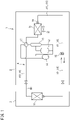
- FIG. 1 is a schematic configuration diagram of an air conditioner according to an embodiment of the present disclosure.
- An air conditioner 1 functioning as a refrigeration apparatus includes an outdoor unit 2 disposed outdoors and an indoor unit 3 disposed indoors.
- the outdoor unit 2 and the indoor unit 3 are connected to each other by a connection pipe.
- the air conditioner 1 includes a refrigerant circuit 4 configured to execute vapor compression refrigeration cycle operation.
- the refrigerant circuit 4 is provided with an indoor heat exchanger 11, a compressor 12, an oil separator 13, an outdoor heat exchanger 14, an expansion valve (expansion mechanism) 15, an accumulator 16, a four-way switching valve 17, and the like, which are connected by a refrigerant pipe 10.
- the refrigerant pipe 10 includes a liquid pipe 10L and a gas pipe 10G.
- the indoor heat exchanger 11 is configured to execute heat exchange between a refrigerant and indoor air, and is provided in the indoor unit 3.
- Examples of the indoor heat exchanger 11 include a fin-and-tube heat exchanger of a cross-fin type and a heat exchanger of a microchannel type.
- the indoor heat exchanger 11 is provided therearound with an indoor fan (not depicted) configured to send indoor air to the indoor heat exchanger 11.
- the compressor 12, the oil separator 13, the outdoor heat exchanger 14, the expansion valve 15, the accumulator 16, and the four-way switching valve 17 are provided in the outdoor unit 2.
- the compressor 12 is configured to compress a refrigerant sucked from a suction port and discharge the compressed refrigerant from a discharge port.
- Examples of the compressor 12 include various compressors such as a scroll compressor.
- the oil separator 13 is configured to separate lubricant from fluid mixture that contains the lubricant and a refrigerant and is discharged from the compressor 12. The refrigerant thus separated is sent to the four-way switching valve 17 whereas the lubricant is returned to the compressor 12.
- the outdoor heat exchanger 14 is configured to execute heat exchange between a refrigerant and outdoor air.
- the outdoor heat exchanger 14 according to the present embodiment is of the microchannel type.
- the outdoor heat exchanger 14 is provided therearound with an outdoor fan 18 configured to send outdoor air to the outdoor heat exchanger 14.
- the outdoor heat exchanger 14 has a liquid side end connected with a refrigerant flow divider 19 including a capillary tube.
- the expansion valve 15 is disposed between the outdoor heat exchanger 14 and the indoor heat exchanger 11 in the refrigerant circuit 4, and expands an incoming refrigerant to be decompressed to have predetermined pressure.
- Examples of the expansion valve 15 include an electronic expansion valve having a variable opening degree.
- the accumulator 16 is configured to separate an incoming refrigerant into a gas refrigerant and a liquid refrigerant, and is disposed between the suction port of the compressor 12 and the four-way switching valve 17 in the refrigerant circuit 4. The gas refrigerant thus separated at the accumulator 16 is sucked into the compressor 12.
- the four-way switching valve 17 is configured to be switchable between a first state indicated by solid lines in FIG. 1 and a second state indicated by broken lines.
- the four-way switching valve 17 is switched into the first state while the air conditioner 1 executes cooling operation, and the four-way switching valve 17 is switched into the second state while the air conditioner 1 executes heating operation.
- the outdoor heat exchanger 14 When the air conditioner 1 executes cooling operation, the outdoor heat exchanger 14 functions as a refrigerant condenser (radiator) and the indoor heat exchanger 11 functions as a refrigerant evaporator.
- the outdoor heat exchanger 14 functions as a refrigerant condenser and the indoor heat exchanger 11 functions as a refrigerant evaporator.
- the outdoor heat exchanger 14 functions as a refrigerant evaporator and the indoor heat exchanger 11 functions as a refrigerant condenser.
- a gas refrigerant discharged from the compressor 12 condenses at the indoor heat exchanger 11, is then decompressed at the expansion valve 15, and evaporates at the outdoor heat exchanger 14 to be sucked into the compressor 12.
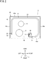
- FIG. 2 is a plan view depicting an interior of the air conditioner.
- FIG. 3 is a perspective view depicting the outdoor heat exchanger of the air conditioner.
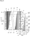
- FIG. 4 is a schematic developed view depicting the outdoor heat exchanger.
- the following description may include expressions such as “up”, “down”, “left”, “right”, “front (before)”, and “rear (behind)", for indication of directions and positions. These expressions follow directions indicated by arrows in FIG. 3 , unless otherwise specified. Specifically, the following description assumes that directions indicated by the arrow X in FIG. 3 are lateral directions, directions indicated by the arrow Y are front and rear method, and directions indicated by the arrow Z is vertical directions. These expressions describing the directions and the positions are adopted for convenience of description, and do not limit, unless otherwise specified, directions or positions of the entire outdoor heat exchanger 14 and various constituents of the outdoor heat exchanger 14 to the directions or the positions described herein.
- the outdoor unit 2 includes a case 40.
- the case 40 has a rectangular parallelepiped shape.
- the case 40 accommodates the compressor 12, the oil separator 13, the outdoor heat exchanger 14, the expansion valve 15, the accumulator 16, the four-way switching valve 17, the outdoor fan 18, and the like described earlier.
- FIG. 2 depicts, among these constituents, the compressor 12, the outdoor heat exchanger 14, and the accumulator 16, which are disposed on a bottom plate 41 of the case 40.
- the outdoor heat exchanger 14 faces four surfaces, namely, a left side surface, a rear surface, a right side surface, and a front surface of the case 40 in a top view. Part of the outdoor heat exchanger 14 facing the front surface of the case 40 is shorter than a width of the case 40 in a lateral direction X to face only an end part in the lateral direction X of the front surface of the case 40.
- the surfaces of the case 40 facing the outdoor heat exchanger 14 are each provided with an opening 40a for air supply.
- the outdoor heat exchanger 14 includes a pair of headers 21 and 22, and a heat exchanger body 23.
- the pair of headers 21 and 22 and the heat exchanger body 23 are made of aluminum or an aluminum alloy.
- the pair of headers 21 and 22 are disposed at respective ends of the heat exchanger body 23 in a top view.
- the header 21 is a liquid header configured to allow a liquid refrigerant (gas-liquid two-phase refrigerant) to flow therein.
- the header 22 is a gas header configured to allow a gas refrigerant to flow therein.
- the liquid header 21 and the gas header 22 are disposed to have longitudinal directions aligned to vertical directions Z.
- the liquid header 21 is connected with the refrigerant flow divider 19.
- the refrigerant flow divider 19 includes a flow divider body 19a provided therein with a branching flow path, a main refrigerant tube 19b extending from a first end of the flow divider body 19a and connected to the expansion valve 15 (see FIG. 1 ), and a plurality of capillary tubes 37 extending from a second end of the flow divider body 19a.
- the capillary tubes 37 are each connected to the liquid header 21 via a connecting tube 35.
- the gas header 22 is connected with a gas pipe 24.
- the heat exchanger body 23 is configured to execute heat exchange between a refrigerant flowing inside and air. As depicted in FIG. 4 , the heat exchanger body 23 includes a plurality of heat transfer tubes 26 and a plurality of fins 27. The heat transfer tubes 26 are disposed horizontally. The plurality of heat transfer tubes 26 is aligned in the vertical directions Z. Each of the heat transfer tubes 26 has a first longitudinal end portion connected to the liquid header 21. Each of the heat transfer tubes 26 has a second longitudinal end portion connected to the gas header 22.
- Examples of the heat transfer tubes 26 include a flat porous tube having a plurality of holes serving as refrigerant flow paths and aligned horizontally.
- the plurality of fins 27 is aligned longitudinally along the heat transfer tubes 26.
- the refrigerant unidirectionally flows from the liquid header 21 to the gas header 22 through the heat exchanger body 23, or unidirectionally flows from the gas header 22 to the liquid header 21 through the heat exchanger body 23.
- the heat exchanger body 23 exemplarily depicted in FIG. 3 and FIG. 4 includes a plurality of heat exchange units 31A to 31F.
- the plurality of heat exchange units 31A to 31F is aligned in the vertical direction Z.
- the liquid header 21 has an interior vertically zoned respectively for the heat exchange units 31A to 31F.
- the interior of the liquid header 21 is provided with flow paths 33A to 33F respectively for the heat exchange units 31A to 31F.
- the liquid header 21 is connected with a plurality of connecting tubes 35A to 35F.
- the connecting tubes 35Ato 35F are provided correspondingly to the flow paths 33Ato 33F.
- the connecting tubes 35A to 35F are connected with capillary tubes 37A to 37F of the refrigerant flow divider 19.
- a liquid refrigerant obtained through dividing by the refrigerant flow divider 19 flows through the capillary tubes 37A to 37F and the connecting tubes 35Ato 35F, flows into the flow paths 33Ato 33F in the liquid header 21, and flows through one or some of the heat transfer tubes 26 connected to the flow paths 33A to 33F to reach the gas header 22.
- the refrigerant divided into the heat transfer tubes 26 at the gas header 22 flows into the flow paths 33A to 33F of the liquid header 21, and flows from the flow paths 33A to 33F to the capillary tubes 37A to 37F to join at the refrigerant flow divider 19.
- the gas header 22 has an interior not zoned but provided continuously for all the heat exchange units 31A to 31F.
- the refrigerant flowing from the single gas pipe 24 into the gas header 22 is accordingly divided into all the heat transfer tubes 26, and the refrigerant flowing from all the heat transfer tubes 26 into the gas header 22 is joined at the gas header 22 to flow into the single gas pipe 24.
- FIG. 5 is a front view of the liquid header.
- FIG. 6 is a left side view of the liquid header.
- FIG. 7 is a sectional view taken along arrow B-B indicated in FIG. 5 .
- the first connecting tube 35A connected to the liquid header 21 at a lowest height and the second connecting tube 35B connected to the liquid header 21 at a second lowest height are disposed to have a first space t1 (see FIG. 5 ) therebetween in the vertical direction Z.
- the second connecting tube 35B and the third connecting tube 35C connected to the liquid header 21 at a third lowest height are disposed to have a second space t2 therebetween in the vertical direction Z.
- the first space t1 is smaller than the second space t2, and the first connecting tube 35A and the second connecting tube 35B are connected to the liquid header 21 at close positions in the vertical direction Z.
- the first connecting tube 35A and the second connecting tube 35B are connected to the liquid header 21 at positions adjacent to the bottom plate 41 of the case 40.
- the third connecting tube 35C is connected to the liquid header 21 at a position higher than the predetermined height H from the bottom plate 41 of the case 40.
- the predetermined height H is set as a height that can be reached by ice grown due to an ice-up phenomenon to be described later.
- the first connecting tube 35A includes a horizontal portion 35A1 extending linearly in a horizontal direction and in the lateral direction X from the liquid header 21, a slant portion 35A2 extending backward and diagonally upward from a distal end of the horizontal portion 35A1, and a vertical portion 35A3 extending vertically upward from an upper end of the slant portion 35A2.
- the vertical portion 35A3 has an upper end provided with a diameter expanding portion 35A4 having an expanding diameter.
- the second connecting tube 35B extends linearly in the horizontal direction and in the lateral direction X from the liquid header 21.
- the second connecting tube 35B extends horizontally from the liquid header 21 beyond the horizontal portion 35A1 of the first connecting tube 35A.
- the second connecting tube 35B has a distal end part provided with a diameter expanding portion 35B1 having an expanding diameter.
- the third connecting tube 35C extends linearly in the horizontal direction and in the lateral direction X from the liquid header 21.
- the third connecting tube 35C is equal in length in the lateral direction X to the second connecting tube 35B.
- the third connecting tube 35C is in parallel with the second connecting tube 35B.
- the third connecting tube 35C is disposed right above the second connecting tube 35B.
- the second connecting tube 35B and the third connecting tube 35C are aligned in the vertical direction Z.
- the third connecting tube 35C has a distal end part provided with a diameter expanding portion 35C1 having an expanding diameter.
- the first to third connecting tubes 35A to 35C are connected respectively with the capillary tubes 37A to 37C of the refrigerant flow divider 19. As depicted in FIG. 6 , the first connecting tube 35A is connected with the first capillary tube 37A. Specifically, the first capillary tube 37A is inserted and joined to the diameter expanding portion 35A4 of the first connecting tube 35A.
- the second capillary tube 37B connected to the second connecting tube 35B includes a horizontal portion 37B1, a curved portion 37B2, and a vertical portion 37B3.
- the horizontal portion 37B1 extends in the horizontal direction and in the lateral direction X.
- the horizontal portion 37B1 has a first end connected to a distal end of the second connecting tube 35B. Specifically, the first end of the horizontal portion 37B1 is inserted and joined to the diameter expanding portion 35B1 of the second connecting tube 35B.
- the horizontal portion 37B1 has a second end provided continuously to the curved portion 37B2.
- the curved portion 37B2 is curved upward from the second end of the horizontal portion 37B1.
- the curved portion 37B2 is curved at an angle having about 90 degrees.
- the vertical portion 37B3 extends upward from the curved portion 37B2.
- the third capillary tube 37C connected to the third connecting tube 35C includes a horizontal portion 37C1, a curved portion 37C2, and a vertical portion 37C3.
- the horizontal portion 37C1 extends horizontally in the lateral direction X.
- the horizontal portion 37C1 has a first end connected to a distal end of the third connecting tube 35C. Specifically, the first end of the horizontal portion 37C1 is inserted and joined to the diameter expanding portion 35C1 of the third connecting tube 35C.
- the horizontal portion 37C1 has a second end provided continuously to the curved portion 37C2.
- the curved portion 37C2 is curved upward from the second end of the horizontal portion 37C1.
- the curved portion 37C2 is curved at an angle having about 90 degrees.
- the vertical portion 37C3 extends upward from the curved portion 37C2.
- the second connecting tube 35B and the third connecting tube 35C are collectively called a "first refrigerant tube 51"
- the third connecting tube 35C and the third capillary tube 37C are collectively called a "second refrigerant tube 52”.
- the first refrigerant tube 51 includes a first portion 51A having a first end connected to the liquid header 21 and extending horizontally.
- the first portion 51A includes the second connecting tube 35B and the horizontal portion 37B1 of the second capillary tube 37B.
- the second refrigerant tube 52 includes a second portion 52A having a first end connected to the liquid header 21 and extending horizontally.
- the second portion 52A includes the third connecting tube 35C and the horizontal portion 37C1 of the third capillary tube 37C.
- the first portion 51A and the second portion 52A are positioned to be overlapped with each other in the vertical direction Z.
- the first portion 51A and the second portion 52A are in parallel with each other, and are aligned in the vertical direction Z.
- the second portion 52A is shorter in the lateral direction X than the first portion 51A.
- the first portion 51A of the first refrigerant tube 51 is surrounded with a heat insulating material 60.
- the heat insulating material 60 is wound around to entirely cover the first portion 51A.
- Examples of the heat insulating material 60 include publicly known members such as polyethylene foam, rigid urethane foam, and phenolic foam.
- the heat insulating material 60 according to the present embodiment is attached to the first portion 51A as well as to the horizontal portion 35A1 of the first connecting tube 35A disposed therebelow.
- the heat insulating material 60 is provided entirely in a longitudinal direction of the first portion 51A. Specifically, the heat insulating material 60 has an end part positioned adjacent to the liquid header 21 so as to be in contact with the liquid header 21. The heat insulating material 60 has another end part positioned far from the liquid header 21 to be overlapped with the curved portion 37B2 of the first refrigerant tube 51. The heat insulating material 60 is provided in a region wider than the second portion 52A of the second refrigerant tube 52 in the lateral direction X.
- the heat insulating material 60 is provided around the first portion 51A of the first refrigerant tube 51 as described above for the following reason.
- the first and second refrigerant tubes 51 and 52 each have a flow of a refrigerant lower in temperature than outdoor air, so that condensate or frost may adhere to the first and second refrigerant tubes 51 and 52.
- the heat insulating material 60 is attached to the first portion 51A of the first refrigerant tube 51, to inhibit condensate or frost from adhering to the first portion 51A.
- the water may adhere to the first portion 51A of the first refrigerant tube 51 disposed below the second portion 52A.
- the heat insulating material 60 is attached to the first portion 51A, so that the dropping water is less likely to adhere directly to the first portion 51A. This inhibits freezing of water adhering to the first portion 51A upon transition from defrosting operation to heating operation.
- the heat insulating material 60 is attached to the first portion 51A, to inhibit the first portion 51A from being directly covered with ice even when the ice-up phenomenon occurs.
- the second portion 52A of the second refrigerant tube 52 has the diameter expanding portion 35C1 having an expanding outer diameter. Water adhering to the second portion 52A sometimes flows along the second portion 52A, but such a flow may be blocked by a shape changed portion such as the diameter expanding portion 35C1 and water may drop downward.
- the second portion 52A has an end part positioned far from the liquid header 21 and continuously provided with the curved portion 37C2. A water flow may be blocked by a shape changed portion such as the curved portion 37C2 and water may drop downward.
- the heat insulating material 60 is provided around the first portion 51A right below the shape changed portion in the second refrigerant tube 52, so that dropping water does not adhere directly to the first portion 51A.
- the bottom plate 41 of the case 40 is curved such that a convex portion 41a and a concave portion 41b are disposed alternately in the lateral direction X.
- the first portion 51A of the first refrigerant tube 51 is disposed above and adjacent to the convex portion 41a of the bottom plate 41, and is thus more likely to be covered with ice when the ice-up phenomenon occurs.
- the heat insulating material 60 according to the present embodiment is provided around the first portion 51A at a position above the convex portion 41a of the bottom plate 41, to inhibit the first portion 51A from being directly covered with ice in a case where the bottom plate 41, which is likely to have the ice-up phenomenon, and the first portion 51A have a short vertical distance.
- the heat insulating material 60 has a first end positioned at the curved portion 37B2 of the first refrigerant tube 51. Even when water adhering to the vertical portion 37B3 flows downward and reaches the curved portion 37B2, this configuration inhibits the water from adhering to the first portion 51A.
- the liquid header 21 of the outdoor heat exchanger 14 is supported by a bottom frame 43 of the case 40 via a support plate 44.
- the bottom frame 43 includes the bottom plate 41 described above, and legs 42 supporting the bottom plate 41 from below.
- the bottom frame 43 is made of a metal.
- the legs 42 are provided under a front end edge and under a rear end edge of the bottom plate 41 and extend in the lateral direction X.
- the front leg 42 has an upper surface provided with a projection piece 42a projecting upward, and the support plate 44 is attached to the projection piece 42a.
- the support plate 44 is made of a metal board.
- the support plate 44 includes a body portion 44a disposed along a front surface of the liquid header 21, and an attachment portion 44b projecting forward from a lower surface of the body portion 44a.
- the attachment portion 44b includes an attachment piece 44b1 overlapped with the projection piece 42a.
- the projection piece 42a and the attachment piece 44b1 are coupled to each other by a bolt 45.
- the body portion 44a is made of a board having a rectangular shape in a front view.
- the body portion 44a is provided with an opening 44a1 and a support piece 44a2.
- the opening 44a1 is an oblong hole penetrating the body portion 44a in front and rear direction.
- the support piece 44a2 projects backward from a side of the opening 44a1. As depicted in FIG. 7 , the support piece 44a2 is formed by bending backward part of the body portion 44a to provide the opening 44a1.
- the front surface of the liquid header 21 is disposed along part of the body portion 44a, and a left side surface of the liquid header 21is disposed along the support piece 44a2, and the body portion 44a and the liquid header 21 are bound together by a binder 46 passing through the opening 44a1, so as to couple the liquid header 21 to the support plate 44.
- the support plate 44 and the liquid header 21 interpose an insulator 47 made of rubber or the like, to inhibit electrolytic corrosion due to contact between the support plate 44 and the liquid header 21.
- the insulator 47 and the liquid header 21 interpose a heat insulating material 48.
- the heat insulating material 48 inhibits heat transfer from the liquid header 21 to the support plate 44, to inhibit adhesion of condensate and frost to the support plate 44.
- FIG. 8 is a sectional view taken along line A-A indicated in FIG. 5 .
- the legs 42 of the case 40 each have a seat 42b supporting the concave portion 41b of the bottom plate 41 from below.
- the seat 42b is disposed below an opening 41c provided in the convex portion 41a of the bottom plate 41, below the first and second refrigerant tubes 51 and 52.
- the seat 42b is made of a metal. When the seat 42b is cooled by outdoor air, the accumulated water may freeze to cause the ice-up phenomenon.
- the present embodiment provides a slant member 61 to inhibit freezing of water on the seat 42b.
- the slant member 61 has a triangular prism shape, and has a side surface 61a attached onto the seat 42b.
- the slant member 61 has an upper surface 61b that is slant to have a higher front portion and a lower rear portion.
- the upper surface 61b of the slant member 61 is sized to include an entire downward projected area of the opening 41c.
- the upper surface 61b of the slant member 61 has a lower end disposed adjacent to a rear edge 42b1 of the seat 42b. Accordingly, water passing through the opening 41c drops onto the upper surface 61b of the slant member 61 and flows along a slant of the upper surface 61b, to be inhibited from accumulating on the seat 42b.
- the slant member 61 is made of a material lower in heat conductivity than the seat 42b made of a metal, such as rubber or a synthetic resin. Water dropping onto the upper surface 61b of the slant member 61 is thus inhibited from freezing on the upper surface 61b.
- each of the first refrigerant tube 51 and the second refrigerant tube 52 may be constituted by a different one of the connecting tubes 35 and a different one of the capillary tubes 37.
- Each of the first portion 51A of the first refrigerant tube 51 and the second portion 52A of the second refrigerant tube 52 has an end connected to the liquid header 21.
- the first portion 51A and the second portion 52A may not be necessarily connected to the liquid header 21, but have only to be positioned between the liquid header 21 and the flow divider body 19a of the refrigerant flow divider 19 (see FIG. 4 ).
- the first portion A of the first refrigerant tube 51 and the second portion 52A of the second refrigerant tube 52 may be slant with respect to the horizontal direction.
- the first portion A of the first refrigerant tube 51 and the second portion 52A of the second refrigerant tube 52 may not be in parallel with each other. For example, one may extend in the horizontal direction and the other may be slant with respect to the horizontal direction.
- the first portion A of the first refrigerant tube 51 and the second portion 52A of the second refrigerant tube 52 have only to be partially overlapped with each other in the vertical direction in a planar view.
- the heat insulating material 60 has only to be positioned above and correspondingly to at least the convex portion 41a of the bottom plate 41 in the first portion 51A, and may not be necessarily positioned above and correspondingly to the concave portion 41b that is hardly reached by ice grown due to the ice-up phenomenon.
- the ice-up phenomenon is less likely to occur also in a case where the convex portion 41a of the bottom plate 41 is provided with the opening 41c penetrating in the vertical direction Z. Accordingly, the heat insulating material 60 may not be provided on a portion positioned above the opening 41c.
- the first portion 51A overlapped with the second portion 52A in the vertical direction Z may be provided with the heat insulating material 60 in order to prevent water dropping from the second portion 52A of the second refrigerant tube 52 from adhering to the first portion 51A of the first refrigerant tube 51.
- the first portion 51A disposed above the bottom plate 41 may be provided with the heat insulating material 60.
- the heat insulating material 60 inhibits freezing on the first portion 51A also in this case.
- the outdoor heat exchanger 14 faces the four side surfaces of the case 40.
- the outdoor heat exchanger 14 may have a substantially U shape in a top view to face three side surfaces of the case 40, or may have a substantially L shape in a top view to face two side surfaces.
- the refrigerant flow divider 19 may alternatively be disposed laterally to the liquid header 21 in the lateral directions X.
- the above embodiment describes the air conditioner 1 assuming that the arrow Z indicates the vertical directions, the arrow Y indicates the front and rear directions, and the arrow X indicates the lateral directions.
- the present disclosure should not be limited to this case, and the arrow X may indicate the front and rear directions and the arrow Y may indicate the lateral directions.
Landscapes
- Engineering & Computer Science (AREA)
- General Engineering & Computer Science (AREA)
- Mechanical Engineering (AREA)
- Chemical & Material Sciences (AREA)
- Combustion & Propulsion (AREA)
- Physics & Mathematics (AREA)
- Thermal Sciences (AREA)
- Geometry (AREA)
- Other Air-Conditioning Systems (AREA)
Abstract
Description
- The present disclosure relates to an air conditioner.
- PATENT LITERATURE 1 discloses an air conditioner including a heat exchanger and a refrigerant flow divider configured to divide a liquid refrigerant into a plurality of paths and flow the refrigerant into the heat exchanger. The refrigerant flow divider includes a flow divider body having an internal branching flow path, and a plurality of refrigerant tubes connected to a lower surface of the flow divider body. The refrigerant tubes are each connected to a liquid header of the heat exchanger. The plurality of refrigerant tubes is connected to the liquid header at portions aligned to be vertically spaced apart from each other.
- PATENT LITERATURE 1:
Japanese Patent No. 6522178 - The heat exchanger and the refrigerant tubes may have frost formed thereon during heating operation under a condition with low outdoor temperature. The air conditioner thus executes the defrosting operation while periodically flowing a refrigerant having high temperature to the heat exchanger in order to melt the frost. The plurality of refrigerant tubes is connected to the liquid header at the portions aligned to be vertically spaced apart from each other. Water obtained by melting the frost during defrosting operation may drop onto a lower refrigerant tube and freeze during repeated heating operation.
- It is an object of the present disclosure to provide an air conditioner inhibiting water dropping from an upper one of a plurality of refrigerant tubes aligned vertically from freezing on a lower one of the refrigerant tubes.
-
- (1) The present disclosure provides an air conditioner including:
- a first refrigerant tube including a first portion, and allowing a flow of a liquid refrigerant; and
- a second refrigerant tube including a second portion positioned above the first portion to be vertically overlapped with the first portion, and allowing a flow of a liquid refrigerant; in which
- the first portion is surrounded with a heat insulating material.
In the air conditioner thus configured, even when frost or the like adhering to the second portion of the second refrigerant tube melts and water adhering to the second portion drops onto the first portion, the dropping water is inhibited from freezing on the first portion since the first portion is provided with the heat insulating material. - (2) Preferably, the first portion and the second portion are in parallel with each other and are aligned vertically.
When the first portion and the second portion are in parallel with each other and are aligned vertically as in the above configuration, water dropping from the second portion is likely to adhere to the first portion and it is accordingly more effective to provide the heat insulating material on the first portion. - (3) Preferably, the air conditioner further includes a heat exchanger including a liquid header, and
the first refrigerant tube and the second refrigerant tube are connected to the liquid header. - (4) Preferably, the first portion and the second portion extend horizontally.
- (5) Preferably, each of the first portion and the second portion has a first end part connected to the liquid header.
- (6) Preferably, the first refrigerant tube includes a curved portion bent upward from an opposite end part of the first end part of the first portion, and a third portion extending upward from the curved portion, and
the heat insulating material has an end part positioned adjacent to the third portion and at the curved portion.
Even when water adhering to the third portion flows downward along the third portion and reaches the first portion via the curved portion, this configuration inhibits the water from freezing on the first portion. - (7) Preferably, the heat insulating material is provided right below a position having change in shape of the second refrigerant tube at least in the first portion.
When the second refrigerant tube is changed in shape due to increase in diameter (flare), curving, or the like, a flow of water adhering to the second refrigerant tube is blocked at the position having change in shape and the water is likely to drop downward. The heat insulating material provided on the first portion right below the position inhibits freezing of the dropping water on the first portion. - (8) Preferably, the air conditioner further includes a case including a bottom plate and accommodating the first refrigerant tube, the second refrigerant tube, and the heat exchanger, and
the first portion is disposed adjacent to the bottom plate.
When water obtained by melting frost at an upper or lower refrigerant tube drops and accumulates on the bottom plate (drain pan) of the air conditioner executing defrosting operation, the water may freeze during repeated heating operation and cause an ice-up phenomenon of gradually growing ice upward. The heat insulating material is provided on the first portion disposed adjacent to the bottom plate, to inhibit the first portion from being directly covered with ice even when the ice-up phenomenon occurs. - (9) Preferably, the first portion is disposed vertically within a range of 50 mm from the bottom plate, and the second portion is disposed vertically within a range exceeding 50 mm from the bottom plate.
- (10) Preferably, the heat insulating material is provided right above a position not provided with an opening or a concave portion of the bottom plate at least in the first portion.
When the bottom plate of the case is provided with the opening or the concave portion, water dropping thereabove is exhausted from the opening or accumulates in the concave portion, and the first portion is less likely to be covered with ice even when the ice-up phenomenon occurs. If the bottom plate is not provided with the opening or the concave portion, the first portion is more likely to be covered with ice due to the ice-up phenomenon. Accordingly, when the heat insulating material is provided on the first portion right above the position not provided with the opening or the concave portion of the bottom plate, the first portion is inhibited from being directly covered with ice. - (11) Preferably, the case is provided with a support plate supporting the liquid header, and the liquid header and the support plate interpose a second heat insulating material.
This configuration provides the second heat insulating material between the liquid header and the support plate, to inhibit frosting and freezing on the support plate that is cooled by the liquid header. - (12) Preferably, below the first portion, the bottom plate is provided with an opening for drainage,
- the case includes a metal component disposed below and spaced apart from the opening, and
- the metal component below the opening is provided thereon with a slant member having an upper surface slant with respect to a horizontal direction and being lower in heat conductivity than the metal component.
- In this configuration, water dropping through the opening of the bottom plate can be received by the slant member and flow due to the slant of the slant member, to inhibit freezing of water on the metal component.
-
- [
FIG. 1] FIG. 1 is a schematic configuration diagram of an air conditioner according to an embodiment of the present disclosure. - [
FIG. 2] FIG. 2 is a plan view depicting an interior of the air conditioner. - [
FIG. 3] FIG. 3 is a perspective view depicting an outdoor heat exchanger of the air conditioner. - [
FIG. 4] FIG. 4 is a schematic developed view depicting an outdoor heat exchanger. - [
FIG. 5] FIG. 5 is a front view of a liquid header. - [
FIG. 6] FIG. 6 is a left side view of the liquid header. - [
FIG. 7] FIG. 7 is a sectional view taken along arrow B-B indicated inFIG. 5 . - [
FIG. 8] FIG. 8 is a sectional view taken along arrow A-A indicated inFIG. 5 . -
FIG. 1 is a schematic configuration diagram of an air conditioner according to an embodiment of the present disclosure. - An air conditioner 1 functioning as a refrigeration apparatus includes an
outdoor unit 2 disposed outdoors and an indoor unit 3 disposed indoors. Theoutdoor unit 2 and the indoor unit 3 are connected to each other by a connection pipe. The air conditioner 1 includes arefrigerant circuit 4 configured to execute vapor compression refrigeration cycle operation. Therefrigerant circuit 4 is provided with anindoor heat exchanger 11, acompressor 12, anoil separator 13, anoutdoor heat exchanger 14, an expansion valve (expansion mechanism) 15, anaccumulator 16, a four-way switching valve 17, and the like, which are connected by arefrigerant pipe 10. Therefrigerant pipe 10 includes aliquid pipe 10L and agas pipe 10G. - The
indoor heat exchanger 11 is configured to execute heat exchange between a refrigerant and indoor air, and is provided in the indoor unit 3. Examples of theindoor heat exchanger 11 include a fin-and-tube heat exchanger of a cross-fin type and a heat exchanger of a microchannel type. Theindoor heat exchanger 11 is provided therearound with an indoor fan (not depicted) configured to send indoor air to theindoor heat exchanger 11. - The
compressor 12, theoil separator 13, theoutdoor heat exchanger 14, theexpansion valve 15, theaccumulator 16, and the four-way switching valve 17 are provided in theoutdoor unit 2. - The
compressor 12 is configured to compress a refrigerant sucked from a suction port and discharge the compressed refrigerant from a discharge port. Examples of thecompressor 12 include various compressors such as a scroll compressor. - The
oil separator 13 is configured to separate lubricant from fluid mixture that contains the lubricant and a refrigerant and is discharged from thecompressor 12. The refrigerant thus separated is sent to the four-way switching valve 17 whereas the lubricant is returned to thecompressor 12. - The
outdoor heat exchanger 14 is configured to execute heat exchange between a refrigerant and outdoor air. Theoutdoor heat exchanger 14 according to the present embodiment is of the microchannel type. Theoutdoor heat exchanger 14 is provided therearound with anoutdoor fan 18 configured to send outdoor air to theoutdoor heat exchanger 14. Theoutdoor heat exchanger 14 has a liquid side end connected with arefrigerant flow divider 19 including a capillary tube. - The
expansion valve 15 is disposed between theoutdoor heat exchanger 14 and theindoor heat exchanger 11 in therefrigerant circuit 4, and expands an incoming refrigerant to be decompressed to have predetermined pressure. Examples of theexpansion valve 15 include an electronic expansion valve having a variable opening degree. - The
accumulator 16 is configured to separate an incoming refrigerant into a gas refrigerant and a liquid refrigerant, and is disposed between the suction port of thecompressor 12 and the four-way switching valve 17 in therefrigerant circuit 4. The gas refrigerant thus separated at theaccumulator 16 is sucked into thecompressor 12. - The four-
way switching valve 17 is configured to be switchable between a first state indicated by solid lines inFIG. 1 and a second state indicated by broken lines. The four-way switching valve 17 is switched into the first state while the air conditioner 1 executes cooling operation, and the four-way switching valve 17 is switched into the second state while the air conditioner 1 executes heating operation. - When the air conditioner 1 executes cooling operation, the
outdoor heat exchanger 14 functions as a refrigerant condenser (radiator) and theindoor heat exchanger 11 functions as a refrigerant evaporator. A gas refrigerant discharged from thecompressor 12 condenses at theoutdoor heat exchanger 14, is then decompressed at theexpansion valve 15, and evaporates at theindoor heat exchanger 11 to be sucked into thecompressor 12. Also during defrosting operation of removing frost adhering to theoutdoor heat exchanger 14 due to heating operation, as in cooling operation, theoutdoor heat exchanger 14 functions as a refrigerant condenser and theindoor heat exchanger 11 functions as a refrigerant evaporator. - When the air conditioner 1 executes heating operation, the
outdoor heat exchanger 14 functions as a refrigerant evaporator and theindoor heat exchanger 11 functions as a refrigerant condenser. A gas refrigerant discharged from thecompressor 12 condenses at theindoor heat exchanger 11, is then decompressed at theexpansion valve 15, and evaporates at theoutdoor heat exchanger 14 to be sucked into thecompressor 12. -
FIG. 2 is a plan view depicting an interior of the air conditioner.FIG. 3 is a perspective view depicting the outdoor heat exchanger of the air conditioner.FIG. 4 is a schematic developed view depicting the outdoor heat exchanger. - The following description may include expressions such as "up", "down", "left", "right", "front (before)", and "rear (behind)", for indication of directions and positions. These expressions follow directions indicated by arrows in
FIG. 3 , unless otherwise specified. Specifically, the following description assumes that directions indicated by the arrow X inFIG. 3 are lateral directions, directions indicated by the arrow Y are front and rear method, and directions indicated by the arrow Z is vertical directions. These expressions describing the directions and the positions are adopted for convenience of description, and do not limit, unless otherwise specified, directions or positions of the entireoutdoor heat exchanger 14 and various constituents of theoutdoor heat exchanger 14 to the directions or the positions described herein. - The
outdoor unit 2 includes acase 40. Thecase 40 has a rectangular parallelepiped shape. Thecase 40 accommodates thecompressor 12, theoil separator 13, theoutdoor heat exchanger 14, theexpansion valve 15, theaccumulator 16, the four-way switching valve 17, theoutdoor fan 18, and the like described earlier.FIG. 2 depicts, among these constituents, thecompressor 12, theoutdoor heat exchanger 14, and theaccumulator 16, which are disposed on abottom plate 41 of thecase 40. - The
outdoor heat exchanger 14 according to the present embodiment faces four surfaces, namely, a left side surface, a rear surface, a right side surface, and a front surface of thecase 40 in a top view. Part of theoutdoor heat exchanger 14 facing the front surface of thecase 40 is shorter than a width of thecase 40 in a lateral direction X to face only an end part in the lateral direction X of the front surface of thecase 40. The surfaces of thecase 40 facing theoutdoor heat exchanger 14 are each provided with anopening 40a for air supply. Theoutdoor heat exchanger 14 includes a pair ofheaders heat exchanger body 23. The pair ofheaders heat exchanger body 23 are made of aluminum or an aluminum alloy. - The pair of
headers heat exchanger body 23 in a top view. Theheader 21 is a liquid header configured to allow a liquid refrigerant (gas-liquid two-phase refrigerant) to flow therein. Theheader 22 is a gas header configured to allow a gas refrigerant to flow therein. Theliquid header 21 and thegas header 22 are disposed to have longitudinal directions aligned to vertical directions Z. - As depicted in
FIG. 4 , theliquid header 21 is connected with therefrigerant flow divider 19. Therefrigerant flow divider 19 includes aflow divider body 19a provided therein with a branching flow path, a mainrefrigerant tube 19b extending from a first end of theflow divider body 19a and connected to the expansion valve 15 (seeFIG. 1 ), and a plurality ofcapillary tubes 37 extending from a second end of theflow divider body 19a. Thecapillary tubes 37 are each connected to theliquid header 21 via a connectingtube 35. Thegas header 22 is connected with agas pipe 24. - The
heat exchanger body 23 is configured to execute heat exchange between a refrigerant flowing inside and air. As depicted inFIG. 4 , theheat exchanger body 23 includes a plurality ofheat transfer tubes 26 and a plurality offins 27. Theheat transfer tubes 26 are disposed horizontally. The plurality ofheat transfer tubes 26 is aligned in the vertical directions Z. Each of theheat transfer tubes 26 has a first longitudinal end portion connected to theliquid header 21. Each of theheat transfer tubes 26 has a second longitudinal end portion connected to thegas header 22. - Examples of the
heat transfer tubes 26 include a flat porous tube having a plurality of holes serving as refrigerant flow paths and aligned horizontally. The plurality offins 27 is aligned longitudinally along theheat transfer tubes 26. The refrigerant unidirectionally flows from theliquid header 21 to thegas header 22 through theheat exchanger body 23, or unidirectionally flows from thegas header 22 to theliquid header 21 through theheat exchanger body 23. - The
heat exchanger body 23 exemplarily depicted inFIG. 3 andFIG. 4 includes a plurality ofheat exchange units 31A to 31F. The plurality ofheat exchange units 31A to 31F is aligned in the vertical direction Z. Theliquid header 21 has an interior vertically zoned respectively for theheat exchange units 31A to 31F. In other words, as depicted inFIG. 3 , the interior of theliquid header 21 is provided withflow paths 33A to 33F respectively for theheat exchange units 31A to 31F. - The
liquid header 21 is connected with a plurality of connectingtubes 35A to 35F. The connectingtubes 35Ato 35F are provided correspondingly to theflow paths 33Ato 33F. The connectingtubes 35A to 35F are connected withcapillary tubes 37A to 37F of therefrigerant flow divider 19. - During heating operation, a liquid refrigerant obtained through dividing by the
refrigerant flow divider 19 flows through thecapillary tubes 37A to 37F and the connectingtubes 35Ato 35F, flows into theflow paths 33Ato 33F in theliquid header 21, and flows through one or some of theheat transfer tubes 26 connected to theflow paths 33A to 33F to reach thegas header 22. In contrast, during cooling operation or defrosting operation, the refrigerant divided into theheat transfer tubes 26 at thegas header 22 flows into theflow paths 33A to 33F of theliquid header 21, and flows from theflow paths 33A to 33F to thecapillary tubes 37A to 37F to join at therefrigerant flow divider 19. - The
gas header 22 has an interior not zoned but provided continuously for all theheat exchange units 31A to 31F. The refrigerant flowing from thesingle gas pipe 24 into thegas header 22 is accordingly divided into all theheat transfer tubes 26, and the refrigerant flowing from all theheat transfer tubes 26 into thegas header 22 is joined at thegas header 22 to flow into thesingle gas pipe 24. -
FIG. 5 is a front view of the liquid header.FIG. 6 is a left side view of the liquid header.FIG. 7 is a sectional view taken along arrow B-B indicated inFIG. 5 . - As depicted in
FIG. 5 andFIG. 6 , among the plurality of connectingtubes 35 A to 35F, the first connectingtube 35A connected to theliquid header 21 at a lowest height and the second connectingtube 35B connected to theliquid header 21 at a second lowest height are disposed to have a first space t1 (seeFIG. 5 ) therebetween in the vertical direction Z. The second connectingtube 35B and the third connectingtube 35C connected to theliquid header 21 at a third lowest height are disposed to have a second space t2 therebetween in the vertical direction Z. - The first space t1 is smaller than the second space t2, and the first connecting
tube 35A and the second connectingtube 35B are connected to theliquid header 21 at close positions in the vertical direction Z. The first connectingtube 35A and the second connectingtube 35B are connected to theliquid header 21 at positions adjacent to thebottom plate 41 of thecase 40. Specifically, the first connectingtube 35A and the second connectingtube 35B are connected to theliquid header 21 at positions lower than a predetermined height H, e.g. H = 50 mm, from thebottom plate 41 of thecase 40. The third connectingtube 35C is connected to theliquid header 21 at a position higher than the predetermined height H from thebottom plate 41 of thecase 40. The predetermined height H is set as a height that can be reached by ice grown due to an ice-up phenomenon to be described later. - The first connecting
tube 35A includes a horizontal portion 35A1 extending linearly in a horizontal direction and in the lateral direction X from theliquid header 21, a slant portion 35A2 extending backward and diagonally upward from a distal end of the horizontal portion 35A1, and a vertical portion 35A3 extending vertically upward from an upper end of the slant portion 35A2. The vertical portion 35A3 has an upper end provided with a diameter expanding portion 35A4 having an expanding diameter. - As depicted in
FIG. 5 , the second connectingtube 35B extends linearly in the horizontal direction and in the lateral direction X from theliquid header 21. The second connectingtube 35B extends horizontally from theliquid header 21 beyond the horizontal portion 35A1 of the first connectingtube 35A. The second connectingtube 35B has a distal end part provided with a diameter expanding portion 35B1 having an expanding diameter. - As depicted in
FIG. 5 , the third connectingtube 35C extends linearly in the horizontal direction and in the lateral direction X from theliquid header 21. The third connectingtube 35C is equal in length in the lateral direction X to the second connectingtube 35B. The third connectingtube 35C is in parallel with the second connectingtube 35B. The third connectingtube 35C is disposed right above the second connectingtube 35B. The second connectingtube 35B and the third connectingtube 35C are aligned in the vertical direction Z. The third connectingtube 35C has a distal end part provided with a diameter expanding portion 35C1 having an expanding diameter. - The first to third connecting
tubes 35A to 35C are connected respectively with thecapillary tubes 37A to 37C of therefrigerant flow divider 19. As depicted inFIG. 6 , the first connectingtube 35A is connected with the firstcapillary tube 37A. Specifically, the firstcapillary tube 37A is inserted and joined to the diameter expanding portion 35A4 of the first connectingtube 35A. - As depicted in
FIG. 5 , the secondcapillary tube 37B connected to the second connectingtube 35B includes a horizontal portion 37B1, a curved portion 37B2, and a vertical portion 37B3. The horizontal portion 37B1 extends in the horizontal direction and in the lateral direction X. The horizontal portion 37B1 has a first end connected to a distal end of the second connectingtube 35B. Specifically, the first end of the horizontal portion 37B1 is inserted and joined to the diameter expanding portion 35B1 of the second connectingtube 35B. The horizontal portion 37B1 has a second end provided continuously to the curved portion 37B2. The curved portion 37B2 is curved upward from the second end of the horizontal portion 37B1. The curved portion 37B2 is curved at an angle having about 90 degrees. The vertical portion 37B3 extends upward from the curved portion 37B2. - The third
capillary tube 37C connected to the third connectingtube 35C includes a horizontal portion 37C1, a curved portion 37C2, and a vertical portion 37C3. The horizontal portion 37C1 extends horizontally in the lateral direction X. The horizontal portion 37C1 has a first end connected to a distal end of the third connectingtube 35C. Specifically, the first end of the horizontal portion 37C1 is inserted and joined to the diameter expanding portion 35C1 of the third connectingtube 35C. The horizontal portion 37C1 has a second end provided continuously to the curved portion 37C2. The curved portion 37C2 is curved upward from the second end of the horizontal portion 37C1. The curved portion 37C2 is curved at an angle having about 90 degrees. The vertical portion 37C3 extends upward from the curved portion 37C2. - Detailed description is made hereinafter to the second connecting
tube 35B and the third connectingtube 35C as well as the secondcapillary tube 37B and the thirdcapillary tube 37C connected thereto. In the following description, the second connectingtube 35B and the secondcapillary tube 37B are collectively called a "firstrefrigerant tube 51", and the third connectingtube 35C and the thirdcapillary tube 37C are collectively called a "secondrefrigerant tube 52". - As depicted in
FIG. 5 , the firstrefrigerant tube 51 includes afirst portion 51A having a first end connected to theliquid header 21 and extending horizontally. Thefirst portion 51A includes the second connectingtube 35B and the horizontal portion 37B1 of the secondcapillary tube 37B. - The second
refrigerant tube 52 includes asecond portion 52A having a first end connected to theliquid header 21 and extending horizontally. Thesecond portion 52A includes the third connectingtube 35C and the horizontal portion 37C1 of the thirdcapillary tube 37C. - The
first portion 51A and thesecond portion 52A are positioned to be overlapped with each other in the vertical direction Z. Thefirst portion 51A and thesecond portion 52A are in parallel with each other, and are aligned in the vertical direction Z. Thesecond portion 52A is shorter in the lateral direction X than thefirst portion 51A. - The
first portion 51A of the firstrefrigerant tube 51 is surrounded with aheat insulating material 60. Theheat insulating material 60 is wound around to entirely cover thefirst portion 51A.FIG. 5 andFIG. 7 depict theheat insulating material 60 in cross section. Examples of theheat insulating material 60 include publicly known members such as polyethylene foam, rigid urethane foam, and phenolic foam. Theheat insulating material 60 according to the present embodiment is attached to thefirst portion 51A as well as to the horizontal portion 35A1 of the first connectingtube 35A disposed therebelow. - The
heat insulating material 60 is provided entirely in a longitudinal direction of thefirst portion 51A. Specifically, theheat insulating material 60 has an end part positioned adjacent to theliquid header 21 so as to be in contact with theliquid header 21. Theheat insulating material 60 has another end part positioned far from theliquid header 21 to be overlapped with the curved portion 37B2 of the firstrefrigerant tube 51. Theheat insulating material 60 is provided in a region wider than thesecond portion 52A of the secondrefrigerant tube 52 in the lateral direction X. - The
heat insulating material 60 is provided around thefirst portion 51A of the firstrefrigerant tube 51 as described above for the following reason. - During heating operation, the first and second
refrigerant tubes refrigerant tubes heat insulating material 60 is attached to thefirst portion 51A of the firstrefrigerant tube 51, to inhibit condensate or frost from adhering to thefirst portion 51A. - As depicted in
FIG. 5 , when condensate generated at thesecond portion 52A of the secondrefrigerant tube 52 or water obtained during defrosting operation drops downward from thesecond portion 52A, the water may adhere to thefirst portion 51A of the firstrefrigerant tube 51 disposed below thesecond portion 52A. Theheat insulating material 60 is attached to thefirst portion 51A, so that the dropping water is less likely to adhere directly to thefirst portion 51A. This inhibits freezing of water adhering to thefirst portion 51A upon transition from defrosting operation to heating operation. - When water drops from the
refrigerant tubes bottom plate 41 of thecase 40, and freezes, there may occur the ice-up phenomenon of gradually growing ice upward. Theheat insulating material 60 is attached to thefirst portion 51A, to inhibit thefirst portion 51A from being directly covered with ice even when the ice-up phenomenon occurs. - As depicted in
FIG. 5 , thesecond portion 52A of the secondrefrigerant tube 52 has the diameter expanding portion 35C1 having an expanding outer diameter. Water adhering to thesecond portion 52A sometimes flows along thesecond portion 52A, but such a flow may be blocked by a shape changed portion such as the diameter expanding portion 35C1 and water may drop downward. Thesecond portion 52A has an end part positioned far from theliquid header 21 and continuously provided with the curved portion 37C2. A water flow may be blocked by a shape changed portion such as the curved portion 37C2 and water may drop downward. Theheat insulating material 60 is provided around thefirst portion 51A right below the shape changed portion in the secondrefrigerant tube 52, so that dropping water does not adhere directly to thefirst portion 51A. - As depicted in
FIG. 5 , thebottom plate 41 of thecase 40 is curved such that aconvex portion 41a and aconcave portion 41b are disposed alternately in the lateral direction X. Thefirst portion 51A of the firstrefrigerant tube 51 is disposed above and adjacent to theconvex portion 41a of thebottom plate 41, and is thus more likely to be covered with ice when the ice-up phenomenon occurs. Theheat insulating material 60 according to the present embodiment is provided around thefirst portion 51A at a position above theconvex portion 41a of thebottom plate 41, to inhibit thefirst portion 51A from being directly covered with ice in a case where thebottom plate 41, which is likely to have the ice-up phenomenon, and thefirst portion 51A have a short vertical distance. - The
heat insulating material 60 has a first end positioned at the curved portion 37B2 of the firstrefrigerant tube 51. Even when water adhering to the vertical portion 37B3 flows downward and reaches the curved portion 37B2, this configuration inhibits the water from adhering to thefirst portion 51A. - As depicted in
FIG. 5 to FIG. 7 , theliquid header 21 of theoutdoor heat exchanger 14 is supported by abottom frame 43 of thecase 40 via asupport plate 44. Thebottom frame 43 includes thebottom plate 41 described above, andlegs 42 supporting thebottom plate 41 from below. Thebottom frame 43 is made of a metal. As depicted inFIG. 2 , thelegs 42 are provided under a front end edge and under a rear end edge of thebottom plate 41 and extend in the lateral direction X. As depicted inFIG. 6 andFIG. 7 , thefront leg 42 has an upper surface provided with aprojection piece 42a projecting upward, and thesupport plate 44 is attached to theprojection piece 42a. - The
support plate 44 is made of a metal board. Thesupport plate 44 includes abody portion 44a disposed along a front surface of theliquid header 21, and anattachment portion 44b projecting forward from a lower surface of thebody portion 44a. Theattachment portion 44b includes an attachment piece 44b1 overlapped with theprojection piece 42a. Theprojection piece 42a and the attachment piece 44b1 are coupled to each other by abolt 45. - The
body portion 44a is made of a board having a rectangular shape in a front view. Thebody portion 44a is provided with an opening 44a1 and a support piece 44a2. The opening 44a1 is an oblong hole penetrating thebody portion 44a in front and rear direction. The support piece 44a2 projects backward from a side of the opening 44a1. As depicted inFIG. 7 , the support piece 44a2 is formed by bending backward part of thebody portion 44a to provide the opening 44a1. - The front surface of the
liquid header 21 is disposed along part of thebody portion 44a, and a left side surface of the liquid header 21is disposed along the support piece 44a2, and thebody portion 44a and theliquid header 21 are bound together by abinder 46 passing through the opening 44a1, so as to couple theliquid header 21 to thesupport plate 44. - As depicted in
FIG. 7 , thesupport plate 44 and theliquid header 21 interpose aninsulator 47 made of rubber or the like, to inhibit electrolytic corrosion due to contact between thesupport plate 44 and theliquid header 21. Theinsulator 47 and theliquid header 21 interpose aheat insulating material 48. Theheat insulating material 48 inhibits heat transfer from theliquid header 21 to thesupport plate 44, to inhibit adhesion of condensate and frost to thesupport plate 44. -
FIG. 8 is a sectional view taken along line A-A indicated inFIG. 5 . - As depicted in
FIG. 5 ,FIG. 6 , andFIG. 8 , thelegs 42 of thecase 40 each have aseat 42b supporting theconcave portion 41b of thebottom plate 41 from below. As depicted inFIG. 8 , theseat 42b is disposed below anopening 41c provided in theconvex portion 41a of thebottom plate 41, below the first and secondrefrigerant tubes refrigerant tube liquid header 21 drops through theopening 41c, the water may accumulate on theseat 42b. Theseat 42b is made of a metal. When theseat 42b is cooled by outdoor air, the accumulated water may freeze to cause the ice-up phenomenon. - The present embodiment provides a
slant member 61 to inhibit freezing of water on theseat 42b. As depicted inFIG. 8 , theslant member 61 has a triangular prism shape, and has aside surface 61a attached onto theseat 42b. Theslant member 61 has anupper surface 61b that is slant to have a higher front portion and a lower rear portion. Theupper surface 61b of theslant member 61 is sized to include an entire downward projected area of theopening 41c. Theupper surface 61b of theslant member 61 has a lower end disposed adjacent to a rear edge 42b1 of theseat 42b. Accordingly, water passing through theopening 41c drops onto theupper surface 61b of theslant member 61 and flows along a slant of theupper surface 61b, to be inhibited from accumulating on theseat 42b. - The
slant member 61 is made of a material lower in heat conductivity than theseat 42b made of a metal, such as rubber or a synthetic resin. Water dropping onto theupper surface 61b of theslant member 61 is thus inhibited from freezing on theupper surface 61b. - The above embodiment assumes that, among the connecting
tubes 35 connected to theliquid header 21, the second lowest connectingtube 35B and thecapillary tube 37B constitute the firstrefrigerant tube 51, and the third lowest connectingtube 35C and thecapillary tube 37B constitute the secondrefrigerant tube 52. Alternatively, each of the firstrefrigerant tube 51 and the secondrefrigerant tube 52 may be constituted by a different one of the connectingtubes 35 and a different one of thecapillary tubes 37. - Each of the
first portion 51A of the firstrefrigerant tube 51 and thesecond portion 52A of the secondrefrigerant tube 52 has an end connected to theliquid header 21. Thefirst portion 51A and thesecond portion 52A may not be necessarily connected to theliquid header 21, but have only to be positioned between theliquid header 21 and theflow divider body 19a of the refrigerant flow divider 19 (seeFIG. 4 ). - The first portion A of the first
refrigerant tube 51 and thesecond portion 52A of the secondrefrigerant tube 52 may be slant with respect to the horizontal direction. The first portion A of the firstrefrigerant tube 51 and thesecond portion 52A of the secondrefrigerant tube 52 may not be in parallel with each other. For example, one may extend in the horizontal direction and the other may be slant with respect to the horizontal direction. The first portion A of the firstrefrigerant tube 51 and thesecond portion 52A of the secondrefrigerant tube 52 have only to be partially overlapped with each other in the vertical direction in a planar view. - The
heat insulating material 60 has only to be positioned above and correspondingly to at least theconvex portion 41a of thebottom plate 41 in thefirst portion 51A, and may not be necessarily positioned above and correspondingly to theconcave portion 41b that is hardly reached by ice grown due to the ice-up phenomenon. - The ice-up phenomenon is less likely to occur also in a case where the
convex portion 41a of thebottom plate 41 is provided with theopening 41c penetrating in the vertical direction Z. Accordingly, theheat insulating material 60 may not be provided on a portion positioned above theopening 41c. - Even above the
concave portion 41b or theopening 41c, thefirst portion 51A overlapped with thesecond portion 52A in the vertical direction Z may be provided with theheat insulating material 60 in order to prevent water dropping from thesecond portion 52A of the secondrefrigerant tube 52 from adhering to thefirst portion 51A of the firstrefrigerant tube 51. - Also in a case where the
bottom plate 41 is not provided with theconvex portion 41a, theconcave portion 41b, or theopening 41c, thefirst portion 51A disposed above thebottom plate 41 may be provided with theheat insulating material 60. Theheat insulating material 60 inhibits freezing on thefirst portion 51A also in this case. - The
outdoor heat exchanger 14 according to the above embodiment faces the four side surfaces of thecase 40. Alternatively, theoutdoor heat exchanger 14 may have a substantially U shape in a top view to face three side surfaces of thecase 40, or may have a substantially L shape in a top view to face two side surfaces. - Although the
refrigerant flow divider 19 according to the above embodiment is disposed diagonally behind theliquid header 21, therefrigerant flow divider 19 may alternatively be disposed laterally to theliquid header 21 in the lateral directions X. - The above embodiment describes the air conditioner 1 assuming that the arrow Z indicates the vertical directions, the arrow Y indicates the front and rear directions, and the arrow X indicates the lateral directions. However, the present disclosure should not be limited to this case, and the arrow X may indicate the front and rear directions and the arrow Y may indicate the lateral directions.
-
- (1) As depicted in
FIG. 5 to FIG. 7 , the air conditioner 1 according to the above embodiment includes the firstrefrigerant tube 51 having thefirst portion 51A and allowing a flow of a liquid refrigerant, and the secondrefrigerant tube 52 having thesecond portion 52A positioned above thefirst portion 51A to be overlapped with thefirst portion 51A in the vertical direction Z and allowing a flow of a liquid refrigerant, and theheat insulating material 60 is provided around thefirst portion 51A. Even when condensate or water obtained by melting frost, adhering to thesecond portion 52A of the secondrefrigerant tube 52 drops onto thefirst portion 51A, the water can thus be inhibited from freezing on thefirst portion 51A. - (2) In the air conditioner 1 according to the above embodiment, the
first portion 51A and thesecond portion 52A are in parallel with each other and are aligned in the vertical direction Z. Water dropping from thesecond portion 52A is thus likely to adhere to thefirst portion 51A. It is accordingly more effective to provide theheat insulating material 60 around thefirst portion 51A. - (3) The air conditioner 1 according to the above embodiment includes the
outdoor heat exchanger 14 having theliquid header 21, and the firstrefrigerant tube 51 and the secondrefrigerant tube 52 are connected to theliquid header 21. Thefirst portion 51A and thesecond portion 52A extend horizontally, and have first end parts connected to theliquid header 21. The firstrefrigerant tube 51 includes the curved portion 37B2 bent upward from a second end part opposite to the first end part of thefirst portion 51A, and the vertical portion (third portion) 37B3 extending upward from the curved portion 37B2, and the end part adjacent to the vertical portion 37B3, of theheat insulating material 60 is positioned at the curved portion 37B2. Even when water adhering to the vertical portion 37B3 flows downward along the vertical portion 37B3 and reaches thefirst portion 51A via the curved portion 37B2, this configuration inhibits the water from freezing on thefirst portion 51A. - (7) In the air conditioner 1 according to the above embodiment, the
heat insulating material 60 is provided right below the position having change in shape of the secondrefrigerant tube 52 at least in thefirst portion 51A. As depicted inFIG. 5 , when the diameter expanding portion 35C1, the curved portion 37C2, or the like changes the shape of the secondrefrigerant tube 52, the position having change in shape blocks a flow of water adhering to the secondrefrigerant tube 52 and the water is likely to drop downward. Theheat insulating material 60 provided on thefirst portion 51A right below the position thus inhibits freezing of dropping water on thefirst portion 51A. - (8) The air conditioner 1 according to the above embodiment includes the
case 40 having thebottom plate 41 and accommodating the firstrefrigerant tube 51, the secondrefrigerant tube 52, and theoutdoor heat exchanger 14. Thefirst portion 51A is disposed adjacent to thebottom plate 41. When water dropping from thefirst portion 51A, thesecond portion 52A, or the like onto thebottom plate 41 freezes and ice grows upward due to the ice-up phenomenon, the ice is likely to reach thefirst portion 51A. However, theheat insulating material 60 provided around thefirst portion 51A can inhibit thefirst portion 51A from being directly covered with ice. - (9) In the air conditioner 1 according to the above embodiment, the
first portion 51A is disposed within the range of 50 mm (the height H inFIG. 5 ) from thebottom plate 41 in the vertical direction Z, and thesecond portion 52A is disposed within a range exceeding 50 mm from thebottom plate 41 in the vertical direction Z. Accordingly, ice growing upward from thebottom plate 41 is more likely to reach thefirst portion 51A. It is more effective to provide theheat insulating material 60 around thefirst portion 51A. - (10) In the air conditioner 1 according to the above embodiment, the
heat insulating material 60 is provided right above the position not provided with theopening 41c or theconcave portion 41b of thebottom plate 41 at least in thefirst portion 51A. Theheat insulating material 60 can thus be provided on the portion that is more likely to be covered with ice due to the ice-up phenomenon. - (11) In the air conditioner 1 according to the above embodiment, the
case 40 is provided with thesupport plate 44 supporting theliquid header 21, and the heat insulating material (second heat insulating material) 48 is provided between theliquid header 21 and thesupport plate 44. This inhibits frosting and freezing on thesupport plate 44 when theliquid header 21 cools thesupport plate 44. - (12) In the air conditioner 1 according to the above embodiment, the
bottom plate 41 is provided with theopening 41c for drainage below thefirst portion 51A, thecase 40 includes thelegs 42 as metal components disposed below and spaced apart from theopening 41c, and theslant member 61 having theupper surface 61b slant with respect to the horizontal direction and lower in heat conductivity than thelegs 42 is provided on thelegs 42 below theopening 41c. Water dropping through theopening 41c of thebottom plate 41 can thus be received by theslant member 61 and flow due to the slant of theupper surface 61b of theslant member 61, to inhibit freezing of water on thelegs 42. - The present disclosure should not be limited to the above exemplification, but is intended to include any modification recited in claims within meanings and a scope equivalent to those of the claims.
-
- 1
- air conditioner
- 14
- outdoor heat exchanger
- 21
- liquid header
- 37B2
- curved portion
- 37B3
- vertical portion (third portion)
- 40
- case
- 41
- bottom plate
- 41b
- concave portion
- 41c
- opening
- 42
- leg (metal component)
- 44
- support plate
- 48
- second heat insulating material
- 51
- first refrigerant tube
- 51A
- first portion
- 52
- second refrigerant tube
- 52A
- second portion
- 60
- heat insulating material
- 61
- slant member
- 61b
- upper surface (slant surface)
Claims (12)
- An air conditioner comprising:a first refrigerant tube (51) including a first portion (51A), and allowing a flow of a liquid refrigerant; anda second refrigerant tube (52) including a second portion (52A) positioned above the first portion (51A) to be vertically overlapped with the first portion (51A), and allowing a flow of a liquid refrigerant; whereinthe first portion (51A) is surrounded with a heat insulating material (60).
- The air conditioner according to claim 1, wherein the first portion (51A) and the second portion (52A) are in parallel with each other and are aligned vertically.
- The air conditioner according to claim 1 or 2, further comprisinga heat exchanger (14) including a liquid header (21), whereinthe first refrigerant tube (51) and the second refrigerant tube (52) are connected to the liquid header (21).
- The air conditioner according to claim 3, wherein the first portion (51A) and the second portion (52A) extend horizontally.
- The air conditioner according to claim 3 or 4, wherein each of the first portion (51A) and the second portion (52A) has a first end part connected to the liquid header (21).
- The air conditioner according to claim 5, whereinthe first refrigerant tube (51) includes a curved portion (37B2) bent upward from an opposite end part of the first end part of the first portion (51A), and a third portion (37B3) extending upward from the curved portion (37B2), andthe heat insulating material (60) has an end part positioned adjacent to the third portion (37B3) and at the curved portion (37B2).
- The air conditioner according to any one of claims 3 to 6, wherein
the heat insulating material (60) is provided right below a position having change in shape of the second refrigerant tube (52) at least in the first portion (51A). - The air conditioner according to any one of claims 3 to 7, further comprisinga case (40) including a bottom plate (41) and accommodating the first refrigerant tube (51), the second refrigerant tube (52), and the heat exchanger (14), whereinthe first portion (51A) is disposed adjacent to the bottom plate (41).
- The air conditioner according to claim 8, wherein the first portion (51A) is disposed vertically within a range of 50 mm from the bottom plate (41), and the second portion (52A) is disposed vertically within a range exceeding 50 mm from the bottom plate (41).
- The air conditioner according to claim 8 or 9, wherein the heat insulating material (60) is provided right above a position not provided with an opening (41c) or a concave portion (41b) of the bottom plate (41) at least in the first portion (51A).
- The air conditioner according to any one of claims 8 to 10, wherein the case (40) is provided with a support plate (44) supporting the liquid header (21), and the liquid header (21) and the support plate (44) interpose a second heat insulating material (48).
- The air conditioner according to any one of claims 8 to 11, whereinbelow the first portion (51A), the bottom plate (41) is provided with an opening (41c) for drainage,the case (40) includes a metal component (42) disposed below and spaced apart from the opening (41c), andthe metal component (42) below the opening (41c) is provided thereon with a slant member (61) having an upper surface (61b) slant with respect to a horizontal direction and being lower in heat conductivity than the metal component (42).
Applications Claiming Priority (2)
| Application Number | Priority Date | Filing Date | Title |
|---|---|---|---|
| JP2019205906A JP7048901B2 (en) | 2019-11-14 | 2019-11-14 | Air conditioner |
| PCT/JP2020/042286 WO2021095810A1 (en) | 2019-11-14 | 2020-11-12 | Air-conditioner |
Publications (2)
| Publication Number | Publication Date |
|---|---|
| EP4060240A1 true EP4060240A1 (en) | 2022-09-21 |
| EP4060240A4 EP4060240A4 (en) | 2022-12-21 |
Family
ID=75911488
Family Applications (1)
| Application Number | Title | Priority Date | Filing Date |
|---|---|---|---|
| EP20886408.2A Withdrawn EP4060240A4 (en) | 2019-11-14 | 2020-11-12 | AIR CONDITIONER |
Country Status (5)
| Country | Link |
|---|---|
| US (1) | US20220268455A1 (en) |
| EP (1) | EP4060240A4 (en) |
| JP (1) | JP7048901B2 (en) |
| CN (1) | CN114729760A (en) |
| WO (1) | WO2021095810A1 (en) |
Families Citing this family (2)
| Publication number | Priority date | Publication date | Assignee | Title |
|---|---|---|---|---|
| KR102899429B1 (en) * | 2020-04-21 | 2025-12-12 | 삼성전자주식회사 | An outdoor for a an air conditioner |
| CN120868654B (en) * | 2025-09-24 | 2025-12-02 | 冰山冷热科技股份有限公司 | Gas collecting header with vapor-liquid separation and working method |
Family Cites Families (23)
| Publication number | Priority date | Publication date | Assignee | Title |
|---|---|---|---|---|
| DE1625936C3 (en) * | 1967-09-29 | 1978-04-06 | Benteler-Werke Ag Werk Neuhaus, 4794 Schloss Neuhaus | Metal conduit pipe that can be deformed by bending for heating systems and water installations, in particular hot water pipes |
| JPS61277736A (en) | 1985-05-31 | 1986-12-08 | 積水化学工業株式会社 | Apparatus for fixing pillar leg |
| US4748828A (en) * | 1987-06-29 | 1988-06-07 | Carrier Corporation | Self-draining base pan for an air conditioner |
| JP3502113B2 (en) * | 1992-10-12 | 2004-03-02 | 松下電器産業株式会社 | Air conditioner refrigerant branch unit |
| JP4022858B2 (en) * | 2002-03-18 | 2007-12-19 | 三菱電機株式会社 | Air conditioner with floor heating |
| KR100988572B1 (en) * | 2003-08-14 | 2010-10-18 | 삼성전자주식회사 | Outdoor unit of air conditioner |
| JP2005090761A (en) * | 2003-09-12 | 2005-04-07 | Matsushita Electric Ind Co Ltd | Air conditioner |
| JP2009204238A (en) * | 2008-02-28 | 2009-09-10 | Daikin Ind Ltd | Piping structure in air conditioner |
| US20110315361A1 (en) * | 2010-06-24 | 2011-12-29 | Huff Timothy M | Cooling system having fins |
| JP2012193925A (en) * | 2011-03-17 | 2012-10-11 | Sharp Corp | Outdoor unit for air conditioner |
| JP5723863B2 (en) * | 2012-12-13 | 2015-05-27 | 三菱電機株式会社 | Air conditioner outdoor unit |
| JP2015055455A (en) * | 2013-09-13 | 2015-03-23 | 三菱電機株式会社 | Outdoor unit and air conditioner |
| CN203572305U (en) * | 2013-10-28 | 2014-04-30 | 美的集团股份有限公司 | Welded tube of copper tube and aluminum tube |
| CN203928853U (en) * | 2014-05-29 | 2014-11-05 | 杭州三花微通道换热器有限公司 | Heat exchanger and adapter assembly thereof |
| JP5850118B1 (en) * | 2014-09-30 | 2016-02-03 | ダイキン工業株式会社 | Heat exchanger and air conditioner |
| WO2016056064A1 (en) * | 2014-10-07 | 2016-04-14 | 三菱電機株式会社 | Heat exchanger and air conditioning device |
| JP6520334B2 (en) * | 2015-04-14 | 2019-05-29 | 住友電気工業株式会社 | Superconducting equipment |
| JP2018138826A (en) * | 2017-02-24 | 2018-09-06 | ダイキン工業株式会社 | Air conditioner |
| JP2018162900A (en) * | 2017-03-24 | 2018-10-18 | 日立ジョンソンコントロールズ空調株式会社 | Heat exchanger and air conditioner including the same |
| JP6678620B2 (en) * | 2017-04-12 | 2020-04-08 | 日立ジョンソンコントロールズ空調株式会社 | Outdoor unit and refrigeration cycle device |
| CN107560239A (en) * | 2017-09-08 | 2018-01-09 | 珠海格力电器股份有限公司 | Heat exchanger, dehumidifier and refrigeration plant |
| JP6522178B1 (en) * | 2018-01-31 | 2019-05-29 | ダイキン工業株式会社 | Refrigerant flow divider and air conditioner |
| JP6587003B2 (en) * | 2018-01-31 | 2019-10-09 | ダイキン工業株式会社 | Heat exchanger |
-
2019
- 2019-11-14 JP JP2019205906A patent/JP7048901B2/en active Active
-
2020
- 2020-11-12 EP EP20886408.2A patent/EP4060240A4/en not_active Withdrawn
- 2020-11-12 CN CN202080079194.2A patent/CN114729760A/en active Pending
- 2020-11-12 WO PCT/JP2020/042286 patent/WO2021095810A1/en not_active Ceased
-
2022
- 2022-05-11 US US17/741,896 patent/US20220268455A1/en not_active Abandoned
Also Published As
| Publication number | Publication date |
|---|---|
| JP2021081082A (en) | 2021-05-27 |
| WO2021095810A1 (en) | 2021-05-20 |
| CN114729760A (en) | 2022-07-08 |
| EP4060240A4 (en) | 2022-12-21 |
| US20220268455A1 (en) | 2022-08-25 |
| JP7048901B2 (en) | 2022-04-06 |
Similar Documents
| Publication | Publication Date | Title |
|---|---|---|
| EP3805651B1 (en) | Air conditioner outdoor unit and air conditioner | |
| EP3467404B1 (en) | Laminated header, heat exchanger, and air conditioning device | |
| JP6351875B1 (en) | Heat exchanger and refrigeration cycle apparatus | |
| US12313341B2 (en) | Heat transfer tube and heat exchanger | |
| US20220268455A1 (en) | Air conditioner | |
| US11384996B2 (en) | Heat exchanger and refrigeration cycle apparatus | |
| US12359853B2 (en) | Heat exchanger | |
| EP4060256B1 (en) | Air conditioner | |
| EP3832244A1 (en) | Heat exchanger, heat exchanger unit, and refrigeration cycle device | |
| US11898781B2 (en) | Gas header, heat exchanger, and refrigeration cycle apparatus | |
| JP2021081079A (en) | Heat exchanger and air conditioner | |
| JP6584668B2 (en) | Refrigeration cycle equipment | |
| US20230375239A1 (en) | Refrigeration cycle device | |
| EP4328534A1 (en) | Heat exchanger | |
| JP2016003840A (en) | Refrigeration system and cooling coil | |
| WO2024261857A1 (en) | Outdoor unit and refrigeration cycle device provided with said outdoor unit | |
| KR20190113182A (en) | Condenser for refrigeration air conditioning with improved electrothermal performance | |
| JP2021085537A (en) | Heat exchanger | |
| JP2006184001A (en) | Refrigerating device |
Legal Events
| Date | Code | Title | Description |
|---|---|---|---|
| STAA | Information on the status of an ep patent application or granted ep patent |
Free format text: STATUS: THE INTERNATIONAL PUBLICATION HAS BEEN MADE |
|
| PUAI | Public reference made under article 153(3) epc to a published international application that has entered the european phase |
Free format text: ORIGINAL CODE: 0009012 |
|
| STAA | Information on the status of an ep patent application or granted ep patent |
Free format text: STATUS: REQUEST FOR EXAMINATION WAS MADE |
|
| 17P | Request for examination filed |
Effective date: 20220608 |
|
| AK | Designated contracting states |
Kind code of ref document: A1 Designated state(s): AL AT BE BG CH CY CZ DE DK EE ES FI FR GB GR HR HU IE IS IT LI LT LU LV MC MK MT NL NO PL PT RO RS SE SI SK SM TR |
|
| A4 | Supplementary search report drawn up and despatched |
Effective date: 20221123 |
|
| RIC1 | Information provided on ipc code assigned before grant |
Ipc: F25B 41/40 20210101ALI20221117BHEP Ipc: F25B 13/00 20060101ALI20221117BHEP Ipc: F24F 13/30 20060101ALI20221117BHEP Ipc: F24F 13/22 20060101ALI20221117BHEP Ipc: F28F 9/02 20060101ALI20221117BHEP Ipc: F28D 1/053 20060101ALI20221117BHEP Ipc: F28D 1/04 20060101ALI20221117BHEP Ipc: F24F 1/36 20110101ALI20221117BHEP Ipc: F24F 1/30 20110101ALI20221117BHEP Ipc: F24F 1/16 20110101ALI20221117BHEP Ipc: F24F 1/34 20110101AFI20221117BHEP |
|
| RAP3 | Party data changed (applicant data changed or rights of an application transferred) |
Owner name: DAIKIN INDUSTRIES, LTD. |
|
| DAV | Request for validation of the european patent (deleted) | ||
| DAX | Request for extension of the european patent (deleted) | ||
| P01 | Opt-out of the competence of the unified patent court (upc) registered |
Effective date: 20230525 |
|
| GRAP | Despatch of communication of intention to grant a patent |
Free format text: ORIGINAL CODE: EPIDOSNIGR1 |
|
| STAA | Information on the status of an ep patent application or granted ep patent |
Free format text: STATUS: GRANT OF PATENT IS INTENDED |
|
| RIC1 | Information provided on ipc code assigned before grant |
Ipc: F25B 41/40 20210101ALI20230626BHEP Ipc: F25B 13/00 20060101ALI20230626BHEP Ipc: F24F 13/30 20060101ALI20230626BHEP Ipc: F24F 13/22 20060101ALI20230626BHEP Ipc: F28F 9/02 20060101ALI20230626BHEP Ipc: F28D 1/053 20060101ALI20230626BHEP Ipc: F28D 1/04 20060101ALI20230626BHEP Ipc: F24F 1/36 20110101ALI20230626BHEP Ipc: F24F 1/30 20110101ALI20230626BHEP Ipc: F24F 1/16 20110101ALI20230626BHEP Ipc: F24F 1/34 20110101AFI20230626BHEP |
|
| INTG | Intention to grant announced |
Effective date: 20230712 |
|
| STAA | Information on the status of an ep patent application or granted ep patent |
Free format text: STATUS: THE APPLICATION IS DEEMED TO BE WITHDRAWN |
|
| 18D | Application deemed to be withdrawn |
Effective date: 20231123 |