EP4060217B1 - Quick connector with retainer and verifier - Google Patents
Quick connector with retainer and verifier Download PDFInfo
- Publication number
- EP4060217B1 EP4060217B1 EP21163357.3A EP21163357A EP4060217B1 EP 4060217 B1 EP4060217 B1 EP 4060217B1 EP 21163357 A EP21163357 A EP 21163357A EP 4060217 B1 EP4060217 B1 EP 4060217B1
- Authority
- EP
- European Patent Office
- Prior art keywords
- verifier
- male member
- retainer
- main body
- coupling assembly
- Prior art date
- Legal status (The legal status is an assumption and is not a legal conclusion. Google has not performed a legal analysis and makes no representation as to the accuracy of the status listed.)
- Active
Links
Images


Classifications
-
- F—MECHANICAL ENGINEERING; LIGHTING; HEATING; WEAPONS; BLASTING
- F16—ENGINEERING ELEMENTS AND UNITS; GENERAL MEASURES FOR PRODUCING AND MAINTAINING EFFECTIVE FUNCTIONING OF MACHINES OR INSTALLATIONS; THERMAL INSULATION IN GENERAL
- F16L—PIPES; JOINTS OR FITTINGS FOR PIPES; SUPPORTS FOR PIPES, CABLES OR PROTECTIVE TUBING; MEANS FOR THERMAL INSULATION IN GENERAL
- F16L33/00—Arrangements for connecting hoses to rigid members; Rigid hose-connectors, i.e. single members engaging both hoses
- F16L33/02—Hose-clips
-
- F—MECHANICAL ENGINEERING; LIGHTING; HEATING; WEAPONS; BLASTING
- F16—ENGINEERING ELEMENTS AND UNITS; GENERAL MEASURES FOR PRODUCING AND MAINTAINING EFFECTIVE FUNCTIONING OF MACHINES OR INSTALLATIONS; THERMAL INSULATION IN GENERAL
- F16L—PIPES; JOINTS OR FITTINGS FOR PIPES; SUPPORTS FOR PIPES, CABLES OR PROTECTIVE TUBING; MEANS FOR THERMAL INSULATION IN GENERAL
- F16L37/00—Couplings of the quick-acting type
- F16L37/08—Couplings of the quick-acting type in which the connection between abutting or axially overlapping ends is maintained by locking members
- F16L37/084—Couplings of the quick-acting type in which the connection between abutting or axially overlapping ends is maintained by locking members combined with automatic locking
- F16L37/098—Couplings of the quick-acting type in which the connection between abutting or axially overlapping ends is maintained by locking members combined with automatic locking by means of flexible hooks
- F16L37/0985—Couplings of the quick-acting type in which the connection between abutting or axially overlapping ends is maintained by locking members combined with automatic locking by means of flexible hooks the flexible hook extending radially inwardly from an outer part and engaging a bead, recess or the like on an inner part
-
- F—MECHANICAL ENGINEERING; LIGHTING; HEATING; WEAPONS; BLASTING
- F16—ENGINEERING ELEMENTS AND UNITS; GENERAL MEASURES FOR PRODUCING AND MAINTAINING EFFECTIVE FUNCTIONING OF MACHINES OR INSTALLATIONS; THERMAL INSULATION IN GENERAL
- F16L—PIPES; JOINTS OR FITTINGS FOR PIPES; SUPPORTS FOR PIPES, CABLES OR PROTECTIVE TUBING; MEANS FOR THERMAL INSULATION IN GENERAL
- F16L33/00—Arrangements for connecting hoses to rigid members; Rigid hose-connectors, i.e. single members engaging both hoses
- F16L33/22—Arrangements for connecting hoses to rigid members; Rigid hose-connectors, i.e. single members engaging both hoses with means not mentioned in the preceding groups for gripping the hose between inner and outer parts
-
- F—MECHANICAL ENGINEERING; LIGHTING; HEATING; WEAPONS; BLASTING
- F16—ENGINEERING ELEMENTS AND UNITS; GENERAL MEASURES FOR PRODUCING AND MAINTAINING EFFECTIVE FUNCTIONING OF MACHINES OR INSTALLATIONS; THERMAL INSULATION IN GENERAL
- F16L—PIPES; JOINTS OR FITTINGS FOR PIPES; SUPPORTS FOR PIPES, CABLES OR PROTECTIVE TUBING; MEANS FOR THERMAL INSULATION IN GENERAL
- F16L37/00—Couplings of the quick-acting type
- F16L37/08—Couplings of the quick-acting type in which the connection between abutting or axially overlapping ends is maintained by locking members
- F16L37/084—Couplings of the quick-acting type in which the connection between abutting or axially overlapping ends is maintained by locking members combined with automatic locking
- F16L37/098—Couplings of the quick-acting type in which the connection between abutting or axially overlapping ends is maintained by locking members combined with automatic locking by means of flexible hooks
- F16L37/0982—Couplings of the quick-acting type in which the connection between abutting or axially overlapping ends is maintained by locking members combined with automatic locking by means of flexible hooks with a separate member for releasing the coupling
-
- F—MECHANICAL ENGINEERING; LIGHTING; HEATING; WEAPONS; BLASTING
- F16—ENGINEERING ELEMENTS AND UNITS; GENERAL MEASURES FOR PRODUCING AND MAINTAINING EFFECTIVE FUNCTIONING OF MACHINES OR INSTALLATIONS; THERMAL INSULATION IN GENERAL
- F16L—PIPES; JOINTS OR FITTINGS FOR PIPES; SUPPORTS FOR PIPES, CABLES OR PROTECTIVE TUBING; MEANS FOR THERMAL INSULATION IN GENERAL
- F16L37/00—Couplings of the quick-acting type
- F16L37/08—Couplings of the quick-acting type in which the connection between abutting or axially overlapping ends is maintained by locking members
- F16L37/084—Couplings of the quick-acting type in which the connection between abutting or axially overlapping ends is maintained by locking members combined with automatic locking
-
- F—MECHANICAL ENGINEERING; LIGHTING; HEATING; WEAPONS; BLASTING
- F16—ENGINEERING ELEMENTS AND UNITS; GENERAL MEASURES FOR PRODUCING AND MAINTAINING EFFECTIVE FUNCTIONING OF MACHINES OR INSTALLATIONS; THERMAL INSULATION IN GENERAL
- F16L—PIPES; JOINTS OR FITTINGS FOR PIPES; SUPPORTS FOR PIPES, CABLES OR PROTECTIVE TUBING; MEANS FOR THERMAL INSULATION IN GENERAL
- F16L55/00—Devices or appurtenances for use in, or in connection with, pipes or pipe systems
-
- F—MECHANICAL ENGINEERING; LIGHTING; HEATING; WEAPONS; BLASTING
- F16—ENGINEERING ELEMENTS AND UNITS; GENERAL MEASURES FOR PRODUCING AND MAINTAINING EFFECTIVE FUNCTIONING OF MACHINES OR INSTALLATIONS; THERMAL INSULATION IN GENERAL
- F16L—PIPES; JOINTS OR FITTINGS FOR PIPES; SUPPORTS FOR PIPES, CABLES OR PROTECTIVE TUBING; MEANS FOR THERMAL INSULATION IN GENERAL
- F16L2201/00—Special arrangements for pipe couplings
- F16L2201/10—Indicators for correct coupling
-
- F—MECHANICAL ENGINEERING; LIGHTING; HEATING; WEAPONS; BLASTING
- F16—ENGINEERING ELEMENTS AND UNITS; GENERAL MEASURES FOR PRODUCING AND MAINTAINING EFFECTIVE FUNCTIONING OF MACHINES OR INSTALLATIONS; THERMAL INSULATION IN GENERAL
- F16L—PIPES; JOINTS OR FITTINGS FOR PIPES; SUPPORTS FOR PIPES, CABLES OR PROTECTIVE TUBING; MEANS FOR THERMAL INSULATION IN GENERAL
- F16L2201/00—Special arrangements for pipe couplings
- F16L2201/20—Safety or protective couplings
Definitions
- the invention refers to a coupling assembly comprising a female quick connector and a male member for insertion into the quick connector, wherein the male member has a tip for insertion into the main body, a wall defining an inner surface and an outer surface, and a latching element on the outer surface of the wall, wherein the male member comprises a sealing section between the latching element and the tip, wherein the quick connector comprises a retainer, wherein the retainer has at least one retaining element for interacting with the latching element of the male member for retaining the male member within the main body, wherein the retainer comprises at least one actuating segment, wherein the male member is in a latching position when the latching element is latched onto the at least one retaining element, wherein the male member is in a pre-latching position when the retaining element overlaps axially with the sealing section of the male member, wherein the quick connector has a verifier, wherein the verifier is axially movable along a verification path, wherein the verification path comprises at least
- Such a coupling assembly is known from DE 198 22 574 C1 .
- This coupling assembly comprises a female quick connector, a complementary male member, an annular retainer and a verifier.
- the quick connector has two sealing rings for fluid tight sealing of a sealing section of the male member.
- the male member further comprises a latching element and a tip, wherein the sealing section is arranged between the tip and the latching element.
- the retainer has two retaining elements and two actuating segments. Both retaining elements are opposing each other. The same applies to both actuating segments, wherein imaginary connection lines of the actuating segments and the retaining elements form a cross in a front view. When the actuating segments are actuated, the retainer is flattened, thereby increasing the distance of the retaining elements and releasing the latching element and the male member, respectively, from a latching position.
- the verifier of DE 198 22 574 C1 defines a locking position and a releasing position, wherein the retainer is actuatable in the releasing position and not actuatable in the locking position of the verifier. These two positions are part of a verification path of the verifier in which the verifier is axially moved from the axially outward releasing position to the axially inward locking position.
- the verifier covers the actuating segments of the retainer in the locking position thereby inhibiting actuation of the retainer.
- DE 101 26 205 C1 teaches a coupling assembly comprising a female quick connector, an according male member, an annular retainer and an annular verifier.
- a first important difference to DE 198 22 574 C1 is that the verifier engages with the latching element of the male member in such a way that the latching element takes the verifier along the verification path until the latching element passes the retaining elements of the retainer.
- the male member then has reached its latching position while the verifier covers the actuating segments of the retainer which can be seen as a kind of a locking position of the verifier.
- a metal spring between the verifier and the quick connector is pressed thereby storing kinetic energy.
- the verifier comprises flexible actuating tabs covering the actuating segments of the retainer in the locking position.
- the actuating tabs of the verifier When the actuating tabs of the verifier are pushed radially inward, the actuating tabs in turn push the actuating segments of the retainer radially inward thereby releasing the male member. This then releases the stored kinetic energy of the spring so that the verifier and the male member are pushed axially outward.
- the force in order to actuate the actuating tabs of DE 101 26 205 C1 is practically the same like the one to actuate the actuating segments of DE 198 22 574 C1 since both are designed for the same power of human hands. This means that the same problem arises - high fluid pressures and/or material deterioration and/or improper handling of the coupling assembly might lead to a force which releases the latching element.
- a coupling assembly comprising a female quick connector and a male member for insertion into the quick connector
- the quick connector comprises a main body
- the main body has a coupling section for insertion of the male member into the main body
- the main body comprises a hose section for connection with a hose or pipe
- the coupling section is connected to the hose section via a through bore of the main body
- the main body comprises a face end which is allocated to the coupling section
- the invention is initially based on the finding that, over the lifetime of a vehicle, situations may occur in which high fluid pressures and/or material deterioration and/or improper handling of the coupling assembly lead to a force which releases the latching element. For example, very high fluid pressures may accidentally arise in fluid lines which press the male member axially outward against the retainer. This in turn can result in a high force onto deteriorated retaining elements which are spread apart thereby releasing the male member and causing fatal fluid loss.
- DE 198 22 574 C1 does not teach to keep the verifier in the locking position by the coupling assembly when the male member is in the latching position. Instead, the verifier is thrown out of the main body when the male member reaches the latching position. If the coupling assembly of DE 198 22 574 would be constructed in such a way that the verifier is kept by the coupling assembly in the locking position when the male member is in the latching position, the verifier would lose its verification function.
- DE 101 26 205 C1 does not describe that the retainer is not actuatable in the locking position of the verifier. It is rather disclosed that the retainer must be actuatable in the locking position of the verifier since otherwise the verifier and thus the male member cannot be released anymore.
- the male member is in a released position when the male member does not overlap axially with the retaining element / the retaining elements.
- the coupling assembly is in a decoupled state when the male member is in the released position.
- the coupling assembly is preferentially in a pre-coupled state when the male member is in the pre-latching position. It is preferred that the coupling assembly is in a latched state when the male member is in the latching position while the verifier is in the releasing position.
- the coupling assembly is in a coupled state if the male member is in the latching position while the verifier is in the locking position.
- the retainer is constructed so that the retainer acts like a spring when the actuating element / the actuating elements are pressed.
- the retainer preferentially is in a tensioned state while the actuating element / the actuating elements is / are pressed.
- the retainer is in a relaxed state when the actuating element / the actuating elements is / are not pressed.
- the term "actuatable” preferably means that the retainer / the verifier can be manipulated manually by fingers of a human hand. The same applies to the word "movable”.
- the quick connector might be straight or angled. If the quick connector is angled, a direction of the longitudinal axis of the hose section is different to the direction of the longitudinal axis of the coupling section. If the quick connector is angled, the longitudinal axis of the male member corresponds to the longitudinal axis of the coupling section but not to the longitudinal axis of the hose section.
- the retainer has an annular shape. This effects that the retainer has more elastic stability compared to, for example, to a U-shaped retainer which contributes to a higher connection safety.
- the annular shape also promotes a smaller probability of a loss of the retainer. If the retainer has an annular shape, the retainer might be easier to actuate.
- the retainer comprises at least two actuating segments.
- the retainer has at least two retaining elements.
- the at least one retaining element preferably protrudes radially inward for engaging with the latching element of the male member. It is preferred that the at least one retaining element comprises a sloped surface facing axially outward for easier insertion of the male member.
- the retaining elements oppose each other with respect to the annular shape of the retainer.
- the actuating segments oppose each other with respect to the annular shape of the retainer.
- a first imaginary line connects the retaining elements, while a second imaginary line connects the actuating segments.
- the first and second imaginary lines form a cross in a front view of the retainer.
- said two imaginary lines enclose an angle of 70° to 110° and preferably of 80° to 100° between each other in a front view.
- the retainer preferentially comprises four ring sections. It is preferred that each ring section connects a retaining element with an actuating segment.
- the retainer comprises at least one covered section and preferentially two covered sections.
- the at least one covered section is preferably arranged radially outward of the at least one retaining element. It is preferred that a covered section is allocated to each retaining element.
- the at least one covered section may form an outer surface of the retainer.
- the at least one covered section is designed to be covered by a / the according covering section of the verifier when the verifier is in the locking position.
- the verifier advantageously has an annular shape. If the verifier has an annular shape compared to, for example, a U-shaped verifier, the verifier can be constructed more rigid which makes the verifier capable of withstanding higher forces. Accordingly, the verifier provides a stronger locking function and thus a higher connection safety. It is very preferred that the verifier comprises at least one and preferably two covering sections and/or at least one and preferably two intermediate segments. It is preferred that the at least one covering section and/or the at least one intermediate segment extends and preferably protrudes in axial direction and in particular in axially outward direction. The axial length of the at least one axially protruding covering section / intermediate segment is at least a fourth, preferably a third and most preferably a half of the axial length of the verifier.
- the covering sections and the intermediate segments are arranged on the verifier in an alternating manner in circumferential direction. It is preferred that the two covering sections / the two intermediate segments oppose each other with respect to the annular shape of the verifier.
- the covering sections may be connected with a third imaginary line while the intermediate segments may be connected with a fourth imaginary line.
- the third imaginary line and the fourth imaginary line form a cross in a front view of the verifier. It is very preferred that the third imaginary line and the fourth imaginary line enclose an angle of 70° to 110° and preferably 80° to 100° between each other.
- the verifier comprises four annular segments. It is preferred that each annular segment connects a covering section with an intermediate segment.
- the verifier is constructed so that the verifier is stiff in a radial direction and preferably in all radial directions.
- the annular segments each comprise a base rib and a strengthening rib, for making the verifier stiff.
- the verifier may comprise at least one snapping element, preferably two or four snapping elements, for snapping onto the retainer and/or onto the main body in the locking position and/or in the releasing position.
- the main body preferably has at least one rear snapping item, preferentially two or four rear snapping items, corresponding to the at least one snapping element of the verifier. It is very preferred that the at least one rear snapping item, for example a groove, defines a particular / the releasing position of the verifier in which the verifier is snapped onto the main body.
- the main body comprises at least one front snapping item, preferably at least two or four front snapping items, corresponding to the at least one snapping element of the verifier. It is very advantageous that the at least one front snapping item, for example a groove, defines a particular / the locking position of the verifier in which the verifier is snapped onto the main body.
- the retainer comprises at least one front snapping item, preferably at least two or four front snapping items, corresponding to the at least one snapping element of the verifier. It is possible that the at least one front snapping item of the retainer, for example a groove, defines a particular / the locking position of the verifier in which the verifier is snapped onto the retainer.
- the verifier comprises an operating element for moving the verifier in axial direction.
- the operating element can be a corrugated section of the outer surface of the verifier, a bead and/or a flange protruding in radially outward direction for better grip.
- the main body / the hose part preferably comprises at least one axial guide and in particular two or four axial guides for guiding the verifier along the verification path.
- the at least one axial guide advantageously prohibits a rotational movement of the verifier along the verification path / when the verifier is in the releasing position.
- the at least one axial guide may be a groove.
- the coupling assembly is constructed so that the verifier - during a movement from the releasing position to the locking position - moves away from the hose section (axially outward).
- This provides a more compact quick connector in axial direction.
- the retainer is arranged in axial direction between the face end of the main body and the verifier in the locking position.
- the retainer preferably does not comprise the face end of the main body and the quick connector, respectively.
- the term "axially outward" advantageously means that the verifier in the releasing position and the face end of the main body are arranged in the same axial half of the quick connector so that the axially outward movement is not directed to the axial middle of the quick connector.
- the coupling assembly is constructed so that the verifier in the locking position, and preferably also in the releasing position, is not actuatable in radial direction. If the verifier is not actuatable in radial direction in the locking position, the probability of an accidental manual release is much smaller. This also applies with respect to accidental high fluid pressures. The effect of this feature is thus a stronger locking function which increases connection safety.
- the verifier is stiff so that human fingers cannot deform the verifier in radial direction. It is possible that the main body / the retainer supports the verifier in the locking position so that human fingers cannot deform the verifier in radial direction.
- the coupling assembly is constructed so that the verifier can be moved to the locking position when the male member is in the latching position, wherein the verifier cannot be moved to the locking position when the male member is in the pre-latching position.
- This provides a haptic verification of the latching position of the male member and thus increases the connection safety.
- the coupling assembly is constructed so that the verifier can be moved to the locking position when the male member is in the released position.
- the verifier abuts on the retainer in axial direction before reaching the locking position when the male member is in the pre-latching position. The verifier preferentially does not abut on the retainer in axial direction during a movement from the releasing position to the locking position when the male member is in the latching position.
- the retainer is a separate element with respect to the main body and the face end, respectively.
- the retainer is a separate element with respect to the coupling part and the quick connector, respectively.
- the term "separate" preferably means that there is no bonding or integral connection between the retainer and the coupling part / the main body / the quick connector / the face end.
- the latching element of the male member is a groove.
- This provides a more compact male member in radial direction and thus a more compact quick connector.
- the inner surface of the wall of the male member at the tip is cylindrical.
- the groove preferably comprises an axial outer wall and an axial inner wall.
- the axial inner wall of the male member is sloped in a longitudinal section of the male member.
- at least a section of the axial outer wall of the groove member extends in radial direction for latching onto the retaining element / the retaining elements of the retainer.
- the sealing section of the male member has a length L in the axial direction, wherein the sealing section has an outer diameter D, wherein the ratio of L to D is at the most 2.2, preferably at the most 1.9 and most preferably at the most 1.6. This provides a more compact male member in axial direction and thus a more compact quick connector in axial direction.
- the quick connector / the main body comprises an optical verification element, wherein it is preferred that the optical verification element is visible / readable when the verifier is in one of both the locking position and the releasing position, while the optical verification element is not visible / readable when the verifier is in the other one of both the locking position and the releasing position.
- the coupling assembly is preferably constructed so that the optical verification element is covered by the verifier when the verifier is in one of both the releasing position and the locking position.
- the optical verification element is not covered by the verifier when the verifier is in the other one of both the locking position and the releasing position. It is preferred that the optical verification element is visible / readable when the verifier is in the locking position. Preferentially, the optical verification element is not visible / readable when the verifier is in the releasing position.
- the optical verification element is machine-readable.
- the optical verification element can be a QR-code or a barcode.
- the optical verification element is fixed / printed on an outer surface of the main body / the coupling part / the hose part / the retainer.
- the coupling assembly is constructed so that the verifier in the locking position restricts a movement of a section of the retainer in a radial inward direction and/or restricts a movement of a section of the retainer in a radial outward direction.
- This provides the double lock or even the triple lock function of the coupling assembly and thus increases connection safety.
- the at least one actuating segment of the verifier abuts on the at least one intermediate segment of the verifier when the verifier is in the locking position and when the actuating segment / the actuating segments are pressed.
- the at least one covered section of the retainer abuts in radial direction, preferably in radially outward direction, on the at least one covering section when the verifier is in the locking position and when the at least one actuating segment is pressed.
- the coupling assembly is constructed to that the verifier has at least one covering section which covers a covered section of the retainer in radial direction when the verifier is in the locking position.
- the coupling assembly is constructed so that the covering section does not cover the covered section of the retainer in radial direction when the verifier is in the releasing position.
- at least two sections / the two covering sections of the verifier may cover according sections / the covered sections of the retainer when the verifier is in the locking position.
- the coupling assembly is constructed so that the verifier has at least one intermediate segment which is positioned in radial direction between the at least one actuating segment of the retainer and the main body / the male member when the verifier is in the locking position.
- This provides a locking function of the verifier and increases connection safety.
- the intermediate segment is not disposed between the actuating segment and the main body / the male member when the verifier is in the releasing position. It is advantageous that at least two segments / the two intermediate segments of the verifier are each disposed between according sections / the two actuating segments when the verifier is in the locking position.
- the main body comprises a coupling part and a hose part, wherein the coupling part is fixed to the hose part, preferably in a form-fitting and/or force-fitting manner and/or by material bonding.
- the coupling part comprises the face end.
- the hose part comprises the hose section. It is preferred that the coupling part and the hose part are connected by a snap connection.
- the coupling part may comprise an axial connection section which preferably comprises at least one connection element and preferably at least two connection elements.
- the hose part may have an axial connection segment which preferably comprises at least one connection piece and preferably at least two connection pieces for engaging with the connection element / the connection elements of the coupling part. It is preferred that the coupling part has four connection elements while the hose part comprises four corresponding connection pieces.
- the quick connector / the main body / the hose part preferably encompasses a sealing element in radial direction.
- the sealing element can be a sealing ring which may comprise an elastomer. It is preferred that the coupling part and the hose part enclose the sealing element in axial direction. Preferentially, the coupling part encloses the retainer in axial direction.
- the sealing element preferably engages with the sealing section of the male member.
- the material bonding can be achieved by glueing and in particular welding (laser welding or friction welding).
- the coupling assembly is constructed so that the verifier does not contact the male member during insertion of the male member into the quick connector and the main body, respectively. This simplifies the structure of the verifier / retainer / main body / coupling assembly and thus provides more compactness.
- the coupling assembly can be constructed so that the verifier is not expanded in radial direction during the whole insertion process of the male member into the main body. It is very preferred that the male member in the pre-latching position deforms / expands the retainer in radial direction and in particular moves the retaining element / spreads the retaining elements apart from each other.
- the radial expansion of the retainer in the pre-latching position of the male member preferably results in that the verifier abuts on the retainer in axial direction before the verifier reaches the locking position. It is preferred that the retainer is deformed by the male member in the pre-latching position so that the verifier cannot be moved to the locking position.
- method claim 13 comprising a method for establishing a fluid connection method for establishing a fluid connection comprising a coupling assembly having a female quick connector and a male member for insertion into the quick connector, in particular comprising a coupling assembly according to the invention
- the quick connector comprises a main body, wherein the main body has a coupling section for insertion of the male member into the main body, wherein the main body comprises a hose section for connection with a hose or pipe, wherein the coupling section is connected to the hose section via a through bore of the main body, wherein the main body comprises a face end which is allocated to the coupling section,
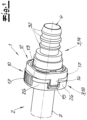
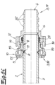
- Fig. 1 highlights the basic components of a first coupling assembly according to the invention comprising a female quick connector 1 and a complementary male member 2.
- the quick connector of this embodiment comprises several separate parts and in particular a retainer 10 and a verifier 12 which both preferably surround at least in part a main body 3 of the quick connector 1.
- the main body 3 preferentially comprises a coupling part 18 and a hose part 19 which are advantageously snapped together via a snap connection which is explained in detail further below.
- the main body 3 has a through bore 4 extending from the hose part 19 to the coupling part 18 thereby providing a fluid connection of the male member 2 with a first hose (not shown).
- the male member 2 may be an end piece of a second hose or of another component (both not shown) of a fluid line system which is not visualised as well.
- Said first hose can be connected with the hose part 19 in this embodiment by plugging it on barbed elements 32 of the hose part 19.
- the quick connector 1, the main body 3, and the hose part 19, respectively, comprises an optical verification element 13.
- the optical verification element 13 of this embodiment is a QR-code which is printed onto the hose part 19. The function of the optical verification element 13 is explained in more detail further below.
- the retainer 10 is advantageously an annular part which surrounds in circumferential direction at least section wise the main body 3 and the male member 2, respectively.
- the retainer 10 preferably has two actuating segments 17 which are preferentially arranged diametrically with respect to each other.
- the actuating segments 17 of the retainer 10 of this embodiment are designed to be actuated by two fingers and therefore have corrugated surfaces for better grip.
- the retainer 10 may comprise two covered sections 15 (the second one is not visible in Fig. 1 due to the perspective) which preferably oppose each other diametrically. The function of these covered sections 15 is explained in more detail with respect to Figs. 5A to 5D .
- the verifier 12 preferably is an annular element which surrounds the main body 3.
- the verifier 12 of this embodiment has two locking sections 14 which are arranged diametrically with respect to each other, wherein the second locking section is not visible due to the perspective. Due to the coupled state of the coupling assembly in Fig 1 , the verifier 12 is in a locking position in which the locking sections 14 of the verifier 12 engage with the covered sections 15 of the retainer 10.
- the male member 2 is fully inserted into the main body 3 and the quick connector 1, respectively, which defines a latched position of the male member 2.
- the coupled state of the coupling assembly is characterised in that the verifier 12 is in the locking position while the male member 2 is in the latched position. Said positions and the according mechanisms are explained in detail in view of Figs. 5A to 6D .
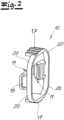
- Fig. 2 illustrates the structure of the retainer 10 and shows that the retainer 10 is basically shaped annular.
- ring sections 20 connect the covered sections 15 with the actuating segments 17 resulting in said annular shape of the retainer 10.
- Imaginary connection lines between the two covered sections 15 on the one hand and between the two actuating segments 17 on the other hand may form a cross. It is preferred that the angle between said two imaginary lines is 90°.
- the covered sections 15 of this embodiment each may correspond with a retaining element 11.
- the retaining elements 11 project radially inward for engagement with a latching element 8 of the male member 2 (see Fig. 5A ).
- the retaining elements 11 both advantageously have sloped surfaces facing axially outward for easier insertion of the male member 2.
- both actuating segments 17 of the retainer 10 move radially inward. This preferably causes a radial movement of the retaining elements 11 in radial outward direction for disengaging with the latching element 8 of the male member 2, thereby characterizing a tensioned state of the retainer 10.
- the retainer 10 preferentially acts like a spring so that the actuating segments 17 move radially outward.
- the retaining elements 11 advantageously move radially inward, thereby defining a relaxed state of the retainer 10.
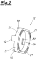
- the verifier 12 is shown in more detail in Fig. 3 .
- the verifier 12 of this embodiment comprises two intermediate segments 16 which project in axial outward direction and which are not visible in Fig. 1 since the intermediate segments 16 are covered by the actuating segments 17 of the retainer 10.
- the two intermediate segments 16 are connected with a first imaginary line as well as both looking sections 14 are connected with each other by a second imaginary line.
- both imaginary lines of the looking sections 14 and the intermediate segments 16 form a cross. It is preferred that said two imaginary lines of the verifier 12 form an angle of 90°.
- the verifier 12 further comprises in this embodiment four annular segments 21, wherein each annular segment 21 preferably connects a locking section 14 with an intermediate segment 16.
- the annular segments 21 of the verifier are rather stiff which might be realised by thicker annular segments 21 and/or by strengthening ribs as shown in Fig. 3 .
- the verifier 12 is basically moved in axial direction from a releasing position into a locking position which is explained in particular with respect to Figs. 5 and 6 .
- Fig. 4 shows a perspective view of the coupling part 18 of the main body 3.
- the coupling part 18 advantageously has a connection section extending in axial direction which preferably comprises several connection elements 27. Said connection elements 27 preferentially engage with according connection pieces 28 (see Fig 5A ) of a connection section of the hose part 19.
- the connection elements 27 and the connection pieces 28 preferably form a snap connection in order to assemble the main body 3.
- the coupling part 18 further may comprise a flange 22 having a face end 5 (see Fig. 5A ) facing axially outward.
- the coupling part 18 preferably has annular coverings 26.
- the annular coverings 26 are connected with the flange 22 forming actuating recesses 23 and preferable retaining recesses 24. While the actuating recesses 23 of this embodiment each may receive an actuating segment 17 of the retainer 10, the retaining recesses 24 preferably each receive a covered section 15 of the retainer 10 (compare with Fig. 1 ). It is very preferred that the coupling part 18 further comprises two retaining slots 25 which are arranged diametrically with respect to each other (the second retaining slot 25 is not visible due to the perspective of Fig. 4 ) and which are preferably designed to each receive a retaining element 11 of the retainer 10. It is preferred that the coupling part 18 comprises a latching section extending in axial direction. Preferentially, the latching section is disposed between the snap section and the flange 22, respectively.
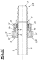
- FIG. 5A to 5D show different points of an insertion procedure of the male member 2 into the quick connector 1.
- Figs. 5A and 6A visualize an open position of the male member 2 in which the male member 2 is not yet inserted into the quick connector 1 so that the coupling assembly is in a decoupled state.
- Figs. 5B and 6B show a pre-latching position of the male member 2, while the male member 2 is in a latched position in Figs. 5C and 6C .
- Figs. 5D and 6D highlight a locking position of the verifier 12 in contrary to a releasing position of the verifier 12 in Figs. 5A to 5C and 6A to 6C .
- the figure series 5A to 5D shows longitudinal sections through the locking sections 14 and the covered sections 15, while Figs. 6A to 6D illustrate longitudinal sections through the intermediate segments 16 and the actuating segments 17.
- Fig. 5A shows an assembled state of the main body 3 and thus an engagement of the snapping elements 27 of the coupling part 18 with the snapping pieces 28 of the hose part 19.
- the snapping elements of this embodiment are shaped as radially flexible hooks which are hooked into said snapping pieces 28.
- the snapping pieces 28 are preferably window-shaped.
- the main body 3 / the hose part 19 has a hose section which is designed for engagement with a hose (not shown).
- the hose section of the main body 3 / the hose part 19 may have barbed elements 32, wherein the hose section defines a hose chamber 31.
- the male member 2 has a wall 7 and a, preferably rounded, tip 6.
- the male member 2 further comprises a latching element 8 which is formed as a groove in this embodiment.
- a sealing section 9 has an axial length L and is disposed between the latching element 8 and the tip 6.
- the sealing section 9 is designed for fluid tight engagement with a sealing element 29 within a sealing chamber 30 of the main body 3 and the coupling part 19, respectively.
- the male member 2 has an outer diameter D preferably corresponding to an inner diameter of the sealing element 29 which is an elastomeric sealing ring in this embodiment. It is preferred that the inner diameter of the hose chamber 31 corresponds to the inner diameter of the male member 2.
- the retainer 10 of Fig. 5A is in a relaxed state, wherein the verifier 12 is in a releasing position.
- the verifier 12 of this embodiment is latched onto the main body 3 in the releasing position via two rear snapping items (not shown) on the outer surface of the main body 3 / the hose part 19. It is preferred that the locking sections 14 of the verifier 12 do not cover the covered sections 15 of the retainer 10 in the releasing position.
- the locking sections 14 have a radial position which is slightly radially outward compared to the radial position of the covered sections 15, it is in general possible to move the verifier 12 in axial outward direction along a verification path and thus toward the face end 5 so that the locking sections 14 would overlap the covered sections 15, thereby defining the locking position of the verifier 12. This however is not done during the subsequent described insertion procedure of the male member 2 since the locking position of the verifier 12 disables the flexibility of the retainer 10 in radial direction so that the male member 2 could not be inserted into the quick connector 1 anymore.
- the tip 6 of Fig. 5B has passed the retaining elements 11 (but not yet the sealing element 29), thereby pushing them radially outward and defining a pre-latching position of the male member 2. Accordingly, the covered sections 15 are also moved radially outward so that the covered sections 15 now substantially have the same radial position like the locking sections 14. This in turn means that the verifier 12 is not movable along the verification path in axially outward direction anymore since the locking sections 14 would abut on the covered sections 15 in axial direction. While the retainer 10 of Fig. 5B now is in a tensioned state, the verifier 12 is still in the releasing position and cannot be moved into the locking position. Thus, the pre-latching position of the male member 2 is indicated by the verifier 12 in that the verifier 12 cannot be shifted into the locking position.
- Fig. 5C depicts a situation in which the male member 2 has been fully inserted so that the tip 6 has passed the sealing element 29. Also, the latching element 8 has reached the retaining elements 11 of the retainer 10. As a consequence, the retainer 10 changed its state from the tensioned state into the relaxed state by snapping onto the latching element 8 of the male member 2. Since the covered sections 15 moved radially inward, they do not block any more the verification path, so that the verifier 12 can be moved by a user along the verification path from the releasing position of Fig. 5C into the locking position of Fig. 5D .
- the verifier 12 of this embodiment comprises two snapping elements 33 for latching onto the retainer 10 via two according front snapping items 36 of the retainer 10 in the form of two grooves. It has to be noted that - while the male member 2 is inserted into the quick connector - the verifier 12 can only be moved along the verification path when the male member 2 has latched with the retaining elements 11.
- Fig. 6A shows the situation of the coupling assembly of Fig. 5A , wherein the coupling assembly has been rotated by 90° around the longitudinal axis thereby showing the relation between the intermediate segments 16 of the verifier 12 and the actuating segments 17 of the retainer 10.
- the actuating segments 17 are positioned slightly radially outward compared to the intermediate segments 16. This means that the verifier 12 in general could be moved axially outward since the actuating segments 17 do not block the intermediate segments 16.
- the male member 2 is partly inserted into the quick connector 1 until the tip 6 has passed the retaining elements 11 (not shown in Fig. 6B due to the rotation of the perspective) but not yet the sealing element 29.
- the male member 2 is in the pre-latching position.
- the retaining elements 11 are pushed radially outward which in turn means that the actuating segments 17 of the retainer 10 are pulled radially inward as shown in Fig. 6B .
- the actuating segments 17 abut on the intermediate segments 16 when the verifier 12 is moved axially outward. This means that also the actuating segments 17 block the verifier 12 in axial direction when the male member 2 is in the pre-latching position.
- Fig. 6C shows the fully inserted male member 2 so that the latching element 8 reached the retaining elements 11 (compare with Fig. 5C ). Since the retaining elements 11 snapped in radially inward direction, the actuating segments 17 have been pushed radially outward. Hence, the actuating segments 17 do not block anymore the intermediate segments 16 and the verifier 12, respectively.
- the optical verification element 13 is still covered by the verifier 12 in Fig. 6C . But when the verifier 12 is moved from the releasing position of Fig. 6C to the locking position of Fig. 6D , the optical verification element 13 becomes visible.
- the visible optical verification element 13 of Fig. 6D is a clear indication that the male member 2 is fully inserted. Also the actuating segments 17 cannot be actuated anymore since they are blocked in radially inward direction by the intermediate segments 16 and since the locking sections 14 of the verifier block the covered sections 15 of the retainer 10 in radial outward direction ( Fig. 5D ).
- this embodiment indicates in a clear haptic and visual manner when the male member 2 is in the latching position.
- the verifier 12 and the optical verification element 13 also indicate when the male member 2 is only in the pre-latching position.
- Two locking mechanisms of the verifier 12 lock the retainer 10 in the latching position of the male member 2 so that neither external forces can press the actuating segments 17 radially inward nor internal forces the retaining elements 11 radially outward. These two locking mechanisms support the latching mechanism of the retainer 10 resulting in a triple lock coupling assembly making it for accidentally forces nearly; - possible to release the male member 2. Instead, a user first has to move the verifier 12 axially outward along the verification path to the releasing position in order to then press the actuating segments 17 for releasing the male member 2.
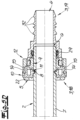
- Fig. 7 depicts a second embodiment of the invention and thus a second coupling assembly comprising a quick connector 1 and a male member 2.
- the quick connector 1 of this second embodiment comprises a main body 3, a retainer 10, and a verifier 12.
- the main body 3 of the second embodiment has a coupling part 18 and a hose part 19 which are assembled together via a snap connection comparable to the one of the first embodiment.
- the verifier 12 of the second embodiment differs compared to the first embodiment.
- the verifier 12 of the second embodiment preferably comprises an operating element 35 which can be a bead or flange protruding in radial direction for better grip in order to move the verifier 12 along the verification path.
- the verifier 12 of the second embodiment comprises at least one snapping element 33 and preferably four snapping elements 33 which are preferably located in an axially rear section of the verifier 12.
- the main body 3 / the hose part 19 of the second embodiment may comprise at least one and preferably four rear snapping items 34 which correspond to the snapping elements 33 of the verifier 12 when the verifier 12 is in the releasing position.
- the main body 3 / the hose part 19 of this embodiment comprises four axial guides 37 in the form of grooves in axial direction.
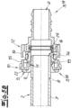
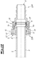
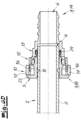
- Fig. 8 shows a longitudinal section of the second embodiment in which the male member 2 is in the latched position (retaining elements not visible in this longitudinal section comparable to Fig. 6D ), while the verifier 12 is in the locking position so that the coupling assembly is in the coupled state.
- the intermediate segments 16 of the verifier are disposed in radial direction between the actuating segment 17 of the retainer 10 and the hose part 19.
- the snapping elements 33 preferably comprise a protrusion which protrudes in radially inward direction.
- the main body 3 / the hose part 19 of this embodiment comprises at least one and preferably four front snapping items 36 which correspond with the snapping elements 33 when the verifier 12 is in the locking position.
- the rear snapping items 34 engage with the snapping elements 33 when the verifier 12 is in the releasing position. It is very preferred that the rear snapping items 34, the front snapping items 36 and the snapping elements 33 define the releasing position and the locking position, respectively.
- the protrusions of the snapping elements 33 of this embodiment also engage with the axial guides 37 so that the verifier 12 cannot be rotated along the verification path and in particular not when the verifier 12 is in the releasing position.
- connection element 1 quick connector 26 annular covering 2 male member 27 connection element 3 main body 28 connection piece 4 through bore 29 sealing element 5 face end 30 sealing chamber 6 tip 31 hose chamber 7 wall 32 barbed element 8 latching element 33 snapping element 9 sealing section 34 rear snapping item 10 retainer 35 operating element 11 retaining element 36 front snapping item 12 verifier 37 axial guide 13 optical verification element 14 covering section 15 covered section 16 intermediate segment 17 actuating segment 18 coupling part 19 hose part 20 ring section 21 annular segment 22 flange 23 actuating recess 24 retaining recess 25 retaining slot
Landscapes
- Engineering & Computer Science (AREA)
- General Engineering & Computer Science (AREA)
- Mechanical Engineering (AREA)
- Quick-Acting Or Multi-Walled Pipe Joints (AREA)
- Joints That Cut Off Fluids, And Hose Joints (AREA)
- Coupling Device And Connection With Printed Circuit (AREA)
- Details Of Connecting Devices For Male And Female Coupling (AREA)
- Fittings On The Vehicle Exterior For Carrying Loads, And Devices For Holding Or Mounting Articles (AREA)
Description
- The invention refers to a coupling assembly comprising a female quick connector and a male member for insertion into the quick connector, wherein the male member has a tip for insertion into the main body, a wall defining an inner surface and an outer surface, and a latching element on the outer surface of the wall, wherein the male member comprises a sealing section between the latching element and the tip, wherein the quick connector comprises a retainer, wherein the retainer has at least one retaining element for interacting with the latching element of the male member for retaining the male member within the main body, wherein the retainer comprises at least one actuating segment, wherein the male member is in a latching position when the latching element is latched onto the at least one retaining element, wherein the male member is in a pre-latching position when the retaining element overlaps axially with the sealing section of the male member, wherein the quick connector has a verifier, wherein the verifier is axially movable along a verification path, wherein the verification path comprises at least one locking position and at least one releasing position, wherein the verifier in axial direction is closer to the retainer in the locking position than in the releasing position. The invention also refers to a method for establishing a fluid connection comprising such a coupling assembly.
- Such a coupling assembly is known from
DE 198 22 574 C1 . This coupling assembly comprises a female quick connector, a complementary male member, an annular retainer and a verifier. The quick connector has two sealing rings for fluid tight sealing of a sealing section of the male member. The male member further comprises a latching element and a tip, wherein the sealing section is arranged between the tip and the latching element. The retainer has two retaining elements and two actuating segments. Both retaining elements are opposing each other. The same applies to both actuating segments, wherein imaginary connection lines of the actuating segments and the retaining elements form a cross in a front view. When the actuating segments are actuated, the retainer is flattened, thereby increasing the distance of the retaining elements and releasing the latching element and the male member, respectively, from a latching position. - The verifier of
DE 198 22 574 C1 defines a locking position and a releasing position, wherein the retainer is actuatable in the releasing position and not actuatable in the locking position of the verifier. These two positions are part of a verification path of the verifier in which the verifier is axially moved from the axially outward releasing position to the axially inward locking position. The verifier covers the actuating segments of the retainer in the locking position thereby inhibiting actuation of the retainer. When the male member is fully inserted and thus latched onto the retaining elements of the retainer, the latching element engages with an inner element of the verifier so that the verifier is pushed out of the quick connector in axial outward direction. This state of the verifier thus defines a releasing position. - When the retainer is actuated and the male member is pulled out, the verifier can be pushed into the quick connector again. A latching mechanism within the quick connector holds the verifier in the locking position until the male member is fully inserted and the verifier is thrown out again. Hence, the verifier of
DE 198 22 574 C1 verifies by being thrown out that the male member is fully inserted. However, it has been observed that comparable coupling assemblies might fail in certain situations in which the male member accidentally has been released from the quick connector resulting in fluid loss. -
DE 101 26 205 C1 teaches a coupling assembly comprising a female quick connector, an according male member, an annular retainer and an annular verifier. A first important difference toDE 198 22 574 C1 is that the verifier engages with the latching element of the male member in such a way that the latching element takes the verifier along the verification path until the latching element passes the retaining elements of the retainer. The male member then has reached its latching position while the verifier covers the actuating segments of the retainer which can be seen as a kind of a locking position of the verifier. When the verifier ofDE 101 26 205 C1 is moved from the releasing position to the locking position, a metal spring between the verifier and the quick connector is pressed thereby storing kinetic energy. The verifier comprises flexible actuating tabs covering the actuating segments of the retainer in the locking position. When the actuating tabs of the verifier are pushed radially inward, the actuating tabs in turn push the actuating segments of the retainer radially inward thereby releasing the male member. This then releases the stored kinetic energy of the spring so that the verifier and the male member are pushed axially outward. However, the force in order to actuate the actuating tabs ofDE 101 26 205 C1 is practically the same like the one to actuate the actuating segments ofDE 198 22 574 C1 since both are designed for the same power of human hands. This means that the same problem arises - high fluid pressures and/or material deterioration and/or improper handling of the coupling assembly might lead to a force which releases the latching element. - Another coupling assembly is known from
US 4 993 755 A . - It is therefore an object of the invention to provide a quick connector with a noticeable increased connection safety. It is a preferred object of the invention that the coupling assembly / the quick connector becomes more compact.
- This object is solved by independent claim 1, comprising a coupling assembly, comprising a female quick connector and a male member for insertion into the quick connector, wherein the quick connector comprises a main body, wherein the main body has a coupling section for insertion of the male member into the main body, wherein the main body comprises a hose section for connection with a hose or pipe, wherein the coupling section is connected to the hose section via a through bore of the main body, wherein the main body comprises a face end which is allocated to the coupling section,
- wherein the male member has a tip for insertion into the main body, a wall defining an inner surface and an outer surface, and a latching element on the outer surface of the wall, wherein the male member comprises a sealing section between the latching element and the tip, wherein the male member has a longitudinal axis which defines an axial, a radial and a circumferential direction of the coupling assembly and the coupling section, respectively,
- wherein the quick connector comprises a retainer, wherein the retainer has at least one retaining element for interacting with the latching element of the male member for retaining the male member within the main body, wherein the retainer comprises at least one actuating segment for actuating the retainer for unlatching the latching element and releasing the male member from the main body, wherein the male member is in a latching position when the latching element is latched on to the at least one retaining element, wherein the male member is in a pre-latching position when the retaining element overlaps axially with the sealing section of the male member,
- wherein the quick connector has a verifier, wherein the verifier is axially movable along a verification path, wherein the verification path comprises at least one locking position and at least one releasing position, wherein the verifier in axial direction is closer to the retainer in the locking position than in the releasing position, wherein the verifier is kept by the coupling assembly in the locking position when the male member is in the latching position,
- wherein the coupling assembly is constructed so that the verifier in the locking position limits a movement of a section of the retainer in radial direction, so that the retainer is not actuatable in the locking position of the verifier but actuatable in the releasing position of the verifier.
- The invention is initially based on the finding that, over the lifetime of a vehicle, situations may occur in which high fluid pressures and/or material deterioration and/or improper handling of the coupling assembly lead to a force which releases the latching element. For example, very high fluid pressures may accidentally arise in fluid lines which press the male member axially outward against the retainer. This in turn can result in a high force onto deteriorated retaining elements which are spread apart thereby releasing the male member and causing fatal fluid loss.
-
DE 198 22 574 C1 does not teach to keep the verifier in the locking position by the coupling assembly when the male member is in the latching position. Instead, the verifier is thrown out of the main body when the male member reaches the latching position. If the coupling assembly ofDE 198 22 574 would be constructed in such a way that the verifier is kept by the coupling assembly in the locking position when the male member is in the latching position, the verifier would lose its verification function.DE 101 26 205 C1 does not describe that the retainer is not actuatable in the locking position of the verifier. It is rather disclosed that the retainer must be actuatable in the locking position of the verifier since otherwise the verifier and thus the male member cannot be released anymore. - It was found that when the male member is in the latching position while the verifier is kept by the coupling assembly in the locking position so that the retainer is not actuatable, a double lock function occurs. This means that accidentally high forces have to work against the retainer and the verifier which significantly increases the force threshold to release the male member. Accidentally forces now must be much higher making it nearly impossible to release the male member so that said object is solved.
- It is preferred that the male member is in a released position when the male member does not overlap axially with the retaining element / the retaining elements. Preferably, the coupling assembly is in a decoupled state when the male member is in the released position. The coupling assembly is preferentially in a pre-coupled state when the male member is in the pre-latching position. It is preferred that the coupling assembly is in a latched state when the male member is in the latching position while the verifier is in the releasing position. According to a preferable embodiment, the coupling assembly is in a coupled state if the male member is in the latching position while the verifier is in the locking position. It is advantageous that the retainer is constructed so that the retainer acts like a spring when the actuating element / the actuating elements are pressed. The retainer preferentially is in a tensioned state while the actuating element / the actuating elements is / are pressed. Preferably, the retainer is in a relaxed state when the actuating element / the actuating elements is / are not pressed.
- The term "actuatable" preferably means that the retainer / the verifier can be manipulated manually by fingers of a human hand. The same applies to the word "movable". The quick connector might be straight or angled. If the quick connector is angled, a direction of the longitudinal axis of the hose section is different to the direction of the longitudinal axis of the coupling section. If the quick connector is angled, the longitudinal axis of the male member corresponds to the longitudinal axis of the coupling section but not to the longitudinal axis of the hose section.
- It is very preferable that the retainer has an annular shape. This effects that the retainer has more elastic stability compared to, for example, to a U-shaped retainer which contributes to a higher connection safety. The annular shape also promotes a smaller probability of a loss of the retainer. If the retainer has an annular shape, the retainer might be easier to actuate. It is preferred that the retainer comprises at least two actuating segments. Preferentially, the retainer has at least two retaining elements. The at least one retaining element preferably protrudes radially inward for engaging with the latching element of the male member. It is preferred that the at least one retaining element comprises a sloped surface facing axially outward for easier insertion of the male member. Preferably, the retaining elements oppose each other with respect to the annular shape of the retainer. It is advantageous that the actuating segments oppose each other with respect to the annular shape of the retainer. It is preferred that, along the circumferential direction of the retainer, the retaining elements and the actuating segments are disposed in an alternating manner on the retainer. Preferably, a first imaginary line connects the retaining elements, while a second imaginary line connects the actuating segments. According to a very preferred embodiment, the first and second imaginary lines form a cross in a front view of the retainer. Advantageously, said two imaginary lines enclose an angle of 70° to 110° and preferably of 80° to 100° between each other in a front view. The retainer preferentially comprises four ring sections. It is preferred that each ring section connects a retaining element with an actuating segment.
- According to the invention, the retainer comprises at least one covered section and preferentially two covered sections. The at least one covered section is preferably arranged radially outward of the at least one retaining element. It is preferred that a covered section is allocated to each retaining element. The at least one covered section may form an outer surface of the retainer. Preferably, the at least one covered section is designed to be covered by a / the according covering section of the verifier when the verifier is in the locking position.
- The verifier advantageously has an annular shape. If the verifier has an annular shape compared to, for example, a U-shaped verifier, the verifier can be constructed more rigid which makes the verifier capable of withstanding higher forces. Accordingly, the verifier provides a stronger locking function and thus a higher connection safety. It is very preferred that the verifier comprises at least one and preferably two covering sections and/or at least one and preferably two intermediate segments. It is preferred that the at least one covering section and/or the at least one intermediate segment extends and preferably protrudes in axial direction and in particular in axially outward direction. The axial length of the at least one axially protruding covering section / intermediate segment is at least a fourth, preferably a third and most preferably a half of the axial length of the verifier.
- Preferentially, the covering sections and the intermediate segments are arranged on the verifier in an alternating manner in circumferential direction. It is preferred that the two covering sections / the two intermediate segments oppose each other with respect to the annular shape of the verifier. The covering sections may be connected with a third imaginary line while the intermediate segments may be connected with a fourth imaginary line. Preferably, the third imaginary line and the fourth imaginary line form a cross in a front view of the verifier. It is very preferred that the third imaginary line and the fourth imaginary line enclose an angle of 70° to 110° and preferably 80° to 100° between each other. According to an advantageous embodiment, the verifier comprises four annular segments. It is preferred that each annular segment connects a covering section with an intermediate segment.
- Preferentially, the verifier is constructed so that the verifier is stiff in a radial direction and preferably in all radial directions. According to a particular embodiment, the annular segments each comprise a base rib and a strengthening rib, for making the verifier stiff.
- The verifier may comprise at least one snapping element, preferably two or four snapping elements, for snapping onto the retainer and/or onto the main body in the locking position and/or in the releasing position. The main body preferably has at least one rear snapping item, preferentially two or four rear snapping items, corresponding to the at least one snapping element of the verifier. It is very preferred that the at least one rear snapping item, for example a groove, defines a particular / the releasing position of the verifier in which the verifier is snapped onto the main body. According to a very preferred embodiment, the main body comprises at least one front snapping item, preferably at least two or four front snapping items, corresponding to the at least one snapping element of the verifier. It is very advantageous that the at least one front snapping item, for example a groove, defines a particular / the locking position of the verifier in which the verifier is snapped onto the main body.
- According to another embodiment, the retainer comprises at least one front snapping item, preferably at least two or four front snapping items, corresponding to the at least one snapping element of the verifier. It is possible that the at least one front snapping item of the retainer, for example a groove, defines a particular / the locking position of the verifier in which the verifier is snapped onto the retainer.
- It is very preferred that the verifier comprises an operating element for moving the verifier in axial direction. The operating element can be a corrugated section of the outer surface of the verifier, a bead and/or a flange protruding in radially outward direction for better grip. The main body / the hose part preferably comprises at least one axial guide and in particular two or four axial guides for guiding the verifier along the verification path. The at least one axial guide advantageously prohibits a rotational movement of the verifier along the verification path / when the verifier is in the releasing position. The at least one axial guide may be a groove.
- Preferentially, the coupling assembly is constructed so that the verifier - during a movement from the releasing position to the locking position - moves away from the hose section (axially outward). This provides a more compact quick connector in axial direction. It is preferred that the retainer is arranged in axial direction between the face end of the main body and the verifier in the locking position. The retainer preferably does not comprise the face end of the main body and the quick connector, respectively. The term "axially outward" advantageously means that the verifier in the releasing position and the face end of the main body are arranged in the same axial half of the quick connector so that the axially outward movement is not directed to the axial middle of the quick connector.
- It is very preferred that the coupling assembly is constructed so that the verifier in the locking position, and preferably also in the releasing position, is not actuatable in radial direction. If the verifier is not actuatable in radial direction in the locking position, the probability of an accidental manual release is much smaller. This also applies with respect to accidental high fluid pressures. The effect of this feature is thus a stronger locking function which increases connection safety. Preferentially, the verifier is stiff so that human fingers cannot deform the verifier in radial direction. It is possible that the main body / the retainer supports the verifier in the locking position so that human fingers cannot deform the verifier in radial direction.
- According to a preferred embodiment, the coupling assembly is constructed so that the verifier can be moved to the locking position when the male member is in the latching position, wherein the verifier cannot be moved to the locking position when the male member is in the pre-latching position. This provides a haptic verification of the latching position of the male member and thus increases the connection safety. It is preferred that the coupling assembly is constructed so that the verifier can be moved to the locking position when the male member is in the released position. Preferably, the verifier abuts on the retainer in axial direction before reaching the locking position when the male member is in the pre-latching position. The verifier preferentially does not abut on the retainer in axial direction during a movement from the releasing position to the locking position when the male member is in the latching position.
- Preferably, the retainer is a separate element with respect to the main body and the face end, respectively. This effects a higher flexibility of the retainer so that in particular no long axial webs for flexibility are needed which provides a more compact coupling section and thus a more compact quick connector. According to an advantageous embodiment, the retainer is a separate element with respect to the coupling part and the quick connector, respectively. The term "separate" preferably means that there is no bonding or integral connection between the retainer and the coupling part / the main body / the quick connector / the face end.
- According to a very preferred embodiment, the latching element of the male member is a groove. This provides a more compact male member in radial direction and thus a more compact quick connector. It is preferred that the inner surface of the wall of the male member at the tip is cylindrical. The groove preferably comprises an axial outer wall and an axial inner wall. Preferentially, the axial inner wall of the male member is sloped in a longitudinal section of the male member. Preferably, at least a section of the axial outer wall of the groove member extends in radial direction for latching onto the retaining element / the retaining elements of the retainer.
- It is advantageous that the sealing section of the male member has a length L in the axial direction, wherein the sealing section has an outer diameter D, wherein the ratio of L to D is at the most 2.2, preferably at the most 1.9 and most preferably at the most 1.6. This provides a more compact male member in axial direction and thus a more compact quick connector in axial direction.
- It is very preferable that the quick connector / the main body comprises an optical verification element, wherein it is preferred that the optical verification element is visible / readable when the verifier is in one of both the locking position and the releasing position, while the optical verification element is not visible / readable when the verifier is in the other one of both the locking position and the releasing position. This effects a visual indication of the latching position of the male member and thus increases connection safety. The coupling assembly is preferably constructed so that the optical verification element is covered by the verifier when the verifier is in one of both the releasing position and the locking position. Advantageously, the optical verification element is not covered by the verifier when the verifier is in the other one of both the locking position and the releasing position. It is preferred that the optical verification element is visible / readable when the verifier is in the locking position. Preferentially, the optical verification element is not visible / readable when the verifier is in the releasing position.
- It is very preferred that the optical verification element is machine-readable. The optical verification element can be a QR-code or a barcode. According to a preferred embodiment, the optical verification element is fixed / printed on an outer surface of the main body / the coupling part / the hose part / the retainer.
- It is very preferred that the coupling assembly is constructed so that the verifier in the locking position restricts a movement of a section of the retainer in a radial inward direction and/or restricts a movement of a section of the retainer in a radial outward direction. This provides the double lock or even the triple lock function of the coupling assembly and thus increases connection safety. It is preferred that the at least one actuating segment of the verifier abuts on the at least one intermediate segment of the verifier when the verifier is in the locking position and when the actuating segment / the actuating segments are pressed. Advantageously, the at least one covered section of the retainer abuts in radial direction, preferably in radially outward direction, on the at least one covering section when the verifier is in the locking position and when the at least one actuating segment is pressed.
- Very preferentially, the coupling assembly is constructed to that the verifier has at least one covering section which covers a covered section of the retainer in radial direction when the verifier is in the locking position. This effects a locking function of the verifier and thus increases connection safety. It is preferred that the coupling assembly is constructed so that the covering section does not cover the covered section of the retainer in radial direction when the verifier is in the releasing position. In particular, at least two sections / the two covering sections of the verifier may cover according sections / the covered sections of the retainer when the verifier is in the locking position.
- According to an advantageous embodiment, the coupling assembly is constructed so that the verifier has at least one intermediate segment which is positioned in radial direction between the at least one actuating segment of the retainer and the main body / the male member when the verifier is in the locking position. This provides a locking function of the verifier and increases connection safety. It is preferred that the intermediate segment is not disposed between the actuating segment and the main body / the male member when the verifier is in the releasing position. It is advantageous that at least two segments / the two intermediate segments of the verifier are each disposed between according sections / the two actuating segments when the verifier is in the locking position.
- Preferably, the main body comprises a coupling part and a hose part, wherein the coupling part is fixed to the hose part, preferably in a form-fitting and/or force-fitting manner and/or by material bonding. This effects that the main body can receive an annular shaped retainer so that the retainer is hold captively on the main body. This also contributes to the compactness of the quick connector. Preferably, the coupling part comprises the face end. It is preferred that the hose part comprises the hose section. It is preferred that the coupling part and the hose part are connected by a snap connection. The coupling part may comprise an axial connection section which preferably comprises at least one connection element and preferably at least two connection elements. The hose part may have an axial connection segment which preferably comprises at least one connection piece and preferably at least two connection pieces for engaging with the connection element / the connection elements of the coupling part. It is preferred that the coupling part has four connection elements while the hose part comprises four corresponding connection pieces.
- The quick connector / the main body / the hose part preferably encompasses a sealing element in radial direction. The sealing element can be a sealing ring which may comprise an elastomer. It is preferred that the coupling part and the hose part enclose the sealing element in axial direction. Preferentially, the coupling part encloses the retainer in axial direction. The sealing element preferably engages with the sealing section of the male member. The material bonding can be achieved by glueing and in particular welding (laser welding or friction welding).
- It is very preferred that the coupling assembly is constructed so that the verifier does not contact the male member during insertion of the male member into the quick connector and the main body, respectively. This simplifies the structure of the verifier / retainer / main body / coupling assembly and thus provides more compactness. In particular, the coupling assembly can be constructed so that the verifier is not expanded in radial direction during the whole insertion process of the male member into the main body. It is very preferred that the male member in the pre-latching position deforms / expands the retainer in radial direction and in particular moves the retaining element / spreads the retaining elements apart from each other. The radial expansion of the retainer in the pre-latching position of the male member preferably results in that the verifier abuts on the retainer in axial direction before the verifier reaches the locking position. It is preferred that the retainer is deformed by the male member in the pre-latching position so that the verifier cannot be moved to the locking position.
- The above-mentioned object is solved by
method claim 13, comprising a method for establishing a fluid connection method for establishing a fluid connection comprising a coupling assembly having a female quick connector and a male member for insertion into the quick connector, in particular comprising a coupling assembly according to the invention, wherein the quick connector comprises a main body, wherein the main body has a coupling section for insertion of the male member into the main body, wherein the main body comprises a hose section for connection with a hose or pipe, wherein the coupling section is connected to the hose section via a through bore of the main body, wherein the main body comprises a face end which is allocated to the coupling section, - wherein the male member has a tip for insertion into the main body, a wall defining an inner surface and an outer surface, and a latching element on the outer surface of the wall, wherein the male member comprises a sealing section between the latching element and the tip, wherein the male member has a longitudinal axis which defines an axial, a radial and a circumferential direction of the coupling assembly and the coupling section, respectively,
- wherein the quick connector comprises a retainer, wherein the retainer has at least one retaining element for interacting with the latching element of the male member for retaining the male member within the main body, wherein the retainer comprises at least one actuating segment for actuating the retainer for unlatching the latching element and releasing the male member from the main body, wherein the male member is in a latching position when the latching element is latched onto the at least one retaining element, wherein the male member is in a pre-latching position when the retaining element overlaps axially with the sealing section of the male member,
- wherein the quick connector has a verifier, wherein the verifier is axially movable along a verification path, wherein the verification path comprises at least one locking position and at least one releasing position, wherein the verifier in axial direction is closer to the retainer in the locking position than in the releasing position, wherein the verifier is kept by the coupling assembly in the locking position when the male member is in the latching position,
- wherein the verifier in the locking position limits a movement of a section of the retainer in radial direction, so that the retainer is not actuatable in the locking position of the verifier but actuatable in the releasing position of the verifier.
- Two exemplary embodiments of the invention are explained in more detail below with reference to several schematic figures. It is shown in
- Fig. 1
- a perspective view of a first coupling assembly according to the invention,
- Fig. 2
- a perspective view of a retainer of the coupling assembly of
Fig. 1 , - Fig. 3
- a perspective view of a verifier of the coupling assembly of
Fig. 1 , - Fig. 4
- a perspective view of a coupling part of the coupling assembly of
Fig. 1 , - Fig. 5A-D
- a series of longitudinal sections of the coupling assembly of
Fig. 1 at different points of the insertion procedure of a male member, - Fig. 6A-D
- a second series of longitudinal sections of the coupling assembly in which the longitudinal sections have been rotated by 90° around the longitudinal axis compared to
Fig. 5A-D , - Fig. 7
- a perspective view of a second coupling assembly according to the invention, and
- Fig. 8
- a longitudinal section of the second coupling assembly of
Fig. 7 . -
Fig. 1 highlights the basic components of a first coupling assembly according to the invention comprising a female quick connector 1 and a complementarymale member 2. The quick connector of this embodiment comprises several separate parts and in particular aretainer 10 and averifier 12 which both preferably surround at least in part a main body 3 of the quick connector 1. The main body 3 preferentially comprises acoupling part 18 and ahose part 19 which are advantageously snapped together via a snap connection which is explained in detail further below. - The main body 3 has a through
bore 4 extending from thehose part 19 to thecoupling part 18 thereby providing a fluid connection of themale member 2 with a first hose (not shown). Themale member 2 may be an end piece of a second hose or of another component (both not shown) of a fluid line system which is not visualised as well. Said first hose can be connected with thehose part 19 in this embodiment by plugging it onbarbed elements 32 of thehose part 19. - As can be seen in
Fig. 1 , it is preferred that the quick connector 1, the main body 3, and thehose part 19, respectively, comprises anoptical verification element 13. Theoptical verification element 13 of this embodiment is a QR-code which is printed onto thehose part 19. The function of theoptical verification element 13 is explained in more detail further below. - The
retainer 10 is advantageously an annular part which surrounds in circumferential direction at least section wise the main body 3 and themale member 2, respectively. Theretainer 10 preferably has two actuatingsegments 17 which are preferentially arranged diametrically with respect to each other. Theactuating segments 17 of theretainer 10 of this embodiment are designed to be actuated by two fingers and therefore have corrugated surfaces for better grip. Theretainer 10 may comprise two covered sections 15 (the second one is not visible inFig. 1 due to the perspective) which preferably oppose each other diametrically. The function of these coveredsections 15 is explained in more detail with respect toFigs. 5A to 5D . - Still referring to
Fig. 1 , theverifier 12 preferably is an annular element which surrounds the main body 3. Theverifier 12 of this embodiment has two lockingsections 14 which are arranged diametrically with respect to each other, wherein the second locking section is not visible due to the perspective. Due to the coupled state of the coupling assembly inFig 1 , theverifier 12 is in a locking position in which the lockingsections 14 of theverifier 12 engage with the coveredsections 15 of theretainer 10. Themale member 2 is fully inserted into the main body 3 and the quick connector 1, respectively, which defines a latched position of themale member 2. Thus, the coupled state of the coupling assembly is characterised in that theverifier 12 is in the locking position while themale member 2 is in the latched position. Said positions and the according mechanisms are explained in detail in view ofFigs. 5A to 6D . -
Fig. 2 illustrates the structure of theretainer 10 and shows that theretainer 10 is basically shaped annular. In particular,ring sections 20 connect the coveredsections 15 with theactuating segments 17 resulting in said annular shape of theretainer 10. Imaginary connection lines between the two coveredsections 15 on the one hand and between the twoactuating segments 17 on the other hand may form a cross. It is preferred that the angle between said two imaginary lines is 90°. The coveredsections 15 of this embodiment each may correspond with a retainingelement 11. Preferentially, the retainingelements 11 project radially inward for engagement with a latchingelement 8 of the male member 2 (seeFig. 5A ). The retainingelements 11 both advantageously have sloped surfaces facing axially outward for easier insertion of themale member 2. - When the
actuating segments 17 of theretainer 10 are pressed, both actuatingsegments 17 move radially inward. This preferably causes a radial movement of the retainingelements 11 in radial outward direction for disengaging with the latchingelement 8 of themale member 2, thereby characterizing a tensioned state of theretainer 10. When theactuating segments 17 are not pressed anymore, theretainer 10 preferentially acts like a spring so that theactuating segments 17 move radially outward. At the same time, the retainingelements 11 advantageously move radially inward, thereby defining a relaxed state of theretainer 10. - The
verifier 12 is shown in more detail inFig. 3 . In particular, theverifier 12 of this embodiment comprises twointermediate segments 16 which project in axial outward direction and which are not visible inFig. 1 since theintermediate segments 16 are covered by theactuating segments 17 of theretainer 10. The twointermediate segments 16 are connected with a first imaginary line as well as both lookingsections 14 are connected with each other by a second imaginary line. In this embodiment, both imaginary lines of the lookingsections 14 and theintermediate segments 16 form a cross. It is preferred that said two imaginary lines of theverifier 12 form an angle of 90°. Theverifier 12 further comprises in this embodiment fourannular segments 21, wherein eachannular segment 21 preferably connects alocking section 14 with anintermediate segment 16. In contrast to thering sections 20retainer 10, theannular segments 21 of the verifier are rather stiff which might be realised by thickerannular segments 21 and/or by strengthening ribs as shown inFig. 3 . Theverifier 12 is basically moved in axial direction from a releasing position into a locking position which is explained in particular with respect toFigs. 5 and6 . -
Fig. 4 shows a perspective view of thecoupling part 18 of the main body 3. Thecoupling part 18 advantageously has a connection section extending in axial direction which preferably comprisesseveral connection elements 27. Saidconnection elements 27 preferentially engage with according connection pieces 28 (seeFig 5A ) of a connection section of thehose part 19. Theconnection elements 27 and theconnection pieces 28 preferably form a snap connection in order to assemble the main body 3. Thecoupling part 18 further may comprise aflange 22 having a face end 5 (seeFig. 5A ) facing axially outward. Thecoupling part 18 preferably hasannular coverings 26. Preferentially, theannular coverings 26 are connected with theflange 22 forming actuating recesses 23 and preferable retaining recesses 24. While the actuating recesses 23 of this embodiment each may receive anactuating segment 17 of theretainer 10, the retaining recesses 24 preferably each receive a coveredsection 15 of the retainer 10 (compare withFig. 1 ). It is very preferred that thecoupling part 18 further comprises two retainingslots 25 which are arranged diametrically with respect to each other (thesecond retaining slot 25 is not visible due to the perspective ofFig. 4 ) and which are preferably designed to each receive a retainingelement 11 of theretainer 10. It is preferred that thecoupling part 18 comprises a latching section extending in axial direction. Preferentially, the latching section is disposed between the snap section and theflange 22, respectively. - The coupling mechanism of the coupling assembly is shown in two series of
Figs. 5A to 5D and6A to 6D . Both series show different points of an insertion procedure of themale member 2 into the quick connector 1. In particular,Figs. 5A and6A visualize an open position of themale member 2 in which themale member 2 is not yet inserted into the quick connector 1 so that the coupling assembly is in a decoupled state.Figs. 5B and6B show a pre-latching position of themale member 2, while themale member 2 is in a latched position inFigs. 5C and6C .Figs. 5D and6D highlight a locking position of theverifier 12 in contrary to a releasing position of theverifier 12 inFigs. 5A to 5C and6A to 6C . The figure series 5A to 5D shows longitudinal sections through the lockingsections 14 and the coveredsections 15, whileFigs. 6A to 6D illustrate longitudinal sections through theintermediate segments 16 and theactuating segments 17. -
Fig. 5A shows an assembled state of the main body 3 and thus an engagement of the snappingelements 27 of thecoupling part 18 with the snappingpieces 28 of thehose part 19. The snapping elements of this embodiment are shaped as radially flexible hooks which are hooked into said snappingpieces 28. The snappingpieces 28 are preferably window-shaped. The main body 3 / thehose part 19 has a hose section which is designed for engagement with a hose (not shown). For example, the hose section of the main body 3 / thehose part 19 may havebarbed elements 32, wherein the hose section defines ahose chamber 31. Themale member 2 ofFig. 5A has not yet been inserted into the quick connector 1 so that themale member 2 is in the open position and that the coupling assembly is in the decoupled state. Themale member 2 has awall 7 and a, preferably rounded,tip 6. Themale member 2 further comprises a latchingelement 8 which is formed as a groove in this embodiment. Asealing section 9 has an axial length L and is disposed between the latchingelement 8 and thetip 6. Thesealing section 9 is designed for fluid tight engagement with a sealingelement 29 within a sealingchamber 30 of the main body 3 and thecoupling part 19, respectively. In particular, themale member 2 has an outer diameter D preferably corresponding to an inner diameter of the sealingelement 29 which is an elastomeric sealing ring in this embodiment. It is preferred that the inner diameter of thehose chamber 31 corresponds to the inner diameter of themale member 2. - It has to be noted that the
retainer 10 ofFig. 5A is in a relaxed state, wherein theverifier 12 is in a releasing position. Theverifier 12 of this embodiment is latched onto the main body 3 in the releasing position via two rear snapping items (not shown) on the outer surface of the main body 3 / thehose part 19. It is preferred that the lockingsections 14 of theverifier 12 do not cover the coveredsections 15 of theretainer 10 in the releasing position. Since the lockingsections 14 have a radial position which is slightly radially outward compared to the radial position of the coveredsections 15, it is in general possible to move theverifier 12 in axial outward direction along a verification path and thus toward theface end 5 so that the lockingsections 14 would overlap the coveredsections 15, thereby defining the locking position of theverifier 12. This however is not done during the subsequent described insertion procedure of themale member 2 since the locking position of theverifier 12 disables the flexibility of theretainer 10 in radial direction so that themale member 2 could not be inserted into the quick connector 1 anymore. - The
tip 6 ofFig. 5B has passed the retaining elements 11 (but not yet the sealing element 29), thereby pushing them radially outward and defining a pre-latching position of themale member 2. Accordingly, the coveredsections 15 are also moved radially outward so that the coveredsections 15 now substantially have the same radial position like the lockingsections 14. This in turn means that theverifier 12 is not movable along the verification path in axially outward direction anymore since the lockingsections 14 would abut on the coveredsections 15 in axial direction. While theretainer 10 ofFig. 5B now is in a tensioned state, theverifier 12 is still in the releasing position and cannot be moved into the locking position. Thus, the pre-latching position of themale member 2 is indicated by theverifier 12 in that theverifier 12 cannot be shifted into the locking position. -
Fig. 5C depicts a situation in which themale member 2 has been fully inserted so that thetip 6 has passed the sealingelement 29. Also, the latchingelement 8 has reached the retainingelements 11 of theretainer 10. As a consequence, theretainer 10 changed its state from the tensioned state into the relaxed state by snapping onto the latchingelement 8 of themale member 2. Since the coveredsections 15 moved radially inward, they do not block any more the verification path, so that theverifier 12 can be moved by a user along the verification path from the releasing position ofFig. 5C into the locking position ofFig. 5D . Theverifier 12 of this embodiment comprises two snappingelements 33 for latching onto theretainer 10 via two accordingfront snapping items 36 of theretainer 10 in the form of two grooves. It has to be noted that - while themale member 2 is inserted into the quick connector - theverifier 12 can only be moved along the verification path when themale member 2 has latched with the retainingelements 11. -
Fig. 6A shows the situation of the coupling assembly ofFig. 5A , wherein the coupling assembly has been rotated by 90° around the longitudinal axis thereby showing the relation between theintermediate segments 16 of theverifier 12 and theactuating segments 17 of theretainer 10. In the decoupled state of the coupling assembly ofFig. 6A , theactuating segments 17 are positioned slightly radially outward compared to theintermediate segments 16. This means that theverifier 12 in general could be moved axially outward since theactuating segments 17 do not block theintermediate segments 16. - According to
Fig. 6B , themale member 2 is partly inserted into the quick connector 1 until thetip 6 has passed the retaining elements 11 (not shown inFig. 6B due to the rotation of the perspective) but not yet the sealingelement 29. Here, themale member 2 is in the pre-latching position. As already described with respect toFig. 5B , the retainingelements 11 are pushed radially outward which in turn means that theactuating segments 17 of theretainer 10 are pulled radially inward as shown inFig. 6B . Now, theactuating segments 17 abut on theintermediate segments 16 when theverifier 12 is moved axially outward. This means that also theactuating segments 17 block theverifier 12 in axial direction when themale member 2 is in the pre-latching position. -
Fig. 6C shows the fully insertedmale member 2 so that the latchingelement 8 reached the retaining elements 11 (compare withFig. 5C ). Since the retainingelements 11 snapped in radially inward direction, theactuating segments 17 have been pushed radially outward. Hence, theactuating segments 17 do not block anymore theintermediate segments 16 and theverifier 12, respectively. - The
optical verification element 13 is still covered by theverifier 12 inFig. 6C . But when theverifier 12 is moved from the releasing position ofFig. 6C to the locking position ofFig. 6D , theoptical verification element 13 becomes visible. The visibleoptical verification element 13 ofFig. 6D is a clear indication that themale member 2 is fully inserted. Also theactuating segments 17 cannot be actuated anymore since they are blocked in radially inward direction by theintermediate segments 16 and since the lockingsections 14 of the verifier block the coveredsections 15 of theretainer 10 in radial outward direction (Fig. 5D ). - Thus, this embodiment indicates in a clear haptic and visual manner when the
male member 2 is in the latching position. Theverifier 12 and theoptical verification element 13 also indicate when themale member 2 is only in the pre-latching position. Two locking mechanisms of theverifier 12 lock theretainer 10 in the latching position of themale member 2 so that neither external forces can press theactuating segments 17 radially inward nor internal forces the retainingelements 11 radially outward. These two locking mechanisms support the latching mechanism of theretainer 10 resulting in a triple lock coupling assembly making it for accidentally forces nearly; - possible to release themale member 2. Instead, a user first has to move theverifier 12 axially outward along the verification path to the releasing position in order to then press theactuating segments 17 for releasing themale member 2. -
Fig. 7 depicts a second embodiment of the invention and thus a second coupling assembly comprising a quick connector 1 and amale member 2. The quick connector 1 of this second embodiment comprises a main body 3, aretainer 10, and averifier 12. The main body 3 of the second embodiment has acoupling part 18 and ahose part 19 which are assembled together via a snap connection comparable to the one of the first embodiment. - While the
retainer 10 of the second embodiment is more or less the same like theretainer 10 of the first embodiment, theverifier 12 of the second embodiment differs compared to the first embodiment. In particular, theverifier 12 of the second embodiment preferably comprises an operatingelement 35 which can be a bead or flange protruding in radial direction for better grip in order to move theverifier 12 along the verification path. Theverifier 12 of the second embodiment comprises at least one snappingelement 33 and preferably four snappingelements 33 which are preferably located in an axially rear section of theverifier 12. The main body 3 / thehose part 19 of the second embodiment may comprise at least one and preferably fourrear snapping items 34 which correspond to the snappingelements 33 of theverifier 12 when theverifier 12 is in the releasing position. The main body 3 / thehose part 19 of this embodiment comprises fouraxial guides 37 in the form of grooves in axial direction. -
Fig. 8 shows a longitudinal section of the second embodiment in which themale member 2 is in the latched position (retaining elements not visible in this longitudinal section comparable toFig. 6D ), while theverifier 12 is in the locking position so that the coupling assembly is in the coupled state. In particular, theintermediate segments 16 of the verifier are disposed in radial direction between the actuatingsegment 17 of theretainer 10 and thehose part 19.Fig. 8 highlights that the snappingelements 33 preferably comprise a protrusion which protrudes in radially inward direction. The main body 3 / thehose part 19 of this embodiment comprises at least one and preferably fourfront snapping items 36 which correspond with the snappingelements 33 when theverifier 12 is in the locking position. Likewise, therear snapping items 34 engage with the snappingelements 33 when theverifier 12 is in the releasing position. It is very preferred that therear snapping items 34, thefront snapping items 36 and the snappingelements 33 define the releasing position and the locking position, respectively. The protrusions of the snappingelements 33 of this embodiment also engage with theaxial guides 37 so that theverifier 12 cannot be rotated along the verification path and in particular not when theverifier 12 is in the releasing position. -
1 quick connector 26 annular covering 2 male member 27 connection element 3 main body 28 connection piece 4 through bore 29 sealing element 5 face end 30 sealing chamber 6 tip 31 hose chamber 7 wall 32 barbed element 8 latching element 33 snapping element 9 sealing section 34 rear snapping item 10 retainer 35 operating element 11 retaining element 36 front snapping item 12 verifier 37 axial guide 13 optical verification element 14 covering section 15 covered section 16 intermediate segment 17 actuating segment 18 coupling part 19 hose part 20 ring section 21 annular segment 22 flange 23 actuating recess 24 retaining recess 25 retaining slot
Claims (13)
- Coupling assembly, comprising a female quick connector (1) and a male member (2) for insertion into the quick connector (1), wherein the quick connector (1) comprises a main body (3), wherein the main body (3) has a coupling section for insertion of the male member (2) into the main body (3), wherein the main body (3) comprises a hose section for connection with a hose or pipe, wherein the coupling section is connected to the hose section via a through bore (4) of the main body (3), wherein the main body (3) comprises a face end (5) which is allocated to the coupling section,wherein the male member (2) has a tip (6) for insertion into the main body (3), a wall (7) defining an inner surface and an outer surface, and a latching element (8) on the outer surface of the wall (7), wherein the male member (2) comprises a sealing section (9) between the latching element (8) and the tip (6), wherein the male member (2) has a longitudinal axis which defines an axial, a radial and a circumferential direction of the coupling assembly and the coupling section, respectively,wherein the quick connector (1) comprises a retainer (10), wherein the retainer (10) has at least two retaining elements (11) for interacting with the latching element (8) of the male member (2) for retaining the male member (2) within the main body (3), wherein the retainer (10) comprises at least two actuating segments (17) for actuating the retainer (10) for unlatching the latching element (8) and releasing the male member (2) from the main body (3), wherein the male member (2) is in a latching position when the latching element (8) is latched onto the at least two retaining elements (11), wherein the male member (2) is in a pre-latching position when the retaining elements (11) overlap axially with the sealing section (9) of the male member (2),wherein the quick connector (1) has a verifier (12), wherein the verifier (12) is axially movable along a verification path, wherein the verification path comprises at least one locking position and at least one releasing position, wherein the verifier (12) in axial direction is closer to the retainer (10) in the locking position than in the releasing position, wherein the verifier (12) is kept by the coupling assembly in the locking position when the male member (2) is in the latching position, whereinthe verifier (12) in the locking position limits a movement of a section of the retainer (10) in radial direction, so that the retainer (10) is not actuatable in the locking position of the verifier (12) but actuatable in the releasing position of the verifier (12), wherein the coupling assembly is constructed so that the verifier (12) is not expanded in radial direction during the whole insertion process of the male member (2) into the main body (3),wherein the verifier (12) has at least one covering section (14) which covers a covered section (15) of the retainer (10) in radial direction when the verifier (12) is in the locking position,characterised in that the coupling assembly is constructed so that, when the actuating segments (17) of the retainer (10) are pressed, both actuating segments (17) move radially inward, wherein this causes a radial movement of the retaining elements (11) in radial outward direction for disengaging with the latching element (8) of the male member (2), thereby characterizing a tensioned state of the retainer (10).
- Coupling assembly according to claim 1, wherein the retainer (10) and/or the verifier (12) has an annular shape.
- Coupling assembly according to claim 1 or 2, wherein the coupling assembly is constructed so that the verifier (12) - during a movement from the releasing position to the locking position - moves away from the hose section.
- Coupling assembly according to one of claims 1 to 3, wherein the coupling assembly is constructed so that the verifier (12) in the locking position, and preferably also in the releasing position, is not actuatable in radial direction.
- Coupling assembly according to one of claims 1 to 4, wherein the coupling assembly is constructed so that the verifier (12) can be moved to the locking position when the male member (2) is in the latching position, wherein the verifier (12) cannot be moved to the locking position when the male member (2) is in the pre-latching position.
- Coupling assembly according to one of claims 1 to 5, wherein the retainer (10) is a separate element with respect to the main body (3) and the face end (5), respectively.
- Coupling assembly according to one of claims 1 to 6, wherein the latching element (8) of the male member (2) is a groove.
- Coupling assembly according to one of claims 1 to 7, wherein the quick connector (1) / the main body (3) comprises an optical verification element (13), wherein it is preferred that the optical verification element (13) is visible / readable when the verifier (12) is in one of both the locking position and the releasing position, while the optical verification element (13) is not visible / readable when the verifier (12) is in the other one of both the locking position and the releasing position.
- Coupling assembly according to claim 8, wherein the optical verification element (13) is machine-readable and preferably a bar code and/or a QR-code.
- Coupling assembly according to one of claims 1 to 9, wherein the coupling assembly is constructed so that the verifier (12) in the locking position restricts a movement of a section of the retainer (10) in a radial inward direction and restricts a movement of a section of the retainer (10) in a radial outward direction.
- Coupling assembly according to one of claims 1 to 10, wherein the verifier (12) has at least one intermediate segment (16) which is positioned in radial direction between the at least one actuating segment (17) of the retainer (10) and the male member (2) when the verifier (12) is in the locking position.
- Coupling assembly according to one of claims 1 to 11, wherein the main body (3) comprises a coupling part (18) and a hose part (19), wherein the coupling part (18) is fixed to the hose part (19), preferably in a form-fitting and/or force-fitting manner or by material bonding.
- Method for establishing a fluid connection comprising a coupling assembly having a female quick connector (1) and a male member (2) for insertion into the quick connector (1), in particular comprising a coupling assembly according to claims 1 to 12, wherein the quick connector (1) comprises a main body (3), wherein the main body (3) has a coupling section for insertion of the male member (2) into the main body (3), wherein the main body (3) comprises a hose section for connection with a hose or pipe, wherein the coupling section is connected to the hose section via a through bore (4) of the main body (3), wherein the main body (3) comprises a face end (5) which is allocated to the coupling section,wherein the male member (2) has a tip (6) for insertion into the main body (3), a wall (7) defining an inner surface and an outer surface, and a latching element (8) on the outer surface of the wall (7), wherein the male member (2) comprises a sealing section (9) between the latching element (8) and the tip (6), wherein the male member (2) has a longitudinal axis which defines an axial, a radial and a circumferential direction of the coupling assembly and the coupling section, respectively,wherein the quick connector (1) comprises a retainer (10), wherein the retainer (10) has at least two retaining elements (11) for interacting with the latching element (8) of the male member (2) for retaining the male member (2) within the main body (3), wherein the retainer (10) comprises at least two actuating segments (17) for actuating the retainer (10) for unlatching the latching element (8) and releasing the male member (2) from the main body (3), wherein the male member (2) is in a latching position when the latching element (8) is latched onto the at least two retaining elements (11), wherein the male member (2) is in a pre-latching position when the retaining elements (11) overlap axially with the sealing section (9) of the male member (2),wherein the quick connector (1) has a verifier (12), wherein the verifier (12) is axially movable along a verification path, wherein the verification path comprises at least one locking position and at least one releasing position, wherein the verifier (12) in axial direction is closer to the retainer (10) in the locking position than in the releasing position, wherein the verifier (12) is kept by the coupling assembly in the locking position when the male member (2) is in the latching position, whereinthe verifier (12) in the locking position limits a movement of a section of the retainer (10) in radial direction, so that the retainer (10) is not actuatable in the locking position of the verifier (12) but actuatable in the releasing position of the verifier (12), wherein the coupling assembly is constructed so that the verifier (12) is not expanded in radial direction during the whole insertion process of the male member (2) into the main body (3),wherein the verifier (12) has at least one covering section (14) which covers a covered section (15) of the retainer (10) in radial direction when the verifier (12) is in the locking position,characterised in that, when the actuating segments (17) of the retainer (10) are pressed, both actuating segments (17) move radially inward, wherein this causes a radial movement of the retaining elements (11) in radial outward direction for disengaging with the latching element (8) of the male member (2), thereby characterizing a tensioned state of the retainer (10).
Priority Applications (6)
| Application Number | Priority Date | Filing Date | Title |
|---|---|---|---|
| EP21163357.3A EP4060217B1 (en) | 2021-03-18 | 2021-03-18 | Quick connector with retainer and verifier |
| JP2022034218A JP7404420B2 (en) | 2021-03-18 | 2022-03-07 | Quick connector with retainer and verifier |
| US17/692,980 US11920715B2 (en) | 2021-03-18 | 2022-03-11 | Quick connector with retainer and verifier |
| MX2022003325A MX2022003325A (en) | 2021-03-18 | 2022-03-17 | Quick connector with retainer and verifier. |
| KR1020220033562A KR20220130623A (en) | 2021-03-18 | 2022-03-17 | Quick connector with retainer and verifier |
| CN202210273179.2A CN115111446B (en) | 2021-03-18 | 2022-03-18 | Quick connector with retainer and verifier |
Applications Claiming Priority (1)
| Application Number | Priority Date | Filing Date | Title |
|---|---|---|---|
| EP21163357.3A EP4060217B1 (en) | 2021-03-18 | 2021-03-18 | Quick connector with retainer and verifier |
Publications (2)
| Publication Number | Publication Date |
|---|---|
| EP4060217A1 EP4060217A1 (en) | 2022-09-21 |
| EP4060217B1 true EP4060217B1 (en) | 2025-04-30 |
Family
ID=75108162
Family Applications (1)
| Application Number | Title | Priority Date | Filing Date |
|---|---|---|---|
| EP21163357.3A Active EP4060217B1 (en) | 2021-03-18 | 2021-03-18 | Quick connector with retainer and verifier |
Country Status (6)
| Country | Link |
|---|---|
| US (1) | US11920715B2 (en) |
| EP (1) | EP4060217B1 (en) |
| JP (1) | JP7404420B2 (en) |
| KR (1) | KR20220130623A (en) |
| CN (1) | CN115111446B (en) |
| MX (1) | MX2022003325A (en) |
Families Citing this family (8)
| Publication number | Priority date | Publication date | Assignee | Title |
|---|---|---|---|---|
| US11698157B2 (en) * | 2020-07-24 | 2023-07-11 | Cooper-Standard Automotive Inc. | Quick connector latch verification utilizing a scannable code |
| US12372181B2 (en) * | 2021-01-29 | 2025-07-29 | Hutchinson Fluid Management Systems, Inc. | High tolerance quick connect coupling |
| US12018784B2 (en) * | 2021-06-11 | 2024-06-25 | R.P.E. S.R.L | Connector and method for connecting pipes for transporting fluids |
| US12326166B2 (en) | 2022-05-02 | 2025-06-10 | Illinois Tool Works Inc. | Combination stud and panel fastener |
| US11976762B2 (en) | 2022-06-02 | 2024-05-07 | Novares Us Engine Components, Inc. | Quick connector assembly with QR verification arrangement and method |
| US12535094B2 (en) | 2022-06-24 | 2026-01-27 | Illinois Tool Works Inc. | Tube fastener system |
| EP4368867B1 (en) * | 2022-11-14 | 2025-10-29 | Oetiker NY, Inc. | Verification device for a fluid connection assembly |
| DE102023133265A1 (en) | 2022-12-06 | 2024-06-06 | Illinois Tool Works Inc. | Detection device and method for detecting a coupling state of a connection device |
Citations (6)
| Publication number | Priority date | Publication date | Assignee | Title |
|---|---|---|---|---|
| US4993755A (en) * | 1989-09-22 | 1991-02-19 | Master Industries, Inc. | Quick connect fitting |
| DE19515849A1 (en) | 1995-04-29 | 1996-10-31 | Voss Armaturen | Plug-in coupling for pressure medium lines |
| EP2466183A2 (en) | 2010-12-17 | 2012-06-20 | Veritas Ag | Quick coupling for fluid conduits |
| DE102012106925A1 (en) | 2012-07-30 | 2014-06-12 | Contitech Schlauch Gmbh | Quick connection arrangement for the detachable connection of a media line with a nozzle |
| EP3299060A1 (en) | 2015-05-18 | 2018-03-28 | JMS Co., Ltd. | Lever lock-type male connector and male connector assembly |
| EP3149384B1 (en) | 2014-05-30 | 2022-10-05 | Voss Automotive GmbH | Plug-in connector for fluid lines with inner adapter sleeve |
Family Cites Families (12)
| Publication number | Priority date | Publication date | Assignee | Title |
|---|---|---|---|---|
| JPS5338021U (en) * | 1976-09-08 | 1978-04-03 | ||
| US4090731A (en) | 1976-09-14 | 1978-05-23 | Orscheln Brake Lever Mfg. Co. | Tilt-cab locking means |
| JP3163008B2 (en) * | 1996-07-09 | 2001-05-08 | トーセツ株式会社 | Supply and exhaust pipe connection device |
| DE19822574C1 (en) | 1998-05-20 | 1999-10-14 | Raymond A & Cie | Fuel line quick coupling for motor vehicle |
| JP4453172B2 (en) | 2000-07-28 | 2010-04-21 | ソニー株式会社 | Power supply device and power supply system |
| DE10126205C1 (en) | 2001-05-30 | 2002-04-04 | Raymond A & Cie | Releasable plug-in coupling, for fluid line e.g. automobile fuel line, has sliding protection sleeve for preventing accidental operation of release pressure plates |
| DE102006057497A1 (en) * | 2006-08-25 | 2008-03-27 | Mündener Gummiwerk Gmbh | - System for re-positioning hose clip on hose end consisting of fixing part permanently fixed to annular hose clip section useful for manifold pressure and water cooling hoses ensures no rotation and axial displacement of hose clip |
| EP3399220B1 (en) * | 2013-01-15 | 2019-05-15 | TI Automotive (Fuldabrück) GmbH | Quick connector |
| CN209781960U (en) * | 2018-12-27 | 2019-12-13 | 瑞肯耐特流体控制系统(镇江)有限公司 | Quick connector assembly |
| JP7233977B2 (en) | 2019-03-07 | 2023-03-07 | 株式会社ブリヂストン | Pipe joint, piping construction management system, and piping construction management method |
| DE202020101638U1 (en) * | 2020-03-24 | 2020-04-24 | Voss Automotive Gmbh | Connector with pre-assembly lock |
| DE202020103903U1 (en) * | 2020-07-06 | 2020-07-13 | TI Automotive (Fuldabrück) GmbH | Connector for connecting two fluid-carrying elements |
-
2021
- 2021-03-18 EP EP21163357.3A patent/EP4060217B1/en active Active
-
2022
- 2022-03-07 JP JP2022034218A patent/JP7404420B2/en active Active
- 2022-03-11 US US17/692,980 patent/US11920715B2/en active Active
- 2022-03-17 KR KR1020220033562A patent/KR20220130623A/en active Pending
- 2022-03-17 MX MX2022003325A patent/MX2022003325A/en unknown
- 2022-03-18 CN CN202210273179.2A patent/CN115111446B/en active Active
Patent Citations (6)
| Publication number | Priority date | Publication date | Assignee | Title |
|---|---|---|---|---|
| US4993755A (en) * | 1989-09-22 | 1991-02-19 | Master Industries, Inc. | Quick connect fitting |
| DE19515849A1 (en) | 1995-04-29 | 1996-10-31 | Voss Armaturen | Plug-in coupling for pressure medium lines |
| EP2466183A2 (en) | 2010-12-17 | 2012-06-20 | Veritas Ag | Quick coupling for fluid conduits |
| DE102012106925A1 (en) | 2012-07-30 | 2014-06-12 | Contitech Schlauch Gmbh | Quick connection arrangement for the detachable connection of a media line with a nozzle |
| EP3149384B1 (en) | 2014-05-30 | 2022-10-05 | Voss Automotive GmbH | Plug-in connector for fluid lines with inner adapter sleeve |
| EP3299060A1 (en) | 2015-05-18 | 2018-03-28 | JMS Co., Ltd. | Lever lock-type male connector and male connector assembly |
Also Published As
| Publication number | Publication date |
|---|---|
| EP4060217A1 (en) | 2022-09-21 |
| CN115111446A (en) | 2022-09-27 |
| US20220299141A1 (en) | 2022-09-22 |
| JP2022145571A (en) | 2022-10-04 |
| MX2022003325A (en) | 2022-09-19 |
| JP7404420B2 (en) | 2023-12-25 |
| CN115111446B (en) | 2024-08-02 |
| US11920715B2 (en) | 2024-03-05 |
| KR20220130623A (en) | 2022-09-27 |
Similar Documents
| Publication | Publication Date | Title |
|---|---|---|
| EP4060217B1 (en) | Quick connector with retainer and verifier | |
| EP3904746B1 (en) | Quick connector | |
| EP2976564B1 (en) | Locking quick connect assembly | |
| US5226680A (en) | Hose coupling | |
| WO2005057073A1 (en) | Quick connector | |
| US9534720B2 (en) | Quick connect assembly including for use in pressurized fluid applications and incorporating auto shut-off feature | |
| US20230243449A1 (en) | Plug-type coupling with pre-assembly locking | |
| EP1681477B1 (en) | Combination of a snap ring with a shaft and a holding member | |
| US7950699B2 (en) | Plug-type coupling | |
| EP1559945B1 (en) | False insertion protection top hat for fluid quick connectors | |
| EP1368865A1 (en) | Connector | |
| US20240003474A1 (en) | Fluid connection unit | |
| US11680670B2 (en) | Coupling device for media-conducting lines | |
| EP4337881B1 (en) | Improved fitting assembly for vehicular tubes and hydraulic assembly comprising such fitting assembly | |
| US12222057B2 (en) | Fluid connection assembly | |
| JP7141985B2 (en) | Corrugated pipe fitting | |
| US20220364664A1 (en) | Fluid line coupling | |
| TWI895457B (en) | Sealable joint, autoinjector sub-assembly and propellant source | |
| GB2410526A (en) | Thermostatic valve top part housing | |
| US20260098550A1 (en) | Hydraulic actuator | |
| JP7474424B2 (en) | Fittings | |
| EP4671590A1 (en) | CONNECTOR FOR CONNECTING A PIPE TO A COUNTERPART OF A HOUSEHOLD APPLIANCE AND METHOD FOR CONNECTING A PIPE TO A COUNTERPART OF A HOUSEHOLD APPLIANCE | |
| JP5380587B2 (en) | Fitting for flexible pipe | |
| WO2022019238A1 (en) | Snap-fit engagement connector | |
| JP2006153085A (en) | connector |
Legal Events
| Date | Code | Title | Description |
|---|---|---|---|
| PUAI | Public reference made under article 153(3) epc to a published international application that has entered the european phase |
Free format text: ORIGINAL CODE: 0009012 |
|
| STAA | Information on the status of an ep patent application or granted ep patent |
Free format text: STATUS: THE APPLICATION HAS BEEN PUBLISHED |
|
| AK | Designated contracting states |
Kind code of ref document: A1 Designated state(s): AL AT BE BG CH CY CZ DE DK EE ES FI FR GB GR HR HU IE IS IT LI LT LU LV MC MK MT NL NO PL PT RO RS SE SI SK SM TR |
|
| STAA | Information on the status of an ep patent application or granted ep patent |
Free format text: STATUS: REQUEST FOR EXAMINATION WAS MADE |
|
| 17P | Request for examination filed |
Effective date: 20230105 |
|
| RBV | Designated contracting states (corrected) |
Designated state(s): AL AT BE BG CH CY CZ DE DK EE ES FI FR GB GR HR HU IE IS IT LI LT LU LV MC MK MT NL NO PL PT RO RS SE SI SK SM TR |
|
| P01 | Opt-out of the competence of the unified patent court (upc) registered |
Effective date: 20230524 |
|
| STAA | Information on the status of an ep patent application or granted ep patent |
Free format text: STATUS: EXAMINATION IS IN PROGRESS |
|
| 17Q | First examination report despatched |
Effective date: 20231115 |
|
| RAP3 | Party data changed (applicant data changed or rights of an application transferred) |
Owner name: HANIL TUBE CORPORATION |
|
| GRAP | Despatch of communication of intention to grant a patent |
Free format text: ORIGINAL CODE: EPIDOSNIGR1 |
|
| STAA | Information on the status of an ep patent application or granted ep patent |
Free format text: STATUS: GRANT OF PATENT IS INTENDED |
|
| INTG | Intention to grant announced |
Effective date: 20250124 |
|
| GRAS | Grant fee paid |
Free format text: ORIGINAL CODE: EPIDOSNIGR3 |
|
| GRAA | (expected) grant |
Free format text: ORIGINAL CODE: 0009210 |
|
| STAA | Information on the status of an ep patent application or granted ep patent |
Free format text: STATUS: THE PATENT HAS BEEN GRANTED |
|
| AK | Designated contracting states |
Kind code of ref document: B1 Designated state(s): AL AT BE BG CH CY CZ DE DK EE ES FI FR GB GR HR HU IE IS IT LI LT LU LV MC MK MT NL NO PL PT RO RS SE SI SK SM TR |
|
| REG | Reference to a national code |
Ref country code: CH Ref legal event code: EP Ref country code: GB Ref legal event code: FG4D |
|
| REG | Reference to a national code |
Ref country code: DE Ref legal event code: R096 Ref document number: 602021029864 Country of ref document: DE |
|
| REG | Reference to a national code |
Ref country code: IE Ref legal event code: FG4D |
|
| REG | Reference to a national code |
Ref country code: NL Ref legal event code: MP Effective date: 20250430 |
|
| REG | Reference to a national code |
Ref country code: AT Ref legal event code: MK05 Ref document number: 1790287 Country of ref document: AT Kind code of ref document: T Effective date: 20250430 |
|
| PG25 | Lapsed in a contracting state [announced via postgrant information from national office to epo] |
Ref country code: FI Free format text: LAPSE BECAUSE OF FAILURE TO SUBMIT A TRANSLATION OF THE DESCRIPTION OR TO PAY THE FEE WITHIN THE PRESCRIBED TIME-LIMIT Effective date: 20250430 Ref country code: PT Free format text: LAPSE BECAUSE OF FAILURE TO SUBMIT A TRANSLATION OF THE DESCRIPTION OR TO PAY THE FEE WITHIN THE PRESCRIBED TIME-LIMIT Effective date: 20250901 Ref country code: ES Free format text: LAPSE BECAUSE OF FAILURE TO SUBMIT A TRANSLATION OF THE DESCRIPTION OR TO PAY THE FEE WITHIN THE PRESCRIBED TIME-LIMIT Effective date: 20250430 |
|
| REG | Reference to a national code |
Ref country code: LT Ref legal event code: MG9D |
|
| PG25 | Lapsed in a contracting state [announced via postgrant information from national office to epo] |
Ref country code: GR Free format text: LAPSE BECAUSE OF FAILURE TO SUBMIT A TRANSLATION OF THE DESCRIPTION OR TO PAY THE FEE WITHIN THE PRESCRIBED TIME-LIMIT Effective date: 20250731 Ref country code: NO Free format text: LAPSE BECAUSE OF FAILURE TO SUBMIT A TRANSLATION OF THE DESCRIPTION OR TO PAY THE FEE WITHIN THE PRESCRIBED TIME-LIMIT Effective date: 20250730 |
|
| PG25 | Lapsed in a contracting state [announced via postgrant information from national office to epo] |
Ref country code: PL Free format text: LAPSE BECAUSE OF FAILURE TO SUBMIT A TRANSLATION OF THE DESCRIPTION OR TO PAY THE FEE WITHIN THE PRESCRIBED TIME-LIMIT Effective date: 20250430 Ref country code: NL Free format text: LAPSE BECAUSE OF FAILURE TO SUBMIT A TRANSLATION OF THE DESCRIPTION OR TO PAY THE FEE WITHIN THE PRESCRIBED TIME-LIMIT Effective date: 20250430 |
|
| PG25 | Lapsed in a contracting state [announced via postgrant information from national office to epo] |
Ref country code: BG Free format text: LAPSE BECAUSE OF FAILURE TO SUBMIT A TRANSLATION OF THE DESCRIPTION OR TO PAY THE FEE WITHIN THE PRESCRIBED TIME-LIMIT Effective date: 20250430 |
|
| PG25 | Lapsed in a contracting state [announced via postgrant information from national office to epo] |
Ref country code: HR Free format text: LAPSE BECAUSE OF FAILURE TO SUBMIT A TRANSLATION OF THE DESCRIPTION OR TO PAY THE FEE WITHIN THE PRESCRIBED TIME-LIMIT Effective date: 20250430 |
|
| PG25 | Lapsed in a contracting state [announced via postgrant information from national office to epo] |
Ref country code: AT Free format text: LAPSE BECAUSE OF FAILURE TO SUBMIT A TRANSLATION OF THE DESCRIPTION OR TO PAY THE FEE WITHIN THE PRESCRIBED TIME-LIMIT Effective date: 20250430 |
|
| PG25 | Lapsed in a contracting state [announced via postgrant information from national office to epo] |
Ref country code: RS Free format text: LAPSE BECAUSE OF FAILURE TO SUBMIT A TRANSLATION OF THE DESCRIPTION OR TO PAY THE FEE WITHIN THE PRESCRIBED TIME-LIMIT Effective date: 20250731 |
|
| PG25 | Lapsed in a contracting state [announced via postgrant information from national office to epo] |
Ref country code: IS Free format text: LAPSE BECAUSE OF FAILURE TO SUBMIT A TRANSLATION OF THE DESCRIPTION OR TO PAY THE FEE WITHIN THE PRESCRIBED TIME-LIMIT Effective date: 20250830 |
|
| PG25 | Lapsed in a contracting state [announced via postgrant information from national office to epo] |
Ref country code: LV Free format text: LAPSE BECAUSE OF FAILURE TO SUBMIT A TRANSLATION OF THE DESCRIPTION OR TO PAY THE FEE WITHIN THE PRESCRIBED TIME-LIMIT Effective date: 20250430 |
|
| PG25 | Lapsed in a contracting state [announced via postgrant information from national office to epo] |
Ref country code: DK Free format text: LAPSE BECAUSE OF FAILURE TO SUBMIT A TRANSLATION OF THE DESCRIPTION OR TO PAY THE FEE WITHIN THE PRESCRIBED TIME-LIMIT Effective date: 20250430 Ref country code: SM Free format text: LAPSE BECAUSE OF FAILURE TO SUBMIT A TRANSLATION OF THE DESCRIPTION OR TO PAY THE FEE WITHIN THE PRESCRIBED TIME-LIMIT Effective date: 20250430 |
|
| PG25 | Lapsed in a contracting state [announced via postgrant information from national office to epo] |
Ref country code: CZ Free format text: LAPSE BECAUSE OF FAILURE TO SUBMIT A TRANSLATION OF THE DESCRIPTION OR TO PAY THE FEE WITHIN THE PRESCRIBED TIME-LIMIT Effective date: 20250430 |
|
| PG25 | Lapsed in a contracting state [announced via postgrant information from national office to epo] |
Ref country code: EE Free format text: LAPSE BECAUSE OF FAILURE TO SUBMIT A TRANSLATION OF THE DESCRIPTION OR TO PAY THE FEE WITHIN THE PRESCRIBED TIME-LIMIT Effective date: 20250430 |
|
| PG25 | Lapsed in a contracting state [announced via postgrant information from national office to epo] |
Ref country code: SK Free format text: LAPSE BECAUSE OF FAILURE TO SUBMIT A TRANSLATION OF THE DESCRIPTION OR TO PAY THE FEE WITHIN THE PRESCRIBED TIME-LIMIT Effective date: 20250430 |
|
| PG25 | Lapsed in a contracting state [announced via postgrant information from national office to epo] |
Ref country code: IT Free format text: LAPSE BECAUSE OF FAILURE TO SUBMIT A TRANSLATION OF THE DESCRIPTION OR TO PAY THE FEE WITHIN THE PRESCRIBED TIME-LIMIT Effective date: 20250430 |
|
| REG | Reference to a national code |
Ref country code: DE Ref legal event code: R026 Ref document number: 602021029864 Country of ref document: DE |
|
| PLBI | Opposition filed |
Free format text: ORIGINAL CODE: 0009260 |
|
| REG | Reference to a national code |
Ref country code: CH Ref legal event code: L10 Free format text: ST27 STATUS EVENT CODE: U-0-0-L10-L00 (AS PROVIDED BY THE NATIONAL OFFICE) Effective date: 20260211 |
|
| PLAX | Notice of opposition and request to file observation + time limit sent |
Free format text: ORIGINAL CODE: EPIDOSNOBS2 |
|
| 26 | Opposition filed |
Opponent name: VOSS AUTOMOTIVE GMBH Effective date: 20260130 |
|
| PGFP | Annual fee paid to national office [announced via postgrant information from national office to epo] |
Ref country code: DE Payment date: 20260320 Year of fee payment: 6 |
|
| PGFP | Annual fee paid to national office [announced via postgrant information from national office to epo] |
Ref country code: FR Payment date: 20260324 Year of fee payment: 6 |