EP4060196A1 - Axial flow fan, blowing device, and refrigeration cycle device - Google Patents
Axial flow fan, blowing device, and refrigeration cycle device Download PDFInfo
- Publication number
- EP4060196A1 EP4060196A1 EP19952815.9A EP19952815A EP4060196A1 EP 4060196 A1 EP4060196 A1 EP 4060196A1 EP 19952815 A EP19952815 A EP 19952815A EP 4060196 A1 EP4060196 A1 EP 4060196A1
- Authority
- EP
- European Patent Office
- Prior art keywords
- circumference
- edge
- regional
- blade
- axial fan
- Prior art date
- Legal status (The legal status is an assumption and is not a legal conclusion. Google has not performed a legal analysis and makes no representation as to the accuracy of the status listed.)
- Granted
Links
Images











Classifications
-
- F—MECHANICAL ENGINEERING; LIGHTING; HEATING; WEAPONS; BLASTING
- F04—POSITIVE - DISPLACEMENT MACHINES FOR LIQUIDS; PUMPS FOR LIQUIDS OR ELASTIC FLUIDS
- F04D—NON-POSITIVE-DISPLACEMENT PUMPS
- F04D29/00—Details, component parts, or accessories
- F04D29/26—Rotors specially for elastic fluids
- F04D29/32—Rotors specially for elastic fluids for axial flow pumps
- F04D29/38—Blades
- F04D29/384—Blades characterised by form
-
- F—MECHANICAL ENGINEERING; LIGHTING; HEATING; WEAPONS; BLASTING
- F05—INDEXING SCHEMES RELATING TO ENGINES OR PUMPS IN VARIOUS SUBCLASSES OF CLASSES F01-F04
- F05D—INDEXING SCHEME FOR ASPECTS RELATING TO NON-POSITIVE-DISPLACEMENT MACHINES OR ENGINES, GAS-TURBINES OR JET-PROPULSION PLANTS
- F05D2240/00—Components
- F05D2240/20—Rotors
- F05D2240/30—Characteristics of rotor blades, i.e. of any element transforming dynamic fluid energy to or from rotational energy and being attached to a rotor
- F05D2240/305—Characteristics of rotor blades, i.e. of any element transforming dynamic fluid energy to or from rotational energy and being attached to a rotor related to the pressure side of a rotor blade
-
- F—MECHANICAL ENGINEERING; LIGHTING; HEATING; WEAPONS; BLASTING
- F05—INDEXING SCHEMES RELATING TO ENGINES OR PUMPS IN VARIOUS SUBCLASSES OF CLASSES F01-F04
- F05D—INDEXING SCHEME FOR ASPECTS RELATING TO NON-POSITIVE-DISPLACEMENT MACHINES OR ENGINES, GAS-TURBINES OR JET-PROPULSION PLANTS
- F05D2250/00—Geometry
- F05D2250/20—Three-dimensional
- F05D2250/29—Three-dimensional machined; miscellaneous
- F05D2250/291—Three-dimensional machined; miscellaneous hollowed
-
- F—MECHANICAL ENGINEERING; LIGHTING; HEATING; WEAPONS; BLASTING
- F05—INDEXING SCHEMES RELATING TO ENGINES OR PUMPS IN VARIOUS SUBCLASSES OF CLASSES F01-F04
- F05D—INDEXING SCHEME FOR ASPECTS RELATING TO NON-POSITIVE-DISPLACEMENT MACHINES OR ENGINES, GAS-TURBINES OR JET-PROPULSION PLANTS
- F05D2250/00—Geometry
- F05D2250/70—Shape
- F05D2250/71—Shape curved
- F05D2250/711—Shape curved convex
Definitions
- the present disclosure relates to an axial fan including multiple blades, an air-sending device including the axial fan, and a refrigeration cycle apparatus including the air-sending device.
- Some proposed axial fans in the related art include a cylindrical hub provided with multiple thin blades (see, for example, Patent Literature 1).
- each blade has a greater chord length near the outer circumference than near the hub.
- the axial fan disclosed in Patent Literature 1 is designed such that in a section of the blade taken in the radial direction, with reference to a point of curvature defined at a distance from the hub equal to approximately 1/3 of the length of the blade connecting a hub portion and an outer circumferential portion, the blade has a straight shape near the outer circumference, and a convex shape near the hub that is convex upstream in the direction of airflow.
- the radial inflow of fluid through the outer circumference of the blade is facilitated by the straight portion located near the outer circumference and the convex portion located near the hub.
- This configuration is thus designed to optimize the natural flow of fluid around the blade.
- the above-mentioned configuration allows the axial fan disclosed in Patent Literature 1 to sufficiently exhibit fan characteristics of low-pressure propeller fans, that is, improved fan efficiency and reduced noise. This leads to reduced seasonal power consumption of air-conditioning apparatuses.
- Patent Literature 1 Japanese Unexamined Patent Application Publication No. 2011-236860
- designing the heat exchanger to operate at high pressure drop results in a strong fluid flow of a radial component directed toward the outer circumference of the blade.
- the axial fan disclosed in Patent Literature 1 has a straight shape near the outer circumference. Accordingly, the presence of a strong fluid flow of a radial component directed toward the outer circumference of the blade may cause the fluid to leak at the outer circumferential end of the blade from the blade pressure surface toward the blade suction surface. This may result in formation of a strong blade tip vortex.
- the present disclosure aims to address the above-mentioned problem. Accordingly, it is an object of the present disclosure to provide an axial fan that allows for reduced leakage of fluid from the blade pressure surface at the outer circumferential end of the blade to thereby reduce growth of a blade tip vortex, an air-sending device including the axial fan, and a refrigeration cycle apparatus including the air-sending device.
- An axial fan includes a hub having a rotation axis and configured to be driven to rotate, and a blade connected to the hub and having a front edge and a rear edge.
- the blade has a flow control portion.
- the flow control portion is located in at least part of a portion between the front edge and the rear edge, and guides a flow of a fluid on a pressure surface of the blade.
- the flow control portion has a regional inner edge, a regional outer edge, and a sectional portion.
- the regional inner edge is located closer to the inner circumference of the axial fan than is the regional outer edge.
- the regional outer edge is located closer to the outer circumference of the axial fan than is the regional inner edge.
- the sectional portion is a section that is located between the regional inner edge and the regional outer edge and is perpendicular to the rotation axis.
- the sectional portion is bent to have a concave part of the pressure surface.
- a virtual regional intermediate line which extends through the middle of a region between the regional inner edge and the regional outer edge in the radial direction, is located closer to the outer circumference than is a virtual blade intermediate line, which extends through the middle of the blade in the radial direction.
- the distance to a portion of the pressure surface that is farthest in the normal direction from a sectional straight line that is a straight line connecting the regional inner edge and the regional outer edge is defined as a projection amount.
- the projection amount increases with increasing distance from the front edge toward the rear edge.
- An air-sending device includes the axial fan configured as described above, a drive source configured to provide a drive force to the axial fan, and a casing accommodating the axial fan and the drive source.
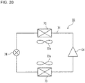
- a refrigeration cycle apparatus includes the air-sending device configured as described above, and a refrigerant circuit having a condenser and an evaporator.
- the air-sending device is configured to send air to at least one of the condenser and the evaporator.
- the virtual regional intermediate line which extends through the middle of the region between the regional inner edge and the regional outer edge, is located closer to the outer circumference than is the virtual blade intermediate line, which extends through the middle of the blade in the radial direction.
- the axial fan is designed such that the projection amount of its sectional portion increases with increasing distance from the front edge toward the rear edge. This allows the fluid on the pressure surface to easily flow along the sectional portion, which causes the fluid flow on the pressure surface to concentrate in the sectional portion.
- the above-mentioned configuration of the axial fan therefore makes it possible to reduce leakage of the fluid from the blade pressure surface at the outer circumferential end of the blade, and consequently reduce growth of a blade tip vortex.
- Fig. 1 is a schematic perspective view of an axial fan 100 according to Embodiment 1.
- a rotation direction DR shown by an arrow in Fig. 1 represents the direction of rotation of the axial fan 100.
- a circumferential direction CD shown by a double headed arrow in Fig. 1 represents the circumferential direction of the axial fan 100.
- the circumferential direction CD includes the rotation direction DR, and a direction opposite to the rotation direction DR.
- the far side of Fig. 1 corresponds to an upstream region upstream from the axial fan 100 in the direction of fluid flow
- the near side of Fig. 1 corresponds to a downstream region downstream from the axial fan 100 in the direction of fluid flow.
- the upstream region upstream from the axial fan 100 corresponds to a region where air is sucked into the axial fan 100
- the downstream region downstream from the axial fan 100 corresponds to a region where air is blown out from the axial fan 100.
- the axial fan 100 is a device for forming a flow of fluid.
- the axial fan 100 is used for, for example, an air-conditioning apparatus or a ventilator.
- the axial fan 100 forms a flow of fluid as the axial fan 100 rotates in the rotation direction DR about a rotation axis RA.
- An example of fluid is a gas such as air.
- the axial fan 100 includes a hub 10 disposed along the rotation axis RA, and multiple blades 20 connected to the hub 10.
- Examples of the axial fan 100 include commonly-called boss-less fans having multiple blades 20, with the leading and trailing edge portions of adjacent blades 20 being connected to define a continuous surface with no boss between the leading and trailing edge portions.
- the hub 10 is driven to rotate by a drive source such as a motor (not illustrated), and defines the rotation axis RA.
- the hub 10 rotates about the rotation axis RA.
- the rotation direction DR of the axial fan 100 is the counterclockwise direction shown by an arrow in Fig. 1 .
- the rotation direction DR of the axial fan 100 may not necessarily be the counterclockwise direction.
- the angle at which to mount the blades 20, or the orientation of the blades 20 may be changed such that the axial fan 100 rotates in the clockwise direction.
- the hub 10 is connected to the rotating shaft of a drive source such as a motor (not illustrated).
- the hub 10 may have a cylindrical shape, or may have a plate-like shape.
- the hub 10 is not limited to any particular shape as long as the hub 10 is connected to the rotating shaft of the drive source as mentioned above.
- the blades 20 extend radially outward from the hub 10.
- the multiple blades 20 are arranged in radial formation such that the blades 20 extend radially outward from the hub 10.
- the multiple blades 20 are spaced apart from each other in the circumferential direction CD.
- Embodiment 1 is directed to an exemplary case where there are three blades 20, the number of blades 20 is not limited to three.
- the blade 20 has a front edge 21, a rear edge 22, an outer circumferential edge 23, and an inner circumferential edge 24.
- the front edge 21 is located near the leading portion of the blade 20 in the rotation direction DR. That is, the front edge 21 is located forward of the rear edge 22 in the rotation direction DR.
- the front edge 21 is located upstream of the rear edge 22 in the direction of the fluid flow to be generated.
- the rear edge 22 is located near the trailing portion of the blade 20 in the rotation direction DR. That is, the rear edge 22 is located rearward of the front edge 21 in the rotation direction DR.
- the rear edge 22 is located downstream of the front edge 21 in the direction of the fluid flow to be generated.
- the axial fan 100 has the front edge 21 serving as a blade end oriented in the rotation direction DR of the axial fan 100, and the rear edge 22 serving as a blade end opposite to the front edge 21 in the rotation direction DR.
- the outer circumferential edge 23 extends from the front to the rear of the blade 20 in the rotation direction DR such that the outer circumferential edge 23 connects the outermost circumferential portion of the front edge 21 with the outermost circumferential portion of the rear edge 22.
- the outer circumferential edge 23 has an arcuate shape when viewed parallel to the rotation axis RA. However, the outer circumferential edge 23 may not necessarily have an arcuate shape when viewed parallel to the rotation axis RA.
- the outer circumferential edge 23 is located at an end near the outer circumference of the axial fan 100 (to be also referred to simply as "outer circumference" hereinafter) in the radial direction (Y-axis direction).
- the inner circumferential edge 24 extends from the front to the rear of the blade 20 in the rotation direction DR such that the inner circumferential edge 24 connects the innermost circumferential portion of the front edge 21 with the innermost circumferential portion of the rear edge 22.
- the inner circumferential edge 24 has an arcuate shape when viewed parallel to the rotation axis RA. However, the inner circumferential edge 24 may not necessarily have an arcuate shape when viewed parallel to the rotation axis RA.
- the inner circumferential edge 24 is located at an end near the inner circumference of the axial fan 100 (to be also referred to simply as "inner circumference" hereinafter) in the radial direction (Y-axis direction).
- the inner circumferential edge 24 of each blade 20 is connected to the hub 10, such as by being integrated with the hub 10.
- the blades 20 are inclined toward a plane perpendicular to the rotation axis RA. As the axial fan 100 rotates, the blade surface of each blade 20 pushes the fluid present between the blades 20 to thereby transport the fluid.
- a blade surface that pushes the fluid and undergoes an increase in pressure is defined as a pressure surface 25, and a blade surface that is on the back of the pressure surface 25 and undergoes a decrease in pressure is defined as a suction surface 26.
- the upstream surface of the blade 20 corresponds to the suction surface 26, and the downstream surface of the blade 20 corresponds to the pressure surface 25.
- a surface of the blade 20 depicted on the near side of Fig. 1 corresponds to the pressure surface 25, and a surface of the blade 20 depicted on the far side of Fig. 1 corresponds to the suction surface 26.
- Fig. 2 is a conceptual diagram representing a meridian plane of the axial fan 100 according to Embodiment 1.
- Fig. 2 illustrates the shape of the axial fan 100 when rotated and projected onto a meridian plane that covers the rotation axis RA and the blades 20.
- the shape of each blade 20 rotated and projected onto the meridian plane is represented by a blade projected portion 20p
- the shape of the hub 10 rotated and projected onto the meridian plane is represented by a hub projected portion 10p.
- a front-edge projection line 21p represents the shape of the front edge 21 rotated about the rotation axis RA and projected onto the meridian plane that covers the rotation axis RA.
- a rear-edge projection line 22p represents the shape of the rear edge 22 rotated about the rotation axis RA and projected onto the meridian plane that covers the rotation axis RA.
- An outer-edge projection line 23p represents the shape of the outer circumferential edge 23 rotated about the rotation axis RA and projected onto the meridian plane that covers the rotation axis RA.
- An inner-edge projection line 24p represents the shape of the inner circumferential edge 24 rotated about the rotation axis RA and projected onto the meridian plane that covers the rotation axis RA.
- a direction of flow AF shown by a vertically hatched arrow in Fig. 2 represents the direction of fluid flow into the axial fan 100.
- An axial direction AD shown by an open arrow in Fig. 2 represents the direction of the rotation axis RA.
- a viewpoint VP shown by a horizontally hatched arrow in Fig. 2 represents the direction of the line of sight taken parallel to the rotation axis RA.
- the Y-axis in Figs. 1 and 2 represents the radial direction from the rotation axis RA of the axial fan 100.
- Y2 represents a region of the axial fan 100 located closer to the inner circumference than is a region represented by Y1
- Y1 represents a region of the axial fan 100 located closer to the outer circumference that is the region represented by Y2.
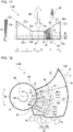
- Fig. 3 is a schematic front view of each blade 20 of the axial fan 100 according to Embodiment 1. To explain the configuration of each blade 20, Fig. 3 depicts only one of the multiple blades 20, and does not depict other blades 20. Airflows FL each shown by an open arrow in Fig. 3 each represent the flow of air downstream of the blade 20. The size of each open arrow showing the airflow FL conceptually represents airflow rate. The relative size of each open arrow showing the airflow FL represents relative airflow rate.
- the blade 20 has a blade length 27, which represents the distance between the inner circumferential edge 24 and the outer circumferential edge 23, and a virtual blade intermediate line 28, which represents the radially middle part of the blade length 27. That is, the virtual blade intermediate line 28 represents a position in the middle of the distance between the inner circumferential edge 24 and the outer circumferential edge 23.
- the blade length 27 is the same at any position in the circumferential direction CD of the axial fan 100. That is, the blade length 27 of the blade 20 is constant in the region between the front edge 21 and the rear edge 22, and the outer circumferential edge 23 of the blade 20 has the shape of a circular arc when viewed parallel to the axial direction AD aligned with the rotation axis RA.
- the blade length 27 of the blade 20 may not necessarily be constant in the region between the front edge 21 and the rear edge 22.
- the blade length 27 of the blade 20 may vary with the position in the circumferential direction CD of the axial fan 100. That is, the outer circumferential edge 23 of the blade 20 may not necessarily have the shape of a circular arc when viewed parallel to the axial direction AD aligned with the rotation axis RA.
- a position P1, a position P2, and a position P3 shown by dotted lines in Fig. 2 each represent the position of a section perpendicular to the rotation axis RA.
- the position P1, the position P2, and the position P3 are in this order from an upstream region toward a downstream region in the direction of fluid flow.
- Portions of the axial fan 100 located in the plane of the section shown at the position P1 are located at the same position in the axial direction AD aligned with the rotation axis RA.
- portions of the axial fan 100 located in the plane of the section shown at the position P2 are located at the same position in the axial direction AD aligned with the rotation axis RA.
- portions of the axial fan 100 located in the plane of the section shown at the position P3 are located at the same position in the axial direction AD aligned with the rotation axis RA.
- these portions of the axial fan 100 are located at different positions in the axial direction AD aligned with the rotation axis RA.
- the position P1, the position P2, and the position P3 are representative of their relative locations between the front edge 21 and the rear edge 22.
- the blade 20 has a flow control portion 30.
- the flow control portion 30 is a portion of the blade 20 that guides the flow of fluid on the pressure surface 25.
- the flow control portion 30 is located in at least part of the portion between the front edge 21 and the rear edge 22, and has a constant width in the radial direction perpendicular to the rotation axis RA.
- the flow control portion 30 is a region having an arcuate shape when viewed parallel to the rotation axis RA.
- the flow control portion 30 has a regional inner edge 31, and a regional outer edge 32.
- the regional inner edge 31 is located closer to the inner circumference than is the regional outer edge 32.
- the regional outer edge 32 is located closer to the outer circumference than is the regional inner edge 31.
- the regional outer edge 32 is located closer to the outer circumference of the axial fan 100 than is the virtual blade intermediate line 28 in the radial direction.
- the regional inner edge 31 is located closer to the outer circumference of the axial fan 100 than is the virtual blade intermediate line 28 in the radial direction. It is to be noted, however, that the regional inner edge 31 may be located closer to the inner circumference of the axial fan 100 than is the virtual blade intermediate line 28 in the radial direction.
- the regional inner edge 31 is formed in an arcuate shape, and located at a constant distance from the rotation axis RA in the radial direction of the axial fan 100.
- the regional outer edge 32 is formed in an arcuate shape, and located at a constant distance from the rotation axis RA in the radial direction of the axial fan 100.
- the flow control portion 30 is a region located between the regional inner edge 31 and the regional outer edge 32.
- the flow control portion 30 is located in at least part of the portion between the front edge 21 and the rear edge 22 in the circumferential direction CD of the axial fan 100. That is, the flow control portion 30 extends in the blade 20 in the radial direction of the axial fan 100 and also in the circumferential direction CD.
- the flow control portion 30 has a width in the radial direction that is constant at any position in the circumferential direction CD of the axial fan 100. That is, in the flow control portion 30, the distance between the regional inner edge 31 and the regional outer edge 32 in the radial direction is constant at any position in the circumferential direction CD of the axial fan 100. However, each of the regional inner edge 31 and the regional outer edge 32 may not necessarily be located at a constant distance from the rotation axis RA at any position in the radial direction of the axial fan 100. In this case, the axial fan 100 has a width in the radial direction that varies with the position in the circumferential direction CD of the axial fan 100.
- the flow control portion 30 is located relatively close to the outer circumference in the radial direction of the blade 20.
- the flow control portion 30 has a virtual regional intermediate line 33 that is located closer to the outer circumference than is the virtual blade intermediate line 28, which is located in the middle between the outer circumferential edge 23 and the inner circumferential edge 24. That is, the virtual regional intermediate line 33, which extends through the middle of the region between the regional inner edge 31 and the regional outer edge 32, is located closer to the outer circumference than is the virtual blade intermediate line 28, which extends through the middle of the blade 20 in the radial direction.
- the blade plate of the blade 20 is bent and cambered such that the section of the blade taken in the radial direction is convex in a direction opposite to the rotation direction DR of the axial fan 100.
- the blade plate is bent and cambered to be convex upstream in the direction of the fluid flow to be created by the blade 20. That is, in at least part of the flow control portion 30 in the circumferential direction CD of the axial fan 100, the pressure surface 25 of the blade 20 is concave.
- a sectional portion S shown by a dotted line in Fig. 3 represents a section of the blade 20 in the flow control portion 30.
- the sectional portion S represents a section of the flow control portion 30 perpendicular to the rotation axis RA.
- the flow control portion 30 has the sectional portion S, which is located between the regional inner edge 31 and the regional outer edge 32 and is a section perpendicular to the rotation axis RA.
- the sectional portion S is bent to have a concave part of the pressure surface 25, and a convex part of the suction surface 26.
- the sectional portion S is bent to be convex in a direction opposite to the rotation direction DR. Further, the sectional portion S is bent to be convex upstream in the direction of flow AF of the fluid.
- the sectional portion S is bent to have a concave part of the pressure surface 25, and a convex part of the suction surface 26.
- one end of the sectional portion S located near the inner circumference corresponds to the regional inner edge 31, and the other end of the sectional portion S located near the outer circumference corresponds to the regional outer edge 32.
- the suction surface 26 is not limited to a particular shape as long as the pressure surface 25 has a concave shape.
- the suction surface 26 is not limited to a particular shape as long as the pressure surface 25 is convex upstream in the direction of flow AF of the fluid to be created by the axial fan 100.
- a sectional portion S1 shown by a dotted line in Fig. 3 represents the sectional portion S of the blade 20 in the flow control portion 30 at the position P1 illustrated in Fig. 2 .
- a sectional portion S2 shown by a dotted line in Fig. 3 represents the sectional portion S of the blade 20 in the flow control portion 30 at the position P2 illustrated in Fig. 2 .
- a sectional portion S3 shown by a dotted line in Fig. 3 represents the sectional portion S of the blade 20 in the flow control portion 30 at the position P3 illustrated in Fig. 2 .
- the sectional portion S1 represents a section of the flow control portion 30 that is taken at the position P1 in the axial direction AD and is perpendicular to the rotation axis RA.
- the sectional portion S2 represents a section of the flow control portion 30 that is taken at the position P2 in the axial direction AD and is perpendicular to the rotation axis RA.
- the sectional portion S3 represents a section of the flow control portion 30 that is taken at the position P3 in the axial direction AD and is perpendicular to the rotation axis RA.
- one end of each of the sectional portions S1, S2, and S3 that is located near the inner circumference corresponds to the regional inner edge 31, and the other end of each of the sectional portions S1, S2, and S3 that is located near the outer circumference corresponds to the regional outer edge 32.
- the sectional portion S1, the sectional portion S2, and the sectional portion S3 of the flow control portion 30 are the sectional portions S that are positioned in this order from an upstream region toward a downstream region in the direction of fluid flow.
- the sectional portion S1, the sectional portion S2, and the sectional portion S3 of the flow control portion 30 are the sectional portions S that are positioned in this order in a direction from the front edge 21 to the rear edge 22.
- a straight line connecting the regional inner edge 31 and the regional outer edge 32 is defined as a sectional straight line W.
- the distance to a portion of the pressure surface 25 that is farthest in the normal direction from the sectional straight line W connecting the regional inner edge 31 and the regional outer edge 32 is defined as a projection amount L.
- the projection amount L represents the distance in the normal direction from the sectional straight line W to a deepest part 35 of the sectional portion S where the blade 20 is most convex.
- the deepest part 35 is the most concave part of the pressure surface 25 in the sectional portion S of the flow control portion 30.
- the deepest part 35 is a part where the sectional straight line W and the pressure surface 25 are farthest from each other in the sectional portion S of the flow control portion 30.
- the deepest part 35 is the most projecting part of the suction surface 26 in the sectional portion S of the flow control portion 30, and represents the vertex part of the convex shape defining the sectional portion S.
- a straight line connecting the regional inner edge 31 and the regional outer edge 32 is defined as a sectional straight line W1.
- the distance to a portion of the pressure surface 25 that is farthest in the normal direction from the sectional straight line W1 connecting the regional inner edge 31 and the regional outer edge 32 is defined as a projection amount L1.
- the projection amount L1 is the distance in the normal direction from the sectional straight line W1 to a deepest part 35a of the sectional portion S1 where the blade 20 is most convex.
- the deepest part 35a is the most concave part of the pressure surface 25 in the sectional portion S1 of the flow control portion 30.
- the deepest part 35a is a part where the sectional straight line W1 and the pressure surface 25 are farthest from each other in the sectional portion S1 of the flow control portion 30.
- the deepest part 35a is the most projecting part of the suction surface 26 in the sectional portion S1 of the flow control portion 30, and represents the vertex part of the convex shape defining the sectional portion S1.
- a straight line connecting the regional inner edge 31 and the regional outer edge 32 is defined as a sectional straight line W2.
- the distance to a portion of the pressure surface 25 that is farthest in the normal direction from the sectional straight line W2 connecting the regional inner edge 31 and the regional outer edge 32 is defined as a projection amount L2.
- the projection amount L2 is the distance in the normal direction from the sectional straight line W2 to a deepest part 35b of the sectional portion S2 where the blade 20 is most convex.
- the deepest part 35b is the most concave part of the pressure surface 25 in the sectional portion S2 of the flow control portion 30.
- the deepest part 35b is a part where the sectional straight line W2 and the pressure surface 25 are farthest from each other in the sectional portion S2 of the flow control portion 30.
- the deepest part 35b is the most projecting part of the suction surface 26 in the sectional portion S2 of the flow control portion 30, and represents the vertex part of the convex shape defining the sectional portion S2.
- a straight line connecting the regional inner edge 31 and the regional outer edge 32 is defined as a sectional straight line W3.
- the distance to a portion of the pressure surface 25 that is farthest in the normal direction from the sectional straight line W3 connecting the regional inner edge 31 and the regional outer edge 32 is defined as a projection amount L3.
- the projection amount L3 is the distance in the normal direction from the sectional straight line W3 to a deepest part 35c of the sectional portion S3 where the blade 20 is most convex.
- the deepest part 35c is the most concave part of the pressure surface 25 in the sectional portion S3 of the flow control portion 30.
- the deepest part 35c is a part where the sectional straight line W3 and the pressure surface 25 are farthest from each other in the sectional portion S3 of the flow control portion 30.
- the deepest part 35c is the most projecting part of the suction surface 26 in the sectional portion S3 of the flow control portion 30, and represents the vertex part of the convex shape defining the sectional portion S3.
- the flow control portion 30 of the blade 20 is formed between the front edge 21 and the rear edge 22, and bent such that the projection amount L increases with increasing distance from the front edge 21 toward the rear edge 22. That is, the flow control portion 30 of the blade 20 is formed between the front edge 21 and the rear edge 22 such that bending of the blade 20 that is directed upstream increases with increasing distance from the front edge 21 toward the rear edge 22. In other words, the flow control portion 30 of the blade 20 is formed between the front edge 21 and the rear edge 22 such that the concave part of the pressure surface 25 increases in depth with increasing distance from the front edge 21 toward the rear edge 22. Therefore, in the flow control portion 30 of the blade 20, the projection amount L2 is greater than the projection amount L1, and the projection amount L3 is greater than the projection amount L2.
- the flow control portion 30 of the blade 20 is formed between the front edge 21 and the rear edge 22 such that the projection amounts L1, L2, and L3 satisfy the following relationship: L1 ⁇ L2 ⁇ L3.
- the flow control portion 30 is formed in the same manner even when there are four or more sectional portions S. That is, in the circumferential direction CD, the projection amount L near the rear edge 22 is greater than the projection amount L near the front edge 21.
- the virtual regional intermediate line 33 which extends through the middle of the region between the regional inner edge 31 and the regional outer edge 32, is located closer to the outer circumference than is the virtual blade intermediate line 28, which extends through the middle of the blade 20 in the radial direction.
- the projection amount L of the sectional portion S increases with increasing distance from the front edge 21 toward the rear edge 22.
- the above-mentioned configuration of the axial fan 100 allows the fluid on the pressure surface 25 to easily flow along the sectional portion S. This causes a fluid flow MF on the pressure surface 25 to concentrate in the sectional portion S.
- the above-mentioned configuration of the axial fan 100 therefore helps to prevent the fluid from being guided excessively toward the outer circumference of the blade 20.
- a blade tip vortex refers to a vortex of air that is generated at the tip of the blade 20 because of a difference in pressure between the pressure surface 25 and the suction surface 26 of the blade 20.
- Generation of a blade tip vortex leads to unnecessary energy consumption. Accordingly, reducing generation of a blade tip vortex results in improved efficiency of the axial fan 100 and consequently reduced power consumption of the axial fan 100. Further, a blade tip vortex causes noise. Accordingly, reducing generation of a blade tip vortex helps to reduce noise associated with rotation of the blade 20.
- the virtual regional intermediate line 33 which extends through the middle of the region between the regional inner edge 31 and the regional outer edge 32, is located closer to the outer circumference than is the virtual blade intermediate line 28, which extends through the middle of the blade 20 between the inner circumferential edge 24 and the outer circumferential edge 23.
- the axial fan 100 has the sectional portion S that is located near the outer circumference of the blade 20 and bent to have a concave part of the pressure surface 25.
- the fluid is guided from a region located closer to the inner circumference than is the sectional portion S, toward the sectional portion S located in an outer circumferential region where work is efficiently done on the fluid.
- the airflow FL is greater in an outer circumferential region of the blade 20 where work is efficiently done on the fluid, than in an inner circumferential region of the blade 20. Accordingly, the axial fan 100 configured as described above efficiently does work on the fluid in comparison with axial fans in which a comparatively more fluid flows near the inner circumference of the blade 20. This leads to reduced power consumption of the axial fan 100.
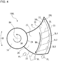
- Fig. 4 is a schematic front view of a blade 20L of an axial fan 100L according to a comparative example.
- a flow control portion 30L of the blade 20L has a sectional portion SL.
- the sectional portion SL represents a section of the flow control portion 30L perpendicular to the rotation axis RA.
- a sectional portion SL1 corresponds to the sectional portion SL at the position P1 illustrated in Fig. 2 .
- a sectional portion SL2 corresponds to the sectional portion SL at the position P2 illustrated in Fig. 2 .
- a sectional portion SL3 corresponds to the sectional portion SL at the position P3 illustrated in Fig. 2 .
- the sectional portion SL located near the outer circumference of the blade has a straight shape rather than a bent shape.
- the axial fan 100L does not draw, toward the inner circumference of the blade, a fluid flow directed toward the outer circumference of the blade. This may result in a leakage fluid flow at the outer circumferential end of the blade 20L.
- the fluid flow on the pressure surface 25 moves in the radial direction of the blade 20 with the radial component gradually increasing with increasing distance from an upstream region toward a downstream region in the direction of fluid flow.
- shaping the blade 20 to have the sectional portion S helps to prevent the fluid from being guided excessively toward the outer circumference of the blade 20 in the axial fan 100 according to Embodiment 1.
- the fluid flow concentrates in the sectional portion S of the blade 20. Therefore, the above-mentioned configuration makes it possible to reduce leakage of the fluid from the pressure surface 25 at the outer circumferential end of the blade 20, and consequently reduce growth of a blade tip vortex.
- the blade 20L of the axial fan 100L employs a configuration described below to reduce generation of a blade tip vortex. That is, the sectional portion SL is not formed in a convex shape, and is oriented to draw the flow of fluid toward the inner circumferential edge 24, with no changes in concavity and convexity from the front edge 21 to the rear edge 22.
- the above-mentioned configuration may make it possible for the axial fan 100L to draw the flow of fluid toward the inner circumferential edge 24 to thereby reduce the leakage of fluid at the outer circumferential end of the blade 20.
- the above-mentioned configuration of the axial fan 100L fails to increase the load on an outer circumferential region of the blade 20 where work is efficiently done on the fluid, and consequently fails to sufficiently reduce the power consumption of the axial fan 100.
- the axial fan 100L draws the fluid toward the inner circumferential edge 24. This causes a maximum air velocity region MA to develop on the pressure surface 25 where the fluid flow concentrates. As illustrated in Fig. 4 , the airflow FL concentrating in and then exiting from the maximum air velocity region MA is greater than the airflow FL near the inner circumferential edge 24 of the blade 20 and the airflow FL near the outer circumferential edge 23 of the blade 20. This results in increased energy loss of the axial fan 100L because of collision of the airflow with a structure such as a grill located downstream of the maximum air velocity region MA. This may lead to increased noise, and increased power consumption of the axial fan 100L.
- the axial fan 100 according to Embodiment 1 allows for increased air velocity in the sectional portion S located near the outer circumference in the radial direction. This helps to ensure that in the axial fan 100 according to Embodiment 1, the velocity distribution of the fluid blown by the axial fan 100 is made uniform in a region of the axial fan 100 located closer to the outer circumference than is the maximum air velocity region ML in the radial direction. Therefore, the axial fan 100 according to Embodiment 1 makes it possible to reduce energy loss resulting from the collision of the fluid with a structure such as a grill located downstream of the axial fan 100. The axial fan 100 according to Embodiment 1 also makes it possible to reduce noise resulting from the collision of the fluid with a structure such as a grill located downstream of the axial fan 100, and reduce the required power consumption of the axial fan 100.
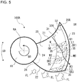
- Fig. 5 is a schematic front view of a blade 20R of an axial fan 100R according to another comparative example.
- a flow control portion 30R of the blade 20R has a sectional portion SR.
- the sectional portion SR represents a section of the flow control portion 30R perpendicular to the rotation axis RA.
- a sectional portion SR1 corresponds to the sectional portion SR at the position P1 illustrated in Fig. 2 .
- a sectional portion SR2 corresponds to the sectional portion SR at the position P2 illustrated in Fig. 2 .
- a sectional portion SR3 corresponds to the sectional portion SR at the position P3 illustrated in Fig. 2 .
- the sectional portion SR of the axial fan 100R according to the comparative example is bent such that the sectional portion SR is convex in a direction opposite to the rotation direction DR.
- the sectional portion SR is bent to have a concave part of the pressure surface 25, and a convex part of the suction surface 26.
- the axial fan 100R according to the comparative example has the sectional portion SR that is convex from a downstream region toward an upstream region in the direction of fluid flow. Because of the above-mentioned shape of the sectional portion SR, the fluid is guided from a region located closer to the inner circumference than is the sectional portion SR, toward the sectional portion S located in an outer circumferential region where work is efficiently done on the fluid. This makes it possible to increase the load in the outer circumferential region where work is efficiently done on the fluid.
- the axial fan 100R has the projection amount L that is constant from the front edge 21 to the rear edge 22. This results in a fluid flow MB being guided excessively toward the outer circumference.
- the airflow FL near the outer circumferential edge 23 of the blade 20 increases in comparison with the airflow FL near the inner circumferential edge 24 of the blade 20. Consequently, leakage of the fluid flow MB occurs at the outermost circumference of the blade 20 of the axial fan 100R.
- the resulting growth of a blade tip vortex may result in increased noise, or may result in increased power consumption of the axial fan 100R.
- the projection amount L of the sectional portion S increases with increasing distance from the front edge 21 toward the rear edge 22 in the direction of fluid flow. This allows the fluid on the pressure surface 25 to easily flow along the sectional portion S, which causes the fluid flow on the pressure surface 25 to concentrate in the sectional portion S.
- the above-mentioned configuration of the axial fan 100 according to Embodiment 1 helps to reduce leakage of the fluid from the pressure surface 25 at the outer circumferential end of the blade 20, and consequently reduce growth of a blade tip vortex.
- Fig. 6 is a schematic front view of a blade 20A of an axial fan 100A according to Embodiment 2. Reference is made below to Fig. 6 to describe the configuration of the blade 20A in detail. Portions or parts of the axial fan 100A identical in configuration to those of the axial fan 100 illustrated in Figs. 1 to 3 are denoted by the same reference signs and not described below in further detail. For the axial fan 100A according to Embodiment 2, the location of the deepest part 35 of a flow control portion 30A is specified.
- the deepest part 35 is the most concave part of the pressure surface 25 in the sectional portion S of the flow control portion 30. Further, the deepest part 35 is the most projecting part of the suction surface 26 in the sectional portion S of the flow control portion 30, and represents the vertex part of the convex shape defining the sectional portion S.
- the deepest part 35a corresponds to the deepest part 35 of the sectional portion S1 in the flow control portion 30A.
- the deepest part 35b corresponds to the deepest part 35 of the sectional portion S2 in the flow control portion 30A.
- the deepest part 35c corresponds to the deepest part 35 of the sectional portion S3 in the flow control portion 30A.
- the sectional portion S1, the sectional portion S2, and the sectional portion S3 of the flow control portion 30A are the sectional portions S that are positioned in this order in a direction from the front edge 21 to the rear edge 22.
- a distance R1 in Fig. 6 is the distance between the rotation axis RA and the deepest part 35a in the radial direction of the axial fan 100A.
- a distance R2 is the distance between the rotation axis RA and the deepest part 35b in the radial direction of the axial fan 100A.
- a distance R3 is the distance between the rotation axis RA and the deepest part 35c in the radial direction of the axial fan 100A.
- the distance R2 is greater than the distance R1
- the distance R3 is greater than the distance R2.
- the distances R1, R2, and R3 have the following relationship: R1 ⁇ R2 ⁇ R3.
- the deepest part 35 is located at a distance from the rotation axis RA in the radial direction that increases with increasing distance from the front edge 21 toward the rear edge 22 in the circumferential direction.
- the deepest part 35 is positioned further toward the outer circumferential edge 23 of the blade 20A from a location near the inner circumference in the radial direction.
- the deepest part 35 is positioned further toward the outer circumference in the radial direction with increasing distance from the front edge 21 toward the rear edge 22 in the circumferential direction.
- the fluid flow along the pressure surface 25 of the blade 20A caused by rotation of the axial fan 100 concentrates most at the deepest part 35 of the sectional portion S on the pressure surface 25 of the blade 20A. Accordingly, because of the above-mentioned configuration of the axial fan 100A in which the deepest part 35 is positioned further toward the outer circumference in the radial direction with increasing distance from the front edge 21 toward the rear edge 22, more fluid flow is guided toward an outer circumferential region where work is efficiently done on the fluid.
- the axial fan 100A directs more fluid toward the outer circumferential region of the blade 20A where work is efficiently done on the fluid. This makes it possible to reduce the required power consumption of the axial fan 100A. Further, the above-mentioned configuration allows for improved radial uniformity of the velocity distribution of the fluid blown by the axial fan 100A. This leads to reduced noise generation.
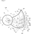
- Fig. 7 is a schematic front view of a blade 20B of an axial fan 100B according to Embodiment 3. Reference is made below to Fig. 7 to describe the configuration of the blade 20B in detail. Portions or parts of the axial fan 100B identical in configuration to those of the axial fans 100 and 100A illustrated in Figs. 1 to 6 are denoted by the same reference signs and not described below in further detail. For the axial fan 100B according to Embodiment 3, the orientation of the sectional portion S of a flow control portion 30B is specified.
- the sectional straight line W1 corresponds to the sectional straight line W connecting the regional inner edge 31 and the regional outer edge 32 in the sectional portion S1 of the flow control portion 30B at the position P1 illustrated in Fig. 2 .
- the intersection of the sectional straight line W1 and the regional inner edge 31 is defined as an inner-circumference-side end W1a
- the intersection of the sectional straight line W1 and the regional outer edge 32 is defined as an outer-circumference-side end W1b.
- the inner-circumference-side end W1a is an end of the sectional straight line W1 located near the inner circumference in the radial direction.
- the outer-circumference-side end W1b is an end of the sectional straight line W1 located near the outer circumference in the radial direction. In the circumferential direction, the outer-circumference-side end W1b is located closer to the front edge 21 than is the inner-circumference-side end W1a, and the inner-circumference-side end W1a is located closer to the rear edge 22 than is the outer-circumference-side end W1b. That is, in the flow control portion 30B, the outer-circumference-side end W1b is located closer to the leading portion of the axial fan 100B in the rotation direction DR than is the inner-circumference-side end W1a.
- a straight line passing the rotation axis RA and the inner-circumference-side end W1a is defined as a straight line M1a
- a straight line passing the rotation axis RA and the outer-circumference-side end W1b is defined as a straight line M1b.
- the angle between the straight line M1a and the straight line M1b in the circumferential direction is defined as an angle ⁇ 1.
- the angle ⁇ 1 is an angle defined between the two straight lines, that is, the straight line M1a connecting the rotation axis RA, which is at the center of the axial fan 100B, with the inner-circumference-side end W1a of the sectional portion S1 of the flow control portion 30B, and the straight line M1b connecting the rotation axis RA with the outer-circumference-side end W1b of the sectional portion S1 of the flow control portion 30B.
- the sectional straight line W2 corresponds to the sectional straight line W connecting the regional inner edge 31 and the regional outer edge 32 in the sectional portion S2 of the flow control portion 30B at the position P2 illustrated in Fig. 2 .
- the intersection of the sectional straight line W2 and the regional inner edge 31 is defined as an inner-circumference-side end W2a
- the intersection of the sectional straight line W2 and the regional outer edge 32 is defined as an outer-circumference-side end W2b.
- the inner-circumference-side end W2a is an end of the sectional straight line W2 located near the inner circumference in the radial direction.
- the outer-circumference-side end W2b is an end of the sectional straight line W2 located near the outer circumference in the radial direction. In the circumferential direction, the outer-circumference-side end W2b is located closer to the front edge 21 than is the inner-circumference-side end W2a, and the inner-circumference-side end W2a is located closer to the rear edge 22 than is the outer-circumference-side end W2b. That is, in the flow control portion 30B, the outer-circumference-side end W2b is located closer to the leading portion of the axial fan 100B in the rotation direction DR than is the inner-circumference-side end W2a.
- a straight line passing the rotation axis RA and the inner-circumference-side end W2a is defined as a straight line M2a
- a straight line passing the rotation axis RA and the outer-circumference-side end W2b is defined as a straight line M2b.
- the angle between the straight line M2a and the straight line M2b in the circumferential direction is defined as an angle ⁇ 2.
- the angle ⁇ 2 is an angle defined between the two straight lines, that is, the straight line M2a connecting the rotation axis RA, which is at the center of the axial fan 100B, with the inner-circumference-side end W2a of the sectional portion S2 of the flow control portion 30B, and the straight line M2b connecting the rotation axis RA with the outer-circumference-side end W2b of the sectional portion S2 of the flow control portion 30B.
- the sectional straight line W3 corresponds to the sectional straight line W connecting the regional inner edge 31 and the regional outer edge 32 in the sectional portion S3 of the flow control portion 30B at the position P3 illustrated in Fig. 2 .
- the intersection of the sectional straight line W3 and the regional inner edge 31 is defined as an inner-circumference-side end W3a
- the intersection of the sectional straight line W3 and the regional outer edge 32 is defined as an outer-circumference-side end W3b.
- the inner-circumference-side end W3a is an end of the sectional straight line W3 located near the inner circumference in the radial direction.
- the outer-circumference-side end W3b is an end of the sectional straight line W3 located near the outer circumference in the radial direction. In the circumferential direction, the outer-circumference-side end W3b is located closer to the front edge 21 than is the inner-circumference-side end W3a, and the inner-circumference-side end W3a is located closer to the rear edge 22 than is the outer-circumference-side end W3b. That is, in the flow control portion 30B, the outer-circumference-side end W3b is located closer to the leading portion of the axial fan 100B in the rotation direction DR than is the inner-circumference-side end W3a.
- a straight line passing the rotation axis RA and the inner-circumference-side end W3a is defined as a straight line M3a
- a straight line passing the rotation axis RA and the outer-circumference-side end W3b is defined as a straight line M3b.
- the angle between the straight line M3a and the straight line M3b in the circumferential direction is defined as an angle ⁇ 3.
- the angle ⁇ 3 is an angle defined between the two straight lines, that is, the straight line M3a connecting the rotation axis RA, which is at the center of the axial fan 100B, with the inner-circumference-side end W3a of the sectional portion S3 of the flow control portion 30B, and the straight line M3b connecting the rotation axis RA with the outer-circumference-side end W3b of the sectional portion S3 of the flow control portion 30B.
- the inner-circumference-side end W1a, the inner-circumference-side end W2a, and the inner-circumference-side end W3a each correspond to a first inner-circumference-side end
- the outer-circumference-side end W1b, the outer-circumference-side end W2b, and the outer-circumference-side end W3b each correspond to a first outer-circumference-side end
- the straight line M1a, the straight line M2a, and the straight line M3a each correspond to a first straight line
- the straight line M1b, the straight line M2b, and the straight line M3b each correspond to a second straight line.
- the angle between the first straight line and the second straight line is the angle ⁇ .
- the angle ⁇ 2 is greater than the angle ⁇ 1, and the angle ⁇ 3 is greater than the angle ⁇ 2.
- the flow control portion 30B of the blade 20B is formed between the front edge 21 and the rear edge 22 such that the angles ⁇ 1, ⁇ 2, and ⁇ 3 satisfy the following relationship: ⁇ 1 ⁇ ⁇ 2 ⁇ ⁇ 3.
- the angle ⁇ which is defined between the first straight line connecting the rotation axis RA with the inner-circumference-side end of the flow control portion 30B, and the second straight line connecting the rotation axis RA with the outer-circumference-side end of the flow control portion 30B, is greater near the rear edge 22 than near the front edge 21.
- the flow control portion 30B is formed in the same manner even when there are four or more sectional portions S. That is, in the flow control portion 30B, the angle ⁇ , which is defined between the first straight line connecting the rotation axis RA with the inner-circumference-side end of the flow control portion 30B, and the second straight line connecting the rotation axis RA with the outer-circumference-side end of the flow control portion 30B, is greater near the rear edge 22 than near the front edge 21.
- the angle ⁇ which is defined between the first straight line connecting the rotation axis RA with the inner-circumference-side end of the flow control portion 30B, and the second straight line connecting the rotation axis RA with the outer-circumference-side end of the flow control portion 30B, is greater near the rear edge 22 than near the front edge 21. Because of the above-mentioned configuration of the axial fan 100B, a plane bounded by the sectional portion S and the sectional straight line W is oriented increasingly toward the inner circumference with increasing distance from the front edge 21 toward the rear edge 22.
- the above-mentioned configuration of the axial fan 100B makes it possible to reduce the radial flow of the fluid toward a region located closer to the outer circumference than is the flow control portion 30B. As a result, the fluid flow directed toward the outer circumferential region of the blade 20B is allowed to concentrate in the flow control portion 30B. Further, the above-mentioned configuration of the axial fan 100B makes it possible to reduce leakage of the fluid from the pressure surface 25 at an end near the outer circumference of the blade 20B. This helps to reduce growth of a blade tip vortex. Therefore, the efficiency of the axial fan 100B is improved, and the required power consumption of the axial fan 100B is reduced.
- Fig. 8 is a schematic front view of a blade 20C of an axial fan 100C according to Embodiment 4. Reference is made below to Fig. 8 to describe the configuration of the blade 20C in detail. Portions or parts of the axial fan 100C identical in configuration to those of the axial fans 100 to 100B illustrated in Figs. 1 to 7 are denoted by the same reference signs and not described below in further detail.
- the orientation of the sectional portion S of a flow control portion 30C is specified, which differs from the orientation of the sectional portion S of the flow control portion 30C in the axial fan 100B according to Embodiment 3.
- the angle ⁇ 2 is less than the angle ⁇ 1, and the angle ⁇ 3 is less than the angle ⁇ 2.
- the flow control portion 30C of the blade 20C is formed between the front edge 21 and the rear edge 22 such that the angles ⁇ 1, ⁇ 2, and ⁇ 3 satisfy the following relationship: ⁇ 3 ⁇ ⁇ 2 ⁇ ⁇ 1.
- the angle ⁇ which is defined between the first straight line connecting the rotation axis RA with the inner-circumference-side end of the flow control portion 30C, and the second straight line connecting the rotation axis RA with the outer-circumference-side end of the flow control portion 30C, is less near the rear edge 22 than near the front edge 21.
- the flow control portion 30C is formed in the same manner even when there are four or more sectional portions S. That is, in the flow control portion 30C, the angle ⁇ , which is defined between the first straight line connecting the rotation axis RA with the inner-circumference-side end of the flow control portion 30C, and the second straight line connecting the rotation axis RA with the outer-circumference-side end of the flow control portion 30C, is less near the rear edge 22 than near the front edge 21.
- the angle ⁇ which is defined between the first straight line connecting the rotation axis RA with the inner-circumference-side end of the flow control portion 30C, and the second straight line connecting the rotation axis RA with the outer-circumference-side end of the flow control portion 30C, is less near the rear edge 22 than near the front edge 21. Because of the above-mentioned configuration of the axial fan 100C, a plane bounded by the sectional portion S and the sectional straight line W becomes increasingly oriented in the rotation direction DR with increasing distance from the front edge 21 toward the rear edge 22.
- the above-mentioned configuration of the axial fan 100C makes it possible to reduce the radial component of the fluid flow in the flow control portion 30C that is directed toward the inner circumference or the outer circumference. This allows the fluid flow to concentrate in the sectional portion S of the flow control portion 30C. Further, the above-mentioned configuration of the axial fan 100C makes it possible to reduce leakage of the fluid from the pressure surface 25 at an end near the outer circumference of the blade 20C. This helps to reduce growth of a blade tip vortex. Therefore, the efficiency of the axial fan 100C is improved, and the required power consumption of the axial fan 100C is reduced. Further, the above-mentioned configuration allows for improved radial uniformity of the velocity distribution of the fluid blown by the axial fan 100C. This leads to reduced noise generation.
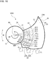
- Fig. 9 is a schematic front view of a blade 20D of an axial fan 100D according to Embodiment 5. Reference is made below to Fig. 9 to describe the configuration of the blade 20D in detail. Portions or parts of the axial fan 100D identical in configuration to those of the axial fans 100 to 100C illustrated in Figs. 1 to 8 are denoted by the same reference signs and not described below in further detail. For the axial fan 100D according to Embodiment 5, the configuration of the rear edge 22 of the blade 20D is specified.
- the rear edge 22 has a projecting part 22a, which is located in a portion of the blade 20 near the rotation axis RA, and an outer-circumference-side rear edge 22b, which is located closer to the outer circumferential edge 23 of the blade 20 than is the projecting part 22a.
- the projecting part 22a is located near the inner circumference of the blade 20 in the radial direction.
- the rear edge is extended in the circumferential direction. That is, the projecting part 22a extends to project toward the trailing portion of the blade 20D in the rotation direction DR in comparison with the outer-circumference-side rear edge 22b.
- the projecting part 22a is in the form of a flat plate, and has a substantially triangular shape when viewed parallel to the direction of the rotation axis RA.
- the projecting part 22a is tapered in the direction in which the projecting part 22a projects.
- the projecting part 22a may not necessarily have a substantially triangular shape.
- the projecting part 22a may have another shape when viewed parallel to the direction of the rotation axis RA, such as a substantially trapezoidal shape and a shape made up of multiple substantially triangular shapes.
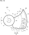
- Fig. 10 is another schematic front view of the blade 20D of the axial fan 100D according to Embodiment 5.
- the axial fan 100D may have a flow control portion 30D located near the outer circumference of the blade 20D in the radial direction.
- the flow control portion 30D is formed by one of the above-mentioned flow control portions 30, 30A, 30B, and 30C.
- the rear edge 22 has the projecting part 22a, which is located in a portion of the blade 20 near the rotation axis RA, and the outer-circumference-side rear edge 22b, which is located closer to the outer circumferential edge 23 of the blade 20 than is the projecting part 22a.
- the projecting part 22a extends to project toward the trailing portion of the blade 20D in the rotation direction DR in comparison with the outer-circumference-side rear edge 22b.
- the presence of the projecting part 22a which defines a portion of the rear edge 22 near the inner circumference, allows for increased air velocity in a region that is located closer to the inner circumference than is the maximum air velocity region in the radial direction.
- Fig. 11 is a conceptual diagram representing a meridian plane of an axial fan 100E according to Embodiment 6.
- Fig. 12 is a schematic front view of a blade 20E of the axial fan 100E according to Embodiment 6.
- Fig. 11 illustrates the shape of the axial fan 100E when rotated and projected onto a meridian plane that covers the rotation axis RA and the blade 20E.
- the shape of the blade 20E rotated and projected onto the meridian plane is represented by a blade projected portion 20q
- the shape of the hub 10 rotated and projected onto the meridian plane is represented by the hub projected portion 10p.
- the hub projected portion 10p Reference is made below to Figs.
- a position Q1, a position Q2, and a position Q3 shown by dotted lines in Fig. 12 each represent the position of a section perpendicular to the rotation axis RA.
- the position Q1, the position Q2, and the position Q3 are in this order from an upstream region toward a downstream region in the direction of fluid flow.
- Portions of the axial fan 100E located in the plane of the section shown at the position Q1 represent portions of the axial fan 100E that are located at the same position in the axial direction AD aligned with the rotation axis RA.
- portions of the axial fan 100E located in the plane of the section shown at the position Q2 are located at the same position in the axial direction AD aligned with the rotation axis RA.
- portions of the axial fan 100E located in the plane of the section shown at the position Q3 are located at the same position in the axial direction AD aligned with the rotation axis RA.
- each portion of the axial fan 100E located in the plane of the section shown at the position Q1 each portion of the axial fan 100E located in the plane of the section shown at the position Q2, and each portion of the axial fan 100E located in the plane of the section shown at the position Q3, these portions of the axial fan 100E are located at different positions in the axial direction AD aligned with the rotation axis RA.
- the position Q1, the position Q2, and the position Q3 are representative of their relative locations between the front edge 21 and the rear edge 22.
- the blade 20E has an inner-circumference-side flow control portion 40.
- the inner-circumference-side flow control portion 40 is located near the inner circumference of the blade 20E to guide the flow of fluid on the pressure surface 25. In the circumferential direction CD, the inner-circumference-side flow control portion 40 is located at least between a midsection 29, which is located midway between the front edge 21 and the rear edge 22, and the rear edge 22.
- the inner-circumference-side flow control portion 40 is formed with a constant width such that in the radial direction, the inner-circumference-side flow control portion 40 is positioned to at least partially overlap a region where the projecting part 22a is provided.
- the inner-circumference-side flow control portion 40 is a region having an arcuate shape when viewed parallel to the rotation axis RA.
- the inner-circumference-side flow control portion 40 has an inner-circumference-side regional inner edge 41, and an inner-circumference-side regional outer edge 42.
- the inner-circumference-side regional inner edge 41 is located closer to the inner circumference than is the inner-circumference-side regional outer edge 42.
- the inner-circumference-side regional outer edge 42 is located closer to the outer circumference than is the inner-circumference-side regional inner edge 41.
- the inner-circumference-side regional inner edge 41 is located closer to the inner circumference of the axial fan 100E than is the virtual blade intermediate line 28 in the radial direction.
- the inner-circumference-side regional outer edge 42 is located closer to the inner circumference of the axial fan 100E than is the virtual blade intermediate line 28 in the radial direction. It is to be noted, however, that the inner-circumference-side regional outer edge 42 may be located closer to the outer circumference of the axial fan 100E than is the virtual blade intermediate line 28 in the radial direction.
- the inner-circumference-side regional inner edge 41 is formed in an arcuate shape, and located at a constant distance from the rotation axis RA in the radial direction of the axial fan 100E.
- the inner-circumference-side regional outer edge 42 is formed in an arcuate shape, and located at a constant distance from the rotation axis RA in the radial direction of the axial fan 100E.
- the inner-circumference-side flow control portion 40 is a region located between the inner-circumference-side regional inner edge 41 and the inner-circumference-side regional outer edge 42.
- the inner-circumference-side flow control portion 40 is located in at least part of the portion between the front edge 21 and the rear edge 22 in the circumferential direction CD of the axial fan 100E. That is, the inner-circumference-side flow control portion 40 extends in the blade 20E in the radial direction of the axial fan 100E and also in the circumferential direction CD.
- the inner-circumference-side flow control portion 40 has a width in the radial direction that is constant at any position in the circumferential direction CD of the axial fan 100E. That is, in the inner-circumference-side flow control portion 40, the distance between the inner-circumference-side regional inner edge 41 and the inner-circumference-side regional outer edge 42 in the radial direction is constant at any position in the circumferential direction CD of the axial fan 100E.
- each of the inner-circumference-side regional inner edge 41 and the inner-circumference-side regional outer edge 42 may not necessarily be located at the constant distance from the rotation axis RA at any position in the circumferential direction CD of the axial fan 100E.
- the axial fan 100E has a width in the radial direction that varies with the position in the circumferential direction CD of the axial fan 100E.
- the inner-circumference-side flow control portion 40 is located relatively close to the inner circumference in the radial direction of the blade 20E.
- the inner-circumference-side flow control portion 40 has an inner-circumference-side virtual regional intermediate line 43 that is located closer to the inner circumference than is the virtual blade intermediate line 28 located between the outer circumferential edge 23 and the inner circumferential edge 24, that is, the virtual blade intermediate line 28 extending through the middle of the blade 20E in the radial direction.
- the inner-circumference-side flow control portion 40 is provided in a region that is equal in size in the radial direction to the region where the projecting part 22a of the rear edge 22 is provided.
- the inner-circumference-side flow control portion 40 may not necessarily be formed in a region that is equal in size in the radial direction to the region where the projecting part 22a of the rear edge 22 is provided.
- the inner-circumference-side flow control portion 40 may be provided in a region that is smaller in the radial direction than the region where the projecting part 22a of the rear edge 22 is provided, or may be formed in a region that is larger in the radial direction than the region where the projecting part 22a of the rear edge 22 is provided.
- at least part of the inner-circumference-side flow control portion 40 only has to be located in a region where the projecting part 22a of the rear edge 22 is provided.
- the blade plate of the blade 20E in at least part of a portion of the blade 20E between the front edge 21 and the rear edge 22 in the circumferential direction CD, is bent and cambered such that the section of the blade taken in the radial direction is convex in a direction opposite to the rotation direction DR of the axial fan 100E.
- the blade plate in at least part of the portion of the blade 20E between the front edge 21 and the rear edge 22 in the circumferential direction CD, the blade plate is bent and cambered to be convex upstream in the direction of fluid flow.
- the pressure surface 25 of the blade 20E is concave
- the suction surface 26 of the blade 20E in the corresponding part of the axial fan 100E is convex.
- An inner-circumference-side sectional portion SI shown by a dotted line in Fig. 12 represents a section of the blade 20E in the inner-circumference-side flow control portion 40.
- the inner-circumference-side sectional portion SI is located between the inner-circumference-side regional inner edge 41 and the inner-circumference-side regional outer edge 42, and is a section perpendicular to the rotation axis RA.
- the inner-circumference-side sectional portion SI is bent to have a concave part of the pressure surface 25, and a convex part of the suction surface 26.
- the inner-circumference-side sectional portion SI represents a section of the inner-circumference-side flow control portion 40 perpendicular to the rotation axis RA.
- the inner-circumference-side sectional portion SI is bent to be convex in a direction opposite to the rotation direction DR. Further, the inner-circumference-side sectional portion SI is bent to be convex upstream in the direction of flow AF of the fluid. The inner-circumference-side sectional portion SI is bent to have a concave part of the pressure surface 25, and a convex part of the suction surface 26.
- one end of the inner-circumference-side sectional portion SI located near the inner circumference corresponds to the inner-circumference-side regional inner edge 41
- the other end of the sectional portion S located near the outer circumference corresponds to the inner-circumference-side regional outer edge 42.
- An inner-circumference-side sectional portion SI1 shown by a dotted line in Fig. 12 represents the inner-circumference-side sectional portion SI of the blade 20E in the inner-circumference-side flow control portion 40 at the position Q1 illustrated in Fig. 11 .
- An inner-circumference-side sectional portion SI2 shown by a dotted line in Fig. 12 represents the inner-circumference-side sectional portion SI of the blade 20E in the inner-circumference-side flow control portion 40 at the position Q2 illustrated in Fig. 11 .
- the inner-circumference-side sectional portion SI1 represents a section of the inner-circumference-side flow control portion 40 taken at the position Q1 in the axial direction AD and perpendicular to the rotation axis RA.
- the inner-circumference-side sectional portion SI2 represents a section of the inner-circumference-side flow control portion 40 taken at the position Q2 in the axial direction AD and perpendicular to the rotation axis RA.
- the inner-circumference-side sectional portion SI3 represents a section of the inner-circumference-side flow control portion 40 taken at the position Q3 in the axial direction AD and perpendicular to the rotation axis RA.
- one end of each of the inner-circumference-side sectional portions SI1, S12, and SI3 that is located near the inner circumference corresponds to the inner-circumference-side regional inner edge 41.
- the other end of each of the inner-circumference-side sectional portions SI1, SI2, and SI3 that is located near the outer circumference corresponds to the inner-circumference-side regional outer edge 42.
- the inner-circumference-side sectional portion S11, the inner-circumference-side sectional portion SI2, and the inner-circumference-side sectional portion SI3 are the inner-circumference-side sectional portions SI that are positioned in this order from an upstream region toward a downstream region in the direction of fluid flow.
- the inner-circumference-side sectional portion S11, the inner-circumference-side sectional portion S12, and the inner-circumference-side sectional portion SI3 are the inner-circumference-side sectional portions SI that are positioned in this order in a direction from the front edge 21 toward the rear edge 22.
- each inner-circumference-side sectional portion SI of the inner-circumference-side flow control portion 40 located at the same position in the axial direction AD of the axial fan 100E a straight line connecting the inner-circumference-side regional inner edge 41 and the inner-circumference-side regional outer edge 42 is defined as an inner-circumference-side straight line WI.
- the distance to a portion of the pressure surface 25 that is farthest in the normal direction from the inner-circumference-side straight line WI connecting the inner-circumference-side regional inner edge 41 and the inner-circumference-side regional outer edge 42 is defined as a projection amount LI.
- the inner-circumference-side projection amount LI represents the distance in the normal direction from the inner-circumference-side straight line WI to an inner-circumference-side deepest part 45 of the inner-circumference-side sectional portion SI where the blade 20E is most convex.
- the inner-circumference-side deepest part 45 is the most concave part of the pressure surface 25 in the inner-circumference-side sectional portion SI of the inner-circumference-side flow control portion 40. That is, the inner-circumference-side deepest part 45 is a part where the inner-circumference-side straight line WI and the pressure surface 25 are farthest from each other in the inner-circumference-side sectional portion SI of the inner-circumference-side flow control portion 40.
- the inner-circumference-side deepest part 45 is the most projecting part of the suction surface 26 in the inner-circumference-side sectional portion SI of the inner-circumference-side flow control portion 40, and represents the vertex part of the convex shape defining the inner-circumference-side sectional portion SI.
- a straight line connecting the inner-circumference-side regional inner edge 41 and the inner-circumference-side regional outer edge 42 is defined as an inner-circumference-side straight line WI1.
- the distance to a portion of the pressure surface 25 that is farthest in the normal direction from the inner-circumference-side straight line WI1 connecting the inner-circumference-side regional inner edge 41 and the inner-circumference-side regional outer edge 42 is defined as an inner-circumference-side projection amount LI1.
- the inner-circumference-side projection amount LI1 represents the distance in the normal direction from the inner-circumference-side straight line WI1 to an inner-circumference-side deepest part 45a of the inner-circumference-side sectional portion SI1 where the blade 20E is most convex.
- the inner-circumference-side deepest part 45a is the most concave part of the pressure surface 25 in the inner-circumference-side sectional portion SI1 of the inner-circumference-side flow control portion 40.
- the inner-circumference-side deepest part 45a is a part where the inner-circumference-side straight line WI1 and the pressure surface 25 are farthest from each other in the inner-circumference-side sectional portion SI1 of the inner-circumference-side flow control portion 40.
- the inner-circumference-side deepest part 45a is the most projecting part of the suction surface 26 in the inner-circumference-side sectional portion SI1 of the inner-circumference-side flow control portion 40, and represents the vertex part of the convex shape defining the inner-circumference-side sectional portion S11.
- a straight line connecting the inner-circumference-side regional inner edge 41 and the inner-circumference-side regional outer edge 42 is defined as an inner-circumference-side straight line WI2.
- the distance to a portion of the pressure surface 25 that is farthest in the normal direction from the inner-circumference-side straight line WI2 connecting the inner-circumference-side regional inner edge 41 and the inner-circumference-side regional outer edge 42 is defined as an inner-circumference-side projection amount LI2.
- the inner-circumference-side projection amount LI2 represents the distance in the normal direction from the inner-circumference-side straight line WI2 to an inner-circumference-side deepest part 45b of the inner-circumference-side sectional portion SI2 where the blade 20E is most convex.
- the inner-circumference-side deepest part 45b is the most concave part of the pressure surface 25 in the inner-circumference-side sectional portion SI2 of the inner-circumference-side flow control portion 40.
- the inner-circumference-side deepest part 45b is a part where the inner-circumference-side straight line WI2 and the pressure surface 25 are farthest from each other in the inner-circumference-side sectional portion SI2 of the inner-circumference-side flow control portion 40.
- the inner-circumference-side deepest part 45b is the most projecting part of the suction surface 26 in the inner-circumference-side sectional portion SI2 of the inner-circumference-side flow control portion 40, and represents the vertex part of the convex shape defining the inner-circumference-side sectional portion SI2.
- a straight line connecting the inner-circumference-side regional inner edge 41 and the inner-circumference-side regional outer edge 42 is defined as an inner-circumference-side straight line WI3.
- the distance to a portion of the pressure surface 25 that is farthest in the normal direction from the inner-circumference-side straight line WI3 connecting the inner-circumference-side regional inner edge 41 and the inner-circumference-side regional outer edge 42 is defined as an inner-circumference-side projection amount LI3.
- the inner-circumference-side projection amount LI3 represents the distance in the normal direction from the inner-circumference-side straight line WI3 to an inner-circumference-side deepest part 45c of the inner-circumference-side sectional portion SI3 where the blade 20E is most convex.
- the inner-circumference-side deepest part 45c is the most concave part of the pressure surface 25 in the inner-circumference-side sectional portion SI3 of the inner-circumference-side flow control portion 40.
- the inner-circumference-side deepest part 45c is a part where the inner-circumference-side straight line WI3 and the pressure surface 25 are farthest from each other in the inner-circumference-side sectional portion SI3 of the inner-circumference-side flow control portion 40.
- the inner-circumference-side deepest part 45c is the most projecting part of the suction surface 26 in the inner-circumference-side sectional portion SI3 of the inner-circumference-side flow control portion 40, and represents the vertex part of the convex shape defining the inner-circumference-side sectional portion SI3.
- the inner-circumference-side flow control portion 40 of the blade 20E is formed between the front edge 21 and the rear edge 22 such that the inner-circumference-side projection amount LI decreases with increasing distance from the front edge 21 toward the rear edge 22. That is, the inner-circumference-side flow control portion 40 of the blade 20E is formed between the front edge 21 and the rear edge 22 such that bending of the blade 20E that is directed upstream decreases with increasing distance from the front edge 21 toward the rear edge 22. In other words, in the inner-circumference-side flow control portion 40 of the blade 20E, the concave part of the pressure surface 25 decreases in depth with increasing distance from the front edge 21 toward the rear edge 22.
- the region of decreasing inner-circumference-side projection amount LI is located at least in a region of the blade 20E between the midsection 29 and the rear edge 22.
- the midsection 29 of the blade 20E is located midway between the front edge 21 and the rear edge 22 in the direction of the rotation axis RA.
- the inner-circumference-side projection amount LI2 is less than the inner-circumference-side projection amount LI1
- the inner-circumference-side projection amount LI3 is less than the inner-circumference-side projection amount LI2.
- the inner-circumference-side flow control portion 40 of the blade 20E is formed between the front edge 21 and the rear edge 22 such that the inner-circumference-side projection amounts LI1, LI2, and LI3 satisfy the following relationship: LI3 ⁇ LI2 ⁇ LI1.
- the inner-circumference-side flow control portion 40 is formed in the same manner even when there are four or more inner-circumference-side sectional portions SI. That is, in the circumferential direction CD, the inner-circumference-side projection amount LI near the rear edge 22 is less than the inner-circumference-side projection amount LI near the front edge 21.
- the inner-circumference-side flow control portion 40 of the blade 20E may not necessarily be formed between the front edge 21 and the rear edge 22 such that inner-circumference-side projection amount LI decreases with increasing distance from the front edge 21 toward the rear edge 22.
- the inner-circumference-side flow control portion 40 of the blade 20E only has to be formed between the front edge 21 and the rear edge 22 such that the inner-circumference-side projection amount LI does not increase with increasing distance from the front edge 21 toward the rear edge 22. Accordingly, the inner-circumference-side flow control portion 40 may have a region where the inner-circumference-side projection amount LI remains constant with increasing distance from the front edge 21 toward the rear edge 22.
- Such a region of constant inner-circumference-side projection amount LI may be present in either a portion or entirety of a region of the blade 20E from the front edge 21 to the rear edge 22.
- the region of constant inner-circumference-side projection amount LI is located at least in a region of the blade 20E between the midsection 29 and the rear edge 22.
- the blade 20E has, between the front edge 21 and the rear edge, at least a region of constant inner-circumference-side projection amount LI in a portion of the blade 20E from the midsection 29 to the rear edge 22, or at least a region of decreasing inner-circumference-side projection amount LI in a portion of the blade 20E with increasing distance from the midsection 29 toward the rear edge 22. That is, the blade 20E has a region where the inner-circumference-side projection amount LI does not change with increasing distance from the front edge 21 toward the rear edge 22, or a region where the inner-circumference-side projection amount LI decreases with increasing distance from the front edge 21 toward the rear edge 22.
- Fig. 13 is a schematic front view of a blade 20F of an axial fan 100F according to a modification of Embodiment 6.
- the axial fan 100F has the inner-circumference-side flow control portion 40 located near the inner circumference of the blade 20F, and the flow control portion 30 located near the outer circumference of the blade 20F.
- the flow control portion 30 may be one of the flow control portions 30A to 30D.
- the position Q1, the position Q2, and the position Q3 in Fig. 2 are representative of their relative locations between the front edge 21 and the rear edge 22.
- the position Q1, the position Q2, and the position Q3 of the inner-circumference-side sectional portion SI of the inner-circumference-side flow control portion 40 which are illustrated in Fig. 13 , may be respectively the same as or different from the position P1, the position P2, and the position P3 of the sectional portion S of the flow control portion 30.
- the blade 20E has a region where the inner-circumference-side projection amount LI does not change with increasing distance from the front edge 21 toward the rear edge 22, or a region where the inner-circumference-side projection amount LI decreases with increasing distance from the front edge 21 toward the rear edge 22.
- the above-mentioned configuration of the axial fan 100E helps to prevent the fluid flow from being guided in the radial direction toward the inner-circumference-side flow control portion 40, which is located near the inner circumference of the blade 20E, from a region that is located outside the blade 20E and closer to the outer circumference than is the inner-circumference-side flow control portion 40 and where work is efficiently done on the fluid.
- the above-mentioned configuration makes it possible to increase air velocity near the inner circumference.
- the above-mentioned configuration therefore makes it possible to improve the uniformity of the velocity distribution of the airflow FL blown by the axial fan 100E, and consequently reduce noise generation, without necessitating an increase in the required power consumption of the axial fan 100E.
- the blade 20F has a region where the inner-circumference-side projection amount LI does not change with increasing distance from the front edge 21 toward the rear edge 22, or a region where the inner-circumference-side projection amount LI decreases with increasing distance from the front edge 21 toward the rear edge 22.
- the above-mentioned configuration of the axial fan 100F helps to prevent the fluid flow from being guided in the radial direction toward the inner-circumference-side flow control portion 40, which is located near the inner circumference of the blade 20F, from a region that is located outside the blade 20F and closer to the outer circumference than is the inner-circumference-side flow control portion 40 and where work is efficiently done on the fluid.
- the above-mentioned configuration makes it possible to increase air velocity near the inner circumference.
- the above-mentioned configuration therefore makes it possible to improve the uniformity of the velocity distribution of the airflow FL blown by the axial fan 100F, and consequently reduce noise generation, without necessitating an increase in the required power consumption of the axial fan 100F.
- the virtual regional intermediate line 33 which extends through the middle of the region between the regional inner edge 31 and the regional outer edge 32, is located closer to the outer circumference than is the virtual blade intermediate line 28, which extends through the middle of the blade 20 between the inner circumferential edge 24 and the outer circumferential edge 23.
- the axial fan 100F has the sectional portion S that is located near the outer circumference of the blade 20F and is convex from a downstream region toward an upstream region in the direction of the fluid flow to be created by the blade 20.
- the fluid is guided from a region located closer to the inner circumference than is the sectional portion S, toward the sectional portion S located in an outer circumferential region where work is efficiently done on the fluid.
- This helps to reduce the required power consumption of the axial fan 100F.
- the sectional portion S of the axial fan 100F has the projection amount L that increases with increasing distance from the front edge 21 toward the rear edge 22 in the direction of fluid flow. This allows the fluid on the pressure surface 25 to easily flow along the sectional portion S, which causes the fluid flow on the pressure surface 25 to concentrate in the sectional portion S.
- the above-mentioned configuration of the axial fan 100F helps to reduce leakage of the fluid from the pressure surface 25 at the outer circumferential end of the blade 20F, and consequently reduce growth of a blade tip vortex.
- Fig. 14 is a schematic front view of a blade 20G of an axial fan 100G according to Embodiment 7. Reference is made below to Fig. 14 to describe the configuration of the blade 20G in detail. Portions or parts of the axial fan 100G identical in configuration to those of the axial fans 100 to 100F illustrated in Figs. 1 to 13 are denoted by the same reference signs and not described below in further detail. Although the flow control portion 30 is not depicted in Fig. 14 , as with the axial fan 100F according to Embodiment 6 illustrated in Fig. 13 , the axial fan 100G may have the flow control portion 30 located near the outer circumference of the axial fan 100G. When the axial fan 100G has the flow control portion 30, the flow control portion 30 is simply required to be one of the flow control portions 30 to 30D.
- the blade 20G has an inner-circumference-side flow control portion 40G.
- the inner-circumference-side flow control portion 40G is located near the inner circumference of the blade 20G to guide the flow of fluid along the pressure surface 25.
- the inner-circumference-side flow control portion 40G is a region having an arcuate shape when viewed parallel to the rotation axis RA.
- the inner-circumference-side flow control portion 40 has the inner-circumference-side regional inner edge 41 defining an edge near the inner circumference, and the inner-circumference-side regional outer edge 42 defining an edge near the outer circumference.
- the inner-circumference-side flow control portion 40G is provided in a region where the projecting part 22a of the rear edge 22 is provided.
- the inner-circumference-side flow control portion 40G is provided in a region that is equal in size in the radial direction to the region where the projecting part 22a of the rear edge 22 is provided.
- the inner-circumference-side flow control portion 40G differs from the inner-circumference-side flow control portion 40 in features related to the inner-circumference-side projection amount LI.
- the inner-circumference-side flow control portion 40G of the blade 20G is formed between the front edge 21 and the rear edge 22 such that the inner-circumference-side projection amount LI increases with increasing distance from the front edge 21 toward the rear edge 22. That is, the inner-circumference-side flow control portion 40G of the blade 20G is formed between the front edge 21 and the rear edge 22 such that bending of the blade 20G that is directed upstream increases with increasing distance from the front edge 21 toward the rear edge 22.
- the concave part of the pressure surface 25 increases in depth with increasing distance from the front edge 21 toward the rear edge 22, from a region located outside the inner-circumference-side flow control portion 40G in the radial direction.
- such a region of increasing inner-circumference-side projection amount LI is present at least in a portion of the blade 20G between the midsection 29 and the rear edge 22.
- the inner-circumference-side projection amount LI2 is greater than the inner-circumference-side projection amount LI1
- the inner-circumference-side projection amount LI3 is greater than the inner-circumference-side projection amount LI2.
- the inner-circumference-side flow control portion 40G of the blade 20G is formed between the front edge 21 and the rear edge 22 such that the inner-circumference-side projection amounts LI1, LI2, and LI3 satisfy the following relationship: LI1 ⁇ LI2 ⁇ LI3.
- the inner-circumference-side flow control portion 40G is formed in the same manner even when there are four or more inner-circumference-side sectional portions SI. That is, in the circumferential direction CD, the inner-circumference-side projection amount LI near the rear edge 22 is greater than the inner-circumference-side projection amount LI near the front edge 21.
- Fig. 15 is a conceptual diagram for explaining the configuration of an outdoor unit 50L including the axial fan 100G according to Embodiment 7.
- the outdoor unit 50L includes a heat exchanger 68, a compressor 64, and the axial fan 100G.
- the interior of the outdoor unit 50L is divided by a partition plate 51g, which is a wall element, into an air-sending chamber 56 in which the heat exchanger 68 and the axial fan 100G are installed, and a machine chamber 57 in which the compressor 64 is installed.
- the axial fan 100G is connected to a fan motor 61.
- the fan motor 61 is mounted to a motor support 69.
- a flow FL2 represents an exemplary fluid flow affected by the motor support 69.
- the inner-circumference-side flow control portion 40G of the blade 20G is formed between the front edge 21 and the rear edge 22 such that the inner-circumference-side projection amount LI increases with increasing distance from the front edge 21 toward the rear edge 22.
- the inner-circumference-side flow control portion 40G provided to the axial fan 100G makes it possible to guide a fluid flow F3 from an outer circumferential region of the blade 20G toward the inner circumference of the blade 20G. This leads to increased efficiency of the axial fan 100G.
- the inner-circumference-side projection amount LI increases with increasing distance from the front edge 21 toward the rear edge 22.
- This configuration allows the inner-circumference-side flow control portion 40G to guide the fluid flow gradually toward the inner circumference after work is effectively done in a region located near the front edge 21 and closer to the outer circumference than is the inner-circumference-side flow control portion 40G.
- the above-mentioned configuration helps to ensure a sufficient amount of work in a region of the axial fan 100G located closer to the outer circumference than is the inner-circumference-side flow control portion 40G, while allowing for increased fluid inflow toward the inner circumference to thereby reduce the load near the inner circumference. This helps to increase the efficiency of the axial fan 100G, and consequently reduce the required power consumption of the axial fan 100G. Further, the above-mentioned configuration leads to improved uniformity of the velocity distribution of the airflow FL blown by the axial fan 100G, and consequently to reduced noise generation.
- Fig. 16 is a schematic front view of a blade 20H of an axial fan 100H according to Embodiment 8. Reference is made below to Fig. 16 to describe the configuration of the blade 20H in detail. Portions or parts of the axial fan 100H identical in configuration to those of the axial fans 100 to 100G illustrated in Figs. 1 to 15 are denoted by the same reference signs and not described below in further detail.
- the location of the inner-circumference-side deepest part 45 of an inner-circumference-side flow control portion 40H is specified.
- the flow control portion 30 is not depicted in Fig. 16 , as with the axial fan 100F according to Embodiment 6 illustrated in Fig.
- the axial fan 100H may have the flow control portion 30 located near the outer circumference of the axial fan 100H.
- the flow control portion 30 is simply required to be one of the flow control portions 30 to 30D.
- the inner-circumference-side deepest part 45 is the most concave part of the pressure surface 25 in the inner-circumference-side sectional portion SI of the inner-circumference-side flow control portion 40. Further, the inner-circumference-side deepest part 45 is the most projecting part of the suction surface 26 in the inner-circumference-side sectional portion SI of the inner-circumference-side flow control portion 40, and represents the vertex part of the convex shape defining the inner-circumference-side sectional portion SI.
- the inner-circumference-side deepest part 45a corresponds to the inner-circumference-side deepest part 45 of the inner-circumference-side sectional portion SI1 in the inner-circumference-side flow control portion 40H.
- the inner-circumference-side deepest part 45b corresponds to the inner-circumference-side deepest part 45 of the inner-circumference-side sectional portion SI2 in the inner-circumference-side flow control portion 40H.
- the inner-circumference-side deepest part 45c corresponds to the inner-circumference-side deepest part 45 of the inner-circumference-side sectional portion SI3 in the inner-circumference-side flow control portion 40H.
- the inner-circumference-side sectional portion S11, the inner-circumference-side sectional portion SI2, and the inner-circumference-side sectional portion SI3 are the inner-circumference-side sectional portions SI that are positioned in this order in a direction from the front edge 21 to the rear edge 22.
- a distance RI1 in Fig. 16 is the distance between the rotation axis RA and the inner-circumference-side deepest part 45a in the radial direction of the axial fan 100H.
- a distance RI2 is the distance between the rotation axis RA and the inner-circumference-side deepest part 45b in the radial direction of the axial fan 100H.
- a distance RI3 is the distance between the rotation axis RA and the inner-circumference-side deepest part 45c in the radial direction of the axial fan 100H.
- the distance RI2 is less than the distance RI1, and the distance RI3 is less than the distance RI2. That is, in the axial fan 100H, the distances RI1, RI2, and RI3 have the following relationship: RI3 ⁇ RI2 ⁇ RI1.
- the inner-circumference-side deepest part 45 is positioned further toward the rotation axis RA in the radial direction with increasing distance from the front edge 21 toward the rear edge 22 in the circumferential direction.
- the inner-circumference-side deepest part 45 is positioned further toward the inner circumference from a location near the outer circumference in the radial direction.
- the inner-circumference-side deepest part 45 is positioned further toward the inner circumference from a location near the outer circumference in the radial direction.
- the fluid flow along the pressure surface 25 of the blade 20 caused by rotation of the axial fan 100 concentrates most at the inner-circumference-side deepest part 45 of the inner-circumference-side sectional portion SI on the pressure surface 25 of the blade 20.
- the increased fluid inflow toward the inner circumference of the axial fan 100H helps to increase efficiency, and consequently reduce required power consumption.
- the above-mentioned configuration also allows for improved radial uniformity of the velocity distribution of the fluid blown by the axial fan 100H. This leads to reduced noise generation.
- Fig. 17 is a schematic front view of a blade 20I of an axial fan 1001 according to Embodiment 9. Reference is made below to Fig. 17 to describe the configuration of the blade 20I in detail. Portions or parts of the axial fan 1001 identical in configuration to those of the axial fans 100 to 100G illustrated in Figs. 1 to 16 are denoted by the same reference signs and not described below in further detail.
- the orientation of the inner-circumference-side sectional portion SI of an inner-circumference-side flow control portion 401 is specified.
- the inner-circumference-side straight line WI1 corresponds to the inner-circumference-side straight line WI connecting the inner-circumference-side regional inner edge 41 and the inner-circumference-side regional outer edge 42 in the inner-circumference-side sectional portion SI1 of the inner-circumference-side flow control portion 40I at the position Q1 illustrated in Fig. 11 .
- the intersection of the inner-circumference-side straight line WI1 and the inner-circumference-side regional inner edge 41 is defined as an inner-circumference-side end W1d
- the intersection of the inner-circumference-side straight line WI1 and the inner-circumference-side regional outer edge 42 is defined as an outer-circumference-side end W1e.
- the inner-circumference-side end W1d is an end of the inner-circumference-side straight line WI1 located near the inner circumference in the radial direction.
- the outer-circumference-side end W1e is an end of the inner-circumference-side straight line WI1 located near the outer circumference in the radial direction. In the circumferential direction, the outer-circumference-side end W1e is located closer to the front edge 21 than is the inner-circumference-side end W1d, and the inner-circumference-side end W1d is located closer to the rear edge 22 than is the outer-circumference-side end W1e.
- the outer-circumference-side end W1e is located closer to the leading portion of the axial fan 1001 in the rotation direction DR than is the inner-circumference-side end W1d.
- a straight line passing the rotation axis RA and the inner-circumference-side end W1d is defined as a straight line M1d
- a straight line passing the rotation axis RA and the outer-circumference-side end W1e is defined as a straight line M1e.
- the angle between the straight line M1d and the straight line M1e in the circumferential direction is defined as the angle ⁇ 1.
- the angle ⁇ 1 is an angle defined between the two straight lines, that is, the straight line M1d connecting the rotation axis RA, which is at the center of the axial fan 1001, with the inner-circumference-side end W1d of the inner-circumference-side sectional portion SI1 of the inner-circumference-side flow control portion 40I, and the straight line M1e connecting the rotation axis RA with the outer-circumference-side end W1e of the inner-circumference-side sectional portion SI1 of the inner-circumference-side flow control portion 40I.
- the inner-circumference-side straight line WI2 corresponds to the inner-circumference-side straight line WI connecting the inner-circumference-side regional inner edge 41 and the inner-circumference-side regional outer edge 42 in the inner-circumference-side sectional portion SI2 of the inner-circumference-side flow control portion 40I at the position Q2 illustrated in Fig. 11 .
- the intersection of the inner-circumference-side straight line WI2 and the inner-circumference-side regional inner edge 41 is defined as an inner-circumference-side end W2d
- the intersection of the inner-circumference-side straight line WI2 and the inner-circumference-side regional outer edge 42 is defined as an outer-circumference-side end W2e.
- the inner-circumference-side end W2d is an end of the inner-circumference-side straight line WI2 located near the inner circumference in the radial direction.
- the outer-circumference-side end W2e is an end of the inner-circumference-side straight line WI2 located near the outer circumference in the radial direction. In the circumferential direction, the outer-circumference-side end W2e is located closer to the front edge 21 than is the inner-circumference-side end W2d, and the inner-circumference-side end W2d is located closer to the rear edge 22 than is the outer-circumference-side end W2e.
- the outer-circumference-side end W2e is located closer to the leading portion of the axial fan 1001 in the rotation direction DR than is the inner-circumference-side end W2d.
- a straight line passing the rotation axis RA and the inner-circumference-side end W2d is defined as a straight line M2d
- a straight line passing the rotation axis RA and the outer-circumference-side end W2e is defined as a straight line M2e.
- the angle between the straight line M2d and the straight line M2e in the circumferential direction is defined as the angle ⁇ 2.
- the angle ⁇ 2 is an angle defined between the two straight lines, that is, the straight line M2d connecting the rotation axis RA, which is at the center of the axial fan 1001, with the inner-circumference-side end W2d of the inner-circumference-side sectional portion SI2 of the inner-circumference-side flow control portion 401, and the straight line M2e connecting the rotation axis RA with the outer-circumference-side end W2e of the inner-circumference-side sectional portion SI2 of the inner-circumference-side flow control portion 401.
- the inner-circumference-side straight line WI3 corresponds to the inner-circumference-side straight line WI connecting the inner-circumference-side regional inner edge 41 and the inner-circumference-side regional outer edge 42 in the inner-circumference-side sectional portion SI3 of the inner-circumference-side flow control portion 40I at the position Q3 illustrated in Fig. 11 .
- the intersection of the inner-circumference-side straight line WI3 and the inner-circumference-side regional inner edge 41 is defined as an inner-circumference-side end W3d
- the intersection of the inner-circumference-side straight line WI3 and the inner-circumference-side regional outer edge 42 is defined as an outer-circumference-side end W3e.
- the inner-circumference-side end W3d is an end of the inner-circumference-side straight line WI3 located near the inner circumference in the radial direction.
- the outer-circumference-side end W3e is an end of the inner-circumference-side straight line WI3 located near the outer circumference in the radial direction. In the circumferential direction, the outer-circumference-side end W3e is located closer to the front edge 21 than is the inner-circumference-side end W3d, and the inner-circumference-side end W3d is located closer to the rear edge 22 than is the outer-circumference-side end W3e.
- the outer-circumference-side end W3e is located closer to the leading portion of the axial fan 1001 in the rotation direction DR than is the inner-circumference-side end W3d.
- a straight line passing the rotation axis RA and the inner-circumference-side end W3d is defined as a straight line M3d
- a straight line passing the rotation axis RA and the outer-circumference-side end W3e is defined as a straight line M3e.
- the angle between the straight line M3d and the straight line M3e in the circumferential direction is defined as the angle ⁇ 3.
- the angle ⁇ 3 is an angle defined between the two straight lines, that is, the straight line M3d connecting the rotation axis RA, which is at the center of the axial fan 1001, with the inner-circumference-side end W3d of the inner-circumference-side sectional portion SI3 of the inner-circumference-side flow control portion 401, and the straight line M3e connecting the rotation axis RA with the outer-circumference-side end W3e of the inner-circumference-side sectional portion SI3 of the inner-circumference-side flow control portion 401.
- the inner-circumference-side end W1d, the inner-circumference-side end W2d, and the inner-circumference-side end W3d each correspond to a second inner-circumference-side end
- the outer-circumference-side end W1e, the outer-circumference-side end W2e, and the outer-circumference-side end W3e each correspond to a second outer-circumference-side end
- the straight line M1d, the straight line M2d, and the straight line M3d each correspond to a first inner-circumference-side straight line
- the straight line M1e, the straight line M2e, and the straight line M3e each correspond to a second inner-circumference-side straight line.
- the angle between the first inner-circumference-side straight line and the second inner-circumference-side straight line is the angle ⁇ .
- the angle ⁇ 2 is greater than the angle ⁇ 1
- the angle ⁇ 3 is greater than the angle ⁇ 2.
- the inner-circumference-side flow control portion 40I of the blade 20I is formed between the front edge 21 and the rear edge 22 such that the angles ⁇ 1, ⁇ 2, and ⁇ 3 satisfy the following relationship: ⁇ 1 ⁇ ⁇ 2 ⁇ ⁇ 3.
- the angle ⁇ which is defined between the first inner-circumference-side straight line connecting the rotation axis RA with the inner-circumference-side end of the inner-circumference-side flow control portion 40I, and the second inner-circumference-side straight line connecting the rotation axis RA with the outer-circumference-side end of the inner-circumference-side flow control portion 401, is greater near the rear edge 22 than near the front edge 21.
- the relationship between these angles ⁇ is the same even when the inner-circumference-side flow control portion 40I has four or more inner-circumference-side sectional portions SI.
- the angle ⁇ which is defined between the first inner-circumference-side straight line connecting the rotation axis RA with the inner-circumference-side end of the inner-circumference-side flow control portion 40I, and the second inner-circumference-side straight line connecting the rotation axis RA with the outer-circumference-side end of the inner-circumference-side flow control portion 40I, is greater near the rear edge 22 than near the front edge 21.
- the angle ⁇ which is defined between the first inner-circumference-side straight line connecting the rotation axis RA with the inner-circumference-side end of the inner-circumference-side flow control portion 401, and the second inner-circumference-side straight line connecting the rotation axis RA with the outer-circumference-side end of the inner-circumference-side flow control portion 401, is greater near the rear edge 22 than near the front edge 21.
- a plane bounded by the inner-circumference-side sectional portion SI and the inner-circumference-side straight line WI is oriented increasingly toward the inner circumference with increasing distance from the front edge 21 toward the rear edge 22. This allows the fluid flow to be guided toward the inner circumference of the axial fan 1001.
- the increased fluid inflow toward the inner circumference of the axial fan 100I helps to increase efficiency, and consequently reduce required power consumption.
- the above-mentioned configuration also allows for improved radial uniformity of the velocity distribution of the fluid blown by the axial fan 1001. This leads to reduced noise generation.
- Fig. 18 is a conceptual diagram, as viewed from top, of an outdoor unit 50 including an axial fan 100J according to Embodiment 10. Reference is made below to Fig. 18 to describe the configuration of a blade 20J of the axial fan 100J in detail. Portions or parts of the axial fan 100J identical in configuration to those of the axial fan 100 or other axial fans illustrated in Figs. 1 to 17 are denoted by the same reference signs and not described below in further detail. For the axial fan 100J according to Embodiment 10, the configuration of the rear edge 22 is further specified. As illustrated in Fig. 18 , when the axial fan 100J activates, a fluid F flows in the air-sending chamber 56 from an upstream region UA toward a downstream region DA of the axial fan 100J.
- the axial fan 100J has the flow control portion 30.
- the flow control portion 30D is formed by one of the above-mentioned flow control portions 30, 30A, 30B, and 30C.
- the rear edge 22 of the blade 20J is located more downstream, in the direction of the fluid flow created by rotation of the blade 20J, in a portion near the outer circumference in the radial direction than in a portion near the inner circumference in the radial direction. More specifically, the rear edge 22 has an outer-circumference-side end 22g that is located more downstream than is an inner-circumference-side end 22f of the rear edge 22 in the direction of the fluid flow created by rotation of the blade 20J.
- the outer-circumference-side end 22g is an end of the rear edge 22 located near the outer circumference in the radial direction.
- the outer-circumference-side end 22g is a portion of the outer circumferential edge 23 corresponding to the rear edge 22.
- the inner-circumference-side end 22f is an end of the rear edge 22 located near the inner circumference in the radial direction.
- the inner-circumference-side end 22f is a portion of the inner circumferential edge 24 corresponding to the rear edge 22.
- an outer circumferential region of the axial fan 100J in the radial direction is located more downstream than is an inner circumferential region of the axial fan 100J in the radial direction.
- This configuration of the axial fan 100J allows a fluid flow FL4 to be guided from an inner circumferential region of the blade 20J toward the flow control portion 30 located in an outer circumferential region where work is efficiently done on the fluid. This helps to reduce the required power consumption of the axial fan 100J.
- the above-mentioned configuration also allows for improved radial uniformity of the velocity distribution of the fluid blown by the axial fan 100J. This leads to reduced noise generation.
- Fig. 19 is a conceptual diagram, as viewed from top, of the outdoor unit 50 including an axial fan 100K according to Embodiment 11. Reference is made below to Fig. 19 to describe the configuration of a blade 20K of the axial fan 100K in detail. Portions or parts of the axial fan 100K identical in configuration to those of the axial fan 100 or other axial fans illustrated in Figs. 1 to 18 are denoted by the same reference signs and not described below in further detail. For the axial fan 100K according to Embodiment 11, the location of the flow control portion 30 is further specified. As illustrated in Fig. 19 , when the axial fan 100K activates, the fluid F flows in the air-sending chamber 56 from the upstream region UA toward the downstream region DA of the axial fan 100J.
- the axial fan 100K has the flow control portion 30.
- the flow control portion 30D is formed by one of the above-mentioned flow control portions 30, 30A, 30B, and 30C.
- the flow control portion 30 of the blade 20K is located between the midsection 29 and the rear edge 22. More specifically, the sectional portion S, which is a section perpendicular to the rotation axis RA and bent to have a concave part of the pressure surface 25 and a convex part of the suction surface 26, is located between the midsection 29 and the rear edge 22. As described above, the midsection 29 is located midway between the front edge 21 and the rear edge 22 in the direction of the rotation axis RA.
- the flow control portion 30 of the blade 20K is formed between the midsection 29 and the rear edge 22 such that the projection amount L illustrated in Fig. 3 increases with increasing distance from the midsection 29 toward the rear edge 22. That is, the flow control portion 30 of the blade 20K is formed between the midsection 29 and the rear edge 22 such that bending of the blade 20 that is directed upstream increases with increasing distance from the midsection 29 toward the rear edge 22. In other words, the flow control portion 30 of the blade 20K is formed between the midsection 29 and the rear edge 22 such that the concave part of the pressure surface 25 increases in depth with increasing distance from the midsection 29 toward the rear edge 22.
- the projection amount L2 is greater than the projection amount L1
- the projection amount L3 is greater than the projection amount L2.
- the flow control portion 30 of the blade 20K is formed between the midsection 29 and the rear edge 22 such that the projection amounts L1, L2, and L3 satisfy the following relationship: L1 ⁇ L2 ⁇ L3.
- the axial fan 100K is disposed in the outdoor unit 50 such that an upstream region of the axial fan 100K is open in the radial direction, and a downstream region of the axial fan 100K is surrounded by a bell mouth 63 and thus semi-open in the radial direction.
- the presence of the bell mouth 63 surrounding the downstream region of the axial fan 100K helps to reduce leakage of the fluid flow at the outer circumferential edge 23 of the blade 20.
- the flow control portion 30 is positioned downstream in the direction of fluid flow. This allows the flow control portion 30 to reduce leakage of the fluid flow more effectively. As a result, the required power consumption of the axial fan 100J is further reduced.
- Embodiment 12 is directed to using the axial fan 100 or other axial fans according to Embodiments 1 to 11 for the outdoor unit 50, which serves as an air-sending device of a refrigeration cycle apparatus 70.
- Fig. 20 is a schematic diagram of the refrigeration cycle apparatus 70 according to Embodiment 12.
- the refrigeration cycle apparatus 70 is used for refrigeration or air-conditioning purposes, such as for refrigerators, freezers, vending machines, air-conditioning apparatuses, refrigeration apparatuses, and water heaters.
- the refrigeration cycle apparatus 70 includes a refrigerant circuit 71 formed by sequentially connecting the compressor 64, a condenser 72, an expansion valve 74, and an evaporator 73 by a refrigerant pipe.
- a condenser fan 72a which sends air used for heat exchange to the condenser 72, is provided to the condenser 72.
- An evaporator fan 73a which sends air used for heat exchange to the evaporator 73, is provided to the evaporator 73.
- At least one of the condenser fan 72a and the evaporator fan 73a is the axial fan 100 or other axial fans according to any one of Embodiments 1 to 10 mentioned above.
- the refrigerant circuit 71 may be provided with a flow switching device such as a four-way valve that switches the flows of refrigerant to allow switching between heating operation and cooling operation.
- Fig. 21 is a perspective view, as seen from near an air outlet, of the outdoor unit 50 serving as an air-sending device.
- Fig. 22 is a top view of the outdoor unit 50 for explaining the configuration of the outdoor unit 50.
- Fig. 23 illustrates the outdoor unit 50 with a fan grille removed from the outdoor unit 50.
- Fig. 24 illustrates the internal configuration of the outdoor unit 50 with the fan grille, a front panel, and other components removed from the outdoor unit 50.
- an outdoor unit body 51 serving as a casing is formed as an enclosure having the following surfaces: a lateral surface 51a and a lateral surface 51c, which define a pair of left and right lateral surfaces; a front surface 51b; a back surface 51d; a top surface 51e; and a bottom surface 51f.
- the lateral surface 51a and the back surface 51d each have an opening for sucking in air from the outside.
- the front surface 51b has an air outlet 53 formed in a front panel 52 to blow air to the outside. Further, the air outlet 53 is covered with a fan grille 54. This ensures safety by preventing contact between the axial fan 100 and, for example, an object located outside the outdoor unit body 51.
- Arrows AR in Fig. 22 each represent the flow of air.
- the axial fan 100 and the fan motor 61 are accommodated in the outdoor unit body 51.
- the axial fan 100 is connected via a rotating shaft 62 to the fan motor 61, which is a drive source located near the back surface 51d.
- the axial fan 100 is driven to rotate by the fan motor 61.
- the fan motor 61 provides a drive force to the axial fan 100.
- the fan motor 61 is mounted to the motor support 69.
- the motor support 69 is disposed between the fan motor 61 and the heat exchanger 68.
- the interior of the outdoor unit body 51 is divided by the partition plate 51g, which is a wall element, into the air-sending chamber 56 in which the axial fan 100 is installed, and the machine chamber 57 in which the compressor 64 and other components are installed.
- the heat exchanger 68 which extends in a substantially L-shape in plan view, is disposed at a location in the air-sending chamber 56 near the lateral surface 51a and the back surface 51d.
- the heat exchanger 68 acts as the evaporator 73 during heating operation, and acts as the condenser 72 during cooling operation.
- the bell mouth 63 is disposed radially outward of the axial fan 100 disposed in the air-sending chamber 56.
- the bell mouth 63 surrounds an outer circumferential region of the axial fan 100, and serves to adjust the flow of gas created by the axial fan 100 or other components.
- the bell mouth 63 is located further outside than is the outer circumferential end of the blade 20, and defines an annular shape in the direction of rotation of the axial fan 100.
- the partition plate 51g is located beside one side of the bell mouth 63, and a portion of the heat exchanger 68 is located beside the other side of the bell mouth 63.
- the front end of the bell mouth 63 is connected to the front panel 52 of the outdoor unit 50 to surround the periphery of the air outlet 53.
- the bell mouth 63 may be integral with the front panel 52, or may be provided as a separate component to be connected to the front panel 52. Because of the presence of the bell mouth 63, the passage between the inlet side and the outlet side of the bell mouth 63 is defined as an air passageway near the air outlet 53. That is, the air passageway near the air outlet 53 is partitioned off by the bell mouth 63 from other spaces in the air-sending chamber 56.
- the heat exchanger 68 disposed near the air inlet of the axial fan 100 includes multiple fins with plate-like surfaces arranged side by side in parallel to each other, and heat transfer tubes penetrating the fins in a direction in which the fins are arranged side by side. Refrigerant that circulates in the refrigerant circuit flows in the heat transfer tubes.
- multiple rows of heat transfer tubes extend in an L-shape over the lateral surface 51a and the back surface 51d of the outdoor unit body 51, and follow a meandering path while penetrating the fins.
- the heat exchanger 68 is connected to the compressor 64 via a pipe 65 or other components, and is further connected to an indoor-side heat exchanger (not illustrated), the expansion valve, and other components to form the refrigerant circuit 71 of the air-conditioning apparatus.
- a board case 66 is disposed in the machine chamber 57.
- a control board 67 disposed in the board case 66 controls devices mounted in the outdoor unit.
- Embodiment 10 provides advantages similar to Embodiments 1 to 9 corresponding to Embodiment 10.
- the above-mentioned configuration of the axial fan 100 helps to reduce leakage of the fluid from the pressure surface 25 at the outer circumferential end of the blade 20, and consequently reduce growth of a blade tip vortex.
- the above-mentioned configuration also helps to reduce the required power consumption of the axial fan 100. This consequently makes it possible to reduce the required power consumption of the refrigeration cycle apparatus 70, and the required power consumption of the outdoor unit 50, which is an air-sending device.
- the above-mentioned configuration also allows for improved radial uniformity of the velocity distribution of the fluid blown by the axial fan 100. This leads to reduced noise generation. This consequently makes it possible to reduce noise generated by the refrigeration cycle apparatus 70, and noise generated by the outdoor unit 50, which is an air-sending device.
Landscapes
- Engineering & Computer Science (AREA)
- Mechanical Engineering (AREA)
- General Engineering & Computer Science (AREA)
- Structures Of Non-Positive Displacement Pumps (AREA)
Abstract
Description
- The present disclosure relates to an axial fan including multiple blades, an air-sending device including the axial fan, and a refrigeration cycle apparatus including the air-sending device.
- Some proposed axial fans in the related art include a cylindrical hub provided with multiple thin blades (see, for example, Patent Literature 1). In the axial fan disclosed in
Patent Literature 1, each blade has a greater chord length near the outer circumference than near the hub. The axial fan disclosed inPatent Literature 1 is designed such that in a section of the blade taken in the radial direction, with reference to a point of curvature defined at a distance from the hub equal to approximately 1/3 of the length of the blade connecting a hub portion and an outer circumferential portion, the blade has a straight shape near the outer circumference, and a convex shape near the hub that is convex upstream in the direction of airflow. - According to the configuration of the axial fan disclosed in
Patent Literature 1, the radial inflow of fluid through the outer circumference of the blade is facilitated by the straight portion located near the outer circumference and the convex portion located near the hub. This configuration is thus designed to optimize the natural flow of fluid around the blade. The above-mentioned configuration allows the axial fan disclosed inPatent Literature 1 to sufficiently exhibit fan characteristics of low-pressure propeller fans, that is, improved fan efficiency and reduced noise. This leads to reduced seasonal power consumption of air-conditioning apparatuses. - Patent Literature 1:
Japanese Unexamined Patent Application Publication No. 2011-236860 - Typically, for outdoor units used for air-conditioning apparatuses, designing the heat exchanger to operate at high pressure drop results in a strong fluid flow of a radial component directed toward the outer circumference of the blade. As described above, when viewed in section taken in the radial direction, the axial fan disclosed in
Patent Literature 1 has a straight shape near the outer circumference. Accordingly, the presence of a strong fluid flow of a radial component directed toward the outer circumference of the blade may cause the fluid to leak at the outer circumferential end of the blade from the blade pressure surface toward the blade suction surface. This may result in formation of a strong blade tip vortex. - The present disclosure aims to address the above-mentioned problem. Accordingly, it is an object of the present disclosure to provide an axial fan that allows for reduced leakage of fluid from the blade pressure surface at the outer circumferential end of the blade to thereby reduce growth of a blade tip vortex, an air-sending device including the axial fan, and a refrigeration cycle apparatus including the air-sending device.
- An axial fan according to an embodiment of the present disclosure includes a hub having a rotation axis and configured to be driven to rotate, and a blade connected to the hub and having a front edge and a rear edge. The blade has a flow control portion. The flow control portion is located in at least part of a portion between the front edge and the rear edge, and guides a flow of a fluid on a pressure surface of the blade. The flow control portion has a regional inner edge, a regional outer edge, and a sectional portion. The regional inner edge is located closer to the inner circumference of the axial fan than is the regional outer edge. The regional outer edge is located closer to the outer circumference of the axial fan than is the regional inner edge. The sectional portion is a section that is located between the regional inner edge and the regional outer edge and is perpendicular to the rotation axis. The sectional portion is bent to have a concave part of the pressure surface. In the flow control portion, a virtual regional intermediate line, which extends through the middle of a region between the regional inner edge and the regional outer edge in the radial direction, is located closer to the outer circumference than is a virtual blade intermediate line, which extends through the middle of the blade in the radial direction. In the sectional portion, the distance to a portion of the pressure surface that is farthest in the normal direction from a sectional straight line that is a straight line connecting the regional inner edge and the regional outer edge is defined as a projection amount. The projection amount increases with increasing distance from the front edge toward the rear edge.
- An air-sending device according to an embodiment of the present disclosure includes the axial fan configured as described above, a drive source configured to provide a drive force to the axial fan, and a casing accommodating the axial fan and the drive source.
- A refrigeration cycle apparatus according to an embodiment of the present disclosure includes the air-sending device configured as described above, and a refrigerant circuit having a condenser and an evaporator. The air-sending device is configured to send air to at least one of the condenser and the evaporator. Advantageous Effects of Invention
- According to an embodiment of the present disclosure, the virtual regional intermediate line, which extends through the middle of the region between the regional inner edge and the regional outer edge, is located closer to the outer circumference than is the virtual blade intermediate line, which extends through the middle of the blade in the radial direction. This allows the fluid flow to be guided toward an outer circumferential region of the blade where work is efficiently done on the fluid. Further, the axial fan is designed such that the projection amount of its sectional portion increases with increasing distance from the front edge toward the rear edge. This allows the fluid on the pressure surface to easily flow along the sectional portion, which causes the fluid flow on the pressure surface to concentrate in the sectional portion. The above-mentioned configuration of the axial fan therefore makes it possible to reduce leakage of the fluid from the blade pressure surface at the outer circumferential end of the blade, and consequently reduce growth of a blade tip vortex.
-
- [
Fig. 1] Fig. 1 is a schematic front view of an axial fan according toEmbodiment 1. - [
Fig. 2] Fig. 2 is a conceptual diagram representing a meridian plane of the axial fan according toEmbodiment 1. - [
Fig. 3] Fig. 3 is a schematic front view of a blade of the axial fan according toEmbodiment 1. - [
Fig. 4] Fig. 4 is a schematic front view of a blade of an axial fan according to a comparative example. - [
Fig. 5] Fig. 5 is a schematic front view of a blade of an axial fan according to another comparative example. - [
Fig. 6] Fig. 6 is a schematic front view of a blade of an axial fan according toEmbodiment 2. - [
Fig. 7] Fig. 7 is a schematic front view of a blade of an axial fan according toEmbodiment 3. - [
Fig. 8] Fig. 8 is a schematic front view of a blade of an axial fan according to Embodiment 4. - [
Fig. 9] Fig. 9 is a schematic front view of a blade of an axial fan according to Embodiment 5. - [
Fig. 10] Fig. 10 is another schematic front view of the blade of the axial fan according to Embodiment 5. - [
Fig. 11] Fig. 11 is a conceptual diagram representing a meridian plane of an axial fan according to Embodiment 6. - [
Fig. 12] Fig. 12 is a schematic front view of a blade of the axial fan according to Embodiment 6. - [
Fig. 13] Fig. 13 is a schematic front view of a blade of an axial fan according to a modification of Embodiment 6. - [
Fig. 14] Fig. 14 is a schematic front view of a blade of an axial fan according to Embodiment 7. - [
Fig. 15] Fig. 15 is a conceptual diagram for explaining the configuration of an outdoor unit including the axial fan according to Embodiment 7. - [
Fig. 16] Fig. 16 is a schematic front view of a blade of an axial fan according to Embodiment 8. - [
Fig. 17] Fig. 17 is a schematic front view of a blade of an axial fan according to Embodiment 9. - [
Fig. 18] Fig. 18 is a conceptual diagram, as viewed from top, of an outdoor unit including an axial fan according to Embodiment 10. - [
Fig. 19] Fig. 19 is a conceptual diagram, as viewed from top, of an outdoor unit including an axial fan according to Embodiment 11. - [
Fig. 20] Fig. 20 is a schematic diagram of a refrigeration cycle apparatus according to Embodiment 12. - [
Fig. 21] Fig. 21 is a perspective view, as viewed from near an air outlet, of an outdoor unit serving as an air-sending device. - [
Fig. 22] Fig. 22 is a top view of the outdoor unit for explaining the configuration of the outdoor unit. - [
Fig. 23] Fig. 23 illustrates the outdoor unit with a fan grille removed from the outdoor unit. - [
Fig. 24] Fig. 24 illustrates the internal configuration of the outdoor unit with the fan grille, a front panel, and other components removed from the outdoor unit. Description of Embodiments - An axial fan, an air-sending device, and a refrigeration cycle apparatus according to embodiments are described below with reference to the drawings. In the drawings below including
Fig. 1 , the relative dimensions, shapes, and other details of various components may differ from those of the actual components. In the drawings below, the same reference signs are used to indicate the same or corresponding elements or features throughout the specification. Although terms representing directions (e.g., "upper", "lower", "right", "left", "front", and "rear") are used as appropriate to facilitate understanding of the present disclosure, such terms are for illustrative purposes only and not intended to limit the corresponding apparatus, device, or component to any particular placement or orientation. -
Fig. 1 is a schematic perspective view of anaxial fan 100 according toEmbodiment 1. A rotation direction DR shown by an arrow inFig. 1 represents the direction of rotation of theaxial fan 100. A circumferential direction CD shown by a double headed arrow inFig. 1 represents the circumferential direction of theaxial fan 100. The circumferential direction CD includes the rotation direction DR, and a direction opposite to the rotation direction DR. The far side ofFig. 1 corresponds to an upstream region upstream from theaxial fan 100 in the direction of fluid flow, and the near side ofFig. 1 corresponds to a downstream region downstream from theaxial fan 100 in the direction of fluid flow. The upstream region upstream from theaxial fan 100 corresponds to a region where air is sucked into theaxial fan 100, and the downstream region downstream from theaxial fan 100 corresponds to a region where air is blown out from theaxial fan 100. - The axial fan according to
Embodiment 1 is described below with reference toFig. 1 . Theaxial fan 100 is a device for forming a flow of fluid. Theaxial fan 100 is used for, for example, an air-conditioning apparatus or a ventilator. Theaxial fan 100 forms a flow of fluid as theaxial fan 100 rotates in the rotation direction DR about a rotation axis RA. An example of fluid is a gas such as air. As illustrated inFig. 1 , theaxial fan 100 includes ahub 10 disposed along the rotation axis RA, andmultiple blades 20 connected to thehub 10. Examples of theaxial fan 100 include commonly-called boss-less fans havingmultiple blades 20, with the leading and trailing edge portions ofadjacent blades 20 being connected to define a continuous surface with no boss between the leading and trailing edge portions. - The
hub 10 is driven to rotate by a drive source such as a motor (not illustrated), and defines the rotation axis RA. Thehub 10 rotates about the rotation axis RA. The rotation direction DR of theaxial fan 100 is the counterclockwise direction shown by an arrow inFig. 1 . However, the rotation direction DR of theaxial fan 100 may not necessarily be the counterclockwise direction. Alternatively, for example, the angle at which to mount theblades 20, or the orientation of theblades 20 may be changed such that theaxial fan 100 rotates in the clockwise direction. Thehub 10 is connected to the rotating shaft of a drive source such as a motor (not illustrated). In one example, thehub 10 may have a cylindrical shape, or may have a plate-like shape. Thehub 10 is not limited to any particular shape as long as thehub 10 is connected to the rotating shaft of the drive source as mentioned above. - The
blades 20 extend radially outward from thehub 10. Themultiple blades 20 are arranged in radial formation such that theblades 20 extend radially outward from thehub 10. Themultiple blades 20 are spaced apart from each other in the circumferential direction CD. AlthoughEmbodiment 1 is directed to an exemplary case where there are threeblades 20, the number ofblades 20 is not limited to three. - The
blade 20 has afront edge 21, arear edge 22, an outercircumferential edge 23, and an innercircumferential edge 24. Thefront edge 21 is located near the leading portion of theblade 20 in the rotation direction DR. That is, thefront edge 21 is located forward of therear edge 22 in the rotation direction DR. Thefront edge 21 is located upstream of therear edge 22 in the direction of the fluid flow to be generated. Therear edge 22 is located near the trailing portion of theblade 20 in the rotation direction DR. That is, therear edge 22 is located rearward of thefront edge 21 in the rotation direction DR. Therear edge 22 is located downstream of thefront edge 21 in the direction of the fluid flow to be generated. Theaxial fan 100 has thefront edge 21 serving as a blade end oriented in the rotation direction DR of theaxial fan 100, and therear edge 22 serving as a blade end opposite to thefront edge 21 in the rotation direction DR. - The outer
circumferential edge 23 extends from the front to the rear of theblade 20 in the rotation direction DR such that the outercircumferential edge 23 connects the outermost circumferential portion of thefront edge 21 with the outermost circumferential portion of therear edge 22. The outercircumferential edge 23 has an arcuate shape when viewed parallel to the rotation axis RA. However, the outercircumferential edge 23 may not necessarily have an arcuate shape when viewed parallel to the rotation axis RA. The outercircumferential edge 23 is located at an end near the outer circumference of the axial fan 100 (to be also referred to simply as "outer circumference" hereinafter) in the radial direction (Y-axis direction). - The inner
circumferential edge 24 extends from the front to the rear of theblade 20 in the rotation direction DR such that the innercircumferential edge 24 connects the innermost circumferential portion of thefront edge 21 with the innermost circumferential portion of therear edge 22. The innercircumferential edge 24 has an arcuate shape when viewed parallel to the rotation axis RA. However, the innercircumferential edge 24 may not necessarily have an arcuate shape when viewed parallel to the rotation axis RA. The innercircumferential edge 24 is located at an end near the inner circumference of the axial fan 100 (to be also referred to simply as "inner circumference" hereinafter) in the radial direction (Y-axis direction). The innercircumferential edge 24 of eachblade 20 is connected to thehub 10, such as by being integrated with thehub 10. - The
blades 20 are inclined toward a plane perpendicular to the rotation axis RA. As theaxial fan 100 rotates, the blade surface of eachblade 20 pushes the fluid present between theblades 20 to thereby transport the fluid. In this case, a blade surface that pushes the fluid and undergoes an increase in pressure is defined as apressure surface 25, and a blade surface that is on the back of thepressure surface 25 and undergoes a decrease in pressure is defined as asuction surface 26. In the direction of fluid flow, the upstream surface of theblade 20 corresponds to thesuction surface 26, and the downstream surface of theblade 20 corresponds to thepressure surface 25. A surface of theblade 20 depicted on the near side ofFig. 1 corresponds to thepressure surface 25, and a surface of theblade 20 depicted on the far side ofFig. 1 corresponds to thesuction surface 26. -
Fig. 2 is a conceptual diagram representing a meridian plane of theaxial fan 100 according toEmbodiment 1.Fig. 2 illustrates the shape of theaxial fan 100 when rotated and projected onto a meridian plane that covers the rotation axis RA and theblades 20. For theaxial fan 100, the shape of eachblade 20 rotated and projected onto the meridian plane is represented by a blade projectedportion 20p, and the shape of thehub 10 rotated and projected onto the meridian plane is represented by a hub projectedportion 10p. - A front-
edge projection line 21p represents the shape of thefront edge 21 rotated about the rotation axis RA and projected onto the meridian plane that covers the rotation axis RA. A rear-edge projection line 22p represents the shape of therear edge 22 rotated about the rotation axis RA and projected onto the meridian plane that covers the rotation axis RA. An outer-edge projection line 23p represents the shape of the outercircumferential edge 23 rotated about the rotation axis RA and projected onto the meridian plane that covers the rotation axis RA. An inner-edge projection line 24p represents the shape of the innercircumferential edge 24 rotated about the rotation axis RA and projected onto the meridian plane that covers the rotation axis RA. - A direction of flow AF shown by a vertically hatched arrow in
Fig. 2 represents the direction of fluid flow into theaxial fan 100. An axial direction AD shown by an open arrow inFig. 2 represents the direction of the rotation axis RA. A viewpoint VP shown by a horizontally hatched arrow inFig. 2 represents the direction of the line of sight taken parallel to the rotation axis RA. The Y-axis inFigs. 1 and2 represents the radial direction from the rotation axis RA of theaxial fan 100. Y2 represents a region of theaxial fan 100 located closer to the inner circumference than is a region represented by Y1, and Y1 represents a region of theaxial fan 100 located closer to the outer circumference that is the region represented by Y2. -
Fig. 3 is a schematic front view of eachblade 20 of theaxial fan 100 according toEmbodiment 1. To explain the configuration of eachblade 20,Fig. 3 depicts only one of themultiple blades 20, and does not depictother blades 20. Airflows FL each shown by an open arrow inFig. 3 each represent the flow of air downstream of theblade 20. The size of each open arrow showing the airflow FL conceptually represents airflow rate. The relative size of each open arrow showing the airflow FL represents relative airflow rate. - The
blade 20 has ablade length 27, which represents the distance between the innercircumferential edge 24 and the outercircumferential edge 23, and a virtual bladeintermediate line 28, which represents the radially middle part of theblade length 27. That is, the virtual bladeintermediate line 28 represents a position in the middle of the distance between the innercircumferential edge 24 and the outercircumferential edge 23. Theblade length 27 is the same at any position in the circumferential direction CD of theaxial fan 100. That is, theblade length 27 of theblade 20 is constant in the region between thefront edge 21 and therear edge 22, and the outercircumferential edge 23 of theblade 20 has the shape of a circular arc when viewed parallel to the axial direction AD aligned with the rotation axis RA. However, theblade length 27 of theblade 20 may not necessarily be constant in the region between thefront edge 21 and therear edge 22. Theblade length 27 of theblade 20 may vary with the position in the circumferential direction CD of theaxial fan 100. That is, the outercircumferential edge 23 of theblade 20 may not necessarily have the shape of a circular arc when viewed parallel to the axial direction AD aligned with the rotation axis RA. - A position P1, a position P2, and a position P3 shown by dotted lines in
Fig. 2 each represent the position of a section perpendicular to the rotation axis RA. In the axial direction AD aligned with the rotation axis RA, the position P1, the position P2, and the position P3 are in this order from an upstream region toward a downstream region in the direction of fluid flow. Portions of theaxial fan 100 located in the plane of the section shown at the position P1 are located at the same position in the axial direction AD aligned with the rotation axis RA. Likewise, portions of theaxial fan 100 located in the plane of the section shown at the position P2 are located at the same position in the axial direction AD aligned with the rotation axis RA. Likewise, portions of theaxial fan 100 located in the plane of the section shown at the position P3 are located at the same position in the axial direction AD aligned with the rotation axis RA. As for the relationship between each portion of theaxial fan 100 located in the plane of the section shown at the position P1, each portion of theaxial fan 100 located in the plane of the section shown at the position P2, and each portion of theaxial fan 100 located in the plane of the section shown at the position P3, these portions of theaxial fan 100 are located at different positions in the axial direction AD aligned with the rotation axis RA. The position P1, the position P2, and the position P3 are representative of their relative locations between thefront edge 21 and therear edge 22. Although the foregoing description ofEmbodiment 1 is directed to the relationship between the three positions P1 to P3, such positional relationship is applicable not only to the three positions P1 to P3 but also to four or more positions. - The
blade 20 has aflow control portion 30. Theflow control portion 30 is a portion of theblade 20 that guides the flow of fluid on thepressure surface 25. Theflow control portion 30 is located in at least part of the portion between thefront edge 21 and therear edge 22, and has a constant width in the radial direction perpendicular to the rotation axis RA. Theflow control portion 30 is a region having an arcuate shape when viewed parallel to the rotation axis RA. Theflow control portion 30 has a regionalinner edge 31, and a regionalouter edge 32. The regionalinner edge 31 is located closer to the inner circumference than is the regionalouter edge 32. The regionalouter edge 32 is located closer to the outer circumference than is the regionalinner edge 31. The regionalouter edge 32 is located closer to the outer circumference of theaxial fan 100 than is the virtual bladeintermediate line 28 in the radial direction. The regionalinner edge 31 is located closer to the outer circumference of theaxial fan 100 than is the virtual bladeintermediate line 28 in the radial direction. It is to be noted, however, that the regionalinner edge 31 may be located closer to the inner circumference of theaxial fan 100 than is the virtual bladeintermediate line 28 in the radial direction. - The regional
inner edge 31 is formed in an arcuate shape, and located at a constant distance from the rotation axis RA in the radial direction of theaxial fan 100. Likewise, the regionalouter edge 32 is formed in an arcuate shape, and located at a constant distance from the rotation axis RA in the radial direction of theaxial fan 100. Theflow control portion 30 is a region located between the regionalinner edge 31 and the regionalouter edge 32. Theflow control portion 30 is located in at least part of the portion between thefront edge 21 and therear edge 22 in the circumferential direction CD of theaxial fan 100. That is, theflow control portion 30 extends in theblade 20 in the radial direction of theaxial fan 100 and also in the circumferential direction CD. - The
flow control portion 30 has a width in the radial direction that is constant at any position in the circumferential direction CD of theaxial fan 100. That is, in theflow control portion 30, the distance between the regionalinner edge 31 and the regionalouter edge 32 in the radial direction is constant at any position in the circumferential direction CD of theaxial fan 100. However, each of the regionalinner edge 31 and the regionalouter edge 32 may not necessarily be located at a constant distance from the rotation axis RA at any position in the radial direction of theaxial fan 100. In this case, theaxial fan 100 has a width in the radial direction that varies with the position in the circumferential direction CD of theaxial fan 100. - The
flow control portion 30 is located relatively close to the outer circumference in the radial direction of theblade 20. For example, theflow control portion 30 has a virtual regionalintermediate line 33 that is located closer to the outer circumference than is the virtual bladeintermediate line 28, which is located in the middle between the outercircumferential edge 23 and the innercircumferential edge 24. That is, the virtual regionalintermediate line 33, which extends through the middle of the region between the regionalinner edge 31 and the regionalouter edge 32, is located closer to the outer circumference than is the virtual bladeintermediate line 28, which extends through the middle of theblade 20 in the radial direction. - In the
flow control portion 30, in at least part of a portion of theblade 20 between thefront edge 21 and therear edge 22 in the circumferential direction CD, the blade plate of theblade 20 is bent and cambered such that the section of the blade taken in the radial direction is convex in a direction opposite to the rotation direction DR of theaxial fan 100. In theflow control portion 30, in at least part of the portion of theblade 20 between thefront edge 21 and therear edge 22 in the circumferential direction CD, the blade plate is bent and cambered to be convex upstream in the direction of the fluid flow to be created by theblade 20. That is, in at least part of theflow control portion 30 in the circumferential direction CD of theaxial fan 100, thepressure surface 25 of theblade 20 is concave. - A sectional portion S shown by a dotted line in
Fig. 3 represents a section of theblade 20 in theflow control portion 30. The sectional portion S represents a section of theflow control portion 30 perpendicular to the rotation axis RA. Theflow control portion 30 has the sectional portion S, which is located between the regionalinner edge 31 and the regionalouter edge 32 and is a section perpendicular to the rotation axis RA. The sectional portion S is bent to have a concave part of thepressure surface 25, and a convex part of thesuction surface 26. The sectional portion S is bent to be convex in a direction opposite to the rotation direction DR. Further, the sectional portion S is bent to be convex upstream in the direction of flow AF of the fluid. The sectional portion S is bent to have a concave part of thepressure surface 25, and a convex part of thesuction surface 26. In the radial direction (Y-axis direction) of theaxial fan 100, one end of the sectional portion S located near the inner circumference corresponds to the regionalinner edge 31, and the other end of the sectional portion S located near the outer circumference corresponds to the regionalouter edge 32. As for the shape of the sectional portion S of theblade 20, thesuction surface 26 is not limited to a particular shape as long as thepressure surface 25 has a concave shape. In other words, as for the shape of the sectional portion S of theblade 20, thesuction surface 26 is not limited to a particular shape as long as thepressure surface 25 is convex upstream in the direction of flow AF of the fluid to be created by theaxial fan 100. - A sectional portion S1 shown by a dotted line in
Fig. 3 represents the sectional portion S of theblade 20 in theflow control portion 30 at the position P1 illustrated inFig. 2 . A sectional portion S2 shown by a dotted line inFig. 3 represents the sectional portion S of theblade 20 in theflow control portion 30 at the position P2 illustrated inFig. 2 . A sectional portion S3 shown by a dotted line inFig. 3 represents the sectional portion S of theblade 20 in theflow control portion 30 at the position P3 illustrated inFig. 2 . More specifically, the sectional portion S1 represents a section of theflow control portion 30 that is taken at the position P1 in the axial direction AD and is perpendicular to the rotation axis RA. The sectional portion S2 represents a section of theflow control portion 30 that is taken at the position P2 in the axial direction AD and is perpendicular to the rotation axis RA. The sectional portion S3 represents a section of theflow control portion 30 that is taken at the position P3 in the axial direction AD and is perpendicular to the rotation axis RA. In the radial direction (Y-axis direction) of theaxial fan 100, one end of each of the sectional portions S1, S2, and S3 that is located near the inner circumference corresponds to the regionalinner edge 31, and the other end of each of the sectional portions S1, S2, and S3 that is located near the outer circumference corresponds to the regionalouter edge 32. - In the axial direction AD aligned with the rotation axis RA, the sectional portion S1, the sectional portion S2, and the sectional portion S3 of the
flow control portion 30 are the sectional portions S that are positioned in this order from an upstream region toward a downstream region in the direction of fluid flow. In other words, in the circumferential direction CD of theaxial fan 100, the sectional portion S1, the sectional portion S2, and the sectional portion S3 of theflow control portion 30 are the sectional portions S that are positioned in this order in a direction from thefront edge 21 to therear edge 22. - In the sectional portion S of the
flow control portion 30, a straight line connecting the regionalinner edge 31 and the regionalouter edge 32 is defined as a sectional straight line W. In the sectional portion S, the distance to a portion of thepressure surface 25 that is farthest in the normal direction from the sectional straight line W connecting the regionalinner edge 31 and the regionalouter edge 32 is defined as a projection amount L. The projection amount L represents the distance in the normal direction from the sectional straight line W to adeepest part 35 of the sectional portion S where theblade 20 is most convex. Thedeepest part 35 is the most concave part of thepressure surface 25 in the sectional portion S of theflow control portion 30. That is, thedeepest part 35 is a part where the sectional straight line W and thepressure surface 25 are farthest from each other in the sectional portion S of theflow control portion 30. In other words, thedeepest part 35 is the most projecting part of thesuction surface 26 in the sectional portion S of theflow control portion 30, and represents the vertex part of the convex shape defining the sectional portion S. - As with the above description of the sectional portion S, in the sectional portion S1 of the
flow control portion 30 at the position P1, a straight line connecting the regionalinner edge 31 and the regionalouter edge 32 is defined as a sectional straight line W1. In the sectional portion S1, the distance to a portion of thepressure surface 25 that is farthest in the normal direction from the sectional straight line W1 connecting the regionalinner edge 31 and the regionalouter edge 32 is defined as a projection amount L1. The projection amount L1 is the distance in the normal direction from the sectional straight line W1 to adeepest part 35a of the sectional portion S1 where theblade 20 is most convex. Thedeepest part 35a is the most concave part of thepressure surface 25 in the sectional portion S1 of theflow control portion 30. That is, thedeepest part 35a is a part where the sectional straight line W1 and thepressure surface 25 are farthest from each other in the sectional portion S1 of theflow control portion 30. In other words, thedeepest part 35a is the most projecting part of thesuction surface 26 in the sectional portion S1 of theflow control portion 30, and represents the vertex part of the convex shape defining the sectional portion S1. - As with the above description of the sectional portion S, in the sectional portion S2 of the
flow control portion 30 at the position P2, a straight line connecting the regionalinner edge 31 and the regionalouter edge 32 is defined as a sectional straight line W2. In the sectional portion S2, the distance to a portion of thepressure surface 25 that is farthest in the normal direction from the sectional straight line W2 connecting the regionalinner edge 31 and the regionalouter edge 32 is defined as a projection amount L2. The projection amount L2 is the distance in the normal direction from the sectional straight line W2 to adeepest part 35b of the sectional portion S2 where theblade 20 is most convex. Thedeepest part 35b is the most concave part of thepressure surface 25 in the sectional portion S2 of theflow control portion 30. That is, thedeepest part 35b is a part where the sectional straight line W2 and thepressure surface 25 are farthest from each other in the sectional portion S2 of theflow control portion 30. In other words, thedeepest part 35b is the most projecting part of thesuction surface 26 in the sectional portion S2 of theflow control portion 30, and represents the vertex part of the convex shape defining the sectional portion S2. - As with the above description of the sectional portion S, in the sectional portion S3 of the
flow control portion 30 at the position P3, a straight line connecting the regionalinner edge 31 and the regionalouter edge 32 is defined as a sectional straight line W3. In the sectional portion S3, the distance to a portion of thepressure surface 25 that is farthest in the normal direction from the sectional straight line W3 connecting the regionalinner edge 31 and the regionalouter edge 32 is defined as a projection amount L3. The projection amount L3 is the distance in the normal direction from the sectional straight line W3 to adeepest part 35c of the sectional portion S3 where theblade 20 is most convex. Thedeepest part 35c is the most concave part of thepressure surface 25 in the sectional portion S3 of theflow control portion 30. That is, thedeepest part 35c is a part where the sectional straight line W3 and thepressure surface 25 are farthest from each other in the sectional portion S3 of theflow control portion 30. In other words, thedeepest part 35c is the most projecting part of thesuction surface 26 in the sectional portion S3 of theflow control portion 30, and represents the vertex part of the convex shape defining the sectional portion S3. - The
flow control portion 30 of theblade 20 is formed between thefront edge 21 and therear edge 22, and bent such that the projection amount L increases with increasing distance from thefront edge 21 toward therear edge 22. That is, theflow control portion 30 of theblade 20 is formed between thefront edge 21 and therear edge 22 such that bending of theblade 20 that is directed upstream increases with increasing distance from thefront edge 21 toward therear edge 22. In other words, theflow control portion 30 of theblade 20 is formed between thefront edge 21 and therear edge 22 such that the concave part of thepressure surface 25 increases in depth with increasing distance from thefront edge 21 toward therear edge 22. Therefore, in theflow control portion 30 of theblade 20, the projection amount L2 is greater than the projection amount L1, and the projection amount L3 is greater than the projection amount L2. Theflow control portion 30 of theblade 20 is formed between thefront edge 21 and therear edge 22 such that the projection amounts L1, L2, and L3 satisfy the following relationship: L1 < L2 < L3. In this regard, theflow control portion 30 is formed in the same manner even when there are four or more sectional portions S. That is, in the circumferential direction CD, the projection amount L near therear edge 22 is greater than the projection amount L near thefront edge 21. - As the
axial fan 100 rotates in the rotation direction DR illustrated inFig. 1 , thepressure surface 25 of eachblade 20 pushes out ambient air. As a result, the fluid flows in a direction orthogonal to the plane ofFig. 1 . More specifically, rotation of theaxial fan 100 in the rotation direction DR illustrated inFig. 1 produces a fluid flow directed from the far side to the near side ofFig. 1 . As theaxial fan 100 rotates, the pressure on thesuction surface 26 becomes lower than the pressure on thepressure surface 25. This causes a pressure difference to develop around eachblade 20 between thepressure surface 25 and thesuction surface 26. - In the
axial fan 100, the virtual regionalintermediate line 33, which extends through the middle of the region between the regionalinner edge 31 and the regionalouter edge 32, is located closer to the outer circumference than is the virtual bladeintermediate line 28, which extends through the middle of theblade 20 in the radial direction. Further, in theaxial fan 100, the projection amount L of the sectional portion S increases with increasing distance from thefront edge 21 toward therear edge 22. The above-mentioned configuration of theaxial fan 100 allows the fluid on thepressure surface 25 to easily flow along the sectional portion S. This causes a fluid flow MF on thepressure surface 25 to concentrate in the sectional portion S. The above-mentioned configuration of theaxial fan 100 therefore helps to prevent the fluid from being guided excessively toward the outer circumference of theblade 20. This makes it possible to reduce leakage of the fluid from thepressure surface 25 at the outer circumferential end of theblade 20, and consequently reduce growth of a blade tip vortex. A blade tip vortex refers to a vortex of air that is generated at the tip of theblade 20 because of a difference in pressure between thepressure surface 25 and thesuction surface 26 of theblade 20. Generation of a blade tip vortex leads to unnecessary energy consumption. Accordingly, reducing generation of a blade tip vortex results in improved efficiency of theaxial fan 100 and consequently reduced power consumption of theaxial fan 100. Further, a blade tip vortex causes noise. Accordingly, reducing generation of a blade tip vortex helps to reduce noise associated with rotation of theblade 20. - With the
flow control portion 30 viewed parallel to the rotation axis RA, the virtual regionalintermediate line 33, which extends through the middle of the region between the regionalinner edge 31 and the regionalouter edge 32, is located closer to the outer circumference than is the virtual bladeintermediate line 28, which extends through the middle of theblade 20 between the innercircumferential edge 24 and the outercircumferential edge 23. Theaxial fan 100 has the sectional portion S that is located near the outer circumference of theblade 20 and bent to have a concave part of thepressure surface 25. As a result, as represented by the fluid flow MF illustrated inFig. 3 , the fluid is guided from a region located closer to the inner circumference than is the sectional portion S, toward the sectional portion S located in an outer circumferential region where work is efficiently done on the fluid. As illustrated inFig. 3 , the airflow FL is greater in an outer circumferential region of theblade 20 where work is efficiently done on the fluid, than in an inner circumferential region of theblade 20. Accordingly, theaxial fan 100 configured as described above efficiently does work on the fluid in comparison with axial fans in which a comparatively more fluid flows near the inner circumference of theblade 20. This leads to reduced power consumption of theaxial fan 100. -
Fig. 4 is a schematic front view of ablade 20L of anaxial fan 100L according to a comparative example. Aflow control portion 30L of theblade 20L has a sectional portion SL. The sectional portion SL represents a section of theflow control portion 30L perpendicular to the rotation axis RA. A sectional portion SL1 corresponds to the sectional portion SL at the position P1 illustrated inFig. 2 . A sectional portion SL2 corresponds to the sectional portion SL at the position P2 illustrated inFig. 2 . A sectional portion SL3 corresponds to the sectional portion SL at the position P3 illustrated inFig. 2 . In theaxial fan 100L according to the comparative example, the sectional portion SL located near the outer circumference of the blade has a straight shape rather than a bent shape. As the sectional portion SL located near the outer circumference of the blade has a straight shape rather than a bent shape as described above, theaxial fan 100L does not draw, toward the inner circumference of the blade, a fluid flow directed toward the outer circumference of the blade. This may result in a leakage fluid flow at the outer circumferential end of theblade 20L. - In the
axial fan 100L, the fluid flow on thepressure surface 25 moves in the radial direction of theblade 20 with the radial component gradually increasing with increasing distance from an upstream region toward a downstream region in the direction of fluid flow. Accordingly, as with theaxial fan 100 according toEmbodiment 1, shaping theblade 20 to have the sectional portion S helps to prevent the fluid from being guided excessively toward the outer circumference of theblade 20 in theaxial fan 100 according toEmbodiment 1. Further, in theaxial fan 100, the fluid flow concentrates in the sectional portion S of theblade 20. Therefore, the above-mentioned configuration makes it possible to reduce leakage of the fluid from thepressure surface 25 at the outer circumferential end of theblade 20, and consequently reduce growth of a blade tip vortex. - The
blade 20L of theaxial fan 100L employs a configuration described below to reduce generation of a blade tip vortex. That is, the sectional portion SL is not formed in a convex shape, and is oriented to draw the flow of fluid toward the innercircumferential edge 24, with no changes in concavity and convexity from thefront edge 21 to therear edge 22. The above-mentioned configuration may make it possible for theaxial fan 100L to draw the flow of fluid toward the innercircumferential edge 24 to thereby reduce the leakage of fluid at the outer circumferential end of theblade 20. The above-mentioned configuration of theaxial fan 100L, however, fails to increase the load on an outer circumferential region of theblade 20 where work is efficiently done on the fluid, and consequently fails to sufficiently reduce the power consumption of theaxial fan 100. - As described above, the
axial fan 100L draws the fluid toward the innercircumferential edge 24. This causes a maximum air velocity region MA to develop on thepressure surface 25 where the fluid flow concentrates. As illustrated inFig. 4 , the airflow FL concentrating in and then exiting from the maximum air velocity region MA is greater than the airflow FL near the innercircumferential edge 24 of theblade 20 and the airflow FL near the outercircumferential edge 23 of theblade 20. This results in increased energy loss of theaxial fan 100L because of collision of the airflow with a structure such as a grill located downstream of the maximum air velocity region MA. This may lead to increased noise, and increased power consumption of theaxial fan 100L. - By contrast, the
axial fan 100 according toEmbodiment 1 allows for increased air velocity in the sectional portion S located near the outer circumference in the radial direction. This helps to ensure that in theaxial fan 100 according toEmbodiment 1, the velocity distribution of the fluid blown by theaxial fan 100 is made uniform in a region of theaxial fan 100 located closer to the outer circumference than is the maximum air velocity region ML in the radial direction. Therefore, theaxial fan 100 according toEmbodiment 1 makes it possible to reduce energy loss resulting from the collision of the fluid with a structure such as a grill located downstream of theaxial fan 100. Theaxial fan 100 according toEmbodiment 1 also makes it possible to reduce noise resulting from the collision of the fluid with a structure such as a grill located downstream of theaxial fan 100, and reduce the required power consumption of theaxial fan 100. -
Fig. 5 is a schematic front view of ablade 20R of anaxial fan 100R according to another comparative example. Aflow control portion 30R of theblade 20R has a sectional portion SR. The sectional portion SR represents a section of theflow control portion 30R perpendicular to the rotation axis RA. A sectional portion SR1 corresponds to the sectional portion SR at the position P1 illustrated inFig. 2 . A sectional portion SR2 corresponds to the sectional portion SR at the position P2 illustrated inFig. 2 . A sectional portion SR3 corresponds to the sectional portion SR at the position P3 illustrated inFig. 2 . - The sectional portion SR of the
axial fan 100R according to the comparative example is bent such that the sectional portion SR is convex in a direction opposite to the rotation direction DR. The sectional portion SR is bent to have a concave part of thepressure surface 25, and a convex part of thesuction surface 26. It is to be noted, however, that in theaxial fan 100R according to the comparative example, the sectional portion SR1, the sectional portion SR2, and the sectional portion SR3 have the same shape from thefront edge 21 to therear edge 22. That is, theflow control portion 30R of theblade 20R is formed between thefront edge 21 and therear edge 22 such that the projection amounts L1, L2, and L3 satisfy the following relationship: L1 = L2 = L3. - The
flow control portion 30R of theblade 20R has the sectional portion SR, and is formed between thefront edge 21 and therear edge 22 such that the projection amounts L1, L2, and L3 satisfy the following relationship: L1 = L2 = L3. Theaxial fan 100R according to the comparative example has the sectional portion SR that is convex from a downstream region toward an upstream region in the direction of fluid flow. Because of the above-mentioned shape of the sectional portion SR, the fluid is guided from a region located closer to the inner circumference than is the sectional portion SR, toward the sectional portion S located in an outer circumferential region where work is efficiently done on the fluid. This makes it possible to increase the load in the outer circumferential region where work is efficiently done on the fluid. - However, the
axial fan 100R has the projection amount L that is constant from thefront edge 21 to therear edge 22. This results in a fluid flow MB being guided excessively toward the outer circumference. As illustrated inFig. 5 , with increasing distance from the innercircumferential edge 24 of theblade 20 toward the outercircumferential edge 23, the airflow FL near the outercircumferential edge 23 of theblade 20 increases in comparison with the airflow FL near the innercircumferential edge 24 of theblade 20. Consequently, leakage of the fluid flow MB occurs at the outermost circumference of theblade 20 of theaxial fan 100R. The resulting growth of a blade tip vortex may result in increased noise, or may result in increased power consumption of theaxial fan 100R. - By contrast, in the sectional portion S of the
axial fan 100 according toEmbodiment 1, the projection amount L of the sectional portion S increases with increasing distance from thefront edge 21 toward therear edge 22 in the direction of fluid flow. This allows the fluid on thepressure surface 25 to easily flow along the sectional portion S, which causes the fluid flow on thepressure surface 25 to concentrate in the sectional portion S. The above-mentioned configuration of theaxial fan 100 according toEmbodiment 1 helps to reduce leakage of the fluid from thepressure surface 25 at the outer circumferential end of theblade 20, and consequently reduce growth of a blade tip vortex. -
Fig. 6 is a schematic front view of ablade 20A of anaxial fan 100A according toEmbodiment 2. Reference is made below toFig. 6 to describe the configuration of theblade 20A in detail. Portions or parts of theaxial fan 100A identical in configuration to those of theaxial fan 100 illustrated inFigs. 1 to 3 are denoted by the same reference signs and not described below in further detail. For theaxial fan 100A according toEmbodiment 2, the location of thedeepest part 35 of aflow control portion 30A is specified. - As described above, the
deepest part 35 is the most concave part of thepressure surface 25 in the sectional portion S of theflow control portion 30. Further, thedeepest part 35 is the most projecting part of thesuction surface 26 in the sectional portion S of theflow control portion 30, and represents the vertex part of the convex shape defining the sectional portion S. Thedeepest part 35a corresponds to thedeepest part 35 of the sectional portion S1 in theflow control portion 30A. Thedeepest part 35b corresponds to thedeepest part 35 of the sectional portion S2 in theflow control portion 30A. Thedeepest part 35c corresponds to thedeepest part 35 of the sectional portion S3 in theflow control portion 30A. In the circumferential direction CD of theaxial fan 100A, the sectional portion S1, the sectional portion S2, and the sectional portion S3 of theflow control portion 30A are the sectional portions S that are positioned in this order in a direction from thefront edge 21 to therear edge 22. - A distance R1 in
Fig. 6 is the distance between the rotation axis RA and thedeepest part 35a in the radial direction of theaxial fan 100A. Likewise, a distance R2 is the distance between the rotation axis RA and thedeepest part 35b in the radial direction of theaxial fan 100A. Likewise, a distance R3 is the distance between the rotation axis RA and thedeepest part 35c in the radial direction of theaxial fan 100A. In theflow control portion 30A of theaxial fan 100A, the distance R2 is greater than the distance R1, and the distance R3 is greater than the distance R2. That is, in theaxial fan 100A, the distances R1, R2, and R3 have the following relationship: R1 < R2 < R3. In theflow control portion 30A of theaxial fan 100A, thedeepest part 35 is located at a distance from the rotation axis RA in the radial direction that increases with increasing distance from thefront edge 21 toward therear edge 22 in the circumferential direction. In theflow control portion 30A, with increasing distance from thefront edge 21 toward therear edge 22 in the circumferential direction, thedeepest part 35 is positioned further toward the outercircumferential edge 23 of theblade 20A from a location near the inner circumference in the radial direction. - In the
flow control portion 30A of theaxial fan 100, thedeepest part 35 is positioned further toward the outer circumference in the radial direction with increasing distance from thefront edge 21 toward therear edge 22 in the circumferential direction. The fluid flow along thepressure surface 25 of theblade 20A caused by rotation of theaxial fan 100 concentrates most at thedeepest part 35 of the sectional portion S on thepressure surface 25 of theblade 20A. Accordingly, because of the above-mentioned configuration of theaxial fan 100A in which thedeepest part 35 is positioned further toward the outer circumference in the radial direction with increasing distance from thefront edge 21 toward therear edge 22, more fluid flow is guided toward an outer circumferential region where work is efficiently done on the fluid. As a result, theaxial fan 100A directs more fluid toward the outer circumferential region of theblade 20A where work is efficiently done on the fluid. This makes it possible to reduce the required power consumption of theaxial fan 100A. Further, the above-mentioned configuration allows for improved radial uniformity of the velocity distribution of the fluid blown by theaxial fan 100A. This leads to reduced noise generation. -
Fig. 7 is a schematic front view of ablade 20B of anaxial fan 100B according toEmbodiment 3. Reference is made below toFig. 7 to describe the configuration of theblade 20B in detail. Portions or parts of theaxial fan 100B identical in configuration to those of theaxial fans Figs. 1 to 6 are denoted by the same reference signs and not described below in further detail. For theaxial fan 100B according toEmbodiment 3, the orientation of the sectional portion S of aflow control portion 30B is specified. - The sectional straight line W1 corresponds to the sectional straight line W connecting the regional
inner edge 31 and the regionalouter edge 32 in the sectional portion S1 of theflow control portion 30B at the position P1 illustrated inFig. 2 . In this case, the intersection of the sectional straight line W1 and the regionalinner edge 31 is defined as an inner-circumference-side end W1a, and the intersection of the sectional straight line W1 and the regionalouter edge 32 is defined as an outer-circumference-side end W1b. The inner-circumference-side end W1a is an end of the sectional straight line W1 located near the inner circumference in the radial direction. The outer-circumference-side end W1b is an end of the sectional straight line W1 located near the outer circumference in the radial direction. In the circumferential direction, the outer-circumference-side end W1b is located closer to thefront edge 21 than is the inner-circumference-side end W1a, and the inner-circumference-side end W1a is located closer to therear edge 22 than is the outer-circumference-side end W1b. That is, in theflow control portion 30B, the outer-circumference-side end W1b is located closer to the leading portion of theaxial fan 100B in the rotation direction DR than is the inner-circumference-side end W1a. - A straight line passing the rotation axis RA and the inner-circumference-side end W1a is defined as a straight line M1a, and a straight line passing the rotation axis RA and the outer-circumference-side end W1b is defined as a straight line M1b. The angle between the straight line M1a and the straight line M1b in the circumferential direction is defined as an angle θ1. The angle θ1 is an angle defined between the two straight lines, that is, the straight line M1a connecting the rotation axis RA, which is at the center of the
axial fan 100B, with the inner-circumference-side end W1a of the sectional portion S1 of theflow control portion 30B, and the straight line M1b connecting the rotation axis RA with the outer-circumference-side end W1b of the sectional portion S1 of theflow control portion 30B. - Likewise, the sectional straight line W2 corresponds to the sectional straight line W connecting the regional
inner edge 31 and the regionalouter edge 32 in the sectional portion S2 of theflow control portion 30B at the position P2 illustrated inFig. 2 . In this case, the intersection of the sectional straight line W2 and the regionalinner edge 31 is defined as an inner-circumference-side end W2a, and the intersection of the sectional straight line W2 and the regionalouter edge 32 is defined as an outer-circumference-side end W2b. The inner-circumference-side end W2a is an end of the sectional straight line W2 located near the inner circumference in the radial direction. The outer-circumference-side end W2b is an end of the sectional straight line W2 located near the outer circumference in the radial direction. In the circumferential direction, the outer-circumference-side end W2b is located closer to thefront edge 21 than is the inner-circumference-side end W2a, and the inner-circumference-side end W2a is located closer to therear edge 22 than is the outer-circumference-side end W2b. That is, in theflow control portion 30B, the outer-circumference-side end W2b is located closer to the leading portion of theaxial fan 100B in the rotation direction DR than is the inner-circumference-side end W2a. - A straight line passing the rotation axis RA and the inner-circumference-side end W2a is defined as a straight line M2a, and a straight line passing the rotation axis RA and the outer-circumference-side end W2b is defined as a straight line M2b. The angle between the straight line M2a and the straight line M2b in the circumferential direction is defined as an angle θ2. The angle θ2 is an angle defined between the two straight lines, that is, the straight line M2a connecting the rotation axis RA, which is at the center of the
axial fan 100B, with the inner-circumference-side end W2a of the sectional portion S2 of theflow control portion 30B, and the straight line M2b connecting the rotation axis RA with the outer-circumference-side end W2b of the sectional portion S2 of theflow control portion 30B. - Likewise, the sectional straight line W3 corresponds to the sectional straight line W connecting the regional
inner edge 31 and the regionalouter edge 32 in the sectional portion S3 of theflow control portion 30B at the position P3 illustrated inFig. 2 . In this case, the intersection of the sectional straight line W3 and the regionalinner edge 31 is defined as an inner-circumference-side end W3a, and the intersection of the sectional straight line W3 and the regionalouter edge 32 is defined as an outer-circumference-side end W3b. The inner-circumference-side end W3a is an end of the sectional straight line W3 located near the inner circumference in the radial direction. The outer-circumference-side end W3b is an end of the sectional straight line W3 located near the outer circumference in the radial direction. In the circumferential direction, the outer-circumference-side end W3b is located closer to thefront edge 21 than is the inner-circumference-side end W3a, and the inner-circumference-side end W3a is located closer to therear edge 22 than is the outer-circumference-side end W3b. That is, in theflow control portion 30B, the outer-circumference-side end W3b is located closer to the leading portion of theaxial fan 100B in the rotation direction DR than is the inner-circumference-side end W3a. - A straight line passing the rotation axis RA and the inner-circumference-side end W3a is defined as a straight line M3a, and a straight line passing the rotation axis RA and the outer-circumference-side end W3b is defined as a straight line M3b. The angle between the straight line M3a and the straight line M3b in the circumferential direction is defined as an angle θ3. The angle θ3 is an angle defined between the two straight lines, that is, the straight line M3a connecting the rotation axis RA, which is at the center of the
axial fan 100B, with the inner-circumference-side end W3a of the sectional portion S3 of theflow control portion 30B, and the straight line M3b connecting the rotation axis RA with the outer-circumference-side end W3b of the sectional portion S3 of theflow control portion 30B. - The inner-circumference-side end W1a, the inner-circumference-side end W2a, and the inner-circumference-side end W3a each correspond to a first inner-circumference-side end, and the outer-circumference-side end W1b, the outer-circumference-side end W2b, and the outer-circumference-side end W3b each correspond to a first outer-circumference-side end. The straight line M1a, the straight line M2a, and the straight line M3a each correspond to a first straight line, and the straight line M1b, the straight line M2b, and the straight line M3b each correspond to a second straight line. The angle between the first straight line and the second straight line is the angle θ.
- In the
flow control portion 30B of theblade 20B, the angle θ2 is greater than the angle θ1, and the angle θ3 is greater than the angle θ2. Theflow control portion 30B of theblade 20B is formed between thefront edge 21 and therear edge 22 such that the angles θ1, θ2, and θ3 satisfy the following relationship: θ1 < θ2 < θ3. In the circumferential direction CD, the angle θ, which is defined between the first straight line connecting the rotation axis RA with the inner-circumference-side end of theflow control portion 30B, and the second straight line connecting the rotation axis RA with the outer-circumference-side end of theflow control portion 30B, is greater near therear edge 22 than near thefront edge 21. Theflow control portion 30B is formed in the same manner even when there are four or more sectional portions S. That is, in theflow control portion 30B, the angle θ, which is defined between the first straight line connecting the rotation axis RA with the inner-circumference-side end of theflow control portion 30B, and the second straight line connecting the rotation axis RA with the outer-circumference-side end of theflow control portion 30B, is greater near therear edge 22 than near thefront edge 21. - In the
flow control portion 30B, the angle θ, which is defined between the first straight line connecting the rotation axis RA with the inner-circumference-side end of theflow control portion 30B, and the second straight line connecting the rotation axis RA with the outer-circumference-side end of theflow control portion 30B, is greater near therear edge 22 than near thefront edge 21. Because of the above-mentioned configuration of theaxial fan 100B, a plane bounded by the sectional portion S and the sectional straight line W is oriented increasingly toward the inner circumference with increasing distance from thefront edge 21 toward therear edge 22. The above-mentioned configuration of theaxial fan 100B makes it possible to reduce the radial flow of the fluid toward a region located closer to the outer circumference than is theflow control portion 30B. As a result, the fluid flow directed toward the outer circumferential region of theblade 20B is allowed to concentrate in theflow control portion 30B. Further, the above-mentioned configuration of theaxial fan 100B makes it possible to reduce leakage of the fluid from thepressure surface 25 at an end near the outer circumference of theblade 20B. This helps to reduce growth of a blade tip vortex. Therefore, the efficiency of theaxial fan 100B is improved, and the required power consumption of theaxial fan 100B is reduced. -
Fig. 8 is a schematic front view of a blade 20C of an axial fan 100C according to Embodiment 4. Reference is made below toFig. 8 to describe the configuration of the blade 20C in detail. Portions or parts of the axial fan 100C identical in configuration to those of theaxial fans 100 to 100B illustrated inFigs. 1 to 7 are denoted by the same reference signs and not described below in further detail. For the axial fan 100C according to Embodiment 4, the orientation of the sectional portion S of aflow control portion 30C is specified, which differs from the orientation of the sectional portion S of theflow control portion 30C in theaxial fan 100B according toEmbodiment 3. - In the
flow control portion 30C of the blade 20C, the angle θ2 is less than the angle θ1, and the angle θ3 is less than the angle θ2. Theflow control portion 30C of the blade 20C is formed between thefront edge 21 and therear edge 22 such that the angles θ1, θ2, and θ3 satisfy the following relationship: θ3 < θ2 < θ1. In the circumferential direction CD, the angle θ, which is defined between the first straight line connecting the rotation axis RA with the inner-circumference-side end of theflow control portion 30C, and the second straight line connecting the rotation axis RA with the outer-circumference-side end of theflow control portion 30C, is less near therear edge 22 than near thefront edge 21. Theflow control portion 30C is formed in the same manner even when there are four or more sectional portions S. That is, in theflow control portion 30C, the angle θ, which is defined between the first straight line connecting the rotation axis RA with the inner-circumference-side end of theflow control portion 30C, and the second straight line connecting the rotation axis RA with the outer-circumference-side end of theflow control portion 30C, is less near therear edge 22 than near thefront edge 21. - In the
flow control portion 30C, the angle θ, which is defined between the first straight line connecting the rotation axis RA with the inner-circumference-side end of theflow control portion 30C, and the second straight line connecting the rotation axis RA with the outer-circumference-side end of theflow control portion 30C, is less near therear edge 22 than near thefront edge 21. Because of the above-mentioned configuration of the axial fan 100C, a plane bounded by the sectional portion S and the sectional straight line W becomes increasingly oriented in the rotation direction DR with increasing distance from thefront edge 21 toward therear edge 22. The above-mentioned configuration of the axial fan 100C makes it possible to reduce the radial component of the fluid flow in theflow control portion 30C that is directed toward the inner circumference or the outer circumference. This allows the fluid flow to concentrate in the sectional portion S of theflow control portion 30C. Further, the above-mentioned configuration of the axial fan 100C makes it possible to reduce leakage of the fluid from thepressure surface 25 at an end near the outer circumference of the blade 20C. This helps to reduce growth of a blade tip vortex. Therefore, the efficiency of the axial fan 100C is improved, and the required power consumption of the axial fan 100C is reduced. Further, the above-mentioned configuration allows for improved radial uniformity of the velocity distribution of the fluid blown by the axial fan 100C. This leads to reduced noise generation. -
Fig. 9 is a schematic front view of ablade 20D of anaxial fan 100D according to Embodiment 5. Reference is made below toFig. 9 to describe the configuration of theblade 20D in detail. Portions or parts of theaxial fan 100D identical in configuration to those of theaxial fans 100 to 100C illustrated inFigs. 1 to 8 are denoted by the same reference signs and not described below in further detail. For theaxial fan 100D according to Embodiment 5, the configuration of therear edge 22 of theblade 20D is specified. - The
rear edge 22 has a projectingpart 22a, which is located in a portion of theblade 20 near the rotation axis RA, and an outer-circumference-siderear edge 22b, which is located closer to the outercircumferential edge 23 of theblade 20 than is the projectingpart 22a. The projectingpart 22a is located near the inner circumference of theblade 20 in the radial direction. In the projectingpart 22a, the rear edge is extended in the circumferential direction. That is, the projectingpart 22a extends to project toward the trailing portion of theblade 20D in the rotation direction DR in comparison with the outer-circumference-siderear edge 22b. - The projecting
part 22a is in the form of a flat plate, and has a substantially triangular shape when viewed parallel to the direction of the rotation axis RA. The projectingpart 22a is tapered in the direction in which the projectingpart 22a projects. However, the projectingpart 22a may not necessarily have a substantially triangular shape. For example, the projectingpart 22a may have another shape when viewed parallel to the direction of the rotation axis RA, such as a substantially trapezoidal shape and a shape made up of multiple substantially triangular shapes. -
Fig. 10 is another schematic front view of theblade 20D of theaxial fan 100D according to Embodiment 5. As illustrated inFig. 10 , theaxial fan 100D may have aflow control portion 30D located near the outer circumference of theblade 20D in the radial direction. Theflow control portion 30D is formed by one of the above-mentionedflow control portions - The
rear edge 22 has the projectingpart 22a, which is located in a portion of theblade 20 near the rotation axis RA, and the outer-circumference-siderear edge 22b, which is located closer to the outercircumferential edge 23 of theblade 20 than is the projectingpart 22a. The projectingpart 22a extends to project toward the trailing portion of theblade 20D in the rotation direction DR in comparison with the outer-circumference-siderear edge 22b. In theaxial fan 100D, the presence of the projectingpart 22a, which defines a portion of therear edge 22 near the inner circumference, allows for increased air velocity in a region that is located closer to the inner circumference than is the maximum air velocity region in the radial direction. - This results in improved radial uniformity of the velocity distribution of the fluid blown by the
axial fan 100D, which leads to reduced noise generation. By using theaxial fan 100D in combination with theflow control portion 30D located near the outer circumference of theblade 20 in the radial direction, the velocity distribution of the fluid blown by theaxial fan 100D is made uniform across the entire radius of theaxial fan 100D. -
Fig. 11 is a conceptual diagram representing a meridian plane of anaxial fan 100E according to Embodiment 6.Fig. 12 is a schematic front view of ablade 20E of theaxial fan 100E according to Embodiment 6.Fig. 11 illustrates the shape of theaxial fan 100E when rotated and projected onto a meridian plane that covers the rotation axis RA and theblade 20E. For theaxial fan 100E, the shape of theblade 20E rotated and projected onto the meridian plane is represented by a blade projectedportion 20q, and the shape of thehub 10 rotated and projected onto the meridian plane is represented by the hub projectedportion 10p. Reference is made below toFigs. 11 and 12 to describe the configuration of theblade 20E in detail. Portions or parts of theaxial fan 100E identical in configuration to those of theaxial fans 100 to 100D illustrated inFigs. 1 to 10 are denoted by the same reference signs and not described below in further detail. - A position Q1, a position Q2, and a position Q3 shown by dotted lines in
Fig. 12 each represent the position of a section perpendicular to the rotation axis RA. In the axial direction AD aligned with the rotation axis RA, the position Q1, the position Q2, and the position Q3 are in this order from an upstream region toward a downstream region in the direction of fluid flow. Portions of theaxial fan 100E located in the plane of the section shown at the position Q1 represent portions of theaxial fan 100E that are located at the same position in the axial direction AD aligned with the rotation axis RA. Likewise, portions of theaxial fan 100E located in the plane of the section shown at the position Q2 are located at the same position in the axial direction AD aligned with the rotation axis RA. Likewise, portions of theaxial fan 100E located in the plane of the section shown at the position Q3 are located at the same position in the axial direction AD aligned with the rotation axis RA. As for the relationship between each portion of theaxial fan 100E located in the plane of the section shown at the position Q1, each portion of theaxial fan 100E located in the plane of the section shown at the position Q2, and each portion of theaxial fan 100E located in the plane of the section shown at the position Q3, these portions of theaxial fan 100E are located at different positions in the axial direction AD aligned with the rotation axis RA. The position Q1, the position Q2, and the position Q3 are representative of their relative locations between thefront edge 21 and therear edge 22. Although the foregoing description of Embodiment 6 is directed to the relationship between the three positions Q1 to Q3, such positional relationship is applicable not only to the three positions Q1 to Q3 but also to four or more positions. - The
blade 20E has an inner-circumference-sideflow control portion 40. The inner-circumference-sideflow control portion 40 is located near the inner circumference of theblade 20E to guide the flow of fluid on thepressure surface 25. In the circumferential direction CD, the inner-circumference-sideflow control portion 40 is located at least between amidsection 29, which is located midway between thefront edge 21 and therear edge 22, and therear edge 22. The inner-circumference-sideflow control portion 40 is formed with a constant width such that in the radial direction, the inner-circumference-sideflow control portion 40 is positioned to at least partially overlap a region where the projectingpart 22a is provided. The inner-circumference-sideflow control portion 40 is a region having an arcuate shape when viewed parallel to the rotation axis RA. The inner-circumference-sideflow control portion 40 has an inner-circumference-side regionalinner edge 41, and an inner-circumference-side regionalouter edge 42. The inner-circumference-side regionalinner edge 41 is located closer to the inner circumference than is the inner-circumference-side regionalouter edge 42. The inner-circumference-side regionalouter edge 42 is located closer to the outer circumference than is the inner-circumference-side regionalinner edge 41. The inner-circumference-side regionalinner edge 41 is located closer to the inner circumference of theaxial fan 100E than is the virtual bladeintermediate line 28 in the radial direction. The inner-circumference-side regionalouter edge 42 is located closer to the inner circumference of theaxial fan 100E than is the virtual bladeintermediate line 28 in the radial direction. It is to be noted, however, that the inner-circumference-side regionalouter edge 42 may be located closer to the outer circumference of theaxial fan 100E than is the virtual bladeintermediate line 28 in the radial direction. - The inner-circumference-side regional
inner edge 41 is formed in an arcuate shape, and located at a constant distance from the rotation axis RA in the radial direction of theaxial fan 100E. Likewise, the inner-circumference-side regionalouter edge 42 is formed in an arcuate shape, and located at a constant distance from the rotation axis RA in the radial direction of theaxial fan 100E. The inner-circumference-sideflow control portion 40 is a region located between the inner-circumference-side regionalinner edge 41 and the inner-circumference-side regionalouter edge 42. The inner-circumference-sideflow control portion 40 is located in at least part of the portion between thefront edge 21 and therear edge 22 in the circumferential direction CD of theaxial fan 100E. That is, the inner-circumference-sideflow control portion 40 extends in theblade 20E in the radial direction of theaxial fan 100E and also in the circumferential direction CD. - The inner-circumference-side
flow control portion 40 has a width in the radial direction that is constant at any position in the circumferential direction CD of theaxial fan 100E. That is, in the inner-circumference-sideflow control portion 40, the distance between the inner-circumference-side regionalinner edge 41 and the inner-circumference-side regionalouter edge 42 in the radial direction is constant at any position in the circumferential direction CD of theaxial fan 100E. However, each of the inner-circumference-side regionalinner edge 41 and the inner-circumference-side regionalouter edge 42 may not necessarily be located at the constant distance from the rotation axis RA at any position in the circumferential direction CD of theaxial fan 100E. In this case, theaxial fan 100E has a width in the radial direction that varies with the position in the circumferential direction CD of theaxial fan 100E. - The inner-circumference-side
flow control portion 40 is located relatively close to the inner circumference in the radial direction of theblade 20E. For example, the inner-circumference-sideflow control portion 40 has an inner-circumference-side virtual regionalintermediate line 43 that is located closer to the inner circumference than is the virtual bladeintermediate line 28 located between the outercircumferential edge 23 and the innercircumferential edge 24, that is, the virtual bladeintermediate line 28 extending through the middle of theblade 20E in the radial direction. Desirably, the inner-circumference-sideflow control portion 40 is provided in a region that is equal in size in the radial direction to the region where the projectingpart 22a of therear edge 22 is provided. However, the inner-circumference-sideflow control portion 40 may not necessarily be formed in a region that is equal in size in the radial direction to the region where the projectingpart 22a of therear edge 22 is provided. For example, the inner-circumference-sideflow control portion 40 may be provided in a region that is smaller in the radial direction than the region where the projectingpart 22a of therear edge 22 is provided, or may be formed in a region that is larger in the radial direction than the region where the projectingpart 22a of therear edge 22 is provided. In the radial direction, at least part of the inner-circumference-sideflow control portion 40 only has to be located in a region where the projectingpart 22a of therear edge 22 is provided. - In the inner-circumference-side
flow control portion 40, in at least part of a portion of theblade 20E between thefront edge 21 and therear edge 22 in the circumferential direction CD, the blade plate of theblade 20E is bent and cambered such that the section of the blade taken in the radial direction is convex in a direction opposite to the rotation direction DR of theaxial fan 100E. In the inner-circumference-sideflow control portion 40, in at least part of the portion of theblade 20E between thefront edge 21 and therear edge 22 in the circumferential direction CD, the blade plate is bent and cambered to be convex upstream in the direction of fluid flow. That is, in the inner-circumference-sideflow control portion 40, in at least part of theaxial fan 100E in the circumferential direction CD, thepressure surface 25 of theblade 20E is concave, and thesuction surface 26 of theblade 20E in the corresponding part of theaxial fan 100E is convex. - An inner-circumference-side sectional portion SI shown by a dotted line in
Fig. 12 represents a section of theblade 20E in the inner-circumference-sideflow control portion 40. The inner-circumference-side sectional portion SI is located between the inner-circumference-side regionalinner edge 41 and the inner-circumference-side regionalouter edge 42, and is a section perpendicular to the rotation axis RA. The inner-circumference-side sectional portion SI is bent to have a concave part of thepressure surface 25, and a convex part of thesuction surface 26. The inner-circumference-side sectional portion SI represents a section of the inner-circumference-sideflow control portion 40 perpendicular to the rotation axis RA. The inner-circumference-side sectional portion SI is bent to be convex in a direction opposite to the rotation direction DR. Further, the inner-circumference-side sectional portion SI is bent to be convex upstream in the direction of flow AF of the fluid. The inner-circumference-side sectional portion SI is bent to have a concave part of thepressure surface 25, and a convex part of thesuction surface 26. In the radial direction (Y-axis direction) of theaxial fan 100E, one end of the inner-circumference-side sectional portion SI located near the inner circumference corresponds to the inner-circumference-side regionalinner edge 41, and the other end of the sectional portion S located near the outer circumference corresponds to the inner-circumference-side regionalouter edge 42. - An inner-circumference-side sectional portion SI1 shown by a dotted line in
Fig. 12 represents the inner-circumference-side sectional portion SI of theblade 20E in the inner-circumference-sideflow control portion 40 at the position Q1 illustrated inFig. 11 . An inner-circumference-side sectional portion SI2 shown by a dotted line inFig. 12 represents the inner-circumference-side sectional portion SI of theblade 20E in the inner-circumference-sideflow control portion 40 at the position Q2 illustrated inFig. 11 . An inner-circumference-side sectional portion SI3 shown by a dotted line inFig. 12 represents the inner-circumference-side sectional portion SI of theblade 20E in the inner-circumference-sideflow control portion 40 at the position Q3 illustrated inFig. 11 . More specifically, the inner-circumference-side sectional portion SI1 represents a section of the inner-circumference-sideflow control portion 40 taken at the position Q1 in the axial direction AD and perpendicular to the rotation axis RA. The inner-circumference-side sectional portion SI2 represents a section of the inner-circumference-sideflow control portion 40 taken at the position Q2 in the axial direction AD and perpendicular to the rotation axis RA. The inner-circumference-side sectional portion SI3 represents a section of the inner-circumference-sideflow control portion 40 taken at the position Q3 in the axial direction AD and perpendicular to the rotation axis RA. In the radial direction of theaxial fan 100E, one end of each of the inner-circumference-side sectional portions SI1, S12, and SI3 that is located near the inner circumference corresponds to the inner-circumference-side regionalinner edge 41. The other end of each of the inner-circumference-side sectional portions SI1, SI2, and SI3 that is located near the outer circumference corresponds to the inner-circumference-side regionalouter edge 42. - In the axial direction AD aligned with the rotation axis RA, the inner-circumference-side sectional portion S11, the inner-circumference-side sectional portion SI2, and the inner-circumference-side sectional portion SI3 are the inner-circumference-side sectional portions SI that are positioned in this order from an upstream region toward a downstream region in the direction of fluid flow. In the circumferential direction CD of the
axial fan 100E, the inner-circumference-side sectional portion S11, the inner-circumference-side sectional portion S12, and the inner-circumference-side sectional portion SI3 are the inner-circumference-side sectional portions SI that are positioned in this order in a direction from thefront edge 21 toward therear edge 22. - In each inner-circumference-side sectional portion SI of the inner-circumference-side
flow control portion 40 located at the same position in the axial direction AD of theaxial fan 100E, a straight line connecting the inner-circumference-side regionalinner edge 41 and the inner-circumference-side regionalouter edge 42 is defined as an inner-circumference-side straight line WI. In the inner-circumference-side sectional portion SI, the distance to a portion of thepressure surface 25 that is farthest in the normal direction from the inner-circumference-side straight line WI connecting the inner-circumference-side regionalinner edge 41 and the inner-circumference-side regionalouter edge 42 is defined as a projection amount LI. The inner-circumference-side projection amount LI represents the distance in the normal direction from the inner-circumference-side straight line WI to an inner-circumference-sidedeepest part 45 of the inner-circumference-side sectional portion SI where theblade 20E is most convex. The inner-circumference-sidedeepest part 45 is the most concave part of thepressure surface 25 in the inner-circumference-side sectional portion SI of the inner-circumference-sideflow control portion 40. That is, the inner-circumference-sidedeepest part 45 is a part where the inner-circumference-side straight line WI and thepressure surface 25 are farthest from each other in the inner-circumference-side sectional portion SI of the inner-circumference-sideflow control portion 40. In other words, the inner-circumference-sidedeepest part 45 is the most projecting part of thesuction surface 26 in the inner-circumference-side sectional portion SI of the inner-circumference-sideflow control portion 40, and represents the vertex part of the convex shape defining the inner-circumference-side sectional portion SI. - As with the above description of the inner-circumference-side sectional portion SI, in the inner-circumference-side sectional portion SI1 of the inner-circumference-side
flow control portion 40 at the position Q1, a straight line connecting the inner-circumference-side regionalinner edge 41 and the inner-circumference-side regionalouter edge 42 is defined as an inner-circumference-side straight line WI1. In the inner-circumference-side sectional portion SI1, the distance to a portion of thepressure surface 25 that is farthest in the normal direction from the inner-circumference-side straight line WI1 connecting the inner-circumference-side regionalinner edge 41 and the inner-circumference-side regionalouter edge 42 is defined as an inner-circumference-side projection amount LI1. The inner-circumference-side projection amount LI1 represents the distance in the normal direction from the inner-circumference-side straight line WI1 to an inner-circumference-sidedeepest part 45a of the inner-circumference-side sectional portion SI1 where theblade 20E is most convex. The inner-circumference-sidedeepest part 45a is the most concave part of thepressure surface 25 in the inner-circumference-side sectional portion SI1 of the inner-circumference-sideflow control portion 40. That is, the inner-circumference-sidedeepest part 45a is a part where the inner-circumference-side straight line WI1 and thepressure surface 25 are farthest from each other in the inner-circumference-side sectional portion SI1 of the inner-circumference-sideflow control portion 40. In other words, the inner-circumference-sidedeepest part 45a is the most projecting part of thesuction surface 26 in the inner-circumference-side sectional portion SI1 of the inner-circumference-sideflow control portion 40, and represents the vertex part of the convex shape defining the inner-circumference-side sectional portion S11. - As with the above description of the inner-circumference-side sectional portion SI, in the inner-circumference-side sectional portion SI2 of the inner-circumference-side
flow control portion 40 at the position Q2, a straight line connecting the inner-circumference-side regionalinner edge 41 and the inner-circumference-side regionalouter edge 42 is defined as an inner-circumference-side straight line WI2. In the inner-circumference-side sectional portion SI2, the distance to a portion of thepressure surface 25 that is farthest in the normal direction from the inner-circumference-side straight line WI2 connecting the inner-circumference-side regionalinner edge 41 and the inner-circumference-side regionalouter edge 42 is defined as an inner-circumference-side projection amount LI2. The inner-circumference-side projection amount LI2 represents the distance in the normal direction from the inner-circumference-side straight line WI2 to an inner-circumference-sidedeepest part 45b of the inner-circumference-side sectional portion SI2 where theblade 20E is most convex. The inner-circumference-sidedeepest part 45b is the most concave part of thepressure surface 25 in the inner-circumference-side sectional portion SI2 of the inner-circumference-sideflow control portion 40. That is, the inner-circumference-sidedeepest part 45b is a part where the inner-circumference-side straight line WI2 and thepressure surface 25 are farthest from each other in the inner-circumference-side sectional portion SI2 of the inner-circumference-sideflow control portion 40. In other words, the inner-circumference-sidedeepest part 45b is the most projecting part of thesuction surface 26 in the inner-circumference-side sectional portion SI2 of the inner-circumference-sideflow control portion 40, and represents the vertex part of the convex shape defining the inner-circumference-side sectional portion SI2. - As with the above description of the inner-circumference-side sectional portion SI, in the inner-circumference-side sectional portion SI3 of the inner-circumference-side
flow control portion 40 at the position Q3, a straight line connecting the inner-circumference-side regionalinner edge 41 and the inner-circumference-side regionalouter edge 42 is defined as an inner-circumference-side straight line WI3. In the inner-circumference-side sectional portion SI3, the distance to a portion of thepressure surface 25 that is farthest in the normal direction from the inner-circumference-side straight line WI3 connecting the inner-circumference-side regionalinner edge 41 and the inner-circumference-side regionalouter edge 42 is defined as an inner-circumference-side projection amount LI3. The inner-circumference-side projection amount LI3 represents the distance in the normal direction from the inner-circumference-side straight line WI3 to an inner-circumference-sidedeepest part 45c of the inner-circumference-side sectional portion SI3 where theblade 20E is most convex. The inner-circumference-sidedeepest part 45c is the most concave part of thepressure surface 25 in the inner-circumference-side sectional portion SI3 of the inner-circumference-sideflow control portion 40. That is, the inner-circumference-sidedeepest part 45c is a part where the inner-circumference-side straight line WI3 and thepressure surface 25 are farthest from each other in the inner-circumference-side sectional portion SI3 of the inner-circumference-sideflow control portion 40. In other words, the inner-circumference-sidedeepest part 45c is the most projecting part of thesuction surface 26 in the inner-circumference-side sectional portion SI3 of the inner-circumference-sideflow control portion 40, and represents the vertex part of the convex shape defining the inner-circumference-side sectional portion SI3. - The inner-circumference-side
flow control portion 40 of theblade 20E is formed between thefront edge 21 and therear edge 22 such that the inner-circumference-side projection amount LI decreases with increasing distance from thefront edge 21 toward therear edge 22. That is, the inner-circumference-sideflow control portion 40 of theblade 20E is formed between thefront edge 21 and therear edge 22 such that bending of theblade 20E that is directed upstream decreases with increasing distance from thefront edge 21 toward therear edge 22. In other words, in the inner-circumference-sideflow control portion 40 of theblade 20E, the concave part of thepressure surface 25 decreases in depth with increasing distance from thefront edge 21 toward therear edge 22. When the inner-circumference-sideflow control portion 40 of theblade 20E has a region of decreasing inner-circumference-side projection amount LI, the region of decreasing inner-circumference-side projection amount LI is located at least in a region of theblade 20E between themidsection 29 and therear edge 22. Themidsection 29 of theblade 20E is located midway between thefront edge 21 and therear edge 22 in the direction of the rotation axis RA. - For example, as illustrated in
Fig. 12 , in the inner-circumference-sideflow control portion 40 of theblade 20E, the inner-circumference-side projection amount LI2 is less than the inner-circumference-side projection amount LI1, and the inner-circumference-side projection amount LI3 is less than the inner-circumference-side projection amount LI2. The inner-circumference-sideflow control portion 40 of theblade 20E is formed between thefront edge 21 and therear edge 22 such that the inner-circumference-side projection amounts LI1, LI2, and LI3 satisfy the following relationship: LI3 < LI2 < LI1. The inner-circumference-sideflow control portion 40 is formed in the same manner even when there are four or more inner-circumference-side sectional portions SI. That is, in the circumferential direction CD, the inner-circumference-side projection amount LI near therear edge 22 is less than the inner-circumference-side projection amount LI near thefront edge 21. - The inner-circumference-side
flow control portion 40 of theblade 20E may not necessarily be formed between thefront edge 21 and therear edge 22 such that inner-circumference-side projection amount LI decreases with increasing distance from thefront edge 21 toward therear edge 22. The inner-circumference-sideflow control portion 40 of theblade 20E only has to be formed between thefront edge 21 and therear edge 22 such that the inner-circumference-side projection amount LI does not increase with increasing distance from thefront edge 21 toward therear edge 22. Accordingly, the inner-circumference-sideflow control portion 40 may have a region where the inner-circumference-side projection amount LI remains constant with increasing distance from thefront edge 21 toward therear edge 22. Such a region of constant inner-circumference-side projection amount LI may be present in either a portion or entirety of a region of theblade 20E from thefront edge 21 to therear edge 22. When the inner-circumference-sideflow control portion 40 of theblade 20E has a region of constant inner-circumference-side projection amount LI, the region of constant inner-circumference-side projection amount LI is located at least in a region of theblade 20E between themidsection 29 and therear edge 22. - For example, in the inner-circumference-side
flow control portion 40 of theblade 20E, the inner-circumference-side projection amount LI1 and the inner-circumference-side projection amount LI2 may be equal to each other (L1 = L2). Alternatively, in the inner-circumference-sideflow control portion 40 of theblade 20E, the inner-circumference-side projection amount LI2 and the inner-circumference-side projection amount LI3 may be equal to each other (L2 = L3). Alternatively, in the inner-circumference-sideflow control portion 40 of theblade 20E, the projection amount L1, the inner-circumference-side projection amount LI2, and the inner-circumference-side projection amount LI3 may be equal to each other (L1 = L2 = L3). - That is, the
blade 20E has, between thefront edge 21 and the rear edge, at least a region of constant inner-circumference-side projection amount LI in a portion of theblade 20E from themidsection 29 to therear edge 22, or at least a region of decreasing inner-circumference-side projection amount LI in a portion of theblade 20E with increasing distance from themidsection 29 toward therear edge 22. That is, theblade 20E has a region where the inner-circumference-side projection amount LI does not change with increasing distance from thefront edge 21 toward therear edge 22, or a region where the inner-circumference-side projection amount LI decreases with increasing distance from thefront edge 21 toward therear edge 22. -
Fig. 13 is a schematic front view of ablade 20F of anaxial fan 100F according to a modification of Embodiment 6. Theaxial fan 100F has the inner-circumference-sideflow control portion 40 located near the inner circumference of theblade 20F, and theflow control portion 30 located near the outer circumference of theblade 20F. Theflow control portion 30 may be one of theflow control portions 30A to 30D. As described above, the position Q1, the position Q2, and the position Q3 inFig. 2 are representative of their relative locations between thefront edge 21 and therear edge 22. The position Q1, the position Q2, and the position Q3 of the inner-circumference-side sectional portion SI of the inner-circumference-sideflow control portion 40, which are illustrated inFig. 13 , may be respectively the same as or different from the position P1, the position P2, and the position P3 of the sectional portion S of theflow control portion 30. - The
blade 20E has a region where the inner-circumference-side projection amount LI does not change with increasing distance from thefront edge 21 toward therear edge 22, or a region where the inner-circumference-side projection amount LI decreases with increasing distance from thefront edge 21 toward therear edge 22. The above-mentioned configuration of theaxial fan 100E helps to prevent the fluid flow from being guided in the radial direction toward the inner-circumference-sideflow control portion 40, which is located near the inner circumference of theblade 20E, from a region that is located outside theblade 20E and closer to the outer circumference than is the inner-circumference-sideflow control portion 40 and where work is efficiently done on the fluid. At the same time, the above-mentioned configuration makes it possible to increase air velocity near the inner circumference. The above-mentioned configuration therefore makes it possible to improve the uniformity of the velocity distribution of the airflow FL blown by theaxial fan 100E, and consequently reduce noise generation, without necessitating an increase in the required power consumption of theaxial fan 100E. - The
blade 20F has a region where the inner-circumference-side projection amount LI does not change with increasing distance from thefront edge 21 toward therear edge 22, or a region where the inner-circumference-side projection amount LI decreases with increasing distance from thefront edge 21 toward therear edge 22. The above-mentioned configuration of theaxial fan 100F helps to prevent the fluid flow from being guided in the radial direction toward the inner-circumference-sideflow control portion 40, which is located near the inner circumference of theblade 20F, from a region that is located outside theblade 20F and closer to the outer circumference than is the inner-circumference-sideflow control portion 40 and where work is efficiently done on the fluid. At the same time, the above-mentioned configuration makes it possible to increase air velocity near the inner circumference. The above-mentioned configuration therefore makes it possible to improve the uniformity of the velocity distribution of the airflow FL blown by theaxial fan 100F, and consequently reduce noise generation, without necessitating an increase in the required power consumption of theaxial fan 100F. - Further, with the
flow control portion 30 viewed parallel to the direction of the rotation axis RA, the virtual regionalintermediate line 33, which extends through the middle of the region between the regionalinner edge 31 and the regionalouter edge 32, is located closer to the outer circumference than is the virtual bladeintermediate line 28, which extends through the middle of theblade 20 between the innercircumferential edge 24 and the outercircumferential edge 23. Theaxial fan 100F has the sectional portion S that is located near the outer circumference of theblade 20F and is convex from a downstream region toward an upstream region in the direction of the fluid flow to be created by theblade 20. As a result, as represented by the fluid flow MF illustrated inFig. 13 , the fluid is guided from a region located closer to the inner circumference than is the sectional portion S, toward the sectional portion S located in an outer circumferential region where work is efficiently done on the fluid. This helps to reduce the required power consumption of theaxial fan 100F. Further, the sectional portion S of theaxial fan 100F has the projection amount L that increases with increasing distance from thefront edge 21 toward therear edge 22 in the direction of fluid flow. This allows the fluid on thepressure surface 25 to easily flow along the sectional portion S, which causes the fluid flow on thepressure surface 25 to concentrate in the sectional portion S. The above-mentioned configuration of theaxial fan 100F helps to reduce leakage of the fluid from thepressure surface 25 at the outer circumferential end of theblade 20F, and consequently reduce growth of a blade tip vortex. -
Fig. 14 is a schematic front view of ablade 20G of anaxial fan 100G according to Embodiment 7. Reference is made below toFig. 14 to describe the configuration of theblade 20G in detail. Portions or parts of theaxial fan 100G identical in configuration to those of theaxial fans 100 to 100F illustrated inFigs. 1 to 13 are denoted by the same reference signs and not described below in further detail. Although theflow control portion 30 is not depicted inFig. 14 , as with theaxial fan 100F according to Embodiment 6 illustrated inFig. 13 , theaxial fan 100G may have theflow control portion 30 located near the outer circumference of theaxial fan 100G. When theaxial fan 100G has theflow control portion 30, theflow control portion 30 is simply required to be one of theflow control portions 30 to 30D. - The
blade 20G has an inner-circumference-sideflow control portion 40G. The inner-circumference-sideflow control portion 40G is located near the inner circumference of theblade 20G to guide the flow of fluid along thepressure surface 25. The inner-circumference-sideflow control portion 40G is a region having an arcuate shape when viewed parallel to the rotation axis RA. The inner-circumference-sideflow control portion 40 has the inner-circumference-side regionalinner edge 41 defining an edge near the inner circumference, and the inner-circumference-side regionalouter edge 42 defining an edge near the outer circumference. In the radial direction, at least part of the inner-circumference-sideflow control portion 40G is provided in a region where the projectingpart 22a of therear edge 22 is provided. Desirably, the inner-circumference-sideflow control portion 40G is provided in a region that is equal in size in the radial direction to the region where the projectingpart 22a of therear edge 22 is provided. The inner-circumference-sideflow control portion 40G differs from the inner-circumference-sideflow control portion 40 in features related to the inner-circumference-side projection amount LI. - The inner-circumference-side
flow control portion 40G of theblade 20G is formed between thefront edge 21 and therear edge 22 such that the inner-circumference-side projection amount LI increases with increasing distance from thefront edge 21 toward therear edge 22. That is, the inner-circumference-sideflow control portion 40G of theblade 20G is formed between thefront edge 21 and therear edge 22 such that bending of theblade 20G that is directed upstream increases with increasing distance from thefront edge 21 toward therear edge 22. In other words, in the inner-circumference-sideflow control portion 40G of theblade 20G, the concave part of thepressure surface 25 increases in depth with increasing distance from thefront edge 21 toward therear edge 22, from a region located outside the inner-circumference-sideflow control portion 40G in the radial direction. In the inner-circumference-sideflow control portion 40G of theblade 20G, such a region of increasing inner-circumference-side projection amount LI is present at least in a portion of theblade 20G between themidsection 29 and therear edge 22. - For example, as illustrated in
Fig. 14 , in the inner-circumference-sideflow control portion 40G of theblade 20G, the inner-circumference-side projection amount LI2 is greater than the inner-circumference-side projection amount LI1, and the inner-circumference-side projection amount LI3 is greater than the inner-circumference-side projection amount LI2. The inner-circumference-sideflow control portion 40G of theblade 20G is formed between thefront edge 21 and therear edge 22 such that the inner-circumference-side projection amounts LI1, LI2, and LI3 satisfy the following relationship: LI1 < LI2 < LI3. The inner-circumference-sideflow control portion 40G is formed in the same manner even when there are four or more inner-circumference-side sectional portions SI. That is, in the circumferential direction CD, the inner-circumference-side projection amount LI near therear edge 22 is greater than the inner-circumference-side projection amount LI near thefront edge 21. -
Fig. 15 is a conceptual diagram for explaining the configuration of anoutdoor unit 50L including theaxial fan 100G according to Embodiment 7. Theoutdoor unit 50L includes aheat exchanger 68, acompressor 64, and theaxial fan 100G. The interior of theoutdoor unit 50L is divided by apartition plate 51g, which is a wall element, into an air-sendingchamber 56 in which theheat exchanger 68 and theaxial fan 100G are installed, and amachine chamber 57 in which thecompressor 64 is installed. Theaxial fan 100G is connected to afan motor 61. Thefan motor 61 is mounted to amotor support 69. - In some cases, designing the
heat exchanger 68 of theoutdoor unit 50L to operate at high pressure drop results in increased contribution of the outer circumferential region of theaxial fan 100G to work, which may impede the inflow of fluid toward the inner circumference of theaxial fan 100G. This may lead to reduced inflow of fluid toward the inner circumference of theaxial fan 100G. Further, when the presence of a structure such as themotor support 69 disposed upstream of theaxial fan 100G in theoutdoor unit 50L impedes the inflow of fluid toward the inner circumference of theaxial fan 100G, this may result in reduced inflow of fluid toward the inner circumference of theaxial fan 100G. InFig. 15 , a flow FL2 represents an exemplary fluid flow affected by themotor support 69. When the inflow of fluid toward the inner circumference of theaxial fan 100G in theoutdoor unit 50L is impeded as in the above-mentioned cases, the inflow of fluid toward the inner circumference of theaxial fan 100G decreases. This may result in increased load on theaxial fan 100G, and consequently increased power consumption. - The inner-circumference-side
flow control portion 40G of theblade 20G is formed between thefront edge 21 and therear edge 22 such that the inner-circumference-side projection amount LI increases with increasing distance from thefront edge 21 toward therear edge 22. The inner-circumference-sideflow control portion 40G provided to theaxial fan 100G makes it possible to guide a fluid flow F3 from an outer circumferential region of theblade 20G toward the inner circumference of theblade 20G. This leads to increased efficiency of theaxial fan 100G. In the inner-circumference-sideflow control portion 40G, the inner-circumference-side projection amount LI increases with increasing distance from thefront edge 21 toward therear edge 22. This configuration allows the inner-circumference-sideflow control portion 40G to guide the fluid flow gradually toward the inner circumference after work is effectively done in a region located near thefront edge 21 and closer to the outer circumference than is the inner-circumference-sideflow control portion 40G. The above-mentioned configuration helps to ensure a sufficient amount of work in a region of theaxial fan 100G located closer to the outer circumference than is the inner-circumference-sideflow control portion 40G, while allowing for increased fluid inflow toward the inner circumference to thereby reduce the load near the inner circumference. This helps to increase the efficiency of theaxial fan 100G, and consequently reduce the required power consumption of theaxial fan 100G. Further, the above-mentioned configuration leads to improved uniformity of the velocity distribution of the airflow FL blown by theaxial fan 100G, and consequently to reduced noise generation. -
Fig. 16 is a schematic front view of ablade 20H of anaxial fan 100H according to Embodiment 8. Reference is made below toFig. 16 to describe the configuration of theblade 20H in detail. Portions or parts of theaxial fan 100H identical in configuration to those of theaxial fans 100 to 100G illustrated inFigs. 1 to 15 are denoted by the same reference signs and not described below in further detail. For theaxial fan 100H according to Embodiment 8, the location of the inner-circumference-sidedeepest part 45 of an inner-circumference-sideflow control portion 40H is specified. Although theflow control portion 30 is not depicted inFig. 16 , as with theaxial fan 100F according to Embodiment 6 illustrated inFig. 13 , theaxial fan 100H may have theflow control portion 30 located near the outer circumference of theaxial fan 100H. When theaxial fan 100H has theflow control portion 30, theflow control portion 30 is simply required to be one of theflow control portions 30 to 30D. - As described above, the inner-circumference-side
deepest part 45 is the most concave part of thepressure surface 25 in the inner-circumference-side sectional portion SI of the inner-circumference-sideflow control portion 40. Further, the inner-circumference-sidedeepest part 45 is the most projecting part of thesuction surface 26 in the inner-circumference-side sectional portion SI of the inner-circumference-sideflow control portion 40, and represents the vertex part of the convex shape defining the inner-circumference-side sectional portion SI. The inner-circumference-sidedeepest part 45a corresponds to the inner-circumference-sidedeepest part 45 of the inner-circumference-side sectional portion SI1 in the inner-circumference-sideflow control portion 40H. The inner-circumference-sidedeepest part 45b corresponds to the inner-circumference-sidedeepest part 45 of the inner-circumference-side sectional portion SI2 in the inner-circumference-sideflow control portion 40H. The inner-circumference-sidedeepest part 45c corresponds to the inner-circumference-sidedeepest part 45 of the inner-circumference-side sectional portion SI3 in the inner-circumference-sideflow control portion 40H. In the circumferential direction CD of theaxial fan 100H, the inner-circumference-side sectional portion S11, the inner-circumference-side sectional portion SI2, and the inner-circumference-side sectional portion SI3 are the inner-circumference-side sectional portions SI that are positioned in this order in a direction from thefront edge 21 to therear edge 22. - A distance RI1 in
Fig. 16 is the distance between the rotation axis RA and the inner-circumference-sidedeepest part 45a in the radial direction of theaxial fan 100H. Likewise, a distance RI2 is the distance between the rotation axis RA and the inner-circumference-sidedeepest part 45b in the radial direction of theaxial fan 100H. Likewise, a distance RI3 is the distance between the rotation axis RA and the inner-circumference-sidedeepest part 45c in the radial direction of theaxial fan 100H. In the inner-circumference-sideflow control portion 40H of theaxial fan 100H, the distance RI2 is less than the distance RI1, and the distance RI3 is less than the distance RI2. That is, in theaxial fan 100H, the distances RI1, RI2, and RI3 have the following relationship: RI3 < RI2 < RI1. In the inner-circumference-sideflow control portion 40H of theaxial fan 100H, the inner-circumference-sidedeepest part 45 is positioned further toward the rotation axis RA in the radial direction with increasing distance from thefront edge 21 toward therear edge 22 in the circumferential direction. In the inner-circumference-sideflow control portion 40H, with increasing distance from thefront edge 21 toward therear edge 22 in the circumferential direction CD, the inner-circumference-sidedeepest part 45 is positioned further toward the inner circumference from a location near the outer circumference in the radial direction. - In the inner-circumference-side
flow control portion 40H of theaxial fan 100H, with increasing distance from thefront edge 21 toward therear edge 22 in the circumferential direction, the inner-circumference-sidedeepest part 45 is positioned further toward the inner circumference from a location near the outer circumference in the radial direction. The fluid flow along thepressure surface 25 of theblade 20 caused by rotation of theaxial fan 100 concentrates most at the inner-circumference-sidedeepest part 45 of the inner-circumference-side sectional portion SI on thepressure surface 25 of theblade 20. Accordingly, because of the above-mentioned configuration of theaxial fan 100H in which the inner-circumference-sidedeepest part 45 is positioned further toward the inner circumference in the radial direction with increasing distance from thefront edge 21 toward therear edge 22, more fluid flow is guided toward the inner circumference of theaxial fan 100H. The increased fluid inflow toward the inner circumference of theaxial fan 100H helps to increase efficiency, and consequently reduce required power consumption. The above-mentioned configuration also allows for improved radial uniformity of the velocity distribution of the fluid blown by theaxial fan 100H. This leads to reduced noise generation. -
Fig. 17 is a schematic front view of a blade 20I of anaxial fan 1001 according to Embodiment 9. Reference is made below toFig. 17 to describe the configuration of the blade 20I in detail. Portions or parts of theaxial fan 1001 identical in configuration to those of theaxial fans 100 to 100G illustrated inFigs. 1 to 16 are denoted by the same reference signs and not described below in further detail. For theaxial fan 1001 according to Embodiment 9, the orientation of the inner-circumference-side sectional portion SI of an inner-circumference-sideflow control portion 401 is specified. - The inner-circumference-side straight line WI1 corresponds to the inner-circumference-side straight line WI connecting the inner-circumference-side regional
inner edge 41 and the inner-circumference-side regionalouter edge 42 in the inner-circumference-side sectional portion SI1 of the inner-circumference-side flow control portion 40I at the position Q1 illustrated inFig. 11 . In this case, the intersection of the inner-circumference-side straight line WI1 and the inner-circumference-side regionalinner edge 41 is defined as an inner-circumference-side end W1d, and the intersection of the inner-circumference-side straight line WI1 and the inner-circumference-side regionalouter edge 42 is defined as an outer-circumference-side end W1e. The inner-circumference-side end W1d is an end of the inner-circumference-side straight line WI1 located near the inner circumference in the radial direction. The outer-circumference-side end W1e is an end of the inner-circumference-side straight line WI1 located near the outer circumference in the radial direction. In the circumferential direction, the outer-circumference-side end W1e is located closer to thefront edge 21 than is the inner-circumference-side end W1d, and the inner-circumference-side end W1d is located closer to therear edge 22 than is the outer-circumference-side end W1e. That is, in the inner-circumference-side flow control portion 40I, the outer-circumference-side end W1e is located closer to the leading portion of theaxial fan 1001 in the rotation direction DR than is the inner-circumference-side end W1d. - A straight line passing the rotation axis RA and the inner-circumference-side end W1d is defined as a straight line M1d, and a straight line passing the rotation axis RA and the outer-circumference-side end W1e is defined as a straight line M1e. The angle between the straight line M1d and the straight line M1e in the circumferential direction is defined as the angle θ1. The angle Φ1 is an angle defined between the two straight lines, that is, the straight line M1d connecting the rotation axis RA, which is at the center of the
axial fan 1001, with the inner-circumference-side end W1d of the inner-circumference-side sectional portion SI1 of the inner-circumference-side flow control portion 40I, and the straight line M1e connecting the rotation axis RA with the outer-circumference-side end W1e of the inner-circumference-side sectional portion SI1 of the inner-circumference-side flow control portion 40I. - Likewise, the inner-circumference-side straight line WI2 corresponds to the inner-circumference-side straight line WI connecting the inner-circumference-side regional
inner edge 41 and the inner-circumference-side regionalouter edge 42 in the inner-circumference-side sectional portion SI2 of the inner-circumference-side flow control portion 40I at the position Q2 illustrated inFig. 11 . In this case, the intersection of the inner-circumference-side straight line WI2 and the inner-circumference-side regionalinner edge 41 is defined as an inner-circumference-side end W2d, and the intersection of the inner-circumference-side straight line WI2 and the inner-circumference-side regionalouter edge 42 is defined as an outer-circumference-side end W2e. The inner-circumference-side end W2d is an end of the inner-circumference-side straight line WI2 located near the inner circumference in the radial direction. The outer-circumference-side end W2e is an end of the inner-circumference-side straight line WI2 located near the outer circumference in the radial direction. In the circumferential direction, the outer-circumference-side end W2e is located closer to thefront edge 21 than is the inner-circumference-side end W2d, and the inner-circumference-side end W2d is located closer to therear edge 22 than is the outer-circumference-side end W2e. That is, in the inner-circumference-side flow control portion 40I, the outer-circumference-side end W2e is located closer to the leading portion of theaxial fan 1001 in the rotation direction DR than is the inner-circumference-side end W2d. - A straight line passing the rotation axis RA and the inner-circumference-side end W2d is defined as a straight line M2d, and a straight line passing the rotation axis RA and the outer-circumference-side end W2e is defined as a straight line M2e. The angle between the straight line M2d and the straight line M2e in the circumferential direction is defined as the angle Φ2. The angle Φ2 is an angle defined between the two straight lines, that is, the straight line M2d connecting the rotation axis RA, which is at the center of the
axial fan 1001, with the inner-circumference-side end W2d of the inner-circumference-side sectional portion SI2 of the inner-circumference-sideflow control portion 401, and the straight line M2e connecting the rotation axis RA with the outer-circumference-side end W2e of the inner-circumference-side sectional portion SI2 of the inner-circumference-sideflow control portion 401. - Likewise, the inner-circumference-side straight line WI3 corresponds to the inner-circumference-side straight line WI connecting the inner-circumference-side regional
inner edge 41 and the inner-circumference-side regionalouter edge 42 in the inner-circumference-side sectional portion SI3 of the inner-circumference-side flow control portion 40I at the position Q3 illustrated inFig. 11 . In this case, the intersection of the inner-circumference-side straight line WI3 and the inner-circumference-side regionalinner edge 41 is defined as an inner-circumference-side end W3d, and the intersection of the inner-circumference-side straight line WI3 and the inner-circumference-side regionalouter edge 42 is defined as an outer-circumference-side end W3e. The inner-circumference-side end W3d is an end of the inner-circumference-side straight line WI3 located near the inner circumference in the radial direction. The outer-circumference-side end W3e is an end of the inner-circumference-side straight line WI3 located near the outer circumference in the radial direction. In the circumferential direction, the outer-circumference-side end W3e is located closer to thefront edge 21 than is the inner-circumference-side end W3d, and the inner-circumference-side end W3d is located closer to therear edge 22 than is the outer-circumference-side end W3e. That is, in the inner-circumference-side flow control portion 40I, the outer-circumference-side end W3e is located closer to the leading portion of theaxial fan 1001 in the rotation direction DR than is the inner-circumference-side end W3d. - A straight line passing the rotation axis RA and the inner-circumference-side end W3d is defined as a straight line M3d, and a straight line passing the rotation axis RA and the outer-circumference-side end W3e is defined as a straight line M3e. The angle between the straight line M3d and the straight line M3e in the circumferential direction is defined as the angle Φ3. The angle Φ3 is an angle defined between the two straight lines, that is, the straight line M3d connecting the rotation axis RA, which is at the center of the
axial fan 1001, with the inner-circumference-side end W3d of the inner-circumference-side sectional portion SI3 of the inner-circumference-sideflow control portion 401, and the straight line M3e connecting the rotation axis RA with the outer-circumference-side end W3e of the inner-circumference-side sectional portion SI3 of the inner-circumference-sideflow control portion 401. - The inner-circumference-side end W1d, the inner-circumference-side end W2d, and the inner-circumference-side end W3d each correspond to a second inner-circumference-side end, and the outer-circumference-side end W1e, the outer-circumference-side end W2e, and the outer-circumference-side end W3e each correspond to a second outer-circumference-side end. The straight line M1d, the straight line M2d, and the straight line M3d each correspond to a first inner-circumference-side straight line, and the straight line M1e, the straight line M2e, and the straight line M3e each correspond to a second inner-circumference-side straight line. The angle between the first inner-circumference-side straight line and the second inner-circumference-side straight line is the angle Φ.
- In the inner-circumference-side flow control portion 40I of the blade 20I, the angle Φ2 is greater than the angle Φ1, and the angle Φ3 is greater than the angle Φ2. The inner-circumference-side flow control portion 40I of the blade 20I is formed between the
front edge 21 and therear edge 22 such that the angles Φ1, Φ2, and Φ3 satisfy the following relationship: Φ1 < Φ2 < Φ3. In the circumferential direction CD, the angle Φ, which is defined between the first inner-circumference-side straight line connecting the rotation axis RA with the inner-circumference-side end of the inner-circumference-side flow control portion 40I, and the second inner-circumference-side straight line connecting the rotation axis RA with the outer-circumference-side end of the inner-circumference-sideflow control portion 401, is greater near therear edge 22 than near thefront edge 21. The relationship between these angles Φ is the same even when the inner-circumference-side flow control portion 40I has four or more inner-circumference-side sectional portions SI. That is, the angle Φ, which is defined between the first inner-circumference-side straight line connecting the rotation axis RA with the inner-circumference-side end of the inner-circumference-side flow control portion 40I, and the second inner-circumference-side straight line connecting the rotation axis RA with the outer-circumference-side end of the inner-circumference-side flow control portion 40I, is greater near therear edge 22 than near thefront edge 21. - In the inner-circumference-side
flow control portion 401, the angle Φ, which is defined between the first inner-circumference-side straight line connecting the rotation axis RA with the inner-circumference-side end of the inner-circumference-sideflow control portion 401, and the second inner-circumference-side straight line connecting the rotation axis RA with the outer-circumference-side end of the inner-circumference-sideflow control portion 401, is greater near therear edge 22 than near thefront edge 21. Because of the above-mentioned configuration of theaxial fan 1001, a plane bounded by the inner-circumference-side sectional portion SI and the inner-circumference-side straight line WI is oriented increasingly toward the inner circumference with increasing distance from thefront edge 21 toward therear edge 22. This allows the fluid flow to be guided toward the inner circumference of theaxial fan 1001. The increased fluid inflow toward the inner circumference of the axial fan 100I helps to increase efficiency, and consequently reduce required power consumption. The above-mentioned configuration also allows for improved radial uniformity of the velocity distribution of the fluid blown by theaxial fan 1001. This leads to reduced noise generation. -
Fig. 18 is a conceptual diagram, as viewed from top, of anoutdoor unit 50 including anaxial fan 100J according toEmbodiment 10. Reference is made below toFig. 18 to describe the configuration of ablade 20J of theaxial fan 100J in detail. Portions or parts of theaxial fan 100J identical in configuration to those of theaxial fan 100 or other axial fans illustrated inFigs. 1 to 17 are denoted by the same reference signs and not described below in further detail. For theaxial fan 100J according toEmbodiment 10, the configuration of therear edge 22 is further specified. As illustrated inFig. 18 , when theaxial fan 100J activates, a fluid F flows in the air-sendingchamber 56 from an upstream region UA toward a downstream region DA of theaxial fan 100J. - The
axial fan 100J has theflow control portion 30. Theflow control portion 30D is formed by one of the above-mentionedflow control portions - In the direction of the rotation axis RA, the
rear edge 22 of theblade 20J is located more downstream, in the direction of the fluid flow created by rotation of theblade 20J, in a portion near the outer circumference in the radial direction than in a portion near the inner circumference in the radial direction. More specifically, therear edge 22 has an outer-circumference-side end 22g that is located more downstream than is an inner-circumference-side end 22f of therear edge 22 in the direction of the fluid flow created by rotation of theblade 20J. The outer-circumference-side end 22g is an end of therear edge 22 located near the outer circumference in the radial direction. The outer-circumference-side end 22g is a portion of the outercircumferential edge 23 corresponding to therear edge 22. The inner-circumference-side end 22f is an end of therear edge 22 located near the inner circumference in the radial direction. The inner-circumference-side end 22f is a portion of the innercircumferential edge 24 corresponding to therear edge 22. - In the direction of the fluid flow created by rotation of the
blade 20J, an outer circumferential region of theaxial fan 100J in the radial direction is located more downstream than is an inner circumferential region of theaxial fan 100J in the radial direction. This configuration of theaxial fan 100J allows a fluid flow FL4 to be guided from an inner circumferential region of theblade 20J toward theflow control portion 30 located in an outer circumferential region where work is efficiently done on the fluid. This helps to reduce the required power consumption of theaxial fan 100J. The above-mentioned configuration also allows for improved radial uniformity of the velocity distribution of the fluid blown by theaxial fan 100J. This leads to reduced noise generation. -
Fig. 19 is a conceptual diagram, as viewed from top, of theoutdoor unit 50 including anaxial fan 100K according to Embodiment 11. Reference is made below toFig. 19 to describe the configuration of ablade 20K of theaxial fan 100K in detail. Portions or parts of theaxial fan 100K identical in configuration to those of theaxial fan 100 or other axial fans illustrated inFigs. 1 to 18 are denoted by the same reference signs and not described below in further detail. For theaxial fan 100K according to Embodiment 11, the location of theflow control portion 30 is further specified. As illustrated inFig. 19 , when theaxial fan 100K activates, the fluid F flows in the air-sendingchamber 56 from the upstream region UA toward the downstream region DA of theaxial fan 100J. - The
axial fan 100K has theflow control portion 30. Theflow control portion 30D is formed by one of the above-mentionedflow control portions - The
flow control portion 30 of theblade 20K is located between themidsection 29 and therear edge 22. More specifically, the sectional portion S, which is a section perpendicular to the rotation axis RA and bent to have a concave part of thepressure surface 25 and a convex part of thesuction surface 26, is located between themidsection 29 and therear edge 22. As described above, themidsection 29 is located midway between thefront edge 21 and therear edge 22 in the direction of the rotation axis RA. - The
flow control portion 30 of theblade 20K is formed between themidsection 29 and therear edge 22 such that the projection amount L illustrated inFig. 3 increases with increasing distance from themidsection 29 toward therear edge 22. That is, theflow control portion 30 of theblade 20K is formed between themidsection 29 and therear edge 22 such that bending of theblade 20 that is directed upstream increases with increasing distance from themidsection 29 toward therear edge 22. In other words, theflow control portion 30 of theblade 20K is formed between themidsection 29 and therear edge 22 such that the concave part of thepressure surface 25 increases in depth with increasing distance from themidsection 29 toward therear edge 22. Therefore, in theflow control portion 30 of theblade 20K, the projection amount L2 is greater than the projection amount L1, and the projection amount L3 is greater than the projection amount L2. Theflow control portion 30 of theblade 20K is formed between themidsection 29 and therear edge 22 such that the projection amounts L1, L2, and L3 satisfy the following relationship: L1 < L2 < L3. - The
axial fan 100K is disposed in theoutdoor unit 50 such that an upstream region of theaxial fan 100K is open in the radial direction, and a downstream region of theaxial fan 100K is surrounded by abell mouth 63 and thus semi-open in the radial direction. The presence of thebell mouth 63 surrounding the downstream region of theaxial fan 100K helps to reduce leakage of the fluid flow at the outercircumferential edge 23 of theblade 20. In theaxial fan 100K, theflow control portion 30 is positioned downstream in the direction of fluid flow. This allows theflow control portion 30 to reduce leakage of the fluid flow more effectively. As a result, the required power consumption of theaxial fan 100J is further reduced. - Embodiment 12 is directed to using the
axial fan 100 or other axial fans according toEmbodiments 1 to 11 for theoutdoor unit 50, which serves as an air-sending device of arefrigeration cycle apparatus 70. -
Fig. 20 is a schematic diagram of therefrigeration cycle apparatus 70 according to Embodiment 12. Although the following description is directed to therefrigeration cycle apparatus 70 used for air-conditioning purposes, this is not intended to limit the use of therefrigeration cycle apparatus 70 to air conditioning. For example, therefrigeration cycle apparatus 70 is used for refrigeration or air-conditioning purposes, such as for refrigerators, freezers, vending machines, air-conditioning apparatuses, refrigeration apparatuses, and water heaters. - As illustrated in
Fig. 20 , therefrigeration cycle apparatus 70 includes arefrigerant circuit 71 formed by sequentially connecting thecompressor 64, acondenser 72, anexpansion valve 74, and anevaporator 73 by a refrigerant pipe. Acondenser fan 72a, which sends air used for heat exchange to thecondenser 72, is provided to thecondenser 72. Anevaporator fan 73a, which sends air used for heat exchange to theevaporator 73, is provided to theevaporator 73. At least one of thecondenser fan 72a and theevaporator fan 73a is theaxial fan 100 or other axial fans according to any one ofEmbodiments 1 to 10 mentioned above. In therefrigeration cycle apparatus 70, therefrigerant circuit 71 may be provided with a flow switching device such as a four-way valve that switches the flows of refrigerant to allow switching between heating operation and cooling operation. -
Fig. 21 is a perspective view, as seen from near an air outlet, of theoutdoor unit 50 serving as an air-sending device.Fig. 22 is a top view of theoutdoor unit 50 for explaining the configuration of theoutdoor unit 50.Fig. 23 illustrates theoutdoor unit 50 with a fan grille removed from theoutdoor unit 50.Fig. 24 illustrates the internal configuration of theoutdoor unit 50 with the fan grille, a front panel, and other components removed from theoutdoor unit 50. - As illustrated in
Figs. 21 to 24 , anoutdoor unit body 51 serving as a casing is formed as an enclosure having the following surfaces: alateral surface 51a and alateral surface 51c, which define a pair of left and right lateral surfaces; afront surface 51b; aback surface 51d; atop surface 51e; and abottom surface 51f. Thelateral surface 51a and theback surface 51d each have an opening for sucking in air from the outside. Thefront surface 51b has anair outlet 53 formed in afront panel 52 to blow air to the outside. Further, theair outlet 53 is covered with afan grille 54. This ensures safety by preventing contact between theaxial fan 100 and, for example, an object located outside theoutdoor unit body 51. Arrows AR inFig. 22 each represent the flow of air. - The
axial fan 100 and thefan motor 61 are accommodated in theoutdoor unit body 51. Theaxial fan 100 is connected via a rotatingshaft 62 to thefan motor 61, which is a drive source located near theback surface 51d. Theaxial fan 100 is driven to rotate by thefan motor 61. Thefan motor 61 provides a drive force to theaxial fan 100. Thefan motor 61 is mounted to themotor support 69. Themotor support 69 is disposed between thefan motor 61 and theheat exchanger 68. - The interior of the
outdoor unit body 51 is divided by thepartition plate 51g, which is a wall element, into the air-sendingchamber 56 in which theaxial fan 100 is installed, and themachine chamber 57 in which thecompressor 64 and other components are installed. Theheat exchanger 68, which extends in a substantially L-shape in plan view, is disposed at a location in the air-sendingchamber 56 near thelateral surface 51a and theback surface 51d. Theheat exchanger 68 acts as theevaporator 73 during heating operation, and acts as thecondenser 72 during cooling operation. - The
bell mouth 63 is disposed radially outward of theaxial fan 100 disposed in the air-sendingchamber 56. Thebell mouth 63 surrounds an outer circumferential region of theaxial fan 100, and serves to adjust the flow of gas created by theaxial fan 100 or other components. Thebell mouth 63 is located further outside than is the outer circumferential end of theblade 20, and defines an annular shape in the direction of rotation of theaxial fan 100. Thepartition plate 51g is located beside one side of thebell mouth 63, and a portion of theheat exchanger 68 is located beside the other side of thebell mouth 63. - The front end of the
bell mouth 63 is connected to thefront panel 52 of theoutdoor unit 50 to surround the periphery of theair outlet 53. Thebell mouth 63 may be integral with thefront panel 52, or may be provided as a separate component to be connected to thefront panel 52. Because of the presence of thebell mouth 63, the passage between the inlet side and the outlet side of thebell mouth 63 is defined as an air passageway near theair outlet 53. That is, the air passageway near theair outlet 53 is partitioned off by thebell mouth 63 from other spaces in the air-sendingchamber 56. - The
heat exchanger 68 disposed near the air inlet of theaxial fan 100 includes multiple fins with plate-like surfaces arranged side by side in parallel to each other, and heat transfer tubes penetrating the fins in a direction in which the fins are arranged side by side. Refrigerant that circulates in the refrigerant circuit flows in the heat transfer tubes. In theheat exchanger 68 according to Embodiment 12, multiple rows of heat transfer tubes extend in an L-shape over thelateral surface 51a and theback surface 51d of theoutdoor unit body 51, and follow a meandering path while penetrating the fins. Theheat exchanger 68 is connected to thecompressor 64 via apipe 65 or other components, and is further connected to an indoor-side heat exchanger (not illustrated), the expansion valve, and other components to form therefrigerant circuit 71 of the air-conditioning apparatus. Aboard case 66 is disposed in themachine chamber 57. Acontrol board 67 disposed in theboard case 66 controls devices mounted in the outdoor unit. -
Embodiment 10 provides advantages similar toEmbodiments 1 to 9 corresponding toEmbodiment 10. For example, the above-mentioned configuration of theaxial fan 100 helps to reduce leakage of the fluid from thepressure surface 25 at the outer circumferential end of theblade 20, and consequently reduce growth of a blade tip vortex. The above-mentioned configuration also helps to reduce the required power consumption of theaxial fan 100. This consequently makes it possible to reduce the required power consumption of therefrigeration cycle apparatus 70, and the required power consumption of theoutdoor unit 50, which is an air-sending device. The above-mentioned configuration also allows for improved radial uniformity of the velocity distribution of the fluid blown by theaxial fan 100. This leads to reduced noise generation. This consequently makes it possible to reduce noise generated by therefrigeration cycle apparatus 70, and noise generated by theoutdoor unit 50, which is an air-sending device. - The configurations described in the foregoing description of the embodiments are intended to be illustrative only. These configurations may be combined with other known techniques, or may be partially omitted or changed without departing from the scope of the present disclosure.
- 10: hub, 10p: hub projected portion, 20: blade, 20A: blade, 20B: blade, 20C: blade, 20D: blade, 20E: blade, 20F: blade, 20G: blade, 20H: blade, 20I: blade, 20J: blade, 20K: blade, 20L: blade, 20R: blade, 20p: blade projected portion, 20q: blade projected portion, 21: front edge, 21p: front-edge projection line, 22: rear edge, 22a: projection, 22b: outer-circumference-side rear edge, 22f: inner-circumference-side end, 22g: outer-circumference-side end, 22p: rear-edge projection line, 23: outer circumferential edge, 23p: outer-edge projection line, 24: inner circumferential edge, 24p: inner-edge projection line, 25: pressure surface, 26: suction surface, 27: blade length, 28: virtual blade intermediate line, 29: midsection, 30: flow control portion, 30A: flow control portion, 30B: flow control portion, 30C: flow control portion, 30D: flow control portion, 30L: flow control portion, 30R: flow control portion, 31: regional inner edge, 32: regional outer edge, 33: virtual regional intermediate line, 35: deepest part, 35a: deepest part, 35b: deepest part, 35c: deepest part, 40: inner-circumference-side flow control portion, 40G: inner-circumference-side flow control portion, 40H: inner-circumference-side flow control portion, 40I: inner-circumference-side flow control portion, 41: inner-circumference-side regional inner edge, 42: inner-circumference-side regional outer edge, 43: inner-circumference-side virtual regional intermediate line, 45: inner-circumference-side deepest part, 45a: inner-circumference-side deepest part, 45b: inner-circumference-side deepest part, 45c: inner-circumference-side deepest part, 50: outdoor unit, 50L: outdoor unit, 51: outdoor unit body, 51a: lateral surface, 51b: front surface, 51c: lateral surface, 51d: back surface, 51e: top surface, 51f: bottom surface, 51g: partition plate, 52: front panel, 53: air outlet, 54: fan grill, 56: air-sending chamber, 57: machine chamber, 61: fan motor, 62: rotating shaft, 63: bell mouth, 64: compressor, 65: pipe, 66: board case, 67: control board, 68: heat exchanger, 69: motor support, 70: refrigeration cycle apparatus, 71: refrigerant circuit, 72: condenser, 72a: condenser fan, 73: evaporator, 73a: evaporator fan, 74: expansion valve, 100: axial fan, 100A: axial fan, 100B: axial fan, 100C: axial fan, 100D: axial fan, 100E: axial fan, 100F: axial fan, 100G: axial fan, 100H: axial fan, 1001: axial fan, 100J: axial fan, 100K: axial fan, 100L: axial fan, 100R: axial fan, AD: axial direction, AF: direction, AR: arrow, CD: circumferential direction, DA: downstream region, DR: rotation direction, F: fluid, FL: airflow, L: projection amount, L1: projection amount, L2: projection amount, L3: projection amount, LI: inner-circumference-side projection amount, LI1: inner-circumference-side projection amount, LI2: inner-circumference-side projection amount, LI3: inner-circumference-side projection amount, MA: maximum air velocity region, ML: maximum air velocity region, R1: distance, R2: distance, R3: distance, RI1: distance, RI2: distance, RI3: distance, RA: rotation axis, S: sectional portion, S1: sectional portion, S2: sectional portion, S3: sectional portion, SI: inner-circumference-side sectional portion, S11: inner-circumference-side sectional portion, SI2: inner-circumference-side sectional portion, SI3: inner-circumference-side sectional portion, SL: sectional portion, SL1: sectional portion, SL2: sectional portion, SL3: sectional portion, SR: sectional portion, SR1: sectional portion, SR2: sectional portion, SR3: sectional portion, UA: upstream region, VP: viewpoint, W: sectional straight line, W1: sectional straight line, W1a: inner-circumference-side end, W1b: outer-circumference-side end, W1d: inner-circumference-side end, W1e: outer-circumference-side end, W2: sectional straight line, W2a: inner-circumference-side end, W2b: outer-circumference-side end, W2d: inner-circumference-side end, W2e: outer-circumference-side end, W3: sectional straight line, W3a: inner-circumference-side end, W3b: outer-circumference-side end, W3d: inner-circumference-side end, W3e: outer-circumference-side end, WI: inner-circumference-side straight line, WI1: inner-circumference-side straight line, WI2: inner-circumference-side straight line, WI3: inner-circumference-side straight line, Φ: angle, Φ1: angle, Φ2: angle, Φ3: angle, θ: angle, θ1: angle, θ2: angle, θ3: angle
Claims (14)
- An axial fan, comprising:a hub having a rotation axis and configured to be driven to rotate; anda blade connected to the hub and having a front edge and a rear edge,the blade having a flow control portion that is located in at least part of a portion between the front edge and the rear edge and that guides a flow of a fluid on a pressure surface of the blade,the flow control portion havinga regional inner edge,a regional outer edge located closer to an outer circumference of the axial fan than is the regional inner edge, the regional inner edge being located closer to an inner circumference of the axial fan than is the regional outer edge, anda sectional portion being a section that is located between the regional inner edge and the regional outer edge and is perpendicular to the rotation axis, the sectional portion being bent to have a concave part of the pressure surface,in the flow control portion, a virtual regional intermediate line extending through a middle of a region between the regional inner edge and the regional outer edge in a radial direction, the virtual regional intermediate line being located closer to the outer circumference than is a virtual blade intermediate line that extends through a middle of the blade in the radial direction,where, in the sectional portion, a distance to a portion of the pressure surface that is farthest in a normal direction from a sectional straight line that is a straight line connecting the regional inner edge and the regional outer edge is defined as a projection amount,the projection amount increasing with increasing distance from the front edge toward the rear edge.
- The axial fan of claim 1,wherein the flow control portion has a deepest part, the deepest part being a part of the sectional portion where the pressure surface is most concave, andwherein, with increasing distance from the front edge toward the rear edge, the deepest part is positioned further toward an outer circumferential edge of the blade from a location near the inner circumference in the radial direction.
- The axial fan of claim 1 or 2,wherein an intersection of the sectional straight line and the regional inner edge is defined as a first inner-circumference-side end,wherein an intersection of the sectional straight line and the regional outer edge is defined as a first outer-circumference-side end,wherein a straight line passing the rotation axis and the first inner-circumference-side end is defined as a first straight line,wherein a straight line passing the rotation axis and the first outer-circumference-side end is defined as a second straight line,wherein an angle between the first straight line and the second straight line is defined as an angle θ, andwherein the angle θ is greater near the rear edge than near the front edge.
- The axial fan of claim 1 or 2,wherein an intersection of the sectional straight line and the regional inner edge is defined as a first inner-circumference-side end,wherein an intersection of the sectional straight line and the regional outer edge is defined as a first outer-circumference-side end,wherein a straight line passing the rotation axis and the first inner-circumference-side end is defined as a first straight line,wherein a straight line passing the rotation axis and the first outer-circumference-side end is defined as a second straight line,wherein an angle between the first straight line and the second straight line is defined as an angle θ, andwherein the angle θ is less near the rear edge than near the front edge.
- The axial fan of any one of claims 1 to 4,wherein the rear edge hasan outer-circumference-side rear edge defining a rear edge near an outer circumference of the blade, anda projecting part defining a rear edge that is located closer to an inner circumference of the blade than is the outer-circumference-side rear edge, the projecting part projecting further toward a trailing portion of the blade in a direction of rotation of the blade than is the outer-circumference-side rear edge.
- The axial fan of claim 5,wherein the blade further hasan inner-circumference-side flow control portion located between a midsection and the rear edge, the midsection being a portion of the blade located midway between the front edge and the rear edge, the inner-circumference-side flow control portion being positioned in the radial direction to at least partially overlap a region where the projecting part is provided, the inner-circumference-side flow control portion guiding the flow of the fluid on a portion of the pressure surface that is near the inner circumference of the blade,wherein the inner-circumference-side flow control portion hasan inner-circumference-side regional inner edge,an inner-circumference-side regional outer edge located closer to the outer circumference than is the inner-circumference-side regional inner edge, the inner-circumference-side regional inner edge being located closer to the inner circumference than is the inner-circumference-side regional outer edge, andan inner-circumference-side sectional portion being a section that is located between the inner-circumference-side regional inner edge and the inner-circumference-side regional outer edge and is perpendicular to the rotation axis, the inner-circumference-side sectional portion being bent to have a concave part of the pressure surface,wherein, in the inner-circumference-side flow control portion, an inner-circumference-side virtual regional intermediate line extends through a middle of a region between the inner-circumference-side regional inner edge and the inner-circumference-side regional outer edge, the inner-circumference-side virtual regional intermediate line being located closer to the inner circumference than is the virtual blade intermediate line in the radial direction,wherein, in the inner-circumference-side sectional portion, a distance to a portion of the pressure surface that is farthest in a normal direction from an inner-circumference-side straight line that is a straight line connecting the inner-circumference-side regional inner edge and the inner-circumference-side regional outer edge is defined as an inner-circumference-side projection amount, andwherein the blade has a region where the inner-circumference-side projection amount is constant with increasing distance from the front edge toward the rear edge, or a region where the inner-circumference-side projection amount decreases with increasing distance from the front edge toward the rear edge.
- The axial fan of claim 5,wherein the blade further hasan inner-circumference-side flow control portion located between a midsection and the rear edge, the midsection being a portion of the blade located midway between the front edge and the rear edge, the inner-circumference-side flow control portion being positioned in the radial direction to at least partially overlap a region where the projecting part is provided, the inner-circumference-side flow control portion guiding the flow of the fluid on a portion of the pressure surface that is near the inner circumference of the blade,wherein the inner-circumference-side flow control portion hasan inner-circumference-side regional inner edge,an inner-circumference-side regional outer edge located closer to the outer circumference than is the inner-circumference-side regional inner edge, the inner-circumference-side regional inner edge being located closer to the inner circumference than is the inner-circumference-side regional outer edge, andan inner-circumference-side sectional portion being a section that is located between the inner-circumference-side regional inner edge and the inner-circumference-side regional outer edge and is perpendicular to the rotation axis, the inner-circumference-side sectional portion being bent to have a concave part of the pressure surface,wherein, in the inner-circumference-side flow control portion, an inner-circumference-side virtual regional intermediate line extends through a middle of a region between the inner-circumference-side regional inner edge and the inner-circumference-side regional outer edge, the inner-circumference-side virtual regional intermediate line being located closer to the inner circumference than is the virtual blade intermediate line in the radial direction,wherein, in the inner-circumference-side sectional portion, a distance to a portion of the pressure surface that is farthest in a normal direction from an inner-circumference-side straight line that is a straight line connecting the inner-circumference-side regional inner edge and the inner-circumference-side regional outer edge is defined as an inner-circumference-side projection amount, andwherein the inner-circumference-side projection amount increases with increasing distance from the front edge toward the rear edge.
- The axial fan of claim 6 or 7,wherein the inner-circumference-side flow control portion has an inner-circumference-side deepest part, the inner-circumference-side deepest part being a part of the inner-circumference-side sectional portion where the pressure surface is most concave, andwherein, with increasing distance from the front edge toward the rear edge, the inner-circumference-side deepest part is positioned further toward the inner circumference from a location near the outer circumference in the radial direction.
- The axial fan of any one of claims 6 to 8,wherein an intersection of the inner-circumference-side straight line and the inner-circumference-side regional inner edge is defined as a second inner-circumference-side end,wherein an intersection of the inner-circumference-side straight line and the inner-circumference-side regional outer edge is defined as a second outer-circumference-side end,wherein a straight line passing the rotation axis and the second inner-circumference-side end is defined as a first inner-circumference-side straight line,wherein a straight line passing the rotation axis and the second outer-circumference-side end is defined as a second inner-circumference-side straight line,wherein an angle between the first inner-circumference-side straight line and the second inner-circumference-side straight line is defined as an angle Φ, andwherein the angle Φ is greater near the rear edge than near the front edge.
- The axial fan of any one of claims 1 to 9,
wherein, in a direction of the rotation axis, the rear edge is located more downstream, in a direction of fluid flow created by rotation of the blade, in a portion near the outer circumference in the radial direction than in a portion near the inner circumference in the radial direction. - The axial fan of any one of claims 1 to 5,
wherein the flow control portion is located between a midsection and the rear edge, the midsection being located midway between the front edge and the rear edge. - The axial fan of any one of claims 6 to 9,
wherein the flow control portion is located between the midsection and the rear edge. - An air-sending device, comprising:the axial fan of any one of claims 1 to 12;a drive source configured to provide a drive force to the axial fan; anda casing accommodating the axial fan and the drive source.
- A refrigeration cycle apparatus, comprising:the air-sending device of claim 13; anda refrigerant circuit having a condenser and an evaporator,the air-sending device being configured to send air to at least one of the condenser and the evaporator.
Applications Claiming Priority (1)
| Application Number | Priority Date | Filing Date | Title |
|---|---|---|---|
| PCT/JP2019/044363 WO2021095122A1 (en) | 2019-11-12 | 2019-11-12 | Axial flow fan, blowing device, and refrigeration cycle device |
Publications (3)
| Publication Number | Publication Date |
|---|---|
| EP4060196A1 true EP4060196A1 (en) | 2022-09-21 |
| EP4060196A4 EP4060196A4 (en) | 2022-11-23 |
| EP4060196B1 EP4060196B1 (en) | 2025-02-26 |
Family
ID=75911997
Family Applications (1)
| Application Number | Title | Priority Date | Filing Date |
|---|---|---|---|
| EP19952815.9A Active EP4060196B1 (en) | 2019-11-12 | 2019-11-12 | Axial flow fan, blowing device, and refrigeration cycle device |
Country Status (4)
| Country | Link |
|---|---|
| EP (1) | EP4060196B1 (en) |
| JP (1) | JP7292405B2 (en) |
| CN (1) | CN114641619B (en) |
| WO (1) | WO2021095122A1 (en) |
Family Cites Families (10)
| Publication number | Priority date | Publication date | Assignee | Title |
|---|---|---|---|---|
| JPS56143594U (en) * | 1980-03-31 | 1981-10-29 | ||
| JP5259919B2 (en) * | 2005-07-21 | 2013-08-07 | ダイキン工業株式会社 | Axial fan |
| JP5263198B2 (en) * | 2010-02-26 | 2013-08-14 | パナソニック株式会社 | Impeller, blower and air conditioner using the same |
| JP2011236860A (en) | 2010-05-13 | 2011-11-24 | Panasonic Corp | Propeller fan, and air conditioner using the same |
| WO2014024305A1 (en) * | 2012-08-10 | 2014-02-13 | 三菱電機株式会社 | Propeller fan, and fan, air conditioner and outdoor unit for supplying hot water provided with same |
| EP3217018B1 (en) * | 2014-11-04 | 2020-09-16 | Mitsubishi Electric Corporation | Propeller fan, propeller fan device, and outdoor equipment for air-conditioning device |
| WO2017077564A1 (en) * | 2015-11-02 | 2017-05-11 | 三菱電機株式会社 | Axial fan and air-conditioning device having said axial fan |
| JP6068720B2 (en) * | 2016-07-29 | 2017-01-25 | シャープ株式会社 | Electric fan or circulator propeller fan, electric fan or circulator, and mold |
| JP6719641B2 (en) * | 2017-02-28 | 2020-07-08 | 三菱電機株式会社 | Propeller fan, blower and air conditioner |
| CN111033055B (en) * | 2017-08-09 | 2021-02-26 | 三菱电机株式会社 | Propeller fan, blower, and refrigeration cycle device |
-
2019
- 2019-11-12 CN CN201980102072.8A patent/CN114641619B/en active Active
- 2019-11-12 JP JP2021555659A patent/JP7292405B2/en active Active
- 2019-11-12 EP EP19952815.9A patent/EP4060196B1/en active Active
- 2019-11-12 WO PCT/JP2019/044363 patent/WO2021095122A1/en not_active Ceased
Also Published As
| Publication number | Publication date |
|---|---|
| CN114641619B (en) | 2024-10-29 |
| EP4060196B1 (en) | 2025-02-26 |
| CN114641619A (en) | 2022-06-17 |
| JPWO2021095122A1 (en) | 2021-05-20 |
| EP4060196A4 (en) | 2022-11-23 |
| JP7292405B2 (en) | 2023-06-16 |
| WO2021095122A1 (en) | 2021-05-20 |
Similar Documents
| Publication | Publication Date | Title |
|---|---|---|
| CN103528131B (en) | The indoor unit of air-conditioning and the method controlling this air-conditioning | |
| US20220186742A1 (en) | Axial fan, air-sending device, and refrigeration cycle apparatus | |
| WO2020261379A1 (en) | Axial flow fan, blowing device, and refrigeration cycle device | |
| EP4060196B1 (en) | Axial flow fan, blowing device, and refrigeration cycle device | |
| JP7387012B2 (en) | Axial fan and outdoor unit of air conditioner | |
| JP7258136B2 (en) | Axial fan, air blower, and refrigeration cycle device | |
| WO2021234859A1 (en) | Axial flow fan, blowing device, and refrigeration cycle device | |
| EP3660405B1 (en) | Air conditioner | |
| EP4130487A1 (en) | Axial fan, blowing device, and refrigeration cycle device | |
| JP7693023B2 (en) | Centrifugal blowers and indoor units | |
| EP3534015B1 (en) | Propeller fan, outdoor machine, and refrigeration cycle apparatus | |
| WO2021111582A1 (en) | Axial flow fan, blowing device, and refrigeration cycle device | |
| WO2024089808A1 (en) | Axial flow fan, air blower, and air conditioner | |
| EP4239201A1 (en) | Axial-flow fan, blowing device, and refrigeration cycle device | |
| WO2024247249A1 (en) | Axial fan, blower, air conditioner, and refrigeration cycle device | |
| WO2024009490A1 (en) | Axial flow fan, air blower, and air conditioner | |
| WO2021255882A1 (en) | Outdoor unit for air conditioner |
Legal Events
| Date | Code | Title | Description |
|---|---|---|---|
| STAA | Information on the status of an ep patent application or granted ep patent |
Free format text: STATUS: THE INTERNATIONAL PUBLICATION HAS BEEN MADE |
|
| PUAI | Public reference made under article 153(3) epc to a published international application that has entered the european phase |
Free format text: ORIGINAL CODE: 0009012 |
|
| STAA | Information on the status of an ep patent application or granted ep patent |
Free format text: STATUS: REQUEST FOR EXAMINATION WAS MADE |
|
| 17P | Request for examination filed |
Effective date: 20220504 |
|
| AK | Designated contracting states |
Kind code of ref document: A1 Designated state(s): AL AT BE BG CH CY CZ DE DK EE ES FI FR GB GR HR HU IE IS IT LI LT LU LV MC MK MT NL NO PL PT RO RS SE SI SK SM TR |
|
| A4 | Supplementary search report drawn up and despatched |
Effective date: 20221024 |
|
| RIC1 | Information provided on ipc code assigned before grant |
Ipc: F04D 29/38 20060101AFI20221018BHEP |
|
| DAV | Request for validation of the european patent (deleted) | ||
| DAX | Request for extension of the european patent (deleted) | ||
| GRAP | Despatch of communication of intention to grant a patent |
Free format text: ORIGINAL CODE: EPIDOSNIGR1 |
|
| STAA | Information on the status of an ep patent application or granted ep patent |
Free format text: STATUS: GRANT OF PATENT IS INTENDED |
|
| INTG | Intention to grant announced |
Effective date: 20240926 |
|
| GRAS | Grant fee paid |
Free format text: ORIGINAL CODE: EPIDOSNIGR3 |
|
| GRAA | (expected) grant |
Free format text: ORIGINAL CODE: 0009210 |
|
| STAA | Information on the status of an ep patent application or granted ep patent |
Free format text: STATUS: THE PATENT HAS BEEN GRANTED |
|
| AK | Designated contracting states |
Kind code of ref document: B1 Designated state(s): AL AT BE BG CH CY CZ DE DK EE ES FI FR GB GR HR HU IE IS IT LI LT LU LV MC MK MT NL NO PL PT RO RS SE SI SK SM TR |
|
| REG | Reference to a national code |
Ref country code: GB Ref legal event code: FG4D |
|
| REG | Reference to a national code |
Ref country code: CH Ref legal event code: EP |
|
| REG | Reference to a national code |
Ref country code: DE Ref legal event code: R096 Ref document number: 602019066707 Country of ref document: DE |
|
| REG | Reference to a national code |
Ref country code: IE Ref legal event code: FG4D |
|
| REG | Reference to a national code |
Ref country code: NL Ref legal event code: MP Effective date: 20250226 |
|
| PG25 | Lapsed in a contracting state [announced via postgrant information from national office to epo] |
Ref country code: RS Free format text: LAPSE BECAUSE OF FAILURE TO SUBMIT A TRANSLATION OF THE DESCRIPTION OR TO PAY THE FEE WITHIN THE PRESCRIBED TIME-LIMIT Effective date: 20250526 |
|
| PG25 | Lapsed in a contracting state [announced via postgrant information from national office to epo] |
Ref country code: FI Free format text: LAPSE BECAUSE OF FAILURE TO SUBMIT A TRANSLATION OF THE DESCRIPTION OR TO PAY THE FEE WITHIN THE PRESCRIBED TIME-LIMIT Effective date: 20250226 |
|
| PG25 | Lapsed in a contracting state [announced via postgrant information from national office to epo] |
Ref country code: PL Free format text: LAPSE BECAUSE OF FAILURE TO SUBMIT A TRANSLATION OF THE DESCRIPTION OR TO PAY THE FEE WITHIN THE PRESCRIBED TIME-LIMIT Effective date: 20250226 |
|
| PG25 | Lapsed in a contracting state [announced via postgrant information from national office to epo] |
Ref country code: ES Free format text: LAPSE BECAUSE OF FAILURE TO SUBMIT A TRANSLATION OF THE DESCRIPTION OR TO PAY THE FEE WITHIN THE PRESCRIBED TIME-LIMIT Effective date: 20250226 |
|
| REG | Reference to a national code |
Ref country code: LT Ref legal event code: MG9D |
|
| PG25 | Lapsed in a contracting state [announced via postgrant information from national office to epo] |
Ref country code: NO Free format text: LAPSE BECAUSE OF FAILURE TO SUBMIT A TRANSLATION OF THE DESCRIPTION OR TO PAY THE FEE WITHIN THE PRESCRIBED TIME-LIMIT Effective date: 20250526 Ref country code: IS Free format text: LAPSE BECAUSE OF FAILURE TO SUBMIT A TRANSLATION OF THE DESCRIPTION OR TO PAY THE FEE WITHIN THE PRESCRIBED TIME-LIMIT Effective date: 20250626 |
|
| PG25 | Lapsed in a contracting state [announced via postgrant information from national office to epo] |
Ref country code: NL Free format text: LAPSE BECAUSE OF FAILURE TO SUBMIT A TRANSLATION OF THE DESCRIPTION OR TO PAY THE FEE WITHIN THE PRESCRIBED TIME-LIMIT Effective date: 20250226 |
|
| PG25 | Lapsed in a contracting state [announced via postgrant information from national office to epo] |
Ref country code: HR Free format text: LAPSE BECAUSE OF FAILURE TO SUBMIT A TRANSLATION OF THE DESCRIPTION OR TO PAY THE FEE WITHIN THE PRESCRIBED TIME-LIMIT Effective date: 20250226 |
|
| PG25 | Lapsed in a contracting state [announced via postgrant information from national office to epo] |
Ref country code: PT Free format text: LAPSE BECAUSE OF FAILURE TO SUBMIT A TRANSLATION OF THE DESCRIPTION OR TO PAY THE FEE WITHIN THE PRESCRIBED TIME-LIMIT Effective date: 20250626 Ref country code: LV Free format text: LAPSE BECAUSE OF FAILURE TO SUBMIT A TRANSLATION OF THE DESCRIPTION OR TO PAY THE FEE WITHIN THE PRESCRIBED TIME-LIMIT Effective date: 20250226 |
|
| PG25 | Lapsed in a contracting state [announced via postgrant information from national office to epo] |
Ref country code: BG Free format text: LAPSE BECAUSE OF FAILURE TO SUBMIT A TRANSLATION OF THE DESCRIPTION OR TO PAY THE FEE WITHIN THE PRESCRIBED TIME-LIMIT Effective date: 20250226 Ref country code: GR Free format text: LAPSE BECAUSE OF FAILURE TO SUBMIT A TRANSLATION OF THE DESCRIPTION OR TO PAY THE FEE WITHIN THE PRESCRIBED TIME-LIMIT Effective date: 20250527 |
|
| REG | Reference to a national code |
Ref country code: AT Ref legal event code: MK05 Ref document number: 1770871 Country of ref document: AT Kind code of ref document: T Effective date: 20250226 |
|
| PG25 | Lapsed in a contracting state [announced via postgrant information from national office to epo] |
Ref country code: SE Free format text: LAPSE BECAUSE OF FAILURE TO SUBMIT A TRANSLATION OF THE DESCRIPTION OR TO PAY THE FEE WITHIN THE PRESCRIBED TIME-LIMIT Effective date: 20250226 |
|
| P01 | Opt-out of the competence of the unified patent court (upc) registered |
Free format text: CASE NUMBER: UPC_APP_4942_4060196/2025 Effective date: 20250827 |
|
| PG25 | Lapsed in a contracting state [announced via postgrant information from national office to epo] |
Ref country code: SM Free format text: LAPSE BECAUSE OF FAILURE TO SUBMIT A TRANSLATION OF THE DESCRIPTION OR TO PAY THE FEE WITHIN THE PRESCRIBED TIME-LIMIT Effective date: 20250226 |
|
| PG25 | Lapsed in a contracting state [announced via postgrant information from national office to epo] |
Ref country code: DK Free format text: LAPSE BECAUSE OF FAILURE TO SUBMIT A TRANSLATION OF THE DESCRIPTION OR TO PAY THE FEE WITHIN THE PRESCRIBED TIME-LIMIT Effective date: 20250226 |
|
| PG25 | Lapsed in a contracting state [announced via postgrant information from national office to epo] |
Ref country code: IT Free format text: LAPSE BECAUSE OF FAILURE TO SUBMIT A TRANSLATION OF THE DESCRIPTION OR TO PAY THE FEE WITHIN THE PRESCRIBED TIME-LIMIT Effective date: 20250226 |
|
| PG25 | Lapsed in a contracting state [announced via postgrant information from national office to epo] |
Ref country code: AT Free format text: LAPSE BECAUSE OF FAILURE TO SUBMIT A TRANSLATION OF THE DESCRIPTION OR TO PAY THE FEE WITHIN THE PRESCRIBED TIME-LIMIT Effective date: 20250226 |
|
| PG25 | Lapsed in a contracting state [announced via postgrant information from national office to epo] |
Ref country code: CZ Free format text: LAPSE BECAUSE OF FAILURE TO SUBMIT A TRANSLATION OF THE DESCRIPTION OR TO PAY THE FEE WITHIN THE PRESCRIBED TIME-LIMIT Effective date: 20250226 Ref country code: EE Free format text: LAPSE BECAUSE OF FAILURE TO SUBMIT A TRANSLATION OF THE DESCRIPTION OR TO PAY THE FEE WITHIN THE PRESCRIBED TIME-LIMIT Effective date: 20250226 |
|
| PG25 | Lapsed in a contracting state [announced via postgrant information from national office to epo] |
Ref country code: RO Free format text: LAPSE BECAUSE OF FAILURE TO SUBMIT A TRANSLATION OF THE DESCRIPTION OR TO PAY THE FEE WITHIN THE PRESCRIBED TIME-LIMIT Effective date: 20250226 |
|
| PG25 | Lapsed in a contracting state [announced via postgrant information from national office to epo] |
Ref country code: SK Free format text: LAPSE BECAUSE OF FAILURE TO SUBMIT A TRANSLATION OF THE DESCRIPTION OR TO PAY THE FEE WITHIN THE PRESCRIBED TIME-LIMIT Effective date: 20250226 |
|
| REG | Reference to a national code |
Ref country code: DE Ref legal event code: R097 Ref document number: 602019066707 Country of ref document: DE |
|
| PLBE | No opposition filed within time limit |
Free format text: ORIGINAL CODE: 0009261 |
|
| STAA | Information on the status of an ep patent application or granted ep patent |
Free format text: STATUS: NO OPPOSITION FILED WITHIN TIME LIMIT |
|
| 26N | No opposition filed |
Effective date: 20251127 |