EP4060113A1 - Fluid channel switching pump - Google Patents
Fluid channel switching pump Download PDFInfo
- Publication number
- EP4060113A1 EP4060113A1 EP20887988.2A EP20887988A EP4060113A1 EP 4060113 A1 EP4060113 A1 EP 4060113A1 EP 20887988 A EP20887988 A EP 20887988A EP 4060113 A1 EP4060113 A1 EP 4060113A1
- Authority
- EP
- European Patent Office
- Prior art keywords
- diaphragm
- outlet
- flow path
- inlet
- fluid channel
- Prior art date
- Legal status (The legal status is an assumption and is not a legal conclusion. Google has not performed a legal analysis and makes no representation as to the accuracy of the status listed.)
- Granted
Links
Images





Classifications
-
- F—MECHANICAL ENGINEERING; LIGHTING; HEATING; WEAPONS; BLASTING
- F04—POSITIVE - DISPLACEMENT MACHINES FOR LIQUIDS; PUMPS FOR LIQUIDS OR ELASTIC FLUIDS
- F04D—NON-POSITIVE-DISPLACEMENT PUMPS
- F04D15/00—Control, e.g. regulation, of pumps, pumping installations or systems
- F04D15/0005—Control, e.g. regulation, of pumps, pumping installations or systems by using valves
-
- F—MECHANICAL ENGINEERING; LIGHTING; HEATING; WEAPONS; BLASTING
- F04—POSITIVE - DISPLACEMENT MACHINES FOR LIQUIDS; PUMPS FOR LIQUIDS OR ELASTIC FLUIDS
- F04D—NON-POSITIVE-DISPLACEMENT PUMPS
- F04D15/00—Control, e.g. regulation, of pumps, pumping installations or systems
- F04D15/0005—Control, e.g. regulation, of pumps, pumping installations or systems by using valves
- F04D15/0016—Control, e.g. regulation, of pumps, pumping installations or systems by using valves mixing-reversing- or deviation valves
-
- F—MECHANICAL ENGINEERING; LIGHTING; HEATING; WEAPONS; BLASTING
- F04—POSITIVE - DISPLACEMENT MACHINES FOR LIQUIDS; PUMPS FOR LIQUIDS OR ELASTIC FLUIDS
- F04D—NON-POSITIVE-DISPLACEMENT PUMPS
- F04D29/00—Details, component parts, or accessories
- F04D29/40—Casings; Connections of working fluid
- F04D29/42—Casings; Connections of working fluid for radial or helico-centrifugal pumps
- F04D29/426—Casings; Connections of working fluid for radial or helico-centrifugal pumps especially adapted for liquid pumps
- F04D29/4293—Details of fluid inlet or outlet
-
- F—MECHANICAL ENGINEERING; LIGHTING; HEATING; WEAPONS; BLASTING
- F04—POSITIVE - DISPLACEMENT MACHINES FOR LIQUIDS; PUMPS FOR LIQUIDS OR ELASTIC FLUIDS
- F04D—NON-POSITIVE-DISPLACEMENT PUMPS
- F04D29/00—Details, component parts, or accessories
- F04D29/40—Casings; Connections of working fluid
- F04D29/42—Casings; Connections of working fluid for radial or helico-centrifugal pumps
- F04D29/44—Fluid-guiding means, e.g. diffusers
- F04D29/46—Fluid-guiding means, e.g. diffusers adjustable
- F04D29/48—Fluid-guiding means, e.g. diffusers adjustable for unidirectional fluid flow in reversible pumps
- F04D29/486—Fluid-guiding means, e.g. diffusers adjustable for unidirectional fluid flow in reversible pumps especially adapted for liquid pumps
-
- F—MECHANICAL ENGINEERING; LIGHTING; HEATING; WEAPONS; BLASTING
- F16—ENGINEERING ELEMENTS AND UNITS; GENERAL MEASURES FOR PRODUCING AND MAINTAINING EFFECTIVE FUNCTIONING OF MACHINES OR INSTALLATIONS; THERMAL INSULATION IN GENERAL
- F16K—VALVES; TAPS; COCKS; ACTUATING-FLOATS; DEVICES FOR VENTING OR AERATING
- F16K15/00—Check valves
- F16K15/14—Check valves with flexible valve members
- F16K15/144—Check valves with flexible valve members the closure elements being fixed along all or a part of their periphery
- F16K15/145—Check valves with flexible valve members the closure elements being fixed along all or a part of their periphery the closure elements being shaped as a solids of revolution, e.g. cylindrical or conical
Definitions
- This disclosure relates to relates to a fluid channel switching pump that forms two or more water flows with a single motor.
- One particular implementation relates to a pump disposed mainly in an electronic device such as a washing machine and used to drain or circulate wash water.
- a washing machine is an apparatus for putting clothes, bedclothes, and the like (hereinafter, also referred to as "laundry") into a drum and then removing contaminants adhered thereto via processes, such as, washing, rinsing, dehydration, and drying. Washing machines are classified as a top loading type and a front loading type according to the type of putting laundry into a drum.
- the front loading type washing machine is generally referred to as a drum washing machine.
- the washing process of the drum washing machine may include an operation of circulating water in the drum and an operation of draining water after washing.
- a circulation pump and a drainage pump are provided for circulation and drainage operations, respectively.
- Korean Patent Application Publication No. 10-2008-0046066 which is a prior art document, discloses a pump having a single motor and two discharge ports.
- a single motor and an impeller are configured to switch the rotation direction of the impeller to serve as two pumps.
- the structure is complex, making it difficult to assemble.
- the direction of the flow path is rapidly changed (e.g., right angle or acute angle), causing a large flow loss.
- the diaphragm is not elastically deformed sufficiently, blocking of one side of the flow path may be insufficient, and thus a problem of flowing backward toward an unwanted flow path may occur.
- a force is applied to the diaphragm to induce a continuous elastic deformation, the diaphragm may be damaged or detached.
- the present disclosure has been made in view of the above problems, and it is an object of the present disclosure to provide a fluid channel switching pump capable of minimizing the flow loss of the wash water caused by the rotation of the impeller.
- Another object of the present disclosure is to provide a fluid channel switching pump that is easy to assemble by minimizing the number of parts.
- Yet another object of the present disclosure is to provide a fluid channel switching pump capable of preventing leakage of water in the flow path due to separation of the diaphragm or reverse flow toward another flow path.
- a fluid channel switching pump including an inlet pipe configured to guide a flow of water, an impeller housing fluidly connected to the inlet pipe to receive water introduced from the inlet pipe, having an impeller built therein, and including a first housing outlet and a second housing outlet formed parallel to a tangential direction of rotation of the impeller, a flow path switch forming an internal space, including a first inlet and a second inlet, which communicate with the first housing outlet and the second housing outlet, respectively, and including a first outlet and a second outlet, which communicate with the first inlet and the second inlet, respectively, a diaphragm disposed in the internal space of the flow path switch, separating the first inlet and the second inlet, and separating the first outlet and the second outlet, and a motor connected to the impeller to transmit power.
- the first housing outlet and the second housing outlet may extend in a same direction.
- the flow path switch When viewed from a first direction, the flow path switch may be in a mortar shape whose width narrows gradually in a second direction perpendicular to the first direction and then widens again at a middle portion.
- the flow path switch When viewed from a third direction perpendicular to the first direction and the second direction, the flow path switch may be circular. This facilitates opening and closing of the first and second flow paths, and minimizes flow loss.
- the fluid channel switching pump may further include a sealing line that protrudes as a band from an inner side of the middle portion of the flow path switch toward the internal space.
- the flow path switch may include two parts that are disposed around the diaphragm, and when the flow path switch is assembled, at least a portion of the diaphragm is overlapped with the two parts and sandwiched between the two parts.
- a portion in which at least the portion of the diaphragm is overlapped with the flow path switch may form a closed curve. This facilitates assembly of the diaphragm and the flow path switch, and the number of parts can be reduced.
- the diaphragm may be formed of an elastic material, and be in a shape of a circular plate with a protruding central portion having a gentle curvature.
- a protruding direction of the diaphragm may be changed by 180° by an external force. This prevents the diaphragm from continuing in its elastic deformation state, thereby improving the durability of the diaphragm and improving the reliability of the flow path closure.
- the central portion of the diaphragm is sealed in contact with the sealing line of the flow path switch.
- the diaphragm may be formed continuously while protruding from an outermost portion to the central portion, and the curvature is changed at least once.
- the diaphragm may have a uniform thickness, and the diaphragm may include a coupling portion at the outermost portion, the coupling portion being thicker than other portions of the diaphragm.
- the diaphragm may be configured to selectively close a first flow path through the first housing outlet, the first inlet and the first switch outlet or a second flow path through the second housing outlet, the second inlet and the second switch outlet.
- the diaphragm may be formed of an elastic material, and may be in a shape of a circular plate with a protruding central portion and wrinkles.
- a protruding direction of the diaphragm may be changed by 180° by an external force.
- the diaphragm may have a uniform thickness, and the diaphragm may include a bent portion adjacent to the outermost portion, the bent portion being thinner than other portions of the diaphragm. Through this, it is possible to easily change the protruding direction of the diaphragm.
- At least one of the first outlet and the second outlet may be formed to be positioned on the same line as at least one of the first inlet and the second inlet.
- a fluid channel switching pump can minimize the flow loss of the wash water caused by the rotation of the impeller by forming a deformation angle of the flow path to be an obtuse angle.
- the fluid channel switching pump it is easy to assemble the diaphragm and the flow path switch, and the flow path switch is sealed at the same time as the assembly, thereby simplifying the structure.
- the fluid channel switching pump can prevent a continuous elastic deformation state from being maintained by using a diaphragm pre-formed in a specific shape.
- FIG. 1 is a perspective view showing the appearance of a washing machine to which a fluid channel switching pump according to an embodiment of the present disclosure can be applied.
- a washing machine 10 includes a cabinet 11 defining an exterior, a drum 21 which is rotatably mounted inside the cabinet 11 and into which laundry is put, a lifter (not shown) installed inside the drum 21, and a door 12 installed in front of the cabinet 11.
- a detergent inlet cover 13 for covering a detergent inlet is positioned at the lower side of the cabinet 11.
- a storage container (not shown) that accommodates detergent and fabric softener and can be withdrawn to the outside of the cabinet 11, a plurality of elastic members (not shown) and damper (not shown) that support the drum 21 and suppress vibration, and a driving motor (not shown) for rotating the drum 21 may be provided at the bottom of the washing machine 10.
- a door 12 may be provided on the front side of the cabinet 11 so that laundry to be washed can enter and exit.
- the door 12 may be configured to open and close the front of the drum 21.
- the door 12 may be formed in a disc shape.
- An electric heater (not shown) capable of heating water when power is applied may be provided under the drum 21.
- a fluid channel switching pump (not shown) may be provided at the lower side of the drum 21 to drain the wash water inside the drum 21 or to circulate the water from the drum 21 to flow into the upper area of the drum 21.
- a plurality of legs 14 that are spaced apart from the ground by a predetermined height to support the washing machine 10 are positioned thereunder.
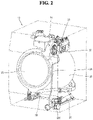
- FIG. 2 is a perspective view showing an interior view of a washing machine including a fluid channel switching pump according to an embodiment of the present disclosure.
- the washing machine 10 includes a cabinet 11 defining an exterior, a tub 18 accommodated in the cabinet 11, and a drum 21 which is rotatably mounted inside the tub 18 and into which laundry is put.
- a cabinet 11 defining an exterior, a tub 18 accommodated in the cabinet 11, and a drum 21 which is rotatably mounted inside the tub 18 and into which laundry is put.
- it includes the drum 21, a heat exchanger, and a fan motor 17, and includes a compressor 16 and a compressor support (not shown) for supporting the compressor 16.
- the washing machine 10 includes a fluid channel switching pump 100, a drain hose 20, and a drain connection pipe (not shown).
- the fluid channel switching pump 100 is located at the lower side of the washing machine 10.
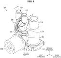
- the fluid channel switching pump 100 performs a circulation process of transferring wash water toward the tub via a first housing outlet 121 (see FIG. 3 ), a first inlet 131 (see FIG. 3 ) and a first outlet 135 (see FIG. 3 ) or a drainage process of discharging wash water to the outside via the second housing outlet 123 (see FIG. 3 ), the second inlet 133 (see FIG. 3 ) and the second outlet 137 (see FIG. 3 ) with a single motor 150 by driving the motor 150.
- the fluid channel switching pump 100 may include an inlet pipe 110, an impeller housing 120, a flow path switch 130, a diaphragm 140, and a motor 150.
- the fluid channel switching pump 100 is a pump that converts a flow path of a fluid, and may convert both gas and liquid flow paths. However, in order to help the understanding of the present disclosure, it may be described based on a liquid such as wash water.
- the inlet pipe 110 may store or transfer water for recirculation to the tub 18 (see FIG. 2 ) or water to be drained after washing is completed to the impeller housing 120.
- the water supplied to the inlet pipe 110 may be collectively defined as wash water.
- the inlet pipe 110 has a pipe shape, one side of which may be supplied with wash water from the tub 18 or the outside, and the other side of which may be closed with an openable stopper 111.
- the stopper 111 can be opened and closed according to the user's selection, and by removing the stopper 111, wash water accumulated in the inlet pipe 110 may be removed or foreign substances may be removed.
- a hole is formed in the outer circumferential surface of the inlet pipe 110 to communicate with the impeller housing 120.
- the inflow path of the wash water can be bent. Through this, it is possible to prevent foreign matters that may be mixed with the wash water from directly entering the impeller 125 (see FIG. 4 ) and causing damage.
- the inflow path of the wash water serves as a structural filter to make the foreign matters, which may cause serious damage to the impeller 125 due to the weight among the foreign matters introduced with the flow of the wash water, move to the stopper 111 and prevent them from entering the hole.
- the impeller housing 120 communicates with the hole formed on the outer circumferential surface of the inlet pipe 110 and may receive wash water through the hole.
- the impeller housing 120 may include an impeller 125 connected to the motor 150 and rotating in an arbitrary direction.
- the impeller 125 may rotate clockwise or counterclockwise according to the rotation direction of the motor 150.
- the flow of wash water in the fluid channel switching pump 100 may be changed.
- by controlling the rotation direction and speed of the motor 150 it may operate at a high speed during the draining process to quickly discharge water, and, during the circulation process, it may operate at a relatively low speed compared to the draining process to prevent unnecessary noise and power consumption.
- the impeller housing 120 may include a first housing outlet 121 and a second housing outlet 123.
- the first housing outlet 121 and the second housing outlet 123 may be formed in parallel in a direction tangential to the rotation direction of the impeller 125.
- the second housing outlet 123 may be formed parallel to the tangential direction when the impeller 125 rotates in the counterclockwise direction.
- the first housing outlet 121 and the second housing outlet 123 may be disposed to face the same direction.
- the connection with the flow path switch 130 to be described later and the inflow of wash water are facilitated, and the volume of the flow path switch 130 can be reduced.
- the flow path switch 130 may include a first inlet 131, a second inlet 133, a first outlet 135 and a second outlet 137.
- the first inlet 131 may be coupled to communicate with the first housing outlet 121
- the second inlet 133 may be coupled to communicate with the second housing outlet 123.
- the first inlet 131 and the second inlet 133 are extended along the direction of the first housing outlet 121 and the second housing outlet 123 to be supplied with wash water while minimizing the flow loss of the water flow generated by the impeller 125. Wash water introduced through the first inlet 131 may be discharged to the first outlet 135 through the internal space 139.
- the diaphragm 140 may be formed to block the second inlet 133 when the first inlet 131 is opened, and block the first inlet 131 when the second inlet 133 is opened. In other words, the diaphragm 140 may be formed to open only one out of the first flow path and the second flow path.
- a direction may be defined and used to aid understanding.
- the first direction is a direction facing the motor 150, the first housing outlet 121, and the second housing outlet 123 at the same time, and it may refer to a direction toward the lower left side based on the illustrated state of FIG. 3 .
- the second direction is perpendicular to the first direction and may refer to a direction facing upward based on the illustrated state of FIG. 3 .
- the third direction is a direction perpendicular to the first direction and the second direction, and may refer to a lower right direction based on the illustrated state shown in FIG. 3 .
- the direction definition as described above is only for aiding understanding of the present disclosure and is not absolute, and when one direction reference is changed, the other direction reference may be changed in response thereto.
- the flow pressure of the wash water can be prevented from sudden lowering and the pressure of the diaphragm 140 for closing the flow path on the other side can be maintained by reducing the width of the central portion 138 of the flow path switch 130.
- the width of the central portion 138 of the flow path switch 130 may be similar to the width of the first inlet 131 or the second inlet 133.
- the flow path switch 130 may have a circular shape when viewed from a third direction. It is formed in correspondence with the outer shape of the diaphragm 140 to be described later, and is coupled to be overlapped with a portion of the outermost portion 141 of the diaphragm 140, so that the path leading to the first housing outlet 121, the first inlet 131, and the first outlet 135 and the path leading to the second housing outlet 123, the second inlet 133, and the second outlet 137 can be distinguished.
- the diaphragm 140 may be formed of a rubber material that is circular and elastically deformable, and may have a shape of a circular plate with a protruding central portion having a gentle curvature.
- the diaphragm 140 may be formed such that the protruding direction is changed by 180° when a force of a certain amount or more is applied to the central portion. For example, when wash water flows into the first flow path, the central portion of the diaphragm 140 protrudes toward the second flow path due to the flow pressure, and abuts the central portion 138 of the flow path switch 130 to block the second housing outlet 123.
- the degree of protrusion of the central portion of the diaphragm 140 is such that the first housing outlet 121 or the second housing outlet 123 can be blocked.
- the central portion of the diaphragm 140 may contact the sealing line 134 to be described later, or the central portion may protrude to be pressed by a predetermined degree.
- the central portion of the diaphragm 140 protrudes while forming a gentle curvature, and the flow path switch 130 is gradually widened again from the central portion 138 toward the second direction, the flow loss of the wash water can be minimized.
- the flow path switch 130 may be divided into two parts around the diaphragm 140. For example, it may be divided into a part forming a first flow path and a part forming a second flow path.
- the flow path switch 130 may be coupled with the diaphragm 140 interposed therebetween and overlapped with a portion of the outermost portion 141 of the diaphragm 140, and the overlapping portion of the outermost portion 141 and the flow path switch may form a closed curve. As described above, it is coupled with the diaphragm 140 in an overlapping state with a portion of the outermost portion 141 to separate the first flow path and the second flow path, and at the same time, seal the coupling portion of the two parts to prevent leakage.
- the assembly of the flow path switch 130 may be performed, for example, by rotating the diaphragm 140 in a state in which circularly formed portions are brought into contact with each other to be assembled.
- it is not limited to this method and any method capable of combining two parts may be applied in various ways.
- a sealing line 134 may be formed on an inner surface of the central portion 138 of the flow path switch 130 according to an embodiment.
- the sealing line 134 forms a band from the inner surface of the central portion 138 and protrudes, and may form a ring shape when two parts of the flow path switch 130 are assembled.
- the sealing line 134 may be formed corresponding to the protruding shape of the diaphragm 140.
- the sealing line 134 and the diaphragm 140 may be in line contact with each other, or may be in contact with each other for the center of the diaphragm 140 to be pressed by a predetermined degree.
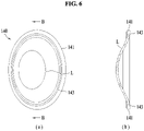
- FIG. 6 is a view showing a diaphragm 140 according to an embodiment of the present disclosure. More specifically, (a) of FIG. 6 is a perspective view of the diaphragm 140, and (b) of FIG. 6 is a cross-sectional view taken along line B-B of (a) of FIG. 6 .
- the diaphragm 140 may be formed of a rubber material that is elastically deformable, and may have a shape of a circular plate with a protruding central portion forming a gentle curvature.
- the diaphragm 140 is pre-formed to maintain the protruding shape of the central portion, and it may be formed such that the protruding direction is changed by 180° when a force of a certain amount or more is applied to the central portion.
- the diaphragm 140 maintains a protruding state in one direction, either side of the first flow path or the second flow path may be closed and the other side may be open.
- the diaphragm 140 By pre-forming the diaphragm 140 to close one flow path, it is possible to greatly reduce the flow pressure of the wash water required to close the flow path on one side. Through this, not only the durability of the diaphragm 140 can be increased, it is possible to more reliably close any one side of the flow path and prevent reverse flow of wash water.
- the central portion of the diaphragm 140 protrudes while forming a gentle curvature in a continuous shape, but the curvature may be changed at least once. For example, it may be deformed so that the amount of protrusion of the central portion decreases with respect to the reference line L shown in (a) of FIG. 6 and (b) of FIG. 6 .
- the curvature is formed large to protrude rapidly so that the amount of protrusion is larger than that of the central portion. Accordingly, the change in the protruding direction of the diaphragm 140 can be made more clearly.
- the curvature is formed to be relatively small so that the amount of protrusion is relatively small, so that the change in the path of the first flow path or the second flow path is made as smooth as possible, thereby minimizing flow loss.
- the diaphragm 140 is formed to have a uniform thickness as a whole, and a coupling portion 141 may be formed with a thickness thicker than other portions at the outermost portion 141.
- the flow path switch 130 is coupled with the diaphragm 140 interposed therebetween and overlapped with a portion of the outermost portion 141 of the diaphragm 140 so that the coupling portion of the two parts are sealed to prevent leakage. Accordingly, the durability and sealing force of the diaphragm 140 can be increased by forming a thick overlapping portion of the outermost portion 141.
- Adjacent to the outermost portion 141 of the diaphragm 140 according to an embodiment may be formed a bent portion 143 having a thickness thinner than that of other portions.
- the diaphragm 140 is formed to be converted by the flow pressure of the wash water flowing through the first flow path or the second flow path without disposing a separate actuator for changing the protruding direction.
- the rotational speed of the motor 150 it can be controlled to rotate quickly when draining and to rotate relatively slowly during circulation.
- the flow pressure of the wash water may be lowered.
- a thin portion such as the bent portion 143 may be provided to facilitate the conversion of the protruding direction of the diaphragm 140.
- FIG. 7 is a perspective view of a fluid channel switching pump 700 according to another embodiment of the present disclosure
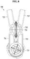
- FIG. 8 is a cross-sectional view taken along line C-C of FIG. 7 .
- the fluid channel switching pump 700 may have a difference in the shape of the flow path switch 730 and the diaphragm 740.
- the flow path switch 730 is formed of two parts, which may be divided in a direction dividing the first and the second inlet 735 and 737 and the first and the second outlet 731 and 733. In other words, it may have a shape cut along a plane perpendicular to the second direction.
- a rubber ring 736 or a gasket 736 may be disposed to seal the parting line.
- a coupling ring 745 may be formed at the outermost portion 741.
- a coupling ring formed of a metal material or a plastic material having high rigidity may be disposed so that the coupling ring 745 is fitted in the assembly process of the flow path switch 730.
- FIG. 9 is a view showing a diaphragm according to another embodiment of the present disclosure. More specifically, (a) of FIG. 9 is a perspective view of the diaphragm 740, and (b) of FIG. 9 is a cross-sectional view taken along line D-D of (a) of FIG. 9 .
- the diaphragm 740 may have a shape in which wrinkles are formed while going from the outermost portion 741 to the central portion.
- the central portion does not protrude in any one direction in advance and may be located on the same plane as the outermost portion 741.
- wash water flows into the first flow path or the second flow path, it may be transformed to protrude to one side by the flow pressure of the wash water, and if there is no flow of wash water in the flow path, the central portion may be return to the position flush with the outermost portion 741.
Landscapes
- Engineering & Computer Science (AREA)
- General Engineering & Computer Science (AREA)
- Mechanical Engineering (AREA)
- Physics & Mathematics (AREA)
- Fluid Mechanics (AREA)
- Structures Of Non-Positive Displacement Pumps (AREA)
Abstract
Description
- This disclosure relates to relates to a fluid channel switching pump that forms two or more water flows with a single motor. One particular implementation relates to a pump disposed mainly in an electronic device such as a washing machine and used to drain or circulate wash water.
- A washing machine is an apparatus for putting clothes, bedclothes, and the like (hereinafter, also referred to as "laundry") into a drum and then removing contaminants adhered thereto via processes, such as, washing, rinsing, dehydration, and drying. Washing machines are classified as a top loading type and a front loading type according to the type of putting laundry into a drum. The front loading type washing machine is generally referred to as a drum washing machine.
- The washing process of the drum washing machine may include an operation of circulating water in the drum and an operation of draining water after washing. A circulation pump and a drainage pump are provided for circulation and drainage operations, respectively. Conventionally, it was common to configure pumps for circulation and drainage with separate motors. In this case, there is a problem that the installation space is limited, and a plurality of motors are required, which is not cost effective.
-
Korean Patent Application Publication No. 10-2008-0046066 - According to the prior art document, a single motor and an impeller are configured to switch the rotation direction of the impeller to serve as two pumps. However, the structure is complex, making it difficult to assemble. Also, the direction of the flow path is rapidly changed (e.g., right angle or acute angle), causing a large flow loss. In addition, when the diaphragm is not elastically deformed sufficiently, blocking of one side of the flow path may be insufficient, and thus a problem of flowing backward toward an unwanted flow path may occur. In addition, since a force is applied to the diaphragm to induce a continuous elastic deformation, the diaphragm may be damaged or detached.
- The present disclosure has been made in view of the above problems, and it is an object of the present disclosure to provide a fluid channel switching pump capable of minimizing the flow loss of the wash water caused by the rotation of the impeller.
- Another object of the present disclosure is to provide a fluid channel switching pump that is easy to assemble by minimizing the number of parts.
- Yet another object of the present disclosure is to provide a fluid channel switching pump capable of preventing leakage of water in the flow path due to separation of the diaphragm or reverse flow toward another flow path.
- According to an embodiment of the present disclosure, a fluid channel switching pump including an inlet pipe configured to guide a flow of water, an impeller housing fluidly connected to the inlet pipe to receive water introduced from the inlet pipe, having an impeller built therein, and including a first housing outlet and a second housing outlet formed parallel to a tangential direction of rotation of the impeller, a flow path switch forming an internal space, including a first inlet and a second inlet, which communicate with the first housing outlet and the second housing outlet, respectively, and including a first outlet and a second outlet, which communicate with the first inlet and the second inlet, respectively, a diaphragm disposed in the internal space of the flow path switch, separating the first inlet and the second inlet, and separating the first outlet and the second outlet, and a motor connected to the impeller to transmit power. Through this, it is possible to use one impeller to perform the functions of two pumps. By continuously forming the first flow path leading to the first housing outlet, the first inlet and the first outlet and the second flow path the second housing outlet, the second inlet, and the second outlet, it is possible to minimize backflow and leakage flow loss.
- The first housing outlet and the second housing outlet may extend in a same direction.
- When viewed from a first direction, the flow path switch may be in a mortar shape whose width narrows gradually in a second direction perpendicular to the first direction and then widens again at a middle portion.
- When viewed from a third direction perpendicular to the first direction and the second direction, the flow path switch may be circular. This facilitates opening and closing of the first and second flow paths, and minimizes flow loss.
- The fluid channel switching pump may further include a sealing line that protrudes as a band from an inner side of the middle portion of the flow path switch toward the internal space.
- The flow path switch may include two parts that are disposed around the diaphragm, and when the flow path switch is assembled, at least a portion of the diaphragm is overlapped with the two parts and sandwiched between the two parts.
- A portion in which at least the portion of the diaphragm is overlapped with the flow path switch may form a closed curve. This facilitates assembly of the diaphragm and the flow path switch, and the number of parts can be reduced.
- The diaphragm may be formed of an elastic material, and be in a shape of a circular plate with a protruding central portion having a gentle curvature.
- A protruding direction of the diaphragm may be changed by 180° by an external force. This prevents the diaphragm from continuing in its elastic deformation state, thereby improving the durability of the diaphragm and improving the reliability of the flow path closure.
- The central portion of the diaphragm is sealed in contact with the sealing line of the flow path switch.
- The diaphragm may be formed continuously while protruding from an outermost portion to the central portion, and the curvature is changed at least once.
- The diaphragm may have a uniform thickness, and the diaphragm may include a coupling portion at the outermost portion, the coupling portion being thicker than other portions of the diaphragm. Through this, the sealing performance of the assembly part of the flow path switch can be improved.
- The diaphragm may be configured to selectively close a first flow path through the first housing outlet, the first inlet and the first switch outlet or a second flow path through the second housing outlet, the second inlet and the second switch outlet.
- The diaphragm may be formed of an elastic material, and may be in a shape of a circular plate with a protruding central portion and wrinkles.
- A protruding direction of the diaphragm may be changed by 180° by an external force.
- The diaphragm may have a uniform thickness, and the diaphragm may include a bent portion adjacent to the outermost portion, the bent portion being thinner than other portions of the diaphragm. Through this, it is possible to easily change the protruding direction of the diaphragm.
- At least one of the first outlet and the second outlet may be formed to be positioned on the same line as at least one of the first inlet and the second inlet.
- A fluid channel switching pump according to various embodiments of the present disclosure can minimize the flow loss of the wash water caused by the rotation of the impeller by forming a deformation angle of the flow path to be an obtuse angle.
- In the fluid channel switching pump according to various embodiments of the present disclosure, it is easy to assemble the diaphragm and the flow path switch, and the flow path switch is sealed at the same time as the assembly, thereby simplifying the structure.
- The fluid channel switching pump according to various embodiments of the present disclosure can prevent a continuous elastic deformation state from being maintained by using a diaphragm pre-formed in a specific shape.
-
-
FIG. 1 is a perspective view showing the appearance of a washing machine to which a fluid channel switching pump according to an embodiment of the present disclosure can be applied. -
FIG. 2 is a perspective view showing an interior view of a washing machine including a fluid channel switching pump according to an embodiment of the present disclosure. -
FIG. 3 is a perspective view of a fluid channel switching pump according to an embodiment of the present disclosure. -
FIG. 4 is a cross-sectional view taken along line A-A ofFIG. 3 . -
FIG. 5 is a view showing the interior of a flow path switch according to an embodiment of the present disclosure. - (a) of
FIG. 6 and (b) ofFIG. 6 are views showing a diaphragm according to an embodiment of the present disclosure. -
FIG. 7 is a perspective view of a fluid channel switching pump according to another embodiment of the present disclosure. -
FIG. 8 is a cross-sectional view taken along line C-C ofFIG. 7 . - (a) of
FIG. 9 and (b) ofFIG. 9 are views showing a diaphragm according to another embodiment of the present disclosure. - Hereinafter exemplary embodiments disclosed in the present specification will be described in detail with reference to the accompanying drawings, but identical or similar elements are denoted by the same reference numerals regardless of drawing numbers, and redundant descriptions thereof will be omitted. The suffixes "module" and "unit" for components used in the following description are given or used interchangeably in consideration of only the ease of preparation of the specification, and do not have meanings or roles that are distinguished from each other. In addition, in describing the embodiments disclosed in the present specification, when it is determined that a detailed description of related known technologies may obscure the gist of the embodiments disclosed in the present specification, the detailed description thereof will be omitted. In addition, the accompanying drawings are for easy understanding of the embodiments disclosed in the present specification, but the technical idea disclosed in the present specification is not limited by the accompanying drawings, and it should be understood to include all modifications, equivalents, or substitutes included in the spirit and scope of the present disclosure.
- Terms including an ordinal number such as first and second may be used to describe various elements, but the elements are not limited by the terms. These terms are used only for the purpose of distinguishing one component from another component.
- When a component is referred to as being "coupled" or "connected" to another component, it should be understood that it may be directly coupled or connected to the other component, but other components may exist in the middle. On the other hand, when a component is referred to as being "directly coupled" or "directly connected" to another component, it should be understood that there is no other component in the middle.
- Singular expressions include plural expressions unless the context clearly indicates otherwise.
- In the present application, terms such as "comprise" or "have" are intended to designate the presence of features, numbers, steps, actions, components, parts, or combinations thereof described in the specification, but it is to be understood that it does not preclude in advance the possibility of the presence or addition of one or more other features, numbers, steps, actions, components, parts, or combinations thereof.
-
FIG. 1 is a perspective view showing the appearance of a washing machine to which a fluid channel switching pump according to an embodiment of the present disclosure can be applied. - A
washing machine 10 includes acabinet 11 defining an exterior, adrum 21 which is rotatably mounted inside thecabinet 11 and into which laundry is put, a lifter (not shown) installed inside thedrum 21, and adoor 12 installed in front of thecabinet 11. In addition, a detergent inlet cover 13 for covering a detergent inlet is positioned at the lower side of thecabinet 11. - A storage container (not shown) that accommodates detergent and fabric softener and can be withdrawn to the outside of the
cabinet 11, a plurality of elastic members (not shown) and damper (not shown) that support thedrum 21 and suppress vibration, and a driving motor (not shown) for rotating thedrum 21 may be provided at the bottom of thewashing machine 10. In addition, adoor 12 may be provided on the front side of thecabinet 11 so that laundry to be washed can enter and exit. Thedoor 12 may be configured to open and close the front of thedrum 21. Thedoor 12 may be formed in a disc shape. An electric heater (not shown) capable of heating water when power is applied may be provided under thedrum 21. - A fluid channel switching pump (not shown) may be provided at the lower side of the
drum 21 to drain the wash water inside thedrum 21 or to circulate the water from thedrum 21 to flow into the upper area of thedrum 21. A plurality oflegs 14 that are spaced apart from the ground by a predetermined height to support thewashing machine 10 are positioned thereunder. -
FIG. 2 is a perspective view showing an interior view of a washing machine including a fluid channel switching pump according to an embodiment of the present disclosure. - The
washing machine 10 includes acabinet 11 defining an exterior, atub 18 accommodated in thecabinet 11, and adrum 21 which is rotatably mounted inside thetub 18 and into which laundry is put. In addition, it includes thedrum 21, a heat exchanger, and afan motor 17, and includes acompressor 16 and a compressor support (not shown) for supporting thecompressor 16. In addition, thewashing machine 10 includes a fluidchannel switching pump 100, adrain hose 20, and a drain connection pipe (not shown). - The fluid
channel switching pump 100 according to an embodiment of the present disclosure is located at the lower side of thewashing machine 10. The fluidchannel switching pump 100 performs a circulation process of transferring wash water toward the tub via a first housing outlet 121 (seeFIG. 3 ), a first inlet 131 (seeFIG. 3 ) and a first outlet 135 (seeFIG. 3 ) or a drainage process of discharging wash water to the outside via the second housing outlet 123 (seeFIG. 3 ), the second inlet 133 (seeFIG. 3 ) and the second outlet 137 (seeFIG. 3 ) with asingle motor 150 by driving themotor 150. -
FIG. 3 is a perspective view of a fluid channel switching pump 200 according to an embodiment of the present disclosure, andFIG. 4 is a cross-sectional view taken along line A-A ofFIG. 3 . - Referring to
FIGS. 3 and4 , the fluidchannel switching pump 100 according to an embodiment of the present disclosure may include aninlet pipe 110, animpeller housing 120, a flow path switch 130, adiaphragm 140, and amotor 150. - The fluid
channel switching pump 100 according to an embodiment is a pump that converts a flow path of a fluid, and may convert both gas and liquid flow paths. However, in order to help the understanding of the present disclosure, it may be described based on a liquid such as wash water. - The
inlet pipe 110 according to an embodiment may store or transfer water for recirculation to the tub 18 (seeFIG. 2 ) or water to be drained after washing is completed to theimpeller housing 120. The water supplied to theinlet pipe 110 may be collectively defined as wash water. Theinlet pipe 110 has a pipe shape, one side of which may be supplied with wash water from thetub 18 or the outside, and the other side of which may be closed with anopenable stopper 111. Thestopper 111 can be opened and closed according to the user's selection, and by removing thestopper 111, wash water accumulated in theinlet pipe 110 may be removed or foreign substances may be removed. A hole is formed in the outer circumferential surface of theinlet pipe 110 to communicate with theimpeller housing 120. By forming the hole for connecting to theimpeller housing 120 on the outer circumferential surface of theinlet pipe 110, the inflow path of the wash water can be bent. Through this, it is possible to prevent foreign matters that may be mixed with the wash water from directly entering the impeller 125 (seeFIG. 4 ) and causing damage. In other words, by bending the inflow path of the wash water once, it serves as a structural filter to make the foreign matters, which may cause serious damage to theimpeller 125 due to the weight among the foreign matters introduced with the flow of the wash water, move to thestopper 111 and prevent them from entering the hole. - The
impeller housing 120 according to an embodiment communicates with the hole formed on the outer circumferential surface of theinlet pipe 110 and may receive wash water through the hole. Theimpeller housing 120 may include animpeller 125 connected to themotor 150 and rotating in an arbitrary direction. For example, theimpeller 125 may rotate clockwise or counterclockwise according to the rotation direction of themotor 150. According to the rotation direction of theimpeller 125 as described above, the flow of wash water in the fluidchannel switching pump 100 may be changed. In addition, by controlling the rotation direction and speed of themotor 150, it may operate at a high speed during the draining process to quickly discharge water, and, during the circulation process, it may operate at a relatively low speed compared to the draining process to prevent unnecessary noise and power consumption. - The
impeller housing 120 according to an embodiment may include afirst housing outlet 121 and asecond housing outlet 123. Thefirst housing outlet 121 and thesecond housing outlet 123 may be formed in parallel in a direction tangential to the rotation direction of theimpeller 125. For example, if thefirst housing outlet 121 is formed parallel to the tangential direction when theimpeller 125 rotates in the clockwise direction, thesecond housing outlet 123 may be formed parallel to the tangential direction when theimpeller 125 rotates in the counterclockwise direction. By disposing thefirst housing outlet 121 and thesecond housing outlet 123 in parallel in directions tangential to the rotation directions of theimpeller 125, the flow loss of the wash water generated by theimpeller 125 can be minimized. - The
first housing outlet 121 and thesecond housing outlet 123 according to an embodiment may be disposed to face the same direction. By arranging thefirst housing outlet 121 and thesecond housing outlet 123 to face the same direction, the connection with the flow path switch 130 to be described later and the inflow of wash water are facilitated, and the volume of the flow path switch 130 can be reduced. - The flow path switch 130 according to an embodiment may include a
first inlet 131, asecond inlet 133, afirst outlet 135 and asecond outlet 137. Thefirst inlet 131 according to an embodiment may be coupled to communicate with thefirst housing outlet 121, and thesecond inlet 133 may be coupled to communicate with thesecond housing outlet 123. Thefirst inlet 131 and thesecond inlet 133 are extended along the direction of thefirst housing outlet 121 and thesecond housing outlet 123 to be supplied with wash water while minimizing the flow loss of the water flow generated by theimpeller 125. Wash water introduced through thefirst inlet 131 may be discharged to thefirst outlet 135 through theinternal space 139. As described above, a flow path leading to thefirst housing outlet 121, thefirst inlet 131 and thefirst outlet 135 may be defined as a first flow path. In addition, the wash water introduced through thesecond inlet 133 may be discharged to thesecond outlet 137 through theinternal space 139. As described above, a flow path leading to thesecond housing outlet 123, thesecond inlet 133, and thesecond outlet 137 may be defined as a second flow path. Theinternal space 139 of the flow path switch 130 is divided by adiaphragm 140 to be described later to prevent mixing of the wash water entered through thefirst inlet 131 and the wash water entered through thesecond inlet 133. In addition, thediaphragm 140 may be formed to block thesecond inlet 133 when thefirst inlet 131 is opened, and block thefirst inlet 131 when thesecond inlet 133 is opened. In other words, thediaphragm 140 may be formed to open only one out of the first flow path and the second flow path. - As described above, different water flows are generated in the two flow paths according to the rotation direction of the
impeller 125 to supply wash water, so that onemotor 150 can serve as two pumps. For example, when thefirst outlet 135 is connected to a circulation pipe (not shown) connected to thetub 18, it can serve as a circulation pump, and, when thesecond outlet 137 is connected to a drain hose 20 (refer toFIG. 2 ), it can serve as a drainage pump. - In describing the fluid
channel switching pump 100 according to an embodiment of the present disclosure, a direction may be defined and used to aid understanding. For example, the first direction is a direction facing themotor 150, thefirst housing outlet 121, and thesecond housing outlet 123 at the same time, and it may refer to a direction toward the lower left side based on the illustrated state ofFIG. 3 . The second direction is perpendicular to the first direction and may refer to a direction facing upward based on the illustrated state ofFIG. 3 . The third direction is a direction perpendicular to the first direction and the second direction, and may refer to a lower right direction based on the illustrated state shown inFIG. 3 . - The direction definition as described above is only for aiding understanding of the present disclosure and is not absolute, and when one direction reference is changed, the other direction reference may be changed in response thereto.
- When viewed from the first direction, the flow path switch 130 according to an embodiment may be formed in a mortar shape that becomes narrower in width while extending in the second direction and then becomes wider again in the
central portion 138. As described above, the flow path switch 130 is formed to close one flow path when the other flow path is opened by the built-indiaphragm 140. At this time, if the flow path switch 130 is formed to have the same width, when one flow path is opened to close the other flow path, one flow path is widened. In this case, a large flow loss may occur due to the sudden expansion of the flow path. In addition, the force to pressurize thediaphragm 140 is reduced, so that the force to close the other flow path is insufficient, and the wash water may flow back to the other flow path. Accordingly, in the present disclosure, even if thediaphragm 140 opens one flow path and closes the other flow path, the flow pressure of the wash water can be prevented from sudden lowering and the pressure of thediaphragm 140 for closing the flow path on the other side can be maintained by reducing the width of thecentral portion 138 of the flow path switch 130. For example, the width of thecentral portion 138 of the flow path switch 130 may be similar to the width of thefirst inlet 131 or thesecond inlet 133. By gradually decreasing the width of thecentral portion 138 of the flow path switch 130, rapid change of the flow path can be prevented, thereby minimizing flow pressure loss of wash water. - The flow path switch 130 according to an embodiment may have a circular shape when viewed from a third direction. It is formed in correspondence with the outer shape of the
diaphragm 140 to be described later, and is coupled to be overlapped with a portion of theoutermost portion 141 of thediaphragm 140, so that the path leading to thefirst housing outlet 121, thefirst inlet 131, and thefirst outlet 135 and the path leading to thesecond housing outlet 123, thesecond inlet 133, and thesecond outlet 137 can be distinguished. - The
diaphragm 140 according to an embodiment may be formed of a rubber material that is circular and elastically deformable, and may have a shape of a circular plate with a protruding central portion having a gentle curvature. Thediaphragm 140 may be formed such that the protruding direction is changed by 180° when a force of a certain amount or more is applied to the central portion. For example, when wash water flows into the first flow path, the central portion of thediaphragm 140 protrudes toward the second flow path due to the flow pressure, and abuts thecentral portion 138 of the flow path switch 130 to block thesecond housing outlet 123. The degree of protrusion of the central portion of thediaphragm 140 is such that thefirst housing outlet 121 or thesecond housing outlet 123 can be blocked. For example, the central portion of thediaphragm 140 may contact thesealing line 134 to be described later, or the central portion may protrude to be pressed by a predetermined degree. As the central portion of thediaphragm 140 protrudes while forming a gentle curvature, and the flow path switch 130 is gradually widened again from thecentral portion 138 toward the second direction, the flow loss of the wash water can be minimized. -
FIG. 5 is a view showing the interior of a flow path switch 130 according to an embodiment of the present disclosure. More specifically, it is a view in which a partial configuration of the flow path switch 130 is omitted. - The flow path switch 130 according to an embodiment may be divided into two parts around the
diaphragm 140. For example, it may be divided into a part forming a first flow path and a part forming a second flow path. The flow path switch 130 may be coupled with thediaphragm 140 interposed therebetween and overlapped with a portion of theoutermost portion 141 of thediaphragm 140, and the overlapping portion of theoutermost portion 141 and the flow path switch may form a closed curve. As described above, it is coupled with thediaphragm 140 in an overlapping state with a portion of theoutermost portion 141 to separate the first flow path and the second flow path, and at the same time, seal the coupling portion of the two parts to prevent leakage. The assembly of the flow path switch 130 may be performed, for example, by rotating thediaphragm 140 in a state in which circularly formed portions are brought into contact with each other to be assembled. However, it is not limited to this method and any method capable of combining two parts may be applied in various ways. - A
sealing line 134 may be formed on an inner surface of thecentral portion 138 of the flow path switch 130 according to an embodiment. Thesealing line 134 forms a band from the inner surface of thecentral portion 138 and protrudes, and may form a ring shape when two parts of the flow path switch 130 are assembled. Thesealing line 134 may be formed corresponding to the protruding shape of thediaphragm 140. As described above, thesealing line 134 and thediaphragm 140 may be in line contact with each other, or may be in contact with each other for the center of thediaphragm 140 to be pressed by a predetermined degree. -
FIG. 6 is a view showing adiaphragm 140 according to an embodiment of the present disclosure. More specifically, (a) ofFIG. 6 is a perspective view of thediaphragm 140, and (b) ofFIG. 6 is a cross-sectional view taken along line B-B of (a) ofFIG. 6 . - Referring to (a) of
FIG. 6 and (b) ofFIG. 6 , thediaphragm 140 according to an embodiment may be formed of a rubber material that is elastically deformable, and may have a shape of a circular plate with a protruding central portion forming a gentle curvature. Thediaphragm 140 is pre-formed to maintain the protruding shape of the central portion, and it may be formed such that the protruding direction is changed by 180° when a force of a certain amount or more is applied to the central portion. As thediaphragm 140 maintains a protruding state in one direction, either side of the first flow path or the second flow path may be closed and the other side may be open. By pre-forming thediaphragm 140 to close one flow path, it is possible to greatly reduce the flow pressure of the wash water required to close the flow path on one side. Through this, not only the durability of thediaphragm 140 can be increased, it is possible to more reliably close any one side of the flow path and prevent reverse flow of wash water. The central portion of thediaphragm 140 protrudes while forming a gentle curvature in a continuous shape, but the curvature may be changed at least once. For example, it may be deformed so that the amount of protrusion of the central portion decreases with respect to the reference line L shown in (a) ofFIG. 6 and (b) ofFIG. 6 . In theoutermost portion 141 of thediaphragm 140, the curvature is formed large to protrude rapidly so that the amount of protrusion is larger than that of the central portion. Accordingly, the change in the protruding direction of thediaphragm 140 can be made more clearly. In the central portion of thediaphragm 140, the curvature is formed to be relatively small so that the amount of protrusion is relatively small, so that the change in the path of the first flow path or the second flow path is made as smooth as possible, thereby minimizing flow loss. - The
diaphragm 140 according to an embodiment is formed to have a uniform thickness as a whole, and acoupling portion 141 may be formed with a thickness thicker than other portions at theoutermost portion 141. As described above, the flow path switch 130 is coupled with thediaphragm 140 interposed therebetween and overlapped with a portion of theoutermost portion 141 of thediaphragm 140 so that the coupling portion of the two parts are sealed to prevent leakage. Accordingly, the durability and sealing force of thediaphragm 140 can be increased by forming a thick overlapping portion of theoutermost portion 141. Adjacent to theoutermost portion 141 of thediaphragm 140 according to an embodiment may be formed abent portion 143 having a thickness thinner than that of other portions. In particular, thediaphragm 140 is formed to be converted by the flow pressure of the wash water flowing through the first flow path or the second flow path without disposing a separate actuator for changing the protruding direction. However, as described above, by controlling the rotational speed of themotor 150, it can be controlled to rotate quickly when draining and to rotate relatively slowly during circulation. When themotor 150 rotates slowly, the flow pressure of the wash water may be lowered. Even in this case, a thin portion such as thebent portion 143 may be provided to facilitate the conversion of the protruding direction of thediaphragm 140. -
FIG. 7 is a perspective view of a fluidchannel switching pump 700 according to another embodiment of the present disclosure, andFIG. 8 is a cross-sectional view taken along line C-C ofFIG. 7 . - In describing the fluid
channel switching pump 700 according to another embodiment of the present disclosure, in order to aid understanding of the present disclosure, the difference compared to the fluidchannel switching pump 100 ofFIGS. 1 to 6 may be mainly described. The same or similar reference numerals may also be used for the same or similar components compared to the fluidchannel switching pump 100 ofFIGS. 1 to 6 . - The fluid
channel switching pump 700 according to another embodiment of the present disclosure may have a difference in the shape of the flow path switch 730 and thediaphragm 740. - The flow path switch 730 according to another embodiment is formed of two parts, which may be divided in a direction dividing the first and the
second inlet second outlet rubber ring 736 or agasket 736 may be disposed to seal the parting line. - In the
diaphragm 740 according to another embodiment, acoupling ring 745 may be formed at theoutermost portion 741. In the case of thediaphragm 740, since it is formed of an elastic material, it may be difficult to fix the position within the flow path switch 730 only by its own shape. Accordingly, a coupling ring formed of a metal material or a plastic material having high rigidity may be disposed so that thecoupling ring 745 is fitted in the assembly process of the flow path switch 730. -
FIG. 9 is a view showing a diaphragm according to another embodiment of the present disclosure. More specifically, (a) ofFIG. 9 is a perspective view of thediaphragm 740, and (b) ofFIG. 9 is a cross-sectional view taken along line D-D of (a) ofFIG. 9 . - The
diaphragm 740 according to another embodiment may have a shape in which wrinkles are formed while going from theoutermost portion 741 to the central portion. In addition, the central portion does not protrude in any one direction in advance and may be located on the same plane as theoutermost portion 741. When wash water flows into the first flow path or the second flow path, it may be transformed to protrude to one side by the flow pressure of the wash water, and if there is no flow of wash water in the flow path, the central portion may be return to the position flush with theoutermost portion 741. - It will be apparent to those skilled in the art that various modifications and variations can be made in the present disclosure without departing from the spirit or scope of the disclosure.
- The above detailed description should not be construed as restrictive in all respects and should be considered as illustrative. The scope of the present disclosure should be determined by reasonable interpretation of the appended claims, and all modifications within the equivalent scope of the present disclosure are included in the scope of the present disclosure.
Claims (20)
- A fluid channel switching pump comprising:an inlet pipe configured to guide a flow of water;an impeller housing fluidly connected to the inlet pipe to receive water introduced from the inlet pipe, having an impeller built therein, and including a first housing outlet and a second housing outlet formed parallel to a tangential direction of rotation of the impeller;a flow path switch forming an internal space, including a first inlet and a second inlet, which communicate with the first housing outlet and the second housing outlet, respectively, and including a first outlet and a second outlet, which communicate with the first inlet and the second inlet, respectively;a diaphragm disposed in the internal space of the flow path switch, separating the first inlet and the second inlet, and separating the first outlet and the second outlet; anda motor connected to the impeller to transmit power.
- The fluid channel switching pump of claim 1, wherein the first housing outlet and the second housing outlet extend in a same direction.
- The fluid channel switching pump of claim 2, wherein, when viewed from a first direction, the flow path switch is in a mortar shape whose width narrows gradually in a second direction perpendicular to the first direction and then widens again at a middle portion.
- The fluid channel switching pump of claim 3, wherein, when viewed from a third direction perpendicular to the first direction and the second direction, the flow path switch is circular.
- The fluid channel switching pump of claim 3, further comprising: a sealing line that protrudes as a band from an inner side of the middle portion of the flow path switch toward the internal space.
- The fluid channel switching pump of claim 1, wherein the flow path switch includes two parts that are disposed around the diaphragm, and wherein when the flow path switch is assembled, at least a portion of the diaphragm is overlapped with the two parts and sandwiched between the two parts.
- The fluid channel switching pump of claim 6, wherein a portion in which at least the portion of the diaphragm is overlapped with the flow path switch forms a closed curve.
- The fluid channel switching pump of claim 1, wherein the diaphragm is formed of an elastic material, and is in a shape of a circular plate with a protruding central portion having a gentle curvature.
- The fluid channel switching pump of claim 8, wherein a protruding direction of the diaphragm is changed by 180° by an external force.
- The fluid channel switching pump of claim 5, wherein the central portion of the diaphragm is sealed in contact with the sealing line of the flow path switch.
- The fluid channel switching pump of claim 8, wherein the diaphragm is formed continuously while protruding from an outermost portion to the central portion, and the curvature is changed at least once.
- The fluid channel switching pump of claim 11, wherein the diaphragm has a uniform thickness, and wherein the diaphragm includes a coupling portion at the outermost portion, the coupling portion being thicker than other portions of the diaphragm.
- The fluid channel switching pump of claim 12, wherein the flow path switch includes two parts that are disposed around the diaphragm, and wherein when the flow path switch is assembled, the coupling portion of the diaphragm is overlapped with the two parts and sandwiched between the two parts.
- The fluid channel switching pump of claim 13, wherein the diaphragm is configured to selectively close a first flow path through the first housing outlet, the first inlet and the first switch outlet or a second flow path through the second housing outlet, the second inlet and the second switch outlet.
- The fluid channel switching pump of claim 1, wherein the diaphragm is formed of an elastic material, and is in a shape of a circular plate with a protruding central portion and wrinkles.
- The fluid channel switching pump of claim 15, wherein a protruding direction of the diaphragm is changed by 180° by an external force.
- The fluid channel switching pump of claim 12, wherein the diaphragm has a uniform thickness, and wherein the diaphragm includes a bent portion adjacent to the outermost portion, the bent portion being thinner than other portions of the diaphragm.
- The fluid channel switching pump of claim 1, wherein at least one of the first switch outlet and the second switch outlet is formed to be positioned on a same line as at least one of the first inlet and the second inlet.
- The fluid channel switching pump of claim 1, wherein, when the motor rotates the impeller clockwise, the diaphragm protrudes in a direction blocking the second housing outlet, the second inlet and the second outlet by a water flow leading to the first housing outlet, the first inlet and the first outlet.
- The fluid channel switching pump of claim 1, wherein, when the motor rotates the impeller counterclockwise, the diaphragm protrudes in a direction blocking the first housing outlet, the first inlet and the first outlet by a water flow leading to the second housing outlet, the second inlet and the second outlet.
Applications Claiming Priority (4)
| Application Number | Priority Date | Filing Date | Title |
|---|---|---|---|
| KR1020190144269A KR102296054B1 (en) | 2019-11-12 | 2019-11-12 | Folw path conversion pump |
| KR1020200002228A KR102894953B1 (en) | 2020-01-07 | 2020-01-07 | Folw path conversion pump |
| KR1020200002229A KR102894966B1 (en) | 2020-01-07 | 2020-01-07 | Folw path conversion pump |
| PCT/KR2020/015195 WO2021096140A1 (en) | 2019-11-12 | 2020-11-03 | Fluid channel switching pump |
Publications (3)
| Publication Number | Publication Date |
|---|---|
| EP4060113A1 true EP4060113A1 (en) | 2022-09-21 |
| EP4060113A4 EP4060113A4 (en) | 2023-12-06 |
| EP4060113B1 EP4060113B1 (en) | 2025-02-26 |
Family
ID=75847398
Family Applications (1)
| Application Number | Title | Priority Date | Filing Date |
|---|---|---|---|
| EP20887988.2A Active EP4060113B1 (en) | 2019-11-12 | 2020-11-03 | Fluid channel switching pump |
Country Status (5)
| Country | Link |
|---|---|
| US (1) | US12215694B2 (en) |
| EP (1) | EP4060113B1 (en) |
| CN (1) | CN114729494B (en) |
| AU (1) | AU2020267236B2 (en) |
| WO (1) | WO2021096140A1 (en) |
Families Citing this family (1)
| Publication number | Priority date | Publication date | Assignee | Title |
|---|---|---|---|---|
| TWI872806B (en) * | 2023-11-15 | 2025-02-11 | 安索鋼鋁有限公司 | Heat-dissipating device for remote control model |
Family Cites Families (25)
| Publication number | Priority date | Publication date | Assignee | Title |
|---|---|---|---|---|
| JPS5429317U (en) | 1977-08-01 | 1979-02-26 | ||
| JPS5647811U (en) | 1980-04-08 | 1981-04-28 | ||
| IT8353822U1 (en) * | 1983-10-14 | 1985-04-14 | Foredit Spa | DISTRIBUTOR DEVICE FOR BIDIRECTIONAL PUMPS, PARTICULARLY MOTOR VEHICLE WINDSCREEN WASHER PUMPS. |
| AU9083391A (en) * | 1990-12-21 | 1992-07-22 | Transpar Iberica, S.A. | Double membrane anti-overflow device for electric pumps of windshield washers |
| FR2703409B1 (en) * | 1993-04-02 | 1995-06-02 | Seim Ind | Bi-directional centrifugal pump. |
| DE4408380C2 (en) * | 1994-03-12 | 1997-07-31 | Vdo Schindling | Pump with two optional pressure outlets |
| KR100220407B1 (en) | 1996-10-28 | 1999-09-15 | 전주범 | Hot circulation pump having flow direction |
| US5984644A (en) * | 1997-12-16 | 1999-11-16 | Ford Motor Company | Dual output window washer pump for an automotive vehicle |
| CN2531195Y (en) * | 2002-01-15 | 2003-01-15 | 谢森源 | Air valve with automatic switch |
| KR100863541B1 (en) | 2006-11-21 | 2008-10-15 | 엠텍비젼 주식회사 | Synchronous Control Method of Dual Port Memory with Synchronous Control Device, Dual Port Memory System with Synchronous Control Device and Dual Port Memory System |
| KR101718561B1 (en) * | 2009-04-23 | 2017-03-21 | 그라코 미네소타 인크. | Overmolded diaphragm pump |
| JP5647811B2 (en) | 2010-04-23 | 2015-01-07 | 東洋ゴム工業株式会社 | Diaphragm for diaphragm valve and manufacturing method thereof |
| JP5543608B2 (en) * | 2010-10-05 | 2014-07-09 | 株式会社ニフコ | Fluid distribution valve, fluid supply system including the same, and control method thereof |
| FR2967954B1 (en) * | 2010-11-29 | 2012-12-14 | Peugeot Citroen Automobiles Sa | CIRCUIT FOR DISPENSING WASHER LIQUID FOR MOTOR VEHICLE |
| JP5731296B2 (en) * | 2011-06-28 | 2015-06-10 | 株式会社ハーマン | Dishwasher |
| JP5429317B2 (en) | 2012-03-12 | 2014-02-26 | 株式会社村田製作所 | Piezoelectric micro pump |
| KR101371044B1 (en) | 2012-03-27 | 2014-03-10 | 경남중천전화(주) | Conversion pump of water flow for washing machine |
| CN104061168B (en) * | 2013-03-22 | 2018-02-16 | 德昌电机(深圳)有限公司 | Pump |
| JP6267882B2 (en) | 2013-07-08 | 2018-01-24 | 株式会社ミツバ | Vehicle washer valve device and vehicle washer device |
| CN104279167B (en) * | 2014-10-23 | 2017-03-22 | 佛山市顺德区美的洗涤电器制造有限公司 | Motor pump and washing electric appliance with motor pump |
| KR101690079B1 (en) * | 2015-01-14 | 2016-12-28 | 인천대학교 산학협력단 | Pump |
| KR101735432B1 (en) * | 2015-12-02 | 2017-05-15 | 인천대학교 산학협력단 | Bi-directional pump |
| KR102677752B1 (en) * | 2016-12-27 | 2024-06-25 | 엘지전자 주식회사 | Drain pump |
| KR102577087B1 (en) * | 2016-12-27 | 2023-09-12 | 엘지전자 주식회사 | Drain pump for laundry treating apparatus |
| TWM548740U (en) * | 2017-05-12 | 2017-09-11 | Dyi Sheng Industry Co Ltd | Pneumatic dual-diaphragm pump using pressure difference to control direction change |
-
2020
- 2020-11-03 WO PCT/KR2020/015195 patent/WO2021096140A1/en not_active Ceased
- 2020-11-03 EP EP20887988.2A patent/EP4060113B1/en active Active
- 2020-11-03 CN CN202080078146.1A patent/CN114729494B/en active Active
- 2020-11-12 AU AU2020267236A patent/AU2020267236B2/en active Active
- 2020-11-12 US US17/096,366 patent/US12215694B2/en active Active
Also Published As
| Publication number | Publication date |
|---|---|
| CN114729494B (en) | 2024-03-29 |
| WO2021096140A1 (en) | 2021-05-20 |
| AU2020267236B2 (en) | 2024-06-13 |
| EP4060113A4 (en) | 2023-12-06 |
| US12215694B2 (en) | 2025-02-04 |
| AU2020267236A1 (en) | 2021-05-27 |
| US20210140437A1 (en) | 2021-05-13 |
| EP4060113B1 (en) | 2025-02-26 |
| CN114729494A (en) | 2022-07-08 |
Similar Documents
| Publication | Publication Date | Title |
|---|---|---|
| US9752267B2 (en) | Laundry treating apparatus | |
| CN108457052B (en) | Washing machine | |
| KR102821899B1 (en) | Clothes dryer | |
| CN105316890A (en) | Washing machine | |
| CN109689963B (en) | drain pump | |
| EP2712952B1 (en) | Washing machine | |
| AU2020277114B2 (en) | Clothes treating apparatus | |
| EP4060113B1 (en) | Fluid channel switching pump | |
| CN111945392A (en) | Drain pump reaches clothing processing apparatus including it | |
| KR102296054B1 (en) | Folw path conversion pump | |
| KR102894966B1 (en) | Folw path conversion pump | |
| KR20210089024A (en) | Folw path conversion pump | |
| EP4083301B1 (en) | Clothes treating apparatus | |
| KR102925627B1 (en) | Laundry treating apparatus | |
| AU2023381517A1 (en) | Washing machine ventilation control module and washing machine | |
| US7581552B2 (en) | Drive unit for dish washing machines | |
| KR20210099924A (en) | Laundry treating apparatus | |
| CN117242218A (en) | Washing and drying machine | |
| KR200358901Y1 (en) | Drum front of drum type washing machine | |
| KR20210099925A (en) | Laundry treating apparatus | |
| WO2022270040A1 (en) | Washing and drying machine | |
| KR20210108659A (en) | Folw path conversion pump | |
| KR20230001070U (en) | Diaphragm Operated Drain Pump Unit | |
| KR20220085380A (en) | Laundry Treatment Apparatus | |
| CN121712941A (en) | Clothing processing device |
Legal Events
| Date | Code | Title | Description |
|---|---|---|---|
| STAA | Information on the status of an ep patent application or granted ep patent |
Free format text: STATUS: THE INTERNATIONAL PUBLICATION HAS BEEN MADE |
|
| PUAI | Public reference made under article 153(3) epc to a published international application that has entered the european phase |
Free format text: ORIGINAL CODE: 0009012 |
|
| STAA | Information on the status of an ep patent application or granted ep patent |
Free format text: STATUS: REQUEST FOR EXAMINATION WAS MADE |
|
| 17P | Request for examination filed |
Effective date: 20220611 |
|
| AK | Designated contracting states |
Kind code of ref document: A1 Designated state(s): AL AT BE BG CH CY CZ DE DK EE ES FI FR GB GR HR HU IE IS IT LI LT LU LV MC MK MT NL NO PL PT RO RS SE SI SK SM TR |
|
| DAV | Request for validation of the european patent (deleted) | ||
| DAX | Request for extension of the european patent (deleted) | ||
| A4 | Supplementary search report drawn up and despatched |
Effective date: 20231107 |
|
| RIC1 | Information provided on ipc code assigned before grant |
Ipc: F04D 29/42 20060101ALI20231031BHEP Ipc: F04D 13/06 20060101ALI20231031BHEP Ipc: D06F 39/08 20060101AFI20231031BHEP |
|
| STAA | Information on the status of an ep patent application or granted ep patent |
Free format text: STATUS: EXAMINATION IS IN PROGRESS |
|
| 17Q | First examination report despatched |
Effective date: 20240430 |
|
| REG | Reference to a national code |
Ref legal event code: R079 Free format text: PREVIOUS MAIN CLASS: D06F0039080000 Ref country code: DE Ref legal event code: R079 Ref document number: 602020046986 Country of ref document: DE Free format text: PREVIOUS MAIN CLASS: D06F0039080000 Ipc: F04D0015000000 |
|
| GRAP | Despatch of communication of intention to grant a patent |
Free format text: ORIGINAL CODE: EPIDOSNIGR1 |
|
| STAA | Information on the status of an ep patent application or granted ep patent |
Free format text: STATUS: GRANT OF PATENT IS INTENDED |
|
| RIC1 | Information provided on ipc code assigned before grant |
Ipc: F04D 29/48 20060101ALI20240930BHEP Ipc: F04D 29/42 20060101ALI20240930BHEP Ipc: F04D 15/00 20060101AFI20240930BHEP |
|
| INTG | Intention to grant announced |
Effective date: 20241016 |
|
| GRAS | Grant fee paid |
Free format text: ORIGINAL CODE: EPIDOSNIGR3 |
|
| GRAA | (expected) grant |
Free format text: ORIGINAL CODE: 0009210 |
|
| STAA | Information on the status of an ep patent application or granted ep patent |
Free format text: STATUS: THE PATENT HAS BEEN GRANTED |
|
| AK | Designated contracting states |
Kind code of ref document: B1 Designated state(s): AL AT BE BG CH CY CZ DE DK EE ES FI FR GB GR HR HU IE IS IT LI LT LU LV MC MK MT NL NO PL PT RO RS SE SI SK SM TR |
|
| REG | Reference to a national code |
Ref country code: GB Ref legal event code: FG4D |
|
| REG | Reference to a national code |
Ref country code: CH Ref legal event code: EP |
|
| REG | Reference to a national code |
Ref country code: DE Ref legal event code: R096 Ref document number: 602020046986 Country of ref document: DE |
|
| REG | Reference to a national code |
Ref country code: IE Ref legal event code: FG4D |
|
| REG | Reference to a national code |
Ref country code: NL Ref legal event code: MP Effective date: 20250226 |
|
| PG25 | Lapsed in a contracting state [announced via postgrant information from national office to epo] |
Ref country code: RS Free format text: LAPSE BECAUSE OF FAILURE TO SUBMIT A TRANSLATION OF THE DESCRIPTION OR TO PAY THE FEE WITHIN THE PRESCRIBED TIME-LIMIT Effective date: 20250526 |
|
| PG25 | Lapsed in a contracting state [announced via postgrant information from national office to epo] |
Ref country code: FI Free format text: LAPSE BECAUSE OF FAILURE TO SUBMIT A TRANSLATION OF THE DESCRIPTION OR TO PAY THE FEE WITHIN THE PRESCRIBED TIME-LIMIT Effective date: 20250226 |
|
| PG25 | Lapsed in a contracting state [announced via postgrant information from national office to epo] |
Ref country code: PL Free format text: LAPSE BECAUSE OF FAILURE TO SUBMIT A TRANSLATION OF THE DESCRIPTION OR TO PAY THE FEE WITHIN THE PRESCRIBED TIME-LIMIT Effective date: 20250226 |
|
| PG25 | Lapsed in a contracting state [announced via postgrant information from national office to epo] |
Ref country code: ES Free format text: LAPSE BECAUSE OF FAILURE TO SUBMIT A TRANSLATION OF THE DESCRIPTION OR TO PAY THE FEE WITHIN THE PRESCRIBED TIME-LIMIT Effective date: 20250226 |
|
| REG | Reference to a national code |
Ref country code: LT Ref legal event code: MG9D |
|
| PG25 | Lapsed in a contracting state [announced via postgrant information from national office to epo] |
Ref country code: NO Free format text: LAPSE BECAUSE OF FAILURE TO SUBMIT A TRANSLATION OF THE DESCRIPTION OR TO PAY THE FEE WITHIN THE PRESCRIBED TIME-LIMIT Effective date: 20250526 Ref country code: IS Free format text: LAPSE BECAUSE OF FAILURE TO SUBMIT A TRANSLATION OF THE DESCRIPTION OR TO PAY THE FEE WITHIN THE PRESCRIBED TIME-LIMIT Effective date: 20250626 |
|
| PG25 | Lapsed in a contracting state [announced via postgrant information from national office to epo] |
Ref country code: NL Free format text: LAPSE BECAUSE OF FAILURE TO SUBMIT A TRANSLATION OF THE DESCRIPTION OR TO PAY THE FEE WITHIN THE PRESCRIBED TIME-LIMIT Effective date: 20250226 |
|
| PG25 | Lapsed in a contracting state [announced via postgrant information from national office to epo] |
Ref country code: HR Free format text: LAPSE BECAUSE OF FAILURE TO SUBMIT A TRANSLATION OF THE DESCRIPTION OR TO PAY THE FEE WITHIN THE PRESCRIBED TIME-LIMIT Effective date: 20250226 |
|
| PG25 | Lapsed in a contracting state [announced via postgrant information from national office to epo] |
Ref country code: PT Free format text: LAPSE BECAUSE OF FAILURE TO SUBMIT A TRANSLATION OF THE DESCRIPTION OR TO PAY THE FEE WITHIN THE PRESCRIBED TIME-LIMIT Effective date: 20250626 Ref country code: LV Free format text: LAPSE BECAUSE OF FAILURE TO SUBMIT A TRANSLATION OF THE DESCRIPTION OR TO PAY THE FEE WITHIN THE PRESCRIBED TIME-LIMIT Effective date: 20250226 |
|
| PG25 | Lapsed in a contracting state [announced via postgrant information from national office to epo] |
Ref country code: BG Free format text: LAPSE BECAUSE OF FAILURE TO SUBMIT A TRANSLATION OF THE DESCRIPTION OR TO PAY THE FEE WITHIN THE PRESCRIBED TIME-LIMIT Effective date: 20250226 Ref country code: GR Free format text: LAPSE BECAUSE OF FAILURE TO SUBMIT A TRANSLATION OF THE DESCRIPTION OR TO PAY THE FEE WITHIN THE PRESCRIBED TIME-LIMIT Effective date: 20250527 |
|
| REG | Reference to a national code |
Ref country code: AT Ref legal event code: MK05 Ref document number: 1770865 Country of ref document: AT Kind code of ref document: T Effective date: 20250226 |
|
| PG25 | Lapsed in a contracting state [announced via postgrant information from national office to epo] |
Ref country code: SE Free format text: LAPSE BECAUSE OF FAILURE TO SUBMIT A TRANSLATION OF THE DESCRIPTION OR TO PAY THE FEE WITHIN THE PRESCRIBED TIME-LIMIT Effective date: 20250226 |
|
| PG25 | Lapsed in a contracting state [announced via postgrant information from national office to epo] |
Ref country code: SM Free format text: LAPSE BECAUSE OF FAILURE TO SUBMIT A TRANSLATION OF THE DESCRIPTION OR TO PAY THE FEE WITHIN THE PRESCRIBED TIME-LIMIT Effective date: 20250226 |
|
| PG25 | Lapsed in a contracting state [announced via postgrant information from national office to epo] |
Ref country code: DK Free format text: LAPSE BECAUSE OF FAILURE TO SUBMIT A TRANSLATION OF THE DESCRIPTION OR TO PAY THE FEE WITHIN THE PRESCRIBED TIME-LIMIT Effective date: 20250226 |
|
| PG25 | Lapsed in a contracting state [announced via postgrant information from national office to epo] |
Ref country code: AT Free format text: LAPSE BECAUSE OF FAILURE TO SUBMIT A TRANSLATION OF THE DESCRIPTION OR TO PAY THE FEE WITHIN THE PRESCRIBED TIME-LIMIT Effective date: 20250226 |
|
| PG25 | Lapsed in a contracting state [announced via postgrant information from national office to epo] |
Ref country code: CZ Free format text: LAPSE BECAUSE OF FAILURE TO SUBMIT A TRANSLATION OF THE DESCRIPTION OR TO PAY THE FEE WITHIN THE PRESCRIBED TIME-LIMIT Effective date: 20250226 Ref country code: EE Free format text: LAPSE BECAUSE OF FAILURE TO SUBMIT A TRANSLATION OF THE DESCRIPTION OR TO PAY THE FEE WITHIN THE PRESCRIBED TIME-LIMIT Effective date: 20250226 |
|
| PG25 | Lapsed in a contracting state [announced via postgrant information from national office to epo] |
Ref country code: RO Free format text: LAPSE BECAUSE OF FAILURE TO SUBMIT A TRANSLATION OF THE DESCRIPTION OR TO PAY THE FEE WITHIN THE PRESCRIBED TIME-LIMIT Effective date: 20250226 |
|
| PG25 | Lapsed in a contracting state [announced via postgrant information from national office to epo] |
Ref country code: SK Free format text: LAPSE BECAUSE OF FAILURE TO SUBMIT A TRANSLATION OF THE DESCRIPTION OR TO PAY THE FEE WITHIN THE PRESCRIBED TIME-LIMIT Effective date: 20250226 |
|
| REG | Reference to a national code |
Ref country code: DE Ref legal event code: R097 Ref document number: 602020046986 Country of ref document: DE |
|
| PLBE | No opposition filed within time limit |
Free format text: ORIGINAL CODE: 0009261 |
|
| STAA | Information on the status of an ep patent application or granted ep patent |
Free format text: STATUS: NO OPPOSITION FILED WITHIN TIME LIMIT |
|
| PGFP | Annual fee paid to national office [announced via postgrant information from national office to epo] |
Ref country code: DE Payment date: 20251002 Year of fee payment: 6 |
|
| PGFP | Annual fee paid to national office [announced via postgrant information from national office to epo] |
Ref country code: IT Payment date: 20251002 Year of fee payment: 6 |
|
| 26N | No opposition filed |
Effective date: 20251127 |