EP4060018A1 - Extracellular potential measurement device - Google Patents
Extracellular potential measurement device Download PDFInfo
- Publication number
- EP4060018A1 EP4060018A1 EP20886240.9A EP20886240A EP4060018A1 EP 4060018 A1 EP4060018 A1 EP 4060018A1 EP 20886240 A EP20886240 A EP 20886240A EP 4060018 A1 EP4060018 A1 EP 4060018A1
- Authority
- EP
- European Patent Office
- Prior art keywords
- insulating film
- recess
- electrode wires
- opening
- cells
- Prior art date
- Legal status (The legal status is an assumption and is not a legal conclusion. Google has not performed a legal analysis and makes no representation as to the accuracy of the status listed.)
- Withdrawn
Links
Images



Classifications
-
- G—PHYSICS
- G01—MEASURING; TESTING
- G01N—INVESTIGATING OR ANALYSING MATERIALS BY DETERMINING THEIR CHEMICAL OR PHYSICAL PROPERTIES
- G01N33/00—Investigating or analysing materials by specific methods not covered by groups G01N1/00 - G01N31/00
- G01N33/48—Biological material, e.g. blood, urine; Haemocytometers
- G01N33/483—Physical analysis of biological material
- G01N33/487—Physical analysis of biological material of liquid biological material
- G01N33/48707—Physical analysis of biological material of liquid biological material by electrical means
- G01N33/48728—Investigating individual cells, e.g. by patch clamp, voltage clamp
-
- G—PHYSICS
- G01—MEASURING; TESTING
- G01N—INVESTIGATING OR ANALYSING MATERIALS BY DETERMINING THEIR CHEMICAL OR PHYSICAL PROPERTIES
- G01N15/00—Investigating characteristics of particles; Investigating permeability, pore-volume or surface-area of porous materials
- G01N15/10—Investigating individual particles
- G01N15/1031—Investigating individual particles by measuring electrical or magnetic effects
-
- C—CHEMISTRY; METALLURGY
- C12—BIOCHEMISTRY; BEER; SPIRITS; WINE; VINEGAR; MICROBIOLOGY; ENZYMOLOGY; MUTATION OR GENETIC ENGINEERING
- C12M—APPARATUS FOR ENZYMOLOGY OR MICROBIOLOGY; APPARATUS FOR CULTURING MICROORGANISMS FOR PRODUCING BIOMASS, FOR GROWING CELLS OR FOR OBTAINING FERMENTATION OR METABOLIC PRODUCTS, i.e. BIOREACTORS OR FERMENTERS
- C12M41/00—Means for regulation, monitoring, measurement or control, e.g. flow regulation
- C12M41/28—Means for regulation, monitoring, measurement or control, e.g. flow regulation of redox potential
-
- C—CHEMISTRY; METALLURGY
- C12—BIOCHEMISTRY; BEER; SPIRITS; WINE; VINEGAR; MICROBIOLOGY; ENZYMOLOGY; MUTATION OR GENETIC ENGINEERING
- C12M—APPARATUS FOR ENZYMOLOGY OR MICROBIOLOGY; APPARATUS FOR CULTURING MICROORGANISMS FOR PRODUCING BIOMASS, FOR GROWING CELLS OR FOR OBTAINING FERMENTATION OR METABOLIC PRODUCTS, i.e. BIOREACTORS OR FERMENTERS
- C12M41/00—Means for regulation, monitoring, measurement or control, e.g. flow regulation
- C12M41/46—Means for regulation, monitoring, measurement or control, e.g. flow regulation of cellular or enzymatic activity or functionality, e.g. cell viability
-
- B—PERFORMING OPERATIONS; TRANSPORTING
- B01—PHYSICAL OR CHEMICAL PROCESSES OR APPARATUS IN GENERAL
- B01L—CHEMICAL OR PHYSICAL LABORATORY APPARATUS FOR GENERAL USE
- B01L2300/00—Additional constructional details
- B01L2300/06—Auxiliary integrated devices, integrated components
- B01L2300/0627—Sensor or part of a sensor is integrated
- B01L2300/0645—Electrodes
-
- B—PERFORMING OPERATIONS; TRANSPORTING
- B01—PHYSICAL OR CHEMICAL PROCESSES OR APPARATUS IN GENERAL
- B01L—CHEMICAL OR PHYSICAL LABORATORY APPARATUS FOR GENERAL USE
- B01L2300/00—Additional constructional details
- B01L2300/06—Auxiliary integrated devices, integrated components
- B01L2300/0627—Sensor or part of a sensor is integrated
- B01L2300/0663—Whole sensors
-
- G—PHYSICS
- G01—MEASURING; TESTING
- G01N—INVESTIGATING OR ANALYSING MATERIALS BY DETERMINING THEIR CHEMICAL OR PHYSICAL PROPERTIES
- G01N15/00—Investigating characteristics of particles; Investigating permeability, pore-volume or surface-area of porous materials
- G01N15/01—Investigating characteristics of particles; Investigating permeability, pore-volume or surface-area of porous materials specially adapted for biological cells, e.g. blood cells
Definitions
- a three-dimensional collection of cells is stored in the recess with a varying size reducing downward, which is provided by overlapping the openings of the multiple insulating films stacked.
- An end of each of the electrode wires interposed between upper and lower insulating films is located near the opening in the insulating film immediately below it and is exposed in the recess, so that ends of the multiple electrode wires can be in contact with the three-dimensional collection of cells.
- the multiple electrode wires are arranged in multiple heights, i.e., in multiple layers, so that electric potentials at multiple points in different heights of the collection of cells can be measured.
- multiple through-holes 12P are formed for positioning the insulating films 11, 12, 13, and 14 to be laminated.
- the aforementioned electrode wires 12B and 12C are formed on the upper surface of the insulating film 12.
- Wide connection terminals 12T and 12CT are formed at the ends of the electrode wires 12B and 12C, which are opposite to the ends near the opening 12H.
- the length of insulating film 13 is less than that of the insulating film 14 immediately below it, and almost all of the electrode wire 14B formed on insulating film 14 is covered with and protected by the upper insulating film 13. However, the connection terminal 14T of the electrode wire 14B is exposed at least in part.
- the openings 11H and 21H are connected by the linear slit or groove 3 formed in the insulating film 11. Ends of the multiple axon electrode wires formed on the insulating film 12 immediately below the groove 3 are exposed in the groove 3 in the insulating film 11.
- the insulating film 11 without the portion 11X (the insulating film 11 having a penetrating recess corresponding to the portion 11X) is formed.
- the recess can be formed in the insulating film 11 by, for example, etching.
- the collection of cells disposed in the recess 2 may be a cell mass in vivo or a cell mass, an organoid, or a spheroid cultured in vitro.
- the extracellular potential measurement device 1 in addition to potentials of a collection of cells, potentials of an axon extending from the collection of cells can be measured. By analyzing the potentials, it is possible to study in vitro models that are useful for estimating signal transduction in neurons in vivo, and to evaluate, for example, drug effects and/or side effects on neurons.
- Only one axon electrode wire 30 may be provided. However, in this embodiment, multiple axon electrode wires 30 are provided, and potentials at multiple points in the length direction of the axon can be measured, enabling more detailed analysis.
- each of the second electrode wires are located near the second opening in the insulating film immediately below it and is exposed in the second recess 4A. More specifically, the second electrode wires 22B and 22C are formed on the insulating film 12, and ends of the second electrode wires 22B and 22C are located near the opening 22H of the insulating film 12 immediately below the second electrode wires 22B and 22C, and are exposed through the upper opening 21H.
- the second electrode wires 23B are formed on the insulating film 13, and ends of the second electrode wires 23B are located near the opening 23H in the insulating film 13 immediately below the second electrode wire 23B, and are exposed through the upper openings 21H and 22H.
Landscapes
- Chemical & Material Sciences (AREA)
- Health & Medical Sciences (AREA)
- Life Sciences & Earth Sciences (AREA)
- Engineering & Computer Science (AREA)
- Biomedical Technology (AREA)
- Organic Chemistry (AREA)
- Zoology (AREA)
- General Health & Medical Sciences (AREA)
- Biochemistry (AREA)
- Wood Science & Technology (AREA)
- Bioinformatics & Cheminformatics (AREA)
- Analytical Chemistry (AREA)
- Physics & Mathematics (AREA)
- Genetics & Genomics (AREA)
- Microbiology (AREA)
- Sustainable Development (AREA)
- Immunology (AREA)
- General Physics & Mathematics (AREA)
- General Engineering & Computer Science (AREA)
- Pathology (AREA)
- Biotechnology (AREA)
- Dispersion Chemistry (AREA)
- Biophysics (AREA)
- Cell Biology (AREA)
- Hematology (AREA)
- Molecular Biology (AREA)
- Urology & Nephrology (AREA)
- Food Science & Technology (AREA)
- Medicinal Chemistry (AREA)
- Apparatus Associated With Microorganisms And Enzymes (AREA)
- Investigating Or Analyzing Materials By The Use Of Electric Means (AREA)
Abstract
Description
- The present invention relates to extracellular potential measurement devices.
- In recent years, devices for measuring an extracellular potential of cell masses or spheroids, each of which is a collection of cells, in vitro have been developed (Patent Documents 1 and 2). Analyses of extracellular potentials are useful for evaluating drug effects and/or side effects on cells.
-
- Patent Document 1: International Publication
WO 2009/038079 - Patent Document 2: International Publication
WO 2011/010721 - The cell masses, organoids, or spheroids, each of which is a collection of cells, have a three-dimensional structure, and therefore, it is desirable to be able to measure electric potentials at multiple points in different heights. Furthermore, it is desirable that a device for measuring electric potentials can be easily manufactured. Therefore, there is a demand for an extracellular potential measuring device that can measure potentials at multiple points in different heights of a collection of cells and that can be easily manufactured.
- On the other hand, one or more linear axons may extend from a cell mass, organoid or spheroid that is a collection of cells related to neurons. Measuring potentials of axons as well as cell collections may contribute to analyses of the behavior of a nervous system in vivo. Therefore, there is a demand for an extracellular potential measurement device that can measure not only potentials of a collection of cells but also potentials of axons.
- Accordingly, the present disclosure solves any of the above problems.
- In accordance with an aspect of the disclosure, an extracellular potential measurement device includes multiple insulating films each of which is made from an electric insulating material, the insulating films being stacked and bonded to each other; and multiple electrode wires each of which is made from an electroconductive material, the electrode wires being arranged in multiple heights. Each of the electrode wires is interposed between an upper insulating film and a lower insulating film. Each of the insulating films, except for a lowermost insulating film, has an opening penetrating the insulating film. The opening in a lower insulating film has a size that is less than that of the opening in an upper insulating film, the openings in the insulating films being overlapped to form a recess having a size reducing downward, the recess being adapted to store a collection of cells. Each of the electrode wires has an end that is located near an opening in an insulating film that is immediately below the electrode wire, the ends being exposed in the recess.
- In this aspect, a three-dimensional collection of cells is stored in the recess with a varying size reducing downward, which is provided by overlapping the openings of the multiple insulating films stacked. An end of each of the electrode wires interposed between upper and lower insulating films is located near the opening in the insulating film immediately below it and is exposed in the recess, so that ends of the multiple electrode wires can be in contact with the three-dimensional collection of cells. The multiple electrode wires are arranged in multiple heights, i.e., in multiple layers, so that electric potentials at multiple points in different heights of the collection of cells can be measured.
- In addition, in the extracellular potential measurement device according to the aspect, multiple insulating films having openings are joined together to form the recess with a varying size reducing downward, which is suitable for storing a three-dimensional collection of cells, and electrode wires interposed between the multiple insulating films can be located at multiple heights. Accordingly, it is easy to manufacture the extracellular potential measurement device that can measure potentials at multiple points in different heights of the three-dimensional collection of cells. By laminating a large number of insulating films, it is possible to increase the number of heights in which electrode wires are provided and the number of electrode wires, so that detailed analyses of the collection of cells can be conducted.
- An extracellular potential measurement device according to another aspect of the present disclosure includes a sheet including multiple insulating films each of which is made from an electric insulating material, the insulating films being stacked and bonded to each other, the sheet further including a recess adapted to store a collection of cells and a groove connected to the recess, the groove being adapted to store a linear axon extending from the collection of cells; and multiple electrode wires interposed between the insulating films of the sheet. Each of the electrode wires has an end exposed in the recess so as to be brought into contact with the collection of cells. At least one electrode wire has an end exposed in the groove so as to be brought into contact with the axon.
- In this aspect, in addition to potentials of a collection of cells, potentials of an axon extending from the collection of cells can be measured. By analyzing the potentials, it is possible to study in vitro models that are useful for estimating signal transduction in neurons in vivo, and to evaluate, for example, drug effects and/or side effects on neurons.
-
-
Fig. 1 is a cross-sectional view of an extracellular potential measurement device according to an embodiment of the present invention; -
Fig. 2 is a plan view of the extracellular potential measurement device according to the embodiment; -
Fig. 3 is a plan view of a cover film of the extracellular potential measurement device according to the embodiment; -
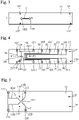
Fig. 4 is a plan view of a second-layer film and electrode wires thereon of the extracellular potential measurement device according to the embodiment; -
Fig. 5 is a plan view of a third-layer film and electrode wires thereon of the extracellular potential measurement device according to the embodiment; -
Fig. 6 is a plan view of a bottom-layer film and electrode wires thereon of the extracellular potential measurement device according to the embodiment; -
Fig. 7 is an enlarged perspective view of a part of the extracellular potential measurement device according to the embodiment; -
Fig. 8 is an enlarged plan view of a part of the extracellular potential measurement device according to the embodiment; -
Fig. 9 is a diagram showing a plurality of examples of samples of collections of cells to be disposed in the extracellular potential measurement device according to the embodiment; -
Fig. 10 is an enlarged plan view, similar toFig. 8 , of a part of the extracellular potential measurement device in which an example of a sample is disposed; -
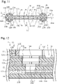
Fig. 11 is an enlarged plan view, similar toFig. 8 , of a part of an extracellular potential measurement device according to a modification of the embodiment of the present invention; and -
Fig. 12 is a cross-sectional view of an extracellular potential measurement device according to another modification of the embodiment of the present invention. - Hereinafter, with reference to the accompanying drawings, various embodiments according to the present invention will be described. It is of note that the drawings are not necessarily to scale, and certain features may be exaggerated or omitted.
- As shown in
Fig. 1 , an extracellular potential measurement device 1 includes a laminated structure having multipleelectric insulating films adhesive layers insulating films insulating films adhesive layer 11A, and theinsulating films adhesive layer 12A. Theinsulating films adhesive layer 13A. - The
insulating films adhesive layers sheet 10. Thesheet 10 has arecess 2, which will be described later, and agroove 3 connected to therecess 2. - The extracellular potential measurement device 1 further includes
multiple electrode wires sheet 10. Each electrode wire is placed between upper and lower insulating films. - As shown in
Figs. 1 and 2 , except for the bottom-layer insulation film 14, each of theinsulation films opening openings openings - The opening 13H in the
insulating film 13 has a diameter, i.e., a size that is less than that of the opening 12H in theinsulating film 12 immediately above it. The opening 12H in theinsulating film 12 has a diameter, i.e., a size that is less than that of the opening 11H in theinsulating film 11 immediately above it. When the multipleinsulating films openings recess 2 that has an almost cone-shape or bowl-shape with a varying size reducing downward. However, the shapes of theopenings - Each of the
adhesive layers adhesive layers - Each of the insulating
films adhesive layers films adhesive layers - Each of the
electrode wires electrode wires - An end of each of the multiple electrode wires are located near the openings in the insulating films immediately below the electrode wires and are exposed in the
recess 2. More specifically, ends ofelectrode wires opening 12H of the insulatingfilm 12 immediately below theelectrode wires upper opening 11H. Ends of theelectrode wires 13B are located near theopening 13H of the insulatingfilm 13 immediately below theelectrode wire 13B, and are exposed through theupper openings - An end of the
electrode wire 14B interposed between the bottom-layer insulation film 14 and the second-lowermost-layer insulation film 13 traverses the entirety of theopening 13H in the second-lowermost-layer insulating film 13 in one direction. More specifically, the end of theelectrode wire 14B extends along a diameter of thecircular opening 13H and traverses theopening 13H. The end of theelectrode wire 14B is exposed through theupper openings -
Figs. 3 to 6 are plan views of the insulatingfilms Fig. 1 corresponds to the cross-section taken along line I-I inFigs. 3 to 6 . - As shown in
Fig. 3 , the top-layer insulating film (cover film) 11 has theaforementioned opening 11H, anotheropening 21H having the same shape and the same size as those of theopening 11H, and a linear slit orgroove 3 connecting theopenings openings groove 3 penetrate the insulatingfilm 11. - In addition, multiple through-
holes 11P are formed in the insulatingfilm 11 for positioning the insulatingfilms - As shown in
Fig. 4 , the insulatingfilm 12 has theaforementioned opening 12H and anotheropening 22H having the same shape and the same size as those of theopenings 12H. Theopenings film 12. Theopening 22H is almost concentric to theopening 21H of the insulatingfilm 11. Theopening 22H in the insulatingfilm 12 has a diameter, i.e., a size that is less than that of theopening 21H in the insulatingfilm 11 immediately above it. Theopening 22H of insulatingfilm 12 has a diameter, or size, smaller than the diameter, or size, of the opening 2H of insulatingfilm 11 immediately above it. When the insulatingfilms openings - In the insulating
film 12, multiple through-holes 12P are formed for positioning the insulatingfilms - The
aforementioned electrode wires film 12.Wide connection terminals 12T and 12CT are formed at the ends of theelectrode wires opening 12H. - In addition, on the upper surface of the insulating
film 12, multipleaxon electrode wires 30, which will be described later, are formed. An end of each of the multiple axon electrode wires are located in the vicinity of a straight line connecting theopenings groove 3 of the insulatingfilm 11 immediately above.Wide connection terminals 30T are formed at the opposite ends of theaxon terminal wires 30. - Each of the
axon electrode wires 30 is formed from an electroconductive material with high conductivity that has as little effect as possible on cells. For example, theaxon electrode wires 30 are formed from gold-plated copper wires. - As shown in
Fig. 5 , theaforementioned opening 13H is formed in the insulatingfilm 13. Theopening 13H penetrates the insulatingfilm 13. - In addition, the insulating
film 13 has multiple through-holes 13P for positioning the insulatingfilms - On the upper surface of the insulating
film 13, theaforementioned electrode wires 13B are formed.Wide connection terminals 13T are formed at the ends of theelectrode wires 13B, which are opposite to the ends near theopening 13H. - As shown in
Fig. 6 , multiple through-holes 14P are formed in the insulatingfilm 14 for positioning the insulatingfilms - On the upper surface of the insulating
film 14, theaforementioned electrode wire 14 is formed. Awide connection terminal 14T is formed at the end of theelectrode wire 14B, which is opposite to the end overlapping theopening 13H. - The holes and grooves in the insulating films can be formed by, for example, etching. The electrode wires can be formed on the insulating films by, for example, photolithography.
- When joining insulating
films adhesive layers holes films - The insulating
film 11 and the insulatingfilms adhesive layers - As shown in
Fig. 2 , the width of the insulatingfilm 11 is less than that of the insulatingfilm 12 immediately below it, and almost all of theelectrode wires film 12 are covered with and protected by the upper insulatingfilm 11. However, theconnection terminals 12T, 12CT, and 30T of theelectrode wires film 12 is less than that of the insulatingfilm 13 immediately below it, and almost all of theelectrode wires 13B formed on the insulatingfilm 13 are covered with and protected by the upper insulatingfilm 12. However, theconnection terminals 13T of theelectrode wires 13B are exposed at least in part. The length of insulatingfilm 13 is less than that of the insulatingfilm 14 immediately below it, and almost all of theelectrode wire 14B formed on insulatingfilm 14 is covered with and protected by the upper insulatingfilm 13. However, theconnection terminal 14T of theelectrode wire 14B is exposed at least in part. - Accordingly, the
connection terminals 12T, 12CT, 30T, 13T, and 14T can be easily connected to a potential measurement device (not shown). - As shown in
Figs. 7 and 8 , the ends ofelectrode wires recess 2. An end of theelectrode wire 14B formed on the insulatingfilm 12 extends in thegroove 3 formed in the insulatingfilm 12. Theelectrode wire 14B is bent, and portions other than the end are covered by the insulatingfilm 14. -
Fig. 8 shows theaforementioned opening 21H formed in the insulatingfilm 11 and theaforementioned opening 22H formed in the insulatingfilm 12. When the insulatingfilms openings recess 4 that has an almost cone-shape or bowl-shape with a varying size reducing downward. However, the shapes of theopenings - The
openings groove 3 formed in the insulatingfilm 11. Ends of the multiple axon electrode wires formed on the insulatingfilm 12 immediately below thegroove 3 are exposed in thegroove 3 in the insulatingfilm 11. - To prevent the
groove 3 from being filled with theadhesive layer 11A, and to improve the dimensional accuracy of theopenings portion 11X around thegroove 3 and theopenings film 11 are preferably formed by photolithography. - More specifically, first the insulating
film 11 without theportion 11X (the insulatingfilm 11 having a penetrating recess corresponding to theportion 11X) is formed. The recess can be formed in the insulatingfilm 11 by, for example, etching. - Next, pins (not shown) are inserted into the through-
holes films films adhesive layers - Thereafter, the recess corresponding to the
portion 11X is filled with an ultra-violet-curable resin, and a portion of the UV-curable resin other than thegroove 3 and recesses 2 and 4 is exposed to an ultra-violet light to be cured. Furthermore, thegroove 3 and therecesses groove 3 and theopenings - The
portion 11X formed in this way reaches not only the layer of the insulatingfilm 11, but also theadhesive layer 11A as shown inFig. 1 . As shown inFig. 8 , ends of theaxon electrode wires 30 penetrate theportion 11X. - In this embodiment, a three-dimensional collection of cells is stored in the
recess 2 with a varying size reducing downward, which is provided by overlapping theopenings films electrode wires recess 2, so that ends of themultiple electrode wires multiple electrode wires - An end of the
lowest electrode wire 14B traverses the entirety of the opening of the second-lowermost-layer insulating film 13, i.e., the bottom of therecess 2, in one direction. Accordingly, a large area of the end of theelectrode wire 14B is exposed in therecess 2, and the collection of cells located in therecess 2 is likely to come into contact with the end of theelectrode wire 14B. Theelectrode wire 14B, which has a high probability of contacting a collection of cells, can be preferably used as a reference electrode, for example. However, the reference electrode may be any one of the other electrode wires. - In the extracellular potential measurement device 1 according to the embodiment, multiple insulating films insulating films having
openings openings recess 2 with a varying size reducing downward, which is suitable for storing a three-dimensional collection of cells, andelectrode wires films insulating films - The collection of cells disposed in the
recess 2 may be a cell mass in vivo or a cell mass, an organoid, or a spheroid cultured in vitro. -
Fig. 9 shows a plurality of examples of samples that may be used for extracellular potential measurement using the extracellular potential measurement device 1.Sample 40 is a collection of cells that do not have axons.Sample 41 is acollection 42 of cells related to neurons and anaxon 43 extending from thecollection 42 of cells.Sample 44 has twocollections axon 47 connected tocollections recess 2 of the extracellular potential measurement device 1, any ofsample 40, thecollection 42 of cells, and thecollection -
Fig. 10 shows measurement of potentials ofsample 44 as an example of measurement of potentials of samples. Thecollections recesses axon 47 is deployed in thegroove 3. - The bottom of the
collection 45 of cells is brought into contact with the end of theelectrode wire 14B at the bottom of therecess 2. Ends of theelectrode wires recess 2 can be in contact with thecollection 45 of cells, and as long as they are in contact with thecollection 45 of cells, the potential at each point of thecollection 45 of cells can be measured through theelectrode wires - In addition, ends of the
axon electrode wires 30 exposed in thegroove 3 can be in contact with theaxon 47 located in thegroove 3, and as long as they are in contact with theaxon 47, the potential at each point of theaxon 47 can be measured through theaxon electrode wires 30. In measuring potentials of the axon as well as measuring potentials of thecollection 45 of cells, for example, theelectrode wire 14B can be used as the reference electrode, but any one of the other electrode wires can also be used as a reference electrode. - According to the extracellular potential measurement device 1, in addition to potentials of a collection of cells, potentials of an axon extending from the collection of cells can be measured. By analyzing the potentials, it is possible to study in vitro models that are useful for estimating signal transduction in neurons in vivo, and to evaluate, for example, drug effects and/or side effects on neurons.
- Only one
axon electrode wire 30 may be provided. However, in this embodiment, multipleaxon electrode wires 30 are provided, and potentials at multiple points in the length direction of the axon can be measured, enabling more detailed analysis. -
Fig. 11 is an enlarged plan view, similar toFig. 8 , of a part of an extracellular potential measurement device according to a modification of the embodiment. In this modification, potentials of bothcollections sample 44 can be measured. - As shown in
Fig. 11 , this modification has a second recess 4A with electrodes instead of therecess 4 without electrodes. The second recess 4A is formed by anopening 21H that penetrates the insulatingfilm 11, anopening 22H that penetrates the insulatingfilm 12, and anopening 23H that penetrates the insulatingfilm 13. In the second recess 4A, acollection 46 of cells is disposed in order to measure potentials of thecollection 46 of cells. Theopenings - When the plurality of insulating
films second openings openings second opening 21H of the second recess 4A is connected to thegroove 3. - Therefore, in this modification, the
sheet 10 formed by the insulatingfilm adhesive layers recess 2, agroove 3 connected to therecess 2, and a second recess 4A connected to thegroove 3. - This modification further has multiple
second electrode wires sheet 10. Each electrode wire is interposed between upper and lower insulating films. Thesecond electrode wires collection 46 of cells. Each of the second electrode wires is formed from an electroconductive material with high conductivity that has as little effect as possible on cells. For example, the second electrode wires are formed from gold-plated copper wires. - An end of each of the second electrode wires are located near the second opening in the insulating film immediately below it and is exposed in the second recess 4A. More specifically, the
second electrode wires film 12, and ends of thesecond electrode wires opening 22H of the insulatingfilm 12 immediately below thesecond electrode wires upper opening 21H. Thesecond electrode wires 23B are formed on the insulatingfilm 13, and ends of thesecond electrode wires 23B are located near theopening 23H in the insulatingfilm 13 immediately below thesecond electrode wire 23B, and are exposed through theupper openings - The
second electrode wires 22B correspond to theelectrode wires 12B associated with therecess 2, and thesecond electrode wire 22C corresponds to theelectrode wire 12C associated with therecess 2. Thesecond electrode wires 23B correspond to theelectrode wires 23B associated with therecess 2. The details of thesecond electrode wires electrode wires - The
electrode wire 14B traverses the entirety of theopening 23H in the second-lowermost-layer insulating film 13 in one direction. More specifically, theelectrode wire 14B extends along a diameter of the circularsecond opening 23H and traverses thesecond opening 23H. Theelectrode wire 14B is exposed through the uppersecond openings collection 46 of cells as well as measuring potentials of thecollection 45 of cells, for example,electrode wire 14B can be used as a reference electrode, but any one of the other electrode wires can also be used as a reference electrode. - The bottom of the
collection 46 of cells is brought into contact with the end of theelectrode wire 14B at the bottom of the second recess 4A. Ends of thesecond electrode wires collection 46 of cells, and as long as they are in contact with thecollection 46 of cells, the potential at each point of thecollection 46 of cells can be measured through thesecond electrode wires - In this modification, a three-dimensional
second collection 46 of cells is stored in the second recess 4A with a varying size reducing downward, which is provided by overlapping thesecond openings films second electrode wires second electrode wires second electrode wires - Thus, potentials at multiple points of the two
collections axon 47 between them can be measured. By analyzing the potentials, it is possible to study models of neuronal signal transduction in vivo, and in particular, interaction between the two collections of cells. - Since this modification has multiple
second electrode wires axon electrode wires 30, is different fromFig. 2 (the second recess 4A is located at the position of therecess 4 inFig. 2 ). However, by devising the pattern of the electrode wires including the axon electrode wires and the second electrode wires, it is possible to arrange the second electrode wires as in the modification. -
Fig. 12 is a cross-sectional view of an extracellular potential measurement device according to another modification of the present invention. In this modification, ends of each of theelectrode wires openings films Fig. 1 , exposed portions of theelectrode wires recesses 2 are increased, which increases the probability of contact with the collection of cells. - The present invention has been shown and described with reference to preferred embodiments thereof. However, it will be understood by those skilled in the art that various changes in form and detail may be made without departing from the scope of the invention as defined by the claims. Such variations, alterations, and modifications are intended to be encompassed in the scope of the present invention.
- For example, the number of insulating films, the ratio of thicknesses of the multiple insulating films, the ratio of sizes of the multiple openings, the number, thickness, arrangement, and other details of the electrode wires including the axon electrode wires and the second electrode wires are not limited to the above-described embodiment and modifications.
- In addition to the
recess 2 and the second recess 4A shown inFig. 11 , more recesses and grooves connecting the recesses can be provided in an extracellular potential measurement device. Collection of cells and axons may be located in the recesses, respectively, and the potentials of these cells and axons may be measured. - Aspects of the present invention are also set out in the following numbered clauses:
- Clause 1. An extracellular potential measurement device including:
- multiple insulating films each of which is made from an electric insulating material, the insulating films being stacked and bonded to each other; and
- multiple electrode wires each of which is made from an electroconductive material, the electrode wires being arranged in multiple heights,
- each of the electrode wires being interposed between an upper insulating film and a lower insulating film,
- each of the insulating films, except for a lowermost insulating film, having an opening penetrating the insulating film,
- the opening in a lower insulating film having a size that is less than that of the opening in an upper insulating film, the openings in the insulating films being overlapped to form a recess having a size reducing downward, the recess being adapted to store a collection of cells,
- each of the electrode wires having an end that is located near an opening in an insulating film that is immediately below the electrode wire, the ends being exposed in the recess.
-
Clause 2. The extracellular potential measurement device according to clause 1, wherein an end of an electrode wire interposed between the lowermost insulating film and a second lowermost insulating film traverses the opening of the second lowermost insulating film entirely in one direction.
According to this clause, the end of this electrode wire traverses the entirety of the opening of the second lowermost insulating film, i.e., the bottom of the recess, in one direction. Accordingly, a large area of the end of the electrode wire is exposed in the recess, and the collection of cells located in the recess is likely to come into contact with the end of the electrode wire. The electrode wire, which has a high probability of contacting a collection of cells, can be preferably used as a reference electrode, for example. -
Clause 3. The extracellular potential measurement device according toclause 1 or 2, wherein an uppermost insulating film has a groove penetrating the uppermost insulating film, the groove being adapted to store a linear axon extending from the collection of cells, the groove being connected to the recess,
the extracellular potential measurement device further including at least one axon electrode wire, an end of the axon electrode wire is exposed in the groove so as to be brought into contact with the axon.
According to this clause, in addition to potentials of a collection of cells, potentials of an axon extending from the collection of cells can be measured. By analyzing the potentials, it is possible to study in vitro models that are useful for estimating signal transduction in neurons in vivo, and to evaluate, for example, drug effects and/or side effects on neurons. -
Clause 4. The extracellular potential measurement device according toclause 3, further including multiple second electrode wires each of which is made from an electroconductive material, the second electrode wires being arranged in multiple heights,- each of the second electrode wires being interposed between an upper insulating film and a lower insulating film,
- each of the insulating films, except for the lowermost insulating film, having a second opening penetrating the insulating film,
- the second opening in a lower insulating film having a size that is less than that of the second opening in an upper insulating film, the second openings in the insulating films being overlapped to form a second recess having a size reducing downward, the second recess being adapted to store a second collection of cells to which the axon is connected, the second recess being connected to the groove,
- each of the second electrode wires having an end that is located near a second opening in an insulating film that is immediately below the second electrode wire, the ends of the second electrode wires being exposed in the second recess.
- According to this clause, a three-dimensional second collection of cells is stored in the second recess with a varying size reducing downward, which is provided by overlapping the second openings of the multiple insulating films stacked. An end of each of the second electrode wires interposed between upper and lower insulating films is located near the second opening of the insulating film immediately below it and is exposed in the second recess, so that ends of the multiple second electrode wires can be in contact with the three-dimensional second collection of cells. The multiple second electrode wires are arranged in multiple heights, i.e., in multiple layers, so that electric potentials at multiple points in different heights of the second collection of cells can be measured. Thus, potentials at multiple points of the two collections of cells and the axon therebetween can be measured. By analyzing the potentials, it is possible to study models of neuronal signal transduction in vivo, and in particular, interaction between the two collections of cells.
- Clause 5. The extracellular potential measurement device according to any one of clauses 1 to 4, wherein the upper insulating film and the lower insulating film are bonded together with an adhesive.
- According to this clause, the extracellular potential measurement device can be easily manufactured.
- Clause 6. An extracellular potential measurement device including:
- a sheet including multiple insulating films each of which is made from an electric insulating material, the insulating films being stacked and bonded to each other, the sheet further including a recess adapted to store a collection of cells and a groove connected to the recess, the groove being adapted to store a linear axon extending from the collection of cells; and
- multiple electrode wires interposed between the insulating films of the sheet,
- multiple electrode wires having ends exposed in the recess so as to be brought into contact with the collection of cells,
- at least one electrode wire having an end exposed in the groove so as to be brought into contact with the axon.
- Clause 7. The extracellular potential measurement device according to clause 6, wherein the electrode wires that have ends exposed in the recess are arranged in multiple heights.
- According to this clause, electric potentials at multiple points in different heights of a three-dimensional collection of cells can be measured.
- Clause 8. The extracellular potential measurement device according to clause 7, wherein each of the insulating films, except for a lowermost insulating film, has an opening penetrating the insulating film,
- the opening in a lower insulating film having a size that is less than that of the opening in an upper insulating film, the openings in the insulating films being overlapped to form the recess having a size reducing downward,
- each of the electrode wires having an end that is located near an opening in an insulating film that is immediately below the electrode wire, the ends being exposed in the recess.
- According to this clause, a three-dimensional collection of cells is stored in the recess with a varying size reducing downward, which is provided by overlapping the openings of the multiple insulating films stacked. An end of each of the electrode wires interposed between upper and lower insulating films is located near the opening in the insulating film immediately below it and is exposed in the recess. Accordingly, ends of the multiple electrode wires can be in contact with at multiple points in different heights of the three-dimensional collection of cells.
- Clause 9. The extracellular potential measurement device according to any one of clauses 6 to 8, further including multiple second electrode wires interposed between the insulating films of the sheet,
- the sheet including a second recess adapted to store a second collection of cells to which the axon is connected, the second recess being connected to the groove,
- each of the second electrode wires having an end exposed in the second recess so as to be brought into contact with the second collection of cells.
- According to this clause, electric potentials at multiple points of the two collections of cells and the axon therebetween can be measured. By analyzing the potentials, it is possible to study in vitro models that are useful for estimating signal transduction in neurons in vivo, and in particular, interaction between the two collections of cells.
-
Clause 10. The extracellular potential measurement device according to clause 9, wherein the second electrode wires are arranged in multiple heights. - According to this clause, electric potentials at multiple points in different heights of a three-dimensional second collection of cells can be measured.
-
Clause 11. The extracellular potential measurement device according toclause 10, wherein each of the insulating films, except for the lowermost insulating film, has a second opening penetrating the insulating film, - the second opening in a lower insulating film having a size that is less than that of the second opening in an upper insulating film, the second openings in the insulating films being overlapped to form the second recess having a size reducing downward,
- each of the second electrode wires having an end that is located near a second opening in an insulating film that is immediately below the second electrode wire, the ends of the second electrode wires being exposed in the second recess.
- According to this clause, a three-dimensional second collection of cells is stored in the second recess with a varying size reducing downward, which is provided by overlapping the second openings of the multiple insulating films stacked. An end of each of the second electrode wires interposed between upper and lower insulating films is located near the second opening of the insulating film immediately below it and is exposed in the second recess, so that ends of the multiple second electrode wires can be easily in contact with multiple points in different heights of the three-dimensional second collection of cells.
-
- 1: Extracellular potential measurement device
- 2: Recess
- 3: Groove
- 4A: Second recess
- 10: Sheet
- 11, 12, 13, 14: Insulating film
- 11A, 12A, 13A: Adhesive layer
- 12B, 12C, 13B, 14B: Electrode wire
- 11H, 12H, 13H: Opening
- 21H, 22H, 23H: Second opening
- 30: Axon electrode wire
- 40: Sample
- 41: Sample
- 42: Collection of cells
- 43: Axon
- 44: Sample
- 45, 46: Collection of cells
- 47: Axon
- 22B, 22C, 23B: Second electrode wire
Claims (11)
- An extracellular potential measurement device comprising:multiple insulating films each of which is made from an electric insulating material, the insulating films being stacked and bonded to each other; andmultiple electrode wires each of which is made from an electroconductive material, the electrode wires being arranged in multiple heights,each of the electrode wires being interposed between an upper insulating film and a lower insulating film,each of the insulating films, except for a lowermost insulating film, having an opening penetrating the insulating film,the opening in a lower insulating film having a size that is less than that of the opening in an upper insulating film, the openings in the insulating films being overlapped to form a recess having a size reducing downward, the recess being adapted to store a collection of cells,each of the electrode wires having an end that is located near an opening in an insulating film that is immediately below the electrode wire, the ends being exposed in the recess.
- The extracellular potential measurement device according to claim 1, wherein an end of an electrode wire interposed between the lowermost insulating film and a second lowermost insulating film traverses the opening of the second lowermost insulating film entirely in one direction.
- The extracellular potential measurement device according to claim 1 or 2, wherein an uppermost insulating film has a groove penetrating the uppermost insulating film, the groove being adapted to store a linear axon extending from the collection of cells, the groove being connected to the recess,
the extracellular potential measurement device further comprising at least one axon electrode wire, an end of the axon electrode wire is exposed in the groove so as to be brought into contact with the axon. - The extracellular potential measurement device according to claim 3, further comprising multiple second electrode wires each of which is made from an electroconductive material, the second electrode wires being arranged in multiple heights,each of the second electrode wires being interposed between an upper insulating film and a lower insulating film,each of the insulating films, except for the lowermost insulating film, having a second opening penetrating the insulating film,the second opening in a lower insulating film having a size that is less than that of the second opening in an upper insulating film, the second openings in the insulating films being overlapped to form a second recess having a size reducing downward, the second recess being adapted to store a second collection of cells to which the axon is connected, the second recess being connected to the groove,each of the second electrode wires having an end that is located near a second opening in an insulating film that is immediately below the second electrode wire, the ends of the second electrode wires being exposed in the second recess.
- The extracellular potential measurement device according to any one of claims 1 to 4, wherein the upper insulating film and the lower insulating film are bonded together with an adhesive.
- An extracellular potential measurement device comprising:a sheet comprising multiple insulating films each of which is made from an electric insulating material, the insulating films being stacked and bonded to each other, the sheet further comprising a recess adapted to store a collection of cells and a groove connected to the recess, the groove being adapted to store a linear axon extending from the collection of cells; andmultiple electrode wires interposed between the insulating films of the sheet,multiple electrode wires having ends exposed in the recess so as to be brought into contact with the collection of cells,at least one electrode wire having an end exposed in the groove so as to be brought into contact with the axon.
- The extracellular potential measurement device according to claim 6, wherein the electrode wires that have ends exposed in the recess are arranged in multiple heights.
- The extracellular potential measurement device according to claim 7, wherein each of the insulating films, except for a lowermost insulating film, has an opening penetrating the insulating film,the opening in a lower insulating film having a size that is less than that of the opening in an upper insulating film, the openings in the insulating films being overlapped to form the recess having a size reducing downward,each of the electrode wires having an end that is located near an opening in an insulating film that is immediately below the electrode wire, the ends being exposed in the recess.
- The extracellular potential measurement device according to any one of claims 6 to 8, further comprising multiple second electrode wires interposed between the insulating films of the sheet,the sheet comprising a second recess adapted to store a second collection of cells to which the axon is connected, the second recess being connected to the groove,each of the second electrode wires having an end exposed in the second recess so as to be brought into contact with the second collection of cells.
- The extracellular potential measurement device according to claim 9, wherein the second electrode wires are arranged in multiple heights.
- The extracellular potential measurement device according to claim 10, wherein each of the insulating films, except for a lowermost insulating film, has a second opening penetrating the insulating film,the second opening in a lower insulating film having a size that is less than that of the second opening in an upper insulating film, the second openings in the insulating films being overlapped to form the second recess having a size reducing downward,each of the second electrode wires having an end that is located near a second opening in an insulating film that is immediately below the second electrode wire, the ends of the second electrode wires being exposed in the second recess.
Applications Claiming Priority (3)
| Application Number | Priority Date | Filing Date | Title |
|---|---|---|---|
| JP2019205943 | 2019-11-14 | ||
| JP2019205942 | 2019-11-14 | ||
| PCT/JP2020/037452 WO2021095393A1 (en) | 2019-11-14 | 2020-10-01 | Extracellular potential measurement device |
Publications (2)
| Publication Number | Publication Date |
|---|---|
| EP4060018A1 true EP4060018A1 (en) | 2022-09-21 |
| EP4060018A4 EP4060018A4 (en) | 2023-03-01 |
Family
ID=75912635
Family Applications (1)
| Application Number | Title | Priority Date | Filing Date |
|---|---|---|---|
| EP20886240.9A Withdrawn EP4060018A4 (en) | 2019-11-14 | 2020-10-01 | DEVICE FOR MEASURING EXTRACELLULAR POTENTIAL |
Country Status (5)
| Country | Link |
|---|---|
| US (1) | US11946847B2 (en) |
| EP (1) | EP4060018A4 (en) |
| JP (1) | JP7231168B2 (en) |
| CN (1) | CN114729909A (en) |
| WO (1) | WO2021095393A1 (en) |
Families Citing this family (1)
| Publication number | Priority date | Publication date | Assignee | Title |
|---|---|---|---|---|
| CN114729909A (en) * | 2019-11-14 | 2022-07-08 | Nok株式会社 | Extracellular potential measuring device |
Family Cites Families (25)
| Publication number | Priority date | Publication date | Assignee | Title |
|---|---|---|---|---|
| WO1999019717A1 (en) | 1997-10-15 | 1999-04-22 | Aclara Biosciences, Inc. | Laminate microstructure device and method for making same |
| JPH11187865A (en) * | 1997-12-25 | 1999-07-13 | Matsushita Electric Ind Co Ltd | Cell potential measuring electrode and measuring device using the same |
| US6132683A (en) | 1998-12-23 | 2000-10-17 | Matsushita Electric Industrial Co., Ltd. | Cell potential measuring electrode and measuring apparatus using the same |
| JP2004534226A (en) * | 2001-06-29 | 2004-11-11 | メソ スケイル テクノロジーズ,エルエルシー | Assay plate, reader system and method for luminescence test measurement |
| JP4747852B2 (en) * | 2006-01-23 | 2011-08-17 | パナソニック株式会社 | Cell electrophysiological sensor and manufacturing method thereof |
| WO2009013876A1 (en) * | 2007-07-20 | 2009-01-29 | Panasonic Corporation | Electrode plate for electrochemical measurement, electrochemical measuring apparatus having the electrode plate, and method for determining target substance by using the electrode plate |
| JP5528111B2 (en) | 2007-09-18 | 2014-06-25 | バイオテック株式会社 | Cell measurement container, extracellular potential measurement method, drug inspection method |
| GB0800797D0 (en) | 2008-01-16 | 2008-02-27 | Cambridge Entpr Ltd | Neural interface |
| CN101919043B (en) * | 2008-01-21 | 2013-06-05 | 金振有限公司 | Display device |
| WO2011010721A1 (en) | 2009-07-24 | 2011-01-27 | ニプロ株式会社 | Container for measuring cell potential and method for producing same |
| JP2011096780A (en) * | 2009-10-28 | 2011-05-12 | Elpida Memory Inc | Semiconductor device and method of manufacturing the same |
| CN201532352U (en) * | 2009-11-06 | 2010-07-21 | 东南大学 | Micro-Nano Single Particle Impedance Spectroscopy Chip |
| KR101136534B1 (en) * | 2010-09-07 | 2012-04-17 | 한국기계연구원 | Probe card and manufacturing method thereof |
| US9447447B2 (en) | 2010-09-30 | 2016-09-20 | National University Corporation Tokyo Medical And Dental University | Method and apparatus for testing cardiotoxicity and evaluating cardiomyocytes |
| US9891157B2 (en) | 2010-12-03 | 2018-02-13 | Cellply S.R.L. | Microanalysis of cellular function |
| KR20130020402A (en) * | 2011-08-19 | 2013-02-27 | 건국대학교 산학협력단 | Biochip using the insulated membrane of metal oxide |
| JP6393930B2 (en) * | 2012-01-30 | 2018-09-26 | 俊 保坂 | Semiconductor sensor device and manufacturing method thereof |
| DK2899262T3 (en) | 2012-09-19 | 2017-10-02 | Japan Science & Tech Agency | CREATION AND USE OF NEURON NETWORKS AND NEURO EDUCATION DEVICES |
| US9915599B2 (en) * | 2013-02-08 | 2018-03-13 | Sony Corporation | Microparticle analysis apparatus and microparticle analysis system |
| JP6550694B2 (en) * | 2014-07-08 | 2019-07-31 | 国立大学法人九州工業大学 | Extracellular potential measuring device and extracellular potential measuring method |
| JP6382699B2 (en) * | 2014-11-28 | 2018-08-29 | 株式会社東芝 | Micro analysis chip |
| US10556234B2 (en) * | 2015-10-06 | 2020-02-11 | Mohammad Abdolahad | Isolation and detection of circulating tumor cells (CTCs) |
| US10634635B2 (en) * | 2016-03-09 | 2020-04-28 | National Institute Of Advanced Industrial Science And Technology | Dielectric constant microscope and method of observing organic specimen |
| WO2017157874A1 (en) * | 2016-03-18 | 2017-09-21 | Universität Hamburg Arbeitsstelle Für Wissens- Und Technologietransfer | Photovoltaic device for stimulation of cells and/or electrochemical reactions |
| CN114729909A (en) * | 2019-11-14 | 2022-07-08 | Nok株式会社 | Extracellular potential measuring device |
-
2020
- 2020-10-01 CN CN202080078982.XA patent/CN114729909A/en active Pending
- 2020-10-01 EP EP20886240.9A patent/EP4060018A4/en not_active Withdrawn
- 2020-10-01 JP JP2021555941A patent/JP7231168B2/en active Active
- 2020-10-01 US US17/772,219 patent/US11946847B2/en active Active
- 2020-10-01 WO PCT/JP2020/037452 patent/WO2021095393A1/en not_active Ceased
Also Published As
| Publication number | Publication date |
|---|---|
| CN114729909A (en) | 2022-07-08 |
| US11946847B2 (en) | 2024-04-02 |
| EP4060018A4 (en) | 2023-03-01 |
| JP7231168B2 (en) | 2023-03-01 |
| US20220397511A1 (en) | 2022-12-15 |
| WO2021095393A1 (en) | 2021-05-20 |
| JPWO2021095393A1 (en) | 2021-05-20 |
Similar Documents
| Publication | Publication Date | Title |
|---|---|---|
| CN103140921B (en) | Exploration card and manufacture method thereof | |
| US9833385B2 (en) | Device for detecting the removal of drugs | |
| JP5823291B2 (en) | Cell potential measuring container | |
| TW200420885A (en) | Needle assembly of probe card | |
| TWI339266B (en) | ||
| US11946847B2 (en) | Extracellular potential measurement device | |
| US7946050B2 (en) | Three-dimensional microprobe array | |
| CN112198346B (en) | Probe head and conductive probe of probe head | |
| US20160224811A1 (en) | Wiring board and method for recognizing code information thereof | |
| KR20120055704A (en) | Non-contact communication medium | |
| CN110068711A (en) | Probe card device and rectangular probe | |
| CN107449349A (en) | Printed circuit board (PCB) | |
| TW201915493A (en) | Probe card device and round probe | |
| US20170074821A1 (en) | Electrochemical measurement device | |
| JPWO2021095393A5 (en) | ||
| TWI630393B (en) | Probe card device and rectangular probe thereof | |
| JPWO2011010721A1 (en) | Cell potential measuring container and manufacturing method thereof | |
| CN111090033A (en) | Semiconductor device and probe test method thereof | |
| CN118731131A (en) | Electrode circuit board for blood gas biochemistry measurement and method for making electrode | |
| CN103728345A (en) | Manufacturing method and structure of test piece for measuring biological fluid | |
| KR20140015237A (en) | Determining layer thickness | |
| TWI377350B (en) | Branched probe and method for making the same | |
| US10396333B2 (en) | Flexible electrochemical device pack | |
| CN211652658U (en) | A micro-supercapacitive sensor chip for blood physical and chemical index detection and its sensor | |
| CN115727998A (en) | A kind of graphene flexible electrode and preparation method thereof |
Legal Events
| Date | Code | Title | Description |
|---|---|---|---|
| STAA | Information on the status of an ep patent application or granted ep patent |
Free format text: STATUS: THE INTERNATIONAL PUBLICATION HAS BEEN MADE |
|
| PUAI | Public reference made under article 153(3) epc to a published international application that has entered the european phase |
Free format text: ORIGINAL CODE: 0009012 |
|
| STAA | Information on the status of an ep patent application or granted ep patent |
Free format text: STATUS: REQUEST FOR EXAMINATION WAS MADE |
|
| 17P | Request for examination filed |
Effective date: 20220426 |
|
| AK | Designated contracting states |
Kind code of ref document: A1 Designated state(s): AL AT BE BG CH CY CZ DE DK EE ES FI FR GB GR HR HU IE IS IT LI LT LU LV MC MK MT NL NO PL PT RO RS SE SI SK SM TR |
|
| DAV | Request for validation of the european patent (deleted) | ||
| DAX | Request for extension of the european patent (deleted) | ||
| A4 | Supplementary search report drawn up and despatched |
Effective date: 20230126 |
|
| RIC1 | Information provided on ipc code assigned before grant |
Ipc: B01L 3/00 20060101ALI20230123BHEP Ipc: G01N 27/00 20060101ALI20230123BHEP Ipc: C12M 1/34 20060101AFI20230123BHEP |
|
| STAA | Information on the status of an ep patent application or granted ep patent |
Free format text: STATUS: THE APPLICATION HAS BEEN WITHDRAWN |
|
| 18W | Application withdrawn |
Effective date: 20230724 |