EP4060008B1 - Rapid heating device and heating method for organic solid waste - Google Patents
Rapid heating device and heating method for organic solid waste Download PDFInfo
- Publication number
- EP4060008B1 EP4060008B1 EP22160004.2A EP22160004A EP4060008B1 EP 4060008 B1 EP4060008 B1 EP 4060008B1 EP 22160004 A EP22160004 A EP 22160004A EP 4060008 B1 EP4060008 B1 EP 4060008B1
- Authority
- EP
- European Patent Office
- Prior art keywords
- pyrolysis
- furnace
- pyrolysis furnace
- heating
- temperature
- Prior art date
- Legal status (The legal status is an assumption and is not a legal conclusion. Google has not performed a legal analysis and makes no representation as to the accuracy of the status listed.)
- Active
Links
Images
Classifications
-
- C—CHEMISTRY; METALLURGY
- C10—PETROLEUM, GAS OR COKE INDUSTRIES; TECHNICAL GASES CONTAINING CARBON MONOXIDE; FUELS; LUBRICANTS; PEAT
- C10B—DESTRUCTIVE DISTILLATION OF CARBONACEOUS MATERIALS FOR PRODUCTION OF GAS, COKE, TAR, OR SIMILAR MATERIALS
- C10B19/00—Heating of coke ovens by electrical means
-
- C—CHEMISTRY; METALLURGY
- C10—PETROLEUM, GAS OR COKE INDUSTRIES; TECHNICAL GASES CONTAINING CARBON MONOXIDE; FUELS; LUBRICANTS; PEAT
- C10B—DESTRUCTIVE DISTILLATION OF CARBONACEOUS MATERIALS FOR PRODUCTION OF GAS, COKE, TAR, OR SIMILAR MATERIALS
- C10B47/00—Destructive distillation of solid carbonaceous materials with indirect heating, e.g. by external combustion
-
- C—CHEMISTRY; METALLURGY
- C10—PETROLEUM, GAS OR COKE INDUSTRIES; TECHNICAL GASES CONTAINING CARBON MONOXIDE; FUELS; LUBRICANTS; PEAT
- C10B—DESTRUCTIVE DISTILLATION OF CARBONACEOUS MATERIALS FOR PRODUCTION OF GAS, COKE, TAR, OR SIMILAR MATERIALS
- C10B1/00—Retorts
- C10B1/02—Stationary retorts
- C10B1/04—Vertical retorts
-
- C—CHEMISTRY; METALLURGY
- C10—PETROLEUM, GAS OR COKE INDUSTRIES; TECHNICAL GASES CONTAINING CARBON MONOXIDE; FUELS; LUBRICANTS; PEAT
- C10B—DESTRUCTIVE DISTILLATION OF CARBONACEOUS MATERIALS FOR PRODUCTION OF GAS, COKE, TAR, OR SIMILAR MATERIALS
- C10B53/00—Destructive distillation, specially adapted for particular solid raw materials or solid raw materials in special form
-
- C—CHEMISTRY; METALLURGY
- C10—PETROLEUM, GAS OR COKE INDUSTRIES; TECHNICAL GASES CONTAINING CARBON MONOXIDE; FUELS; LUBRICANTS; PEAT
- C10B—DESTRUCTIVE DISTILLATION OF CARBONACEOUS MATERIALS FOR PRODUCTION OF GAS, COKE, TAR, OR SIMILAR MATERIALS
- C10B57/00—Other carbonising or coking processes; Features of destructive distillation processes in general
- C10B57/16—Features of high-temperature carbonising processes
Definitions
- the invention belongs to the technical field of energy and resource utilization of organic solid waste, and specifically relates to a device for rapid heating and high-efficiency heat preservation of organic solid waste.
- the invention also relates to a rapid heating method using the device.
- the organic solid waste production all over the world is large, with an annual output of 5 billion tons in China, but the reduction and resource utilization rate is low, which seriously affects the urban living environment.
- Pyrolysis technology can realize the reduction and resource utilization of organic solid waste, it can convert biomass energy into resource products such as fuel gas, bio-oil, and biochar. With the construction of Zero-waste City, organic solid waste pyrolysis technology has attracted more and more attention.
- the research on pyrolysis technology mainly focuses on the optimization of pyrolysis system, exhaust gas emission standards, etc.
- the existing organic solid waste pyrolysis technology and equipment have the disadvantages of long heating time, long start-up time, and low heat energy conversion efficiency.
- US 2012/073197 A1 discloses a gasifier including a combustion chamber and a pressure vessel surrounding the combustion chamber, wherein the pressure vessel includes an inner surface.
- a controller adjusts a pressure inside the pressure vessel so that a dew point temperature of corrosive compounds produced in the combustion chamber is less than a temperature of the inner surface of the pressure vessel.
- WO 03/040619 A1 discloses a carbonizing apparatus using a far infrared rays heater that can extremely heighten an operation efficiency by shortening a temperature rise time necessary for a carbonizing operation through a direct heating method using a cartridge heater of far infrared rays, and thus by preventing an unnecessary loss of power.
- the carbonizing apparatus includes a body case that has a door on one side face thereof, and has a far infrared rays heater and a carbonizing receptacle thereinside; the inner side wall faces of the body case are constructed of insulation bricks.
- JP 2002-129165 A discloses a carbonization tank comprising electric heaters which are arranged on the exterior of a far infrared ray radiating type ceramic layer formed in the inner wall of said tank.
- the ceramic layer is formed by coating a ceramic paint having far infrared ray radiation properties.
- the purpose of the present invention is to solve at least one of the technical problems existing in the prior art, and to provide a device for rapid heating and high-efficiency heat preservation of organic solid waste as defined in claim 1.
- Another object of the present invention is to provide a rapid heating method as defined in claim 6 using the above-mentioned device.
- the present invention provides a device as defined in claim 1 for rapid heating and efficient heat preservation of organic solid waste, including an infrared heater, a heating furnace, a pyrolysis furnace and an automatic control unit.
- the pyrolysis furnace is embedded in the heating furnace, the infrared heater is located on the outer side wall of the heating furnace, the outer wall of the pyrolysis furnace is coated with infrared absorbing paint, and the inner wall is covered with an insulating layer.
- the heating furnace and the pyrolysis furnace have uniform shapes, which can be oval, circular, rectangular or other shapes, preferably cylindrical, to ensure uniform heating.
- the infrared heater is uniformly arranged on the outer wall of the heating furnace for heating the pyrolysis furnace, and the heating rate is in the range of 75-125°C/s, preferably 90 ⁇ 110°C/s, most preferably 100°C/s. More than one infrared heaters can be set as required, and the wavelengths of the infrared rays emitted by the infrared heaters are all different.
- the outer wall of the pyrolysis furnace is uniformly coated with the infrared absorbing paint, and the inner wall is covered with the insulating layer.
- the infrared absorbing paint is semiconductor titanium oxide
- the material of the insulation layer on the inner wall of the pyrolysis furnace is ceramic fiber.
- the material of the pyrolysis furnace is silicon carbide and other materials with high temperature resistance and small specific heat capacity.
- the invention provides a method for rapid heating using the above-mentioned device, including the following steps: According to the type and feed amount of organic solid waste, the rapid heating of the pyrolysis furnace is realized, and the pyrolysis temperature of the pyrolysis furnace is maintained, so as to realize the high-efficiency pyrolysis of the organic solid waste.
- the heating rate of the pyrolysis heating device is controlled by the automatic control unit, and the automatic control unit performs automatic control according to the feed amount of the material and the pyrolysis temperature.
- the temperature of the pyrolysis furnace can rise to 1000°C within 1 minute, which greatly reduces the start-up time of the equipment.
- the infrared heater is turned off and the insulation layer is used to maintain the pyrolysis temperature in the pyrolysis furnace.
- the infrared heater is turned on again to realize the rapid heating of the pyrolysis furnace.
- the present invention has the following beneficial effects:
- a fast heating and efficient insulation device for organic solid waste was designed.
- the heat radiation of the infrared heater of the heating furnace realizes the rapid heating of the pyrolysis furnace, the pyrolysis furnace uses the insulation layer on the inner wall to prevent heat loss and maintain the pyrolysis temperature of the material, thereby realizing the rapid heating and efficient insulation of the material, and shortening the pyrolysis heating time, improving the pyrolysis efficiency of organic solid waste and effectively reduce the production of dioxin.
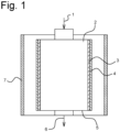
- Fig. 1 is a schematic diagram of the component structure of the organic solid waste rapid heating device of the present invention.
- Fig. 1 is a schematic diagram of a device for rapid heating and high-efficiency heat preservation of organic solid waste according to an embodiment of the present invention.
- the device of the present invention includes: an infrared heater 7, a heating furnace 5, a pyrolysis furnace 2 and an automatic control unit.
- the pyrolysis furnace 2 is embedded in the heating furnace 5, both ends of the pyrolysis furnace 2 are provided with a feed port 1 and a discharge port 6 respectively, and the infrared heater 7 is located on the outer side wall of the heating furnace 5, the outer wall of the pyrolysis furnace 2 is coated with infrared absorbing paint 4, and the inner wall is covered with an insulating layer 3.
- the number of infrared heaters can be one or more, preferably three.
- the pyrolysis furnace and the heating furnace can be elliptical, circular, rectangular or other uniform shapes, and preferably circular, with a temperature probe provided on the inner wall.
- the wave-absorbing paint coated on the outer wall of the pyrolysis furnace is semiconductor titanium oxide, and the inner wall insulation layer is made of ceramic fiber.
- the material of the pyrolysis furnace is materials with high temperature resistance and small specific heat capacity, such as silicon carbide.
- the pyrolysis furnace is nested in the heating furnace, and the solid waste processing capacity of the pyrolysis furnace is 0.1-2 tons/day. According to the processing needs, select the number of working infrared heaters. Turn on the infrared heater to heat the pyrolysis furnace. Under the action of the infrared absorbing material on the outer wall of the pyrolysis furnace, the temperature of the pyrolysis furnace rises to 1000°C within 10s. At this time, the feed port is opened, and the solid waste is rapidly pyrolyzed in the pyrolysis furnace, shortening the heating process and reducing the generation of dioxins. The pyrolysis furnace maintains the pyrolysis temperature above 900°C under the action of the insulation layer, and the solid waste after pyrolysis is discharged from the discharge port.
- the pyrolysis furnace is controlled by an automatic control unit, which is connected with a temperature probe of the pyrolysis furnace (known technology), and the use time of the infrared heater is controlled by analyzing the temperature in the furnace.
- the infrared heater is turned on for heating, and when the temperature is higher than 1000°C, the infrared heater is turned off to maintain the temperature in the pyrolysis furnace continuously above 850°C.
- the dioxin outlet content is below 0.05ngTEQ/Nm3, which meets the EU waste incineration pollutant emission standard (DIRECTIVE 2010).
- the dioxin content is 1.0ngTEQ/Nm3, The concentration of dioxins treated by the device of the invention is reduced by more than 95%.
Landscapes
- Chemical & Material Sciences (AREA)
- Engineering & Computer Science (AREA)
- Oil, Petroleum & Natural Gas (AREA)
- Materials Engineering (AREA)
- Organic Chemistry (AREA)
- Combustion & Propulsion (AREA)
- Processing Of Solid Wastes (AREA)
Description
- The invention belongs to the technical field of energy and resource utilization of organic solid waste, and specifically relates to a device for rapid heating and high-efficiency heat preservation of organic solid waste.
- The invention also relates to a rapid heating method using the device.
- The organic solid waste production all over the world is large, with an annual output of 5 billion tons in China, but the reduction and resource utilization rate is low, which seriously affects the urban living environment. Pyrolysis technology can realize the reduction and resource utilization of organic solid waste, it can convert biomass energy into resource products such as fuel gas, bio-oil, and biochar. With the construction of Zero-waste City, organic solid waste pyrolysis technology has attracted more and more attention. At present, the research on pyrolysis technology mainly focuses on the optimization of pyrolysis system, exhaust gas emission standards, etc. The existing organic solid waste pyrolysis technology and equipment have the disadvantages of long heating time, long start-up time, and low heat energy conversion efficiency. And the slow heating speed leads to the generation of dioxins in the pyrolysis process, which increases the back-end disposal cost and greatly limits the promotion of organic solid waste pyrolysis technology. There is an urgent need to design a rapid heating method for pyrolysis equipment, improve the heat energy conversion efficiency of pyrolysis equipment, and effectively suppress the production of dioxins.
-
US 2012/073197 A1 discloses a gasifier including a combustion chamber and a pressure vessel surrounding the combustion chamber, wherein the pressure vessel includes an inner surface. A controller adjusts a pressure inside the pressure vessel so that a dew point temperature of corrosive compounds produced in the combustion chamber is less than a temperature of the inner surface of the pressure vessel. -
WO 03/040619 A1 -
JP 2002-129165 A - The purpose of the present invention is to solve at least one of the technical problems existing in the prior art, and to provide a device for rapid heating and high-efficiency heat preservation of organic solid waste as defined in
claim 1. - Another object of the present invention is to provide a rapid heating method as defined in
claim 6 using the above-mentioned device. - To achieve the above purposes, the present invention provides a device as defined in
claim 1 for rapid heating and efficient heat preservation of organic solid waste, including an infrared heater, a heating furnace, a pyrolysis furnace and an automatic control unit. - The pyrolysis furnace is embedded in the heating furnace, the infrared heater is located on the outer side wall of the heating furnace, the outer wall of the pyrolysis furnace is coated with infrared absorbing paint, and the inner wall is covered with an insulating layer.
- In the described device, the heating furnace and the pyrolysis furnace have uniform shapes, which can be oval, circular, rectangular or other shapes, preferably cylindrical, to ensure uniform heating. In the described device, the infrared heater is uniformly arranged on the outer wall of the heating furnace for heating the pyrolysis furnace, and the heating rate is in the range of 75-125°C/s,
preferably 90~110°C/s, most preferably 100°C/s. More than one infrared heaters can be set as required, and the wavelengths of the infrared rays emitted by the infrared heaters are all different. In the described device, the outer wall of the pyrolysis furnace is uniformly coated with the infrared absorbing paint, and the inner wall is covered with the insulating layer. - In the described device, the infrared absorbing paint is semiconductor titanium oxide, and the material of the insulation layer on the inner wall of the pyrolysis furnace is ceramic fiber.
- In the described device, the material of the pyrolysis furnace is silicon carbide and other materials with high temperature resistance and small specific heat capacity.
- The invention provides a method for rapid heating using the above-mentioned device, including the following steps:
According to the type and feed amount of organic solid waste, the rapid heating of the pyrolysis furnace is realized, and the pyrolysis temperature of the pyrolysis furnace is maintained, so as to realize the high-efficiency pyrolysis of the organic solid waste. - In the described method, the heating rate of the pyrolysis heating device is controlled by the automatic control unit, and the automatic control unit performs automatic control according to the feed amount of the material and the pyrolysis temperature. When the device is started, the temperature of the pyrolysis furnace can rise to 1000°C within 1 minute, which greatly reduces the start-up time of the equipment. When the temperature is higher than 1000°C, the infrared heater is turned off and the insulation layer is used to maintain the pyrolysis temperature in the pyrolysis furnace. When the pyrolysis temperature in the pyrolysis furnace is lower than 900°C, the infrared heater is turned on again to realize the rapid heating of the pyrolysis furnace.
- Based on the above technical solutions, it can be known that the present invention has the following beneficial effects:
In view of the disadvantages of the pyrolysis technology and equipment of organic solid waste, such as long start-up time and low heat energy conversion efficiency, which lead to the generation of dioxins in the pyrolysis process and increase the back-end disposal cost, a fast heating and efficient insulation device for organic solid waste was designed. The heat radiation of the infrared heater of the heating furnace realizes the rapid heating of the pyrolysis furnace, the pyrolysis furnace uses the insulation layer on the inner wall to prevent heat loss and maintain the pyrolysis temperature of the material, thereby realizing the rapid heating and efficient insulation of the material, and shortening the pyrolysis heating time, improving the pyrolysis efficiency of organic solid waste and effectively reduce the production of dioxin. -
Fig. 1 is a schematic diagram of the component structure of the organic solid waste rapid heating device of the present invention. - Description of the logo in the figure
1 feed port, 2 pyrolysis furnace, 3 insulation layer, 4 paint, 5 heating furnace, 6 discharge port, 7 infrared heater. - In order to make the objectives, technical solutions and advantages of the present invention clearer, the present invention will be further described in detail below in conjunction with specific embodiments and with reference to the accompanying drawings.
- A specific implementation of the present invention will be described in detail below with reference to the accompanying drawings.
-
Fig. 1 is a schematic diagram of a device for rapid heating and high-efficiency heat preservation of organic solid waste according to an embodiment of the present invention. The device of the present invention includes: an infrared heater 7, aheating furnace 5, apyrolysis furnace 2 and an automatic control unit. - Specifically, in the device of the present invention, the
pyrolysis furnace 2 is embedded in theheating furnace 5, both ends of thepyrolysis furnace 2 are provided with afeed port 1 and adischarge port 6 respectively, and the infrared heater 7 is located on the outer side wall of theheating furnace 5, the outer wall of thepyrolysis furnace 2 is coated with infrared absorbingpaint 4, and the inner wall is covered with aninsulating layer 3. - In a specific embodiment, the number of infrared heaters can be one or more, preferably three. Wherein, the pyrolysis furnace and the heating furnace can be elliptical, circular, rectangular or other uniform shapes, and preferably circular, with a temperature probe provided on the inner wall. Wherein, the wave-absorbing paint coated on the outer wall of the pyrolysis furnace is semiconductor titanium oxide, and the inner wall insulation layer is made of ceramic fiber.
- Wherein, the material of the pyrolysis furnace is materials with high temperature resistance and small specific heat capacity, such as silicon carbide.
- Wherein, the pyrolysis furnace is nested in the heating furnace, and the solid waste processing capacity of the pyrolysis furnace is 0.1-2 tons/day. According to the processing needs, select the number of working infrared heaters. Turn on the infrared heater to heat the pyrolysis furnace. Under the action of the infrared absorbing material on the outer wall of the pyrolysis furnace, the temperature of the pyrolysis furnace rises to 1000°C within 10s. At this time, the feed port is opened, and the solid waste is rapidly pyrolyzed in the pyrolysis furnace, shortening the heating process and reducing the generation of dioxins. The pyrolysis furnace maintains the pyrolysis temperature above 900°C under the action of the insulation layer, and the solid waste after pyrolysis is discharged from the discharge port.
- Wherein, the pyrolysis furnace is controlled by an automatic control unit, which is connected with a temperature probe of the pyrolysis furnace (known technology), and the use time of the infrared heater is controlled by analyzing the temperature in the furnace. In the control process, when the temperature in the pyrolysis furnace is lower than 850°C, the infrared heater is turned on for heating, and when the temperature is higher than 1000°C, the infrared heater is turned off to maintain the temperature in the pyrolysis furnace continuously above 850°C.
- After testing, the dioxin outlet content is below 0.05ngTEQ/Nm3, which meets the EU waste incineration pollutant emission standard (DIRECTIVE 2010). Compared with the existing domestic organic solid waste pyrolysis incinerator, the dioxin content is 1.0ngTEQ/Nm3, The concentration of dioxins treated by the device of the invention is reduced by more than 95%.
- The specific embodiments described above further describe the objectives, technical solutions and beneficial effects of the present invention in detail. It should be understood that the above are only specific embodiments of the present invention and are not intended to limit the present invention as defined by the appended claims.
Claims (7)
- A rapid heating device for pyrolysis of organic solid waste, includes an infrared heater, a heating furnace, a pyrolysis furnace and an automatic control unit; the pyrolysis furnace is embedded in the heating furnace, the infrared heater is uniformly arranged on the outer side wall of the heating furnace, the outer wall of the pyrolysis furnace is uniformly coated with infrared absorbing paint for absorbing infrared wavelengths of heat radiation from the infrared heater, wherein under the action of the infrared absorbing paint, rapid heating of the pyrolysis furnace is realized, and the inner wall of the pyrolysis furnace is covered with an insulating layer, wherein the automatic control unit is configured to control the heating rate of the pyrolysis furnace according to pyrolysis temperature, wherein when the pyrolysis temperature in the pyrolysis furnace is lower than a first preset temperature, the automatic control unit turns on the infrared heater to realize the rapid heating of the pyrolysis furnace, and when the pyrolysis temperature is higher than a second preset temperature, the automatic control unit turns off the infrared heater to maintain the pyrolysis temperature in the pyrolysis furnace by relying on the insulating layer, wherein the heating rate of the rapid heating device is in the range of 75~125°C/s, preferably 90~110°C/s, most preferably 100°C/s.
- The device according to claim 1, wherein the heating furnace and the pyrolysis furnace have uniform shapes, such as oval, circular, rectangular or other shapes, to ensure uniform heating.
- The device according to claim 1, wherein the infrared heaters are uniformly arranged on the outer wall of the heating furnace, and multiple infrared heaters can be set as required, and the wavelengths of the infrared rays emitted by the infrared heaters are all different.
- The device according to claim 1, wherein the infrared absorbing paint coated on the outer wall of the pyrolysis furnace is semiconductor titanium oxide, and the material of the insulation layer on the inner wall of the pyrolysis furnace is ceramic fiber.
- The device according to claim 1, wherein the material of the pyrolysis furnace is silicon carbide.
- A rapid heating method using the device according to any one of claims 1 to 5, comprising the following steps:
The heating rate of the pyrolysis furnace is controlled by the automatic control unit, which automatically controls according to feed amount of materials and pyrolysis temperature, when the pyrolysis temperature in the pyrolysis furnace is lower than a first preset temperature, the infrared heater is turned on to realize the rapid heating of the pyrolysis furnace, when the pyrolysis temperature is higher than a second preset temperature, the infrared heater is turned off to maintain the pyrolysis temperature in the pyrolysis furnace by relying on the insulation layer. - The rapid heating method according to claim 6, wherein the infrared heater is turned on when the pyrolysis temperature in the pyrolysis furnace is lower than 900°C, and the infrared heater is turned off when the temperature is higher than 1000°C.
Applications Claiming Priority (1)
| Application Number | Priority Date | Filing Date | Title |
|---|---|---|---|
| CN202110233737.8A CN113025353B (en) | 2021-03-03 | 2021-03-03 | Organic solid waste rapid heating device and heating method |
Publications (2)
| Publication Number | Publication Date |
|---|---|
| EP4060008A1 EP4060008A1 (en) | 2022-09-21 |
| EP4060008B1 true EP4060008B1 (en) | 2024-05-08 |
Family
ID=76465628
Family Applications (1)
| Application Number | Title | Priority Date | Filing Date |
|---|---|---|---|
| EP22160004.2A Active EP4060008B1 (en) | 2021-03-03 | 2022-03-03 | Rapid heating device and heating method for organic solid waste |
Country Status (2)
| Country | Link |
|---|---|
| EP (1) | EP4060008B1 (en) |
| CN (1) | CN113025353B (en) |
Families Citing this family (1)
| Publication number | Priority date | Publication date | Assignee | Title |
|---|---|---|---|---|
| CN116351849A (en) * | 2023-03-14 | 2023-06-30 | 南京工大环境科技有限公司 | A method and device for non-catalytic thermochemical treatment of chemical waste salt |
Family Cites Families (6)
| Publication number | Priority date | Publication date | Assignee | Title |
|---|---|---|---|---|
| US4584947A (en) * | 1985-07-01 | 1986-04-29 | Chittick Donald E | Fuel gas-producing pyrolysis reactors |
| JP2002129165A (en) * | 2000-10-25 | 2002-05-09 | Yamamoto Kiyokazu | Waste carbonization equipment |
| KR100443155B1 (en) * | 2001-10-19 | 2004-08-09 | 주식회사 지화이브 | A carbonizing treating appartus for waste matter |
| US20120073197A1 (en) * | 2010-09-27 | 2012-03-29 | General Electric Company | System and method for operating a gasifier |
| CN104031665A (en) * | 2014-06-23 | 2014-09-10 | 北京建筑材料科学研究总院有限公司 | Directional pyrolysis method of combustible wastes |
| TWI748622B (en) * | 2020-08-28 | 2021-12-01 | 李輝雄 | Organic matter degradation method |
-
2021
- 2021-03-03 CN CN202110233737.8A patent/CN113025353B/en active Active
-
2022
- 2022-03-03 EP EP22160004.2A patent/EP4060008B1/en active Active
Also Published As
| Publication number | Publication date |
|---|---|
| CN113025353B (en) | 2021-09-28 |
| CN113025353A (en) | 2021-06-25 |
| EP4060008A1 (en) | 2022-09-21 |
Similar Documents
| Publication | Publication Date | Title |
|---|---|---|
| CN107723008B (en) | Method for quickly gasifying straw waste | |
| CN109520346B (en) | A method for thermochemical energy storage using limestone | |
| CN107828431A (en) | A kind of method of the converting fuel oil of shell class discarded object microwave radiation technology | |
| CN102658283A (en) | New process for treating solid waste by taking thermal conditioning as secondary and pyrolysis as primary | |
| CN107723015A (en) | A kind of device of downdraft fast pyrogenation biomass | |
| CN107652995B (en) | A method for preparing biogas by rapid pyrolysis of distiller's grains | |
| CN105400528A (en) | Rapid rice husk pyrolysis apparatus and matching system thereof | |
| CN101100344A (en) | Treatment method for heating and drying sludge by microwave and low-temperature smoke gas | |
| Hamzah et al. | Microwave assisted pyrolysis of biomass feedstock fundamentals and the effect of process parameters-A Review | |
| EP4060008A1 (en) | A rapid heating device and heating method for organic solid waste | |
| CN1903457A (en) | Method and equipment for pyrogenic decomposition and carbonisation of urban garbage | |
| CN106122969A (en) | One way of life rubbish thermal source combined drying technique | |
| CN107355790A (en) | Multi-stove bodies biomass solid waste material gasification stove parallel processing system and method | |
| CN203794966U (en) | Device for recycling and dry distillation of mercury in waste mercury catalyst | |
| CN107597168A (en) | A kind of catalysis material of visible light-responded load dispersant carbonitride and preparation method and application | |
| CN104498062B (en) | A kind of vacuum pyrolysis technology | |
| CN211896793U (en) | An oxygen-free low temperature pyrolysis device for organic waste | |
| CN212428960U (en) | Low-temperature magnetization degradation furnace with power generation function | |
| CN117025236A (en) | Cracking furnace for cracking carbonized waste | |
| CN104129898B (en) | Solar energy mud constant temperature mummification harmless treatment device and method | |
| CN211972215U (en) | A system for continuously circulating solid heat carrier to directly heat domestic waste | |
| CN211497492U (en) | Biomass spiral pyrolysis carbonization device | |
| CN207699527U (en) | A kind of device of downdraft fast pyrogenation biomass | |
| CN106642135A (en) | Efficient energy-saving garbage pyrolysis device | |
| CN113776065A (en) | Compound high-efficient energy-conserving incinerator structure |
Legal Events
| Date | Code | Title | Description |
|---|---|---|---|
| PUAI | Public reference made under article 153(3) epc to a published international application that has entered the european phase |
Free format text: ORIGINAL CODE: 0009012 |
|
| STAA | Information on the status of an ep patent application or granted ep patent |
Free format text: STATUS: THE APPLICATION HAS BEEN PUBLISHED |
|
| AK | Designated contracting states |
Kind code of ref document: A1 Designated state(s): AL AT BE BG CH CY CZ DE DK EE ES FI FR GB GR HR HU IE IS IT LI LT LU LV MC MK MT NL NO PL PT RO RS SE SI SK SM TR |
|
| STAA | Information on the status of an ep patent application or granted ep patent |
Free format text: STATUS: REQUEST FOR EXAMINATION WAS MADE |
|
| 17P | Request for examination filed |
Effective date: 20230127 |
|
| RBV | Designated contracting states (corrected) |
Designated state(s): AL AT BE BG CH CY CZ DE DK EE ES FI FR GB GR HR HU IE IS IT LI LT LU LV MC MK MT NL NO PL PT RO RS SE SI SK SM TR |
|
| STAA | Information on the status of an ep patent application or granted ep patent |
Free format text: STATUS: EXAMINATION IS IN PROGRESS |
|
| 17Q | First examination report despatched |
Effective date: 20230331 |
|
| GRAP | Despatch of communication of intention to grant a patent |
Free format text: ORIGINAL CODE: EPIDOSNIGR1 |
|
| STAA | Information on the status of an ep patent application or granted ep patent |
Free format text: STATUS: GRANT OF PATENT IS INTENDED |
|
| INTG | Intention to grant announced |
Effective date: 20230920 |
|
| P01 | Opt-out of the competence of the unified patent court (upc) registered |
Effective date: 20231113 |
|
| GRAS | Grant fee paid |
Free format text: ORIGINAL CODE: EPIDOSNIGR3 |
|
| GRAA | (expected) grant |
Free format text: ORIGINAL CODE: 0009210 |
|
| STAA | Information on the status of an ep patent application or granted ep patent |
Free format text: STATUS: THE PATENT HAS BEEN GRANTED |
|
| AK | Designated contracting states |
Kind code of ref document: B1 Designated state(s): AL AT BE BG CH CY CZ DE DK EE ES FI FR GB GR HR HU IE IS IT LI LT LU LV MC MK MT NL NO PL PT RO RS SE SI SK SM TR |
|
| REG | Reference to a national code |
Ref country code: GB Ref legal event code: FG4D |
|
| REG | Reference to a national code |
Ref country code: CH Ref legal event code: EP |
|
| REG | Reference to a national code |
Ref country code: DE Ref legal event code: R096 Ref document number: 602022003271 Country of ref document: DE |
|
| REG | Reference to a national code |
Ref country code: IE Ref legal event code: FG4D |
|
| REG | Reference to a national code |
Ref country code: LT Ref legal event code: MG9D |
|
| REG | Reference to a national code |
Ref country code: NL Ref legal event code: MP Effective date: 20240508 |
|
| PG25 | Lapsed in a contracting state [announced via postgrant information from national office to epo] |
Ref country code: IS Free format text: LAPSE BECAUSE OF FAILURE TO SUBMIT A TRANSLATION OF THE DESCRIPTION OR TO PAY THE FEE WITHIN THE PRESCRIBED TIME-LIMIT Effective date: 20240908 |
|
| PG25 | Lapsed in a contracting state [announced via postgrant information from national office to epo] |
Ref country code: BG Free format text: LAPSE BECAUSE OF FAILURE TO SUBMIT A TRANSLATION OF THE DESCRIPTION OR TO PAY THE FEE WITHIN THE PRESCRIBED TIME-LIMIT Effective date: 20240508 |
|
| PG25 | Lapsed in a contracting state [announced via postgrant information from national office to epo] |
Ref country code: FI Free format text: LAPSE BECAUSE OF FAILURE TO SUBMIT A TRANSLATION OF THE DESCRIPTION OR TO PAY THE FEE WITHIN THE PRESCRIBED TIME-LIMIT Effective date: 20240508 Ref country code: HR Free format text: LAPSE BECAUSE OF FAILURE TO SUBMIT A TRANSLATION OF THE DESCRIPTION OR TO PAY THE FEE WITHIN THE PRESCRIBED TIME-LIMIT Effective date: 20240508 |
|
| PG25 | Lapsed in a contracting state [announced via postgrant information from national office to epo] |
Ref country code: GR Free format text: LAPSE BECAUSE OF FAILURE TO SUBMIT A TRANSLATION OF THE DESCRIPTION OR TO PAY THE FEE WITHIN THE PRESCRIBED TIME-LIMIT Effective date: 20240809 |
|
| PG25 | Lapsed in a contracting state [announced via postgrant information from national office to epo] |
Ref country code: PT Free format text: LAPSE BECAUSE OF FAILURE TO SUBMIT A TRANSLATION OF THE DESCRIPTION OR TO PAY THE FEE WITHIN THE PRESCRIBED TIME-LIMIT Effective date: 20240909 |
|
| REG | Reference to a national code |
Ref country code: AT Ref legal event code: MK05 Ref document number: 1684989 Country of ref document: AT Kind code of ref document: T Effective date: 20240508 |
|
| PG25 | Lapsed in a contracting state [announced via postgrant information from national office to epo] |
Ref country code: NL Free format text: LAPSE BECAUSE OF FAILURE TO SUBMIT A TRANSLATION OF THE DESCRIPTION OR TO PAY THE FEE WITHIN THE PRESCRIBED TIME-LIMIT Effective date: 20240508 |
|
| PG25 | Lapsed in a contracting state [announced via postgrant information from national office to epo] |
Ref country code: ES Free format text: LAPSE BECAUSE OF FAILURE TO SUBMIT A TRANSLATION OF THE DESCRIPTION OR TO PAY THE FEE WITHIN THE PRESCRIBED TIME-LIMIT Effective date: 20240508 |
|
| PG25 | Lapsed in a contracting state [announced via postgrant information from national office to epo] |
Ref country code: AT Free format text: LAPSE BECAUSE OF FAILURE TO SUBMIT A TRANSLATION OF THE DESCRIPTION OR TO PAY THE FEE WITHIN THE PRESCRIBED TIME-LIMIT Effective date: 20240508 |
|
| PG25 | Lapsed in a contracting state [announced via postgrant information from national office to epo] |
Ref country code: PL Free format text: LAPSE BECAUSE OF FAILURE TO SUBMIT A TRANSLATION OF THE DESCRIPTION OR TO PAY THE FEE WITHIN THE PRESCRIBED TIME-LIMIT Effective date: 20240508 |
|
| PG25 | Lapsed in a contracting state [announced via postgrant information from national office to epo] |
Ref country code: LV Free format text: LAPSE BECAUSE OF FAILURE TO SUBMIT A TRANSLATION OF THE DESCRIPTION OR TO PAY THE FEE WITHIN THE PRESCRIBED TIME-LIMIT Effective date: 20240508 |
|
| PG25 | Lapsed in a contracting state [announced via postgrant information from national office to epo] |
Ref country code: PT Free format text: LAPSE BECAUSE OF FAILURE TO SUBMIT A TRANSLATION OF THE DESCRIPTION OR TO PAY THE FEE WITHIN THE PRESCRIBED TIME-LIMIT Effective date: 20240909 Ref country code: PL Free format text: LAPSE BECAUSE OF FAILURE TO SUBMIT A TRANSLATION OF THE DESCRIPTION OR TO PAY THE FEE WITHIN THE PRESCRIBED TIME-LIMIT Effective date: 20240508 Ref country code: NO Free format text: LAPSE BECAUSE OF FAILURE TO SUBMIT A TRANSLATION OF THE DESCRIPTION OR TO PAY THE FEE WITHIN THE PRESCRIBED TIME-LIMIT Effective date: 20240808 Ref country code: NL Free format text: LAPSE BECAUSE OF FAILURE TO SUBMIT A TRANSLATION OF THE DESCRIPTION OR TO PAY THE FEE WITHIN THE PRESCRIBED TIME-LIMIT Effective date: 20240508 Ref country code: LV Free format text: LAPSE BECAUSE OF FAILURE TO SUBMIT A TRANSLATION OF THE DESCRIPTION OR TO PAY THE FEE WITHIN THE PRESCRIBED TIME-LIMIT Effective date: 20240508 Ref country code: IS Free format text: LAPSE BECAUSE OF FAILURE TO SUBMIT A TRANSLATION OF THE DESCRIPTION OR TO PAY THE FEE WITHIN THE PRESCRIBED TIME-LIMIT Effective date: 20240908 Ref country code: HR Free format text: LAPSE BECAUSE OF FAILURE TO SUBMIT A TRANSLATION OF THE DESCRIPTION OR TO PAY THE FEE WITHIN THE PRESCRIBED TIME-LIMIT Effective date: 20240508 Ref country code: GR Free format text: LAPSE BECAUSE OF FAILURE TO SUBMIT A TRANSLATION OF THE DESCRIPTION OR TO PAY THE FEE WITHIN THE PRESCRIBED TIME-LIMIT Effective date: 20240809 Ref country code: FI Free format text: LAPSE BECAUSE OF FAILURE TO SUBMIT A TRANSLATION OF THE DESCRIPTION OR TO PAY THE FEE WITHIN THE PRESCRIBED TIME-LIMIT Effective date: 20240508 Ref country code: ES Free format text: LAPSE BECAUSE OF FAILURE TO SUBMIT A TRANSLATION OF THE DESCRIPTION OR TO PAY THE FEE WITHIN THE PRESCRIBED TIME-LIMIT Effective date: 20240508 Ref country code: BG Free format text: LAPSE BECAUSE OF FAILURE TO SUBMIT A TRANSLATION OF THE DESCRIPTION OR TO PAY THE FEE WITHIN THE PRESCRIBED TIME-LIMIT Effective date: 20240508 Ref country code: AT Free format text: LAPSE BECAUSE OF FAILURE TO SUBMIT A TRANSLATION OF THE DESCRIPTION OR TO PAY THE FEE WITHIN THE PRESCRIBED TIME-LIMIT Effective date: 20240508 Ref country code: RS Free format text: LAPSE BECAUSE OF FAILURE TO SUBMIT A TRANSLATION OF THE DESCRIPTION OR TO PAY THE FEE WITHIN THE PRESCRIBED TIME-LIMIT Effective date: 20240808 |
|
| PG25 | Lapsed in a contracting state [announced via postgrant information from national office to epo] |
Ref country code: DK Free format text: LAPSE BECAUSE OF FAILURE TO SUBMIT A TRANSLATION OF THE DESCRIPTION OR TO PAY THE FEE WITHIN THE PRESCRIBED TIME-LIMIT Effective date: 20240508 |
|
| PG25 | Lapsed in a contracting state [announced via postgrant information from national office to epo] |
Ref country code: EE Free format text: LAPSE BECAUSE OF FAILURE TO SUBMIT A TRANSLATION OF THE DESCRIPTION OR TO PAY THE FEE WITHIN THE PRESCRIBED TIME-LIMIT Effective date: 20240508 |
|
| PG25 | Lapsed in a contracting state [announced via postgrant information from national office to epo] |
Ref country code: CZ Free format text: LAPSE BECAUSE OF FAILURE TO SUBMIT A TRANSLATION OF THE DESCRIPTION OR TO PAY THE FEE WITHIN THE PRESCRIBED TIME-LIMIT Effective date: 20240508 |
|
| PG25 | Lapsed in a contracting state [announced via postgrant information from national office to epo] |
Ref country code: RO Free format text: LAPSE BECAUSE OF FAILURE TO SUBMIT A TRANSLATION OF THE DESCRIPTION OR TO PAY THE FEE WITHIN THE PRESCRIBED TIME-LIMIT Effective date: 20240508 Ref country code: SK Free format text: LAPSE BECAUSE OF FAILURE TO SUBMIT A TRANSLATION OF THE DESCRIPTION OR TO PAY THE FEE WITHIN THE PRESCRIBED TIME-LIMIT Effective date: 20240508 |
|
| PG25 | Lapsed in a contracting state [announced via postgrant information from national office to epo] |
Ref country code: SM Free format text: LAPSE BECAUSE OF FAILURE TO SUBMIT A TRANSLATION OF THE DESCRIPTION OR TO PAY THE FEE WITHIN THE PRESCRIBED TIME-LIMIT Effective date: 20240508 |
|
| PG25 | Lapsed in a contracting state [announced via postgrant information from national office to epo] |
Ref country code: SM Free format text: LAPSE BECAUSE OF FAILURE TO SUBMIT A TRANSLATION OF THE DESCRIPTION OR TO PAY THE FEE WITHIN THE PRESCRIBED TIME-LIMIT Effective date: 20240508 Ref country code: SK Free format text: LAPSE BECAUSE OF FAILURE TO SUBMIT A TRANSLATION OF THE DESCRIPTION OR TO PAY THE FEE WITHIN THE PRESCRIBED TIME-LIMIT Effective date: 20240508 Ref country code: RO Free format text: LAPSE BECAUSE OF FAILURE TO SUBMIT A TRANSLATION OF THE DESCRIPTION OR TO PAY THE FEE WITHIN THE PRESCRIBED TIME-LIMIT Effective date: 20240508 Ref country code: EE Free format text: LAPSE BECAUSE OF FAILURE TO SUBMIT A TRANSLATION OF THE DESCRIPTION OR TO PAY THE FEE WITHIN THE PRESCRIBED TIME-LIMIT Effective date: 20240508 Ref country code: DK Free format text: LAPSE BECAUSE OF FAILURE TO SUBMIT A TRANSLATION OF THE DESCRIPTION OR TO PAY THE FEE WITHIN THE PRESCRIBED TIME-LIMIT Effective date: 20240508 Ref country code: CZ Free format text: LAPSE BECAUSE OF FAILURE TO SUBMIT A TRANSLATION OF THE DESCRIPTION OR TO PAY THE FEE WITHIN THE PRESCRIBED TIME-LIMIT Effective date: 20240508 |
|
| PG25 | Lapsed in a contracting state [announced via postgrant information from national office to epo] |
Ref country code: IT Free format text: LAPSE BECAUSE OF FAILURE TO SUBMIT A TRANSLATION OF THE DESCRIPTION OR TO PAY THE FEE WITHIN THE PRESCRIBED TIME-LIMIT Effective date: 20240508 |
|
| REG | Reference to a national code |
Ref country code: DE Ref legal event code: R097 Ref document number: 602022003271 Country of ref document: DE |
|
| PLBE | No opposition filed within time limit |
Free format text: ORIGINAL CODE: 0009261 |
|
| STAA | Information on the status of an ep patent application or granted ep patent |
Free format text: STATUS: NO OPPOSITION FILED WITHIN TIME LIMIT |
|
| 26N | No opposition filed |
Effective date: 20250211 |
|
| PG25 | Lapsed in a contracting state [announced via postgrant information from national office to epo] |
Ref country code: SI Free format text: LAPSE BECAUSE OF FAILURE TO SUBMIT A TRANSLATION OF THE DESCRIPTION OR TO PAY THE FEE WITHIN THE PRESCRIBED TIME-LIMIT Effective date: 20240508 |
|
| PG25 | Lapsed in a contracting state [announced via postgrant information from national office to epo] |
Ref country code: SE Free format text: LAPSE BECAUSE OF FAILURE TO SUBMIT A TRANSLATION OF THE DESCRIPTION OR TO PAY THE FEE WITHIN THE PRESCRIBED TIME-LIMIT Effective date: 20240508 |
|
| REG | Reference to a national code |
Ref country code: DE Ref legal event code: R119 Ref document number: 602022003271 Country of ref document: DE |
|
| PG25 | Lapsed in a contracting state [announced via postgrant information from national office to epo] |
Ref country code: MC Free format text: LAPSE BECAUSE OF FAILURE TO SUBMIT A TRANSLATION OF THE DESCRIPTION OR TO PAY THE FEE WITHIN THE PRESCRIBED TIME-LIMIT Effective date: 20240508 |
|
| REG | Reference to a national code |
Ref country code: CH Ref legal event code: H13 Free format text: ST27 STATUS EVENT CODE: U-0-0-H10-H13 (AS PROVIDED BY THE NATIONAL OFFICE) Effective date: 20251023 |
|
| PG25 | Lapsed in a contracting state [announced via postgrant information from national office to epo] |
Ref country code: LU Free format text: LAPSE BECAUSE OF NON-PAYMENT OF DUE FEES Effective date: 20250303 |
|
| REG | Reference to a national code |
Ref country code: BE Ref legal event code: MM Effective date: 20250331 |
|
| PG25 | Lapsed in a contracting state [announced via postgrant information from national office to epo] |
Ref country code: DE Free format text: LAPSE BECAUSE OF NON-PAYMENT OF DUE FEES Effective date: 20251001 |
|
| PG25 | Lapsed in a contracting state [announced via postgrant information from national office to epo] |
Ref country code: FR Free format text: LAPSE BECAUSE OF NON-PAYMENT OF DUE FEES Effective date: 20250331 |
|
| PG25 | Lapsed in a contracting state [announced via postgrant information from national office to epo] |
Ref country code: BE Free format text: LAPSE BECAUSE OF NON-PAYMENT OF DUE FEES Effective date: 20250331 |
|
| PG25 | Lapsed in a contracting state [announced via postgrant information from national office to epo] |
Ref country code: CH Free format text: LAPSE BECAUSE OF NON-PAYMENT OF DUE FEES Effective date: 20250331 |
|
| PG25 | Lapsed in a contracting state [announced via postgrant information from national office to epo] |
Ref country code: IE Free format text: LAPSE BECAUSE OF NON-PAYMENT OF DUE FEES Effective date: 20250303 |
|
| PGFP | Annual fee paid to national office [announced via postgrant information from national office to epo] |
Ref country code: GB Payment date: 20260324 Year of fee payment: 5 |