EP4059875A1 - Crane and crane control method - Google Patents
Crane and crane control method Download PDFInfo
- Publication number
- EP4059875A1 EP4059875A1 EP20888560.8A EP20888560A EP4059875A1 EP 4059875 A1 EP4059875 A1 EP 4059875A1 EP 20888560 A EP20888560 A EP 20888560A EP 4059875 A1 EP4059875 A1 EP 4059875A1
- Authority
- EP
- European Patent Office
- Prior art keywords
- velocity
- payload
- crane
- sway
- pattern
- Prior art date
- Legal status (The legal status is an assumption and is not a legal conclusion. Google has not performed a legal analysis and makes no representation as to the accuracy of the status listed.)
- Granted
Links
Images




Classifications
-
- B—PERFORMING OPERATIONS; TRANSPORTING
- B66—HOISTING; LIFTING; HAULING
- B66C—CRANES; LOAD-ENGAGING ELEMENTS OR DEVICES FOR CRANES, CAPSTANS, WINCHES, OR TACKLES
- B66C13/00—Other constructional features or details
- B66C13/04—Auxiliary devices for controlling movements of suspended loads, or preventing cable slack
- B66C13/06—Auxiliary devices for controlling movements of suspended loads, or preventing cable slack for minimising or preventing longitudinal or transverse swinging of loads
- B66C13/063—Auxiliary devices for controlling movements of suspended loads, or preventing cable slack for minimising or preventing longitudinal or transverse swinging of loads electrical
-
- B—PERFORMING OPERATIONS; TRANSPORTING
- B66—HOISTING; LIFTING; HAULING
- B66C—CRANES; LOAD-ENGAGING ELEMENTS OR DEVICES FOR CRANES, CAPSTANS, WINCHES, OR TACKLES
- B66C15/00—Safety gear
- B66C15/04—Safety gear for preventing collisions, e.g. between cranes or trolleys operating on the same track
- B66C15/045—Safety gear for preventing collisions, e.g. between cranes or trolleys operating on the same track electrical
Definitions
- the present invention relates to techniques for controlling the operation of cranes that suspend and carry suspended payloads.
- the present invention relates to a crane, a crane controller, a crane control method, and a program for controlling the crane.
- PTL 1 discloses a technique as one of countermeasures to prevent such accidents.
- PTL 1 discloses the control method to stop a crane with suppressing apayload sway, in which, at the time of the start of a stop operation for the crane, a notch or mechanical braking is applied once, and then a reverse notch or mechanical braking is applied once or more than once at the time after one half period of thesway, or alternatively, a reverse notch application or mechanical braking is applied once or more than once at the time after one quarter period of the sway.
- the notch is applied one or more times (triangle wave velocity pattern) in order to suppress a payload sway, but the sway can't be completely suppressed by only one operation.
- a reduction in stopping distance is not expected.
- the crane is stopped at once with safety, that is, the stopping distance is shorter with suppressing a payload sway even if an immediate change such as a stop occurs.
- the time to reach a target velocity or the time until velocity variation is within a certain range.
- the above time or moving distance is shorter, but the payload sway is larger.
- the problem is made conspicuous by an abrupt change of velocity. For example, as an example of the velocity change, if the crane is stopped, the stopping distance over which a trolley moves until the crane comes to stop is shorter, but a large payload sway occurs.
- the velocity change time (e.g., deceleration time) may be longer or the control to suppress the payload sway may be added. In this case, there is a problem that, although suppression of the payload sway can be achieved, the stopping distance is longer.
- the present invention has been made in view of such problems and it is an object of the present invention to provide a technique to control crane operation with higher safety in which a distance and/or time required for control can be reduced with suppressing a payload sway.
- a second velocity pattern is generated to cancel out an "overlap payload sway" resulting from superposition of a payload sway occurring when control on a crane is started and a payload sway occurring by a first velocity pattern for the crane control ("control" means control in which a target velocity or a velocity change falls within a certain range), and the acceleration and deceleration pattern is used to control the operation of the crane.
- a crane includes: a horizontal movement device that moves, in a horizontal direction, a suspended payload which is suspended by a rope; a velocity command generation section that generates a velocity command for controlling the horizontal movement device; and a crane control section that controls a velocity of the horizontal movement device according to the velocity command.
- the velocity command generation section generates a first velocity pattern in which a velocity at a velocity change start of the horizontal movement is changed to a predetermined velocity, and generates a second velocity pattern in which acceleration and deceleration are performed to cancel out a third payload sway resulting from superposition of a first payload sway at the velocity change start and a second payload sway occurring in driving according to the first velocity pattern.
- the crane control section controls the horizontal movement device according to the first velocity pattern and the second velocity pattern that are thus generated.
- the present invention also provides a method of controlling the crane and a program for executing the control method to control the crane.
- rope is defined as representing tools in general capable of being used to suspend a burden, such as chains, cords, bonds, bands, cables and the like as well as the ropes.
- the payload sway produced by a velocity change can be cancelled or mitigated by a smaller number of operations of acceleration and deceleration. This enables a reduction in distance to a target velocity with suppressing the payload sway. In turn, a higher level of safety of the crane is offered.
- the present invention covers all types of cranes capable of moving a suspended payload in the horizontal direction.
- the techniques can be applied to cranes moving a trolley in traverse and travel for a suspended payload (e.g., ceiling crane), as well as cranes performing only one of traverse and travel (e.g., unloader) and so-called crane vehicles.
- the term "crane” includes all types of cranes capable of moving a suspended payload in the horizontal direction. It is noted that the word "horizontal/horizontally” includes curvilinear movement made by an arm of a crane vehicle and/or the like. Stated another way, any movement is included if the movement can cause a payload sway.
- a burden (suspended payload) to be carried by a crane is suspended with a chain, a rope, and/or the like to be carried.
- a tool can be used to suspend a burden
- any tool can be used irrespective of materials, shape, and the like. Therefore, as just mentioned, the term "rope" as used herein is referred as a general term for tools used to suspend a burden.
- a "rope” includes not only so-called ropes but also chains, bands, wires, cables, cords, bonds, and the like.
- Figure 1 is a schematic diagram illustrating the mechanism of a ceiling crane. It should be noted that the present invention is not limited to a ceiling crane as described above.
- a crane 1 includes: runways 2 installed along both side walls of a building (not shown); a girder 3 moving on the tops of the runways 2; and a trolley 4 moving along the underside of the girder 3.
- a winch (hoist) which is not shown is mounted in a lower portion of the trolley 4 and is used to wind or unwind a rope 5 in order to lift or lower a hook 6 attached at the distal end of the rope 5.
- a suspended payload 8 is suspended directly or via a wire 7 from the hook 6, so that the suspended payload 8 is lifted and lowered as the hook 6 is lifted and lowered.
- the crane 1 is capable of moving the suspended payload 8 in the horizontal direction by means of horizontal movement of the girder 3 (hereinafter referred to simply as "travel") and horizontal movement of the trolley 4 (hereinafter referred to simply as “traverse”), and the crane 1 is capable of lifting and lowering the suspended payload 8 vertically (in the up and down direction) by use of the winch.
- the horizontal movement is performed by the traverse of the trolley 4 and the travel of the girder 3.
- the trolley 4 and the girder 3 corresponds to a horizontal movement device. Since the present invention is pertinent to the operation of moving the suspended payload horizontally, the following description for Example 1 according to the present invention focuses mainly on the operation of horizontal movement by means of the traverse and the travel. Therefore, in the description in the following examples, the movement of the suspended payload refers to any one or both of the movement by driving the trolley 4 (traverse) and the movement by driving the girder 3 (travel).
- Figure 2 is a diagram illustrating the configuration of the crane according to Example 1 of the present invention.
- Figure 2 illustrates the crane 1 operating the trolley 4 for traverse for the purpose of clear and simple description, in which travel of the girder 3 is omitted.
- a drive portion such as a motor/motors and/or the like used to move the trolley 4 and the girder 3 is also omitted.
- reference sign 10 denotes a velocity command generation section that generates velocity patterns and the like for use of controlling the horizontal movement device (the girder 3 and the trolley 4) in order to move the suspended payload 8 to a desired position
- Figure 2 shows an example of using a general-purpose computing machine.
- Reference sign 101 denotes an MPU (Microprocessing Unit) that performs arithmetic processing using programs, data and/or the like contained therein for generation of velocity patterns and/or the like.
- Reference sign 102 denotes memory to store the programs, the data and/or the like.
- Reference sign 103 denotes an input/output control section for input of data and signals from the outside and output of signals obtained through the arithmetic processing by MPU and/or the like to the outside.
- Reference sign 104 denotes a bus for communication of signals and data among components in the velocity command generation section 10.
- Reference sign 12 denotes a crane control section that receives the velocity patterns output from the velocity command generation section 10 and controls the velocity of horizontal movement (traverse) of the trolley 4. The crane control section 12 outputs, to the trolley 4, a control signal according to the received velocity pattern. Alternatively, the crane control section 12 may provide the function to the velocity command generation section 10 so that the control signal may be output from the velocity command generation section 10.
- the velocity command generation section 10 outputs velocity patterns for velocity control of horizontal movement (travel) of the girder 3 in the travel control. On the girder 3 side, the velocity of horizontal movement (travel) of the suspended payload is controlled based on the velocity pattern.
- the velocity command generation section 10 also receives a rope length L0 which is output from a rope length detector not shown, and a velocity Vs at the time of the stop operation start from a velocity detector also not shown. It is noted that when there is no change in the rope length L0 and the velocity Vs, the data on them may be stored in the memory 102.
- reference sign 9 denotes an obstruction. The obstruction 9 is not always present on the carry route for a suspended load, but the possible presence is assumed in Figure 2 .
- a description of the deceleration and stop of the crane is provided by way of example, but each example is also applicable to control performed to reach a target velocity in acceleration, deceleration up to a velocity which is slow but not stop, an/or the like.
- a velocity when control is initiated is used for a velocity at the time of the deceleration start.
- the time of the deceleration start may be input from the velocity detector or may be a predicted value based on control.
- the velocity command generation section 10 when an operator uses an operation input device 100 to instruct a direction of moving the suspended payload, the velocity command generation section 10 generates a velocity command to move the girder 3 and the trolley 4 in a direction corresponding to the instructed moving direction.
- the crane control section drives the girder 3 and the trolley 4 according to the velocity command generated, to move (in this case, cause traverse of) the suspended payload 8 horizontally.
- the operator For stopping the horizontal movement (traverse, travel), the operator uses the operation input device 100 to instruct the velocity command generation section 10 for a stop operation start signal 11.
- a stop operation start signal 11 For example, push buttons corresponding to the moving directions are disposed on the operation input device 100. Hence, one of the buttons corresponding to a desired moving direction is pressed for start of the movement, and then the button is released for stop of the movement.
- the velocity command generation section 10 receives the stop operation start signal 11 serving as a trigger for the stop operation start when the push button is released.
- the stop operation start signal 11 may be configured to be input by use of a separately disposed stop button or form external equipment.
- Figure 3 is a chart illustrating velocity patterns generated by the velocity command generation section 10 when the stop operation start signal 11 is received.
- a drive is provided in a first velocity pattern v1 in which a velocity of the girder/trolley is reduced over a time duration T1 from Vs at the time of the stop operation start.
- the drive is provided in a second velocity pattern v2 in which acceleration and deceleration are performed with a maximum velocity Vdmax over a time duration T2 after a lapse of Tw from the stop operation start in such a manner as to cancel out the payload sway occurring at the start of the stop operation and the payload sway produced by the drive in v1.
- the above velocity patterns are obtained the following relational expressions. It is noted that the velocity patterns may be a pattern showing changes in velocity.
- a transfer function P(s) from a crane velocity command to the amount of payload sway is given by the following equation.
- P s ⁇ s / s ⁇ 2 + wr ⁇ 2
- L is obtained by adding, to the rope length L0, a distance ⁇ L from the hook position to the center of gravity of the suspened payload by the wire.
- ⁇ L changes depending on a suspended payload and/or a wire used, and ⁇ L is measured by a distance sensor mounted to the trolley and/or the like, alternatively, ⁇ L is input by the operator and prestored in the memory 102.
- a payload sway x0(t) at the time of the stop operation start is given as the following equation.
- x 0 t A 0 * sin wr * t + ⁇ 0
- A0 and ⁇ 0 are as follows.
- x 1 t A 1 * sin wr * t + ⁇ 1 where if v1(t) decelerates at a constant deceleration, A1 and ⁇ 1 are as follows.
- Vs is a velocity of the trolley at the time of the stop operation start
- T1 is deceleration time
- the payload sway x01(t) resulting from superposition of x0(t) and x1(t) may be canceled by x2(t).
- x 01 t A 01 * sin wr * t + ⁇ 01
- A01 and ⁇ 01 used in Equation 11 are as follows.
- x 01 Tw + T 2 / 2 A 01 * sin ⁇ / 2
- Vdmax 1 / 4 * A 01 * 1 ⁇ r * T 2 * wr ⁇ 2 / cos r * T 2 * wr / 2 ⁇ cos T 2 * wr / 2
- T2 Vdmax, r can be obtained as follows.
- Vdmax 2 * A 01 / 1 + r / T 2
- r 2 * A 01 / T / k * V where k is a correction factor taking the influence of the approximation into account. From the determined r, an exact solution of Vdmax is calculated by Equation 16.
- Vdmax 1 / 8 * A 01 * T 2 * wr ⁇ 2 / sin T 2 * wr / 4 ⁇ 2
- Vdmax 2 * A 01 / T 2
- T2 is determined as expressed in the following equation.
- T 2 2 * A 01 / k * V where k is a correction factor taking the influence of the approximation into account. From the determined T2, an exact solution of Vdmax is calculated by Equation 22.
- T2 and Vdmax may be determined as follows.
- An acceleration can be obtained as expressed in the following equation.
- T2 is determined as expressed in the following equation.
- T 2 4 / wr * asin 1 / 2 * sqrt A 01 * wr ⁇ 2 / ⁇ From the determined T2, Vdmax is calculated by Equation 22.
- a start time Tw of v2(t) is obtained by the following equation.
- Tw ⁇ / 2 ⁇ ⁇ 01 / wr ⁇ T 2 / 2 If Tw ⁇ 0 in this equation, since the drive by v2(t) must be started before the stop operation start, this cannot be realized.
- x01(t) is a periodic function of an angular period 2 ⁇ , the time at which the amount of payload sway reaches a maximum after one period and the center time of v2(t) may coincide with each other. Therefore, Tw is determined by the following equation.
- Tw 2 * n + 1 / 2 * ⁇ ⁇ ⁇ 01 / wr ⁇ T 2 / 2 where n is zero or one.
- the start time Tw and the time duration T2 of the second velocity pattern v2, the maximum velocity Vdmax, and the upper side/lower side r of the trapezoidal wave are determined.
- T1 becomes approximate zero.
- the payload sway x01(t) resulting from superposition of the payload sway x0(t) at the time of the stop operation start and the payload sway x1(t) by the first velocity pattern becomes only x0(t).
- the amplitude A01 and the phase ⁇ 01 of x01(t) may be assumed as the amplitude A0 and the phase ⁇ 0 of x0 (t).
- a deceleration of v1(t), a set value V for the maximum velocity of v2(t), and a set value ⁇ for an acceleration are desirably taken as high as possible.
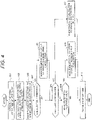
- FIG. 4 is a diagram illustrating a processing flow in the velocity command generation section 10. Details of the processing will be described below.
- Equation 3 From the amount of payload sway x0(0) and a payload sway velocity v0(0) at the time of the stop operation start, an amplitude A0 and a phase ⁇ 0 of the payload sway x0(t) at the time of the stop operation start are estimated by Equations 3 and 4. It is noted that if the velocity of the girder/trolley Vs at the time of the stop operation start is very slow and A0 is below an allowable value of the amount of payload sway, a stop may be reached without subsequent calculations.
- a time duration T2 of v2 and a maximum velocity Vdmax are obtained by Equations 24 and 22.
- Vdmax and r are obtained by Equations 17, 18. If a trapezoidal acceleration thus obtained is equal to or less than a maximum acceleration, it is determined that a trapezoidal wave to be driven is determined, and the flow goes to S10.
- a triangular acceleration is equal to or less than an allowable value (minimum allowable acceleration ⁇ min). If it is equal to or less than the allowable value, a reduction of T2 is made possible by setting r>0. Because of this, a parameter calculation is performed to specify a maximum velocity and an acceleration.
- Parameters of the velocity patterns are calculated as described above. If the triangular wave causes the time duration to increase, using the trapezoidal wave reduces the time duration. This enables a reduction in stopping distance and in time until the payload sway is suppressed and a stop is reached.
- FIG. 5 shows charts for explaining the operation in Example 1, which illustrates temporal changes of the trolley velocity and the amount of payload sway from above.
- deceleration is started according to the first velocity pattern from the time of the stop operation start at which a stop operation start signal 11 is input.
- the trapezoidal velocity command which is the second velocity pattern
- the payload sway produced at the time of the stop operation start and by the deceleration is canceled out by the trapezoidal velocity command, so that the trolley is stopped and subsequent payload sway can be suppressed.
- a stop is enabled by a single application of trapezoidal wave. This enables a shorter stopping distance than that in a method of performing the operation over several times.
- the payload sway produced by deceleration can be canceled out by a single application of the acceleration and deceleration, which in turn enables a reduction in stopping distance with suppressing the payload sway, thereby improving the safety of the crane.
- the payload sway can be suppressed similarly even if the velocity is changed to any given velocity.
- the first velocity pattern and the second velocity pattern may be superposed on each other, i.e., Tw may be smaller than T1.
- FIG. 6 is a diagram illustrating the configuration of the crane according to Example 2.
- a significant difference from Example 1 illustrated in Figure 2 is to have a payload sway amount acquisition device that acquires the amount of payload sway and a payload sway velocity in Figure 6 .
- an amplitude A0 and a phase ⁇ 0 of the payload sway x0 at the time of the stop operation start are used, and they can be obtained by Equations 3 and 4 from the amount of payload sway x0(0) and the payload sway velocity v0(0) at the time of the start of stop which are acquired by the payload sway amount acquisition device.
- the payload sway amount acquisition device is a device for obtaining the amount of payload sway and the payload sway velocity.
- the payload sway amount acquisition device in the example includes a payload sway amount detector 13 that measures the amount of payload sway, and a payload sway velocity arithmetic device that computes the payload sway velocity from the measured amount of payload sway.
- the payload sway amount detector 13 is implemented by use of, for example, a camera or a 3D laser distance sensor which is mounted in a downward direction to the trolley, to observe (measure) sway of the hook 6 or the suspended payload 8.
- a payload sway velocity acquisition device performs, for example, a differentiation operation or a pseudo differentiation operation on the measured amount of payload sway.
- the payload sway velocity acquisition device is configured as a function of the velocity command generation section 10, rather than being separately installed.
- a payload sway amount estimation device may be provided to estimate the amount of payload sway and a payload sway velocity, and the payload sway amount acquisition device may also obtain by estimating the amount of payload sway and a payload sway velocity from the angular frequency wr of a payload sway and a velocity command for the girder/trolley. Therefore, the payload sway amount acquisition device may not detect the amount of payload sway directly from the payload sway amount detector 13.
- the angular frequency wr may be estimated from the rope length L0.
- the function of the payload sway amount estimation device may be configured to perform computations in the velocity command generation section 10.
- VT(s) and X(s) resulting from performing a laplace transform on vt(t) and x(t) are calculated from the following equation.
- X s P s * VT s
- the payload sway amount estimation device may estimate the amount of payload sway by performing a filtering operation in which a transfer function is given by P(s) for vt(t), and may estimate a payload sway velocity by differentiating the obtained amount of payload sway.
- the payload sway produced by deceleration can be canceled out by a single application of the acceleration and deceleration, which in turn enables a reduction in stopping distance with suppressing the payload sway, thereby improving the safety of the crane.
- FIG. 7 is a diagram illustrating the configuration of the crane according to Example 3 of the present invention.
- an obstruction detector 14 is included to detect an obstruction 9 located around the suspended load 8, the trolley 4, and the girder 3.
- a collision determination device 15 is included, which receives a detection signal from the obstruction detector 14, and determines whether a risk of a collision between the obstruction 9 and any of the suspended payload 8, the trolley 4, and the girder 3 is present or absent. If it is determined that the risk of the collision is present, the collision determination device 15 outputs a stop operation start signal 11 to the velocity command generation section 10.
- the obstruction detector 14 observes surroundings of the suspended payload 8 by use of, for example, a camera or a 3D laser distance sensor which is mounted in a downward direction to the trolley 4, in order to detect an obstruction around the suspended payload. If a collision between the detected obstruction and the suspended payload is estimated, the collision determination device 15 immediately outputs a stop operation start signal 11. Upon receiving the stop operation start signal 11, the velocity command generation section 10 generates velocity patterns similarly to those in the above examples.
- the velocity command generation section 10 generates a first velocity pattern for deceleration from the velocity at the time of the deceleration start to a first deceleration end velocity, and a second velocity pattern for acceleration and deceleration to cancel out a payload sway occurring when the horizontal movement device is driven in first velocity pattern. And, the generated velocity patterns are output to the crane control section 12, so that the crane control section 12 controls the velocitys of the girder 3 and/or the trolley 4 to stop the crane.
- Such control operation enables the avoidance of a collision between a suspended load and an obstruction and an accident that an operator is caught in a payload and an obstruction.
- a collision of the crane with a wall, a stopper or another crane running on the same rail may be estimated by use of, for example, a length measurement sensor mounted to the trolley 4 and/or the girder 3 to measure a distance to the wall, the stopper or the other crane. If, upon the estimation, the stop operation start signal is immediately output to stop the crane, the avoidance of a collision between the crane and the wall, the stopper and/or the other crane and a caught accident is enabled.
- a payload sway produced by deceleration can be canceled out by a single application of acceleration and deceleration, which in turn enables a reduction in stopping distance with suppressing the payload sway, thereby improving the safety of the crane. Furthermore, the avoidance of a collision and a caught accident is enabled to provide a further improvement in safety of the crane.
- a payload sway produced by deceleration can be canceled out or mitigated by a single application of acceleration and deceleration, and therefore a reduction in stopping distance while suppressing the payload sway is enabled to provide improved safety of the crane.
- the present invention is not limited to the above some examples, and is intended to embrace various modifications.
- the above examples have been described in detail for the purpose of explaining the present invention clearly, and the present invention is not necessarily limited to including all the components and configurations described above.
- a portion of the configuration in one example may be substituted for configuration in another example, and configuration in one example may be added to configuration in another example.
- addition, deletion, and substitution of another configuration may be made.
- the control on the crane is not limited to the stop control, and the application to deceleration and acceleration to any given velocity (target velocity) is enabled. In this case, maintaining the target velocity constantly within a redetermined range is involved.
- the stopping distance means a moving distance to the target velocity.
Landscapes
- Engineering & Computer Science (AREA)
- Mechanical Engineering (AREA)
- Control And Safety Of Cranes (AREA)
Abstract
Description
- The present invention relates to techniques for controlling the operation of cranes that suspend and carry suspended payloads. In particular, the present invention relates to a crane, a crane controller, a crane control method, and a program for controlling the crane.
- In recent years, the number of situations where an unskilled operator not having much experience runs (operates) a crane is increasing in association with the aging of well-experienced operators of cranes and a shortage of operators due to an increase in the number of installed cranes. In the crane operation by the unskilled operator, there are risks such as misjudgment of the position and height of an obstruction, overlooking of surrounding obstructions, unskillfulness to predict crane behavior such as a payload sway and the like, misoperation due to unfamiliarity with crane operation, and the like. On this account, accidents such as a collision of the payload with an obstruction, an accident that an operator is caught in a payload and an obstruction, and the like may occur more often in the crane operation by an unskilled operator than in the crane operation by a well-experienced operator.
-
PTL 1 discloses a technique as one of countermeasures to prevent such accidents.PTL 1 discloses the control method to stop a crane with suppressing apayload sway, in which, at the time of the start of a stop operation for the crane, a notch or mechanical braking is applied once, and then a reverse notch or mechanical braking is applied once or more than once at the time after one half period of thesway, or alternatively, a reverse notch application or mechanical braking is applied once or more than once at the time after one quarter period of the sway. - PTL 1:
Japanese Patent Application Laid-Open No. Hei 8-324960 - In the method disclosed in
PTL 1, after deceleration by the notch or mechanical braking, the notch is applied one or more times (triangle wave velocity pattern) in order to suppress a payload sway, but the sway can't be completely suppressed by only one operation. As a result, a reduction in stopping distance is not expected. However, it is to be desired that the crane is stopped at once with safety, that is, the stopping distance is shorter with suppressing a payload sway even if an immediate change such as a stop occurs. - Here, when the crane velocity is changed, there is a trade-off between a amplitude of a payload sway and a moving distance, the time to reach a target velocity or the time until velocity variation is within a certain range. Specifically, as a rate of change of crane velocity is increased, the above time or moving distance is shorter, but the payload sway is larger. In particular, the problem is made conspicuous by an abrupt change of velocity. For example, as an example of the velocity change, if the crane is stopped, the stopping distance over which a trolley moves until the crane comes to stop is shorter, but a large payload sway occurs. For mitigating the payload sway, the velocity change time (e.g., deceleration time) may be longer or the control to suppress the payload sway may be added. In this case, there is a problem that, although suppression of the payload sway can be achieved, the stopping distance is longer.
- The present invention has been made in view of such problems and it is an object of the present invention to provide a technique to control crane operation with higher safety in which a distance and/or time required for control can be reduced with suppressing a payload sway.
- To solve the above problems, in the present invention, a second velocity pattern is generated to cancel out an "overlap payload sway" resulting from superposition of a payload sway occurring when control on a crane is started and a payload sway occurring by a first velocity pattern for the crane control ("control" means control in which a target velocity or a velocity change falls within a certain range), and the acceleration and deceleration pattern is used to control the operation of the crane. By way of example, a crane includes: a horizontal movement device that moves, in a horizontal direction, a suspended payload which is suspended by a rope; a velocity command generation section that generates a velocity command for controlling the horizontal movement device; and a crane control section that controls a velocity of the horizontal movement device according to the velocity command. In the crane, as the velocity command, the velocity command generation section generates a first velocity pattern in which a velocity at a velocity change start of the horizontal movement is changed to a predetermined velocity, and generates a second velocity pattern in which acceleration and deceleration are performed to cancel out a third payload sway resulting from superposition of a first payload sway at the velocity change start and a second payload sway occurring in driving according to the first velocity pattern. The crane control section controls the horizontal movement device according to the first velocity pattern and the second velocity pattern that are thus generated.
- The present invention also provides a method of controlling the crane and a program for executing the control method to control the crane.
- It is noted that, as used herein, the term "rope" is defined as representing tools in general capable of being used to suspend a burden, such as chains, cords, bonds, bands, cables and the like as well as the ropes. Advantageous Effects of Invention
- According to the present invention, the payload sway produced by a velocity change can be cancelled or mitigated by a smaller number of operations of acceleration and deceleration. This enables a reduction in distance to a target velocity with suppressing the payload sway. In turn, a higher level of safety of the crane is offered.
-
-
Figure 1 is a diagram illustrating a mechanism of an example crane to which the present invention is directed. -
Figure 2 is a diagram illustrating a configuration of a crane according to Example 1 of the present invention. -
Figure 3 is a chart illustrating velocity patterns generated in Example 1. -
Figure 4 is a diagram illustrating a processing flow in a velocity command generation section of the crane according to Example 1. -
Figure 5 shows charts for explaining an example operation according to Example 1. -
Figure 6 is a diagram illustrating a configuration of a crane according to Example 2 of the present invention. -
Figure 7 is a diagram illustrating a configuration of a crane according to Example 3 of the present invention. - Several examples of embodiments of a crane according to the present invention will now be described with reference to the accompanying drawings.
- Here, the present invention covers all types of cranes capable of moving a suspended payload in the horizontal direction. Specifically, the techniques can be applied to cranes moving a trolley in traverse and travel for a suspended payload (e.g., ceiling crane), as well as cranes performing only one of traverse and travel (e.g., unloader) and so-called crane vehicles. As used herein, the term "crane" includes all types of cranes capable of moving a suspended payload in the horizontal direction. It is noted that the word "horizontal/horizontally" includes curvilinear movement made by an arm of a crane vehicle and/or the like. Stated another way, any movement is included if the movement can cause a payload sway.
- Also, a burden (suspended payload) to be carried by a crane is suspended with a chain, a rope, and/or the like to be carried. In the present invention, as long as a tool can be used to suspend a burden, any tool can be used irrespective of materials, shape, and the like. Therefore, as just mentioned, the term "rope" as used herein is referred as a general term for tools used to suspend a burden.
- Specifically, a "rope" includes not only so-called ropes but also chains, bands, wires, cables, cords, bonds, and the like.
- A crane according to Example 1 in the present invention will now be described with reference to
Figure 1 to Figure 5 . It is noted that, in each figure, like reference signs are used to indicate like equipment (devices/apparatuses) and the explanation about previously discussed equipment may be omitted in the description of subsequent figures. -
Figure 1 is a schematic diagram illustrating the mechanism of a ceiling crane. It should be noted that the present invention is not limited to a ceiling crane as described above. - In
Figure 1 , acrane 1 includes:runways 2 installed along both side walls of a building (not shown); agirder 3 moving on the tops of therunways 2; and atrolley 4 moving along the underside of thegirder 3. A winch (hoist) which is not shown is mounted in a lower portion of thetrolley 4 and is used to wind or unwind arope 5 in order to lift or lower ahook 6 attached at the distal end of therope 5. A suspendedpayload 8 is suspended directly or via awire 7 from thehook 6, so that the suspendedpayload 8 is lifted and lowered as thehook 6 is lifted and lowered. Specifically, thecrane 1 is capable of moving the suspendedpayload 8 in the horizontal direction by means of horizontal movement of the girder 3 (hereinafter referred to simply as "travel") and horizontal movement of the trolley 4 (hereinafter referred to simply as "traverse"), and thecrane 1 is capable of lifting and lowering the suspendedpayload 8 vertically (in the up and down direction) by use of the winch. - In this example, the horizontal movement is performed by the traverse of the
trolley 4 and the travel of thegirder 3. InFigure 1 , thetrolley 4 and thegirder 3 corresponds to a horizontal movement device. Since the present invention is pertinent to the operation of moving the suspended payload horizontally, the following description for Example 1 according to the present invention focuses mainly on the operation of horizontal movement by means of the traverse and the travel. Therefore, in the description in the following examples, the movement of the suspended payload refers to any one or both of the movement by driving the trolley 4 (traverse) and the movement by driving the girder 3 (travel). -
Figure 2 is a diagram illustrating the configuration of the crane according to Example 1 of the present invention.Figure 2 illustrates thecrane 1 operating thetrolley 4 for traverse for the purpose of clear and simple description, in which travel of thegirder 3 is omitted. A drive portion such as a motor/motors and/or the like used to move thetrolley 4 and thegirder 3 is also omitted. - In
Figure 2 ,reference sign 10 denotes a velocity command generation section that generates velocity patterns and the like for use of controlling the horizontal movement device (thegirder 3 and the trolley 4) in order to move the suspendedpayload 8 to a desired position, andFigure 2 shows an example of using a general-purpose computing machine.Reference sign 101 denotes an MPU (Microprocessing Unit) that performs arithmetic processing using programs, data and/or the like contained therein for generation of velocity patterns and/or the like.Reference sign 102 denotes memory to store the programs, the data and/or the like.Reference sign 103 denotes an input/output control section for input of data and signals from the outside and output of signals obtained through the arithmetic processing by MPU and/or the like to the outside.Reference sign 104 denotes a bus for communication of signals and data among components in the velocitycommand generation section 10.Reference sign 12 denotes a crane control section that receives the velocity patterns output from the velocitycommand generation section 10 and controls the velocity of horizontal movement (traverse) of thetrolley 4. Thecrane control section 12 outputs, to thetrolley 4, a control signal according to the received velocity pattern. Alternatively, thecrane control section 12 may provide the function to the velocitycommand generation section 10 so that the control signal may be output from the velocitycommand generation section 10. - Although not shown in
Figure 2 , in addition to thetrolley 4, the velocitycommand generation section 10 outputs velocity patterns for velocity control of horizontal movement (travel) of thegirder 3 in the travel control. On thegirder 3 side, the velocity of horizontal movement (travel) of the suspended payload is controlled based on the velocity pattern. The velocitycommand generation section 10 also receives a rope length L0 which is output from a rope length detector not shown, and a velocity Vs at the time of the stop operation start from a velocity detector also not shown. It is noted that when there is no change in the rope length L0 and the velocity Vs, the data on them may be stored in thememory 102. Note thatreference sign 9 denotes an obstruction. Theobstruction 9 is not always present on the carry route for a suspended load, but the possible presence is assumed inFigure 2 . - It is noted that, in the specification, a description of the deceleration and stop of the crane is provided by way of example, but each example is also applicable to control performed to reach a target velocity in acceleration, deceleration up to a velocity which is slow but not stop, an/or the like. In this case, a velocity when control is initiated is used for a velocity at the time of the deceleration start. The time of the deceleration start may be input from the velocity detector or may be a predicted value based on control.
- Details of the crane control in
Figure 2 will now be described. InFigure 2 , when an operator uses anoperation input device 100 to instruct a direction of moving the suspended payload, the velocitycommand generation section 10 generates a velocity command to move thegirder 3 and thetrolley 4 in a direction corresponding to the instructed moving direction. The crane control section drives thegirder 3 and thetrolley 4 according to the velocity command generated, to move (in this case, cause traverse of) the suspendedpayload 8 horizontally. - For stopping the horizontal movement (traverse, travel), the operator uses the
operation input device 100 to instruct the velocitycommand generation section 10 for a stop operation startsignal 11. For example, push buttons corresponding to the moving directions are disposed on theoperation input device 100. Hence, one of the buttons corresponding to a desired moving direction is pressed for start of the movement, and then the button is released for stop of the movement. In this operation, the velocitycommand generation section 10 receives the stop operation startsignal 11 serving as a trigger for the stop operation start when the push button is released. Alternatively, the stop operation startsignal 11 may be configured to be input by use of a separately disposed stop button or form external equipment. -
Figure 3 is a chart illustrating velocity patterns generated by the velocitycommand generation section 10 when the stop operation startsignal 11 is received. Upon reception of the stop operation startsignal 11, initially, a drive is provided in a first velocity pattern v1 in which a velocity of the girder/trolley is reduced over a time duration T1 from Vs at the time of the stop operation start. - Then, the drive is provided in a second velocity pattern v2 in which acceleration and deceleration are performed with a maximum velocity Vdmax over a time duration T2 after a lapse of Tw from the stop operation start in such a manner as to cancel out the payload sway occurring at the start of the stop operation and the payload sway produced by the drive in v1. The above velocity patterns are obtained the following relational expressions. It is noted that the velocity patterns may be a pattern showing changes in velocity.
- Initially, a transfer function P(s) from a crane velocity command to the amount of payload sway is given by the following equation.

memory 102. - A payload sway x0(t) at the time of the stop operation start is given as the following equation.



- If the first velocity pattern v1 is given by a function v1(t) with respect to time t, the payload sway x1(t) occurring when the trolley is driven in v1(t) can be obtained by performing a laplace transform on v1(t) to determine V1(s), then by performing an inverse laplace transform on X1(s) = P(s)*V1(s), and it is given as follows.


- If the second velocity pattern v2 is given by a function v2(t) with respect to time t, the payload sway x2(t) occurring when the trolley is driven in v2(t) can be obtained by performing a laplace transform on v2(t) to determine v2(s), then by performing an inverse laplace transform on X2(s) = P(s)*V2(s), and it is given as follows.


- For suppressing the payload sway after stopping, the payload sway x01(t) resulting from superposition of x0(t) and x1(t) may be canceled by x2(t).
- The following equation gives x01(t).

Equation 11 are as follows.

- For canceling x01(t) with x2(t), x01(t) and x2(t) may be made identical in phase to cancel out each other's amplitudes. Therefore, θ01 = θ2, A01 = -A2 may be established.
- The following equation is obtained from θ01 = θ2.

- From this, x01(t) at the center time (t = Tw + T2/2) of V2(t) is as follows.

- This states that the time at which x01(t) reaches a maximum and the center time of V2(t) may coincide with each other.
- The following equation is obtained from A01 = -A2.

- Initially, if a set time T for T2 and a set velocity V for Vdmax are given, r is determined as follows. Assuming that T2*wr/2 is minute, Vdmax can be approximated as expressed in the following equation.


- Also, if a set velocity V for Vdmax and a set acceleration α for a trapezoidal acceleration are given, T2 and r may be determined as follows. Assuming that T2*wr/2 is minute, an acceleration can be obtained as expressed in the following equation.


- Further, when r is zero, i.e., a triangular waveform, if a set velocity V for Vdmax is given, T2 is determined as follows. If r = 0, Vdmax is as expressed in the following equation.


- Also, if r = 0, and a set acceleration α for a trapezoidal acceleration is given, T2 and Vdmax may be determined as follows. An acceleration can be obtained as expressed in the following equation.


- A start time Tw of v2(t) is obtained by the following equation.


- Thus, the start time Tw and the time duration T2 of the second velocity pattern v2, the maximum velocity Vdmax, and the upper side/lower side r of the trapezoidal wave are determined.
- It is noted that when the velocity Vs at the time of the stop operation start is very slow, T1 becomes approximate zero. In this case, the payload sway x01(t) resulting from superposition of the payload sway x0(t) at the time of the stop operation start and the payload sway x1(t) by the first velocity pattern becomes only x0(t). From this, the amplitude A01 and the phase θ01 of x01(t) may be assumed as the amplitude A0 and the phase θ0 of x0 (t).
- For reducing the stopping distance, it is desired to reduce the time duration T1 of the first velocity pattern v1(t) and the time duration T2 of the second velocity pattern v2(t). To this end, based on the performance of the girder/trolley, a deceleration of v1(t), a set value V for the maximum velocity of v2(t), and a set value α for an acceleration are desirably taken as high as possible.
-
Figure 4 is a diagram illustrating a processing flow in the velocitycommand generation section 10. Details of the processing will be described below. - At S01, from the amount of payload sway x0(0) and a payload sway velocity v0(0) at the time of the stop operation start, an amplitude A0 and a phase θ0 of the payload sway x0(t) at the time of the stop operation start are estimated by
Equations - At S02, from A0, θ0, Vs, a time duration T1 of the first velocity pattern v1 and an angular frequency wr of a payload sway, amplitudes A01, θ01 of the payload sway x01 resulting from superposition of x0 and the payload sway x1 produced by the drive by v1 are obtained by
Equations - At S03, from a set value V for the maximum velocity in the second velocity pattern v2 in which A01, wr, and the upper side/lower side r of the trapezoidal waveform are zero, i.e., a triangular wave, a time duration T2 of v2 and a maximum velocity Vdmax are obtained by Equations 24 and 22.
- At S04, T2 obtained in S03 is compared with a threshold T2s = 2*((π/2 - θ01)/wr - T1). If T2 > T2s, a reduction of T2 is made possible by setting r>0. Because of this, a parameter calculation is made to specify a maximum velocity and a time duration.
- At S05, taking Vdmax as V and T2 as T2s, Vdmax and r are obtained by Equations 17, 18. If a trapezoidal acceleration thus obtained is equal to or less than a maximum acceleration, it is determined that a trapezoidal wave to be driven is determined, and the flow goes to S10.
- At S06, it is determined whether the acceleration exceeds a maximum acceleration αmax. If it exceeds, a parameter calculation is performed to specify the acceleration such that the acceleration becomes equal to or less than αmax.
- At S07, taking a set value for the acceleration as αmax, T2 and Vdmax are obtained by Equations 26 and 22.
- At S08, it is determined whether a triangular acceleration is equal to or less than an allowable value (minimum allowable acceleration αmin). If it is equal to or less than the allowable value, a reduction of T2 is made possible by setting r>0. Because of this, a parameter calculation is performed to specify a maximum velocity and an acceleration.
- At S09, taking Vdmax as V and an acceleration as αmin, T2, r, and Vdmax are obtained by Equations 20, 21, and 16.
- At S10, Equation 28 is used to calculate start time Tw. First, a calculation is made as n=0, and when Tw<0, a recalculation is made as n=1.
- Parameters of the velocity patterns are calculated as described above. If the triangular wave causes the time duration to increase, using the trapezoidal wave reduces the time duration. This enables a reduction in stopping distance and in time until the payload sway is suppressed and a stop is reached.
-
Figure 5 shows charts for explaining the operation in Example 1, which illustrates temporal changes of the trolley velocity and the amount of payload sway from above. As seen fromFigure 5 , deceleration is started according to the first velocity pattern from the time of the stop operation start at which a stop operation startsignal 11 is input. Then, because of drive by the trapezoidal velocity command which is the second velocity pattern, the payload sway produced at the time of the stop operation start and by the deceleration is canceled out by the trapezoidal velocity command, so that the trolley is stopped and subsequent payload sway can be suppressed. Also, a stop is enabled by a single application of trapezoidal wave. This enables a shorter stopping distance than that in a method of performing the operation over several times. - As described above, according to Example 1, the payload sway produced by deceleration can be canceled out by a single application of the acceleration and deceleration, which in turn enables a reduction in stopping distance with suppressing the payload sway, thereby improving the safety of the crane.
- It will be understood that although the case of stopping the crane has been described in the above example, the payload sway can be suppressed similarly even if the velocity is changed to any given velocity. Also, the first velocity pattern and the second velocity pattern may be superposed on each other, i.e., Tw may be smaller than T1.
- A crane according to Example 2 of the present invention will now be described. It is noted that repetition in the description of commonalities with the above example is avoided.
Figure 6 is a diagram illustrating the configuration of the crane according to Example 2. In Example 2, a significant difference from Example 1 illustrated inFigure 2 is to have a payload sway amount acquisition device that acquires the amount of payload sway and a payload sway velocity inFigure 6 . In the velocity command generation in the previous examples, an amplitude A0 and a phase θ0 of the payload sway x0 at the time of the stop operation start are used, and they can be obtained byEquations - The payload sway amount acquisition device is a device for obtaining the amount of payload sway and the payload sway velocity. The payload sway amount acquisition device in the example includes a payload
sway amount detector 13 that measures the amount of payload sway, and a payload sway velocity arithmetic device that computes the payload sway velocity from the measured amount of payload sway. The payloadsway amount detector 13 is implemented by use of, for example, a camera or a 3D laser distance sensor which is mounted in a downward direction to the trolley, to observe (measure) sway of thehook 6 or the suspendedpayload 8. Also, a payload sway velocity acquisition device performs, for example, a differentiation operation or a pseudo differentiation operation on the measured amount of payload sway. In the example, the payload sway velocity acquisition device is configured as a function of the velocitycommand generation section 10, rather than being separately installed. - Also, a payload sway amount estimation device may be provided to estimate the amount of payload sway and a payload sway velocity, and the payload sway amount acquisition device may also obtain by estimating the amount of payload sway and a payload sway velocity from the angular frequency wr of a payload sway and a velocity command for the girder/trolley. Therefore, the payload sway amount acquisition device may not detect the amount of payload sway directly from the payload
sway amount detector 13. The angular frequency wr may be estimated from the rope length L0. The function of the payload sway amount estimation device may be configured to perform computations in the velocitycommand generation section 10. - For the estimation of the amount of payload sway and a payload sway velocity, when the girder trolley velocity command is vt(t) and the amount of payload sway is x(t), VT(s) and X(s) resulting from performing a laplace transform on vt(t) and x(t) are calculated from the following equation.

- Therefore, the payload sway amount estimation device may estimate the amount of payload sway by performing a filtering operation in which a transfer function is given by P(s) for vt(t), and may estimate a payload sway velocity by differentiating the obtained amount of payload sway.
- As described above, according to Example 2, the payload sway produced by deceleration can be canceled out by a single application of the acceleration and deceleration, which in turn enables a reduction in stopping distance with suppressing the payload sway, thereby improving the safety of the crane.
- A crane according to Example 3 of the present invention will now be described. It is noted that repetition in the description of commonalities with the above examples is avoided.
-
Figure 7 is a diagram illustrating the configuration of the crane according to Example 3 of the present invention. In the example, anobstruction detector 14 is included to detect anobstruction 9 located around the suspendedload 8, thetrolley 4, and thegirder 3. Also, acollision determination device 15 is included, which receives a detection signal from theobstruction detector 14, and determines whether a risk of a collision between theobstruction 9 and any of the suspendedpayload 8, thetrolley 4, and thegirder 3 is present or absent. If it is determined that the risk of the collision is present, thecollision determination device 15 outputs a stop operation startsignal 11 to the velocitycommand generation section 10. - The
obstruction detector 14 observes surroundings of the suspendedpayload 8 by use of, for example, a camera or a 3D laser distance sensor which is mounted in a downward direction to thetrolley 4, in order to detect an obstruction around the suspended payload. If a collision between the detected obstruction and the suspended payload is estimated, thecollision determination device 15 immediately outputs a stop operation startsignal 11. Upon receiving the stop operation startsignal 11, the velocitycommand generation section 10 generates velocity patterns similarly to those in the above examples. Specifically, the velocitycommand generation section 10 generates a first velocity pattern for deceleration from the velocity at the time of the deceleration start to a first deceleration end velocity, and a second velocity pattern for acceleration and deceleration to cancel out a payload sway occurring when the horizontal movement device is driven in first velocity pattern. And, the generated velocity patterns are output to thecrane control section 12, so that thecrane control section 12 controls the velocitys of thegirder 3 and/or thetrolley 4 to stop the crane. Such control operation enables the avoidance of a collision between a suspended load and an obstruction and an accident that an operator is caught in a payload and an obstruction. - Also, a collision of the crane with a wall, a stopper or another crane running on the same rail may be estimated by use of, for example, a length measurement sensor mounted to the
trolley 4 and/or thegirder 3 to measure a distance to the wall, the stopper or the other crane. If, upon the estimation, the stop operation start signal is immediately output to stop the crane, the avoidance of a collision between the crane and the wall, the stopper and/or the other crane and a caught accident is enabled. - With the crane according to Example 3 of the present invention as described above, a payload sway produced by deceleration can be canceled out by a single application of acceleration and deceleration, which in turn enables a reduction in stopping distance with suppressing the payload sway, thereby improving the safety of the crane. Furthermore, the avoidance of a collision and a caught accident is enabled to provide a further improvement in safety of the crane.
- Also, according to each of the examples using the stop control as an example, a payload sway produced by deceleration can be canceled out or mitigated by a single application of acceleration and deceleration, and therefore a reduction in stopping distance while suppressing the payload sway is enabled to provide improved safety of the crane.
- It will be understood that the present invention is not limited to the above some examples, and is intended to embrace various modifications. The above examples have been described in detail for the purpose of explaining the present invention clearly, and the present invention is not necessarily limited to including all the components and configurations described above. Further, a portion of the configuration in one example may be substituted for configuration in another example, and configuration in one example may be added to configuration in another example. Further, for the configuration in each example, addition, deletion, and substitution of another configuration may be made. In particular, the control on the crane is not limited to the stop control, and the application to deceleration and acceleration to any given velocity (target velocity) is enabled. In this case, maintaining the target velocity constantly within a redetermined range is involved. Also, the stopping distance means a moving distance to the target velocity.
-
- 1
- crane,
- 2
- runway,
- 3
- girder,
- 4
- trolley,
- 5
- rope,
- 6
- hook,
- 7
- wire,
- 8
- suspended payload,
- 9
- obstruction,
- 10
- velocity command generation section,
- 11
- stop operation start signal,
- 12
- crane control section,
- 13
- payload sway amount detector,
- 14
- obstruction detector,
- 15
- collision determination device
Claims (20)
- A crane comprising:a horizontal movement device that produces, in a horizontal direction, horizontal movement of a suspended payload which is suspended by a rope;a velocity command generation section that generates a velocity command for controlling the horizontal movement device; anda crane control section that controls a velocity of the horizontal movement device according to the velocity command,wherein as the velocity command, the velocity command generation section generates a first velocity pattern in which a velocity at a velocity change start of the horizontal movement is changed to a predetermined velocity, and generates a second velocity pattern in which acceleration and deceleration are performed to cancel out a third payload sway resulting from superposition of a first payload sway at the velocity change start and a second payload sway occurring in driving according to the first velocity pattern, andthe crane control section controls the horizontal movement device according to the first velocity pattern and the second velocity pattern that are thus generated.
- The crane according to claim 1,
wherein the velocity command generation section uses a deceleration pattern to decelerate and stop the horizontal movement of the crane, as the first velocity pattern. - The crane according to claim 1 or 2,
wherein the crane control section controls the horizontal movement device according to the first velocity pattern from the velocity change start, and controls the horizontal movement device to achieve coincidence between a time at which an amount of payload sway of the third payload sway reaches a maximum and a center time of the second velocity pattern. - The crane according to any one of claims 1 to 3,
wherein the velocity command generation section generates the first velocity pattern by calculating a control start time, a time duration, and a maximum velocity in the second velocity pattern, based on an angular frequency according to a length of the rope, an amplitude and a phase of the third payload sway, a crane velocity at the velocity change start, and time to change a velocity of the first velocity pattern. - The crane according to claim 4,
wherein the velocity command generation section:calculates an amplitude and a phase of the first payload sway based on an amount of payload sway, a payload sway velocity, and an angular frequency in the first payload sway; andcalculates an amplitude and a phase of the third payload sway based on the calculated amplitude, calculated phase, and calculated angular frequency of the first payload sway and deceleration time of a deceleration pattern which is the first velocity pattern. - The crane according to claim 4 or 5,
wherein as the second velocity pattern, the velocity command generation section generates a second velocity pattern showing a trapezoidal wave. - The crane according to claim 6,wherein as the first velocity pattern, the velocity command generation section generates a first velocity pattern in which a velocity change of the horizontal movement indicates acceleration or deceleration at a certain rate, andthe trapezoidal wave satisfies the followingwhere a start time is Tw, a time duration is T2, a maximum velocity is Vdmax, an upper side/lower side of the trapezoidal wave is r, the angular frequency is wr, an amplitude of the third payload sway is A01, and the phase is θ01 (n is 0 or 1).


- The crane according to any one of claims 1 to 7, further comprising a payload sway acquisition section that acquires an amount of payload sway and a payload sway velocity,
wherein the velocity command generation section uses the amount of payload sway and the payload sway velocity to generate the velocity command. - The crane according to claim 8,
wherein the payload sway acquisition section estimates the amount of payload sway and the payload sway velocity from either an angular frequency of the payload sway or the angular frequency obtained from a length of the rope, and the velocity command for the crane. - The crane according to any one of claims 1 to 9, further comprising:an obstruction detector that detects an obstruction to the suspended load and the crane; anda collision determination section that determines whether a risk of a collision between the obstruction detected by the obstruction detector and at least one of the suspended payload and the crane is present or absent, and, if the risk of the collision is present, outputs a stop operation start signal for starting a stop operation to the velocity command generation section.
- A crane control method of controlling a crane having: a horizontal movement device that produces, in a horizontal direction, horizontal movement of a suspended payload which is suspended by a rope; and a velocity command generation section that generates a velocity command for controlling the horizontal movement device; and a crane control section that controls a velocity of the horizontal movement device according to the velocity command,
the method comprising:generating, by the velocity command generation section, as the velocity command, a first velocity pattern in which a velocity at a velocity change start of the horizontal movement is changed to a predetermined velocity;generating, by the velocity command generation section, as the velocity command, a second velocity pattern in which acceleration and deceleration are performed to cancel out a third payload sway resulting from superposition of a first payload sway at the velocity change start and a second payload sway occurring in driving according to the first velocity pattern; andcontrolling, by the crane control section, the horizontal movement device according to the first velocity pattern and the second velocity pattern which are thus generated. - The crane control method according to claim 11, wherein the method comprises using, by the velocity command generation section, a deceleration pattern to decelerate and stop the horizontal movement of the crane, as the first velocity pattern.
- The crane control method according to claim 11 or 12, wherein the method comprises controlling, by the crane control section, the horizontal movement device according to the first velocity pattern from the velocity change start, and controlling the horizontal movement device to achieve coincidence between a time at which an amount of payload sway of the third payload sway reaches a maximum and a center time of the second velocity pattern.
- The crane control method according to any one of claims 11 to 13, wherein the method comprises generating, by the velocity command generation section, the first velocity pattern by calculating a control start time, a time duration, and a maximum velocity in the second velocity pattern, based on an angular frequency according to a length of the rope, an amplitude and a phase of the third payload sway, a crane velocity at the velocity change start, and time to change a velocity of the first velocity pattern.
- The crane control method according to claim 14, the method comprises, by the velocity command generation section,calculating an amplitude and a phase of the first payload sway based on an amount of payload sway, a payload sway velocity, and an angular frequency in the first payload sway, andcalculating an amplitude and a phase of the third payload sway based on the calculated amplitude, calculated phase, and calculated angular frequency of the first payload sway and deceleration time of a deceleration pattern which is the first velocity pattern.
- The crane control method according to claim 14 or 15, wherein the method comprises, as the second velocity pattern, by the velocity command generation section, generating a second velocity pattern showing a trapezoidal wave.
- The crane control method according to claim 16, wherein the method comprises, as the first velocity pattern, by the velocity command generation section, generating a first velocity pattern in which a velocity change of the horizontal movement indicates acceleration or deceleration at a certain rate,
wherein the trapezoidal wave satisfies the following equations:

- The crane control method according to any one of claims 11 to 17,wherein a payload sway acquisition section is further included to acquire an amount of payload sway and a payload sway velocity, andthe velocity command generation section uses the amount of payload sway and the payload sway velocity to generate the velocity command.
- The crane control section according to claim 18, wherein the method comprises estimating, by the payload sway acquisition section, the amount of payload sway and the payload sway velocity from either an angular frequency of the payload sway or the angular frequency obtained from a length of the rope, and the velocity command for the crane.
- The crane control method according to any one of claims 11 to 19,wherein the crane further includes an obstruction detector and a collision determination section, andthe method comprises:by the obstruction detector, detecting an obstruction to the suspended payload and the crane; andby the collision determination section, determining whether a risk of a collision between the obstruction detected by the obstruction detector and at least one of the suspended load and the crane is present or absent, and, if the risk of the collision is present, outputting a stop operation start signal for starting a stop operation to the velocity command generation section.
Applications Claiming Priority (2)
| Application Number | Priority Date | Filing Date | Title |
|---|---|---|---|
| JP2019204401A JP7297645B2 (en) | 2019-11-12 | 2019-11-12 | Crane and crane control method |
| PCT/JP2020/026086 WO2021095296A1 (en) | 2019-11-12 | 2020-07-02 | Crane and crane control method |
Publications (3)
| Publication Number | Publication Date |
|---|---|
| EP4059875A1 true EP4059875A1 (en) | 2022-09-21 |
| EP4059875A4 EP4059875A4 (en) | 2024-03-20 |
| EP4059875B1 EP4059875B1 (en) | 2025-09-10 |
Family
ID=75897481
Family Applications (1)
| Application Number | Title | Priority Date | Filing Date |
|---|---|---|---|
| EP20888560.8A Active EP4059875B1 (en) | 2019-11-12 | 2020-07-02 | Crane and crane control method |
Country Status (5)
| Country | Link |
|---|---|
| EP (1) | EP4059875B1 (en) |
| JP (1) | JP7297645B2 (en) |
| CN (1) | CN114650962B (en) |
| FI (1) | FI4059875T3 (en) |
| WO (1) | WO2021095296A1 (en) |
Families Citing this family (5)
| Publication number | Priority date | Publication date | Assignee | Title |
|---|---|---|---|---|
| JP7747578B2 (en) * | 2022-04-18 | 2025-10-01 | 株式会社日立産機システム | Crane and crane control method |
| JPWO2024181451A1 (en) * | 2023-03-02 | 2024-09-06 | ||
| CN116448188B (en) * | 2023-06-13 | 2023-08-18 | 西安高商智能科技有限责任公司 | Abnormal state monitoring and early warning system for freight winch |
| CN117003120B (en) * | 2023-06-29 | 2026-05-12 | 武汉港迪技术股份有限公司 | Method for detecting equivalent pendulum length of heavy object for anti-shake control |
| WO2026018466A1 (en) * | 2024-07-18 | 2026-01-22 | 三菱電機株式会社 | Motor control device and crane device |
Family Cites Families (13)
| Publication number | Priority date | Publication date | Assignee | Title |
|---|---|---|---|---|
| DE2022745C3 (en) * | 1970-05-09 | 1979-07-19 | Siemens Ag, 1000 Berlin Und 8000 Muenchen | Arrangement for suppressing pendulum oscillations of a load suspended on a rope and transported by a trolley |
| JPS55123882A (en) * | 1979-03-12 | 1980-09-24 | Mitsubishi Electric Corp | Method of controlling cargo work and conveyance equipment |
| JPS56149986A (en) * | 1980-04-22 | 1981-11-20 | Mitsubishi Electric Corp | Steady-rest controlling device for suspension type crane |
| JPS5992892A (en) * | 1982-11-17 | 1984-05-29 | 株式会社日本製鋼所 | Controller for center rest of hanging type conveyor |
| JPS60153392A (en) * | 1984-01-24 | 1985-08-12 | 株式会社東芝 | Safety device for crane |
| JPH0680387A (en) * | 1992-09-01 | 1994-03-22 | Hitachi Kiden Kogyo Ltd | Method for controlling crane positioning and swinging prevention |
| JPH08324960A (en) | 1995-05-26 | 1996-12-10 | Nippon Steel Corp | Crane steady rest control method |
| US5713477A (en) * | 1995-10-12 | 1998-02-03 | Wallace, Jr.; Walter J. | Method and apparatus for controlling and operating a container crane or other similar cranes |
| JPH09156876A (en) * | 1995-12-06 | 1997-06-17 | Mitsui Eng & Shipbuild Co Ltd | Crane swing method |
| JP3632308B2 (en) * | 1996-07-10 | 2005-03-23 | 石川島播磨重工業株式会社 | Stabilizer for container crane |
| JP6684442B2 (en) * | 2016-05-19 | 2020-04-22 | 富士電機株式会社 | Control method and control device for suspension crane |
| JP7020092B2 (en) * | 2017-12-08 | 2022-02-16 | 富士電機株式会社 | Crane operation control device |
| CN108840242B (en) * | 2018-08-31 | 2019-08-16 | 三一海洋重工有限公司 | Crane, monkey and its control method and device |
-
2019
- 2019-11-12 JP JP2019204401A patent/JP7297645B2/en active Active
-
2020
- 2020-07-02 CN CN202080078306.2A patent/CN114650962B/en active Active
- 2020-07-02 WO PCT/JP2020/026086 patent/WO2021095296A1/en not_active Ceased
- 2020-07-02 EP EP20888560.8A patent/EP4059875B1/en active Active
- 2020-07-02 FI FIEP20888560.8T patent/FI4059875T3/en active
Also Published As
| Publication number | Publication date |
|---|---|
| JP2021075372A (en) | 2021-05-20 |
| JP7297645B2 (en) | 2023-06-26 |
| CN114650962A (en) | 2022-06-21 |
| EP4059875B1 (en) | 2025-09-10 |
| EP4059875A4 (en) | 2024-03-20 |
| CN114650962B (en) | 2025-04-22 |
| WO2021095296A1 (en) | 2021-05-20 |
| FI4059875T3 (en) | 2025-10-16 |
Similar Documents
| Publication | Publication Date | Title |
|---|---|---|
| EP4059875B1 (en) | Crane and crane control method | |
| FI126857B (en) | Crane Control | |
| US5967347A (en) | Lowering collision avoidance device of crane | |
| CN114572842B (en) | Control method, device and equipment for inhibiting swinging of grab bucket and storage medium | |
| EP2927178A1 (en) | Crane operation assistance device | |
| US8669724B2 (en) | Method and apparatus for load dependent speed control of a motor | |
| US20210214194A1 (en) | Crane | |
| EP3760569A1 (en) | Crane | |
| CN114180460A (en) | Anti-collision protection method, controller and system for lifting appliance and shore bridge | |
| JP5240253B2 (en) | Elevator control operation device | |
| EP4317043A1 (en) | Crane, and control method for crane | |
| CN112512953B (en) | Crane and crane control method | |
| EP4163245A1 (en) | Dynamic lift-off control device, and crane | |
| JP6280838B2 (en) | Moving device, hoisting machine, crane device, and wheel life estimation method used therefor | |
| JP7717041B2 (en) | Container crane control device | |
| JP4800793B2 (en) | Elevator control device | |
| EP3770103A1 (en) | Crane and crane control method | |
| EP4163244A1 (en) | Dynamic lift-off control device, and crane | |
| JP5809788B2 (en) | Electric hoist with earthing stop mechanism | |
| CN103922225B (en) | Tower machine safety operating control method | |
| RU2312814C1 (en) | Method of and device to prevent swinging of load lifted by load-lifting crane | |
| US20250368477A1 (en) | Method for collision monitoring of a cable-guided load | |
| CN113353803B (en) | Automatic accurate and rapid positioning control method for cyclone well travelling crane | |
| JP2025140400A (en) | crane | |
| HK40114635A (en) | Method and device for operating a boom slewing crane and boom slewing crane |
Legal Events
| Date | Code | Title | Description |
|---|---|---|---|
| STAA | Information on the status of an ep patent application or granted ep patent |
Free format text: STATUS: THE INTERNATIONAL PUBLICATION HAS BEEN MADE |
|
| PUAI | Public reference made under article 153(3) epc to a published international application that has entered the european phase |
Free format text: ORIGINAL CODE: 0009012 |
|
| STAA | Information on the status of an ep patent application or granted ep patent |
Free format text: STATUS: REQUEST FOR EXAMINATION WAS MADE |
|
| 17P | Request for examination filed |
Effective date: 20220613 |
|
| AK | Designated contracting states |
Kind code of ref document: A1 Designated state(s): AL AT BE BG CH CY CZ DE DK EE ES FI FR GB GR HR HU IE IS IT LI LT LU LV MC MK MT NL NO PL PT RO RS SE SI SK SM TR |
|
| DAV | Request for validation of the european patent (deleted) | ||
| DAX | Request for extension of the european patent (deleted) | ||
| A4 | Supplementary search report drawn up and despatched |
Effective date: 20240215 |
|
| RIC1 | Information provided on ipc code assigned before grant |
Ipc: B66C 15/04 20060101ALI20240209BHEP Ipc: B66C 13/06 20060101ALI20240209BHEP Ipc: B66C 13/22 20060101AFI20240209BHEP |
|
| GRAP | Despatch of communication of intention to grant a patent |
Free format text: ORIGINAL CODE: EPIDOSNIGR1 |
|
| STAA | Information on the status of an ep patent application or granted ep patent |
Free format text: STATUS: GRANT OF PATENT IS INTENDED |
|
| INTG | Intention to grant announced |
Effective date: 20250624 |
|
| GRAS | Grant fee paid |
Free format text: ORIGINAL CODE: EPIDOSNIGR3 |
|
| GRAA | (expected) grant |
Free format text: ORIGINAL CODE: 0009210 |
|
| STAA | Information on the status of an ep patent application or granted ep patent |
Free format text: STATUS: THE PATENT HAS BEEN GRANTED |
|
| AK | Designated contracting states |
Kind code of ref document: B1 Designated state(s): AL AT BE BG CH CY CZ DE DK EE ES FI FR GB GR HR HU IE IS IT LI LT LU LV MC MK MT NL NO PL PT RO RS SE SI SK SM TR |
|
| REG | Reference to a national code |
Ref country code: GB Ref legal event code: FG4D |
|
| REG | Reference to a national code |
Ref country code: CH Ref legal event code: EP |
|
| REG | Reference to a national code |
Ref country code: DE Ref legal event code: R096 Ref document number: 602020058723 Country of ref document: DE |
|
| REG | Reference to a national code |
Ref country code: IE Ref legal event code: FG4D |
|
| REG | Reference to a national code |
Ref country code: FI Ref legal event code: FGE |
|
| PG25 | Lapsed in a contracting state [announced via postgrant information from national office to epo] |
Ref country code: NO Free format text: LAPSE BECAUSE OF FAILURE TO SUBMIT A TRANSLATION OF THE DESCRIPTION OR TO PAY THE FEE WITHIN THE PRESCRIBED TIME-LIMIT Effective date: 20251210 |
|
| REG | Reference to a national code |
Ref country code: LT Ref legal event code: MG9D |
|
| REG | Reference to a national code |
Ref country code: NL Ref legal event code: MP Effective date: 20250910 |
|
| PG25 | Lapsed in a contracting state [announced via postgrant information from national office to epo] |
Ref country code: HR Free format text: LAPSE BECAUSE OF FAILURE TO SUBMIT A TRANSLATION OF THE DESCRIPTION OR TO PAY THE FEE WITHIN THE PRESCRIBED TIME-LIMIT Effective date: 20250910 |
|
| PG25 | Lapsed in a contracting state [announced via postgrant information from national office to epo] |
Ref country code: GR Free format text: LAPSE BECAUSE OF FAILURE TO SUBMIT A TRANSLATION OF THE DESCRIPTION OR TO PAY THE FEE WITHIN THE PRESCRIBED TIME-LIMIT Effective date: 20251211 |
|
| PG25 | Lapsed in a contracting state [announced via postgrant information from national office to epo] |
Ref country code: SE Free format text: LAPSE BECAUSE OF FAILURE TO SUBMIT A TRANSLATION OF THE DESCRIPTION OR TO PAY THE FEE WITHIN THE PRESCRIBED TIME-LIMIT Effective date: 20250910 |
|
| PG25 | Lapsed in a contracting state [announced via postgrant information from national office to epo] |
Ref country code: LV Free format text: LAPSE BECAUSE OF FAILURE TO SUBMIT A TRANSLATION OF THE DESCRIPTION OR TO PAY THE FEE WITHIN THE PRESCRIBED TIME-LIMIT Effective date: 20250910 |
|
| PG25 | Lapsed in a contracting state [announced via postgrant information from national office to epo] |
Ref country code: BG Free format text: LAPSE BECAUSE OF FAILURE TO SUBMIT A TRANSLATION OF THE DESCRIPTION OR TO PAY THE FEE WITHIN THE PRESCRIBED TIME-LIMIT Effective date: 20250910 Ref country code: PL Free format text: LAPSE BECAUSE OF FAILURE TO SUBMIT A TRANSLATION OF THE DESCRIPTION OR TO PAY THE FEE WITHIN THE PRESCRIBED TIME-LIMIT Effective date: 20250910 |
|
| PG25 | Lapsed in a contracting state [announced via postgrant information from national office to epo] |
Ref country code: RS Free format text: LAPSE BECAUSE OF FAILURE TO SUBMIT A TRANSLATION OF THE DESCRIPTION OR TO PAY THE FEE WITHIN THE PRESCRIBED TIME-LIMIT Effective date: 20251210 |
|
| PG25 | Lapsed in a contracting state [announced via postgrant information from national office to epo] |
Ref country code: ES Free format text: LAPSE BECAUSE OF FAILURE TO SUBMIT A TRANSLATION OF THE DESCRIPTION OR TO PAY THE FEE WITHIN THE PRESCRIBED TIME-LIMIT Effective date: 20250910 |
|
| REG | Reference to a national code |
Ref country code: AT Ref legal event code: MK05 Ref document number: 1835732 Country of ref document: AT Kind code of ref document: T Effective date: 20250910 |
|
| PG25 | Lapsed in a contracting state [announced via postgrant information from national office to epo] |
Ref country code: NL Free format text: LAPSE BECAUSE OF FAILURE TO SUBMIT A TRANSLATION OF THE DESCRIPTION OR TO PAY THE FEE WITHIN THE PRESCRIBED TIME-LIMIT Effective date: 20250910 |
|
| PG25 | Lapsed in a contracting state [announced via postgrant information from national office to epo] |
Ref country code: SM Free format text: LAPSE BECAUSE OF FAILURE TO SUBMIT A TRANSLATION OF THE DESCRIPTION OR TO PAY THE FEE WITHIN THE PRESCRIBED TIME-LIMIT Effective date: 20250910 |
|
| PG25 | Lapsed in a contracting state [announced via postgrant information from national office to epo] |
Ref country code: AT Free format text: LAPSE BECAUSE OF FAILURE TO SUBMIT A TRANSLATION OF THE DESCRIPTION OR TO PAY THE FEE WITHIN THE PRESCRIBED TIME-LIMIT Effective date: 20250910 |
|
| PG25 | Lapsed in a contracting state [announced via postgrant information from national office to epo] |
Ref country code: IT Free format text: LAPSE BECAUSE OF FAILURE TO SUBMIT A TRANSLATION OF THE DESCRIPTION OR TO PAY THE FEE WITHIN THE PRESCRIBED TIME-LIMIT Effective date: 20250910 |
|
| PG25 | Lapsed in a contracting state [announced via postgrant information from national office to epo] |
Ref country code: IS Free format text: LAPSE BECAUSE OF FAILURE TO SUBMIT A TRANSLATION OF THE DESCRIPTION OR TO PAY THE FEE WITHIN THE PRESCRIBED TIME-LIMIT Effective date: 20260110 |
|
| PG25 | Lapsed in a contracting state [announced via postgrant information from national office to epo] |
Ref country code: PT Free format text: LAPSE BECAUSE OF FAILURE TO SUBMIT A TRANSLATION OF THE DESCRIPTION OR TO PAY THE FEE WITHIN THE PRESCRIBED TIME-LIMIT Effective date: 20260112 Ref country code: CZ Free format text: LAPSE BECAUSE OF FAILURE TO SUBMIT A TRANSLATION OF THE DESCRIPTION OR TO PAY THE FEE WITHIN THE PRESCRIBED TIME-LIMIT Effective date: 20250910 |
|
| PG25 | Lapsed in a contracting state [announced via postgrant information from national office to epo] |
Ref country code: SK Free format text: LAPSE BECAUSE OF FAILURE TO SUBMIT A TRANSLATION OF THE DESCRIPTION OR TO PAY THE FEE WITHIN THE PRESCRIBED TIME-LIMIT Effective date: 20250910 Ref country code: EE Free format text: LAPSE BECAUSE OF FAILURE TO SUBMIT A TRANSLATION OF THE DESCRIPTION OR TO PAY THE FEE WITHIN THE PRESCRIBED TIME-LIMIT Effective date: 20250910 |