EP4059685B1 - Kohlenstofffaserbandmaterial, verstärktes faserlaminat und daraus hergestellter formkörper - Google Patents
Kohlenstofffaserbandmaterial, verstärktes faserlaminat und daraus hergestellter formkörper Download PDFInfo
- Publication number
- EP4059685B1 EP4059685B1 EP20886404.1A EP20886404A EP4059685B1 EP 4059685 B1 EP4059685 B1 EP 4059685B1 EP 20886404 A EP20886404 A EP 20886404A EP 4059685 B1 EP4059685 B1 EP 4059685B1
- Authority
- EP
- European Patent Office
- Prior art keywords
- carbon fiber
- fabric
- tape material
- fiber tape
- bundles
- Prior art date
- Legal status (The legal status is an assumption and is not a legal conclusion. Google has not performed a legal analysis and makes no representation as to the accuracy of the status listed.)
- Active
Links
Images


Classifications
-
- B—PERFORMING OPERATIONS; TRANSPORTING
- B29—WORKING OF PLASTICS; WORKING OF SUBSTANCES IN A PLASTIC STATE IN GENERAL
- B29B—PREPARATION OR PRETREATMENT OF THE MATERIAL TO BE SHAPED; MAKING GRANULES OR PREFORMS; RECOVERY OF PLASTICS OR OTHER CONSTITUENTS OF WASTE MATERIAL CONTAINING PLASTICS
- B29B11/00—Making preforms
- B29B11/14—Making preforms characterised by structure or composition
- B29B11/16—Making preforms characterised by structure or composition comprising fillers or reinforcement
-
- B—PERFORMING OPERATIONS; TRANSPORTING
- B29—WORKING OF PLASTICS; WORKING OF SUBSTANCES IN A PLASTIC STATE IN GENERAL
- B29C—SHAPING OR JOINING OF PLASTICS; SHAPING OF MATERIAL IN A PLASTIC STATE, NOT OTHERWISE PROVIDED FOR; AFTER-TREATMENT OF THE SHAPED PRODUCTS, e.g. REPAIRING
- B29C70/00—Shaping composites, i.e. plastics material comprising reinforcements, fillers or preformed parts, e.g. inserts
- B29C70/04—Shaping composites, i.e. plastics material comprising reinforcements, fillers or preformed parts, e.g. inserts comprising reinforcements only, e.g. self-reinforcing plastics
- B29C70/06—Fibrous reinforcements only
- B29C70/10—Fibrous reinforcements only characterised by the structure of fibrous reinforcements, e.g. hollow fibres
- B29C70/16—Fibrous reinforcements only characterised by the structure of fibrous reinforcements, e.g. hollow fibres using fibres of substantial or continuous length
-
- B—PERFORMING OPERATIONS; TRANSPORTING
- B29—WORKING OF PLASTICS; WORKING OF SUBSTANCES IN A PLASTIC STATE IN GENERAL
- B29C—SHAPING OR JOINING OF PLASTICS; SHAPING OF MATERIAL IN A PLASTIC STATE, NOT OTHERWISE PROVIDED FOR; AFTER-TREATMENT OF THE SHAPED PRODUCTS, e.g. REPAIRING
- B29C70/00—Shaping composites, i.e. plastics material comprising reinforcements, fillers or preformed parts, e.g. inserts
- B29C70/04—Shaping composites, i.e. plastics material comprising reinforcements, fillers or preformed parts, e.g. inserts comprising reinforcements only, e.g. self-reinforcing plastics
- B29C70/06—Fibrous reinforcements only
- B29C70/10—Fibrous reinforcements only characterised by the structure of fibrous reinforcements, e.g. hollow fibres
- B29C70/16—Fibrous reinforcements only characterised by the structure of fibrous reinforcements, e.g. hollow fibres using fibres of substantial or continuous length
- B29C70/20—Fibrous reinforcements only characterised by the structure of fibrous reinforcements, e.g. hollow fibres using fibres of substantial or continuous length oriented in a single direction, e.g. roofing or other parallel fibres
- B29C70/205—Fibrous reinforcements only characterised by the structure of fibrous reinforcements, e.g. hollow fibres using fibres of substantial or continuous length oriented in a single direction, e.g. roofing or other parallel fibres the structure being shaped to form a three-dimensional configuration
- B29C70/207—Fibrous reinforcements only characterised by the structure of fibrous reinforcements, e.g. hollow fibres using fibres of substantial or continuous length oriented in a single direction, e.g. roofing or other parallel fibres the structure being shaped to form a three-dimensional configuration arranged in parallel planes of fibres crossing at substantial angles
-
- B—PERFORMING OPERATIONS; TRANSPORTING
- B32—LAYERED PRODUCTS
- B32B—LAYERED PRODUCTS, i.e. PRODUCTS BUILT-UP OF STRATA OF FLAT OR NON-FLAT, e.g. CELLULAR OR HONEYCOMB, FORM
- B32B1/00—Layered products having a non-planar shape
- B32B1/08—Tubular products
-
- B—PERFORMING OPERATIONS; TRANSPORTING
- B32—LAYERED PRODUCTS
- B32B—LAYERED PRODUCTS, i.e. PRODUCTS BUILT-UP OF STRATA OF FLAT OR NON-FLAT, e.g. CELLULAR OR HONEYCOMB, FORM
- B32B3/00—Layered products comprising a layer with external or internal discontinuities or unevennesses, or a layer of non-planar shape; Layered products comprising a layer having particular features of form
- B32B3/02—Layered products comprising a layer with external or internal discontinuities or unevennesses, or a layer of non-planar shape; Layered products comprising a layer having particular features of form characterised by features of form at particular places, e.g. in edge regions
- B32B3/08—Layered products comprising a layer with external or internal discontinuities or unevennesses, or a layer of non-planar shape; Layered products comprising a layer having particular features of form characterised by features of form at particular places, e.g. in edge regions characterised by added members at particular parts
- B32B3/085—Layered products comprising a layer with external or internal discontinuities or unevennesses, or a layer of non-planar shape; Layered products comprising a layer having particular features of form characterised by features of form at particular places, e.g. in edge regions characterised by added members at particular parts spaced apart pieces on the surface of a layer
-
- B—PERFORMING OPERATIONS; TRANSPORTING
- B32—LAYERED PRODUCTS
- B32B—LAYERED PRODUCTS, i.e. PRODUCTS BUILT-UP OF STRATA OF FLAT OR NON-FLAT, e.g. CELLULAR OR HONEYCOMB, FORM
- B32B3/00—Layered products comprising a layer with external or internal discontinuities or unevennesses, or a layer of non-planar shape; Layered products comprising a layer having particular features of form
- B32B3/10—Layered products comprising a layer with external or internal discontinuities or unevennesses, or a layer of non-planar shape; Layered products comprising a layer having particular features of form characterised by a discontinuous layer, i.e. formed of separate pieces of material
- B32B3/14—Layered products comprising a layer with external or internal discontinuities or unevennesses, or a layer of non-planar shape; Layered products comprising a layer having particular features of form characterised by a discontinuous layer, i.e. formed of separate pieces of material characterised by a face layer formed of separate pieces of material which are juxtaposed side-by-side
- B32B3/16—Layered products comprising a layer with external or internal discontinuities or unevennesses, or a layer of non-planar shape; Layered products comprising a layer having particular features of form characterised by a discontinuous layer, i.e. formed of separate pieces of material characterised by a face layer formed of separate pieces of material which are juxtaposed side-by-side secured to a flexible backing
-
- B—PERFORMING OPERATIONS; TRANSPORTING
- B32—LAYERED PRODUCTS
- B32B—LAYERED PRODUCTS, i.e. PRODUCTS BUILT-UP OF STRATA OF FLAT OR NON-FLAT, e.g. CELLULAR OR HONEYCOMB, FORM
- B32B5/00—Layered products characterised by the non- homogeneity or physical structure, i.e. comprising a fibrous, filamentary, particulate or foam layer; Layered products characterised by having a layer differing constitutionally or physically in different parts
- B32B5/02—Layered products characterised by the non- homogeneity or physical structure, i.e. comprising a fibrous, filamentary, particulate or foam layer; Layered products characterised by having a layer differing constitutionally or physically in different parts characterised by structural features of a fibrous or filamentary layer
- B32B5/022—Non-woven fabric
-
- B—PERFORMING OPERATIONS; TRANSPORTING
- B32—LAYERED PRODUCTS
- B32B—LAYERED PRODUCTS, i.e. PRODUCTS BUILT-UP OF STRATA OF FLAT OR NON-FLAT, e.g. CELLULAR OR HONEYCOMB, FORM
- B32B5/00—Layered products characterised by the non- homogeneity or physical structure, i.e. comprising a fibrous, filamentary, particulate or foam layer; Layered products characterised by having a layer differing constitutionally or physically in different parts
- B32B5/02—Layered products characterised by the non- homogeneity or physical structure, i.e. comprising a fibrous, filamentary, particulate or foam layer; Layered products characterised by having a layer differing constitutionally or physically in different parts characterised by structural features of a fibrous or filamentary layer
- B32B5/026—Knitted fabric
-
- B—PERFORMING OPERATIONS; TRANSPORTING
- B32—LAYERED PRODUCTS
- B32B—LAYERED PRODUCTS, i.e. PRODUCTS BUILT-UP OF STRATA OF FLAT OR NON-FLAT, e.g. CELLULAR OR HONEYCOMB, FORM
- B32B5/00—Layered products characterised by the non- homogeneity or physical structure, i.e. comprising a fibrous, filamentary, particulate or foam layer; Layered products characterised by having a layer differing constitutionally or physically in different parts
- B32B5/22—Layered products characterised by the non- homogeneity or physical structure, i.e. comprising a fibrous, filamentary, particulate or foam layer; Layered products characterised by having a layer differing constitutionally or physically in different parts characterised by the presence of two or more layers which are next to each other and are fibrous, filamentary, formed of particles or foamed
- B32B5/24—Layered products characterised by the non- homogeneity or physical structure, i.e. comprising a fibrous, filamentary, particulate or foam layer; Layered products characterised by having a layer differing constitutionally or physically in different parts characterised by the presence of two or more layers which are next to each other and are fibrous, filamentary, formed of particles or foamed one layer being a fibrous or filamentary layer
- B32B5/26—Layered products characterised by the non- homogeneity or physical structure, i.e. comprising a fibrous, filamentary, particulate or foam layer; Layered products characterised by having a layer differing constitutionally or physically in different parts characterised by the presence of two or more layers which are next to each other and are fibrous, filamentary, formed of particles or foamed one layer being a fibrous or filamentary layer another layer next to it also being fibrous or filamentary
- B32B5/265—Layered products characterised by the non- homogeneity or physical structure, i.e. comprising a fibrous, filamentary, particulate or foam layer; Layered products characterised by having a layer differing constitutionally or physically in different parts characterised by the presence of two or more layers which are next to each other and are fibrous, filamentary, formed of particles or foamed one layer being a fibrous or filamentary layer another layer next to it also being fibrous or filamentary characterised by one fibrous or filamentary layer being a non-woven fabric layer
-
- B—PERFORMING OPERATIONS; TRANSPORTING
- B32—LAYERED PRODUCTS
- B32B—LAYERED PRODUCTS, i.e. PRODUCTS BUILT-UP OF STRATA OF FLAT OR NON-FLAT, e.g. CELLULAR OR HONEYCOMB, FORM
- B32B7/00—Layered products characterised by the relation between layers; Layered products characterised by the relative orientation of features between layers, or by the relative values of a measurable parameter between layers, i.e. products comprising layers having different physical, chemical or physicochemical properties; Layered products characterised by the interconnection of layers
- B32B7/04—Interconnection of layers
- B32B7/05—Interconnection of layers the layers not being connected over the whole surface, e.g. discontinuous connection or patterned connection
-
- B—PERFORMING OPERATIONS; TRANSPORTING
- B32—LAYERED PRODUCTS
- B32B—LAYERED PRODUCTS, i.e. PRODUCTS BUILT-UP OF STRATA OF FLAT OR NON-FLAT, e.g. CELLULAR OR HONEYCOMB, FORM
- B32B7/00—Layered products characterised by the relation between layers; Layered products characterised by the relative orientation of features between layers, or by the relative values of a measurable parameter between layers, i.e. products comprising layers having different physical, chemical or physicochemical properties; Layered products characterised by the interconnection of layers
- B32B7/04—Interconnection of layers
- B32B7/12—Interconnection of layers using interposed adhesives or interposed materials with bonding properties
-
- C—CHEMISTRY; METALLURGY
- C08—ORGANIC MACROMOLECULAR COMPOUNDS; THEIR PREPARATION OR CHEMICAL WORKING-UP; COMPOSITIONS BASED THEREON
- C08J—WORKING-UP; GENERAL PROCESSES OF COMPOUNDING; AFTER-TREATMENT NOT COVERED BY SUBCLASSES C08B, C08C, C08F, C08G or C08H
- C08J5/00—Manufacture of articles or shaped materials containing macromolecular substances
- C08J5/04—Reinforcing macromolecular compounds with loose or coherent fibrous material
- C08J5/0405—Reinforcing macromolecular compounds with loose or coherent fibrous material with inorganic fibres
- C08J5/042—Reinforcing macromolecular compounds with loose or coherent fibrous material with inorganic fibres with carbon fibres
-
- B—PERFORMING OPERATIONS; TRANSPORTING
- B29—WORKING OF PLASTICS; WORKING OF SUBSTANCES IN A PLASTIC STATE IN GENERAL
- B29C—SHAPING OR JOINING OF PLASTICS; SHAPING OF MATERIAL IN A PLASTIC STATE, NOT OTHERWISE PROVIDED FOR; AFTER-TREATMENT OF THE SHAPED PRODUCTS, e.g. REPAIRING
- B29C70/00—Shaping composites, i.e. plastics material comprising reinforcements, fillers or preformed parts, e.g. inserts
- B29C70/04—Shaping composites, i.e. plastics material comprising reinforcements, fillers or preformed parts, e.g. inserts comprising reinforcements only, e.g. self-reinforcing plastics
- B29C70/28—Shaping operations therefor
- B29C70/40—Shaping or impregnating by compression not applied
- B29C70/42—Shaping or impregnating by compression not applied for producing articles of definite length, i.e. discrete articles
- B29C70/44—Shaping or impregnating by compression not applied for producing articles of definite length, i.e. discrete articles using isostatic pressure, e.g. pressure difference-moulding, vacuum bag-moulding, autoclave-moulding or expanding rubber-moulding
-
- B—PERFORMING OPERATIONS; TRANSPORTING
- B29—WORKING OF PLASTICS; WORKING OF SUBSTANCES IN A PLASTIC STATE IN GENERAL
- B29K—INDEXING SCHEME ASSOCIATED WITH SUBCLASSES B29B, B29C OR B29D, RELATING TO MOULDING MATERIALS OR TO MATERIALS FOR MOULDS, REINFORCEMENTS, FILLERS OR PREFORMED PARTS, e.g. INSERTS
- B29K2101/00—Use of unspecified macromolecular compounds as moulding material
- B29K2101/12—Thermoplastic materials
-
- B—PERFORMING OPERATIONS; TRANSPORTING
- B29—WORKING OF PLASTICS; WORKING OF SUBSTANCES IN A PLASTIC STATE IN GENERAL
- B29K—INDEXING SCHEME ASSOCIATED WITH SUBCLASSES B29B, B29C OR B29D, RELATING TO MOULDING MATERIALS OR TO MATERIALS FOR MOULDS, REINFORCEMENTS, FILLERS OR PREFORMED PARTS, e.g. INSERTS
- B29K2103/00—Use of resin-bonded materials as moulding material
- B29K2103/04—Inorganic materials
-
- B—PERFORMING OPERATIONS; TRANSPORTING
- B29—WORKING OF PLASTICS; WORKING OF SUBSTANCES IN A PLASTIC STATE IN GENERAL
- B29K—INDEXING SCHEME ASSOCIATED WITH SUBCLASSES B29B, B29C OR B29D, RELATING TO MOULDING MATERIALS OR TO MATERIALS FOR MOULDS, REINFORCEMENTS, FILLERS OR PREFORMED PARTS, e.g. INSERTS
- B29K2105/00—Condition, form or state of moulded material or of the material to be shaped
- B29K2105/06—Condition, form or state of moulded material or of the material to be shaped containing reinforcements, fillers or inserts
- B29K2105/08—Condition, form or state of moulded material or of the material to be shaped containing reinforcements, fillers or inserts of continuous length, e.g. cords, rovings, mats, fabrics, strands or yarns
- B29K2105/0872—Prepregs
- B29K2105/089—Prepregs fabric
-
- B—PERFORMING OPERATIONS; TRANSPORTING
- B29—WORKING OF PLASTICS; WORKING OF SUBSTANCES IN A PLASTIC STATE IN GENERAL
- B29K—INDEXING SCHEME ASSOCIATED WITH SUBCLASSES B29B, B29C OR B29D, RELATING TO MOULDING MATERIALS OR TO MATERIALS FOR MOULDS, REINFORCEMENTS, FILLERS OR PREFORMED PARTS, e.g. INSERTS
- B29K2307/00—Use of elements other than metals as reinforcement
- B29K2307/04—Carbon
-
- B—PERFORMING OPERATIONS; TRANSPORTING
- B32—LAYERED PRODUCTS
- B32B—LAYERED PRODUCTS, i.e. PRODUCTS BUILT-UP OF STRATA OF FLAT OR NON-FLAT, e.g. CELLULAR OR HONEYCOMB, FORM
- B32B2250/00—Layers arrangement
- B32B2250/20—All layers being fibrous or filamentary
-
- B—PERFORMING OPERATIONS; TRANSPORTING
- B32—LAYERED PRODUCTS
- B32B—LAYERED PRODUCTS, i.e. PRODUCTS BUILT-UP OF STRATA OF FLAT OR NON-FLAT, e.g. CELLULAR OR HONEYCOMB, FORM
- B32B2260/00—Layered product comprising an impregnated, embedded, or bonded layer wherein the layer comprises an impregnation, embedding, or binder material
- B32B2260/02—Composition of the impregnated, bonded or embedded layer
- B32B2260/021—Fibrous or filamentary layer
- B32B2260/023—Two or more layers
-
- B—PERFORMING OPERATIONS; TRANSPORTING
- B32—LAYERED PRODUCTS
- B32B—LAYERED PRODUCTS, i.e. PRODUCTS BUILT-UP OF STRATA OF FLAT OR NON-FLAT, e.g. CELLULAR OR HONEYCOMB, FORM
- B32B2260/00—Layered product comprising an impregnated, embedded, or bonded layer wherein the layer comprises an impregnation, embedding, or binder material
- B32B2260/04—Impregnation, embedding, or binder material
- B32B2260/046—Synthetic resin
-
- B—PERFORMING OPERATIONS; TRANSPORTING
- B32—LAYERED PRODUCTS
- B32B—LAYERED PRODUCTS, i.e. PRODUCTS BUILT-UP OF STRATA OF FLAT OR NON-FLAT, e.g. CELLULAR OR HONEYCOMB, FORM
- B32B2262/00—Composition or structural features of fibres which form a fibrous or filamentary layer or are present as additives
- B32B2262/02—Synthetic macromolecular fibres
- B32B2262/0261—Polyamide fibres
-
- B—PERFORMING OPERATIONS; TRANSPORTING
- B32—LAYERED PRODUCTS
- B32B—LAYERED PRODUCTS, i.e. PRODUCTS BUILT-UP OF STRATA OF FLAT OR NON-FLAT, e.g. CELLULAR OR HONEYCOMB, FORM
- B32B2262/00—Composition or structural features of fibres which form a fibrous or filamentary layer or are present as additives
- B32B2262/10—Inorganic fibres
- B32B2262/106—Carbon fibres, e.g. graphite fibres
-
- B—PERFORMING OPERATIONS; TRANSPORTING
- B32—LAYERED PRODUCTS
- B32B—LAYERED PRODUCTS, i.e. PRODUCTS BUILT-UP OF STRATA OF FLAT OR NON-FLAT, e.g. CELLULAR OR HONEYCOMB, FORM
- B32B2307/00—Properties of the layers or laminate
- B32B2307/30—Properties of the layers or laminate having particular thermal properties
-
- B—PERFORMING OPERATIONS; TRANSPORTING
- B32—LAYERED PRODUCTS
- B32B—LAYERED PRODUCTS, i.e. PRODUCTS BUILT-UP OF STRATA OF FLAT OR NON-FLAT, e.g. CELLULAR OR HONEYCOMB, FORM
- B32B2307/00—Properties of the layers or laminate
- B32B2307/70—Other properties
- B32B2307/718—Weight, e.g. weight per square meter
-
- B—PERFORMING OPERATIONS; TRANSPORTING
- B32—LAYERED PRODUCTS
- B32B—LAYERED PRODUCTS, i.e. PRODUCTS BUILT-UP OF STRATA OF FLAT OR NON-FLAT, e.g. CELLULAR OR HONEYCOMB, FORM
- B32B2405/00—Adhesive articles, e.g. adhesive tapes
Definitions
- the present invention relates to a reinforcing fiber tape material, and a reinforcing fiber laminate and molded body produced by placing and laminating the reinforcing fiber tape material.
- Fiber reinforced plastic including a reinforcing fiber and a resin is used for aviation, space, automobiles, and the like because FRP has the properties such as the light weight and the high strength.
- Examples of the method of molding that achieves both the high productivity and the high strength of FRP include a method of resin transfer molding (RTM) and a method of vacuum-assisted resin transfer molding (VaRTM) in which a resin is later impregnated into a reinforcing fiber laminate and cured.
- the method of RTM is a method of molding FRP by later impregnating and curing a matrix resin, in which a reinforcing fiber laminate including a reinforcing fiber substrate including a dry reinforcing fiber bundle group that is not preimpregnated with a matrix resin is placed in a mold, and a liquid matrix resin having a low viscosity is injected.
- a technique of shortening the time for molding fiber reinforced plastic is used in which during the injection of a resin, the size of a cavity in a mold is set larger than the thickness of a final molded product, and by closing the mold, a reinforced fiber laminate is impregnated at a high speed.
- a method of wet press molding has also been used in which a liquid resin is applied to a reinforcing fiber laminate, and then a mold is clamped to impregnate the resin into the reinforced fiber laminate.
- a reinforcing fiber laminate being impregnated with and cured of a resin is traditionally formed by cutting out a desired shape from a reinforcing fiber substrate such as a textile or a non crimp fabric (NCF) that includes a dry reinforcing fiber bundle group impregnated with no resin and has a fabric form having a certain width (that is, a substantially rectangular shape), and draping and sticking the cut-out product into a three-dimensional shape.
- NCF non crimp fabric
- a method of fiber placement has been attracting attention.
- a reinforced fiber bundle is placed only at a necessary portion so as to obtain a desired shape that matches a product shape.
- a required quantity of reinforcing fibers are placed at a necessary portion, and thus, the quantity of the reinforcing fibers discarded can be significantly reduced by making the reinforcing fibers into a tape-like form and placing the tape material only at required sites.
- the reinforcing fiber substrate manufactured by the method of fiber placement has less crimps in the reinforced fiber bundle and better straightness than conventional textiles and NCFs, so that the FRP obtained by injecting and curing a resin in the substrate has a high mechanical strength.
- Patent Document 1 proposes a carbon fiber tape material with a polymer adhesive bonded to both surfaces thereof, and a method for producing the material.
- a carbon fiber tape with a desired width to be produced with high accuracy by melting the polymer adhesive and then attaching the melted polymer adhesive to a reinforcing fiber bundle group.
- Patent Document 2 proposes a carbon fiber tape material with a non-woven veil bonded to at least one surface thereof, a preform, and a method for producing the preform. This method achieves, with the use of the carbon fiber tape material with the non-woven veil bonded thereto, the effect of increasing the resin permeability in the in-plane direction at the time of resin injection in RTM molding or VaRTM molding. In addition, in the case where a thermoplastic fiber material is used for the non-woven veil, the resulting composite material can be toughened.
- Patent Document 3 proposes a reinforcing sheet material including a reinforcing fiber material with a basis weight of 80 g/m 2 or less and a knitted fabric of a thermoplastic resin material. According to such a configuration, the use of the knitted fabric with flexibility achieves a sheet material that maintains straightness in a thin and wide form without deformations such as curls. In addition, the thin knitted fabric with many voids is used, thus allowing the air inside to be released, and allowing a molded body with few voids (voids) to be obtained.
- Patent Document 4 teaches a textile semi-finished product, which comprises a textile structure and a fixing structure, where the textile structure has a first large number of reinforcing fiber bundles of high-performance fibers, where displacement areas are formed between adjacent reinforcing fiber bundles that are against each other, where the fixing structure fixes the reinforcing fiber bundles depending on the textile structure with a fixing pattern in such a manner that the reinforcing fiber bundles are fixed at least partially and the displacement areas remain at least partially free.
- an apparatus for producing the textile semi-finished product for producing a fiber composite component comprising a device for supplying the above mention textile semi-finished product and a device for applying the fixing pattern for fixing the reinforcing fiber bundle; and (2) a method for producing a textile semi-finished product comprising (a) assembling the textile structure of the first large number of reinforcing fiber bundles of high-performance fibers, where displacement areas are formed between adjacent reinforcing fiber bundles and are mutually displaceable, (b) arranging the fixing structure on the textile structure, and (c) fixing the reinforcing fiber bundle with the fixing structure by applying the fixing pattern relative to the textile structure.
- a carbon fiber tape needs to follow the shape of a mold in attaching the carbon fiber tape directly to the mold.
- the carbon fiber tape is required to have higher deformability as the width of the carbon fiber tape is increases and as the mold shape is more complicated.
- having high productivity is required in laminating the carbon fiber tape and in resin injection in RTM molding and VaRTM molding.
- the deformability of the polymer adhesive is not mentioned in the invention in Patent Document 1.
- the non-woven veil typically has insufficient deformability in the planar direction, because the non-woven veil is formed by randomly orienting short fibers.
- the polymer adhesive is melted, the form of the non-woven veil is lost, and the original deformability of the fabric material will be thus deteriorated.
- the carbon fiber tape material with the non-woven veil bonded to at least one surface thereof is used.
- the non-woven veil has insufficient deformability, because the non-woven veil is formed by randomly orienting short fibers as in Reference 1.
- the fabric with deformability is used. Since reinforcing fiber materials have low basis weight, it is necessary to laminate a large number of sheet materials in order to obtain a desired product thickness, thereby leading to complicated work and decreasing the productivity.
- the invention described in Patent Document 3 relates to a reinforcing sheet material, and fails to suggest the application of the reinforcing sheet material to the method of fiber placement.
- the present invention is intended to solve the problems of the prior art, and specifically, provide a carbon fiber tape material that is favorable in followability to molds and impregnation with matrix resins, and capable of enhancing the productivity in the case of producing a reinforcing fiber laminate by a method of fiber placement and capable of providing a molded body with high mechanical strength when the material is impregnated with a resin and molded.
- the invention is intended to provide a reinforcing fiber laminate and molded body that are obtained from the carbon fiber tape material.
- the carbon fiber tape material according to the present invention is favorable in followability to molds and impregnation with resins, and capable of enhancing the productivity in the case of producing a reinforcing fiber laminate by a method of fiber placement and capable of providing a molded body with high mechanical strength when the material is impregnated with a resin and molded.
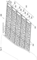
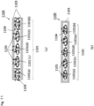
- Fig. 1 shows a schematic view of a carbon fiber tape material not in accordance with the present invention.
- the carbon fiber tape material 100 shown in Fig. 1 has a plurality of carbon fiber bundles 101 integrated with each other by a fabric 103, and the respective carbon fiber bundles are arranged parallel to (in parallel with) each other in a width direction to form a carbon fiber bundle group 102.
- the carbon fiber bundle for use in the present invention for example, a carbon fiber bundle subjected to sizing treatment in advance can also be used.
- the sizing treatment is performed, thereby allowing the convergency of the carbon fiber bundle to be improved, and allowing the generation of fuzz to be suppressed.
- the carbon fiber bundle for use in the present invention may have an organic fiber mixed with a carbon fiber.
- the number of single fibers in the carbon fiber bundle 101 is less than 1 K, the yarn width of the carbon fiber bundle 101 is narrow, and defects such as twisting are likely to occur.
- the carbon fiber basis weight of the carbon fiber bundle 101 is high, and when the carbon fiber bundles 101 are aligned by the method of fiber placement to obtain a substrate, the carbon fiber basis weight per layer is excessively high, and there is thus a possibility that the allowable range of the design of the fiber orientation will be narrowed.
- the carbon fiber tape material 100 includes a plurality of carbon fiber bundles 101 mutually integrated with the fabric 103, thereby allowing the number and weight of carbon fiber filaments per unit length of the carbon fiber tape material to be increased.
- the time of placing and laminating the carbon fiber tape material, required to achieve a desired fiber volume content can be shortened to improve the productivity.
- the fabric 103 is made of one or more thermoplastic resins.
- the thermoplastic resin refers to a thermoplastic resin such as a polyamide resin, a polyester resin, a polyethylene terephthalate resin, a polyvinyl formal resin, a polyether sulfone resin, a phenoxy resin, or a polycarbonate resin, furthermore, a thermoplastic elastomer (a polystyrene-based resin, a polyolefin-based resin, a polyurethane-based resin, a polyester-based resin, a polyamide-based resin, a polybutadiene-based resin, a polyisoprene-based resin, a fluorine-based resin, an acrylonitrile-based thermoplastic elastomer, or the like), a copolymer or a modified product thereof, a resin produced by blending two or more of these resins, or the like.
- a thermoplastic resin such as a polyamide resin, a polyester resin, a
- These resins can be formed into a fiber to have the form of a woven fabric (textile, knitted fabric) or a non-woven fabric, or can be formed into a film as the fabric 103.
- This fabric 103 is partially melted to be integrated with the carbon fiber bundle group 102.
- the fabric 103 it is important for the fabric 103 to have deformability. More specifically, it is important for the fabric elongation rate with a load of 80 mN/50 mm applied to the fabric in at least one direction of the fabric to be 5% to 100%, and further preferably 15% to 100%.
- the use of a deformable fabric allows the deformability of the tape to be improved, and allows the carbon fiber tape to follow the shape of a mold in the case of directly attaching the tape to the mold by the method of fiber placement.
- the fabric elongation rate is less than 5%, the fabric has insufficient deformability and the carbon fiber tape fails to follow the mold shape.
- FIG. 8 shows a method for measuring the fabric elongation rate.
- FIG. 8(a) shows the condition of the fabric 803 before applying a certain load. The fabric is cut into a specified size, specified marks 808 are put on the fabric, an inter-mark distance L 0 is measured, and then the fabric is chucked by a clamp 807 as shown in FIG. 8(a) . Thereafter, a load is applied.
- FIG. 8(b) shows the condition of the fabric 803 after applying the certain load. As shown in Fig. 8(b) , the inter-mark distance L 1 after the application of the certain load is measured, thereby allowing the elongation rate to be calculated from the designated formula.
- the fabric is peeled off from the tape material, and the elongation rate is then measured in accordance with the above-mentioned procedure.
- the carbon fiber tape material according to the present invention it is important for the carbon fiber tape material according to the present invention to have a basis weight excluding fabric between 120 g/m 2 and 400 g/m 2 .
- the basis weight of the carbon fiber tape material excluding the fabric is less than 120 g/m 2 , the number of sheets of the carbon fiber tape material laminated for obtaining a laminate with a desired basis weight is increased in placing the carbon fiber tape material by the method of fiber placement, thereby increasing the time required for the lamination, which results in a limitation in further improvement in productivity.
- the basis weight of the carbon fiber tape material excluding the fabric is more than 400 g/m 2 , the number of sheets of the carbon fiber tape material laminated for obtaining a laminate with a desired basis weight is excessively small, and there is a possibility that the degree of freedom in designing the fiber orientation may be reduced.
- the basis weight is preferably 160 g/m 2 to 300 g/m 2 .
- the fabric 103 desirably has regularity.
- the wording of "having regularity" means that a certain structural form is continuously repeated in the longitudinal direction of the fabric (i.e., the longitudinal direction of the carbon fiber tape material).
- the fabric with regularity include knitted fabrics and textiles.
- the knitted fabrics and the textiles have structural forms continuously repeated in the longitudinal direction, and the positions where the fibers are located is determined by the structure, and thus, the knitted fabrics and the textiles can be considered as materials that are less likely to vary or deviate in fiber basis weight as a fabric.
- fabrics without regularity include non-woven fabrics (non-woven veil).
- Examples of the features of the non-woven fabric include: having a configuration obtained by randomly dispersing short fibers and then bonding the fibers to each other, and thus having difficulty in showing the above-mentioned fabric elongation rate; and having no structural form continuously repeated in the longitudinal direction, and thus easily varying or deviating in fiber orientation and basis weight.
- a woven structure such as plain weave, twill weave, and satin weave, a warp knit structure or a weft knit structure such as denbigh, code, atlas, chain, inlay, satin, half, and tulle, or a combination thereof can be used.
- the basis weight of the fabric 103 is preferably more than 2 g/m 2 and 40 g/m 2 or less, further preferably more than 4 g/m 2 and 20 g/m 2 or less.
- the basis weight of the fabric 103 is 2 g/m 2 or less, the material of the fabric is easily broken, thereby making desired deformability less likely to be obtained.
- the thickness of the fabric is reduced, thereby making it difficult to sufficiently secure the matrix resin flow path in impregnation.
- the thickness of the interlayer reinforcing material in the molded body is reduced, thereby making it difficult to reinforce the interlayers between laminated fiber bundles.
- the basis weight of the fabric 103 is more than 40 g/m 2
- the carbon fiber tape material undergoes an increase in thickness, thereby making the thickness of the reinforcing fiber laminate with the carbon fiber tape material used likely be larger than a desired product thickness, that is, making it difficult to make the reinforcing fiber laminate with the carbon fiber tape material used into the near net shape of a desired molded body.
- the interlayer reinforcement material of a molded body molded with the use of the reinforcing fiber laminate is likely to undergo an increase in thickness, thereby making it difficult to increase the fiber content (Vf: %) in the molded body.
- the fabric 103 can be used not only for the purpose of improving the deformability of the tape, but also for the purpose of ensuring a flow path for a matrix resin in resin impregnation, and for the purpose of strengthening the interval between the layers by using a resin including a material exhibiting high toughness.
- a gap 106 is preferably provided between the plurality of carbon fiber bundles 101 constituting the carbon fiber tape material 100.
- the presence of the gap 106 between the plurality of carbon fiber bundles 101 constituting the carbon fiber tape material 100 makes it easy to ensure a flow path for to matrix resin in the case of the material being used as a substrate by arrangement in one direction in the method of fiber placement. Also in the case of the material being used as a substrate by arranging a plurality of carbon fiber tape materials 100 in one direction without any gap in the method of fiber placement, the fluidity of a matrix resin in molding is more easily ensured when a gap provided between the plurality of carbon fiber bundles 101 fixed in one carbon fiber tape materials 100.
- the gap 106 between the carbon fiber bundles is preferably 0.1 mm to 1 mm.
- the gap 106 is smaller than 0.1 mm, the flow path of the matrix resin is reduced, thus increasing the time required for molding, and there is a possibility of leading to a decrease in productivity.
- the gap 106 is larger than 1 mm, there is a possibility, in molding the reinforcing fiber laminate obtained by laminating the carbon fiber tape material in the method of fiber placement, that the tape in the upper layer partially may fall into the gap between the carbon fiber bundles in the lower layer, thereby decreasing the straightness of the carbon fiber bundles. As a result, the compression characteristics of the molded body obtained may be deteriorated.
- the tape width of the carbon fiber tape material 100 is preferably 2 mm to 2000 mm, further preferably 5 mm to 100 mm.
- the tape width of the carbon fiber tape material 100 is smaller than 2 mm, there is a need to place more carbon fiber tape materials in the fiber placement step, thereby making the productivity likely to be decreased.
- the tape width of the carbon fiber tape material 100 is more than 2000 mm, a large-size apparatus for manufacturing the tape easily leads to an increase in tape cost, which is not preferred.
- a carbon fiber tape material 200 shown in Fig. 2 is a schematic perspective view of another carbon fiber tape material not in accordance with the present invention.
- the carbon fiber tape material 200 has, as with the carbon fiber tape material shown in Fig. 1 , a fabric 203 with regularity located on at least one surface of a carbon fiber bundle group 202, and the fabric 203 is integrated with the carbon fiber bundle group 202 with a resin binder 204 attached to at least one surface of the carbon fiber bundle group 202 for the purpose of keeping the form of each carbon fiber bundle 201.
- the other configuration is the same as the carbon fiber tape material 100 shown in Fig. 1 .
- the resin binder 204 may have the form of a particle or the form of a non-woven fabric.
- the resin binder 204 is not to be considered limited to these forms, and may be a film, a mesh, an emulsion, a coating, or an auxiliary yarn wound around the carbon fiber bundle.
- thermoplastic resin such as a polyamide resin, a polyester resin, a polyethylene terephthalate resin, a polyvinyl formal resin, a polyether sulfone resin, a phenoxy resin, or a polycarbonate resin, a phenol-based resin, a phenoxy resin, an epoxy resin, a polystyrene-based resin, a polyolefin-based resin, a polyurethane-based resin, a polyester-based resin, a polyamide-based resin, a polybutadiene-based resin, a polyisoprene-based resin, a fluorine-based resin, a thermoplastic elastomer such as an acrylonitrile-based thermoplastic elastomer, or the like, a copolymer or a modified product thereof, a resin produced by blending two or more of these resins, or the like can be used.
- a thermoplastic resin such as a polyamide resin, a polyester resin, a polyethylene tere
- resin binders can be used to obtain the adhesive function of sticking the layers to one another when the reinforcing fiber laminate is formed. Furthermore, the resin binders can be used for the purpose of ensuring a flow path for a matrix resin in resin impregnation, and for the purpose of strengthening the interval between the layers by using a resin including a material exhibiting high toughness.
- the resin binder 204 kept visible may be attached to and subjected to partial impregnation on the surfaces of the carbon fiber bundles 201, thereby binding the plurality of filaments included in the carbon fiber bundle, or the resin binder 204 may be subjected to impregnation in the carbon fiber bundles 201 so as to be invisible from the surface, thereby binding the plurality of filaments included in the carbon fiber bundle to each other.
- the resin binder may be wound around the carbon fiber bundles 201, or the carbon fiber bundle 201 may be coated with the resin binder.
- the amount of the resin binder required for fixing the carbon fiber bundles 201 is preferably 25% by weight or less, more preferably 20% by weight or less, further preferably 15% by weight or less, based on the weight of the carbon fiber bundles 201.
- the amount of the resin binder is more than 25% by weight, the improved viscosity of the matrix resin makes the fluidity likely to be decreased in molding a reinforcing fiber laminate obtained by arranging and laminating the tape material by the method of fiber placement, and thus, the productivity is likely to be decreased.
- the softening point Ts (°C) of the fabric 203 is preferably higher than the softening point of the resin binder 204.
- the softening point of the thermoplastic resin with the lowest softening point among the multiple types of thermoplastic resins is regarded as the softening point Ts (°C) of the fabric 203.
- heating and pressurizing at a temperature that is higher than the softening point of the resin binder 204 and lower than the softening point of the fabric 203 can integrate the fabric 203 and the carbon fiber bundle group 202 with the melted resin binder 204 as an adhesive.
- the fabric 203 keeps the form of structure without melting, and the carbon fiber tape material 200 with excellent deformability can be obtained without impairing the deformability of the fabric 203.
- the softening point (°C) of the resin binder 204 is preferably a temperature that is higher than 40°C and lower than the softening point Ts (°C) of the fabric 203.
- the use of such a resin binder can, at the temperature returned to room temperature by cooling or the like after the viscosity is reduced by heating, fix the plurality of filaments constituting the carbon fiber bundle to each other, and more reliably keep a certain form as a carbon fiber bundle.
- the form of the carbon fiber bundle when the form of the carbon fiber bundle is kept constant, the form of the carbon fiber bundle can be kept from collapsing in the case of the placement of the carbon fiber tape material 200 on a mold, and the application of a pressure or a tension to the carbon fiber tape material 200 by the method of fiber placement.
- the gaps 206 provided between the carbon fiber bundles 201 can be kept without being crushed, and the flow path of the matrix resin at the time of molding can be more reliably secured.
- the "softening point” refers to a temperature at which a resin material such as a fabric or a resin binder softens/melts when the resin material reaches a temperature equal to or higher than the temperature.
- the melting point is referred to as the softening point; when the resin material is an amorphous polymer, the glass transition point is referred to as the softening point.
- FIG. 3 shows a schematic perspective view of still another carbon fiber tape material 300 not in accordance with the present invention.
- a fabric 303 with regularity is placed on at least one surface (both surfaces in Fig. 3 ) of a carbon fiber bundle group 302 that has a plurality of carbon fiber bundles 301 arranged in parallel.
- the fabric 303 is integrated with the carbon fiber bundle group 302 with a resin binder 304 attached to the surface of the carbon fiber bundle group 302 for the purpose of keeping the form of each carbon fiber bundle 301.
- a resin binder 304 attached to the surface of the carbon fiber bundle
- the adhesive regions 305 are formed not continuously but discretely (intermittently) in the fiber orientation direction of the carbon fiber bundles 301 in at least a part of the carbon fiber tape material 300.
- the "adhesive region” herein refers to a region where the fabric 303 and the carbon fiber bundle group 302 are bonded to each other with the resin binder 304 interposed therebetween.
- the fabric 303 and the carbon fiber bundle group 302 are bonded to each other in at least some of the adhesive regions to be integrated with each other, thereby allowing the form of the carbon fiber tape material to be kept.
- the carbon fiber tape material 300 shown in Fig. 3 has the same configuration as the carbon fiber tape material 200 shown in Fig. 2 except for the foregoing respects.
- the adhesive regions 305 are preferably formed discretely in the fiber orientation direction of the carbon fiber bundles 301 as described above.
- the adhesive regions 305 extends over the entire tape to bond the carbon fiber bundle group 302 and the fabric 303 over the entire surface of the tape, the positions of the thermoplastic fibers constituting the fabric will be completely fixed by bonding to the carbon fiber bundles, thereby deteriorating the inherent deformability of the fabric.
- the adhesive regions 305 are discretely dispersed in the fiber orientation direction, there is room for the fabric to be free to move locally, thus making it possible to suppress deterioration in fabric deformability due to bonding.
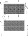
- a carbon fiber tape material 400 shown in Fig. 4(b) is a plan view of a carbon fiber tape material according to the present invention.
- adhesive regions 405 where a fabric and a carbon fiber bundle group are bonded with a resin binder interposed therebetween are discretely formed in the fiber orientation direction of carbon fiber bundles 401 in the entire area of the carbon fiber tape material 400.
- the adhesive regions 405 are discretely formed over the entire area of the carbon fiber tape material 400, and there is thus much room for the fabric to be free to move locally, thereby allowing excellent tape deformability to be exhibited. According to the embodiment of FIG.
- the two carbon fiber bundles 401(a) and 401(b) located at both ends in the direction orthogonal to the fiber orientation direction of the carbon fiber bundles are continuously bonded to the fabric 403, thus allowing the fabric 403 to be kept from peeling off from the tape end, and allowing a balance to be achieved between the tape stability and the tape deformability.
- each adhesive region 405 is preferably provided so as not to extend over a plurality of carbon fiber bundles.
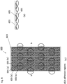
- a carbon fiber tape material 500 shown in Fig. 5(a) is a plan view of another carbon fiber tape material not in accordance with the present invention.
- Figs. 5(b) and 5(c) respectively show a b-b cross section and a c-c cross section of the carbon fiber tape material 500.
- adhesive regions 505 where a fabric and a carbon fiber bundle group are bonded with a resin binder interposed therebetween are discretely formed in the fiber orientation direction of carbon fiber bundles 501 in the entire area of the carbon fiber tape material 500.
- Each adhesive region 505 is provided so as not to extend over a plurality of carbon fiber bundles.
- the adhesive regions are shifted in the fiber orientation direction of the carbon fibers.
- the adhesive regions provided respectively in the adjacent carbon fiber bundles are shifted in the fiber orientation direction of the carbon fibers, thereby allowing the relative positions of the adjacent carbon fiber bundles to vary independently without being fixed.
- the carbon fiber bundles are each allowed to move independently following the movements of parts of the fabric with the bundles bonded thereto.
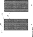
- adhesive regions may be provided as in Fig. 6(a) .
- adhesive regions for adjacent carbon fiber bundles (for example, 601(a) and 601(b)), adhesive regions (for example, adhesive regions 605(a) and 605(b)) are not shifted in the fiber orientation direction of the carbon fibers.
- the positions of the adjacent carbon fiber bundles are fixed, thereby making it difficult for each carbon fiber bundle to move independently following the movements of parts of the fabric with the bundles bonded thereto.
- Fig. 6 (a) is a plan view of the carbon fiber tape material 600
- Fig. 6 (b) is a b-b sectional view of the carbon fiber tape material 600.
- the adhesive regions 505 are provided to be substantially shifted in the fiber orientation direction of the carbon fibers, the following is more preferred. More specifically, in an arbitrary cross section in a direction orthogonal to the fiber orientation direction of the carbon fibers, the adhesive regions (for example, 505(a) and 505(b)) are kept from co-existing on the adjacent carbon fiber bundles (for example, 501(a) and 501(b)). In other words, in the adjacent carbon fiber bundles (for example, 501(a) and 501(b)), the adhesive regions (for example, 505(a) and 505(b)) are preferably provided so as to be shifted (as shown in Fig.
- the part with such a cross section as shown in Fig. 5(b) preferably falls within the range of 30% or less of all cross sections collected at regular intervals in the fiber orientation direction of the carbon fibers.
- Figs. 7(a) and 7(b) show plan views of another carbon fiber tape material 700 not in accordance with the present invention. While Figs. 3 to 6 mentioned above show aspects in which the adhesive regions are discretely formed in the fiber orientation direction of the carbon fiber bundles, adhesive regions 705 in which a fabric and a carbon fiber bundle group are bonded with a resin binder interposed therebetween are discretely formed in a direction orthogonal to the fiber orientation direction of the carbon fiber bundles in the carbon fiber tape material 700 shown in Fig. 7 . Even such a configuration allows adjacent carbon fiber bundles to move independently without fixing the relative positions of the carbon fiber bundles, thus allowing the carbon fiber tape material to demonstrate favorable deformations.
- the carbon fiber tape material according to the present invention configured as described above allows the following shear deformation performance to be delivered. More specifically, the tensile load F [N] measured at a shear angle ⁇ [°] in the range from 0° to 45° with the use of a picture frame method by a two sides gripping method has no maximum value for the tensile load F [N] at the shear angle ⁇ [°] between 0° and 1.0°, the maximum value of the tensile load F [N] measured at the shear angle ⁇ [°] in the range from 0° to 45° is higher than 0.5 [N], and ⁇ F/ ⁇ is larger than 0.1 and smaller than 1.0 at the shear angle ⁇ [°] between 0.1° and 1.0°.
- Fig. 9 shows a schematic view of a picture frame method by a two sides gripping method.
- One or more carbon fiber tape materials 900 of 220 mm in length are arranged in parallel without any gap, and prepared such that the sum of the overall widths is 150 mm.
- the carbon fiber tape materials 900 are attached to a picture frame jig 904 so as to grip the two sides at both ends of the carbon fiber tape such that the gripping section 902 is 200 mm, the measurement angle ⁇ [°] is 90°, and the longitudinal direction of the carbon fiber tape is parallel to two sides 903 of the picture frame gripping no carbon fiber tape material.
- the picture frame jig is attached to a universal testing machine, not shown, such that the measurement angle ⁇ [°] is 90°, and then the picture frame jig is pulled in the vertical direction at a speed of 50 mm/min, and the tensile force F [N] and the measurement angle ⁇ at the time are measured. Thereafter, the shear angle ⁇ [°] calculated from the following formula and ⁇ F/ ⁇ at ⁇ [°] between 0.1° and 1.0° are calculated.
- ⁇ ° 90 ° ⁇ ⁇ °
- Fig. 10 shows an example of a shear angle-tensile load graph in the case of applying the picture frame method by the two sides gripping method to the carbon fiber tape material according to the present invention.
- Fig. 10(a) is a shear angle-tensile load graph in the case of testing at the shear angle ⁇ [°] from 0 to 45
- Fig. 10(b) is an enlargement of the same graph around the shear angle ⁇ [°] from 0 to 1.
- the tensile load F preferably has no maximum value at the shear angle ⁇ [°] between 0° and 1.0° in the case of testing at the shear angle ⁇ [°] from 0° to 45°. Having the maximum value of the tensile load F [N] at the shear angle ⁇ [°] between 0° and 1.0° means that the carbon fiber tape material fails to keep the form until the shear angle ⁇ [°] reaches 1.0°, thereby collapsing. In this case, the value of ⁇ F/ ⁇ fails to be evaluated as the shear deformation performance of the carbon fiber tape material.
- ⁇ F/ ⁇ at the shear angle ⁇ [°] between 0.1° and 1.0° is preferably smaller than 1.0, more preferably smaller than 0.4, and still more preferably less than 0.2.
- ⁇ F/ ⁇ is preferably larger than 0.1.
- ⁇ F/ ⁇ is 0.1 or less, the application of a slight force causes the carbon fiber tape material to undergo a significant shear deformation, thereby impairing the stability of the carbon fiber tape material.
- the maximum value of the tensile load F is preferably more than 0.5 N, further preferably more than 1.0 N in the case of testing with the shear angle ⁇ [°] from 0° to 45°.
- the carbon fiber tape material fails to keep the tape form, due to peeling off between the carbon fiber bundle and the fabric material, and etc., when the maximum value of the tensile load F is 0.5 N or less.
- a fabric 1103 is preferably placed on both surfaces of a carbon fiber bundle group 1102 to provide a tubular body ( Fig. 11(a) ) or a bag-like body ( Fig. 11(b) ) as a whole. More specifically, as shown in Fig.
- two carbon fiber bundles 1101(a) and 1101(b) located at both ends in the direction orthogonal to the fiber orientation direction of the carbon fiber bundles 1101 are preferably, on both surfaces thereof, bonded to the fabric 1103, such that the carbon fiber bundles 1101(a) and 1101(b) at the both ends and the fabric 1103 at the both surfaces form a tubular closed system.
- the placement of the fabric on the both surfaces of the carbon fiber bundle group as described above makes it possible to keep the carbon fiber bundles from being detached during handling of the carbon fiber tape material, and makes it possible to improve the production stability of the carbon fiber tape material.
- the reinforcing fiber laminate with the carbon fiber tape material used is preferably impregnated with a matrix resin to obtain a fiber reinforced resin composite.
- the above-described configuration allows an obtained fiber reinforced resin composite to be completely impregnated to the inside thereof with the resin, thereby providing a high mechanical property.
- the carbon fiber tape material according to the present invention will be described based on examples.
- Table 1 shows the conditions and results of examples and a comparative example.
- a knitted fabric material: polyamide, basis weight: 8 g/m 2
- material polyamide, basis weight: 8 g/m 2
- regularity was used, which was obtained by warp knitting into a tulle structure with the use of a tricot machine.
- one carbon fiber bundle was drawn out from a bobbin, the width was reduced without slitting while adjusting the thickness, and thereafter, heat-meltable binder particles (average particle size: 0.2 mm) with a softening point temperature of 80°C were sprayed onto the surface of the carbon fiber bundle.
- the binder particles were sprayed so as to have a proportion of 5% by weight (the weight of the obtained carbon fiber bundle was considered as 100%), and then melted and cooled to obtain a carbon fiber bundle of 4.8 mm in yarn width with a form fixed.
- the picture frame method by the two sides grip method was performed.
- Three carbon fiber tape materials with a length of 220 mm and a width of 50 mm were arranged in parallel, and marks were put on the gripping section such that the gripping interval was 200 mm.
- the three carbon fiber tape materials arranged in parallel were attached to the picture frame jig shown in Fig. 9 so as to grip two sides such that the gripping section was 200 mm and that the measurement angle ⁇ [°] was 90°, and subjected to a measurement.
- the carbon fiber tape materials obtained in the manner as mentioned above were aligned in one direction and then placed on a stand so as to provide a gap of 0.7 mm between the respective carbon fiber tape materials; the carbon fiber tape materials were repeatedly cut and placed into a square shape of 300 mm ⁇ 300 mm to prepare a sheet substrate.
- the adjacent carbon fiber tape materials were bonded and integrated by lapping adjacent knitted fabrics by 1 mm and heating the lapped part at 200°C to prepare a sheet substrate.
- the obtained sheet substrate was placed in a pyramid (tetrahedral) shaped mold (bottom surface: equilateral triangle of 14 cm on a side, height: 7 cm), and the upper mold was lowered for press draping while applying a tension to the sheet substrate, and then, the lower mold was heated at 120°C for 10 minutes. As a result, the sheet substrate exhibited a favorable draping property without large wrinkles.
- the upper mold was closed, and the lower mold was then heated at 120°C for 10 minutes. As a result, a favorable reinforcing fiber laminate was obtained without large wrinkles.
- the obtained reinforcing fiber laminate was placed in the lower mold in the above-described pyramid shape, vacuum bagging was performed with the use of a bagging film, and the mold was then placed in an oven at an atmospheric temperature of 100°C. Thereafter, a matrix resin (epoxy resin) was injected and cured in an atmosphere at 180°C. As a result, a favorable molded body without any resin-unimpregnated site was obtained.
- a matrix resin epoxy resin
- a carbon fiber tape was obtained in the same manner as in Example 1 except for the following point.
- a carbon fiber tape was obtained in the same manner as in Example 1 except for the following point.
- a carbon fiber tape was obtained in the same manner as in Example 1 except for the following point.
- a carbon fiber tape was obtained in the same manner as in Example 1 except for the following point.
- a carbon fiber tape was obtained in the same manner as in Example 1 except for the following point.
- the sheet substrate was found to be twisted and wrinkled, and so any favorable reinforcing fiber laminate was not obtained.
- the carbon fiber tape material according to the present invention and the reinforcing fiber laminate with the material used are excellent in the impregnation property with a matrix resin, and the molded body obtained with the use of the reinforcing fiber laminate is also suitably used, in particular, for large members for aircraft, automobiles, ships, and the like and members for general industrial applications such as windmill blades.
Landscapes
- Engineering & Computer Science (AREA)
- Textile Engineering (AREA)
- Chemical & Material Sciences (AREA)
- Mechanical Engineering (AREA)
- Composite Materials (AREA)
- Health & Medical Sciences (AREA)
- Manufacturing & Machinery (AREA)
- Materials Engineering (AREA)
- Inorganic Chemistry (AREA)
- Chemical Kinetics & Catalysis (AREA)
- Medicinal Chemistry (AREA)
- Polymers & Plastics (AREA)
- Organic Chemistry (AREA)
- Reinforced Plastic Materials (AREA)
- Woven Fabrics (AREA)
- Laminated Bodies (AREA)
Claims (10)
- Kohlefaserbandmaterial (400), wobei eine Kohlefaserbündelgruppe (402), die mehrere Kohlefaserbündel (401) umfasst, die parallel zu einer Faserorientierungsrichtung angeordnet sind, in ein Gewebe (403) integriert ist, wobei das Kohlefaserbandmaterial (400) die folgenden (a) bis (c) erfüllt:(a) das Gewebe (403) umfasst ein oder mehrere thermoplastische Harze;(b) das Kohlefaserbandmaterial (400), ausgenommen das Gewebe (403), hat ein Flächengewicht zwischen 120 g/m2 und 400 g/m2 ; und(c) eine Gewebedehnungsrate Ep (%) bei einer auf das Gewebe (403) aufgebrachten Last von 80 mN/50 mm beträgt 5 % bis 100 % in mindestens einer Richtung des Gewebes (403)
 Ep: Gewebedehnungsrate (%)L0: ursprüngliche Gewebelänge zwischen Markierungen (mm)L1: Gewebelänge bei Lastaufbringung (mm),wobei die Kohlefaserbündelgruppe (402) und das Gewebe (403) durch Binden integriert sind, wobei ein Harzbindemittel an mindestens einer Oberfläche der Kohlefaserbündelgruppe (402) angebracht ist, die dazwischen angeordnet ist,wobei ein Klebebereich (405), in dem das Gewebe (403) und die Kohlefaserbündelgruppe (402) mit dem dazwischen angeordneten Harzbindemittel gebunden sind, in der Faserorientierungsrichtung der Kohlefaserbündel (401) in mindestens einem Teil des Kohlefaserbandmaterials (400) diskret ausgebildet ist, dadurch gekennzeichnet, dassvon der Kohlefaserbündelgruppe (402) zwei Kohlefaserbündel (401(a), 401(b)), die sich an beiden Enden in einer Richtung orthogonal zu der Faserorientierungsrichtung der Kohlefaserbündel (401) befinden, kontinuierlich an das Gewebe (403) in der Faserorientierungsrichtung der Kohlefaserbündel (401) gebunden sind, und die anderen Kohlefaserbündel (401(c), 401(d), 401(e)), die sich zwischen den zwei Kohlefaserbündeln (401(a), 401(b)) befinden, intermittierend an das Gewebe (403) in der Faserorientierungsrichtung der Kohlefaserbündel (401) gebunden sind.
 - Kohlefaserbandmaterial (400) nach Anspruch 1, wobei das Gewebe (403) Regelmäßigkeit hat.
- Kohlefaserbandmaterial (400) nach Anspruch 1 oder 2, wobei ein Spalt von 0,1 mm bis 1 mm zwischen den Kohlefaserbündeln (401) vorgesehen ist.
- Kohlefaserbandmaterial (400) nach einem der Ansprüche 1 bis 3, wobei das Kohlefaserbandmaterial (400) eine Bandbreite von 2 mm bis 2000 mm hat.
- Kohlefaserbandmaterial (400) nach einem der Ansprüche 1 bis 4, wobei von dem Klebebereich (405), in dem das Gewebe (403) und die Kohlefaserbündelgruppe (402) mit dem dazwischen angeordneten Harzbindemittel gebunden sind, der Klebebereich (405) in der Faserorientierungsrichtung der Kohlefaser (401) in den benachbarten Kohlefaserbündeln (401) verschoben ist.
- Kohlefaserbandmaterial (400) nach einem der Ansprüche 1 bis 4, wobei ein Klebebereich (405), in dem das Gewebe (403) und die Kohlefaserbündelgruppe (402) mit dem dazwischen angeordneten Harzbindemittel gebunden sind, in einer Richtung orthogonal zu der Faserorientierung der Kohlefaserbündel (401) in mindestens einem Teil des Kohlefaserbandmaterials (400) diskret ausgebildet ist.
- Kohlefaserbandmaterial (400) nach einem der Ansprüche 1 bis 6, wobei eine Zuglast F [N], gemessen bei einem Scherwinkel θ [°] in einem Bereich von 0° bis 45° unter Verwendung eines Bildrahmenverfahrens durch ein Zwei-Seiten-Greifverfahren, keinen Maximalwert für die Zuglast F [N] bei dem Scherwinkel θ [°] zwischen 0° und 1,0° hat, der Maximalwert der Zuglast F [N], gemessen bei dem Scherwinkel θ [°] in dem Bereich von 0° bis 45°, höher als 0,5 [N] ist und ΔF/Δθ größer als 0,1 und kleiner als 1,0 bei dem Scherwinkel θ [°] zwischen 0,1° und 1,0° ist.
- Kohlefaserbandmaterial (400) nach einem der Ansprüche 1 bis 7, wobei das Gewebe (403) eine Form eines röhrenförmigen Körpers oder eines beutelartigen Körpers hat.
- Verstärkungsfaserlaminat, umfassend das Kohlefaserbandmaterial (400) nach einem der Ansprüche 1 bis 8.
- Formkörper, umfassend das Verstärkungsfaserlaminat nach Anspruch 9.
Applications Claiming Priority (3)
| Application Number | Priority Date | Filing Date | Title |
|---|---|---|---|
| JP2019203908 | 2019-11-11 | ||
| JP2019203907 | 2019-11-11 | ||
| PCT/JP2020/041312 WO2021095623A1 (ja) | 2019-11-11 | 2020-11-05 | 炭素繊維テープ材料、ならびにそれを用いた強化繊維積層体および成形体 |
Publications (3)
| Publication Number | Publication Date |
|---|---|
| EP4059685A1 EP4059685A1 (de) | 2022-09-21 |
| EP4059685A4 EP4059685A4 (de) | 2023-12-20 |
| EP4059685B1 true EP4059685B1 (de) | 2025-06-25 |
Family
ID=75911486
Family Applications (1)
| Application Number | Title | Priority Date | Filing Date |
|---|---|---|---|
| EP20886404.1A Active EP4059685B1 (de) | 2019-11-11 | 2020-11-05 | Kohlenstofffaserbandmaterial, verstärktes faserlaminat und daraus hergestellter formkörper |
Country Status (8)
| Country | Link |
|---|---|
| US (1) | US20220379523A1 (de) |
| EP (1) | EP4059685B1 (de) |
| JP (1) | JP7683217B2 (de) |
| CN (1) | CN114616090B (de) |
| AU (1) | AU2020383077B2 (de) |
| ES (1) | ES3037296T3 (de) |
| TW (1) | TW202124135A (de) |
| WO (1) | WO2021095623A1 (de) |
Families Citing this family (2)
| Publication number | Priority date | Publication date | Assignee | Title |
|---|---|---|---|---|
| JP7661725B2 (ja) * | 2021-03-09 | 2025-04-15 | 東レ株式会社 | 炭素繊維テープ材 |
| CN117963416B (zh) * | 2024-03-02 | 2024-07-16 | 青岛环球输送带有限公司 | 一种碳纤维芯橡胶输送带 |
Family Cites Families (38)
| Publication number | Priority date | Publication date | Assignee | Title |
|---|---|---|---|---|
| JP3505754B2 (ja) * | 1993-12-02 | 2004-03-15 | 東レ株式会社 | プリプレグおよびその製造方法 |
| JP2791875B2 (ja) * | 1996-01-31 | 1998-08-27 | 川崎重工業株式会社 | 高含浸性三次元織物、並びに該織物を用いた炭素繊維強化複合材料及びセラミックス系複合材料 |
| KR20010014068A (ko) * | 1997-07-23 | 2001-02-26 | 사가라 아스히코 | 1방향성 강화섬유 복합기재 |
| EP1125728B1 (de) * | 1999-03-23 | 2011-10-05 | Toray Industries, Inc. | Basismaterial aus faserverstärktem verbundwerkstoff, dessen herstellungsprozess sowie daraus hergestellte vorformen |
| WO2000061363A1 (en) | 1999-04-08 | 2000-10-19 | Mitsubishi Rayon Co., Ltd. | Preform for composite material and composite material |
| JP2001064406A (ja) * | 1999-08-31 | 2001-03-13 | Toray Ind Inc | 繊維強化複合材用プリフォームおよびこれを用いてなる繊維強化複合材ならびにこれらの製造方法 |
| JP4613298B2 (ja) | 2004-12-01 | 2011-01-12 | 東邦テナックス株式会社 | 複合シートとそれを用いた平滑な表面を有する複合材料 |
| JP2009019202A (ja) | 2007-06-12 | 2009-01-29 | Toray Ind Inc | 成形材料、プリフォームおよび繊維強化樹脂 |
| FR2939069B1 (fr) | 2008-11-28 | 2013-03-01 | Hexcel Reinforcements | Nouveau materiau intermediaire de largeur constante pour la realisation de pieces composites par procede direct. |
| CN102471968B (zh) | 2010-07-13 | 2012-12-19 | 三井化学株式会社 | 发泡成型用非织造布层叠体 |
| WO2012011437A1 (ja) * | 2010-07-23 | 2012-01-26 | 日産自動車株式会社 | 電動車両のトルク異常判定装置 |
| DE102010050079A1 (de) * | 2010-10-29 | 2012-05-03 | Premium Aerotec Gmbh | Partiell fixiertes textiles Halbzeug |
| RU2013127219A (ru) * | 2010-11-16 | 2014-12-27 | Торэй Индастриз, Инк. | Конструкционный основовязаный лист и ламинат на его основе |
| WO2012086682A1 (ja) * | 2010-12-24 | 2012-06-28 | 東レ株式会社 | 炭素繊維集合体の製造方法および炭素繊維強化プラスチックの製造方法 |
| CA2853281C (en) * | 2011-10-24 | 2021-08-24 | Hanwha Azdel, Inc. | Deep draw composites and methods of using them |
| JP6284310B2 (ja) * | 2013-07-12 | 2018-02-28 | 株式会社クラレ | 繊維基材テープまたはシート、その製造方法および繊維強化複合材料 |
| JP5994060B2 (ja) | 2013-11-15 | 2016-09-21 | 八田経編株式会社 | 熱可塑性樹脂補強シート材及びその製造方法 |
| US10226903B2 (en) | 2014-01-09 | 2019-03-12 | Toyota Motor Europe | Reinforced plastic material having high smoothness |
| EP3160720B1 (de) | 2014-06-30 | 2018-11-21 | Cytec Industries Inc. | Trockenes faserförmiges band zur herstellung einer vorform |
| GB201417769D0 (en) * | 2014-10-08 | 2014-11-19 | Rolls Royce Plc | Composite article |
| EP3023241B1 (de) * | 2014-11-21 | 2017-05-31 | Tape Weaving Sweden AB | Trockene bandförmige Faserverstärkung |
| US20200139642A1 (en) * | 2014-12-17 | 2020-05-07 | E.I. Dupont De Nemours And Company | Glass and carbon fiber composites and uses thereof |
| EP3112111A1 (de) * | 2015-07-02 | 2017-01-04 | Honda Motor Co., Ltd. | Faserband zur herstellung von faserverstärkten teilen und verfahren zur fertigung eines derartigen faserbands |
| RU2721112C2 (ru) * | 2015-12-25 | 2020-05-15 | Торэй Индастриз, Инк. | Препрег и способ его изготовления |
| JP6946666B2 (ja) | 2016-03-02 | 2021-10-06 | 東レ株式会社 | 強化繊維積層シートおよび繊維強化樹脂成形体 |
| US10000615B1 (en) | 2017-02-23 | 2018-06-19 | Hexcel Corporation | Retaining compressive strength of thermoplastic-toughened epoxy composites under hot and wet conditions |
| WO2018052080A1 (ja) * | 2016-09-14 | 2018-03-22 | 三菱ケミカル株式会社 | 積層基材およびその製造方法 |
| JP7087337B2 (ja) | 2016-10-19 | 2022-06-21 | 東レ株式会社 | 強化繊維基材、強化繊維積層体および繊維強化樹脂 |
| JP2019099987A (ja) | 2017-11-29 | 2019-06-24 | 東レ株式会社 | 強化繊維基材、強化繊維積層体および繊維強化樹脂 |
| JP2019111710A (ja) | 2017-12-22 | 2019-07-11 | 東レ株式会社 | 炭素繊維テープ材及びその積層シート基材 |
| RU2020131289A (ru) | 2018-03-06 | 2022-04-06 | Торэй Индастриз, Инк. | Сухой ленточный материал для выкладки волокна, способ его производства, ламинат армирующего волокна и пластиковое формованное изделие, произведенное с армированным волокном |
| CN112533753A (zh) | 2018-08-09 | 2021-03-19 | 东丽株式会社 | 增强纤维带材料及其制造方法、使用了增强纤维带材料的增强纤维层叠体及纤维增强树脂成型体 |
| JP2020029011A (ja) | 2018-08-21 | 2020-02-27 | 東レ株式会社 | 強化繊維テープ材料およびそれにマトリックス樹脂を含浸・硬化させた繊維強化樹脂成形体 |
| US20210008849A1 (en) | 2019-07-09 | 2021-01-14 | Lanxess Deutschland Gmbh | Multilayer composite material |
| CN211074959U (zh) | 2019-10-24 | 2020-07-24 | 江苏天鸟高新技术股份有限公司 | 碳纤维展宽布细编穿刺织物 |
| CN211522081U (zh) | 2019-12-27 | 2020-09-18 | 中冶建筑研究总院有限公司 | 一种快速连接用frp纤维胶带 |
| CN111251673A (zh) | 2020-03-06 | 2020-06-09 | 山东宽原新材料科技有限公司 | 一种短切纤维增强热塑性预浸织物结构及其制备、应用 |
| CN212555292U (zh) | 2020-03-06 | 2021-02-19 | 山东宽原新材料科技有限公司 | 一种短切纤维增强热塑性预浸织物结构 |
-
2020
- 2020-11-05 EP EP20886404.1A patent/EP4059685B1/de active Active
- 2020-11-05 JP JP2020564017A patent/JP7683217B2/ja active Active
- 2020-11-05 CN CN202080075938.3A patent/CN114616090B/zh active Active
- 2020-11-05 AU AU2020383077A patent/AU2020383077B2/en active Active
- 2020-11-05 US US17/773,639 patent/US20220379523A1/en active Pending
- 2020-11-05 ES ES20886404T patent/ES3037296T3/es active Active
- 2020-11-05 WO PCT/JP2020/041312 patent/WO2021095623A1/ja not_active Ceased
- 2020-11-09 TW TW109138968A patent/TW202124135A/zh unknown
Also Published As
| Publication number | Publication date |
|---|---|
| TW202124135A (zh) | 2021-07-01 |
| ES3037296T3 (en) | 2025-09-30 |
| CN114616090B (zh) | 2024-04-05 |
| EP4059685A4 (de) | 2023-12-20 |
| US20220379523A1 (en) | 2022-12-01 |
| CN114616090A (zh) | 2022-06-10 |
| JP7683217B2 (ja) | 2025-05-27 |
| AU2020383077B2 (en) | 2025-12-18 |
| AU2020383077A1 (en) | 2022-06-09 |
| WO2021095623A1 (ja) | 2021-05-20 |
| EP4059685A1 (de) | 2022-09-21 |
| JPWO2021095623A1 (de) | 2021-05-20 |
Similar Documents
| Publication | Publication Date | Title |
|---|---|---|
| US11421089B2 (en) | Prepreg sheet, method for manufacturing same, unit layer with a covering material, method for manufacturing fiber-reinforced composite, and fiber-reinforced composite | |
| CA2635855C (en) | Reinforcing fiber base material for preforms, process for the production of laminates thereof, and so on | |
| US9770844B2 (en) | Fibre reinforced composites | |
| EP3437851B1 (de) | Verstärkte faserlaminatschicht, faserverstärkter harzformkörper und verfahren zur herstellung einer verstärkten faserlaminatschicht | |
| EP4059685B1 (de) | Kohlenstofffaserbandmaterial, verstärktes faserlaminat und daraus hergestellter formkörper | |
| US12480238B2 (en) | Unidirectional laid nonwoven and use thereof | |
| AU2018293693A1 (en) | Materials comprising shape memory alloy wires and methods of making these materials | |
| JP7467840B2 (ja) | 強化繊維基材、強化繊維積層体および繊維強化樹脂 | |
| CN111699210B (zh) | 纤维铺放用干式带材料及其制造方法、以及使用其的增强纤维层叠体及纤维增强树脂成型体 | |
| EP3835037A1 (de) | Verstärktes faserbandmaterial und verfahren zu dessen herstellung, faserverstärkter harzformkörper und verstärkter faserschichtkörper unter verwendung von verstärktem faserbandmaterial | |
| EP3960796A1 (de) | Verfahren zur herstellung eines formkörpers aus faserverstärktem verbundwerkstoff, verstärkungsfasersubstrat und formkörper aus faserverstärktem verbundwerkstoff | |
| WO2019149650A1 (en) | Composite material comprising metallic wires and method for making it | |
| JP2007126793A (ja) | 積層体の裁断方法とプリフォーム基材及びそれを用いたプリフォームの製造方法 | |
| JP7661725B2 (ja) | 炭素繊維テープ材 | |
| JP4817651B2 (ja) | Frp用プリフォーム基材及びプリフォームの製造方法 | |
| JP2007260930A (ja) | プリフォーム基材及びプリフォームの製造方法 | |
| JP2013032487A (ja) | 強化繊維基材およびその製造方法 | |
| JP2025084310A (ja) | 強化繊維基材 | |
| JP2023050344A (ja) | 樹脂注入成形用強化繊維基材 |
Legal Events
| Date | Code | Title | Description |
|---|---|---|---|
| STAA | Information on the status of an ep patent application or granted ep patent |
Free format text: STATUS: THE INTERNATIONAL PUBLICATION HAS BEEN MADE |
|
| PUAI | Public reference made under article 153(3) epc to a published international application that has entered the european phase |
Free format text: ORIGINAL CODE: 0009012 |
|
| STAA | Information on the status of an ep patent application or granted ep patent |
Free format text: STATUS: REQUEST FOR EXAMINATION WAS MADE |
|
| 17P | Request for examination filed |
Effective date: 20220412 |
|
| AK | Designated contracting states |
Kind code of ref document: A1 Designated state(s): AL AT BE BG CH CY CZ DE DK EE ES FI FR GB GR HR HU IE IS IT LI LT LU LV MC MK MT NL NO PL PT RO RS SE SI SK SM TR |
|
| DAV | Request for validation of the european patent (deleted) | ||
| DAX | Request for extension of the european patent (deleted) | ||
| A4 | Supplementary search report drawn up and despatched |
Effective date: 20231122 |
|
| RIC1 | Information provided on ipc code assigned before grant |
Ipc: B29C 70/44 20060101ALI20231116BHEP Ipc: B29C 70/16 20060101ALI20231116BHEP Ipc: B29C 43/12 20060101ALI20231116BHEP Ipc: D06M 17/00 20060101ALI20231116BHEP Ipc: B32B 5/28 20060101ALI20231116BHEP Ipc: B32B 5/26 20060101ALI20231116BHEP Ipc: B29K 105/10 20060101ALI20231116BHEP Ipc: B29K 105/08 20060101ALI20231116BHEP Ipc: B29B 11/16 20060101AFI20231116BHEP |
|
| GRAP | Despatch of communication of intention to grant a patent |
Free format text: ORIGINAL CODE: EPIDOSNIGR1 |
|
| STAA | Information on the status of an ep patent application or granted ep patent |
Free format text: STATUS: GRANT OF PATENT IS INTENDED |
|
| INTG | Intention to grant announced |
Effective date: 20250324 |
|
| GRAS | Grant fee paid |
Free format text: ORIGINAL CODE: EPIDOSNIGR3 |
|
| GRAA | (expected) grant |
Free format text: ORIGINAL CODE: 0009210 |
|
| STAA | Information on the status of an ep patent application or granted ep patent |
Free format text: STATUS: THE PATENT HAS BEEN GRANTED |
|
| AK | Designated contracting states |
Kind code of ref document: B1 Designated state(s): AL AT BE BG CH CY CZ DE DK EE ES FI FR GB GR HR HU IE IS IT LI LT LU LV MC MK MT NL NO PL PT RO RS SE SI SK SM TR |
|
| P01 | Opt-out of the competence of the unified patent court (upc) registered |
Free format text: CASE NUMBER: APP_23429/2025 Effective date: 20250516 |
|
| REG | Reference to a national code |
Ref country code: GB Ref legal event code: FG4D |
|
| REG | Reference to a national code |
Ref country code: CH Ref legal event code: EP |
|
| REG | Reference to a national code |
Ref country code: CH Ref legal event code: EP |
|
| REG | Reference to a national code |
Ref country code: IE Ref legal event code: FG4D |
|
| REG | Reference to a national code |
Ref country code: DE Ref legal event code: R096 Ref document number: 602020053523 Country of ref document: DE |
|
| REG | Reference to a national code |
Ref country code: ES Ref legal event code: FG2A Ref document number: 3037296 Country of ref document: ES Kind code of ref document: T3 Effective date: 20250930 |
|
| PG25 | Lapsed in a contracting state [announced via postgrant information from national office to epo] |
Ref country code: FI Free format text: LAPSE BECAUSE OF FAILURE TO SUBMIT A TRANSLATION OF THE DESCRIPTION OR TO PAY THE FEE WITHIN THE PRESCRIBED TIME-LIMIT Effective date: 20250625 |
|
| REG | Reference to a national code |
Ref country code: LT Ref legal event code: MG9D |
|
| PG25 | Lapsed in a contracting state [announced via postgrant information from national office to epo] |
Ref country code: NO Free format text: LAPSE BECAUSE OF FAILURE TO SUBMIT A TRANSLATION OF THE DESCRIPTION OR TO PAY THE FEE WITHIN THE PRESCRIBED TIME-LIMIT Effective date: 20250925 Ref country code: GR Free format text: LAPSE BECAUSE OF FAILURE TO SUBMIT A TRANSLATION OF THE DESCRIPTION OR TO PAY THE FEE WITHIN THE PRESCRIBED TIME-LIMIT Effective date: 20250926 |
|
| PG25 | Lapsed in a contracting state [announced via postgrant information from national office to epo] |
Ref country code: BG Free format text: LAPSE BECAUSE OF FAILURE TO SUBMIT A TRANSLATION OF THE DESCRIPTION OR TO PAY THE FEE WITHIN THE PRESCRIBED TIME-LIMIT Effective date: 20250625 |
|
| PG25 | Lapsed in a contracting state [announced via postgrant information from national office to epo] |
Ref country code: HR Free format text: LAPSE BECAUSE OF FAILURE TO SUBMIT A TRANSLATION OF THE DESCRIPTION OR TO PAY THE FEE WITHIN THE PRESCRIBED TIME-LIMIT Effective date: 20250625 |
|
| PGFP | Annual fee paid to national office [announced via postgrant information from national office to epo] |
Ref country code: FR Payment date: 20250930 Year of fee payment: 6 |
|
| PG25 | Lapsed in a contracting state [announced via postgrant information from national office to epo] |
Ref country code: RS Free format text: LAPSE BECAUSE OF FAILURE TO SUBMIT A TRANSLATION OF THE DESCRIPTION OR TO PAY THE FEE WITHIN THE PRESCRIBED TIME-LIMIT Effective date: 20250925 |
|
| PG25 | Lapsed in a contracting state [announced via postgrant information from national office to epo] |
Ref country code: LV Free format text: LAPSE BECAUSE OF FAILURE TO SUBMIT A TRANSLATION OF THE DESCRIPTION OR TO PAY THE FEE WITHIN THE PRESCRIBED TIME-LIMIT Effective date: 20250625 |
|
| REG | Reference to a national code |
Ref country code: NL Ref legal event code: MP Effective date: 20250625 |
|
| PG25 | Lapsed in a contracting state [announced via postgrant information from national office to epo] |
Ref country code: NL Free format text: LAPSE BECAUSE OF FAILURE TO SUBMIT A TRANSLATION OF THE DESCRIPTION OR TO PAY THE FEE WITHIN THE PRESCRIBED TIME-LIMIT Effective date: 20250625 |
|
| PG25 | Lapsed in a contracting state [announced via postgrant information from national office to epo] |
Ref country code: PT Free format text: LAPSE BECAUSE OF FAILURE TO SUBMIT A TRANSLATION OF THE DESCRIPTION OR TO PAY THE FEE WITHIN THE PRESCRIBED TIME-LIMIT Effective date: 20251027 |
|
| REG | Reference to a national code |
Ref country code: AT Ref legal event code: MK05 Ref document number: 1806027 Country of ref document: AT Kind code of ref document: T Effective date: 20250625 |
|
| PG25 | Lapsed in a contracting state [announced via postgrant information from national office to epo] |
Ref country code: IS Free format text: LAPSE BECAUSE OF FAILURE TO SUBMIT A TRANSLATION OF THE DESCRIPTION OR TO PAY THE FEE WITHIN THE PRESCRIBED TIME-LIMIT Effective date: 20251025 |
|
| PGFP | Annual fee paid to national office [announced via postgrant information from national office to epo] |
Ref country code: DE Payment date: 20250930 Year of fee payment: 6 |
|
| PGFP | Annual fee paid to national office [announced via postgrant information from national office to epo] |
Ref country code: GB Payment date: 20251001 Year of fee payment: 6 |
|
| PG25 | Lapsed in a contracting state [announced via postgrant information from national office to epo] |
Ref country code: AT Free format text: LAPSE BECAUSE OF FAILURE TO SUBMIT A TRANSLATION OF THE DESCRIPTION OR TO PAY THE FEE WITHIN THE PRESCRIBED TIME-LIMIT Effective date: 20250625 Ref country code: SM Free format text: LAPSE BECAUSE OF FAILURE TO SUBMIT A TRANSLATION OF THE DESCRIPTION OR TO PAY THE FEE WITHIN THE PRESCRIBED TIME-LIMIT Effective date: 20250625 |
|
| PG25 | Lapsed in a contracting state [announced via postgrant information from national office to epo] |
Ref country code: CZ Free format text: LAPSE BECAUSE OF FAILURE TO SUBMIT A TRANSLATION OF THE DESCRIPTION OR TO PAY THE FEE WITHIN THE PRESCRIBED TIME-LIMIT Effective date: 20250625 |
|
| PG25 | Lapsed in a contracting state [announced via postgrant information from national office to epo] |
Ref country code: PL Free format text: LAPSE BECAUSE OF FAILURE TO SUBMIT A TRANSLATION OF THE DESCRIPTION OR TO PAY THE FEE WITHIN THE PRESCRIBED TIME-LIMIT Effective date: 20250625 |
|
| PG25 | Lapsed in a contracting state [announced via postgrant information from national office to epo] |
Ref country code: EE Free format text: LAPSE BECAUSE OF FAILURE TO SUBMIT A TRANSLATION OF THE DESCRIPTION OR TO PAY THE FEE WITHIN THE PRESCRIBED TIME-LIMIT Effective date: 20250625 |
|
| PG25 | Lapsed in a contracting state [announced via postgrant information from national office to epo] |
Ref country code: SK Free format text: LAPSE BECAUSE OF FAILURE TO SUBMIT A TRANSLATION OF THE DESCRIPTION OR TO PAY THE FEE WITHIN THE PRESCRIBED TIME-LIMIT Effective date: 20250625 |
|
| PGFP | Annual fee paid to national office [announced via postgrant information from national office to epo] |
Ref country code: ES Payment date: 20251209 Year of fee payment: 6 |
|
| PG25 | Lapsed in a contracting state [announced via postgrant information from national office to epo] |
Ref country code: RO Free format text: LAPSE BECAUSE OF FAILURE TO SUBMIT A TRANSLATION OF THE DESCRIPTION OR TO PAY THE FEE WITHIN THE PRESCRIBED TIME-LIMIT Effective date: 20250625 |