EP4059674B1 - Klingenanordnung, griffanordnung und induktionsrasierer - Google Patents
Klingenanordnung, griffanordnung und induktionsrasierer Download PDFInfo
- Publication number
- EP4059674B1 EP4059674B1 EP20886994.1A EP20886994A EP4059674B1 EP 4059674 B1 EP4059674 B1 EP 4059674B1 EP 20886994 A EP20886994 A EP 20886994A EP 4059674 B1 EP4059674 B1 EP 4059674B1
- Authority
- EP
- European Patent Office
- Prior art keywords
- holder
- conductor
- assembly
- electrically connected
- conductive path
- Prior art date
- Legal status (The legal status is an assumption and is not a legal conclusion. Google has not performed a legal analysis and makes no representation as to the accuracy of the status listed.)
- Active
Links
Images




Classifications
-
- B—PERFORMING OPERATIONS; TRANSPORTING
- B26—HAND CUTTING TOOLS; CUTTING; SEVERING
- B26B—HAND-HELD CUTTING TOOLS NOT OTHERWISE PROVIDED FOR
- B26B19/00—Clippers or shavers operating with a plurality of cutting edges, e.g. hair clippers, dry shavers
- B26B19/14—Clippers or shavers operating with a plurality of cutting edges, e.g. hair clippers, dry shavers of the rotary-cutter type; Cutting heads therefor; Cutters therefor
-
- B—PERFORMING OPERATIONS; TRANSPORTING
- B26—HAND CUTTING TOOLS; CUTTING; SEVERING
- B26B—HAND-HELD CUTTING TOOLS NOT OTHERWISE PROVIDED FOR
- B26B19/00—Clippers or shavers operating with a plurality of cutting edges, e.g. hair clippers, dry shavers
- B26B19/14—Clippers or shavers operating with a plurality of cutting edges, e.g. hair clippers, dry shavers of the rotary-cutter type; Cutting heads therefor; Cutters therefor
- B26B19/146—Complete cutting head being movable
-
- B—PERFORMING OPERATIONS; TRANSPORTING
- B26—HAND CUTTING TOOLS; CUTTING; SEVERING
- B26B—HAND-HELD CUTTING TOOLS NOT OTHERWISE PROVIDED FOR
- B26B19/00—Clippers or shavers operating with a plurality of cutting edges, e.g. hair clippers, dry shavers
- B26B19/38—Details of, or accessories for, hair clippers, or dry shavers, e.g. housings, casings, grips, guards
-
- B—PERFORMING OPERATIONS; TRANSPORTING
- B26—HAND CUTTING TOOLS; CUTTING; SEVERING
- B26B—HAND-HELD CUTTING TOOLS NOT OTHERWISE PROVIDED FOR
- B26B19/00—Clippers or shavers operating with a plurality of cutting edges, e.g. hair clippers, dry shavers
- B26B19/38—Details of, or accessories for, hair clippers, or dry shavers, e.g. housings, casings, grips, guards
- B26B19/3806—Accessories
-
- B—PERFORMING OPERATIONS; TRANSPORTING
- B26—HAND CUTTING TOOLS; CUTTING; SEVERING
- B26B—HAND-HELD CUTTING TOOLS NOT OTHERWISE PROVIDED FOR
- B26B19/00—Clippers or shavers operating with a plurality of cutting edges, e.g. hair clippers, dry shavers
- B26B19/38—Details of, or accessories for, hair clippers, or dry shavers, e.g. housings, casings, grips, guards
- B26B19/3853—Housing or handle
-
- B—PERFORMING OPERATIONS; TRANSPORTING
- B26—HAND CUTTING TOOLS; CUTTING; SEVERING
- B26B—HAND-HELD CUTTING TOOLS NOT OTHERWISE PROVIDED FOR
- B26B19/00—Clippers or shavers operating with a plurality of cutting edges, e.g. hair clippers, dry shavers
- B26B19/38—Details of, or accessories for, hair clippers, or dry shavers, e.g. housings, casings, grips, guards
- B26B19/3853—Housing or handle
- B26B19/386—Means for attaching the head thereto
-
- B—PERFORMING OPERATIONS; TRANSPORTING
- B26—HAND CUTTING TOOLS; CUTTING; SEVERING
- B26B—HAND-HELD CUTTING TOOLS NOT OTHERWISE PROVIDED FOR
- B26B19/00—Clippers or shavers operating with a plurality of cutting edges, e.g. hair clippers, dry shavers
- B26B19/38—Details of, or accessories for, hair clippers, or dry shavers, e.g. housings, casings, grips, guards
- B26B19/3873—Electric features; Charging; Computing devices
-
- B—PERFORMING OPERATIONS; TRANSPORTING
- B26—HAND CUTTING TOOLS; CUTTING; SEVERING
- B26B—HAND-HELD CUTTING TOOLS NOT OTHERWISE PROVIDED FOR
- B26B19/00—Clippers or shavers operating with a plurality of cutting edges, e.g. hair clippers, dry shavers
- B26B19/38—Details of, or accessories for, hair clippers, or dry shavers, e.g. housings, casings, grips, guards
- B26B19/3873—Electric features; Charging; Computing devices
- B26B19/388—Sensors; Control
-
- B—PERFORMING OPERATIONS; TRANSPORTING
- B26—HAND CUTTING TOOLS; CUTTING; SEVERING
- B26B—HAND-HELD CUTTING TOOLS NOT OTHERWISE PROVIDED FOR
- B26B19/00—Clippers or shavers operating with a plurality of cutting edges, e.g. hair clippers, dry shavers
- B26B19/38—Details of, or accessories for, hair clippers, or dry shavers, e.g. housings, casings, grips, guards
- B26B19/3886—Actuating members, e.g. switches or control knobs
Definitions
- the present invention relates to the technical field of shaver, and more particularly to a shaving head assembly, a handle assembly, and an inductive shaver.
- the existing electric shaver startup method generally includes a key switch and a toggle switch.
- the long-term use of the key switch and the toggle switch will cause the metal shrapnel of the internal components of the switch to fatigue and lose elasticity, and the switch will fail, thereby failing to maintain the reliability of the power supply.
- An object of embodiments of the present invention is to provide a shaving head assembly, a handle assembly, and an inductive shaver, to solve the technical problem that long-term use of the key switch and the toggle switch of the existing electric shaver will affect the reliability.
- a cutter head connection structure, a cutter head, a handle and a shaver is disclosed in Document CN109049016A .
- An embodiment of the present invention provides a shaving head assembly, which includes: a head cover; a holder, mounted on the head cover; a cutting unit, mounted on the holder, and the cutting unit comprising cutters mounted on the holder and a rotating cutter head arranged in cutters; and a connecting seat, configured for connecting to a handle assembly, and the connecting seat being electrically connected with the holder; the holder is served as a first end of a first conductive path, and the first conductive path is configured for receiving a first inductive capacitor between the holder and the ground when the holder approaches or contacts human skin; or wherein the cutters are served as a first end of a first conductive path, and the first conductive path is configured for receiving a first inductive capacitor between the cutters and the ground when the cutters approach or contact human skin; wherein the shaving head assembly further comprises a gear frame aligned with the head cover, a cover plate mounted on one end of the gear frame, and a snap-fit member mounted on the cover plate and engaged with the head cover, the
- the holder when the holder is served as the first end of the first conductive path, the holder is configured as a conductor; or an outer surface of the holder is provided with a conductive layer; and when the cutters are served as the first end of the first conductive path, the cutters are configured as conductors; or an outer surface of the cutters is provided with a conductive layer.
- the holder is provided with a mounting groove, the cutting unit is arranged in the mounting groove, the holder is mounted with a fixing plate configured for limiting the cutting unit, and the holder is electrically connected to the head cover and serves as a part of the first conductive path.
- the head cover is provided with a mounting hole, and the holder is swingably arranged in the mounting hole.
- a middle part of the cover plate is provided a positioning post, the snap-fit member is provided with a positioning hole configured for the positioning post passing through; the snap-fit member is provided with a plurality of positioning buckles circumferentially distributed, and the cover plate is provided with insertion holes configured for the positioning buckles to be inserted.
- the floating pressing plate is provided with a connecting post, the first conductor is elastic members, one end of the first conductor is sleeved on the connecting post, and the other end of the first conductor is abutted on the snap-fit member.
- the connecting seat is provided with a mounting cavity
- an inner wall of the connecting seat is provided with a first positioning boss
- the floating pressing plate is provided with a second positioning boss
- two ends of the floating elastic member are respectively sleeved on the first positioning boss and the second positioning boss.
- An embodiment of the present invention provides a handle assembly configured for connecting the shaving head assembly above-mentioned, and the handle assembly includes: a casing; a motor, mounted in the casing and configured for powering the rotating cutter head; and a circuit board assembly, mounted in the casing; the circuit board assembly is electrically connected to a second end of the first conductive path and configured for activating the motor when receiving the first inductive capacitor.
- the circuit board assembly is provided with a first receiving end electrically connected to the second end of the first conductive path to receive the first inductive capacitor, the circuit board assembly is provided with a first capacitor electrically connected to the first receiving end and configured for determining a reference capacitor, the circuit board assembly comprises a controller configured for activating the motor when the first receiving end obtains the first inductive capacitor.
- the handle assembly further includes an upper cover mounted at an end port of the casing, the upper cover is provided with an insertion slot configured for the connecting seat to be inserted into, the connecting seat is detachably mounted on the upper cover, and the connecting seat is electrically connected to the upper cover and serves as a part of the first conductive path.
- a side wall of the insertion slot is provided with a through hole
- the handle assembly further comprises a latch fastener penetrated through the through hole and elastic members configured for pushing the latch fastener
- the connecting seat is further provided with a latching position for the latch fastener to be engaged into
- the upper cover, the latch fastener, and the elastic member are electrically connected in sequence and serve as a part of the first conductive path.
- the handle assembly further includes an inner shell mounted in the casing, a second conductor mounted on the inner shell, and a third conductor mounted on the inner shell and electrically connected to the second conductor, the circuit board assembly is mounted on the inner shell, the second conductor is abutted on one of the elastic members, and the third conductor is electrically connected to the first receiving end.
- the second conductor is arranged on an upper end of the inner shell; the third conductor is strip-shaped and arranged on an outer surface of the inner shell; the second conductor and the third conductor are electrically connected by screws passing through the inner shell.
- the handle assembly further includes a wake-up sensor for switching the motor to a standby state.
- the handle assembly further includes an inner shell mounted in the casing and a fourth conductor mounted on the inner shell, one end of the fourth conductor is abutted on the casing, and the other end is electrically connected to the second receiving end.
- the circuit board assembly further includes a touch signal processor, the first receiving end and the second receiving end are both arranged on the touch signal processor, and the controller is electrically connected to the touch signal processor.
- An embodiment of the present invention provides an inductive shaver, which includes the shaving head assembly above-mentioned and the handle assembly above-mentioned, and the shaving head assembly is connected to the handle assembly.
- the connecting base is electrically connected with the holder, and when the connecting base is connected to the handle assembly, the holder or the cutters serves as the first end of the first conductive path.
- the holder or the cutters are arranged approaching the human skin such as the chin and cheeks; because the human skin has a certain electric charge, when the human skin directly contacts or approaches the holder or cutters, the holder or cutters will absorb human skin capacitance formed between the approaching position and the ground, which is the first inductive capacitor, and the signal of the first inductive capacitor is served as the signal to activate the motor.
- the second end of the first conductive path is connected to the circuit board assembly, and when the circuit board assembly receives the first inductive capacitor, the motor is activated to drive the rotating cutter head in the cutting unit to rotate.
- the inductive shaver includes the above-mentioned shaving head assembly and the above-mentioned handle assembly.
- the shaver is configured with the first conductive path, the first end of the first conductive path is the holder or the cutters in the shaving head assembly, and the second end is connected to the circuit board assembly in the handle assembly.
- the holder or the cutters are arranged approaching the human skin such as the chin and cheeks; because the human skin has a certain electric charge, when the human skin directly contacts or approaches the holder or cutters, the holder or cutters will absorb human skin capacitance formed between the approaching position and the ground, which is the first inductive capacitor.
- the circuit board assembly receives the first inductive capacitor, the motor is activated to drive the rotating cutter head in the cutting unit to rotate, so as to achieve the purpose of inductive shaving and ensure long-term reliable use of the shaver.
- first and second are only used in describe purposes, and should not be considered as indicating or implying any relative importance, or impliedly indicating the number of indicated technical features.
- technical feature(s) restricted by “the first” or “the second” can explicitly or impliedly comprise one or more such technical feature(s).
- a plurality of means two or more, unless there is additional explicit and specific limitation.
- connection can be interpreted as being fixedly connected, detachably connected, or connected integrally; “connect” can also be interpreted as being mechanically connected or electrically connected; “connect” can be further interpreted as being directly connected or indirectly connected through intermediary, or being internal communication between two components or an interaction relationship between the two components.
- connect can be interpreted according to specific conditions.
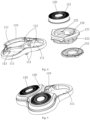
- an embodiment of the present invention provides an inductive shaver, including a shaving head assembly 100 and a handle assembly 200, and the shaving head assembly 100 is mounted on the handle assembly 200.
- the shaving head assembly 100 includes a head cover 110, a holder 120 mounted on the head cover 110, a cutting unit 130 mounted on the holder 120, and a connecting seat 170 for connecting with the handle assembly 200.
- the connecting seat 170 is electrically connected with the holder 120.
- the cutting unit 130 includes cutters 131 mounted on the holder 120 and a rotating cutter head 132 arranged in the cutters 131 and used for cutting. The cutters 131 are in contact with the holder 120 so that the two are electrically connected.
- the holder 120 or the cutters 131 is served as the first end of the first conductive path 300, and the first conductive path 300 is used to receive a first inductive capacitor Cf1 between holder 120 (or the cutters 131) and the ground (GND) when the holder 120 (or the cutters 131) approaches of contacts the human skin 1.
- the handle assembly 200 includes a casing 201, a motor 202 mounted in the casing 201 and used to provide power to the rotating cutter head 132, and a circuit board assembly 210 mounted in the casing 201.
- the circuit board assembly 210 is electrically connected to the second end of the first conductive path 300 and is used to activate the motor 202 when receiving the first inductive capacitor Cf1.
- the holder 120 When shaving, the holder 120 (or the cutters 131) is arranged approaching the human skin 1 such as the chin and cheeks; because the human skin 1 has a certain electric charge, when the human skin 1 directly contacts or approaches the holder 120 (or the cutters 131), the holder 120 (or the cutters 131) will absorb human skin capacitance formed between the approaching position and the ground, which is the first inductive capacitor Cf1.
- the motor 202 When the circuit board assembly 210 receives the first inductive capacitor Cf1, the motor 202 is activated to drive the rotating cutter head 132 in the cutting unit 130 to rotate, so as to achieve the purpose of inductive shaving and ensure long-term reliable use of the shaver.
- the circuit board assembly 210 receives the change signal of the first inductive capacitor Cf1, and at this time, the motor 202 is activated.
- an embodiment of the present invention provides a shaving head assembly 100, which includes a head cover 110, a holder 120 mounted on the head cover 110, a cutting unit 130 mounted on the holder 120, and a connecting seat 170 configured for connecting the handle assembly 200.
- the connecting seat 170 is electrically connected with the holder 120, the holder 120 (or the cutters 131) is served as the first end of the first conductive path 300, and the first conductive path 300 is used to receive the first inductive capacitor Cf1 between the holder 120 (or the cutters 131) and the ground (GND) when the holder 120 (or the cutters 131) approaches or contacts the human skin 1.
- the connecting seat 170 is electrically connected with the holder 120.
- the holder 120 (or the cutters 131) serves as the first end of the first conductive path 300.
- the holder 120 (or the cutters 131) is arranged approaching the human skin 1 such as the chin and cheeks; because the human skin 1 has a certain electric charge, when the human skin 1 directly contacts or approaches the holder 120 (or the cutters 131), the holder 120 (or the cutters 131) will absorb human skin capacitance formed between the approaching position and the ground, which is the first inductive capacitor Cf1, and the signal of the first inductive capacitor Cf1 is served as the signal to activate the motor 202.
- the holder 120 when the holder 120 or the cutters 131 is (are) served as the first end of the first conductive path 300, the holder 120 is a conductor. It is easy to process the holder 120 by directly using the conductive material. Alternatively, the outer surface of the holder 120 is provided with a conductive layer. By arranging the holder 120 formed by the conductive layer on the outer surface of the plastic member, the weight will be lighter. Similarly, when the cutters 131 are served as the first end of the first conductive path 300, the cutters 131 are conductors. Alternatively, the outer surfaces of the cutters 131 are provided with a conductive layer. Both fabrication methods can be served as the first end of the first conductive path 300, and the holder 120 (or the cutters 131) will absorb the human skin capacitance formed between it and the ground from a position approaching the human skin 1.
- the holder 120 is provided with a mounting groove 121, the cutting unit 130 is penetrated through the mounting groove 121 and arranged in the mounting groove 121, and the holder 120 is mounted with a fixing plate 133 for limiting the cutting unit 130.
- the assembly is simple. Specifically, the cutting unit 130 is inserted into the mounting groove 121 of the holder 120 from bottom to top, and is limited by the bottom edge of the cutting unit 130 to fix the fixing plate 133 on the inner wall of the holder 120.
- the holder 120 and the head cover 110 are abutted against each other so that the both are electrically connected and serve as a part of the first conductive path 300.
- the head cover 110 is provided with a mounting hole 111, and the holder 120 is swingably disposed in the mounting hole 111.
- the holder 120 is swingably arranged on the head cover 110, so that the angle of the holder 120 can be automatically adjusted to fit the human skin 1 during shaving, which provides comfort and better shaving experience.
- the holder 120 is assembled on the head cover 110 by swinging a positioning shaft 112 on the head cover 110, and the positioning shaft 112 is inserted into the connecting hole 122 of the holder 120 to realize the movable mounting of the holder 120 on the head cover 110.
- the holders 120 are provided with three, the three holders 120 are distributed in a circumferential direction, and the three holders 120 are distributed in a triangle relative to the swing axis of the head cover 110.
- the relative area with the human skin 1 can be increased, and when the user brings the holder 120 (or the cutters 131) approaching the human skin 1, the holder 120 (or the cutters 131) can more easily absorb the human skin capacitance formed between the approaching position to the human skin 1 and the ground, and then transmitted to the circuit board assembly 210.
- a gear transmission mechanism is provided between the motor 202 and the shaving head assembly 100, and the gear transmission mechanism includes a driving gear 142 and a driven gear 143 meshed with the driving gear 142, and the driven gear 143 is connected with a connecting shaft 144.
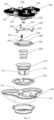
- the shaving head assembly 100 further includes a gear frame 140 aligned with the head cover 110, a cover plate 150 mounted on one end of the gear frame 140, and a snap-fit member 150 mounted on the cover plate 150 and engaged with the head cover 110, the snap-fit member 150 is configured to connect the head cover 110 and the cover plate 150.
- the motor 202 of the handle assembly 200 drives the driving gear 142 to rotate.
- the driven gear 143 is rotatably disposed on the gear frame 140, and the connecting shaft 144 of the driven gear 143 passes through the cover plate 150 and is connected to the rotating cutter head 132 of the cutting unit 130 to drive the rotating cutter head 132 to rotate.
- the head cover 110 abuts against the snap-fit member 150 for electrical connection and serves as a part of the first conductive path 300.
- the middle part of the cover plate 150 is provided with a positioning post 151, and the snap-fit member 150 is provided with a positioning hole 161 through which the positioning post 151 passes.
- the snap-fit member 150 is provided with several positioning buckles 162 circumferentially distributed, and the cover plate 150 is provided with insertion holes 152 for the positioning buckles 162 to insert.
- the positioning hole 161 is aligned with the positioning post 151 at the bottom of the cover plate 150 and then sleeved on the positioning post 151, then the positioning hole 161 is inserted into the insertion hole 152, and then the snap-fit member 150 can be assembled on the cover plate 150, the connection is reliable and stable.
- the shaving head assembly 100 further includes a floating pressing plate 180 disposed in the gear frame 140, and a floating elastic member 190 with two ends respectively abutting on the connecting seat 170 and the floating pressing plate 180.
- the configuration of the connecting seat 170, the floating pressing plate 180 and the floating elastic member 190 can make the cutting unit 130 move in the axial direction, thereby improving the shaving experience of the user.
- the snap-fit member 150 and the floating pressing plate 180 are electrically connected through the first conductor 101.
- the floating pressing plate 180, the floating elastic member 190, and the connecting seat 170 are electrically connected in sequence and serve as a part of the first conductive path 300.
- the snap-fit member 150, the first conductor 101, the floating pressing plate 180, the floating elastic member 190, and the connecting seat 170 are electrically connected in sequence, and the human skin capacitance between the holder 120 (or the cutters 131) and the ground is transmitted to the circuit board assembly 210 in the handle assembly 200.
- the outer edge of the floating pressing plate 180 is provided with a limiting structure 181
- the floating pressing plates 180 are fixed together by the positioning grooves 141 on the gear frame 140, and the limiting structure 181 can be engaged in the positioning groove 141.
- a trim ring pressing plate 102 is assembled on the gear frame 140 by the positioning fit of the connecting seat 170, and then being assembled together with floating elastic member 190 and the floating pressing plate 180 by the connecting seat 170.
- the floating pressing plate 180 is provided with a connecting post 182, the first conductor 101 is elastic members, one end of the first conductor 101 is sleeved on the connecting post 182, and the other end of the first conductor 101 is abutted on the connecting post 182.
- the elastic first conductor 101 By using the elastic first conductor 101, the reliable electrical connection between the floating pressing plate 180 and the snap-fit member 150 can be ensured.
- the first conductor 101 is positioned and assembled on the floating pressing plate 180 by using the connecting post 182, so that the connection between the first conductor 101 and the floating pressing plate 180 is reliable.
- the connecting seat 170 is provided with a mounting cavity 171
- the inner wall of the connecting seat 170 is provided with a first positioning boss 172
- the floating pressing plate 180 is provided with a second positioning boss 183
- two ends of the floating elastic member 190 are respectively sleeved on the first positioning boss 172 and the second positioning boss 183.
- a plurality of buckles 113 are provided on the head cover 110, and the buckles 113 of the head cover 110 are aligned with the insertion holes 152 on the cover plate 150, and the buckles 113 are tightly combined with the positioning buckles 162 of the snap-fit member 150 to achieve a detachable fit between the head cover 110 and the cover plate 150.
- an embodiment of the present invention provides a handle assembly 200, and the handle assembly 200 is configured to connect the above-mentioned shaving head assembly 100.
- the handle assembly 200 includes a casing 201, a motor 202 mounted in the casing 201 and used to power the cutting unit 130, and a circuit board assembly 210 mounted in the casing 201.
- the circuit board assembly 210 is electrically connected to the second end of the first conductive path 300, and is configured for activating the motor 202 when receiving the first inductive capacitor Cf1.
- the circuit board assembly 210 is electrically connected to the second end of the first conductive path 300.
- the motor 202 is activated to drive the rotating cutter head 132 in the cutting unit 130 to rotate.
- the circuit board assembly 210 is provided with a first receiving end 211a that is electrically connected to the second end of the first conductive path 300 to receive the first inductive capacitor Cf1, and the circuit board assembly 210 is provided with a first capacitor 212 electrically connected to the first receiving end 211a and used for determining the reference capacitor Cp1, the circuit board assembly 210 includes a controller 213 for activating the motor 202 when the first receiving end 211a obtains the first inductive capacitor Cf1.
- the first inductive capacitor Cf1 and the reference capacitor Cp1 are connected in parallel to the first receiving end 211a.
- the first inductive capacitor Cf1 When there is no human skin 1 approaching the holder 120 (or cutters 131), there is no the first inductive capacitor Cf1 formed between the human skin 1 and the ground, only the reference capacitor Cp1 on the circuit board assembly 210; when there is human skin 1 approaching the holder 120 (or cutters 131), the first inductive capacitor Cf1 is formed between the holder 120 (or cutters 131) and the ground. Since Cf1 and Cp1 are connected in parallel, before and after the human skin 1 approaches the holder 120 (or the cutters 131), the total capacitor produces a capacitance change after entering the first receiving end 211 a. That is, when the first receiving end 211a obtains the change signal of the first inductive capacitor Cf1, the controller 213 activates the motor 202 to drive the rotating cutter head 132 in the cutting unit 130 to rotate.
- the handle assembly 200 further includes an upper cover 220 mounted at an end port of the casing 201, and the upper cover 220 has an insertion slot 221 for the connecting seat 170 to be inserted, the connecting seat 170 is detachably mounted on the upper cover 220, and the connecting seat 170 is electrically connected with the upper cover 220 as a part of the first conductive path 300.
- the structure in which the connecting seat 170 is detachably mounted on the upper cover 220 is adopted, so that the shaving head assembly 100 can be easily disassembled for cleaning.
- a side wall of the insertion slot 221 is provided with a through hole 223, and the handle assembly 200 further includes a latch fastener 230 penetrated through the through hole 223 and elastic members 231 configured for pushing the latch fastener 230, referring to Fig. 6 together, the connecting seat 170 is provided with a latching position 173 for the latch fastener 230 to be engaged into.
- the latch fastener 230 is engaged into the latching position 173 of the connecting seat 170 to lock the connecting seat 170 on the upper cover 220.
- Disassembly is accomplished by pulling out the handle assembly 200.
- the assembly and disassembly are very convenient.
- the connecting seat 170 is mounted on the upper cover 220, the connecting seat 170 is abutted on the upper cover 220 to be electrically connected, and the upper cover 220, the latch fastener 230, and the elastic member 231 are electrically connected in sequence and serve as a part of the first conductive path 300.
- the human skin capacitance is transmitted to the inside of the handle assembly 200.
- the handle assembly 200 further includes an inner shell 203 mounted in the casing 201, a second conductor 204 mounted on the inner shell 203, and a third conductor 205 mounted on the inner shell 203 and is electrically connected to the second conductor 204.
- the circuit board assembly 210 is mounted on the inner shell 203.
- the second conductor 204 is abutted on one of the elastic members 231, and the third conductor 205 is electrically connected to the first receiving end 211a.
- the third conductor 205 may be assembled to the inner shell 203 by riveting or other mechanical connection.
- the use of the inner shell 203 facilitates the assembly of devices such as the circuit board assembly 210.
- the signal is transmitted to the first receiving end 211a through the second conductor 204 and the third conductor 205, and the assembly is convenient and the structure is compact.
- the second conductor 204 is disposed on the upper surface of the upper end platform 2031 of the inner shell 203;
- the third conductor 205 is strip-shaped and disposed on the outer surface of the inner shell 203, and one end of the third conductor 205 is located on the lower surface of the upper end platform 2031 of the inner shell 203;
- the second conductor 204 and the third conductor 205 are respectively provided with a round hole, and the screws 206 pass through the round hole of the second conductor 204, the round hole of the upper end platform 2031, and the round hole of the third conductor 205, to fixedly connect the third conductor 205, the inner shell 203, and the second conductor 204.
- the second conductor 204 and the third conductor 205 are electrically connected by screws 206 passing through the inner shell 203.
- the fixing buckle 222 of the upper cover 220 is assembled together with the engagement hole 2032 on the top edge of the inner shell 203, so that one of the elastic members 231 is connected to the second conductor 204.
- the first conductive path 300 of the inductive shaver passes through the holder 120, the head cover 110, the snap-fit member 150, the first conductor 101, the floating pressing plate 180, the floating elastic member 190, the connecting seat 170, the upper cover 220, the latch fastener 230, the elastic member 231, the second conductor 204, the screws 206, and the third conductor 205 and finally transmitted to the first receiving end 211a of the circuit board assembly 210.
- the first conductive path 300 of the inductive shaver passes through the cutters 131, the holder 120, the head cover 110, the snap-fit member 150, the first conductor 101, the floating pressing plate 180, the floating elastic member 190, the connecting seat 170, the upper cover 220, the latch fastener 230, the elastic member 231, the second conductor 204, the screws 206, and the third conductor 205 and finally transmitted to the first receiving end 211a of circuit board assembly 210.
- the surfaces of the above parts are treated with a conductive coating to achieve a conductive state, and are assembled into a complete first conductive path 300 through structural cooperation between the parts.
- the circuit board assembly 210 further includes a touch signal processor 211, the first receiving end 211 a is arranged on the touch signal processor 211, and the controller 213 is electrically connected with the touch signal processor 211.
- the touch signal processor 211 belongs to the prior art, and the touch signal processor 211 can receive electrical signals, determine the magnitude of the capacitance change, and then output a trigger signal to the controller 213.
- a touch signal processor 211 with a model of ASC8022S or BS83A02C can be used.
- This total capacitance change causes the change of the internal oscillation frequency or charging and discharging time of the touch signal processor 211, so that the touch signal processor 211 can detect the touch signal TI, and the touch signal processor 211 thus generates the trigger signal TO (touch output level signal) to the controller 213; when there is no touching or approaching, TO has no valid signal outputting.
- the controller 213 detects a valid signal TO, the controller 213 outputs relevant signals to the motor 202 through an internal interrupt processing, thereby, the motor is controlled to rotate and then to rotate the rotating cutter head 132 in the cutting unit 130.
- the controller 213 is connected to the power source 214 to power the various devices.
- the power source 214 can be a battery provided within the casing 201.
- the handle assembly 200 further includes a wake-up sensor for switching the motor 202 to a standby state.
- the arrangement of the wake-up sensor can avoid the situation that only the first conductive path 300 is provided and the motor 202 will be activated by mistake.
- the motor 202 When in use, the motor 202 must be in the standby state by the wake-up sensor first, and then the first conductive path 300 can realize the induction of the human skin 1 approaching the holder 120 (or the cutters 131) to activate the motor 202.
- the casing 201 is a conductive casing; the circuit board assembly 210 is provided with a second receiving end 211b configured for receiving a second inductive capacitor Cf2 between the casing 201 and the ground (GND) when the casing 201 approaches or contacts the human skin 1' (hand), the circuit board assembly 210 is provided with a second capacitor 215 that is electrically connected to the second receiving end 211b and configured for determining a reference capacitor Cp2; the controller 213 is also configured for controlling the motor 202 being in a standby state When the second receiving end 211b obtains the second inductive capacitor Cf2; the wake-up sensor includes a second conductive path 400, the casing 201 is served as the first end of the second conductive path 400, and the second end of the second conductive path 400 is electrically connected to the second receiving end 211b.
- the casing 201 of the handle assembly 200 When in used, the casing 201 of the handle assembly 200 is held by hand firstly, and due that the human skin 1' (hand) has a certain electric charge, when the human skin 1' directly touches or approaches the conductive casing 201, the casing 201 absorbs the human skin capacitance between the approaching or contacting position and the ground, that is, the second inductive capacitor Cf2.
- the second sensing capacitor Cf2 and the reference capacitor Cp2 are connected in parallel to the second receiving end 211b, and when the second receiving end 211b obtains the second inductive capacitor Cf2, the controller 213 wakes up the motor 202 to switch to the standby state.
- the second receiving end 211b is provided on the above-mentioned touch signal processor 211, and the connection between the second conductive path 400, the second capacitor 215 and the second receiving end 211b is similar to that of the first conductive path 300, the first capacitor 212 and the first receiving end 211a.
- the second inductive capacitor Cf2 when there is no human skin 1' (hand) approaching the casing 201, there is no second inductive capacitor Cf2 between the human skin 1' and the ground, and only the reference capacitor Cp2 on the circuit board assembly 210; when there is human skin 1 ' approaching the casing 201, the second inductive capacitor Cf2 is formed between the casing 201 and the ground. Since Cf2 and Cp2 are connected in parallel, before and after the human skin 1' approaches the casing 201, the total capacitance produces a capacitance change after entering the second receiving end 211b. That is, the second receiving end 211b obtains the change signal of the second sensing capacitor Cf2, and at this time, the controller 213 controls the motor 202 in a standby state.
- the handle assembly 200 further includes an inner shell 203 mounted in the casing 201 and a fourth conductor 207 mounted on the inner shell 203.
- One end of the fourth conductor 207 is abutted on the casing 201, and the other end is electrically connected to the second receiving end 211b.
- the fourth conductor 207 is configured to realize the electrical connection between the second receiving end 211b and the casing 201. After the human hand holds the casing 201, the signal of the second sensing capacitor Cf2 can be reliably transmitted to the second receiving end 211b.
- the fourth conductor 207 may be an elastic bending member, and one end of the bending member is abutted on the inner wall of the casing 201 to achieve stable electrical connection between the casing 201 and the fourth conductor 207.
- the fourth conductor 207 can be mounted on the inner shell by riveting or other mechanical connection.
Landscapes
- Life Sciences & Earth Sciences (AREA)
- Forests & Forestry (AREA)
- Engineering & Computer Science (AREA)
- Mechanical Engineering (AREA)
- Dry Shavers And Clippers (AREA)
Claims (18)
- Eine Rasierkopfanordnung (100), das Folgende umfasst:einen Kopfdeckel (110);einen Halter (120), der auf dem Kopfdeckel (110) montiert ist;eine Schneideeinheit (130), die auf dem Halter (120) montiert ist, wobei die Schneideeinheit (130) Schneideelemente (131), die auf dem Halter (120) montiert sind, sowie einen rotierenden Schneidkopf (132), der in den Schneideelementen (131) angeordnet ist, umfasst; undeinen Verbindungssockel (170), der zum Anschluss an eine Handgriffanordnung (200) ausgebildet ist, wobei der Verbindungssockel (170) elektrisch mit dem Halter (120) verbunden ist.wobei der Halter (120) als ein erstes Ende eines ersten leitfähigen Pfades (300) angeordnet ist, und wobei der erste leitfähige Pfad (300) so ausgestaltet ist, dass ein erster induktiver Kondensator (Cf1) zwischen dem Halter (120) und der Masse aufgenommen werden kann, wenn sich der Halter (120) der menschlichen Haut (1) annähert oder diese berührt; oderwobei die Schneideelemente (131) als ein erstes Ende eines ersten leitfähigen Pfades (300) dienen, und wobei der erste leitfähige Pfad (300) so ausgestaltet ist, dass ein erster induktiver Kondensator (Cf1) zwischen den Schneideelementen (131) und der Masse aufgenommen werden kann, wenn sich die Schneideelemente (131) der menschlichen Haut (1) annähern oder diese berühren;wobei die Rasierkopfanordnung (100) ferner ein Zahnradgestell (140) umfasst, das mit dem Kopfdeckel (110) ausgerichtet ist, eine Abdeckplatte (150), die an einem Ende des Zahnradgestells (140) montiert ist, und ein Schnappverschluss-Element (160), das an der Abdeckplatte (150) montiert ist und mit dem Kopfdeckel (110) in Eingriff steht; der Kopfdeckel (110) ist elektrisch mit dem Schnappverschluss-Element (160) verbunden und dient als Teil des ersten leitfähigen Pfades (300);wobei die Rasierkopfanordnung (100) ferner eine schwebende Druckplatte (180) umfasst, die im Zahnradgestell (140) angeordnet ist, und ein schwebendes elastisches Element (190), dessen zwei Enden jeweils gegen den Verbindungssockel (170) und die schwebende Druckplatte (180) anstoßen, wobei das Schnappverschluss-Element (160) und die schwebende Druckplatte (180) elektrisch über einen ersten Leiter verbunden sind, und wobei die schwebende Druckplatte (180), das schwebende elastische Element (190) und der Verbindungssockel (170) in Reihe elektrisch verbunden sind und als Teil des ersten leitfähigen Pfades (300) dienen.
- Die Rasierkopfanordnung (100) gemäß Anspruch 1, wobei, wenn der Halter (120) als das erste Ende des ersten leitfähigen Pfades (300) dient, der Halter (120) als Leiter ausgebildet ist; oder eine äußere Oberfläche des Halters (120) mit einer leitfähigen Schicht versehen ist; und
wobei, wenn die Schneideelemente (131) als das erste Ende des ersten leitfähigen Pfades (300) dienen, die Schneideelemente (131) als Leiter ausgebildet sind; oder eine äußere Oberfläche der Schneideelemente (131) mit einer leitfähigen Schicht versehen ist. - Die Rasierkopfanordnung (100) gemäß Anspruch 1, wobei der Halter (120) mit einer Montierungsnut (121) versehen ist, die Schneideeinheit (130) in der Montierungsnut (121) angeordnet ist, der Halter (120) mit einer Fixierplatte (133) montiert ist, die zum Begrenzen der Schneideeinheit (130) ausgebildet ist, und der Halter (120) elektrisch mit dem Kopfdeckel (110) verbunden ist und als Teil des ersten leitfähigen Pfades (300) dient.
- Die Rasierkopfanordnung (100) gemäß Anspruch 3, wobei der Kopfdeckel (110) mit einem Montierungsloch (111) versehen ist, und der Halter (120) schwenkbar im Montierungsloch (111) angeordnet ist.
- Die Rasierkopfanordnung (100) gemäß Anspruch 1, wobei im Mittelteil der Abdeckplatte (150) ein Positionierstift (151) vorgesehen ist, das Schnappverschluss-Element (160) mit einem Positionierloch (161) versehen ist, das für das Durchführen des Positionierstifts (151) ausgebildet ist; das Schnappverschluss-Element (160) mit einer Vielzahl von positionierenden Riegeln (162) versehen ist, die umlaufend verteilt sind, und die Abdeckplatte (150) mit Einfühlöffnungen (152) versehen ist, die so ausgebildet sind, dass die positionierenden Riegel (162) eingeführt werden können.
- Die Rasierkopfanordnung (100) gemäß Anspruch 1, wobei die schwebende Druckplatte (180) mit einem Verbindungspfosten (182) versehen ist, der erste Leiter elastische Elemente umfasst, wobei ein Ende des ersten Leiters als Hülse um den Verbindungspfosten (182) eingesetzt ist und das andere Ende des ersten Leiters an das Schnappverschluss-Element (160) anstößt.
- Die Rasierkopfanordnung (100) gemäß Anspruch 1, wobei der Verbindungssockel (170) mit einer Montierungsöffnung (171) versehen ist, die Innenwand des Verbindungssockels (170) mit einem ersten Positionierboss (172) versehen ist, und die schwebende Druckplatte (180) mit einem zweiten Positionierboss (183) versehen ist, wobei die beiden Enden des schwebenden elastischen Elements (190) jeweils als Hülse um den ersten Positionierboss (172) und den zweiten Positionierboss (183) eingesetzt sind.
- Eine Handgriffanordnung (200), die zum Anschluss an die Rasierkopfanordnung (100) gemäß einem der Ansprüche 1 bis 7 ausgebildet ist, umfassend:ein Gehäuse (201);einen Motor (202), der im Gehäuse (201) montiert ist und zum Betreiben des rotierenden Schneidkopfs (132) ausgebildet ist; undeine Leiterplattenanordnung (210), die im Gehäuse (201) montiert ist;wobei die Leiterplattenanordnung (210) elektrisch mit einem zweiten Ende des ersten leitfähigen Pfades (300) verbunden ist und zum Aktivieren des Motors (202) ausgebildet ist, wenn der erste induktive Kondensator (Cf1) empfangen wird.
- Die Handgriffanordnung (200) gemäß Anspruch 8, wobei die Leiterplattenanordnung (210) mit einem ersten Empfangsende (211a) versehen ist, das elektrisch mit dem zweiten Ende des ersten leitfähigen Pfades (300) verbunden ist, um den ersten induktiven Kondensator (Cf1) zu empfangen, wobei die Leiterplattenanordnung (210) mit einem ersten Kondensator versehen ist, der elektrisch mit dem ersten Empfangsende (211a) verbunden ist und dazu ausgebildet ist, einen Referenzkondensator (Cp1) zu bestimmen, wobei die Leiterplattenanordnung (210) einen Controller (213) umfasst, der zum Aktivieren des Motors (202) ausgebildet ist, wenn das erste Empfangsende (211a) den ersten induktiven Kondensator (Cf1) erhält.
- Die Handgriffanordnung (200) gemäß Anspruch 9, wobei die Handgriffanordnung (200) ferner einen oberen Deckel (220) umfasst, der an einem Endanschluss des Gehäuses (201) montiert ist, wobei der obere Deckel (220) mit einem Einfüge-Slot (221) versehen ist, der so ausgebildet ist, dass der Verbindungssockel (170) eingeführt werden kann, wobei der Verbindungssockel (170) abnehmbar am oberen Deckel (220) montiert ist, und wobei der Verbindungssockel (170) elektrisch mit dem oberen Deckel (220) verbunden ist und als Teil des ersten leitfähigen Pfades (300) dient.
- Die Handgriffanordnung (200) gemäß Anspruch 10, wobei eine Seitenwand des Einfüge-Slots (221) mit einem Durchgangsloch (223) versehen ist, und wobei die Handgriffanordnung (200) ferner einen Riegelverschluss (230) umfasst, der durch das Durchgangsloch (223) hindurchgeht, und elastische Elemente (231), die zum Drücken des Riegelverschlusses (230) ausgebildet sind, wobei der Verbindungssockel (170) ferner mit einer Verriegelungsposition versehen ist, in die der Riegelverschluss (230) eingreifen kann, und wobei der obere Deckel (220), der Riegelverschluss (230) und die elastischen Elemente (231) in Reihe elektrisch verbunden sind und als Teil des ersten leitfähigen Pfades (300) dienen.
- Die Handgriffanordnung (200) gemäß Anspruch 11, wobei die Handgriffanordnung (200) ferner eine Innenschale (203) umfasst, die im Gehäuse (201) montiert ist, einen zweiten Leiter (204), der auf der Innenschale (203) montiert ist, und einen dritten Leiter (205), der auf der Innenschale (203) montiert ist und elektrisch mit dem zweiten Leiter (204) verbunden ist, wobei die Leiterplattenanordnung (210) auf der Innenschale (203) montiert ist, der zweite Leiter (204) an einem der elastischen Elemente (231) anstößt und der dritte Leiter (205) elektrisch mit dem ersten Empfangsende (211a) verbunden ist.
- Die Handgriffanordnung (200) gemäß Anspruch 12, wobei der zweite Leiter (204) an einem oberen Ende der Innenschale (203) angeordnet ist; der dritte Leiter (205) streifenförmig ist und an der Außenseite der Innenschale (203) angeordnet ist; der zweite Leiter (204) und der dritte Leiter (205) elektrisch durch Schrauben verbunden sind, die durch die Innenschale (203) hindurchgehen.
- Die Handgriffanordnung (200) gemäß einem der Ansprüche 9 bis 11, wobei die Handgriffanordnung (200) ferner einen Wecksensor umfasst, der den Motor (202) in einen Bereitschaftszustand versetzt.
- Die Handgriffanordnung (200) gemäß Anspruch 14, wobei das Gehäuse (201) ein leitfähiges Gehäuse (201) ist; die Leiterplattenanordnung (210) mit einem zweiten Empfangsende (211b) versehen ist, das dazu ausgebildet ist, einen zweiten induktiven Kondensator (Cf2) zwischen dem Gehäuse (201) und dem Erdreich zu empfangen, wenn das Gehäuse (201) sich der menschlichen Haut (1) nähert oder mit dieser in Kontakt kommt, wobei die Leiterplattenanordnung (210) mit einem zweiten Kondensator versehen ist, der elektrisch mit dem zweiten Empfangsende (211b) verbunden ist und dazu ausgebildet ist, einen Referenzkondensator (Cp2) zu bestimmen; und der Controller (213) ferner dazu ausgebildet ist, den Motor (202) im Bereitschaftszustand zu halten, wenn das zweite Empfangsende (211b) den zweiten induktiven Kondensator (Cf2) erhält; und
der Wecksensor einen zweiten leitfähigen Pfad (400) umfasst, wobei das Gehäuse (201) als erstes Ende des zweiten leitfähigen Pfades (400) dient und das zweite Ende des zweiten leitfähigen Pfades (400) elektrisch mit dem zweiten Empfangsende (211b) verbunden ist. - Die Handgriffanordnung (200) gemäß Anspruch 15, wobei die Handgriffanordnung (200) ferner eine Innenschale (203) umfasst, die im Gehäuse (201) montiert ist, und einen vierten Leiter (207), der auf der Innenschale (203) montiert ist, wobei ein Ende des vierten Leiters (207) an das Gehäuse (201) anstößt und das andere Ende elektrisch mit dem zweiten Empfangsende (211b) verbunden ist.
- Die Handgriffanordnung (200) gemäß Anspruch 15, wobei die Leiterplattenanordnung (210) ferner einen Touch-Signalprozessor umfasst, wobei das erste Empfangsende (211a) und das zweite Empfangsende (211b) beide auf dem Touch-Signalprozessor angeordnet sind und der Controller (213) elektrisch mit dem Touch-Signalprozessor verbunden ist.
- Ein induktiver Rasierer, umfassend die Rasierkopfanordnung (100) gemäß einem der Ansprüche 1 bis 7 und die Handgriffanordnung (200) gemäß einem der Ansprüche 8 bis 17, wobei die Rasierkopfanordnung (100) mit der Handgriffanordnung (200) verbunden ist.
Applications Claiming Priority (2)
| Application Number | Priority Date | Filing Date | Title |
|---|---|---|---|
| CN201911118874.6A CN110802640B (zh) | 2019-11-15 | 2019-11-15 | 刀头组件、手柄组件及感应式剃须刀 |
| PCT/CN2020/128545 WO2021093833A1 (zh) | 2019-11-15 | 2020-11-13 | 刀头组件、手柄组件及感应式剃须刀 |
Publications (3)
| Publication Number | Publication Date |
|---|---|
| EP4059674A1 EP4059674A1 (de) | 2022-09-21 |
| EP4059674A4 EP4059674A4 (de) | 2023-01-25 |
| EP4059674B1 true EP4059674B1 (de) | 2025-06-04 |
Family
ID=69490150
Family Applications (1)
| Application Number | Title | Priority Date | Filing Date |
|---|---|---|---|
| EP20886994.1A Active EP4059674B1 (de) | 2019-11-15 | 2020-11-13 | Klingenanordnung, griffanordnung und induktionsrasierer |
Country Status (5)
| Country | Link |
|---|---|
| US (1) | US20220395994A1 (de) |
| EP (1) | EP4059674B1 (de) |
| KR (1) | KR102851443B1 (de) |
| CN (1) | CN110802640B (de) |
| WO (1) | WO2021093833A1 (de) |
Families Citing this family (15)
| Publication number | Priority date | Publication date | Assignee | Title |
|---|---|---|---|---|
| CN110802641B (zh) * | 2019-11-15 | 2025-06-03 | 深圳素士科技股份有限公司 | 刀头组件及包含该刀头组件的剃须器 |
| CN110802640B (zh) * | 2019-11-15 | 2025-06-03 | 深圳素士科技股份有限公司 | 刀头组件、手柄组件及感应式剃须刀 |
| CN110802639B (zh) * | 2019-11-15 | 2025-06-03 | 深圳素士科技股份有限公司 | 刀头组件及具有该刀头组件的剃须装置 |
| EP3825078A1 (de) * | 2019-11-19 | 2021-05-26 | Koninklijke Philips N.V. | Rasiereinheit und elektrischer rasierer mit der rasiereinheit |
| CN112060136B (zh) * | 2020-07-01 | 2022-06-21 | 深圳素士科技股份有限公司 | 刀头组件、齿轮仓以及浮动剃须刀 |
| CN111941469A (zh) * | 2020-09-03 | 2020-11-17 | 上海飞科电器股份有限公司 | 剃刀刀头及电动剃刀 |
| CN112571461B (zh) * | 2020-12-07 | 2022-04-12 | 深圳素士科技股份有限公司 | 一种感应区间的校准方法、校准装置、感应剃须刀及介质 |
| CN113715064B (zh) * | 2021-08-02 | 2023-01-13 | 利民(番禺南沙)电器发展有限公司 | 一种旋转式剃须刀 |
| CN113878619B (zh) * | 2021-11-12 | 2023-04-11 | 蓓慈电器有限公司 | 一种剃须刀头部浮动结构及剃须刀 |
| CN114654508A (zh) * | 2022-04-21 | 2022-06-24 | 慈溪市金悦电子有限公司 | 一种剃须刀 |
| CN115008507B (zh) * | 2022-06-06 | 2024-04-19 | 江苏百特电器有限公司 | 一种刀架及剃须刀 |
| CN115179331A (zh) * | 2022-07-01 | 2022-10-14 | 夏小军 | 一种手持感应式剃须刀 |
| CN115814274A (zh) * | 2022-12-09 | 2023-03-21 | 北京冠舟科技有限公司 | 一种美容射频头 |
| CN117245699B (zh) * | 2023-10-24 | 2025-10-10 | 浙江志伯电器科技有限公司 | 一种感应剃须刀机头插拔浮动装置 |
| EP4606538A1 (de) * | 2024-02-21 | 2025-08-27 | Koninklijke Philips N.V. | Verwendung von kopplungselementen zur lösbaren kopplung von komponenten einer körperpflegevorrichtung |
Family Cites Families (29)
| Publication number | Priority date | Publication date | Assignee | Title |
|---|---|---|---|---|
| AT366946B (de) * | 1980-04-03 | 1982-05-25 | Payer Lux Elektroprod | Elektrischer rasierapparat |
| JPS59184778U (ja) * | 1983-05-25 | 1984-12-08 | フイリツプス工業振興株式会社 | 自動動作電気ひげそり器 |
| GB2399045B (en) * | 2003-02-19 | 2005-11-16 | Gillette Co | Safety razors |
| DE602004010269T2 (de) * | 2003-07-23 | 2008-10-02 | Koninklijke Philips Electronics N.V. | Rasiergerät |
| US8196303B2 (en) | 2003-11-25 | 2012-06-12 | Koninklijke Philips Electronics N.V. | Shaving apparatus and method of manufacturing such apparatus |
| GB2419103A (en) * | 2004-10-18 | 2006-04-19 | Gillette Co | Electric razor with pivoting head |
| FR2883219B3 (fr) * | 2005-03-21 | 2007-06-15 | Michel Trezon | Dispositif de rasage manuel pour detruire et couper simultanement les poils |
| JP4438774B2 (ja) * | 2006-07-14 | 2010-03-24 | パナソニック電工株式会社 | シェーバ洗浄装置およびシェーバシステム |
| US20080052911A1 (en) * | 2006-09-01 | 2008-03-06 | Eveready Battery Company, Inc. | Shaving implement and method for using same |
| US8061041B2 (en) * | 2007-02-14 | 2011-11-22 | The Gillette Company | Safety razor |
| US20090049694A1 (en) * | 2007-08-21 | 2009-02-26 | Gary Jay Morris | Electric shaver apparatus with actively cooled surface |
| EP2218559B1 (de) * | 2009-02-13 | 2012-08-15 | Trisa Holding AG | Körperpflegevorrichtung |
| US9027251B2 (en) * | 2009-04-29 | 2015-05-12 | Spectrum Brands, Inc. | Rotary electric shaver |
| JP5424258B2 (ja) | 2010-01-15 | 2014-02-26 | 株式会社泉精器製作所 | 電気かみそり |
| ES2702037T3 (es) * | 2012-03-22 | 2019-02-27 | Koninklijke Philips Nv | Afeitadora que tiene una superficie de acoplamiento con la piel adaptativa |
| US10131061B2 (en) * | 2013-05-30 | 2018-11-20 | Koninklijke Philips N.V. | Device and system for treating hair and/or skin |
| CN203390959U (zh) * | 2013-06-13 | 2014-01-15 | 上海奔腾电工有限公司 | 一种浮动式电动剃须刀 |
| JP6688049B2 (ja) * | 2015-11-24 | 2020-04-28 | マクセルイズミ株式会社 | ロータリー式電気かみそりおよびロータリー式電気かみそりの内刃の製造方法 |
| CN105364949A (zh) * | 2015-11-30 | 2016-03-02 | 浙江美森电器有限公司 | 一种剃须刀刀头及剃须刀 |
| US20170232624A1 (en) * | 2016-02-12 | 2017-08-17 | The King Of Shaves Company Limited | Shaving System |
| CN105729507A (zh) * | 2016-04-25 | 2016-07-06 | 浙江美森电器有限公司 | 一种浮动刀头及剃须刀 |
| EP3300864B1 (de) * | 2016-09-28 | 2021-12-15 | Braun GmbH | Elektrischer rasierapparat |
| CN208575902U (zh) * | 2018-08-14 | 2019-03-05 | 江西省胡一刀实业有限公司 | 一种感应式剃须刀 |
| CN109049016B (zh) | 2018-08-22 | 2024-12-31 | 深圳素士科技股份有限公司 | 刀头连接结构、刀头、手柄及剃须刀 |
| CN110281280A (zh) * | 2019-06-06 | 2019-09-27 | 宁波市戍科电器有限公司 | 电磁感应式控制电路、电动剃须刀及工作方法 |
| CN211362344U (zh) * | 2019-11-15 | 2020-08-28 | 舒可士(深圳)科技有限公司 | 刀头组件、手柄组件及感应式剃须刀 |
| CN110802639B (zh) * | 2019-11-15 | 2025-06-03 | 深圳素士科技股份有限公司 | 刀头组件及具有该刀头组件的剃须装置 |
| CN110802640B (zh) * | 2019-11-15 | 2025-06-03 | 深圳素士科技股份有限公司 | 刀头组件、手柄组件及感应式剃须刀 |
| CN110802641B (zh) * | 2019-11-15 | 2025-06-03 | 深圳素士科技股份有限公司 | 刀头组件及包含该刀头组件的剃须器 |
-
2019
- 2019-11-15 CN CN201911118874.6A patent/CN110802640B/zh active Active
-
2020
- 2020-11-13 US US17/777,223 patent/US20220395994A1/en active Pending
- 2020-11-13 KR KR1020227020417A patent/KR102851443B1/ko active Active
- 2020-11-13 EP EP20886994.1A patent/EP4059674B1/de active Active
- 2020-11-13 WO PCT/CN2020/128545 patent/WO2021093833A1/zh not_active Ceased
Also Published As
| Publication number | Publication date |
|---|---|
| KR102851443B1 (ko) | 2025-08-27 |
| EP4059674A4 (de) | 2023-01-25 |
| US20220395994A1 (en) | 2022-12-15 |
| WO2021093833A1 (zh) | 2021-05-20 |
| EP4059674A1 (de) | 2022-09-21 |
| CN110802640A (zh) | 2020-02-18 |
| KR20220098243A (ko) | 2022-07-11 |
| CN110802640B (zh) | 2025-06-03 |
Similar Documents
| Publication | Publication Date | Title |
|---|---|---|
| EP4059674A1 (de) | Klingenanordnung, griffanordnung und induktionsrasierer | |
| CN110802639A (zh) | 刀头组件及具有该刀头组件的剃须装置 | |
| CN110802641B (zh) | 刀头组件及包含该刀头组件的剃须器 | |
| JPS6213582Y2 (de) | ||
| KR20050100403A (ko) | 안전 면도기 | |
| US12539630B2 (en) | Electric shaver, handheld household electrical appliance, electric shaver system, and control method | |
| EP3915739A1 (de) | Haustierrasierer | |
| CN112060136A (zh) | 刀头组件、齿轮仓以及浮动剃须刀 | |
| CN211362344U (zh) | 刀头组件、手柄组件及感应式剃须刀 | |
| CN211362343U (zh) | 刀头组件及包含该刀头组件的剃须器 | |
| CN211362345U (zh) | 刀头组件及具有该刀头组件的剃须装置 | |
| CN111948961A (zh) | 手持家电设备 | |
| CN217728814U (zh) | 一种手持感应式剃须刀 | |
| KR20250001266U (ko) | 면도기 | |
| CN115179331A (zh) | 一种手持感应式剃须刀 | |
| RU2806871C2 (ru) | Электрическая бритва, ручной бытовой электроприбор, система бритвы и метод управления | |
| CN222644665U (zh) | 触控式剃须刀 | |
| CN220384136U (zh) | 一种切面机 | |
| CN218138192U (zh) | 剃须刀开关结构及剃须刀 | |
| CN217292431U (zh) | 一种带有触摸感应组件的剃毛器 | |
| CN116889238B (zh) | 一种压面机 | |
| CN219926105U (zh) | 一种感应式个人护理器具 | |
| CN112405630A (zh) | 防水的医疗理发剪 | |
| CN119369463A (zh) | 触摸感应剃须刀 | |
| HK40076243A (en) | Electric shaver, handheld household electrical appliance, electric shaver system, and control method |
Legal Events
| Date | Code | Title | Description |
|---|---|---|---|
| STAA | Information on the status of an ep patent application or granted ep patent |
Free format text: STATUS: THE INTERNATIONAL PUBLICATION HAS BEEN MADE |
|
| PUAI | Public reference made under article 153(3) epc to a published international application that has entered the european phase |
Free format text: ORIGINAL CODE: 0009012 |
|
| STAA | Information on the status of an ep patent application or granted ep patent |
Free format text: STATUS: REQUEST FOR EXAMINATION WAS MADE |
|
| 17P | Request for examination filed |
Effective date: 20220527 |
|
| AK | Designated contracting states |
Kind code of ref document: A1 Designated state(s): AL AT BE BG CH CY CZ DE DK EE ES FI FR GB GR HR HU IE IS IT LI LT LU LV MC MK MT NL NO PL PT RO RS SE SI SK SM TR |
|
| A4 | Supplementary search report drawn up and despatched |
Effective date: 20230104 |
|
| RIC1 | Information provided on ipc code assigned before grant |
Ipc: B26B 19/38 20060101ALI20221222BHEP Ipc: B26B 19/14 20060101AFI20221222BHEP |
|
| RAP3 | Party data changed (applicant data changed or rights of an application transferred) |
Owner name: SHENZHEN SOOCAS TECHNOLOGY CO., LTD. |
|
| GRAP | Despatch of communication of intention to grant a patent |
Free format text: ORIGINAL CODE: EPIDOSNIGR1 |
|
| STAA | Information on the status of an ep patent application or granted ep patent |
Free format text: STATUS: GRANT OF PATENT IS INTENDED |
|
| INTG | Intention to grant announced |
Effective date: 20250226 |
|
| GRAS | Grant fee paid |
Free format text: ORIGINAL CODE: EPIDOSNIGR3 |
|
| GRAA | (expected) grant |
Free format text: ORIGINAL CODE: 0009210 |
|
| STAA | Information on the status of an ep patent application or granted ep patent |
Free format text: STATUS: THE PATENT HAS BEEN GRANTED |
|
| AK | Designated contracting states |
Kind code of ref document: B1 Designated state(s): AL AT BE BG CH CY CZ DE DK EE ES FI FR GB GR HR HU IE IS IT LI LT LU LV MC MK MT NL NO PL PT RO RS SE SI SK SM TR |
|
| REG | Reference to a national code |
Ref country code: GB Ref legal event code: FG4D |
|
| REG | Reference to a national code |
Ref country code: CH Ref legal event code: EP |
|
| REG | Reference to a national code |
Ref country code: DE Ref legal event code: R096 Ref document number: 602020052453 Country of ref document: DE |
|
| REG | Reference to a national code |
Ref country code: IE Ref legal event code: FG4D |
|
| REG | Reference to a national code |
Ref country code: NL Ref legal event code: MP Effective date: 20250604 |
|
| PG25 | Lapsed in a contracting state [announced via postgrant information from national office to epo] |
Ref country code: FI Free format text: LAPSE BECAUSE OF FAILURE TO SUBMIT A TRANSLATION OF THE DESCRIPTION OR TO PAY THE FEE WITHIN THE PRESCRIBED TIME-LIMIT Effective date: 20250604 Ref country code: ES Free format text: LAPSE BECAUSE OF FAILURE TO SUBMIT A TRANSLATION OF THE DESCRIPTION OR TO PAY THE FEE WITHIN THE PRESCRIBED TIME-LIMIT Effective date: 20250604 |
|
| REG | Reference to a national code |
Ref country code: LT Ref legal event code: MG9D |
|
| PG25 | Lapsed in a contracting state [announced via postgrant information from national office to epo] |
Ref country code: NO Free format text: LAPSE BECAUSE OF FAILURE TO SUBMIT A TRANSLATION OF THE DESCRIPTION OR TO PAY THE FEE WITHIN THE PRESCRIBED TIME-LIMIT Effective date: 20250904 Ref country code: GR Free format text: LAPSE BECAUSE OF FAILURE TO SUBMIT A TRANSLATION OF THE DESCRIPTION OR TO PAY THE FEE WITHIN THE PRESCRIBED TIME-LIMIT Effective date: 20250905 |
|
| PG25 | Lapsed in a contracting state [announced via postgrant information from national office to epo] |
Ref country code: PL Free format text: LAPSE BECAUSE OF FAILURE TO SUBMIT A TRANSLATION OF THE DESCRIPTION OR TO PAY THE FEE WITHIN THE PRESCRIBED TIME-LIMIT Effective date: 20250604 |
|
| PG25 | Lapsed in a contracting state [announced via postgrant information from national office to epo] |
Ref country code: BG Free format text: LAPSE BECAUSE OF FAILURE TO SUBMIT A TRANSLATION OF THE DESCRIPTION OR TO PAY THE FEE WITHIN THE PRESCRIBED TIME-LIMIT Effective date: 20250604 |
|
| PG25 | Lapsed in a contracting state [announced via postgrant information from national office to epo] |
Ref country code: HR Free format text: LAPSE BECAUSE OF FAILURE TO SUBMIT A TRANSLATION OF THE DESCRIPTION OR TO PAY THE FEE WITHIN THE PRESCRIBED TIME-LIMIT Effective date: 20250604 |
|
| PG25 | Lapsed in a contracting state [announced via postgrant information from national office to epo] |
Ref country code: RS Free format text: LAPSE BECAUSE OF FAILURE TO SUBMIT A TRANSLATION OF THE DESCRIPTION OR TO PAY THE FEE WITHIN THE PRESCRIBED TIME-LIMIT Effective date: 20250904 |
|
| PG25 | Lapsed in a contracting state [announced via postgrant information from national office to epo] |
Ref country code: LV Free format text: LAPSE BECAUSE OF FAILURE TO SUBMIT A TRANSLATION OF THE DESCRIPTION OR TO PAY THE FEE WITHIN THE PRESCRIBED TIME-LIMIT Effective date: 20250604 |
|
| PG25 | Lapsed in a contracting state [announced via postgrant information from national office to epo] |
Ref country code: NL Free format text: LAPSE BECAUSE OF FAILURE TO SUBMIT A TRANSLATION OF THE DESCRIPTION OR TO PAY THE FEE WITHIN THE PRESCRIBED TIME-LIMIT Effective date: 20250604 |
|
| PG25 | Lapsed in a contracting state [announced via postgrant information from national office to epo] |
Ref country code: PT Free format text: LAPSE BECAUSE OF FAILURE TO SUBMIT A TRANSLATION OF THE DESCRIPTION OR TO PAY THE FEE WITHIN THE PRESCRIBED TIME-LIMIT Effective date: 20251006 |
|
| REG | Reference to a national code |
Ref country code: AT Ref legal event code: MK05 Ref document number: 1799933 Country of ref document: AT Kind code of ref document: T Effective date: 20250604 |
|
| PG25 | Lapsed in a contracting state [announced via postgrant information from national office to epo] |
Ref country code: IS Free format text: LAPSE BECAUSE OF FAILURE TO SUBMIT A TRANSLATION OF THE DESCRIPTION OR TO PAY THE FEE WITHIN THE PRESCRIBED TIME-LIMIT Effective date: 20251004 |
|
| PGFP | Annual fee paid to national office [announced via postgrant information from national office to epo] |
Ref country code: DE Payment date: 20251117 Year of fee payment: 6 |
|
| PGFP | Annual fee paid to national office [announced via postgrant information from national office to epo] |
Ref country code: GB Payment date: 20251126 Year of fee payment: 6 |
|
| PG25 | Lapsed in a contracting state [announced via postgrant information from national office to epo] |
Ref country code: AT Free format text: LAPSE BECAUSE OF FAILURE TO SUBMIT A TRANSLATION OF THE DESCRIPTION OR TO PAY THE FEE WITHIN THE PRESCRIBED TIME-LIMIT Effective date: 20250604 Ref country code: SM Free format text: LAPSE BECAUSE OF FAILURE TO SUBMIT A TRANSLATION OF THE DESCRIPTION OR TO PAY THE FEE WITHIN THE PRESCRIBED TIME-LIMIT Effective date: 20250604 |
|
| PGFP | Annual fee paid to national office [announced via postgrant information from national office to epo] |
Ref country code: FR Payment date: 20251127 Year of fee payment: 6 |
|
| PG25 | Lapsed in a contracting state [announced via postgrant information from national office to epo] |
Ref country code: CZ Free format text: LAPSE BECAUSE OF FAILURE TO SUBMIT A TRANSLATION OF THE DESCRIPTION OR TO PAY THE FEE WITHIN THE PRESCRIBED TIME-LIMIT Effective date: 20250604 |
|
| PG25 | Lapsed in a contracting state [announced via postgrant information from national office to epo] |
Ref country code: EE Free format text: LAPSE BECAUSE OF FAILURE TO SUBMIT A TRANSLATION OF THE DESCRIPTION OR TO PAY THE FEE WITHIN THE PRESCRIBED TIME-LIMIT Effective date: 20250604 |
|
| PG25 | Lapsed in a contracting state [announced via postgrant information from national office to epo] |
Ref country code: SK Free format text: LAPSE BECAUSE OF FAILURE TO SUBMIT A TRANSLATION OF THE DESCRIPTION OR TO PAY THE FEE WITHIN THE PRESCRIBED TIME-LIMIT Effective date: 20250604 |
|
| PG25 | Lapsed in a contracting state [announced via postgrant information from national office to epo] |
Ref country code: IT Free format text: LAPSE BECAUSE OF FAILURE TO SUBMIT A TRANSLATION OF THE DESCRIPTION OR TO PAY THE FEE WITHIN THE PRESCRIBED TIME-LIMIT Effective date: 20250604 |
|
| PG25 | Lapsed in a contracting state [announced via postgrant information from national office to epo] |
Ref country code: RO Free format text: LAPSE BECAUSE OF FAILURE TO SUBMIT A TRANSLATION OF THE DESCRIPTION OR TO PAY THE FEE WITHIN THE PRESCRIBED TIME-LIMIT Effective date: 20250604 |
|
| REG | Reference to a national code |
Ref country code: DE Ref legal event code: R097 Ref document number: 602020052453 Country of ref document: DE |
|
| PLBE | No opposition filed within time limit |
Free format text: ORIGINAL CODE: 0009261 |
|
| STAA | Information on the status of an ep patent application or granted ep patent |
Free format text: STATUS: NO OPPOSITION FILED WITHIN TIME LIMIT |
|
| PG25 | Lapsed in a contracting state [announced via postgrant information from national office to epo] |
Ref country code: DK Free format text: LAPSE BECAUSE OF FAILURE TO SUBMIT A TRANSLATION OF THE DESCRIPTION OR TO PAY THE FEE WITHIN THE PRESCRIBED TIME-LIMIT Effective date: 20250604 |
|
| REG | Reference to a national code |
Ref country code: CH Ref legal event code: L10 Free format text: ST27 STATUS EVENT CODE: U-0-0-L10-L00 (AS PROVIDED BY THE NATIONAL OFFICE) Effective date: 20260416 |
|
| 26N | No opposition filed |
Effective date: 20260305 |