EP4059588B1 - Strömungsgleichrichter, hydrolyseanlage und denitrifikationsanlage - Google Patents
Strömungsgleichrichter, hydrolyseanlage und denitrifikationsanlage Download PDFInfo
- Publication number
- EP4059588B1 EP4059588B1 EP20888646.5A EP20888646A EP4059588B1 EP 4059588 B1 EP4059588 B1 EP 4059588B1 EP 20888646 A EP20888646 A EP 20888646A EP 4059588 B1 EP4059588 B1 EP 4059588B1
- Authority
- EP
- European Patent Office
- Prior art keywords
- straightening device
- flow straightening
- tube
- outer tube
- gas stream
- Prior art date
- Legal status (The legal status is an assumption and is not a legal conclusion. Google has not performed a legal analysis and makes no representation as to the accuracy of the status listed.)
- Active
Links
Images






Classifications
-
- F—MECHANICAL ENGINEERING; LIGHTING; HEATING; WEAPONS; BLASTING
- F01—MACHINES OR ENGINES IN GENERAL; ENGINE PLANTS IN GENERAL; STEAM ENGINES
- F01N—GAS-FLOW SILENCERS OR EXHAUST APPARATUS FOR MACHINES OR ENGINES IN GENERAL; GAS-FLOW SILENCERS OR EXHAUST APPARATUS FOR INTERNAL-COMBUSTION ENGINES
- F01N3/00—Exhaust or silencing apparatus having means for purifying, rendering innocuous, or otherwise treating exhaust
- F01N3/08—Exhaust or silencing apparatus having means for purifying, rendering innocuous, or otherwise treating exhaust for rendering innocuous
- F01N3/10—Exhaust or silencing apparatus having means for purifying, rendering innocuous, or otherwise treating exhaust for rendering innocuous by thermal or catalytic conversion of noxious components of exhaust
- F01N3/18—Exhaust or silencing apparatus having means for purifying, rendering innocuous, or otherwise treating exhaust for rendering innocuous by thermal or catalytic conversion of noxious components of exhaust characterised by methods of operation; Control
- F01N3/20—Exhaust or silencing apparatus having means for purifying, rendering innocuous, or otherwise treating exhaust for rendering innocuous by thermal or catalytic conversion of noxious components of exhaust characterised by methods of operation; Control specially adapted for catalytic conversion
- F01N3/206—Adding periodically or continuously substances to exhaust gases for promoting purification, e.g. catalytic material in liquid form, NOx reducing agents
- F01N3/2066—Selective catalytic reduction [SCR]
-
- B—PERFORMING OPERATIONS; TRANSPORTING
- B01—PHYSICAL OR CHEMICAL PROCESSES OR APPARATUS IN GENERAL
- B01D—SEPARATION
- B01D53/00—Separation of gases or vapours; Recovering vapours of volatile solvents from gases; Chemical or biological purification of waste gases, e.g. engine exhaust gases, smoke, fumes, flue gases, aerosols
- B01D53/34—Chemical or biological purification of waste gases
- B01D53/74—General processes for purification of waste gases; Apparatus or devices specially adapted therefor
- B01D53/86—Catalytic processes
-
- B—PERFORMING OPERATIONS; TRANSPORTING
- B01—PHYSICAL OR CHEMICAL PROCESSES OR APPARATUS IN GENERAL
- B01D—SEPARATION
- B01D53/00—Separation of gases or vapours; Recovering vapours of volatile solvents from gases; Chemical or biological purification of waste gases, e.g. engine exhaust gases, smoke, fumes, flue gases, aerosols
- B01D53/34—Chemical or biological purification of waste gases
- B01D53/74—General processes for purification of waste gases; Apparatus or devices specially adapted therefor
- B01D53/86—Catalytic processes
- B01D53/90—Injecting reactants
-
- B—PERFORMING OPERATIONS; TRANSPORTING
- B01—PHYSICAL OR CHEMICAL PROCESSES OR APPARATUS IN GENERAL
- B01D—SEPARATION
- B01D53/00—Separation of gases or vapours; Recovering vapours of volatile solvents from gases; Chemical or biological purification of waste gases, e.g. engine exhaust gases, smoke, fumes, flue gases, aerosols
- B01D53/34—Chemical or biological purification of waste gases
- B01D53/92—Chemical or biological purification of waste gases of engine exhaust gases
- B01D53/94—Chemical or biological purification of waste gases of engine exhaust gases by catalytic processes
-
- B—PERFORMING OPERATIONS; TRANSPORTING
- B01—PHYSICAL OR CHEMICAL PROCESSES OR APPARATUS IN GENERAL
- B01D—SEPARATION
- B01D53/00—Separation of gases or vapours; Recovering vapours of volatile solvents from gases; Chemical or biological purification of waste gases, e.g. engine exhaust gases, smoke, fumes, flue gases, aerosols
- B01D53/34—Chemical or biological purification of waste gases
- B01D53/92—Chemical or biological purification of waste gases of engine exhaust gases
- B01D53/94—Chemical or biological purification of waste gases of engine exhaust gases by catalytic processes
- B01D53/9404—Removing only nitrogen compounds
- B01D53/9409—Nitrogen oxides
- B01D53/9431—Processes characterised by a specific device
-
- B—PERFORMING OPERATIONS; TRANSPORTING
- B01—PHYSICAL OR CHEMICAL PROCESSES OR APPARATUS IN GENERAL
- B01F—MIXING, e.g. DISSOLVING, EMULSIFYING OR DISPERSING
- B01F25/00—Flow mixers; Mixers for falling materials, e.g. solid particles
- B01F25/40—Static mixers
- B01F25/42—Static mixers in which the mixing is affected by moving the components jointly in changing directions, e.g. in tubes provided with baffles or obstructions
- B01F25/43—Mixing tubes, e.g. wherein the material is moved in a radial or partly reversed direction
- B01F25/433—Mixing tubes wherein the shape of the tube influences the mixing, e.g. mixing tubes with varying cross-section or provided with inwardly extending profiles
- B01F25/4332—Mixers with a strong change of direction in the conduit for homogenizing the flow
-
- F—MECHANICAL ENGINEERING; LIGHTING; HEATING; WEAPONS; BLASTING
- F01—MACHINES OR ENGINES IN GENERAL; ENGINE PLANTS IN GENERAL; STEAM ENGINES
- F01N—GAS-FLOW SILENCERS OR EXHAUST APPARATUS FOR MACHINES OR ENGINES IN GENERAL; GAS-FLOW SILENCERS OR EXHAUST APPARATUS FOR INTERNAL-COMBUSTION ENGINES
- F01N13/00—Exhaust or silencing apparatus characterised by constructional features
- F01N13/08—Other arrangements or adaptations of exhaust conduits
-
- F—MECHANICAL ENGINEERING; LIGHTING; HEATING; WEAPONS; BLASTING
- F01—MACHINES OR ENGINES IN GENERAL; ENGINE PLANTS IN GENERAL; STEAM ENGINES
- F01N—GAS-FLOW SILENCERS OR EXHAUST APPARATUS FOR MACHINES OR ENGINES IN GENERAL; GAS-FLOW SILENCERS OR EXHAUST APPARATUS FOR INTERNAL-COMBUSTION ENGINES
- F01N3/00—Exhaust or silencing apparatus having means for purifying, rendering innocuous, or otherwise treating exhaust
- F01N3/08—Exhaust or silencing apparatus having means for purifying, rendering innocuous, or otherwise treating exhaust for rendering innocuous
-
- F—MECHANICAL ENGINEERING; LIGHTING; HEATING; WEAPONS; BLASTING
- F01—MACHINES OR ENGINES IN GENERAL; ENGINE PLANTS IN GENERAL; STEAM ENGINES
- F01N—GAS-FLOW SILENCERS OR EXHAUST APPARATUS FOR MACHINES OR ENGINES IN GENERAL; GAS-FLOW SILENCERS OR EXHAUST APPARATUS FOR INTERNAL-COMBUSTION ENGINES
- F01N3/00—Exhaust or silencing apparatus having means for purifying, rendering innocuous, or otherwise treating exhaust
- F01N3/08—Exhaust or silencing apparatus having means for purifying, rendering innocuous, or otherwise treating exhaust for rendering innocuous
- F01N3/10—Exhaust or silencing apparatus having means for purifying, rendering innocuous, or otherwise treating exhaust for rendering innocuous by thermal or catalytic conversion of noxious components of exhaust
- F01N3/24—Exhaust or silencing apparatus having means for purifying, rendering innocuous, or otherwise treating exhaust for rendering innocuous by thermal or catalytic conversion of noxious components of exhaust characterised by constructional aspects of converting apparatus
-
- F—MECHANICAL ENGINEERING; LIGHTING; HEATING; WEAPONS; BLASTING
- F01—MACHINES OR ENGINES IN GENERAL; ENGINE PLANTS IN GENERAL; STEAM ENGINES
- F01N—GAS-FLOW SILENCERS OR EXHAUST APPARATUS FOR MACHINES OR ENGINES IN GENERAL; GAS-FLOW SILENCERS OR EXHAUST APPARATUS FOR INTERNAL-COMBUSTION ENGINES
- F01N3/00—Exhaust or silencing apparatus having means for purifying, rendering innocuous, or otherwise treating exhaust
- F01N3/08—Exhaust or silencing apparatus having means for purifying, rendering innocuous, or otherwise treating exhaust for rendering innocuous
- F01N3/10—Exhaust or silencing apparatus having means for purifying, rendering innocuous, or otherwise treating exhaust for rendering innocuous by thermal or catalytic conversion of noxious components of exhaust
- F01N3/24—Exhaust or silencing apparatus having means for purifying, rendering innocuous, or otherwise treating exhaust for rendering innocuous by thermal or catalytic conversion of noxious components of exhaust characterised by constructional aspects of converting apparatus
- F01N3/28—Construction of catalytic reactors
- F01N3/2892—Exhaust flow directors or the like, e.g. upstream of catalytic device
-
- B—PERFORMING OPERATIONS; TRANSPORTING
- B01—PHYSICAL OR CHEMICAL PROCESSES OR APPARATUS IN GENERAL
- B01D—SEPARATION
- B01D2251/00—Reactants
- B01D2251/20—Reductants
- B01D2251/206—Ammonium compounds
- B01D2251/2062—Ammonia
-
- B—PERFORMING OPERATIONS; TRANSPORTING
- B01—PHYSICAL OR CHEMICAL PROCESSES OR APPARATUS IN GENERAL
- B01D—SEPARATION
- B01D2251/00—Reactants
- B01D2251/20—Reductants
- B01D2251/206—Ammonium compounds
- B01D2251/2067—Urea
-
- B—PERFORMING OPERATIONS; TRANSPORTING
- B01—PHYSICAL OR CHEMICAL PROCESSES OR APPARATUS IN GENERAL
- B01D—SEPARATION
- B01D2258/00—Sources of waste gases
- B01D2258/01—Engine exhaust gases
- B01D2258/012—Diesel engines and lean burn gasoline engines
-
- B—PERFORMING OPERATIONS; TRANSPORTING
- B01—PHYSICAL OR CHEMICAL PROCESSES OR APPARATUS IN GENERAL
- B01D—SEPARATION
- B01D2259/00—Type of treatment
- B01D2259/45—Gas separation or purification devices adapted for specific applications
- B01D2259/4566—Gas separation or purification devices adapted for specific applications for use in transportation means
-
- F—MECHANICAL ENGINEERING; LIGHTING; HEATING; WEAPONS; BLASTING
- F01—MACHINES OR ENGINES IN GENERAL; ENGINE PLANTS IN GENERAL; STEAM ENGINES
- F01N—GAS-FLOW SILENCERS OR EXHAUST APPARATUS FOR MACHINES OR ENGINES IN GENERAL; GAS-FLOW SILENCERS OR EXHAUST APPARATUS FOR INTERNAL-COMBUSTION ENGINES
- F01N2240/00—Combination or association of two or more different exhaust treating devices, or of at least one such device with an auxiliary device, not covered by indexing codes F01N2230/00 or F01N2250/00, one of the devices being
- F01N2240/20—Combination or association of two or more different exhaust treating devices, or of at least one such device with an auxiliary device, not covered by indexing codes F01N2230/00 or F01N2250/00, one of the devices being a flow director or deflector
-
- F—MECHANICAL ENGINEERING; LIGHTING; HEATING; WEAPONS; BLASTING
- F01—MACHINES OR ENGINES IN GENERAL; ENGINE PLANTS IN GENERAL; STEAM ENGINES
- F01N—GAS-FLOW SILENCERS OR EXHAUST APPARATUS FOR MACHINES OR ENGINES IN GENERAL; GAS-FLOW SILENCERS OR EXHAUST APPARATUS FOR INTERNAL-COMBUSTION ENGINES
- F01N2590/00—Exhaust or silencing apparatus adapted to particular use, e.g. for military applications, airplanes, submarines
- F01N2590/02—Exhaust or silencing apparatus adapted to particular use, e.g. for military applications, airplanes, submarines for marine vessels or naval applications
-
- F—MECHANICAL ENGINEERING; LIGHTING; HEATING; WEAPONS; BLASTING
- F01—MACHINES OR ENGINES IN GENERAL; ENGINE PLANTS IN GENERAL; STEAM ENGINES
- F01N—GAS-FLOW SILENCERS OR EXHAUST APPARATUS FOR MACHINES OR ENGINES IN GENERAL; GAS-FLOW SILENCERS OR EXHAUST APPARATUS FOR INTERNAL-COMBUSTION ENGINES
- F01N2610/00—Adding substances to exhaust gases
- F01N2610/02—Adding substances to exhaust gases the substance being ammonia or urea
Definitions
- the outer tube 110A receives, through one end thereof in its axial direction, a gas stream introduced thereinto.
- the outer tube 110A has an inlet opening part 102A therefor.
- the inlet opening part 102A constitutes an introduction port through which a gas is introduced into the flow straightening device 100A.
- the gas stream flowing through the inlet opening part 102A travels toward the other end of the outer tube 110A. That is, a direction in which the gas stream flows through the inlet opening part 102A (the one end of the outer tube 110A) so as to enter the flow straightening device 100A is in parallel with an axis of the outer tube 110A.
- the inlet opening part 102A which is provided at the one end of the outer tube 110A, has an inner diameter smaller than an inner diameter of the outer tube 110A. That is, the inlet opening part 102A has an area smaller than a radial cross-section area of the outer tube 110A.
- the outer tube 110A has a portion that is close to the inlet opening part 102A provided at the one end of the outer tube 110A and that constitutes a flow passage enlarging part in which a cross-section area of a flow passage of the gas stream flowing, through the inlet opening part 102A, from the one end of the outer tube 110A toward the other end of the outer tube 110A is enlarged.
- the outer tube 110A has a side wall having a portion provided with an outlet opening part 101A.
- the tube part 120A penetrates through the side wall of the outer tube part 110A at the outlet opening part 101A.
- the tube part 120A has one end positioned inside the outer tube 110A and the other end positioned outside the outer tube 110A. Both the ends of the tube part 120A are opened, and the tube 120A itself constitutes a flow passage of the gas stream flowing from the inside of the outer tube 110A toward the outside of the outer tube 110A. That is, the one end of the tube part 120A is an inlet part 122A of the gas stream. Meanwhile, the other end of the tube 120A is an outlet part 121A of the gas stream.
- the flow straightening device 100A is a device through which a gas stream passes before being introduced into a hydrolysis reaction vessel that causes a hydrolysis reaction of urea water.
- the tube part 120A supplies, into the hydrolysis reaction vessel, the gas stream coming from the inside of the outer tube 110A.
- a portion of the tube part 120A which portion is close to the outlet part 121A is connected to the hydrolysis reaction vessel and is used there.
- the outlet part 121A may be provided with, as needed, a flange for use in connection and fixture of piping as illustrated in the drawings.
- the tube part 120A which constitutes the flow passage of a gas stream flowing from the inside of the outer tube 110A toward the outside of the outer tube 110A, has a radial cross-section area that is constant along an axial direction of the tube part 120A.
- the inlet opening part 102A is a minimum portion of the flow passage enlarging part of the outer tube 110A, in which a cross-section area of the flow passage is smaller than that of any other portion of the flow passage enlarging part of the outer tube 110A, and has an area equal to or greater than the radial cross-section area of the tube part 120A.
- the tube part 120A has a radial cross-section area that varies along the axial direction of the tube part 120A.
- the area of the minimum portion of the flow passage enlarging part in which the cross-section area of the flow passage is smaller than that of any other portion only needs to be equal to or greater than a minimum value of the radial cross-section area of the tube part 120A.
- the flow passage structure 100X includes a plurality of flow straightening devices 100A in accordance with an aspect of the present invention being connected in series.
- One unit of a flow straightening device 100A has one end (inlet opening part 102A) through which a gas stream coming from the outside enters and the other end which is opposite to the one end.
- the other end of the one unit of the flow straightening device 100A corresponds to one end, through which a gas stream enters, of another flow straightening device 100A positioned downstream of the one unit of the flow straightening device 100A.
- the other end of the flow straightening device 100A in accordance with Embodiment 1 is provided with a control wall 114a that reverses a portion of a gas stream flowing into the outer tube 110A through the one end (inlet opening part 102A) toward the other end.
- a gas stream After being introduced from the one end (inlet opening part 102A) of the outer tube 110A along the axial direction of the outer tube 110A, a gas stream is blocked by an outer peripheral surface of the tube part 120A and consequently makes a detour to avoid the tube part 120A. Then, the gas stream collides with the control wall 114A having an opening (an inlet opening part of a flow straightening device on a downstream side). When the gas stream partially collides with a non-opening portion of the control wall 114A, the gas stream is reversed and flows into the tube part 120A through the inlet part of the tube part 120A. Then, the gas stream introduced into the flow straightening device 100A is partially discharged from the outlet part of the tube part 120A. Drastically changing the flow direction of the gas stream inside the flow straightening device 100A in this manner facilitates agitation and mixing of the gas stream introduced into the flow straightening device 100A, thereby straightening the gas stream and achieving evenness in temperature.
- Fig. 2 is a view of a flow passage structure 100Y including a flow straightening device 100B in accordance with Embodiment 2.
- Fig. 2 includes an A-A cross-section view 1021 of the flow straightening device 100B viewed in a front side and a B-B cross-section view 1022 of the flow straightening device 100B viewed in a left side. The positions in which the cross sections are taken are indicated in the cross-section views in Fig. 2 .
- the flow straightening device 100B in accordance with Embodiment 2 has a distribution plate 242B at a boundary between the flow straightening device 100B and a unit flow straightening device upstream or downstream of the flow straightening device 100B. On this point, the flow straightening device 100B in accordance with Embodiment 2 differs from Embodiment 1.
- the distribution plate 242B is made of a so-called punching board having multiple holes. The distribution plate 242 adjusts a gas-stream flow rate ratio between unit flow straightening devices.
- an outer tube 110B is provided with a distribution plate 242B constituting a flow passage enlarging part in which a cross-section area of a flow passage of the gas stream flowing, through the one end, into the outer tube 110B toward the other end of the outer tube 110B is enlarged.
- the multiple holes of the distribution plate 242B constitute an inlet opening part 102B.
- the other end of the outer tube 110B is provided with a distribution plate 242B functioning as a control wall that reverses at least a portion of the gas stream flowing into the outer tube 110B through the one end toward the other end.
- Embodiment 2 also brings about similar effects given by Embodiment 1.
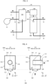
- Fig. 3 is a view schematically illustrating a hydrolysis device 10 including a flow straightening device 100 in accordance with Embodiment 3.
- the hydrolysis device 10 in accordance with Embodiment 3 is a device that supplies a gas containing ammonia to a NOx removal catalyst.
- the hydrolysis device 10 includes, in addition to a flow straightening device 100, a burner unit 300 and a hydrolysis reaction vessel 400.
- the burner unit 300 is a device that supplies, to the hydrolysis reaction vessel 400, a high-temperature gas that is required to cause a hydrolysis reaction of urea water.
- the flow straightening device 100 is connected to the burner unit 300 and the hydrolysis reaction vessel 400 at a location between the burner unit 300 and the hydrolysis reaction vessel 400. Preferably, the flow straightening device 100 is positioned at a location very close to the hydrolysis reaction vessel 400.
- the burner unit 300 includes a combustion chamber 301 and a burner 302.
- the burner 302 is connected to a fuel line 14.
- a fuel to be supplied to the burner 302 via the fuel line 14 can be any of Bunker A heavy oil, Bunker B heavy oil, Bunker C heavy oil, light oil, a gas fuel made of a hydrocarbon gas, and other fuels.
- the combustion chamber 301 has a tubular shape elongated in its axial direction, more preferably a cylindrical shape, and has a bottom provided with the burner 302.
- an extraction gas from the exhaust gas from an engine such as a diesel engine is introduced into the combustion chamber 301 via a gas extraction line 11, and a combustion gas discharged from the burner unit 300 and the extraction gas from the exhaust gas from the engine are mixed in the combustion chamber 301. Then, a resultant mixture gas passes through the flow straightening device 100, and consequently the gas stream is straightened and the degree of unevenness is temperature is improved.
- the burner unit 300 refers to the flow rate and temperature of the gas to be supplied to the hydrolysis reaction vessel 400 to regulate the combustion appropriately.
- the hydrolysis reaction vessel 400 is a device that hydrolyzes urea water in its inside to generate ammonia.
- the hydrolysis reaction vessel 400 is provided with a nozzle 401.
- the nozzle 401 is supplied with the urea water via a supply line 15.
- the nozzle 401 sprays the urea water to a high-temperature gas introduced into the hydrolysis reaction vessel 400. Then, the urea water thus sprayed is hydrolyzed at a high temperature, and consequently ammonia is generated.
- the hydrolysis reaction vessel 400 has a tubular shape elongated in its axial direction or a polygonal tubular shape whose radial cross-section shape is a square.
- the shape of the hydrolysis reaction vessel 400 is not limited to the polygonal tube.
- the hydrolysis reaction vessel 400 may have a cylindrical shape.
- the hydrolysis reaction vessel 400 may include, in its inside, a hydrolysis catalyst that further facilitates the hydrolysis reaction.
- the hydrolysis reaction vessel 400 supplies, through a processed gas line 16, a high-temperature processed gas mixed with ammonia.
- Fig. 4 is a view schematically illustrating a structure of the flow straightening device 100 in accordance with Embodiment 3.
- Fig. 4 includes an A-A cross-section view 1041 of the flow straightening device 100 viewed in a front side and a B-B cross-section view 1042 of the flow straightening device 100 viewed in a left side. The positions in which the cross sections are taken are indicated in the cross-section views in Fig. 4 .
- the flow straightening device 100 includes a housing 110 and a tube part 120.
- the housing 110 has a rectangular parallelepiped shape.
- the housing 110 is hollow in its inside, and has an internal space 117 surrounded by the housing 110.
- the housing 110 which has the rectangular parallelepiped shape, has one side surface (a side surface on the front side) constituting a first side surface 111, which is a side surface close to an outlet.
- One side surface intersecting the first side surface 111 at right angles constitutes a second side surface 112, which is a side surface close to an inlet of a gas stream.
- a side surface opposed to the first side surface 111 is a third side surface 113.
- a side surface opposed to the second side surface 112 is a fourth side surface 114.
- the other two side surfaces are a fifth side surface 115 (left side surface) and a sixth side surface 116 (right side surface).
- the fifth side surface 115 is opposed to the sixth side surface 116.
- x-y-z coordinate systems for the housing 110 having the rectangular parallelepiped shape are defined as follows. Assuming that the first side surface 111 and the third side surface 113 are orthogonal to an x-axis, a direction extending from the inside of the housing 110 toward the outside of the housing 110 over the first side surface 111 is referred to as an x-axis positive direction. Assuming that the second side surface 112 and the fourth side surface 114 are planes orthogonal to a y-axis, a direction extending from the outside of the housing 110 toward the inside of the housing 110 over the second side surface 112 is referred to as a y-axis positive direction.
- the fifth side surface 115 and the sixth side surface 116 are planes orthogonal to a z-axis
- the fifth side surface 115 is positioned advanced in a z-axis positive direction more than the sixth side surface 116.
- the x-y-z coordinate systems are indicated.
- the second side surface 112 has a portion that is at or close to a center of the second side surface 112 and that is provided with an inlet opening part 102.
- the inlet opening part 102 has a circular shape. This is because that piping (duct) connected to the flow straightening device 100 typically has a circular cross-sectional shape.
- the inlet opening part 102 constitutes an introduction port through which a gas is introduced into the flow straightening device 100. With this, while the flow straightening device 100 is in use, the gas stream is introduced into the flow straightening device 100 through the inlet opening part 102 from the outside of the flow straightening device 100 so that the gas stream flows in a y-direction.
- a second direction which is a direction of the gas stream introduced from the inlet opening part 102, is the y-direction.
- the first side surface 111, the fifth side surface 115, the third side surface 113, and the sixth side surface 116 of the housing 110 constitute an outer tube. That is, these side surfaces are side walls of the outer tube. An axial direction of the outer tube is in parallel with the y-direction.
- the second side surface 112, in which the inlet opening part 102 is provided, is at one end of the outer tube.
- the second side surface 112, in which the inlet opening part 102 is provided constitutes a flow passage enlarging part.
- the fourth side surface 114 which is opposed to the second side surface 112, is at the other end of the outer tube, and constitutes a control wall that reverses the gas stream flowing into the outer tube through the one end toward the other end.
- the fourth side surface 114 which is the control wall, is a wall surface without an opening, and closes the other end of the outer tube.
- the first side surface 111 has a portion that is at or close to a center of the first side surface 111 and that is provided with an outlet opening part 101.
- the tube part 120 penetrates through the first side surface 111 at the outlet opening part 101.
- the tube part 120 is opened in its both ends, and has a straight tubular shape extending in its axial direction.
- the outlet opening part 110 has a circular shape
- the tube part 120 has a cylindrical shape.
- the tube part 120 has an inner diameter and an outer diameter that are substantially constant in the axial direction of the tube part 120.
- a second end 121 of the tube part 120 which penetrates through the first side surface 111, is one end in its axial direction, and is positioned outside the housing 110.
- a first end 122 of the tube part 120 is the other end in its axial direction, and is positioned in the internal space 117 of the housing 110. That is, the tube part 120 is set to the housing 110 so as to extend in a first direction from the first end 122 toward the first side surface 111.
- the axial direction (first direction) of the tube part 120 is orthogonal to the first side surface 111 (i.e., in parallel with the x-axis).
- the second end 121 and the first end 122 of the tube part 120 are on a plane being in parallel with the first side surface 111 (i.e., a plane being in parallel with a y-z plane).
- the second end 121 of the tube part 120 constitutes an outlet through which the gas stream is discharged to the outside of the flow straightening device 100.
- the gas stream flows in an x-direction from the inside of the flow straightening device 100 toward the outside of the flow straightening device 100. That is, the tube part 120 constitutes a flow passage of the gas stream flowing in the first direction from the internal space 117 of the housing 110 so as to be discharged to the outside.
- the second end 121 of the tube part 120 is an outlet part of the tube part 120, and the first end 122 is an inlet part. In this case, the gas stream is discharged to the outside through the outlet opening part 101 provided in the first side surface 111.
- the tube part 120 which constitutes the outlet-side flow passage of the gas stream, penetrates through the first side surface 111 so as to protrude into the internal space 117.
- An outer surface of the tube part 120 is positioned so as to block the gas stream being introduced from the inlet opening part 102 in the second direction.
- the tube part 120 is partially disposed in a space virtually extended from the inlet opening part 102 in the second direction (y-direction) (i.e., in a trajectory along which the inlet opening part 102 is virtually moved in the second direction).
- the inlet opening part 102 which constitutes the introduction port, is set in the housing 110 such that a center axis of the inlet opening part 102 intersects the tube part 120.
- the gas stream introduced from the inlet opening part 102 in the second direction includes a center part, and collides with the outer surface of the tube part 120.
- each of the inlet opening part 102, which constitutes the introduction port, and the second end 121 of the tube part 120, which constitutes the outlet of the gas stream, may be provided with a flange for connection and fixing to the piping, as appropriate.
- Each of the housing 110 and the tube part 120 of the flow straightening device 100 may be made of a stainless steel, but may alternatively be made of another material, particularly another metal.
- the size of the housing 110 of the flow straightening device 100 may be defined as follows.
- Each of the first side surface and the second side surface is constituted by sides each being within a range of 0.5 m to 2 m.
- a ratio of an area of the inlet opening part 102 with respect to an area of the second side surface 112 is preferably approximately 1% to approximately 50%.
- a ratio of a cross-section area of a portion of the tube part 120 which portion is at or close to the first end 122 with respect to an area of the first side surface is preferably approximately 1% to approximately 50%.
- the sizes of the parts of the flow straightening device 100 may be designed as appropriate depending on the flow rate of a gas stream to be applied.
- the flow straightening device 100 functions as follows.
- a combustion gas from the burner unit 300 and an extraction gas from an exhaust gas from the engine are mixed in the combustion chamber 301, so as to yield a gas stream (a gas stream of an extraction gas heated by the burner unit 300).
- the gas stream passes through the flow straightening device 100 so as to be supplied to the hydrolysis reaction vessel 400.
- the gas stream being introduced into the flow straightening device 100 through the inlet opening part 102 and flowing mainly in the second direction, i.e., the y-direction, collides with the outer surface of the tube part 120 extending in the x-axis direction, which is the first direction, and makes a detour to flow toward a part behind the tube part 120.
- the fourth side surface 114 which is a portion of the housing 110 opposed to the inlet opening part 10, the gas stream cannot advance farther in the y-direction, and consequently the direction of the gas stream is changed. That is, the fourth side surface 114 changes the direction of the gas stream introduced from the inlet opening part 102 in the second direction, and accordingly reverses at least a portion of the gas stream.
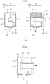
- Variation 2 is a variation of Embodiment 3, and is similar to Embodiment 3 except for a shape of a tube part of a flow straightening device.
- Fig. 6 is a view schematically illustrating a structure of a flow straightening device 210 in accordance with Variation 2, and corresponds to the B-B cross-section view 1042 shown in Fig. 4 .
- the closing plate 221 can be fixed to the housing 110 by fixing a bolt and a nut to a flange provided in the housing 110.
- the closing plate 221 may be fixed to the housing 110 by other method(s).
- the fixing may be carried out via a bolt and a screw hole provided in the third side surface 113 or via a fixing lever provided in the third side surface 113.
- a first end 122 of a tube part 132 of the flow straightening device 230 is positioned in an internal space 177.
- the flow straightening device 230 is the same as the flow straightening device 100 in accordance with Embodiment 3.
- the tube part 231 extends from the first end 122 toward the first side surface (outlet opening part 101), but does not reach the first side surface 111 (outlet opening part 101).
- a second end 121 of the tube part 231 is positioned inside a housing of the flow straightening device 230.
- the flow straightening device 230 includes, in its inside, the function of the piping part for use in connection between the flow straightening device and the hydrolysis reaction vessel. Therefore, the hydrolysis device to which the flow straightening device 230 is applied can be made more compact.
- Configuration Example 3 will discuss an example of a piping part that can be connected to an inlet opening part 102 of a flow straightening device in a hydrolysis device.
- a z-direction i.e., a direction orthogonal to an axial direction of the tube part 120
- the degree of unevenness may possibly not be improved adequately.
- a swirl device 600 such as the one shown in Fig. 10 may be connected to the inlet opening part 102 of the flow straightening device as needed. With this, the unevenness can be changed into unevenness in a desired direction.
- the swirl device 600 is a piping part that causes the gas stream passing therethrough to swirl around a center axis as the gas stream advances along the swirl device 600.
- the swirl device 600 includes a cylindrical part 601 and a twisted plate 602 disposed inside the cylindrical part 601.
- the twisted plate 602 is a member that divides an internal space of the cylindrical part 601 into two and that is twisted about the center axis along an axial direction of the cylindrical part 601.
- a cross section of the twisted plate 602 seems to rotate gradually.
- the twisted plate 602 is twisted so that an angle of 90° is made by a gas-stream inlet side and a gas-stream outlet side of the twisted plate 602.
- the angle at which the twisted plate 602 is twisted may be set as appropriate in accordance with the direction of the unevenness in the inlet opening part 102 of the flow straightening device 100.
- Fig. 11 is a view schematically illustrating a hydrolysis device 20 including a flow straightening device 240 in accordance with Embodiment 4.
- the hydrolysis device 20 in accordance with Embodiment 4 includes two hydrolysis reaction vessels 400.
- the hydrolysis device 20 in accordance with Embodiment 4 differs from the hydrolysis device 10 in accordance with Embodiment 3.
- the flow straightening device 240 in accordance with Embodiment 4 has two outlets of a gas stream. Processed gases from the respective hydrolysis reaction vessels 400 are merged into one, and the merged gas is supplied to the outside through a processed gas line 16.
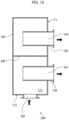
- Fig. 12 is a view schematically illustrating a structure of a flow straightening device 240, and corresponds to the B-B cross-section view 1042 shown in Fig. 4 .
- a first side surface 111 of a housing 241 has two outlet opening parts 101 arranged side by side in a y-direction (i.e., a direction perpendicular to a second side surface 112).
- Tube parts 120 respectively penetrate through the outlet opening parts 101 so as to constitute two outlets (second ends 121 of the tube parts 120).
- An internal space 117 of the housing 241 has a distribution plate 242 that extends in parallel with a second side surface 112 (i.e., in parallel with a z-x plane) and that divides the internal space 117 into two.
- the distribution plate 242 is made of a so-called punching board having multiple holes. The distribution plate 242 adjusts a flow rate ratio between the gas streams from the two outlets.
- the distribution plate 242 functions as a control wall that reverses at least a portion of the gas stream introduced from the inlet opening part 102 in a second direction. This function corresponds to the effects given by the fourth side surface 114 of the flow straightening device 100 in accordance with Embodiment 3. Meanwhile, for a gas stream that is to be discharged through the other of the tube parts 120 farther from the inlet opening part 102, the distribution plate 242 carries out a function corresponding to the inlet opening part 102 of the flow straightening device 100 in accordance with Embodiment 3.
- Embodiment 4 also brings about similar effects given by Embodiment 3. According to the configuration in accordance with Embodiment 4, which employs a plurality of hydrolysis reaction vessels 400, it is possible to easily scale up the capacity of the hydrolysis device.
- Variation 4 is a variation of Embodiment 4, and is similar to Embodiment 4 except for a configuration of a flow straightening device.
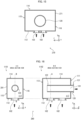
- Fig. 13 is a view schematically illustrating a structure of a flow straightening device 250 in accordance with Variation 4.
- Fig. 13 includes an A-A cross-section view 1131 of the flow straightening device 250 viewed in a front side (in an x-axis negative direction) and a B-B cross-section view 1132 of the flow straightening device 250 viewed in a left side (in a z-axis negative direction).
- a first side surface 111 of a housing 251 has two outlet opening parts 101 arranged side by side in a z-direction (in parallel with a second side surface 112).
- Tube parts 120 respectively penetrate through the outlet opening parts 101 so as to constitute two outlets (second ends 121 of the tube parts 120).
- the tube parts 120 respectively have center axes positioned on a plane orthogonal to a direction (y-axis direction) extending from one end of an outer tube (the first side surface 111, a fifth side surface 115, a third side surface 113, and a sixth side surface 116) to the other end of the outer tube.
- the flow straightening device 250 is configured such that a gas stream introduced into an internal space 117 of the housing 251 in a second direction (y-direction) through an inlet opening part 102, which is provided in a portion of the second side surface 112, is blocked by the tube parts 120.
- the tube parts 120 are partially disposed in a space virtually extended from the inlet opening part 102 in the second direction (y-direction) (i.e., in a trajectory along which the inlet opening part 102 is virtually moved in the second direction).
- a center axis of the inlet opening part 102 does not intersect the tube parts 120.
- Variation 5 is an example in which a flow straightening device has two introduction ports of gas streams.
- Fig. 14 is a view schematically illustrating a structure of a flow straightening device 260 in accordance with Variation 5.
- a second side surface 112 of a housing 261 has an inlet opening part, and, in addition, a side surface (a fifth side surface in the example shown in Fig. 14 ) orthogonal to a first side surface 111 and to the second side surface 112 has a portion provided with an inlet opening part 105. Consequently, two introduction ports communicating with an internal space 117 are given.
- the inlet opening part 105 is also disposed so as to have a center axis intersecting a tube part 120. With this, a gas stream introduced into the internal space 117 through the inlet opening part 102 is blocked by an outer peripheral surface of the tube part 120, and a gas stream introduced into the internal space 117 through the inlet opening part 105 is also blocked by the outer peripheral surface of the tube part 120.
- the flow straightening device 260 can be understood as having an outer tube constituted by the first side surface 111, the fifth side surface 115, the third side surface 113, and the sixth side surface 116 of the housing 261.
- the second side surface 112, which has the inlet opening part 102 is at one end of the outer tube.
- the second side surface 112, which has the inlet opening part 102 constitutes a flow passage enlarging part.
- the fourth side surface 114 which is opposed to the second side surface 112, is at the other end of the outer tube, and constitutes a control wall that reverses the gas stream introduced into the outer tube through the one end toward the other end.
- the flow straightening device 260 can be understood as follows. That is, the outer tube is constituted by the first side surface 111, the second side surface 112, the third side surface 113, and the fourth side surface 114 of the housing 261.
- the fifth side surface 115 which has the inlet opening part 105, is at the one end of the outer tube.
- the fifth side surface 115, which has the inlet opening part 105 constitutes a flow passage enlarging part.
- the sixth side surface 116 which is opposed to the fifth side surface 115, is at the other end of the outer tube, and constitutes the control wall that reverses the gas stream introduced into the outer tube through the one end toward the other end.
- the sixth side surface 116 which is the control wall, is a wall surface without any opening, and closes the other end of the outer tube.
- Variation 6 is another example in which a flow straightening device has two introduction ports of gas streams.
- Fig. 15 is a view schematically illustrating a structure of a flow straightening device 270 in accordance with Variation 6.
- a second side surface 112 of a housing 271 has two inlet opening parts 102. Consequently, two introduction ports communicating with an internal space 117 are given.
- the two inlet opening parts 102 are arranged along a z-axis direction.
- the inlet opening parts 102 Center axes of the inlet opening parts 102 intersect a tube part 120. With this, gas streams introduced into the internal space 117 through the inlet opening parts 102 are blocked by an outer peripheral surface of the tube part 120.
- the fourth side surface 114 constitutes a control wall that reverses both the gas streams introduced into the internal space 117 through the inlet opening parts 102. Note that the two inlet opening parts 102 may alternatively be arranged side by side along an x-axis direction.
- a second side surface 112 of a housing 281 has two inlet opening parts 102. Consequently, two introduction ports communicating with an internal space 117 are given.
- the two inlet opening parts 102 are arranged along an axial direction of a tube part 120, i.e., an x-axis direction.
- the fourth side surface 114 constitutes a control wall that reverses both the gas streams introduced into the internal space 117 through the inlet opening parts 102.
- one of the inlet opening parts may be supplied with a gas stream from a burner unit 300, and the other of the inlet opening parts may be connected to a gas extraction line 11.
- the gas extraction line 11 may not be connected to the burner unit 300. That is, the extraction gas and the combustion gas may be mixed in the flow straightening device 260,270,280.
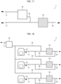
- Fig. 17 is a view schematically illustrating a configuration of a NOx removal system 1 in accordance with Embodiment 5.
- the NOx removal system 1 includes the hydrolysis device 10 and a NOx removal catalyst 19.
- the NOx removal system 1 includes a gas extraction line 11, a processed gas line 16, an exhaust gas line 17, and an exhaust line 18.
- Fig. 17 shows only the gas extraction line 11 and the processed gas line 16 out of the lines connected to the hydrolysis device 10. This applies also to the later-described embodiments.
- the hydrolysis device 10 receives an extraction gas introduced thereto through the gas extraction line 11.
- a processed gas which is a high-temperature gas containing ammonia, is supplied to the NOx removal catalyst 19 through the processed gas line 16.
- the NOx removal catalyst 19 receives an exhaust gas introduced thereto from an engine such as a diesel engine through the exhaust gas line 17.
- the processed gas line 16 is merged into the exhaust gas line at a location upstream of a portion where introduction into the NOx removal catalyst 19 takes place.
- the processed gas from the hydrolysis device 10 is mixed in the exhaust gas before being introduced into the NOx removal catalyst 19.
- the processed gas containing ammonia is mixed in the exhaust gas, and a resultant gas passes through the NOx removal catalyst 19. Consequently, a NOx removal treatment is carried out on the exhaust gas.
- the exhaust gas thus purified is discharged from the NOx removal catalyst 19 through the exhaust line 18.
- Embodiment 6 will discuss an example of a basic configuration of a NOx removal system to which the hydrolysis device 10 in accordance with Embodiment 3 is applied.
- the NOx removal system processes exhaust gases from a plurality of engines.
- Fig. 18 is a view schematically illustrating a configuration of a NOx removal system 2 in accordance with Embodiment 6.
- Fig. 18 shows three engines 21 as an example of the plurality of engines.
- the NOx removal system 2 includes one hydrolysis device 10 and three NOx removal catalysts 19 respectively provided for the engines 21.
- the NOx removal system 2 includes a gas extraction line 11 and a processed gas line 16.
- the NOx removal system 2 further includes three sets of exhaust gas lines 17, exhaust lines 18, and bypass lines 22, respectively provided for the engines 21.
- the hydrolysis device 10 receives an extraction gas introduced thereto through the gas extraction line 11.
- a processed gas is supplied to the NOx removal catalysts 19 through the processed gas line 16.
- the NOx removal catalysts 19 respectively receive exhaust gases introduced thereto from their corresponding engines 21 through the exhaust gas lines 17.
- the processed gas line 16 is branched into a plurality of lines, which are respectively merged into the exhaust gas lines 17. With this, the processed gas from the hydrolysis device 10 is mixed in the exhaust gases before being introduced into the NOx removal catalysts 19.
- the processed gas containing ammonia is mixed in the exhaust gases, and resultant gases pass through the NOx removal catalysts 19. Consequently, a NOx removal treatment is carried out on the exhaust gases.
- the exhaust gases thus purified are discharged from the NOx removal catalysts 19 through the exhaust lines 18, respectively.
- a corresponding one of the bypass lines 22 is branched off at a location upstream of a part in which a corresponding one of the processed gas lines 16 is merged into the each of the exhaust gas lines 17.
- Each of the bypass lines 22 has an end connected to a corresponding one of the exhaust lines 18.
- the bypass lines 22 are piping (bypass mechanism) for causing the exhaust gases from the engines 21 to directly flow into the exhaust lines 18, not through the NOx removal catalysts 19.
- Valves are respectively provided to (i) a part where each of the bypass lines 22 is branched off from a corresponding one of the exhaust gas lines 17 and (ii) a part where the each of the bypass lines 22 is merged into a corresponding one of the exhaust lines 18.
- opening and closing of the valves are regulated so as to appropriately control (i) a ratio between a portion of the exhaust gas from the each of the engines 21 which portion is caused to pass through a corresponding one of the NOx removal catalysts 19 (NOx removal mechanism side) and a portion of the exhaust gas from the each of the engines 21 which portion is caused to pass through a corresponding one of the bypass lines 22 (bypass mechanism side) and/or (ii) closing of each line.
- a NOx removal system 2 that can deal with exhaust gases from a plurality of engines.
- An extraction gas to be supplied to the hydrolysis device 10 through the gas extraction line 11 may be taken at a position in each exhaust gas line 17 or each exhaust line 18.
- the position where the extraction gas is taken can be selected as appropriate on the basis of known techniques. This also applies to the other embodiments and the other configuration examples.
- Embodiment 7 will discuss another example of a configuration of a NOx removal system to which the hydrolysis device 10 in accordance with Embodiment 3 is applied.
- the NOx removal system processes exhaust gases from a plurality of engines.
- Fig. 19 is a view schematically illustrating a configuration of a NOx removal system 3 in accordance with Embodiment 7.
- Fig. 19 shows three engines 21 as an example of the plurality of engines.
- the NOx removal system 3 includes one hydrolysis device 10 and one NOx removal catalyst 19 provided for the three engines 21.
- the NOx removal system 3 also includes a gas extraction line 11 and a processed gas line 16.
- the NOx removal system 3 further includes an exhaust line 18, a bypass line 22, and three exhaust gas lines 17 respectively provided for the engines 21.
- the three exhaust gas lines 17 are merged into one, and the merged line is connected to the NOx removal catalyst 19.
- the hydrolysis device 10 receives an extraction gas introduced thereto through the gas extraction line 11.
- a processed gas is supplied to the NOx removal catalyst 19 through the processed gas line 16.
- the processed gas line 16 is further merged into the merged line into which the three exhaust gas lines 17 are merged.
- the processed gas from the hydrolysis device 10 is mixed in the exhaust gas before being introduced into the NOx removal catalyst 19.
- the processed gas containing ammonia is mixed in the exhaust gas, and a resultant gas passes through the NOx removal catalyst 19. Consequently, a NOx removal treatment is carried out on the exhaust gas.
- the exhaust gas thus purified is discharged from the NOx removal catalyst 19 through the exhaust line 18.
- bypass line 22 is branched off at a location upstream of a part in which the processed gas line 16 is merged into the exhaust gas line 17.
- the bypass line 22 has an end connected to the exhaust line 18.
- the bypass line 22 is piping (bypass mechanism) for causing the exhaust gases from the engines 21 to directly flow into the exhaust line 18, not through the NOx removal catalyst 19.
- Valves are respectively provided to (i) a part where the bypass line 22 is branched off from the exhaust gas line 17 and (ii) a part where the bypass line 22 is merged into the exhaust line 18.
- opening and closing of the valves are regulated so as to appropriately control (i) a ratio between a portion of an exhaust gas from the each of the engines 21 that is caused to pass through the NOx removal catalyst 19 (NOx removal mechanism side) and a portion of the exhaust gas from the each of the engines 21 that is caused to pass through the bypass line 22 (bypass mechanism side) and/or (ii) closing of each line.
- a flow straightening device in accordance with a first aspect of the present invention is a flow straightening device through which a gas stream passes before being introduced into a hydrolysis reaction vessel that causes a hydrolysis reaction of urea water
- the flow straightening device including: an outer tube into which the gas stream flows through one end of the outer tube toward the other end of the outer tube; a control wall positioned inside the outer tube or at the other end of the outer tube, the control wall reversing at least a portion of the gas stream flowing into the outer tube through the one end toward the other end; and at least one tube part which is at least partially positioned at a location that is inside the outer tube and that is between the one end and the control wall, the at least one tube part constituting a flow passage of the gas stream flowing from an inside of the outer tube toward an outside of the outer tube through a side wall of the outer tube so as to introduce the gas stream inside the outer tube into the hydrolysis reaction vessel, the at least one tube part having an in
- a flow straightening device in accordance with a second aspect of the present invention may be configured such that, in the first aspect, the inlet part of the at least one tube part is positioned at a location that is inside the outer tube and that is between the one end and the control wall, the outlet part is positioned outside the outer tube, and the at least one tube part has an outer peripheral surface positioned to block at least a portion of the gas stream flowing into the outer tube through the one end toward the other end.
- a flow straightening device in accordance with a third aspect of the present invention may be configured to such that, in the first or second aspect, the flow straightening device further includes a separation plate having a planar shape, the separation plate being disposed at a location that is inside the outer tube and that is between the at least one tube part and the control wall, the separation plate extending in a longitudinal direction of the at least one tube part and in a direction extending from the one end toward the other end.
- a flow straightening device in accordance with a fourth aspect of the present invention may be configured such that, in any of the first to third aspects, the at least one tube part has a tube part enlarging part in which a radial cross-section area of the at least one tube part is enlarged with increasing proximity to the outlet part from the inlet part.
- a flow straightening device in accordance with a fifth aspect of the present invention may be configured such that, in any of the first to fourth aspects, the one end of the outer tube has a flow passage enlarging part in which a cross-section area of a flow passage of the gas stream flowing into the outer tube through the one end toward the other end is enlarged.
- a flow straightening device in accordance with a sixth aspect of the present invention may be configured such that, in the fifth aspect, the flow passage enlarging part has a minimum portion in which a cross-section area of the flow passage is smaller than that of any other portion of the flow passage enlarging part, said at least one tube part has a minimum portion having a radial cross-section area smaller than that of any other portion of said at least one tube part, and the cross-section area of the minimum portion of the flow passage enlarging part is equal to or greater than the radial cross-section area of the minimum portion of said at least one tube part.
- a flow straightening device in accordance with a seventh aspect of the present invention may be configured such that, in any of the first to sixth aspects, the outer tube has a side wall which is opposed to the inlet part of the at least one tube part and which is provided with a maintenance opening part and a closing plate that is detachable and that is configured to close the maintenance opening part.
- a flow straightening device in accordance with an eighth aspect of the present invention may be configured such that, in any of the first to seventh aspects, the control wall closes the other end of the outer tube.
- a flow straightening device in accordance with a ninth aspect of the present invention may be configured such that, in the first or eighth aspect, the at least one tube part includes a plurality of tube parts, and the plurality of tube parts respectively have center axes positioned on a plane substantially orthogonal to a direction extending from the one end of the outer tube toward the other end of the outer tube.
- a hydrolysis device in accordance with a tenth aspect of the present invention includes: a flow straightening device described in any of the first to ninth aspects; a hydrolysis reaction vessel that causes a hydrolysis reaction of urea water; and a burner unit configured to burn a fuel so as to supply a heated gas to the flow straightening device.
- a hydrolysis device in accordance with an eleventh aspect of the present invention includes: a flow straightening device described in the ninth aspect; a plurality of hydrolysis reaction vessels each of which is configured to cause a hydrolysis reaction of urea water and to receive a gas stream flowing out of a corresponding one of the plurality of tube parts; and a burner unit configured to burn a fuel so as to supply a heated gas to the flow straightening device.
- a hydrolysis device in accordance with a twelfth aspect of the present invention may be configured such that, in the tenth or eleventh aspect, the hydrolysis device further includes a swirl device configured to cause a gas stream coming from the burner unit to swirl around a center axis of the outer tube and then to introduce the gas stream into the flow straightening device through the one end of the outer tube.
- a swirl device configured to cause a gas stream coming from the burner unit to swirl around a center axis of the outer tube and then to introduce the gas stream into the flow straightening device through the one end of the outer tube.
- a hydrolysis device in accordance with a thirteenth aspect of the present invention may be configured such that, in any of the tenth to twelfth aspects, the hydrolysis reaction vessel comprises one or more hydrolysis reaction vessels each of which has a tubular shape elongated in an axial direction of the hydrolysis reaction vessel, the burner unit includes a combustion chamber that burns the fuel, the combustion chamber having a tubular shape elongated in an axial direction of the combustion chamber, and the one or more hydrolysis reaction vessels and the burner unit are arranged so that axial directions of the one or more hydrolysis reaction vessels are in parallel with the axial direction of the combustion chamber.
- a NOx removal system in accordance with a fourteenth aspect of the present invention is a NOx removal system that carries out a NOx removal treatment on an exhaust gas from an engine, including: a hydrolysis device described in any of the tenth to thirteenth aspects; and a NOx removal mechanism configured to mix the exhaust gas with a processed gas from the hydrolysis reaction vessel to yield a mixture gas, to introduce the mixture gas into a NOx removal catalyst, and then to discharge a resultant.
- a NOx removal system in accordance with a fifteenth aspect of the present invention is a NOx removal system that carries out a NOx removal treatment on exhaust gases from a plurality of engines, including: a hydrolysis device described in any of the tenth to thirteenth aspects; and NOx removal mechanisms and bypass mechanisms respectively provided for the plurality of engines, wherein the NOx removal mechanisms are configured to respectively mix the exhaust gases from the plurality of engines with a processed gas from the hydrolysis reaction vessel to yield mixture gases, to introduce the mixture gases into NOx removal catalysts, and then to discharge resultants; and the bypass mechanisms are configured to respectively cause the exhaust gases from the plurality of engines to bypass the NOx removal mechanisms so as to discharge the exhaust gases.
- a NOx removal system in accordance with a sixteenth aspect of the present invention is a NOx removal system that carries out a NOx removal treatment on exhaust gases from a plurality of engines, including: a hydrolysis device described in any of the tenth to thirteenth aspects; and a NOx removal mechanism configured to mix the exhaust gases from the plurality of engines with a processed gas from the hydrolysis reaction vessel to yield a mixture gas, to introduce the mixture gas into a NOx removal catalyst, and then to discharge a resultant; and a bypass mechanism configured to cause the exhaust gases from the plurality of engines to bypass the NOx removal mechanism so as to discharge the exhaust gases.
- a flow straightening device in accordance with a seventeenth aspect of the present invention is a flow straightening device through which a gas stream passes before being introduced into a hydrolysis reaction vessel that causes a hydrolysis reaction of urea water
- the flow straightening device including: a housing; at least one tube part; and a control wall, wherein the at least one tube part has a first end positioned in an internal space of the housing, the at least one tube part is disposed to extend in a first direction from the first end, the at least one tube part constitutes a flow passage of the gas stream flowing from the internal space of the housing toward an outside of the housing through an outlet opening part, which is provided in a portion of the housing so as to face the first direction from the first end, the housing has, in a portion thereof, an inlet opening part through which the gas stream is introduced from the outside in a second direction toward the internal space of the housing, the control wall is disposed at a location that is opposed to the inlet opening part and faces the internal space or at a position inside the internal
- a flow straightening device in accordance with an eighteenth aspect of the present invention is a flow straightening device through which a gas stream passes before being introduced into a hydrolysis reaction vessel that causes a hydrolysis reaction of urea water
- the flow straightening device including: a housing; and at least one tube part, wherein the at least one tube part has a first end positioned in an internal space of the housing, the at least one tube part is disposed to extend in a first direction from the first end, the at least one tube part constitutes a flow passage of the gas stream flowing from the internal space of the housing toward an outside of the housing through an outlet opening part, which is provided in a portion of the housing so as to face the first direction from the first end, the housing has, in a portion thereof, an inlet opening part through which the gas stream is introduced from the outside in a second direction toward the internal space of the housing, and the first direction and the second direction are different directions.
- a flow straightening device in accordance with a nineteenth aspect of the present invention may be configured such that, in the eighteenth aspect, at least a portion of the gas stream introduced from the inlet opening part in the second direction is reversed by a portion of the housing which portion is opposed to the inlet opening part.
- a flow straightening device in accordance with a twentieth aspect of the present invention may be configured such that, in any of the seventeenth to nineteenth aspects, an outer surface of the at least one tube part is positioned so as to block the gas stream being introduced from the inlet opening part in the second direction.
- a flow straightening device in accordance with a twenty-first aspect of the present invention may be configured such that, in any of the seventeenth to twentieth aspects, the at least one tube part is at least partially positioned in a space virtually extended from the inlet opening part in the second direction.
- a flow straightening device in accordance with a twenty-second aspect of the present invention may be configured such that, in any of the seventeenth to twenty-first aspects, a center axis of the inlet opening part intersects the at least one tube part.
- a flow straightening device in accordance with a twenty-third aspect of the present invention may be configured such that, in any of the seventeenth to twenty-second aspects, the gas stream introduced from the inlet opening part in the second direction has a cross-section area that is enlarged when the gas stream is introduced from the inlet opening part into the internal space of the housing.
- a flow straightening device in accordance with a twenty-fourth aspect of the present invention may be configured such that, in any of the seventeenth to twenty-third aspects, the first direction and the second direction are substantially perpendicular to each other.
- a flow straightening device in accordance with a twenty-fifth aspect of the present invention may be configured such that, in any of the seventeenth to twenty-fourth aspects, the flow straightening device further includes a separation plate having a planar shape, the separation plate being disposed at a location that is in the internal space of the housing and that is opposite to the inlet opening part across the at least one tube part, the separation plate being substantially in parallel with the first direction and the second direction.
- a flow straightening device in accordance with a twenty-sixth aspect of the present invention may be configured such that, in any of the seventeenth to twenty-fifth aspects, the at least one tube part has a portion which is close to the first end and which has a diameter enlarged with increasing proximity to the first end.
- a flow straightening device in accordance with a twenty-seventh aspect of the present invention may be configured such that, in any of the seventeenth to twenty-sixth aspects, the housing has a portion which is opposed to the outlet opening part and which is provided with a maintenance opening part and a closing plate that is detachable and that is configured to close the maintenance opening part.
- a flow straightening device in accordance with a twenty-eighth aspect of the present invention may be configured such that, in any of the seventeenth to twenty-seventh aspects, the at least one tube part includes a plurality of tube parts.
- a hydrolysis device in accordance with a twenty-ninth aspect of the present invention includes: a flow straightening device described in any of the seventeenth to twenty-eighth aspects; a hydrolysis reaction vessel that causes a hydrolysis reaction of urea water; and a burner unit configured to burn a fuel so as to supply a heated gas to the flow straightening device.
- a hydrolysis device in accordance with a thirtieth aspect of the present invention includes: a flow straightening device described in the twenty-eighth aspect; a plurality of hydrolysis reaction vessels each of which is configured to cause a hydrolysis reaction of urea water and to receive a gas stream flowing out of a corresponding one of the plurality of tube parts; and a burner unit configured to burn a fuel so as to supply a heated gas to the flow straightening device.
- a hydrolysis device in accordance with a thirty-first aspect of the present invention may be configured such that, in the twenty-ninth or thirtieth aspect, the hydrolysis device further includes a swirl device configured to cause a gas stream coming from the burner unit to swirl around a center axis of the inlet opening part so as to be introduced into the flow straightening device through the inlet opening part.
- a hydrolysis device in accordance with a thirty-second aspect of the present invention may be configured such that, in any of the twenty-ninth to thirty-first aspects, the hydrolysis reaction vessel comprises one or more hydrolysis reaction vessels each of which has a tubular shape elongated in an axial direction of the hydrolysis reaction vessel, the burner unit includes a combustion chamber that burns the fuel, the combustion chamber having a tubular shape elongated in an axial direction of the combustion chamber, and the one or more hydrolysis reaction vessels and the burner unit are arranged so that axial directions of the one or more hydrolysis reaction vessels are in parallel with the axial direction of the combustion chamber.
- a NOx removal system in accordance with a thirty-third aspect of the present invention is a NOx removal system that carries out a NOx removal treatment on an exhaust gas from an engine, including: a hydrolysis device described in any of the twenty-ninth to thirty-second aspects; and a NOx removal mechanism configured to mix the exhaust gas with a processed gas from the hydrolysis reaction vessel to yield a mixture gas, to introduce the mixture gas into a NOx removal catalyst, and then to discharge a resultant.
- a NOx removal system in accordance with a thirty-fourth aspect of the present invention is a NOx removal system that carries out a NOx removal treatment on exhaust gases from a plurality of engines, including: a hydrolysis device described in any of the twenty-ninth to thirty-second aspects; and NOx removal mechanisms and bypass mechanisms respectively provided for the plurality of engines, wherein the NOx removal mechanisms are configured to respectively mix the exhaust gases from the plurality of engines with a processed gas from the hydrolysis reaction vessel to yield mixture gases, to introduce the mixture gases into NOx removal catalysts, and then to discharge resultants, and the bypass mechanisms are configured to respectively cause the exhaust gases from the plurality of engines to bypass the NOx removal mechanisms so as to discharge the exhaust gases.
- a NOx removal system in accordance with a thirty-fifth aspect of the present invention is a NOx removal system that carries out a NOx removal treatment on exhaust gases from a plurality of engines, including: a hydrolysis device described in any of the twenty-ninth to thirty-second aspects; and a NOx removal mechanism configured to mix the exhaust gases from the plurality of engines with a processed gas from the hydrolysis reaction vessel to yield a mixture gas, to introduce the mixture gas into a NOx removal catalyst, and then to discharge a resultant; and a bypass mechanism configured to cause the exhaust gases from the plurality of engines to bypass the NOx removal mechanism so as to discharge the exhaust gases.
Landscapes
- Engineering & Computer Science (AREA)
- Chemical & Material Sciences (AREA)
- Chemical Kinetics & Catalysis (AREA)
- Environmental & Geological Engineering (AREA)
- Health & Medical Sciences (AREA)
- Combustion & Propulsion (AREA)
- Biomedical Technology (AREA)
- Oil, Petroleum & Natural Gas (AREA)
- General Chemical & Material Sciences (AREA)
- Analytical Chemistry (AREA)
- General Engineering & Computer Science (AREA)
- Mechanical Engineering (AREA)
- Toxicology (AREA)
- Dispersion Chemistry (AREA)
- Physical Or Chemical Processes And Apparatus (AREA)
- Exhaust Gas After Treatment (AREA)
- Exhaust Gas Treatment By Means Of Catalyst (AREA)
Claims (16)
- Strömungsbegradigungsvorrichtung (100), durch die ein Gasstrom strömt, bevor er in ein Hydrolyse-Reaktionsgefäß (400) eingeleitet wird, das eine Hydrolyse-Reaktion von Harnstoffwasser bewirkt, wobei die Strömungsbegradigungsvorrichtung (100) umfasst:ein Außenrohr (110), in das der Gasstrom durch ein Ende des Außenrohrs (110) zum anderen Ende des Außenrohrs (110) strömt, das dem einen Ende gegenüberliegt;eine Steuerwand (114), die innerhalb des Außenrohrs (110) oder am anderen Ende des Außenrohrs (110) angeordnet ist, wobei die Steuerwand (114) mindestens einen Teil des Gasstroms, der in das Außenrohr (110) durch das eine Ende zum anderen Ende strömt, umkehrt; undmindestens einen Rohrteil (120), der zumindest teilweise an einer Stelle angeordnet ist, die sich im Inneren des Außenrohrs (110) und zwischen dem einen Ende und der Steuerwand (114) befindet, wobei der mindestens eine Rohrteil (120) einen Strömungsdurchgang des Gasstroms bildet, der von einer Innenseite des Außenrohrs (110) zu einer Außenseite des Außenrohrs (110) durch eine Seitenwand (111) des Außenrohrs (110) strömt, um den Gasstrom innerhalb des Außenrohrs (110) in das Hydrolyse-Reaktionsgefäß (400) einzuführen, wobei der mindestens eine Rohrteil (120) einen Einlassteil (122) und einen Auslassteil (121) für den Gasstrom aufweist.
- Strömungsbegradigungsvorrichtung (100) nach Anspruch 1, wobeider Einlassteil (122) des mindestens einen Rohrteils (120) an einer Stelle positioniert ist, die sich im Inneren des Außenrohrs (110) befindet und die zwischen dem einen Ende und der Steuerwand (114) liegt,der Auslassteil (121) außerhalb des Außenrohrs (110) angeordnet ist, undder mindestens eine Rohrteil (120) eine äußere Umfangsfläche aufweist, die so angeordnet ist, dass sie mindestens einen Teil des Gasstroms blockiert, der in das Außenrohr (110) durch das eine Ende in Richtung des anderen Endes fließt.
- Strömungsbegradigungsvorrichtung (100) nach Anspruch 1 oder 2, ferner umfassend:
eine Trennplatte (201) mit einer ebenen Form, wobei die Trennplatte (201) an einer Stelle angeordnet ist, die sich im Inneren des Außenrohrs (110) befindet und die zwischen dem mindestens einen Rohrteil (120) und der Steuerwand (114) liegt, wobei sich die Trennplatte (201) in einer Längsrichtung des mindestens einen Rohrteils (120) und in einer Richtung erstreckt, die sich von dem einen Ende zu dem anderen Ende erstreckt. - Strömungsbegradigungsvorrichtung (100) nach einem der Ansprüche 1 bis 3, wobei
der mindestens eine Rohrteil (120) einen Rohrteilvergrößerungsteil aufweist, in dem eine radiale Querschnittsfläche des mindestens einen Rohrteils (120) mit zunehmender Nähe zum Auslassteil (121) vom Einlassteil (122) vergrößert wird. - Strömungsbegradigungsvorrichtung (100) nach einem der Ansprüche 1 bis 4, wobei
das eine Ende des Außenrohrs (110) einen Strömungsdurchgangsvergrößerungsteil aufweist, in dem eine Querschnittsfläche eines Strömungsdurchgangs des Gasstroms, der in das Außenrohr (110) durch das eine Ende zum anderen Ende strömt, vergrößert wird. - Strömungsdurchgangsvergrößerungsteil nach Anspruch 5, wobei
der Strömungsdurchgangsvergrößerungsteil einen minimalen Abschnitt aufweist, in dem eine Querschnittsfläche des Strömungsdurchgangs kleiner ist als die eines beliebigen anderen Abschnitts des Strömungsdurchgangsvergrößerungsteils, der mindestens eine Rohrteil (120) einen minimalen Abschnitt aufweist, der eine radiale Querschnittsfläche aufweist, die kleiner ist als die eines beliebigen anderen Abschnitts des mindestens einen Rohrteils (120), und die Querschnittsfläche des minimalen Abschnitts des Strömungsdurchgangsvergrößerungsteil gleich oder größer ist als die radiale Querschnittsfläche des minimalen Abschnitts des mindestens einen Rohrteils (120). - Strömungsbegradigungsvorrichtung (100) nach einem der Ansprüche 1 bis 6, wobei
das Außenrohr (110) eine Seitenwand hat, die dem Einlassabschnitt (122) des mindestens einen Rohrteils (120) gegenüberliegt und die mit einem Wartungsöffnungsteil (103) und einer Verschlussplatte (221) versehen ist, die abnehmbar ist und die dazu konfiguriert ist, den Wartungsöffnungsteil (103) zu schließen. - Strömungsbegradigungsvorrichtung (100) nach einem der Ansprüche 1 bis 7, wobei
die Steuerwand (114) das andere Ende des Außenrohrs (110) verschließt. - Strömungsbegradigungsvorrichtung (100) nach einem der Ansprüche 1 bis 8, wobeider mindestens eine Rohrteil (120) eine Vielzahl von Rohrteilen (120) umfasst, unddie Vielzahl von Rohrteile (120) jeweils Mittelachsen aufweisen, die auf einer Ebene positioniert sind, die im Wesentlichen orthogonal zu einer Richtung ist, die sich von dem einen Ende des Außenrohrs (110) zu dem anderen Ende des Außenrohrs (110) erstreckt.
- Hydrolyse-Vorrichtung (10, 20), umfassend:eine in einem der Ansprüche 1 bis 9 genannte Strömungsbegradigungsvorrichtung (100);ein Hydrolyse-Reaktionsgefäß (400), das eine Hydrolyse-Reaktion von Harnstoffwasser bewirkt; undeine Brenner-Einheit (300), die dazu konfiguriert ist, einen Brennstoff zu verbrennen, um der Strömungsbegradigungsvorrichtung (100) ein erhitztes Gas zuzuführen.
- Hydrolyse-Vorrichtung (10, 20), umfassend:eine Strömungsbegradigungsvorrichtung (100) nach Anspruch 9;eine Vielzahl von Hydrolyse-Reaktionsgefäßen (400), von denen jedes dazu konfiguriert ist, eine Hydrolyse-Reaktion von Harnstoffwasser zu bewirken und einen Gasstrom aufzunehmen, der aus einem entsprechenden der Vielzahl von Rohrteilen (120) ausströmt; undeine Brenner-Einheit (300), die dazu konfiguriert ist, einen Brennstoff zu verbrennen, um der Strömungsbegradigungsvorrichtung (100) ein erhitztes Gas zuzuführen.
- Hydrolyse-Vorrichtung (10, 20) nach Anspruch 10 oder 11, ferner umfassend:
eine Verwirbelungsvorrichtung (600), die dazu konfiguriert ist, einen von der Brenner-Einheit (300) kommenden Gasstrom um eine Mittelachse des Außenrohrs (110) zu verwirbeln und dann den Gasstrom durch das eine Ende des Außenrohrs (110) in die Strömungsbegradigungsvorrichtung (100) einzuleiten. - Hydrolyse-Vorrichtung (10, 20) nach einem der Ansprüche 10 bis 12, wobeidas Hydrolyse-Reaktionsgefäß (400) ein oder mehrere Hydrolyse-Reaktionsgefäße (400) umfasst, von denen jedes eine rohrförmige Form aufweist, die in einer axialen Richtung des Hydrolyse-Reaktionsgefäßes (400) verlängert ist,die Brenner-Einheit (300) eine Brennkammer (301) aufweist, die den Brennstoff verbrennt, wobei die Brennkammer (301) eine röhrenförmige Form hat, die in einer axialen Richtung der Brennkammer (301) verlängert ist, unddas eine oder die mehreren Hydrolyse-Reaktionsgefäße (400) und die Brenner-Einheit (300) so angeordnet sind, dass die axialen Richtungen des einen oder der mehreren Hydrolyse-Reaktionsgefäße (400) parallel zu der axialen Richtung der Brennkammer (301) verlaufen.
- NOx-Entfernungssystem (1), das eine NOx-Entfernungsbehandlung an einem Abgas von einem Motor (21) durchführt, umfassend:eine Hydrolyse-Vorrichtung (10, 20) nach einem der Ansprüche 10 bis 13; undeinen NOx-Entfernungsmechanismus, der dazu konfiguriert ist, das Abgas mit einem verarbeiteten Gas aus dem Hydrolyse-Reaktionsgefäß (400) zu mischen, um ein Gasgemisch zu erhalten, das Gasgemisch in einen NOx-Entfernungskatalysator einzuleiten und dann ein Ergebnis abzuführen.
- NOx-Entfernungssystem (1), das eine NOx-Entfernungsbehandlung an Abgasen von einer Vielzahl von Motoren (21) durchführt, umfassend:eine Hydrolyse-Vorrichtung (10, 20) nach einem der Ansprüche 10 bis 13; undNOx-Entfernungsmechanismen und Bypass-Mechanismen, die jeweils für die Vielzahl von Motoren (21) vorgesehen sind, wobeidie NOx-Entfemungsmechanismen dazu konfiguriert sind, jeweils die Abgase aus der Vielzahl von Motoren (21) mit einem verarbeiteten Gas aus dem Hydrolyse-Reaktionsgefäß (400) zu mischen, um Mischgase zu erhalten, die Mischgase in NOx-Entfernungskatalysatoren einzuleiten und dann Ergebnisse abzuführen; unddie Bypass-Mechanismen dazu konfiguriert sind, jeweils zu bewirken, dass die Abgase aus der Vielzahl von Motoren (21) die NOx-Entfemungsmechanismen umgehen, um die Abgase abzuleiten.
- NOx-Entfernungssystem (1), das eine NOx-Entfernungsbehandlung an Abgasen aus einer Vielzahl von Motoren (21) durchführt, umfassend:eine Hydrolyse-Vorrichtung (10, 20) nach einem der Ansprüche 10 bis 13; undeinen NOx-Entfernungsmechanismus, der dazu konfiguriert ist, die Abgase aus der Vielzahl von Motoren (21) mit einem verarbeiteten Gas aus dem Hydrolyse-Reaktionsgefäß (400) zu mischen, um ein Gasgemisch zu erhalten, das Gasgemisch in einen NOx-Entfernungskatalysator einzuleiten und dann ein Ergebnis abzuführen; undeinen Bypass-Mechanismus, der dazu konfiguriert ist, zu bewirken, dass die Abgase aus der Vielzahl von Motoren (21) den NOx-Entfernungsmechanismus umgehen, um die Abgase abzuleiten.
Applications Claiming Priority (2)
| Application Number | Priority Date | Filing Date | Title |
|---|---|---|---|
| JP2019204852A JP7382595B2 (ja) | 2019-11-12 | 2019-11-12 | 整流装置、加水分解装置、及び脱硝設備 |
| PCT/JP2020/029388 WO2021095305A1 (ja) | 2019-11-12 | 2020-07-31 | 整流装置、加水分解装置、及び脱硝設備 |
Publications (3)
| Publication Number | Publication Date |
|---|---|
| EP4059588A1 EP4059588A1 (de) | 2022-09-21 |
| EP4059588A4 EP4059588A4 (de) | 2023-11-08 |
| EP4059588B1 true EP4059588B1 (de) | 2025-01-01 |
Family
ID=75897710
Family Applications (1)
| Application Number | Title | Priority Date | Filing Date |
|---|---|---|---|
| EP20888646.5A Active EP4059588B1 (de) | 2019-11-12 | 2020-07-31 | Strömungsgleichrichter, hydrolyseanlage und denitrifikationsanlage |
Country Status (6)
| Country | Link |
|---|---|
| EP (1) | EP4059588B1 (de) |
| JP (1) | JP7382595B2 (de) |
| KR (1) | KR20220093207A (de) |
| CN (1) | CN114729586B (de) |
| DK (1) | DK4059588T3 (de) |
| WO (1) | WO2021095305A1 (de) |
Family Cites Families (16)
| Publication number | Priority date | Publication date | Assignee | Title |
|---|---|---|---|---|
| EP1339479B1 (de) * | 2000-12-01 | 2007-03-07 | Fuel Tech, Inc. | DURCH NEBENSTROM-HARNSTOFFABBAU ERMÖGLICHTE, SELEKTIVE KATALYTISCHE NOx-REDUKTION |
| GB2416718A (en) * | 2004-07-29 | 2006-02-08 | Eminox Ltd | Gas treatment apparatus |
| JP4766915B2 (ja) * | 2005-03-17 | 2011-09-07 | 東京瓦斯株式会社 | ボイラー廃ガスの脱硝処理方法 |
| DE102005039630B4 (de) * | 2005-08-20 | 2007-08-02 | Technische Universität Kaiserslautern | Vorrichtung, Reaktor und Verfahren zur Reduzierung von Stickoxyden im Abgasstrom von Verbrennungskraftmaschinen |
| DE102008033984B4 (de) * | 2008-07-21 | 2016-03-24 | Friedrich Boysen Gmbh & Co. Kg | Abgasanlage |
| JP2010071240A (ja) * | 2008-09-19 | 2010-04-02 | Tokyo Roki Co Ltd | 内燃機関用の排ガス浄化装置、及び旋回流発生装置 |
| JP2011064069A (ja) * | 2009-09-15 | 2011-03-31 | Toyota Industries Corp | 排気ガス処理装置 |
| EP2607641A1 (de) * | 2011-12-19 | 2013-06-26 | Mtu Friedrichshafen Gmbh | Mischeinrichtung zum Einbringen eines Reduktionsmittels in einen Abgasstrom mit schaufelförmigen Mitteln |
| JP5349576B2 (ja) * | 2011-12-27 | 2013-11-20 | 株式会社小松製作所 | 還元剤水溶液ミキシング装置及び排気ガス後処理装置 |
| JP6053096B2 (ja) * | 2012-01-12 | 2016-12-27 | 日野自動車株式会社 | 排気浄化装置 |
| US9267413B2 (en) * | 2012-06-20 | 2016-02-23 | Cnh Industrial America Llc | Exhaust system for an agricultural vehicle |
| JP6560093B2 (ja) * | 2015-10-16 | 2019-08-14 | ヤンマー株式会社 | 船舶の排気ガス浄化装置 |
| KR101804024B1 (ko) * | 2015-12-23 | 2017-12-01 | 두산엔진주식회사 | 버너장치 |
| WO2017145235A1 (ja) * | 2016-02-22 | 2017-08-31 | 日野自動車 株式会社 | 排気浄化システム |
| JP2017217982A (ja) | 2016-06-06 | 2017-12-14 | 三井造船株式会社 | 船体構造 |
| JP2019127880A (ja) * | 2018-01-24 | 2019-08-01 | フタバ産業株式会社 | 撹拌装置 |
-
2019
- 2019-11-12 JP JP2019204852A patent/JP7382595B2/ja active Active
-
2020
- 2020-07-31 EP EP20888646.5A patent/EP4059588B1/de active Active
- 2020-07-31 WO PCT/JP2020/029388 patent/WO2021095305A1/ja not_active Ceased
- 2020-07-31 KR KR1020227019143A patent/KR20220093207A/ko active Pending
- 2020-07-31 CN CN202080078586.7A patent/CN114729586B/zh active Active
- 2020-07-31 DK DK20888646.5T patent/DK4059588T3/da active
Also Published As
| Publication number | Publication date |
|---|---|
| EP4059588A4 (de) | 2023-11-08 |
| WO2021095305A1 (ja) | 2021-05-20 |
| CN114729586B (zh) | 2023-11-21 |
| KR20220093207A (ko) | 2022-07-05 |
| CN114729586A (zh) | 2022-07-08 |
| DK4059588T3 (da) | 2025-02-03 |
| EP4059588A1 (de) | 2022-09-21 |
| JP2021076094A (ja) | 2021-05-20 |
| JP7382595B2 (ja) | 2023-11-17 |
Similar Documents
| Publication | Publication Date | Title |
|---|---|---|
| CN114575976B (zh) | 在后处理系统混合排气和还原剂的系统和方法 | |
| FI125770B (fi) | Menetelmä ja pakokaasun virtausohjain pakokaasun puhdistamiseksi | |
| US10024217B1 (en) | Reductant decomposition reactor chamber | |
| US20190032535A1 (en) | Exhaust System With Mixer | |
| JP4989062B2 (ja) | 流体混合装置 | |
| US10066526B2 (en) | Exhaust gas line section for supplying liquid additive | |
| RU2375121C2 (ru) | Распыление текучих сред путем взаимного соударения потоков текучих сред | |
| US6779786B2 (en) | Mixer for mixing at least two flows of gas or other newtonian liquids | |
| CN114635773B (zh) | 用于后处理系统的分解室 | |
| CN106715853B (zh) | 排气混合组件 | |
| JP2013531166A (ja) | 排ガス処理装置 | |
| JP2008049306A (ja) | ガス混合装置 | |
| WO2019143373A1 (en) | Decomposition chamber for aftertreatment systems | |
| AU2011200135B2 (en) | Stepped down gas mixing device | |
| WO2023115905A1 (zh) | Scr混合器及车辆 | |
| EP4059588B1 (de) | Strömungsgleichrichter, hydrolyseanlage und denitrifikationsanlage | |
| KR100339317B1 (ko) | 조합형공급및혼합장치및그방법 | |
| US7198763B2 (en) | Method for distribution of gas, gas distributing device and silencer-catalyst system | |
| CN107076000B (zh) | 立式超声波分解管 | |
| KR20160094850A (ko) | 유동 유닛, 배기 가스 정화 시스템 및 배기 가스 정화 시스템을 위한 방법 | |
| CN107304702B (zh) | 用于内燃机废气后处理系统的混合装置 | |
| US20200173332A1 (en) | Apparatus for introducing and distributing a flowable additive into an exhaust gas flow |
Legal Events
| Date | Code | Title | Description |
|---|---|---|---|
| STAA | Information on the status of an ep patent application or granted ep patent |
Free format text: STATUS: THE INTERNATIONAL PUBLICATION HAS BEEN MADE |
|
| PUAI | Public reference made under article 153(3) epc to a published international application that has entered the european phase |
Free format text: ORIGINAL CODE: 0009012 |
|
| STAA | Information on the status of an ep patent application or granted ep patent |
Free format text: STATUS: REQUEST FOR EXAMINATION WAS MADE |
|
| 17P | Request for examination filed |
Effective date: 20220530 |
|
| AK | Designated contracting states |
Kind code of ref document: A1 Designated state(s): AL AT BE BG CH CY CZ DE DK EE ES FI FR GB GR HR HU IE IS IT LI LT LU LV MC MK MT NL NO PL PT RO RS SE SI SK SM TR |
|
| DAV | Request for validation of the european patent (deleted) | ||
| DAX | Request for extension of the european patent (deleted) | ||
| A4 | Supplementary search report drawn up and despatched |
Effective date: 20231011 |
|
| RIC1 | Information provided on ipc code assigned before grant |
Ipc: F01N 13/08 20100101ALI20231005BHEP Ipc: F01N 3/28 20060101ALI20231005BHEP Ipc: F01N 3/20 20060101ALI20231005BHEP Ipc: F01N 3/24 20060101ALI20231005BHEP Ipc: F01N 3/08 20060101ALI20231005BHEP Ipc: B01F 25/433 20220101ALI20231005BHEP Ipc: B01D 53/94 20060101ALI20231005BHEP Ipc: B01D 53/90 20060101ALI20231005BHEP Ipc: B01D 53/86 20060101AFI20231005BHEP |
|
| GRAP | Despatch of communication of intention to grant a patent |
Free format text: ORIGINAL CODE: EPIDOSNIGR1 |
|
| STAA | Information on the status of an ep patent application or granted ep patent |
Free format text: STATUS: GRANT OF PATENT IS INTENDED |
|
| INTG | Intention to grant announced |
Effective date: 20240730 |
|
| P01 | Opt-out of the competence of the unified patent court (upc) registered |
Free format text: CASE NUMBER: APP_52216/2024 Effective date: 20240917 |
|
| GRAS | Grant fee paid |
Free format text: ORIGINAL CODE: EPIDOSNIGR3 |
|
| GRAA | (expected) grant |
Free format text: ORIGINAL CODE: 0009210 |
|
| STAA | Information on the status of an ep patent application or granted ep patent |
Free format text: STATUS: THE PATENT HAS BEEN GRANTED |
|
| RAP3 | Party data changed (applicant data changed or rights of an application transferred) |
Owner name: VALCANO CO., LTD. Owner name: KANADEVIA CORPORATION |
|
| RAP3 | Party data changed (applicant data changed or rights of an application transferred) |
Owner name: VOLCANO CO., LTD. Owner name: KANADEVIA CORPORATION |
|
| AK | Designated contracting states |
Kind code of ref document: B1 Designated state(s): AL AT BE BG CH CY CZ DE DK EE ES FI FR GB GR HR HU IE IS IT LI LT LU LV MC MK MT NL NO PL PT RO RS SE SI SK SM TR |
|
| REG | Reference to a national code |
Ref country code: GB Ref legal event code: FG4D |
|
| REG | Reference to a national code |
Ref country code: DE Ref legal event code: R096 Ref document number: 602020044300 Country of ref document: DE |
|
| REG | Reference to a national code |
Ref country code: CH Ref legal event code: EP |
|
| REG | Reference to a national code |
Ref country code: IE Ref legal event code: FG4D |
|
| REG | Reference to a national code |
Ref country code: DK Ref legal event code: T3 Effective date: 20250131 |
|
| REG | Reference to a national code |
Ref country code: LT Ref legal event code: MG9D |
|
| REG | Reference to a national code |
Ref country code: NL Ref legal event code: MP Effective date: 20250101 |
|
| REG | Reference to a national code |
Ref country code: AT Ref legal event code: MK05 Ref document number: 1755672 Country of ref document: AT Kind code of ref document: T Effective date: 20250101 |
|
| PG25 | Lapsed in a contracting state [announced via postgrant information from national office to epo] |
Ref country code: NL Free format text: LAPSE BECAUSE OF FAILURE TO SUBMIT A TRANSLATION OF THE DESCRIPTION OR TO PAY THE FEE WITHIN THE PRESCRIBED TIME-LIMIT Effective date: 20250101 |
|
| PG25 | Lapsed in a contracting state [announced via postgrant information from national office to epo] |
Ref country code: FI Free format text: LAPSE BECAUSE OF FAILURE TO SUBMIT A TRANSLATION OF THE DESCRIPTION OR TO PAY THE FEE WITHIN THE PRESCRIBED TIME-LIMIT Effective date: 20250101 |
|
| PG25 | Lapsed in a contracting state [announced via postgrant information from national office to epo] |
Ref country code: PL Free format text: LAPSE BECAUSE OF FAILURE TO SUBMIT A TRANSLATION OF THE DESCRIPTION OR TO PAY THE FEE WITHIN THE PRESCRIBED TIME-LIMIT Effective date: 20250101 |
|
| PG25 | Lapsed in a contracting state [announced via postgrant information from national office to epo] |
Ref country code: ES Free format text: LAPSE BECAUSE OF FAILURE TO SUBMIT A TRANSLATION OF THE DESCRIPTION OR TO PAY THE FEE WITHIN THE PRESCRIBED TIME-LIMIT Effective date: 20250101 |
|
| PG25 | Lapsed in a contracting state [announced via postgrant information from national office to epo] |
Ref country code: NO Free format text: LAPSE BECAUSE OF FAILURE TO SUBMIT A TRANSLATION OF THE DESCRIPTION OR TO PAY THE FEE WITHIN THE PRESCRIBED TIME-LIMIT Effective date: 20250401 Ref country code: IS Free format text: LAPSE BECAUSE OF FAILURE TO SUBMIT A TRANSLATION OF THE DESCRIPTION OR TO PAY THE FEE WITHIN THE PRESCRIBED TIME-LIMIT Effective date: 20250501 |
|
| PG25 | Lapsed in a contracting state [announced via postgrant information from national office to epo] |
Ref country code: HR Free format text: LAPSE BECAUSE OF FAILURE TO SUBMIT A TRANSLATION OF THE DESCRIPTION OR TO PAY THE FEE WITHIN THE PRESCRIBED TIME-LIMIT Effective date: 20250101 |
|
| PG25 | Lapsed in a contracting state [announced via postgrant information from national office to epo] |
Ref country code: LV Free format text: LAPSE BECAUSE OF FAILURE TO SUBMIT A TRANSLATION OF THE DESCRIPTION OR TO PAY THE FEE WITHIN THE PRESCRIBED TIME-LIMIT Effective date: 20250101 Ref country code: PT Free format text: LAPSE BECAUSE OF FAILURE TO SUBMIT A TRANSLATION OF THE DESCRIPTION OR TO PAY THE FEE WITHIN THE PRESCRIBED TIME-LIMIT Effective date: 20250502 |
|
| PG25 | Lapsed in a contracting state [announced via postgrant information from national office to epo] |
Ref country code: BG Free format text: LAPSE BECAUSE OF FAILURE TO SUBMIT A TRANSLATION OF THE DESCRIPTION OR TO PAY THE FEE WITHIN THE PRESCRIBED TIME-LIMIT Effective date: 20250101 Ref country code: GR Free format text: LAPSE BECAUSE OF FAILURE TO SUBMIT A TRANSLATION OF THE DESCRIPTION OR TO PAY THE FEE WITHIN THE PRESCRIBED TIME-LIMIT Effective date: 20250402 |
|
| PG25 | Lapsed in a contracting state [announced via postgrant information from national office to epo] |
Ref country code: AT Free format text: LAPSE BECAUSE OF FAILURE TO SUBMIT A TRANSLATION OF THE DESCRIPTION OR TO PAY THE FEE WITHIN THE PRESCRIBED TIME-LIMIT Effective date: 20250101 |
|
| PG25 | Lapsed in a contracting state [announced via postgrant information from national office to epo] |
Ref country code: CZ Free format text: LAPSE BECAUSE OF FAILURE TO SUBMIT A TRANSLATION OF THE DESCRIPTION OR TO PAY THE FEE WITHIN THE PRESCRIBED TIME-LIMIT Effective date: 20250101 |
|
| PG25 | Lapsed in a contracting state [announced via postgrant information from national office to epo] |
Ref country code: SE Free format text: LAPSE BECAUSE OF FAILURE TO SUBMIT A TRANSLATION OF THE DESCRIPTION OR TO PAY THE FEE WITHIN THE PRESCRIBED TIME-LIMIT Effective date: 20250101 |
|
| REG | Reference to a national code |
Ref country code: DE Ref legal event code: R097 Ref document number: 602020044300 Country of ref document: DE |
|
| PG25 | Lapsed in a contracting state [announced via postgrant information from national office to epo] |
Ref country code: SM Free format text: LAPSE BECAUSE OF FAILURE TO SUBMIT A TRANSLATION OF THE DESCRIPTION OR TO PAY THE FEE WITHIN THE PRESCRIBED TIME-LIMIT Effective date: 20250101 |
|
| PGFP | Annual fee paid to national office [announced via postgrant information from national office to epo] |
Ref country code: DE Payment date: 20250604 Year of fee payment: 6 Ref country code: DK Payment date: 20250714 Year of fee payment: 6 |
|
| PG25 | Lapsed in a contracting state [announced via postgrant information from national office to epo] |
Ref country code: IT Free format text: LAPSE BECAUSE OF FAILURE TO SUBMIT A TRANSLATION OF THE DESCRIPTION OR TO PAY THE FEE WITHIN THE PRESCRIBED TIME-LIMIT Effective date: 20250101 |
|
| PGFP | Annual fee paid to national office [announced via postgrant information from national office to epo] |
Ref country code: CH Payment date: 20250801 Year of fee payment: 6 |
|
| PG25 | Lapsed in a contracting state [announced via postgrant information from national office to epo] |
Ref country code: EE Free format text: LAPSE BECAUSE OF FAILURE TO SUBMIT A TRANSLATION OF THE DESCRIPTION OR TO PAY THE FEE WITHIN THE PRESCRIBED TIME-LIMIT Effective date: 20250101 |
|
| PG25 | Lapsed in a contracting state [announced via postgrant information from national office to epo] |
Ref country code: RO Free format text: LAPSE BECAUSE OF FAILURE TO SUBMIT A TRANSLATION OF THE DESCRIPTION OR TO PAY THE FEE WITHIN THE PRESCRIBED TIME-LIMIT Effective date: 20250101 |
|
| PG25 | Lapsed in a contracting state [announced via postgrant information from national office to epo] |
Ref country code: SK Free format text: LAPSE BECAUSE OF FAILURE TO SUBMIT A TRANSLATION OF THE DESCRIPTION OR TO PAY THE FEE WITHIN THE PRESCRIBED TIME-LIMIT Effective date: 20250101 |
|
| PLBE | No opposition filed within time limit |
Free format text: ORIGINAL CODE: 0009261 |
|
| STAA | Information on the status of an ep patent application or granted ep patent |
Free format text: STATUS: NO OPPOSITION FILED WITHIN TIME LIMIT |
|
| 26N | No opposition filed |
Effective date: 20251002 |
|
| PG25 | Lapsed in a contracting state [announced via postgrant information from national office to epo] |
Ref country code: LU Free format text: LAPSE BECAUSE OF NON-PAYMENT OF DUE FEES Effective date: 20250731 |
|
| GBPC | Gb: european patent ceased through non-payment of renewal fee |
Effective date: 20250731 |
|
| REG | Reference to a national code |
Ref country code: BE Ref legal event code: MM Effective date: 20250731 |
|
| PG25 | Lapsed in a contracting state [announced via postgrant information from national office to epo] |
Ref country code: GB Free format text: LAPSE BECAUSE OF NON-PAYMENT OF DUE FEES Effective date: 20250731 |
|
| PG25 | Lapsed in a contracting state [announced via postgrant information from national office to epo] |
Ref country code: BE Free format text: LAPSE BECAUSE OF NON-PAYMENT OF DUE FEES Effective date: 20250731 |
|
| PG25 | Lapsed in a contracting state [announced via postgrant information from national office to epo] |
Ref country code: FR Free format text: LAPSE BECAUSE OF NON-PAYMENT OF DUE FEES Effective date: 20250731 |