EP4058682B1 - Wellenverriegelung - Google Patents
Wellenverriegelung Download PDFInfo
- Publication number
- EP4058682B1 EP4058682B1 EP20803822.4A EP20803822A EP4058682B1 EP 4058682 B1 EP4058682 B1 EP 4058682B1 EP 20803822 A EP20803822 A EP 20803822A EP 4058682 B1 EP4058682 B1 EP 4058682B1
- Authority
- EP
- European Patent Office
- Prior art keywords
- locking
- shaft
- shaft lock
- rotor part
- radially
- Prior art date
- Legal status (The legal status is an assumption and is not a legal conclusion. Google has not performed a legal analysis and makes no representation as to the accuracy of the status listed.)
- Active
Links
Images


Classifications
-
- F—MECHANICAL ENGINEERING; LIGHTING; HEATING; WEAPONS; BLASTING
- F16—ENGINEERING ELEMENTS AND UNITS; GENERAL MEASURES FOR PRODUCING AND MAINTAINING EFFECTIVE FUNCTIONING OF MACHINES OR INSTALLATIONS; THERMAL INSULATION IN GENERAL
- F16D—COUPLINGS FOR TRANSMITTING ROTATION; CLUTCHES; BRAKES
- F16D43/00—Automatic clutches
- F16D43/02—Automatic clutches actuated entirely mechanically
- F16D43/20—Automatic clutches actuated entirely mechanically controlled by torque, e.g. overload-release clutches, slip-clutches with means by which torque varies the clutching pressure
- F16D43/202—Automatic clutches actuated entirely mechanically controlled by torque, e.g. overload-release clutches, slip-clutches with means by which torque varies the clutching pressure of the ratchet type
- F16D43/204—Automatic clutches actuated entirely mechanically controlled by torque, e.g. overload-release clutches, slip-clutches with means by which torque varies the clutching pressure of the ratchet type with intermediate balls or rollers
- F16D43/208—Automatic clutches actuated entirely mechanically controlled by torque, e.g. overload-release clutches, slip-clutches with means by which torque varies the clutching pressure of the ratchet type with intermediate balls or rollers moving radially between engagement and disengagement
Definitions
- the invention relates to a shaft lock with a radially inner rotor part which is centrally connected to a shaft having an axis of rotation, wherein the shaft and the radially inner rotor part are at least partially coaxially enclosed by a fixed and radially outer stator part.
- a wide range of locking mechanisms are known from the state of the art in order to block the rotary movement of a shaft if necessary and to release it again when required.
- a mechanical locking mechanism using additional hydraulic locking cylinders is used here.
- Non-positive or frictional rotary locking mechanisms using extendable threaded rods and brake disks are also known.
- positive rotary locking mechanisms using plug pins, extendable wedges, latches, pins and gears are used.
- Rotary locking mechanisms of a shaft using self-locking gears, such as screw gears are also known.
- One object of the invention is, among other things, to provide a structurally simple, spatially compact shaft locking device using largely standard machine components, which enables a transmission of high mechanical torques with minimal rotational play.
- a shaft lock with the features of patent claim 1, in particular in that in a locking state and in a holding state a positive connection can be established by means of a plurality of locking bodies between the radially inner rotor part and the fixed and radially outer stator part and the positive connection can be canceled for the transition to an unlocking state.
- the locking bodies can be partially engaged in a form-fitting manner in a receiving geometry of the radially inner rotor part by means of at least one actuating element in order to establish or remove the form-fitting connection.
- a form-fitting connection between the rotor part, the locking bodies and the stator part can be established and, if necessary, released again.
- the receiving geometries are designed as dome-shaped depressions and in the case of cylindrical or roller-shaped locking bodies, for example, as axial longitudinal grooves. Both the dome-shaped depressions and the longitudinal grooves each have a cross-sectional geometry that is essentially in the shape of a circular segment, into which the locking bodies can be engaged in a form-fitting manner at most halfway.
- the at least one actuating element is designed as a substantially hollow cylindrical locking ring, which coaxially surrounds the stationary and radially inner stator part, partially radially outer. This ensures a particularly space-saving, robust and cost-effective design of the shaft lock.
- the shaft lock allows high torques to be transmitted with a small installation space requirement.
- the form-fitting connection means that no energy is required. in the holding state, in the locking state or in the unlocking state. Energy is only required when switching between the three states of the shaft lock.
- a rotation angle position of the locking or holding state of the shaft lock can be freely determined when assembling the target application. The rotation angle position can be adjusted in a very fine division that can be easily determined in advance.
- the shaft lock according to the invention is contact-free in the unlocking state and tolerant of misalignments in the form of radial and angular offsets. Furthermore, no operational waste heat is generated due to the contact-free nature in the unlocking state. Furthermore, a low torsional backlash in the holding and locking states is guaranteed.
- the shaft lock can be manufactured inexpensively using standard mechanical engineering elements.
- the positive connection between the stationary and radially outer stator part and the rotor part with the shaft is designed to be non-rotatable or non-rotatable and non-sliding.
- the shaft can also be locked in the axial direction in relation to the radially outer stator part.
- the locking bodies are preferably positioned evenly distributed around the circumference.
- the locking bodies are cylindrical or spherical.
- the shaft lock can be switched smoothly and easily between the unlocked state, the locked state and the holding state.
- surface-finished cylinders, rollers or balls represent particularly cost-effective standard components in mechanical engineering.
- the receiving geometries of the radially inner rotor part each have a cross-sectional shape which approximately corresponds to a circular segment whose height is smaller than a radius of the locking body.
- the locking bodies can easily lift off the rotor part again when changing to the unlocking state, since an equatorial plane or a central plane of the locking bodies runs above an outer surface of the rotor part. As a result, the locking bodies can under no circumstances be engaged more than halfway into the respective associated receiving geometry of the rotor part.
- the fixed and radially inner stator part has a plurality of radially continuous openings, with a locking body being received in each opening in a form-fitting manner in certain areas.
- the locking bodies can be actuated from the outside using the locking ring and thus engaged radially inwards.
- a cylindrical inner surface of the locking ring has a plurality of radially inwardly directed receiving pockets for one locking body each, wherein each receiving pocket has a radially inwardly inclined starting slope.
- each run-on slope is adjoined by a recessed, groove-like end section, in the region of which a holding element, in particular a permanent magnet, is arranged for fixing the position of a locking body within a respectively associated receiving pocket of the locking ring in the unlocked state.
- a holding element in particular a permanent magnet
- each run-on bevel has a further end section directed away from the recessed, fillet-like end section on the circumference, to which a holding surface designed concentrically to the axis of rotation adjoins on the circumference.
- each locking body is held by a holding element in the respective associated recessed, groove-like end section of the run-on slope in the unlocked state of the shaft lock, so that the receiving geometries of the rotor part are free of locking bodies and the locking bodies are located radially outward to such an extent that they are at most flush with a cylindrical inner surface of the stator part and the rotor part can rotate freely together with the shaft in relation to the stator part. This ensures that there is no mechanical contact or no friction between the rotor part and the stator part in the unlocked state of the shaft lock.
- the locking bodies can be displaced radially inwards from the openings of the stator part by means of the run-on slopes and can be engaged less than halfway into an associated receiving geometry of the rotor part and the locking state of the shaft lock is established in which a rotation of the rotor part with the shaft in relation to the stator part is blocked.
- This provides a robust and mechanically highly resilient blocking of a rotary movement of the shaft with the rotor part in relation to the stator part.
- each locking body comes into contact with the respective associated holding surface of the receiving pocket and the holding state of the shaft locking is achieved, in which an unintentional release of the positive connection between the rotor part with the shaft and the stator part is excluded. In this way, an unintentional release of the blocking of the shaft is reliably excluded in the holding state.
- a shaft lock 10 initially comprises a radially inner rotor part 12 which is centrally connected to a shaft 16 having an axis of rotation 14.
- the mechanically high-strength connection between the shaft 16 and the rotor part 12 of the shaft lock 10 can be realized, for example, with the aid of a screw clamp coupling (not shown here), by thermal shrinking, a key connection or the like.
- the rotor part 12 has an essentially hollow cylindrical geometry.
- the shaft 16 with the radially inner rotor part 12 fastened thereto is at least partially coaxially enclosed by a fixed or stationary and radially outer stator part 20.
- the stator part 20 which also has an essentially hollow cylindrical geometry, has an annular fastening flange 22 which is directed radially outwards or oriented perpendicular to the axis of rotation 14.
- the fastening means 26 connect the stator part 20 to a stationary abutment (not shown), such as a hull structure of a ship, a transmission flange or the like.
- a positive connection (cf. Figures 2, 3; reference number 30) by means of a plurality of locking bodies 40, preferably arranged at equal distances from one another on the circumference, between the radially inner rotor part 12 and the fixed and radially outer positioned stator part 20.
- the shaft lock 10 is in an unlocked state in which the positive connection between the rotor part 12 and the stator part 20 is removed and the shaft 16 with the rotor part 12 can rotate freely and practically without resistance in relation to the stator part 20.
- the positive connection between the fixed and the radially outer stator part 20 and the rotor part 12 can be designed to be non-rotatable or non-rotatable and non-sliding. be.
- the structurally identical locking bodies 40 can be pressed at most partially into an associated peripheral receiving geometry 46 of an outer surface 48 of the rotor part 12 by means of at least one actuating element 44 in order to establish or remove the positive connection.
- the locking bodies 40 can be designed, for example, to be spherical or essentially cylindrical, cylindrical or roll-shaped.
- the locking bodies 40 can also have a polygonal cross-sectional geometry and can be designed, for example, in the manner of feather keys.
- the structurally identical receiving geometries 46 of the rotor part 12 can be designed, for example, as dome-shaped depressions or as longitudinal grooves in the outer surface 48 of the rotor part 12.
- the locking bodies 40 are merely cylindrical or roller-shaped, which, compared to spherical locking bodies, results in a reduced surface pressure when high torques are transmitted via the shaft lock 10.
- the receiving geometries 46 are designed here as longitudinal grooves running parallel to the axis of rotation 14, not designated for the sake of better graphic clarity.
- the longitudinal grooves can be axially continuous or open on both sides or closed on one or both sides.
- the longitudinal grooves have a cross-sectional geometry that essentially corresponds to that of a circular segment or is designed to be complementary to the cross-sectional geometry of the locking bodies 40.
- a locking body 40 is in each case received in a region-wise form-fitting manner in a respective receiving geometry 46 of the rotor part 12.
- the receiving geometries 46 of the rotor part 12 each have a cross-sectional shape 50 which approximately corresponds to a circular section or circular segment not designated here, the height of which is also not designated here and is smaller than a is also the radius of the locking bodies 40, which is not provided with a reference number, so that the locking bodies 40 can easily be moved radially outwards from the receiving geometries 46 due to the then missing undercut (cf. Figure 4 ) .
- the stator part 20 has a plurality of radially continuous, structurally identical openings 56, which are arranged at equal distances from one another on the circumference and which - as shown here - are completely coincident with the respectively assigned receiving geometries 46 of the rotor part 12 on the circumference, at least for the transition from the unlocking state to the locking state or holding state.
- a locking body 40 is received in a form-fitting manner, at least in some areas, in each of the openings 56 of the stator part 20.
- the openings 56 are designed as radially continuous bores or as elongated holes or longitudinal slots running parallel to the axis of rotation 14.
- the actuating member 44 is formed here merely by way of example with a substantially hollow cylindrical locking ring 60, which partially encloses the fixed and radially inner stator part 20 coaxially on the radially outer side.
- the locking ring 60 can be rotated in a locking direction 64 by means of a suitable actuator 62, which is only indicated in the drawing.
- a suitable actuator 62 By rotating the locking ring 60 in an unlocking direction oriented opposite to the locking direction 64, not shown, the change from the holding state to the unlocking state takes place if necessary.
- a plurality of radially inwardly directed, structurally identical receiving pockets 72 for each locking body 40 are embedded in a cylindrical inner surface 70 of the locking ring 60, each receiving pocket 72 having a radially inwardly directed starting bevel 74.
- Each starting bevel 74 has a recessed, groove-like end section 80, in which, in the unlocked state of the shaft lock 10 shown here, a locking body 40 rests in some areas.
- a holding element 82 is provided in the area of each groove-like end section 80. The same applies to all other groove-like end sections of the remaining receiving pockets (not shown).
- the holding elements 82 are preferably each implemented with a permanent magnet 84.
- Each run-on bevel 74 also has a further end section 90 on the circumference directed away from the respectively associated groove-like recessed end section 80, to which a holding surface 92 designed concentrically to the axis of rotation 14 is connected on the circumference.
- the holding surfaces 92 here run merely by way of example essentially tangentially to the - except for the receiving pockets - approximately cylindrical inner surface 70 of the locking ring 60.
- the holding surfaces 92 can optionally also be designed coradially, i.e. cylindrically in relation to the inner surface 70 of the locking ring 60.
- each locking body 40 is reliably held by an associated holding element 82 in the respectively associated, recessed, groove-like end section 80 of the relevant run-on slope 74.
- the receiving geometries 46 of the rotor part 12 are free of locking bodies 40 and these are located radially outward to such an extent that they are at most flush with a cylindrical inner surface 98 of the stator part 20 or do not protrude beyond it on the inside, so that the rotor part 12 together with the shaft 16 attached to it can rotate in relation to the stator part 20 in the unlocked state with virtually no friction.
- the Figure 2 illustrates a partially cutaway partial plan view of the shaft lock of Figure 1 in a locking state.
- the shaft lock 10 in turn comprises the rotor part 12, the stator part 20 and the actuating element designed as a locking ring 60 44, which are arranged concentrically to the axis of rotation 14 of the shaft 16.
- the actuator of Figure 1 is no longer shown here or in any other figures for the sake of a better graphic overview.
- the locking bodies 40 move radially inwardly in relation to the axis of rotation 14, so that they are partially pushed out of the openings 56 of the stator part 20 and inserted into the respectively associated receiving geometry 46 of the rotor part 12, whereby the positive connection 30 between the rotor part 12 and the stator part 20 is created.
- An equatorial plane 100 of the locking bodies 40 always remains radially outside or radially above the outer surface 48 of the rotor part 12, so that the locking bodies 40 move when changing to the unlocking state of Figure 1 can easily move out of the receiving geometries 46 of the rotor part 12. This is achieved in that the cross-sectional shape 50 of the receiving geometries 46 is smaller than a semicircle or has the shape of a circular segment.
- the locking bodies 40 By rotating the locking ring 60 in the locking direction 64, the locking bodies 40 can be moved radially inwards from the openings 56 of the stator part 20 in relation to the axis of rotation 14 using the run-on slopes 74, so that the locking bodies 40 are less than half engaged in an associated receiving geometry 46 of the rotor part 12, creating the positive connection 30 and the locking state of the shaft lock 10 is achieved. In the locking state, any rotation of the rotor part 12 with the shaft 16 in relation to the stator part 20 is reliably blocked, even when high and extremely high torques are applied.
- the Figure 3 shows a partially cutaway partial plan view of the shaft lock of Figure 1 in a hold state.
- the shaft lock 10 which is rotationally symmetrical to the axis of rotation 14, comprises the shaft 16 with the rotor part 12 attached thereto, the stator part 20 and the actuating member 44 designed as a locking ring 60.
- the locking bodies 40 slide onto the holding surfaces 92 of the further end section 90 of the run-on slopes 74 of the receiving pockets 72 of the locking ring. Due to the holding surfaces 92 running essentially coaxially to the axis of rotation 14, the inner surface 70 of the locking ring 60, which is essentially cylindrical except for the receiving pockets 72, an unintentional switching of the shaft lock 10 from the holding state to the locking or unlocking state is excluded.
- the holding surfaces 92 can each be provided with a small trough-like depression (not shown in the drawing) and/or a slight bead-like thickening, which prevent the locking body 40 from moving back into the area of the associated run-on slope 74 of the receiving pocket 72 without actively operating the locking ring 60, so that automatic unlocking of the shaft lock 10 is reliably excluded. Due to optional thickenings or depressions, however, the play of the locking body 40 is generally increased and, as a result, the torsional play of the locked shaft 16.
- the positive connection 30 between the rotor part 12 and the stator part 20 remains unchanged in the holding state of the shaft lock 10 shown here until the locking ring 60 is rotated against the locking direction 64.
- the shaft lock By rotating the locking ring 60 against the locking direction 64, the shaft lock can, if necessary, be returned from the holding state illustrated here to the locking state of Figure 2 and by turning further to the unlocking state of Figure 1
- a slight and brief rotary movement can be made against or in the direction of the orientation of the locking direction 64 between the rotor part 12 and the stator part 20 may be required.
- the locking ring 60 To release the locking body 40, the locking ring 60 must always be turned against the locking direction 64 to the position of Figure 1 twisted or "opened” so that the shaft lock 10 is again in the unlocked state.
- the Figure 4 shows an enlarged schematic cross-sectional representation of a receiving geometry of a rotor part with a cylindrical locking body received therein in a form-fitting manner in some areas.
- a large number of receiving geometries for the locking bodies are formed in the rotor part 12, of which only one locking body 40, which is partially positively received in the receiving geometry 46, is shown here as representative of all other locking bodies and receiving geometries.
- the locking body 40 has a substantially cylindrical shape with a radius R 1 , wherein the radius R 1 corresponds to a radius R 2 of the dome-shaped receiving geometry 46 to ensure the partial positive fit.
- the receiving geometry 46 has a cross-sectional shape 50 that approximately corresponds to that of a circular section 102 or that of a circular segment with a height h.
- the equatorial plane 100 or the center plane of the locking body 40 runs above or radially outward in relation to the outer surface 48 of the rotor part 12 or the axis of rotation 14, so that the locking body 40 is in any case less than half positively received in the receiving geometry 46 of the rotor part 12.
- Corresponding considerations apply in the case that the locking body 40 is spherical.
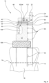
- the Figure 5 shows a longitudinal section through the shaft locking of Fig.1 .
- the hollow cylindrical rotor part 12 of the shaft lock 10 is connected to the shaft 16 having the axis of rotation 14 in a rotationally and slidingly fixed manner by means of a screw clamp coupling 106, which is only indicated in the drawing.
- the rotor part 12 has a circumferential annular groove 108 with an approximately trough-shaped cross-sectional geometry to save weight.
- the receiving geometry 46 is formed with a longitudinal groove 110 that is open on both sides or axially continuous, so that the shaft lock 10 only enables the rotationally fixed locking of the shaft 16 with the rotor part 12 within the radially outer stator part 20, whereas a displacement-proof blocking of the shaft 16 is not provided.
- the stator part 20 also has the radially outward-facing fastening flange 22 with a plurality of holes running parallel to the axis of rotation 16 and evenly spaced from one another on the circumference, of which only one hole 24 for the mechanical connection of the shaft lock 10 to an abutment (not shown) is shown and designated as representative of all the others.
- the holding element 82 designed as a permanent magnet 84, is fastened in a blind bore 112 directed essentially radially inwards within the locking ring 60. Accordingly, the locking ring 60 has an additional permanent magnet as a holding element for each additional locking body not shown here.
- the essentially cylindrical locking body 40 shown with a solid black line, is attracted by the permanent magnet 84 and is thereby securely fixed in position within the associated receiving pocket 72.
- the locking body 40 rests against the groove-like end section 80 of the receiving pocket 72, so that the locking body 40 is only partially received in the opening 56 of the stator part 20 and the receiving geometry 46 is completely free of the locking body 40.
- the locking body 40 is located radially outward in relation to the cylindrical inner surface 98 of the stator part 20, so that the rotor part 12 can rotate with practically no resistance in relation to the stationary stator part 20.
- the openings 56 here have an approximately oval slot geometry, since the locking bodies have a substantially cylindrical shape, so that the locking bodies can move within the openings of the stator part 20 essentially only radially inwards and outwards in relation to the axis of rotation 14. Axial movements, shear movements and/or tilting movements of the locking bodies in relation to the stator part 20 are essentially excluded due to the guidance in the openings of the stator part 20.
- the locking body 40 is displaced radially inward by rotating the locking ring 60 - as is graphically indicated by the black dotted outline representation 120 - it partially engages the receiving geometry 46 of the rotor part 12 and the desired positive connection 30 between the stator part 20 and the rotor part 12 of the shaft 16 is established and the shaft lock 10 has assumed the locking state.
Landscapes
- Engineering & Computer Science (AREA)
- General Engineering & Computer Science (AREA)
- Mechanical Engineering (AREA)
- Lock And Its Accessories (AREA)
- Mutual Connection Of Rods And Tubes (AREA)
- Braking Arrangements (AREA)
- Iron Core Of Rotating Electric Machines (AREA)
Description
- Die Erfindung betrifft eine Wellenverriegelung mit einem radial innenliegenden Rotorteil, das zentrisch mit einer eine Drehachse aufweisenden Welle verbunden ist, wobei die Welle und das radial innenliegende Rotorteil zumindest teilweise koaxial von einem feststehenden sowie radial außenliegenden Statorteil umschlossen sind.
- Aus dem Stand der Technik sind Verriegelungen in einer großen Variationsbreite bekannt, um eine Drehbewegung einer Welle erforderlichenfalls zu blockieren und im Bedarfsfall wieder freizugeben. Hierbei findet beispielsweise eine mechanische Verriegelung mittels zusätzlicher hydraulischer Verriegelungszylinder Verwendung. Weiterhin sind kraftschlüssige bzw. reibschlüssige Drehverriegelungen mittels ausfahrbarer Gewindestangen und Bremsscheiben bekannt. Darüber hinaus kommen formschlüssige Drehverriegelungen mittels Steckbolzen, ausfahrbaren Keilen, Riegeln, Stiften sowie Verzahnungen zum Einsatz. Weiterhin sind Drehverriegelungen einer Welle mit Hilfe von selbsthemmenden Getrieben, wie zum Beispiel Schraubengetrieben, bekannt.
- Druckschriftlicher Stand der Technik ist aus der
US 4 102 154 A bekannt. Diese Druckschrift zeigt eine Wellenverriegelung mit einem radial inneren Rotorteil, das zentrisch mit einer Welle verbunden werden kann. Das innere Rotorteil ist von einem äußeren Statorteil umgriffen. Mittels Verriegelungskörpern kann ein Formschluss zwischen dem Rotorteil und dem Statorteil hergestellt werden. Weiterer druckschriftlicher Stand der Technik ist in derWO 2018/144185 A1 und in derCN 101 639 103 A gezeigt. - Eine Aufgabe der Erfindung ist es unter anderem, eine konstruktiv einfach aufgebaute, räumlich kompakte Wellenverriegelung unter weitgehender Verwendung von Standard-Maschinenbauelementen anzugeben, die eine Übertragung hoher mechanischer Momente bei einem minimalen Drehspiel ermöglicht.
- Die eingangs genannte Aufgabe wird gelöst durch eine Wellenverriegelung mit den Merkmalen des Patentanspruchs 1, insbesondere dadurch, dass in einem Verriegelungszustand und in einem Haltezustand eine formschlüssige Verbindung mittels einer Mehrzahl von Verriegelungskörpern zwischen dem radial innenliegenden Rotorteil und dem feststehenden sowie radial außenliegenden Statorteil herstellbar ist und die formschlüssige Verbindung zum Übergang in einen Entriegelungszustand aufhebbar ist.
- Die Verriegelungskörper sind mittels mindestens eines Betätigungsglieds bereichsweise formschlüssig in jeweils eine Aufnahmegeometrie des radial innenliegenden Rotorteils zum Herstellen oder Aufheben der formschlüssigen Verbindung teilweise einrückbar. Infolgedessen ist eine Formschlussverbindung zwischen dem Rotorteil, den Verrieglungskörpern und dem Statorteil herstellbar und gegebenenfalls wieder lösbar. Im Fall von beispielhaft kugelförmigen Verriegelungskörpern sind die Aufnahmegeometrien als kalottenförmige Vertiefungen und im Fall von exemplarisch zylindrischen bzw. walzenförmigen Verriegelungskörpern als axiale Längsnuten ausgeführt. Sowohl die kalottenförmigen Vertiefungen als auch die Längsnuten weisen jeweils eine im Wesentlichen kreisabschnittförmige Querschnittsgeometrie auf, in die die Verriegelungskörper höchstens hälftig formschlüssig einrückbar sind.
- Das mindestens eine Betätigungsglied ist als ein im Wesentlichen hohlzylindrischer Verriegelungsring ausgebildet, der das feststehende sowie radial innenliegende Statorteil teilweise radial außenliegend koaxial umschließt. Hierdurch ist ein besonders platzsparender, robuster sowie kostengünstig zu fertigender Aufbau der Wellenverriegelung gewährleistet.
- Infolgedessen sind zumindest das Blockieren bzw. das Verriegeln sowie das erneute Freigeben einer Drehbewegung der Welle möglich. Erforderlichenfalls ist auch eine axiale Verriegelung der Welle realisierbar. Darüber hinaus sind mittels der kompakten und robusten Wellenverriegelung hohe Drehmomente bei einem geringen Einbauraumbedarf übertragbar. Durch die Formschlussverbindung besteht keinerlei Energiebedarf im Haltezustand, im Verriegelungszustand oder im Entriegelungszustand. Der Einsatz von Energie ist lediglich beim Umschalten zwischen den drei Zuständen der Wellenverriegelung vonnöten. Eine Drehwinkelposition des Verriegelungs- bzw. Haltezustands der Wellenverriegelung lässt sich bei der Montage der Zielanwendung frei festlegen. Hierbei lässt sich die Drehwinkelposition in einer sehr feinen, vorab konstruktiv leicht festlegbaren Teilung anpassen. Die erfindungsgemäße Wellenverriegelung ist im Entriegelungszustand kontaktfrei und tolerant gegenüber Schiefstellungen in der Form von Radial- und Winkelversätzen. Ferner entsteht aufgrund der Kontaktfreiheit im Entriegelungszustand keine betriebsbedingte Abwärme. Weiterhin ist ein geringes Verdrehspiel im Halte- und Verriegelungszustand gewährleistet. Die Wellenverriegelung kann dabei mit üblichen Standardelementen des Maschinenbaus kostengünstig gefertigt werden.
- Vorzugsweise ist die formschlüssige Verbindung zwischen dem feststehenden sowie radial außenliegenden Statorteil und dem Rotorteil mit der Welle drehfest oder drehfest und schiebefest ausgebildet. Infolgedessen lässt sich die Welle zusätzlich in axialer Richtung in Bezug zu dem radial außenliegenden Statorteil arretieren.
- Bei einer technisch vorteilhaften Ausgestaltung sind die Verriegelungskörper vorzugsweise umfangsseitig gleichmäßig verteilt positioniert.
- Hierdurch stellt sich eine gleichmäßige Kraft- und Momentenverteilung innerhalb der Wellenverriegelung ein.
- Im Fall einer weiteren vorteilhaften Ausgestaltung sind die Verriegelungskörper zylindrisch oder kugelförmig ausgebildet. Infolgedessen lässt sich die Wellenverriegelung flüssig und leichtgängig zwischen dem Entriegelungszustand, dem Verriegelungszustand und dem Haltezustand umschalten. Darüber hinaus stellen oberflächenveredelte Zylinder bzw. Rollen oder Kugeln besonders kostengünstige Standardbauelemente des Maschinenbaus dar.
- Bei einer vorteilhaften Formgebung ist vorgesehen, dass die Aufnahmegeometrien des radial innenliegenden Rotorteils jeweils eine Querschnittsform aufweisen, die näherungsweise einem Kreisabschnitt entspricht, dessen Höhe kleiner als ein Radius der Verriegelungskörper ist.
- Infolgedessen können sich die Verriegelungskörper beim Wechsel in den Entriegelungszustand wieder leicht vom Rotorteil abheben, da eine Äquatorialebene bzw. eine Mittelebene der Verriegelungskörper oberhalb einer Außenmantelfläche des Rotorteils verläuft. Infolgedessen sind die Verriegelungskörper unter keinen Umständen mehr als hälftig in die jeweils zugeordnete Aufnahmegeometrie des Rotorteils einrückbar.
- Bei einer technisch günstigen Weiterbildung weist das feststehende sowie radial innenliegende Statorteil eine Mehrzahl von radial durchgehenden Durchbrüchen auf, wobei in jedem Durchbruch jeweils ein Verriegelungskörper bereichsweise formschlüssig aufgenommen ist. Infolgedessen lassen sich die Verriegelungskörper mittels des Verriegelungsrings von außen mit Hilfe des Verriegelungsrings betätigen und somit radial einwärts gerichtet einrücken.
- Nach Maßgabe einer weiteren vorteilhaften Ausgestaltung weist eine zylindrische Innenfläche des Verriegelungsrings eine Mehrzahl von radial einwärts gerichteten Aufnahmetaschen für jeweils einen Verriegelungskörper auf, wobei jede Aufnahmetasche eine radial einwärts geneigte Anlaufschräge aufweist.
- Hierdurch ist eine radial einwärts gerichtete Verschiebebewegung der Verriegelungskörper mit einer hohen axialen Kraftwirkung durch das Verdrehen des Verriegelungsrings realisierbar.
- Vorzugsweise schließt an jede Anlaufschräge ein vertiefter, hohlkehlartiger Endabschnitt an, in dessen Bereich ein Halteelement, insbesondere ein Permanentmagnet, zur Lagefixierung eines Verriegelungskörpers innerhalb einer jeweils zugeordneten Aufnahmetasche des Verriegelungsrings in dem Entriegelungszustand angeordnet ist. Hierdurch sind im Entriegelungszustand der Wellenverriegelung eine zuverlässige Lagesicherung und eine definierte Lage der Verriegelungskörper gewährleistet.
- Bei einer vorteilhaften Weiterbildung ist vorgesehen, dass jede Anlaufschräge einen umfangsseitig von dem vertieften hohlkehlartigen Endabschnitt weggerichteten weiteren Endabschnitt aufweist, an den umfangsseitig eine konzentrisch zur Drehachse ausgeführte Haltefläche anschließt.
- Aufgrund der im Wesentlichen tangential in Bezug zur Innenfläche des Verriegelungsrings verlaufenden Halteflächen der Anlaufschrägen ist eine umfangsseitige Verschiebung der Verriegelungskörper ausgeschlossen, so dass sich die Wellenverriegelung nicht unbeabsichtigt lösen kann.
- Bevorzugt ist jeder Verriegelungskörper im Entriegelungszustand der Wellenverriegelung jeweils von einem Halteelement in dem jeweils zugeordneten vertieften hohlkehlartigen Endabschnitt der Anlaufschräge gehalten, so dass die Aufnahmegeometrien des Rotorteils frei von Verriegelungskörpern sind und die Verriegelungskörper soweit radial außen liegen, dass sie höchstens bündig mit einer zylindrischen Innenfläche des Statorteils abschließen und sich das Rotorteil zusammen mit der Welle frei in Relation zum Statorteil drehen kann. Hierdurch ist die mechanische Kontaktfreiheit bzw. die Reibungsfreiheit zwischen dem Rotorteil und dem Statorteil im Entriegelungszustand der Wellenverriegelung sichergestellt.
- Bei einer weiteren Ausgestaltung der Wellenverriegelung ist vorgesehen, dass durch das Verdrehen des Verriegelungsrings in einer Verriegelungsrichtung die Verriegelungskörper mittels der Anlaufschrägen aus den Durchbrüchen des Statorteils radial einwärts verschiebbar sind und hierbei weniger als hälftig in jeweils eine zugeordnete Aufnahmegeometrie des Rotorteils einrückbar sind und der Verriegelungszustand der Wellenverriegelung hergestellt ist, in dem eine Verdrehung des Rotorteils mit der Welle in Relation zum Statorteil blockiert ist.
- Hierdurch ist eine robuste und zudem mechanisch hoch belastbare Blockierung einer Drehbewegung der Welle mit dem Rotorteil in Relation zu dem Statorteil gegeben.
- Vorzugsweise kommt bei einem weiteren Verdrehen des Verriegelungsrings in der Verriegelungsrichtung jeder Verriegelungskörper zur Anlage an die jeweils zugeordnete Haltefläche der Aufnahmetasche und der Haltezustand der Wellenverriegelung ist erreicht, in dem ein unbeabsichtigtes Lösen der formschlüssigen Verbindung zwischen dem Rotorteil mit der Welle und dem Statorteil ausgeschlossen ist. Hierdurch ist im Haltezustand ein unbeabsichtigtes Lösen der Blockierung der Welle zuverlässig ausgeschlossen.
- Im Folgenden wird ein bevorzugtes Ausführungsbeispiel der Erfindung anhand von schematischen Figuren näher erläutert.
- Es zeigen
- Figur 1
- eine teilweise angeschnittene Teildraufsicht einer erfindungsgemäßen Wellenverriegelung in einem Entriegelungszustand,
- Figur 2
- eine teilweise angeschnittene Teildraufsicht der Wellenverriegelung von
Figur 1 in einem Verriegelungszustand, - Figur 3
- eine teilweise angeschnittene Teildraufsicht der Wellenverriegelung von
Figur 1 in einem Haltezustand, - Figur 4
- eine vergrößerte schematische Darstellung einer Querschnittsgeometrie einer Aufnahmegeometrie eines Rotorteils mit einem darin bereichsweise formschlüssig aufgenommenen zylindrischen Verriegelungskörper, und
- Figur 5
- einen Längsschnitt durch die Wellenverriegelung von
Figur 1 . - Die
Figur 1 zeigt eine teilweise angeschnittene Teildraufsicht einer erfindungsgemäßen Wellenverriegelung in einem Entriegelungszustand. Eine Wellenverriegelung 10 umfasst zunächst ein radial innenliegendes Rotorteil 12, das zentrisch mit einer eine Drehachse 14 aufweisenden Welle 16 verbunden ist. Die mechanisch hochfeste Verbindung zwischen der Welle 16 und dem Rotorteil 12 der Wellenverriegelung 10 kann zum Beispiel mit Hilfe einer hier nicht dargestellten Schraub-Klemmkupplung, durch thermisches Aufschrumpfen, eine Passfederverbindung oder dergleichen realisiert sein. Das Rotorteil 12 verfügt über eine im Wesentlichen hohlzylindrische Geometrie. Die Welle 16 mit dem darauf befestigten, radial innenliegenden Rotorteil 12 ist zumindest teilweise koaxial von einem feststehenden bzw. ortsfesten sowie radial außenliegenden Statorteil 20 umschlossen. Das eine gleichfalls im Wesentlichen hohlzylindrische Geometrie aufweisende Statorteil 20 weist einen radial auswärts gerichteten bzw. senkrecht zur Drehachse 14 orientierten, kreisringförmigen Befestigungsflansch 22 auf. In den Befestigungsflansch 22 ist eine Vielzahl von bevorzugt umfangsseitig gleichmäßig zueinander beabstandet angeordneten Durchgangsbohrungen 24 für Befestigungsmittel 26, wie Schrauben, Bolzen etc. eingebracht. Durch die Befestigungsmittel 26 ist der Statorteil 20 mit einem nicht dargestellten ortsfesten Widerlager, wie zum Beispiel einer Rumpfstruktur eines Schiffes, einem Getriebeflansch oder dergleichen verbunden. - In einem Verriegelungszustand sowie in einem Haltezustand der Wellenverriegelung 10 besteht eine formschlüssige Verbindung (vgl. Figur 2, 3; Bezugsziffer 30) mittels einer Mehrzahl von bevorzugt umfangsseitig gleichmäßig zueinander beabstandet angeordneten Verriegelungskörpern 40 zwischen dem radial innenliegenden Rotorteil 12 und dem feststehenden und radial außen positionierten Statorteil 20. In der Darstellung von der
Figur 1 befindet sich die Wellenverriegelung 10 in einem Entriegelungszustand, in dem die formschlüssige Verbindung zwischen dem Rotorteil 12 und dem Statorteil 20 aufgehoben ist und sich die Welle 16 mit dem Rotorteil 12 frei und praktisch widerstandsfrei in Relation zu dem Statorteil 20 verdrehen kann. Die formschlüssige Verbindung zwischen dem feststehenden und dem radial außenliegenden Statorteil 20 und dem Rotorteil 12 kann hierbei drehfest oder auch drehfest und schiebefest ausgebildet sein. - Die konstruktiv identischen Verriegelungskörper 40 sind mittels mindestens eines Betätigungsglieds 44 in jeweils eine zugeordnete periphere Aufnahmegeometrie 46 einer Außenmantelfläche 48 des Rotorteils 12 zum Herstellen oder Aufheben der formschlüssigen Verbindung höchstens teilweise eindrückbar. Die Verriegelungskörper 40 können beispielsweise kugelförmig oder im Wesentlichen zylinder- bzw. walzenförmig oder rollenförmig ausgeführt sein. Die Verriegelungskörper 40 können auch eine vieleckige Querschnittsgeometrie aufweisen und zum Beispiel nach Art von Passfedern ausgebildet sein. In Abhängigkeit von der Formgebung der Verriegelungskörper 40 können die konstruktiv jeweils gleichen Aufnahmegeometrien 46 des Rotorteils 12 beispielsweise als kalottenförmige Vertiefungen oder als Längsnuten in der Außenmantelfläche 48 des Rotorteils 12 ausgeführt sein. In dem hier illustrierten Ausführungsbeispiel der Wellenverriegelung 10 sind die Verriegelungskörper 40 lediglich zylindrisch bzw. walzenförmig ausgestaltet, woraus im Vergleich zu kugelförmigen Verriegelungskörpern eine reduzierte Flächenpressung bei einer Überleitung hoher Drehmomente über die Wellenverriegelung 10 zu erzielen ist. Demzufolge sind die Aufnahmegeometrien 46 hier als parallel zur Drehachse 14 verlaufende, der besseren zeichnerischen Übersicht halber nicht bezeichnete Längsnuten, ausgeführt. In Abhängigkeit davon, ob zusätzlich eine einseitig oder beidseitig axial verschiebefeste Verriegelung der Welle 16 erwünscht ist, können die Längsnuten axial durchgehend bzw. beidseitig offen oder einseitig oder beidseitig geschlossen ausgeführt sein. Zur bereichsweise formschlüssigen Aufnahme weisen die Längsnuten eine Querschnittsgeometrie auf, die im Wesentlichen der eines Kreisabschnitts entspricht bzw. die komplementär zur Querschnittsgeometrie der Verriegelungskörper 40 ausgeführt ist.
- Sowohl im Verriegelungszustand als auch im Haltezustand der Wellenverriegelung 10 ist jeweils ein Verriegelungskörper 40 bereichsweise formschlüssig in jeweils einer Aufnahmegeometrie 46 des Rotorteils 12 aufgenommen. Die Aufnahmegeometrien 46 des Rotorteils 12 weisen jeweils eine Querschnittsform 50 auf, die näherungsweise einem hier nicht bezeichneten Kreisabschnitt bzw. Kreissegment entspricht, dessen hier gleichfalls nicht bezeichnete Höhe kleiner als ein hier ebenfalls nicht mit einer Bezugsziffer versehener Radius der Verriegelungskörper 40 ist, so dass sich die Verriegelungskörper 40 aufgrund der dann nicht vorhandenen Hinterschneidung leicht radial auswärts aus den Aufnahmegeometrien 46 herausbewegen lassen (vgl.
Figur 4 ) . - Das Statorteil 20 verfügt über eine Vielzahl von radial durchgehenden, konstruktiv identischen Durchbrüchen 56, die umfangsseitig gleichmäßig zueinander beabstandet angeordnet sind und die - wie hier gezeigt - zumindest für den Übergang vom Entriegelungszustand in den Verriegelungszustand oder Haltezustand umfangsseitig vollständig in Deckung mit den jeweils zugeordneten Aufnahmegeometrien 46 des Rotorteils 12 stehen.
- In jedem der Durchbrüche 56 des Statorteils 20 ist jeweils ein Verriegelungskörper 40 zumindest bereichsweise formschlüssig aufgenommen. In Abhängigkeit davon, ob die Verriegelungskörper 40 kugelförmig oder zylinderförmig ausgestaltet sind, sind die Durchbrüche 56 als radial durchgehende Bohrungen oder als parallel zur Drehachse 14 verlaufende Langlöcher bzw. Längsschlitze ausgeführt.
- Das Betätigungsglied 44 ist hier lediglich beispielhaft mit einem im Wesentlichen hohlzylindrischen Verriegelungsring 60 gebildet, der das feststehende und radial innenliegende Statorteil 20 teilweise radial außenliegend koaxial umschließt. Zum Wechsel von dem in
Figur 1 gezeigten Entriegelungszustand in den Verriegelungszustand oder in den Haltezustand der Wellenverriegelung 10 (vgl.Figuren 2 ,3 ), ist der Verriegelungsring 60 mittels eines geeigneten, zeichnerisch lediglich angedeuteten Aktors 62 in einer Verriegelungsrichtung 64 verdrehbar. Durch das Verdrehen des Verriegelungsrings 60 in einer der Verriegelungsrichtung 64 entgegengesetzt orientierten, nicht eingezeichneten Entriegelungsrichtung, erfolgt im Bedarfsfall der Wechsel aus dem Haltezustand in den Entriegelungszustand. - In eine zylindrische Innenfläche 70 des Verriegelungsrings 60 ist eine Vielzahl von radial einwärts gerichteten, konstruktiv jeweils gleichartigen Aufnahmetaschen 72 für jeweils einen Verriegelungskörper 40 eingelassen, wobei jede Aufnahmetasche 72 eine radial einwärts gerichtete Anlaufschräge 74 aufweist. Jede Anlaufschräge 74 verfügt über einen vertieften, hohlkehlartigen Endabschnitt 80, in dem im hier gezeigten Entriegelungszustand der Wellenverriegelung 10 jeweils ein Verriegelungskörper 40 bereichsweise anliegt. Um die Verriegelungskörper 40 im Entriegelungszustand zuverlässig in dem ihnen jeweils zugeordneten hohlkehlartigen Endabschnitt 80 zu halten, ist im Bereich eines jeden hohlkehlartigen Endabschnitts 80 jeweils ein Halteelement 82 vorgesehen. Dasselbe gilt für alle weiteren nicht dargestellten hohlkehlartigen Endabschnitte der übrigen Aufnahmetaschen. Die Halteelemente 82 sind bevorzugt jeweils mit einem Permanentmagneten 84 realisiert. Alternativ können auch mechanische Halteelemente, wie zum Beispiel Halteklammern etc. vorgesehen sein. Jede Anlaufschräge 74 weist ferner einen umfangsseitig, von dem jeweils zugeordneten, hohlkehlartig vertieften Endabschnitt 80 weggerichteten weiteren Endabschnitt 90 auf, an den sich umfangseitig jeweils eine konzentrisch zu der Drehachse 14 ausgeführte Haltefläche 92 anschließt.
- Die Halteflächen 92 verlaufen hier lediglich exemplarisch im Wesentlichen tangential zu der - bis auf die Aufnahmetaschen - näherungsweise zylindrischen Innenfläche 70 des Verriegelungsrings 60. Die Halteflächen 92 können gegebenenfalls auch coradial, also zylindrisch in Bezug zu der Innenfläche 70 des Verriegelungsrings 60 ausgebildet sein.
- Jeder Verriegelungskörper 40 ist in dem hier illustrierten Entriegelungszustand der Wellenverriegelung 10 jeweils von einem zugeordneten Halteelement 82 in dem jeweils zugeordneten, vertieften hohlkehlartigen Endabschnitt 80 der betreffenden Anlaufschräge 74 zuverlässig gehalten. Infolgedessen sind die Aufnahmegeometrien 46 des Rotorteils 12 frei von Verriegelungskörpern 40 und diese liegen soweit radial außen, dass sie höchstens bündig mit einer zylindrischen Innenfläche 98 des Statorteils 20 abschließen bzw. innenseitig nicht über diese hinausragen, sodass sich das Rotorteil 12 zusammen mit der daran befestigten Welle 16 im Entriegelungszustand praktisch reibungsfrei in Relation zum Statorteil 20 drehen kann.
- Die
Figur 2 illustriert eine teilweise angeschnittene Teildraufsicht der Wellenverriegelung vonFigur 1 in einem Verriegelungszustand. Die Wellenverriegelung 10 umfasst wiederum das Rotorteil 12, das Statorteil 20 sowie das als Verriegelungsring 60 ausgebildete Betätigungsglied 44, die konzentrisch zur Drehachse 14 der Welle 16 angeordnet sind. Der Aktor vonFigur 1 ist der besseren zeichnerischen Übersicht hier und in allen weiteren Figuren nicht mehr dargestellt. Durch das Verdrehen des Verriegelungsrings 60 in Richtung der Verriegelungsrichtung 64 haben sich die Verriegelungskörper 40 aus den hohlkehlartigen Endabschnitten 80 der Aufnahmetaschen 72 des Verriegelungsrings 60 herausbewegt und sind auf den Anlaufschrägen 74 umfangsseitig bis an die Halteflächen 92 heran gelaufen. Aufgrund der radial einwärts gerichteten Neigung der Anlaufschrägen 74 erfolgt eine in Bezug zu der Drehachse 14 radial einwärts gerichtete Verschiebebewegung der Verriegelungskörper 40, sodass diese teilweise aus den Durchbrüchen 56 des Statorteils 20 heraus geschoben und in die jeweils zugeordnete Aufnahmegeometrie 46 des Rotorteils 12 eingerückt werden, wodurch die formschlüssige Verbindung 30 zwischen dem Rotorteil 12 und dem Statorteil 20 geschaffen wird. - Eine Äquatorialebene 100 der Verriegelungskörper 40 verbleibt stets radial außerhalb bzw. radial oberhalb der Außenmantelfläche 48 des Rotorteils 12, so dass sich die Verriegelungskörper 40 bei einem Wechsel in den Entriegelungszustand von
Figur 1 leicht aus den Aufnahmegeometrien 46 des Rotorteils 12 herausbewegen können. Dies wird dadurch erreicht, dass die Querschnittsform 50 der Aufnahmegeometrien 46 jeweils kleiner als ein Halbkreis ist bzw. die Form eines Kreisabschnitts aufweist. - Durch das Verdrehen des Verriegelungsrings 60 in der Verriegelungsrichtung 64 sind die Verriegelungskörper 40 mithilfe der Anlaufschrägen 74 aus den Durchbrüchen 56 des Statorteils 20 in Bezug zur Drehachse 14 radial einwärts verschiebbar, so dass die Verriegelungskörper 40 weniger als hälftig in jeweils einer zugeordneten Aufnahmegeometrie 46 des Rotorteils 12 eingerückt unter Schaffung der formschlüssigen Verbindung 30 sind und der Verriegelungszustand der Wellenverriegelung 10 erreicht ist. In dem Verriegelungszustand ist jede Verdrehung des Rotorteils 12 mit der Welle 16 in Relation zum Statorteil 20 auch beim Einwirken hoher und höchster Drehmomente zuverlässig blockiert.
- Die
Figur 3 zeigt eine teilweise angeschnittene Teildraufsicht der Wellenverriegelung vonFigur 1 in einem Haltezustand. - Die rotationssymmetrisch zur Drehachse 14 aufgebaute Wellenverriegelung 10 umfasst wiederum die Welle 16 mit dem darauf befestigten Rotorteil 12, das Statorteil 20 sowie das als Verriegelungsring 60 ausgeführte Betätigungsglied 44. Durch das Weiterdrehen des Verriegelungsrings 60 ausgehend von dem Verriegelungszustand in
Figur 2 in der Orientierung der Verriegelungsrichtung 64 gleiten die Verriegelungskörper 40 bis auf die Halteflächen 92 des weiteren Endabschnitts 90 der Anlaufschrägen 74 der Aufnahmetaschen 72 des Verriegelungsrings auf. Durch die im Wesentlichen koaxial zu der Drehachse 14 verlaufenden Halteflächen 92, der - bis auf die Aufnahmetaschen 72 - im Wesentlichen zylindrischen Innenfläche 70 des Verriegelungsrings 60, ist ein unbeabsichtigtes Umschalten der Wellenverriegelung 10 aus dem Haltezustand in den Verriegelungs- oder den Entriegelungszustand ausgeschlossen. Zusätzlich können die Halteflächen 92 jeweils mit einer zeichnerisch nicht dargestellten kleinen muldenartigen Vertiefung und/oder einer geringfügigen wulstartigen Aufdickung versehen sein, die eine Zurückbewegung der Verriegelungskörper 40 bis in den Bereich der jeweils zugeordneten Anlaufschräge 74 der Aufnahmetasche 72 ohne aktive Betätigung des Verriegelungsrings 60 verhindern, sodass eine selbsttätige Entriegelung der Wellenverriegelung 10 zuverlässig ausgeschlossen ist. Aufgrund optionaler Aufdickungen oder Vertiefungen vergrößert sich jedoch in der Regel das Spiel der Verriegelungskörper 40 und als Folge hiervon ein Verdrehspiel der verriegelten Welle 16. - Die Formschlussverbindung 30 zwischen dem Rotorteil 12 und dem Statorteil 20 bleibt im hier gezeigten Haltezustand der Wellenverriegelung 10 bis zum Verdrehen des Verriegelungsrings 60 entgegen der Verriegelungsrichtung 64 unverändert bestehen.
- Durch eine Drehbewegung des Verriegelungsrings 60 entgegen der Verriegelungsrichtung 64, kann die Wellenverriegelung ausgehend von dem hier illustrierten Haltezustand im Bedarfsfall wiederum in den Verriegelungszustand von
Figur 2 und durch Weiterdrehen in den Entriegelungszustand vonFigur 1 zurückversetzt werden. Zum Lösen der Verriegelungskörper 40 aus den diesen jeweils zugeordneten Aufnahmegeometrien 46 des Rotors 12, kann eine geringfügige und kurzzeitig anruckende Drehbewegung entgegen oder in Richtung der Orientierung der Verriegelungsrichtung 64 zwischen dem Rotorteil 12 und dem Statorteil 20 erforderlich sein. Zum Lösen der Verriegelungskörper 40 muss der Verriegelungsring 60 grundsätzlich entgegen der Verriegelungsrichtung 64 bis in die Stellung vonFigur 1 verdreht bzw. "geöffnet" sein, so dass sich die Wellenverriegelung 10 wiederum im Entriegelungszustand befindet. - Die
Figur 4 zeigt eine vergrößerte schematische Querschnittsdarstellung einer Aufnahmegeometrie eines Rotorteils mit einem darin bereichsweise formschlüssig aufgenommenen zylindrischen Verriegelungskörper. - In das Rotorteil 12 ist eine Vielzahl von Aufnahmegeometrien für die Verriegelungskörper ausgebildet, von denen hier lediglich ein bereichsweise formschlüssig in der Aufnahmegeometrie 46 aufgenommener Verriegelungskörper 40 stellvertretend für alle weiteren Verriegelungskörper und Aufnahmegeometrien dargestellt ist. Der Verriegelungskörper 40 weist eine im Wesentlichen zylindrische Formgebung mit einem Radius R1 auf, wobei der Radius R1 mit einem Radius R2 der kalottenförmigen Aufnahmegeometrie 46 zur Gewährleistung der bereichsweisen Formschlüssigkeit korrespondiert. Die Aufnahmegeometrie 46 verfügt über eine Querschnittsform 50, die näherungsweise der eines Kreisabschnitts 102 bzw. der eines Kreissegments mit einer Höhe h entspricht. Die Äquatorialebene 100 bzw. die Mittelebene des Verriegelungskörpers 40 verläuft oberhalb bzw. radial auswärts in Bezug zu der Außenmantelfläche 48 des Rotorteils 12 bzw. der Drehachse 14, so dass der Verriegelungskörper 40 in jedem Fall weniger als zur Hälfte formschlüssig in der Aufnahmegeometrie 46 des Rotorteils 12 aufgenommen ist. Entsprechende Überlegungen gelten für den Fall, dass der Verriegelungskörper 40 kugelförmig ausgeführt ist.
- Die
Figur 5 zeigt einen Längsschnitt durch die Wellenverriegelung vonFig. 1 . - Das hohlzylindrische Rotorteil 12 der Wellenverriegelung 10 ist mittels einer zeichnerisch lediglich angedeuteten Schraub-Klemmkupplung 106 dreh- und schiebefest mit der die Drehachse 14 aufweisenden Welle 16 verbunden. Das Rotorteil 12 verfügt über eine umlaufende Ringnut 108 mit einer näherungsweise wannenförmigen Querschnittsgeometrie zur Gewichtseinsparung. An der Außenmantelfläche 48 des Rotorteils 12 sind die Aufnahmegeometrien ausgebildet, von denen hier lediglich eine Aufnahmegeometrie 46 dargestellt ist. In dem hier dargestellten Ausführungsbeispiel ist die Aufnahmegeometrie 46 mit einer beidseitig offenen bzw. axial durchgehenden Längsnut 110 gebildet, sodass die Wellenverriegelung 10 nur das drehfeste Arretieren der Welle 16 mit dem Rotorteil 12 innerhalb des radial außenliegenden Statorteils 20 ermöglicht, wohingegen eine verschiebefeste Blockierung der Welle 16 nicht vorgesehen ist. Das Statorteil 20 verfügt ferner über den radial auswärts gerichteten Befestigungsflansch 22 mit einer Vielzahl von parallel zur Drehachse 16 verlaufenden sowie umfangsseitig gleichmäßig zueinander beabstandeten Bohrungen, von denen lediglich eine Bohrung 24 zur mechanischen Anbindung der Wellenverriegelung 10 an ein nicht dargestelltes Widerlager repräsentativ für alle übrigen dargestellt und bezeichnet ist. Das als Permanentmagnet 84 ausgebildete Halteelement 82 ist in einer im Wesentlichen radial einwärts gerichteten Sackbohrung 112 innerhalb des Verriegelungsrings 60 befestigt. Entsprechend weist der Verriegelungsring 60 für jeden weiteren hier nicht dargestellten Verriegelungskörper einen weiteren Permanentmagneten als Halteelement auf. In dem hier veranschaulichten Entriegelungszustand der Wellenverriegelung 10 wird der mit einer durchgezogenen schwarzen Linie dargestellte, im Wesentlichen zylinderförmige Verriegelungskörper 40 von dem Permanentmagneten 84 angezogen und ist hierdurch sicher innerhalb der zugeordneten Aufnahmetasche 72 lagefixiert. Der Verriegelungskörper 40 liegt an dem hohlkehlartigen Endabschnitt 80 der Aufnahmetasche 72 an, so dass der Verriegelungskörper 40 nur teilweise in dem Durchbruch 56 des Statorteils 20 aufgenommen ist und die Aufnahmegeometrie 46 vollkommen frei von dem Verriegelungskörper 40 ist. Der Verriegelungskörper 40 liegt radial auswärts in Bezug zur zylindrischen Innenfläche 98 des Statorteils 20, sodass sich der Rotorteil 12 praktisch widerstandsfrei in Relation zu dem ortsfesten Statorteil 20 verdrehen kann. Die Durchbrüche 56 weisen hier eine näherungsweise ovale Langlochgeometrie auf, da die Verriegelungskörper eine im Wesentlichen zylindrische Formgebung aufweisen, so dass sich die Verriegelungskörper innerhalb der Durchbrüche des Statorteils 20 im Wesentlichen nur radial einwärts und auswärts in Bezug zu der Drehachse 14 verschieben können. Axiale Bewegungen, Scherbewegungen und/oder Kippbewegungen der Verriegelungskörper in Bezug zum Statorteil 20 sind aufgrund der Führung in den Durchbrüchen des Statorteils 20 im Wesentlichen ausgeschlossen.
- Wird der Verriegelungskörper 40 durch das Verdrehen des Verriegelungsrings 60 radial einwärts - wie mit der schwarzen punktierten Umrissdarstellung 120 zeichnerisch angedeutet ist - verschoben, so rückt dieser teilweise in die Aufnahmegeometrie 46 des Rotorteils 12 ein und die gewünschte formschlüssige Verbindung 30 zwischen dem Statorteil 20 sowie dem Rotorteil 12 der Welle 16 ist hergestellt und die Wellenverriegelung 10 hat den Verriegelungszustand eingenommen.
- Durch das zumindest geringfügige Weiterdrehen des Verriegelungsring 60 in der gleichen Richtung wird die Wellenverriegelung 10 ausgehend von dem Verriegelungszustand weiter in den Haltezustand versetzt.
-
- 10
- Wellenverriegelung
- 12
- Rotorteil
- 14
- Drehachse
- 16
- Welle
- 20
- Statorteil
- 22
- Befestigungsflansch
- 24
- Durchgangsbohrung
- 26
- Befestigungsmittel
- 30
- formschlüssige Verbindung
- 40
- Verriegelungskörper
- 44
- Betätigungsglied
- 46
- Aufnahmegeometrie (Rotorteil)
- 48
- Außenmantelfläche (Rotorteil)
- 50
- Querschnittsform (Aufnahmegeometrie Rotorteil)
- 56
- Durchbruch (Statorteil)
- 60
- Verriegelungsring
- 62
- Aktor
- 64
- Verriegelungsrichtung
- 70
- zylindrische Innenfläche (Verriegelungsring)
- 72
- Aufnahmetasche
- 74
- Anlaufschräge
- 80
- hohlkehlartiger Endabschnitt (Anlaufschräge)
- 82
- Halteelement
- 84
- Permanentmagnet
- 90
- weiterer Endabschnitt (Anlaufschräge)
- 92
- Haltefläche
- 98
- zylindrische Innenfläche (Statorteil)
- 100
- Äquatorialebene (Mittelebene Verriegelungskörper)
- 102
- Kreisabschnitt
- 106
- Schraub-Klemmkupplung
- 108
- Ringnut
- 110
- Längsnut (Rotorteil)
- 112
- Sackbohrung
- 120
- Umrissdarstellung (Verriegelungskörper)
- R1
- Radius (Verriegelungskörper)
- R2
- Radius (Aufnahmegeometrie Rotorteil)
- h
- Höhe (Kreisabschnitt Aufnahmegeometrie)
Claims (12)
- Wellenverriegelung (10) mit einem radial innenliegenden Rotorteil (12), das zentrisch mit einer eine Drehachse (14) aufweisenden Welle (16) verbunden ist, wobei die Welle (16) und das radial innenliegende Rotorteil (12) zumindest teilweise koaxial von einem feststehenden sowie radial außenliegenden Statorteil (20) umschlossen sind, wobei in einem Verriegelungszustand und in einem Haltezustand eine formschlüssige Verbindung (30) mittels einer Mehrzahl von Verriegelungskörpern (40) zwischen dem radial innenliegenden Rotorteil (12) und dem feststehenden sowie radial außenliegenden Statorteil (20) herstellbar ist und die formschlüssige Verbindung (30) zum Übergang in einen Entriegelungszustand aufhebbar ist, und wobei die Verriegelungskörper (40) mittels mindestens eines Betätigungsglieds (44) bereichsweise formschlüssig in jeweils eine Aufnahmegeometrie (46) des radial innenliegenden Rotorteils (12) zum Herstellen oder Aufheben der formschlüssigen Verbindung (30) teilweise einrückbar sind, dadurch gekennzeichnet, dass das mindestens eine Betätigungsglied (44) als ein im Wesentlichen hohlzylindrischer Verriegelungsring (60) ausgebildet ist, der das feststehende sowie radial innenliegende Statorteil (20) teilweise radial außenliegend koaxial umschließt.
- Wellenverriegelung (10) nach Patentanspruch 1, dadurch gekennzeichnet, dass die formschlüssige Verbindung (30) zwischen dem feststehenden sowie radial außenliegenden Statorteil (20) und dem Rotorteil (12) mit der Welle (16) drehfest oder drehfest und schiebefest ausgebildet ist.
- Wellenverriegelung (10) nach Patentanspruch 1 oder 2, dadurch gekennzeichnet, dass die Verriegelungskörper (40) vorzugsweise umfangsseitig gleichmäßig verteilt positioniert sind.
- Wellenverriegelung (10) nach Patentanspruch1, 2 oder 3, dadurch gekennzeichnet, dass die Verriegelungskörper (40) zylindrisch oder kugelförmig ausgebildet sind
- Wellenverriegelung (10) nach einem der vorhergehenden Patentansprüche, dadurch gekennzeichnet, dass die Aufnahmegeometrien (46) des radial innenliegenden Rotorteils (12) jeweils eine Querschnittsform (50) aufweisen, die näherungsweise einem Kreisabschnitt entspricht, dessen Höhe (h) kleiner als ein Radius (R1) der Verriegelungskörper (40) ist.
- Wellenverriegelung (10) nach einem der vorhergehenden Patentansprüche, dadurch gekennzeichnet, dass das feststehende sowie radial innenliegende Statorteil (20) eine Mehrzahl von radial durchgehenden Durchbrüchen (56) aufweist, wobei in jedem Durchbruch (56) jeweils ein Verriegelungskörper (40) bereichsweise formschlüssig aufgenommen ist.
- Wellenverriegelung (10) nach einem der vorhergehenden Patentansprüche, dadurch gekennzeichnet, dass eine zylindrische Innenfläche (70) des Verriegelungsrings (60) eine Mehrzahl von radial einwärts gerichteten Aufnahmetaschen (72) für jeweils einen Verriegelungskörper (40) aufweist, wobei jede Aufnahmetasche (72) eine radial einwärts geneigte Anlaufschräge (74) aufweist.
- Wellenverriegelung (10) nach Patentanspruch 7, dadurch gekennzeichnet, dass an jede Anlaufschräge (74) ein vertiefter, hohlkehlartiger Endabschnitt (80) anschließt, in dessen Bereich ein Halteelement (82), insbesondere ein Permanentmagnet (84), zur Lagefixierung eines Verriegelungskörpers (40) innerhalb einer jeweils zugeordneten Aufnahmetasche (72) des Verriegelungsrings (60) in dem Entriegelungszustand angeordnet ist.
- Wellenverriegelung (10) nach Patentanspruch 7 oder 8, dadurch gekennzeichnet, dass jede Anlaufschräge (74) einen umfangsseitig von dem vertieften hohlkehlartigen Endabschnitt (80) weggerichteten weiteren Endabschnitt (90) aufweist, an den umfangsseitig eine konzentrisch zur Drehachse (16) ausgeführte Haltefläche (92) anschließt.
- Wellenverriegelung (10) nach einem der Patentansprüche 4 bis 11, dadurch gekennzeichnet, dass jeder Verriegelungskörper (40) im Entriegelungszustand der Wellenverriegelung (10) jeweils von einem Halteelement (82) in dem jeweils zugeordneten vertieften hohlkehlartigen Endabschnitt (80) der Anlaufschräge (74) gehalten ist, so dass die Aufnahmegeometrien (46) des Rotorteils (12) frei von Verriegelungskörpern (40) sind und die Verriegelungskörper (40) soweit radial außen liegen, dass sie höchstens bündig mit einer zylindrischen Innenfläche (98) des Statorteils (20) abschließen und sich das Rotorteil (12) zusammen mit der Welle (14) frei in Relation zum Statorteil (20) drehen kann.
- Wellenverriegelung (10) nach einem der vorhergehenden Patentansprüche, dadurch gekennzeichnet, dass durch das Verdrehen des Verriegelungsrings (60) in einer Verriegelungsrichtung (64) die Verriegelungskörper (40) mittels der Anlaufschrägen (74) aus den Durchbrüchen (56) des Statorteils (20) radial einwärts verschiebbar sind und hierbei weniger als hälftig in jeweils eine zugeordnete Aufnahmegeometrie (46) des Rotorteils (12) einrückbar sind und der Verriegelungszustand der Wellenverriegelung (10) hergestellt ist, in dem eine Verdrehung des Rotorteils (12) mit der Welle (16) in Relation zum Statorteil (20) blockiert ist.
- Wellenverriegelung (10) nach einem der vorhergehenden Patentansprüche, dadurch gekennzeichnet, dass bei einem weiteren Verdrehen des Verriegelungsrings (60) in der Verriegelungsrichtung (64) jeder Verriegelungskörper (40) zur Anlage an die jeweils zugeordnete Haltefläche (92) der Aufnahmetasche (72) kommt und der Haltezustand der Wellenverriegelung (10) erreicht ist, in dem ein unbeabsichtigtes Lösen der formschlüssigen Verbindung (30) zwischen dem Rotorteil (12) mit der Welle (16) und dem Statorteil (20) ausgeschlossen ist.
Applications Claiming Priority (2)
| Application Number | Priority Date | Filing Date | Title |
|---|---|---|---|
| DE102019217384.5A DE102019217384A1 (de) | 2019-11-11 | 2019-11-11 | Wellenverriegelung |
| PCT/EP2020/081490 WO2021094254A1 (de) | 2019-11-11 | 2020-11-09 | Wellenverriegelung |
Publications (2)
| Publication Number | Publication Date |
|---|---|
| EP4058682A1 EP4058682A1 (de) | 2022-09-21 |
| EP4058682B1 true EP4058682B1 (de) | 2024-04-24 |
Family
ID=73198324
Family Applications (1)
| Application Number | Title | Priority Date | Filing Date |
|---|---|---|---|
| EP20803822.4A Active EP4058682B1 (de) | 2019-11-11 | 2020-11-09 | Wellenverriegelung |
Country Status (8)
| Country | Link |
|---|---|
| US (1) | US11796016B2 (de) |
| EP (1) | EP4058682B1 (de) |
| JP (1) | JP2023500885A (de) |
| KR (1) | KR20220092520A (de) |
| CN (1) | CN114746662A (de) |
| AU (1) | AU2020384645A1 (de) |
| DE (1) | DE102019217384A1 (de) |
| WO (1) | WO2021094254A1 (de) |
Families Citing this family (1)
| Publication number | Priority date | Publication date | Assignee | Title |
|---|---|---|---|---|
| KR102791834B1 (ko) * | 2023-07-18 | 2025-04-09 | 주식회사 뉴로메카 | 모터용 브레이크 조립체 |
Family Cites Families (10)
| Publication number | Priority date | Publication date | Assignee | Title |
|---|---|---|---|---|
| US3770086A (en) * | 1971-04-12 | 1973-11-06 | Eaton Corp | Hoist having yielding means for load limiting |
| US4102154A (en) | 1976-09-07 | 1978-07-25 | Dahlstrand Jr Josef | Torque disconnect safety coupling |
| JPH076550B2 (ja) * | 1986-05-09 | 1995-01-30 | 株式会社三共製作所 | トルクリミツタ− |
| JP4571446B2 (ja) * | 2004-06-18 | 2010-10-27 | 株式会社ケイセブン | クラッチ |
| US7367891B2 (en) * | 2004-11-23 | 2008-05-06 | Hr Textron, Inc. | Techniques for controlling transfer of torque using detent members responsive to radial force |
| CN101639103A (zh) * | 2008-07-29 | 2010-02-03 | 厦门恒瑞达机械有限公司 | 外星轮式超越离合器 |
| FR3017600B1 (fr) * | 2014-02-20 | 2016-02-19 | Sagem Defense Securite | Actionneur a bloqueur et limiteur de couple associes |
| US11597063B2 (en) * | 2016-08-19 | 2023-03-07 | Peter Witte | Torque limiter |
| JP2020506336A (ja) | 2017-02-02 | 2020-02-27 | ミーンズ インダストリーズ,インク. | オーバーランニング非摩擦連結制御アセンブリ、切替可能な線形アクチュエータ機器およびこれに使用する往復運動電気機械装置 |
| CN209137664U (zh) * | 2018-05-21 | 2019-07-23 | 河南亚都实业有限公司 | 一种便捷的气管插管固定架 |
-
2019
- 2019-11-11 DE DE102019217384.5A patent/DE102019217384A1/de active Pending
-
2020
- 2020-11-09 WO PCT/EP2020/081490 patent/WO2021094254A1/de not_active Ceased
- 2020-11-09 JP JP2022525862A patent/JP2023500885A/ja active Pending
- 2020-11-09 KR KR1020227015229A patent/KR20220092520A/ko not_active Ceased
- 2020-11-09 EP EP20803822.4A patent/EP4058682B1/de active Active
- 2020-11-09 AU AU2020384645A patent/AU2020384645A1/en not_active Abandoned
- 2020-11-09 US US17/770,190 patent/US11796016B2/en active Active
- 2020-11-09 CN CN202080078513.8A patent/CN114746662A/zh active Pending
Also Published As
| Publication number | Publication date |
|---|---|
| KR20220092520A (ko) | 2022-07-01 |
| WO2021094254A1 (de) | 2021-05-20 |
| EP4058682A1 (de) | 2022-09-21 |
| AU2020384645A1 (en) | 2022-05-19 |
| US20220389977A1 (en) | 2022-12-08 |
| DE102019217384A1 (de) | 2021-05-12 |
| JP2023500885A (ja) | 2023-01-11 |
| US11796016B2 (en) | 2023-10-24 |
| CN114746662A (zh) | 2022-07-12 |
Similar Documents
| Publication | Publication Date | Title |
|---|---|---|
| DE69008994T2 (de) | Planetengetriebe mit Synchronisiereinrichtung. | |
| DE19945097B4 (de) | Spannmittel | |
| EP0452702B1 (de) | Feststellvorrichtung für eine Linearbewegungseinheit | |
| EP2927395B1 (de) | Kupplungsanordnung für einen Schließzylinder mit Doppeldruckfeder | |
| EP0095691B1 (de) | Zylinderschloss, insbesondere Lenkschloss für ein Kraftfahrzeug | |
| EP1971791B1 (de) | Schaltbarer freilauf und elektromechanische fahrzeugbremse mit dem schaltbaren freilauf | |
| EP0343347B1 (de) | Werkzeugrevolver | |
| EP2759362B1 (de) | Spanneinrichtung | |
| DE69702395T2 (de) | System zum sperren einer relativen bewegung zwischen zwei körpern, in zumindest einem sinn einer vorgegebenen richtung | |
| DE10216003A1 (de) | Dockingvorrichtung | |
| DE19922333A1 (de) | Scheibenbremse mit Feststellbremsfunktion | |
| EP0436906B1 (de) | Betätigungsvorrichtung für eine Fahrzeugbremse, insbes. Scheibenbremse | |
| DE102010029488B4 (de) | Betätigungsvorrichtung einer rotierenden, schaltbaren mechanischen Verbindung | |
| DE102021124595A1 (de) | Kupplungsvorrichtung sowie Verfahren zum Betrieb einer Kupplungsvorrichtung | |
| DE102019217384A1 (de) | Wellenverriegelung | |
| DE10305590B4 (de) | Elektromagnetische Federdruckbremse | |
| DE102014217584A1 (de) | Ventiltriebvorrichtung sowie Schaltkulisse | |
| DE19500046C1 (de) | Mechanische Kupplung | |
| EP0953786A2 (de) | Elektromagnetische Federdruckbremse | |
| DE19835508A1 (de) | Sperrpunkteinheit für elektronische Schlösser | |
| EP3767122B1 (de) | Synchronisierungseinheit für ein schaltgetriebe | |
| EP4036355A1 (de) | Aktuierungsvorrichtung, schliesszylinder, schliesssystem und verfahren | |
| DE202023000222U1 (de) | Sicherheitskupplung | |
| DE102016208788A1 (de) | Betätigungsvorrichtung für ein Getriebe | |
| EP4431405B1 (de) | Verriegelungsvorrichtung zum verriegeln und freigeben einer ersten komponente relativ zu einer zweiten komponente |
Legal Events
| Date | Code | Title | Description |
|---|---|---|---|
| STAA | Information on the status of an ep patent application or granted ep patent |
Free format text: STATUS: UNKNOWN |
|
| STAA | Information on the status of an ep patent application or granted ep patent |
Free format text: STATUS: THE INTERNATIONAL PUBLICATION HAS BEEN MADE |
|
| PUAI | Public reference made under article 153(3) epc to a published international application that has entered the european phase |
Free format text: ORIGINAL CODE: 0009012 |
|
| STAA | Information on the status of an ep patent application or granted ep patent |
Free format text: STATUS: REQUEST FOR EXAMINATION WAS MADE |
|
| 17P | Request for examination filed |
Effective date: 20220504 |
|
| AK | Designated contracting states |
Kind code of ref document: A1 Designated state(s): AL AT BE BG CH CY CZ DE DK EE ES FI FR GB GR HR HU IE IS IT LI LT LU LV MC MK MT NL NO PL PT RO RS SE SI SK SM TR |
|
| DAV | Request for validation of the european patent (deleted) | ||
| DAX | Request for extension of the european patent (deleted) | ||
| GRAP | Despatch of communication of intention to grant a patent |
Free format text: ORIGINAL CODE: EPIDOSNIGR1 |
|
| STAA | Information on the status of an ep patent application or granted ep patent |
Free format text: STATUS: GRANT OF PATENT IS INTENDED |
|
| INTG | Intention to grant announced |
Effective date: 20231127 |
|
| GRAS | Grant fee paid |
Free format text: ORIGINAL CODE: EPIDOSNIGR3 |
|
| P01 | Opt-out of the competence of the unified patent court (upc) registered |
Effective date: 20240208 |
|
| GRAA | (expected) grant |
Free format text: ORIGINAL CODE: 0009210 |
|
| STAA | Information on the status of an ep patent application or granted ep patent |
Free format text: STATUS: THE PATENT HAS BEEN GRANTED |
|
| AK | Designated contracting states |
Kind code of ref document: B1 Designated state(s): AL AT BE BG CH CY CZ DE DK EE ES FI FR GB GR HR HU IE IS IT LI LT LU LV MC MK MT NL NO PL PT RO RS SE SI SK SM TR |
|
| REG | Reference to a national code |
Ref country code: GB Ref legal event code: FG4D Free format text: NOT ENGLISH |
|
| REG | Reference to a national code |
Ref country code: CH Ref legal event code: EP |
|
| REG | Reference to a national code |
Ref country code: DE Ref legal event code: R096 Ref document number: 502020007785 Country of ref document: DE |
|
| REG | Reference to a national code |
Ref country code: IE Ref legal event code: FG4D Free format text: LANGUAGE OF EP DOCUMENT: GERMAN |
|
| REG | Reference to a national code |
Ref country code: LT Ref legal event code: MG9D |
|
| REG | Reference to a national code |
Ref country code: NL Ref legal event code: FP |
|
| PG25 | Lapsed in a contracting state [announced via postgrant information from national office to epo] |
Ref country code: IS Free format text: LAPSE BECAUSE OF FAILURE TO SUBMIT A TRANSLATION OF THE DESCRIPTION OR TO PAY THE FEE WITHIN THE PRESCRIBED TIME-LIMIT Effective date: 20240824 |
|
| PG25 | Lapsed in a contracting state [announced via postgrant information from national office to epo] |
Ref country code: BG Free format text: LAPSE BECAUSE OF FAILURE TO SUBMIT A TRANSLATION OF THE DESCRIPTION OR TO PAY THE FEE WITHIN THE PRESCRIBED TIME-LIMIT Effective date: 20240424 |
|
| PG25 | Lapsed in a contracting state [announced via postgrant information from national office to epo] |
Ref country code: HR Free format text: LAPSE BECAUSE OF FAILURE TO SUBMIT A TRANSLATION OF THE DESCRIPTION OR TO PAY THE FEE WITHIN THE PRESCRIBED TIME-LIMIT Effective date: 20240424 Ref country code: FI Free format text: LAPSE BECAUSE OF FAILURE TO SUBMIT A TRANSLATION OF THE DESCRIPTION OR TO PAY THE FEE WITHIN THE PRESCRIBED TIME-LIMIT Effective date: 20240424 |
|
| PG25 | Lapsed in a contracting state [announced via postgrant information from national office to epo] |
Ref country code: GR Free format text: LAPSE BECAUSE OF FAILURE TO SUBMIT A TRANSLATION OF THE DESCRIPTION OR TO PAY THE FEE WITHIN THE PRESCRIBED TIME-LIMIT Effective date: 20240725 |
|
| PG25 | Lapsed in a contracting state [announced via postgrant information from national office to epo] |
Ref country code: PT Free format text: LAPSE BECAUSE OF FAILURE TO SUBMIT A TRANSLATION OF THE DESCRIPTION OR TO PAY THE FEE WITHIN THE PRESCRIBED TIME-LIMIT Effective date: 20240826 |
|
| PG25 | Lapsed in a contracting state [announced via postgrant information from national office to epo] |
Ref country code: ES Free format text: LAPSE BECAUSE OF FAILURE TO SUBMIT A TRANSLATION OF THE DESCRIPTION OR TO PAY THE FEE WITHIN THE PRESCRIBED TIME-LIMIT Effective date: 20240424 |
|
| PG25 | Lapsed in a contracting state [announced via postgrant information from national office to epo] |
Ref country code: PL Free format text: LAPSE BECAUSE OF FAILURE TO SUBMIT A TRANSLATION OF THE DESCRIPTION OR TO PAY THE FEE WITHIN THE PRESCRIBED TIME-LIMIT Effective date: 20240424 |
|
| PG25 | Lapsed in a contracting state [announced via postgrant information from national office to epo] |
Ref country code: LV Free format text: LAPSE BECAUSE OF FAILURE TO SUBMIT A TRANSLATION OF THE DESCRIPTION OR TO PAY THE FEE WITHIN THE PRESCRIBED TIME-LIMIT Effective date: 20240424 |
|
| PG25 | Lapsed in a contracting state [announced via postgrant information from national office to epo] |
Ref country code: PT Free format text: LAPSE BECAUSE OF FAILURE TO SUBMIT A TRANSLATION OF THE DESCRIPTION OR TO PAY THE FEE WITHIN THE PRESCRIBED TIME-LIMIT Effective date: 20240826 Ref country code: PL Free format text: LAPSE BECAUSE OF FAILURE TO SUBMIT A TRANSLATION OF THE DESCRIPTION OR TO PAY THE FEE WITHIN THE PRESCRIBED TIME-LIMIT Effective date: 20240424 Ref country code: NO Free format text: LAPSE BECAUSE OF FAILURE TO SUBMIT A TRANSLATION OF THE DESCRIPTION OR TO PAY THE FEE WITHIN THE PRESCRIBED TIME-LIMIT Effective date: 20240724 Ref country code: LV Free format text: LAPSE BECAUSE OF FAILURE TO SUBMIT A TRANSLATION OF THE DESCRIPTION OR TO PAY THE FEE WITHIN THE PRESCRIBED TIME-LIMIT Effective date: 20240424 Ref country code: IS Free format text: LAPSE BECAUSE OF FAILURE TO SUBMIT A TRANSLATION OF THE DESCRIPTION OR TO PAY THE FEE WITHIN THE PRESCRIBED TIME-LIMIT Effective date: 20240824 Ref country code: HR Free format text: LAPSE BECAUSE OF FAILURE TO SUBMIT A TRANSLATION OF THE DESCRIPTION OR TO PAY THE FEE WITHIN THE PRESCRIBED TIME-LIMIT Effective date: 20240424 Ref country code: GR Free format text: LAPSE BECAUSE OF FAILURE TO SUBMIT A TRANSLATION OF THE DESCRIPTION OR TO PAY THE FEE WITHIN THE PRESCRIBED TIME-LIMIT Effective date: 20240725 Ref country code: FI Free format text: LAPSE BECAUSE OF FAILURE TO SUBMIT A TRANSLATION OF THE DESCRIPTION OR TO PAY THE FEE WITHIN THE PRESCRIBED TIME-LIMIT Effective date: 20240424 Ref country code: ES Free format text: LAPSE BECAUSE OF FAILURE TO SUBMIT A TRANSLATION OF THE DESCRIPTION OR TO PAY THE FEE WITHIN THE PRESCRIBED TIME-LIMIT Effective date: 20240424 Ref country code: BG Free format text: LAPSE BECAUSE OF FAILURE TO SUBMIT A TRANSLATION OF THE DESCRIPTION OR TO PAY THE FEE WITHIN THE PRESCRIBED TIME-LIMIT Effective date: 20240424 Ref country code: RS Free format text: LAPSE BECAUSE OF FAILURE TO SUBMIT A TRANSLATION OF THE DESCRIPTION OR TO PAY THE FEE WITHIN THE PRESCRIBED TIME-LIMIT Effective date: 20240724 |
|
| PG25 | Lapsed in a contracting state [announced via postgrant information from national office to epo] |
Ref country code: DK Free format text: LAPSE BECAUSE OF FAILURE TO SUBMIT A TRANSLATION OF THE DESCRIPTION OR TO PAY THE FEE WITHIN THE PRESCRIBED TIME-LIMIT Effective date: 20240424 |
|
| PG25 | Lapsed in a contracting state [announced via postgrant information from national office to epo] |
Ref country code: EE Free format text: LAPSE BECAUSE OF FAILURE TO SUBMIT A TRANSLATION OF THE DESCRIPTION OR TO PAY THE FEE WITHIN THE PRESCRIBED TIME-LIMIT Effective date: 20240424 |
|
| PG25 | Lapsed in a contracting state [announced via postgrant information from national office to epo] |
Ref country code: CZ Free format text: LAPSE BECAUSE OF FAILURE TO SUBMIT A TRANSLATION OF THE DESCRIPTION OR TO PAY THE FEE WITHIN THE PRESCRIBED TIME-LIMIT Effective date: 20240424 |
|
| PG25 | Lapsed in a contracting state [announced via postgrant information from national office to epo] |
Ref country code: RO Free format text: LAPSE BECAUSE OF FAILURE TO SUBMIT A TRANSLATION OF THE DESCRIPTION OR TO PAY THE FEE WITHIN THE PRESCRIBED TIME-LIMIT Effective date: 20240424 Ref country code: SK Free format text: LAPSE BECAUSE OF FAILURE TO SUBMIT A TRANSLATION OF THE DESCRIPTION OR TO PAY THE FEE WITHIN THE PRESCRIBED TIME-LIMIT Effective date: 20240424 |
|
| REG | Reference to a national code |
Ref country code: DE Ref legal event code: R097 Ref document number: 502020007785 Country of ref document: DE |
|
| PG25 | Lapsed in a contracting state [announced via postgrant information from national office to epo] |
Ref country code: SM Free format text: LAPSE BECAUSE OF FAILURE TO SUBMIT A TRANSLATION OF THE DESCRIPTION OR TO PAY THE FEE WITHIN THE PRESCRIBED TIME-LIMIT Effective date: 20240424 |
|
| PG25 | Lapsed in a contracting state [announced via postgrant information from national office to epo] |
Ref country code: SM Free format text: LAPSE BECAUSE OF FAILURE TO SUBMIT A TRANSLATION OF THE DESCRIPTION OR TO PAY THE FEE WITHIN THE PRESCRIBED TIME-LIMIT Effective date: 20240424 Ref country code: SK Free format text: LAPSE BECAUSE OF FAILURE TO SUBMIT A TRANSLATION OF THE DESCRIPTION OR TO PAY THE FEE WITHIN THE PRESCRIBED TIME-LIMIT Effective date: 20240424 Ref country code: RO Free format text: LAPSE BECAUSE OF FAILURE TO SUBMIT A TRANSLATION OF THE DESCRIPTION OR TO PAY THE FEE WITHIN THE PRESCRIBED TIME-LIMIT Effective date: 20240424 Ref country code: EE Free format text: LAPSE BECAUSE OF FAILURE TO SUBMIT A TRANSLATION OF THE DESCRIPTION OR TO PAY THE FEE WITHIN THE PRESCRIBED TIME-LIMIT Effective date: 20240424 Ref country code: DK Free format text: LAPSE BECAUSE OF FAILURE TO SUBMIT A TRANSLATION OF THE DESCRIPTION OR TO PAY THE FEE WITHIN THE PRESCRIBED TIME-LIMIT Effective date: 20240424 Ref country code: CZ Free format text: LAPSE BECAUSE OF FAILURE TO SUBMIT A TRANSLATION OF THE DESCRIPTION OR TO PAY THE FEE WITHIN THE PRESCRIBED TIME-LIMIT Effective date: 20240424 |
|
| PLBE | No opposition filed within time limit |
Free format text: ORIGINAL CODE: 0009261 |
|
| STAA | Information on the status of an ep patent application or granted ep patent |
Free format text: STATUS: NO OPPOSITION FILED WITHIN TIME LIMIT |
|
| 26N | No opposition filed |
Effective date: 20250127 |
|
| PG25 | Lapsed in a contracting state [announced via postgrant information from national office to epo] |
Ref country code: SI Free format text: LAPSE BECAUSE OF FAILURE TO SUBMIT A TRANSLATION OF THE DESCRIPTION OR TO PAY THE FEE WITHIN THE PRESCRIBED TIME-LIMIT Effective date: 20240424 |
|
| REG | Reference to a national code |
Ref country code: CH Ref legal event code: PL |
|
| PG25 | Lapsed in a contracting state [announced via postgrant information from national office to epo] |
Ref country code: MC Free format text: LAPSE BECAUSE OF FAILURE TO SUBMIT A TRANSLATION OF THE DESCRIPTION OR TO PAY THE FEE WITHIN THE PRESCRIBED TIME-LIMIT Effective date: 20240424 |
|
| PG25 | Lapsed in a contracting state [announced via postgrant information from national office to epo] |
Ref country code: LU Free format text: LAPSE BECAUSE OF NON-PAYMENT OF DUE FEES Effective date: 20241109 |
|
| REG | Reference to a national code |
Ref country code: CH Ref legal event code: PL |
|
| PG25 | Lapsed in a contracting state [announced via postgrant information from national office to epo] |
Ref country code: CH Free format text: LAPSE BECAUSE OF NON-PAYMENT OF DUE FEES Effective date: 20241130 |
|
| REG | Reference to a national code |
Ref country code: BE Ref legal event code: MM Effective date: 20241130 |
|
| PG25 | Lapsed in a contracting state [announced via postgrant information from national office to epo] |
Ref country code: SE Free format text: LAPSE BECAUSE OF FAILURE TO SUBMIT A TRANSLATION OF THE DESCRIPTION OR TO PAY THE FEE WITHIN THE PRESCRIBED TIME-LIMIT Effective date: 20240424 |
|
| PG25 | Lapsed in a contracting state [announced via postgrant information from national office to epo] |
Ref country code: BE Free format text: LAPSE BECAUSE OF NON-PAYMENT OF DUE FEES Effective date: 20241130 |
|
| PG25 | Lapsed in a contracting state [announced via postgrant information from national office to epo] |
Ref country code: IE Free format text: LAPSE BECAUSE OF NON-PAYMENT OF DUE FEES Effective date: 20241109 |
|
| PGFP | Annual fee paid to national office [announced via postgrant information from national office to epo] |
Ref country code: NL Payment date: 20251124 Year of fee payment: 6 |
|
| PGFP | Annual fee paid to national office [announced via postgrant information from national office to epo] |
Ref country code: DE Payment date: 20251126 Year of fee payment: 6 |
|
| PGFP | Annual fee paid to national office [announced via postgrant information from national office to epo] |
Ref country code: GB Payment date: 20251125 Year of fee payment: 6 |
|
| PGFP | Annual fee paid to national office [announced via postgrant information from national office to epo] |
Ref country code: AT Payment date: 20260113 Year of fee payment: 5 |
|
| PG25 | Lapsed in a contracting state [announced via postgrant information from national office to epo] |
Ref country code: IT Free format text: LAPSE BECAUSE OF NON-PAYMENT OF DUE FEES Effective date: 20241109 |
|
| PGFP | Annual fee paid to national office [announced via postgrant information from national office to epo] |
Ref country code: FR Payment date: 20251124 Year of fee payment: 6 |
|
| PG25 | Lapsed in a contracting state [announced via postgrant information from national office to epo] |
Ref country code: HU Free format text: LAPSE BECAUSE OF FAILURE TO SUBMIT A TRANSLATION OF THE DESCRIPTION OR TO PAY THE FEE WITHIN THE PRESCRIBED TIME-LIMIT; INVALID AB INITIO Effective date: 20201109 |
|
| PG25 | Lapsed in a contracting state [announced via postgrant information from national office to epo] |
Ref country code: CY Free format text: LAPSE BECAUSE OF FAILURE TO SUBMIT A TRANSLATION OF THE DESCRIPTION OR TO PAY THE FEE WITHIN THE PRESCRIBED TIME-LIMIT; INVALID AB INITIO Effective date: 20201109 |
|
| PG25 | Lapsed in a contracting state [announced via postgrant information from national office to epo] |
Ref country code: IT Free format text: LAPSE BECAUSE OF NON-PAYMENT OF DUE FEES Effective date: 20241109 |
|
| PGFP | Annual fee paid to national office [announced via postgrant information from national office to epo] |
Ref country code: IT Payment date: 20251121 Year of fee payment: 6 |
|
| PGRI | Patent reinstated in contracting state [announced from national office to epo] |
Ref country code: IT Effective date: 20250331 |
|
| PG25 | Lapsed in a contracting state [announced via postgrant information from national office to epo] |
Ref country code: TR Free format text: LAPSE BECAUSE OF FAILURE TO SUBMIT A TRANSLATION OF THE DESCRIPTION OR TO PAY THE FEE WITHIN THE PRESCRIBED TIME-LIMIT Effective date: 20240424 |
|
| PG25 | Lapsed in a contracting state [announced via postgrant information from national office to epo] |
Ref country code: LT Free format text: LAPSE BECAUSE OF FAILURE TO SUBMIT A TRANSLATION OF THE DESCRIPTION OR TO PAY THE FEE WITHIN THE PRESCRIBED TIME-LIMIT Effective date: 20240424 |