EP4058413B1 - Reaktor zur biofilmbildung und verfahren zur biofilmbildung - Google Patents
Reaktor zur biofilmbildung und verfahren zur biofilmbildung Download PDFInfo
- Publication number
- EP4058413B1 EP4058413B1 EP19842400.4A EP19842400A EP4058413B1 EP 4058413 B1 EP4058413 B1 EP 4058413B1 EP 19842400 A EP19842400 A EP 19842400A EP 4058413 B1 EP4058413 B1 EP 4058413B1
- Authority
- EP
- European Patent Office
- Prior art keywords
- vertical
- biofilm formation
- reactor
- vessel
- feed
- Prior art date
- Legal status (The legal status is an assumption and is not a legal conclusion. Google has not performed a legal analysis and makes no representation as to the accuracy of the status listed.)
- Active
Links
Images





Classifications
-
- C—CHEMISTRY; METALLURGY
- C02—TREATMENT OF WATER, WASTE WATER, SEWAGE, OR SLUDGE
- C02F—TREATMENT OF WATER, WASTE WATER, SEWAGE, OR SLUDGE
- C02F3/00—Biological treatment of water, waste water, or sewage
- C02F3/02—Aerobic processes
- C02F3/08—Aerobic processes using moving contact bodies
-
- C—CHEMISTRY; METALLURGY
- C02—TREATMENT OF WATER, WASTE WATER, SEWAGE, OR SLUDGE
- C02F—TREATMENT OF WATER, WASTE WATER, SEWAGE, OR SLUDGE
- C02F3/00—Biological treatment of water, waste water, or sewage
- C02F3/34—Biological treatment of water, waste water, or sewage characterised by the microorganisms used
- C02F3/348—Biological treatment of water, waste water, or sewage characterised by the microorganisms used characterised by the way or the form in which the microorganisms are added or dosed
-
- C—CHEMISTRY; METALLURGY
- C12—BIOCHEMISTRY; BEER; SPIRITS; WINE; VINEGAR; MICROBIOLOGY; ENZYMOLOGY; MUTATION OR GENETIC ENGINEERING
- C12M—APPARATUS FOR ENZYMOLOGY OR MICROBIOLOGY; APPARATUS FOR CULTURING MICROORGANISMS FOR PRODUCING BIOMASS, FOR GROWING CELLS OR FOR OBTAINING FERMENTATION OR METABOLIC PRODUCTS, i.e. BIOREACTORS OR FERMENTERS
- C12M23/00—Constructional details, e.g. recesses, hinges
- C12M23/02—Form or structure of the vessel
- C12M23/06—Tubular
-
- C—CHEMISTRY; METALLURGY
- C12—BIOCHEMISTRY; BEER; SPIRITS; WINE; VINEGAR; MICROBIOLOGY; ENZYMOLOGY; MUTATION OR GENETIC ENGINEERING
- C12M—APPARATUS FOR ENZYMOLOGY OR MICROBIOLOGY; APPARATUS FOR CULTURING MICROORGANISMS FOR PRODUCING BIOMASS, FOR GROWING CELLS OR FOR OBTAINING FERMENTATION OR METABOLIC PRODUCTS, i.e. BIOREACTORS OR FERMENTERS
- C12M23/00—Constructional details, e.g. recesses, hinges
- C12M23/38—Caps; Covers; Plugs; Pouring means
-
- C—CHEMISTRY; METALLURGY
- C12—BIOCHEMISTRY; BEER; SPIRITS; WINE; VINEGAR; MICROBIOLOGY; ENZYMOLOGY; MUTATION OR GENETIC ENGINEERING
- C12M—APPARATUS FOR ENZYMOLOGY OR MICROBIOLOGY; APPARATUS FOR CULTURING MICROORGANISMS FOR PRODUCING BIOMASS, FOR GROWING CELLS OR FOR OBTAINING FERMENTATION OR METABOLIC PRODUCTS, i.e. BIOREACTORS OR FERMENTERS
- C12M27/00—Means for mixing, agitating or circulating fluids in the vessel
- C12M27/14—Rotation or movement of the cells support, e.g. rotated hollow fibers
-
- C—CHEMISTRY; METALLURGY
- C02—TREATMENT OF WATER, WASTE WATER, SEWAGE, OR SLUDGE
- C02F—TREATMENT OF WATER, WASTE WATER, SEWAGE, OR SLUDGE
- C02F2303/00—Specific treatment goals
- C02F2303/20—Prevention of biofouling
-
- C—CHEMISTRY; METALLURGY
- C02—TREATMENT OF WATER, WASTE WATER, SEWAGE, OR SLUDGE
- C02F—TREATMENT OF WATER, WASTE WATER, SEWAGE, OR SLUDGE
- C02F3/00—Biological treatment of water, waste water, or sewage
- C02F3/02—Aerobic processes
- C02F3/10—Packings; Fillings; Grids
- C02F3/101—Arranged-type packing, e.g. stacks, arrays
-
- Y—GENERAL TAGGING OF NEW TECHNOLOGICAL DEVELOPMENTS; GENERAL TAGGING OF CROSS-SECTIONAL TECHNOLOGIES SPANNING OVER SEVERAL SECTIONS OF THE IPC; TECHNICAL SUBJECTS COVERED BY FORMER USPC CROSS-REFERENCE ART COLLECTIONS [XRACs] AND DIGESTS
- Y02—TECHNOLOGIES OR APPLICATIONS FOR MITIGATION OR ADAPTATION AGAINST CLIMATE CHANGE
- Y02W—CLIMATE CHANGE MITIGATION TECHNOLOGIES RELATED TO WASTEWATER TREATMENT OR WASTE MANAGEMENT
- Y02W10/00—Technologies for wastewater treatment
- Y02W10/10—Biological treatment of water, waste water, or sewage
Definitions
- Biofilms are the main responsible for the microbial presence in drinking water and can be reservoirs for pathogens.
- biofilms are recognized as a source of recalcitrant contaminations, causing significant equipment damage, energy loss, food spoilage and are potential sources of public health problems due to outbreaks of foodborne pathogens.
- the biofilm annular reactor, the CCR reactor, the flow cell reactor, the Propella TM reactor, the RCR reactor and the CDC biofilm reactor have some common limiting aspects and disadvantages, related to the geometrical configuration of said reactors that can change the flow patterns, leading to a non-ideal mixing and a non-uniform biofilm formation. Moreover, it is not feasible to apply different chemical treatments simultaneously in these reactors, under controlled hydrodynamic conditions. It should be also noted that the biofilm annular reactor, the flow cell reactor, the Propella TM reactor and the CDC biofilm reactor use flat coupons lacking sufficient sampling surface area.
- the CCR reactor As specific disadvantages of the CCR reactor, it is possible to mention the limited number of materials that can be tested - because only one surface material can be tested per experiment; the difficult sampling process; and the impossibility of performing replicates in the same experiment.
- the Propella TM reactor the biofilm development is difficult to follow, due to the non-transparent materials of the reactor.
- the main disadvantages are the low number of sampling cylinders, only up to three, and a high working volume (5 L). Additionally, mechanical treatment is difficult to apply in the CDC biofilm reactor, because it is difficult to determine accurately the shear stress applied.
- PWG Pennine Water Group
- the PWG coupon can be inserted directly into pipes, and is comprised of two parts, an "outer coupon” and an "insert".
- the outer coupon retains the curvature of the pipe and fits into a hole made in a removable and flanged identical pipe section.
- the coupon is fixed with a gasket to a section pipe.
- the insert is engineered flat to allow microscopic analysis and it fits inside the outer coupon in a way to allow the outer surface to be in direct contact with the water.
- the advantages related to the reactors according to the present invention are significant such as their ideal and well mixed conditions, with the absence of Taylor vortices; their higher surface area for biofilm formation; the possibility of producing larger biofilm amounts for further analysis; the possibility of using simultaneously different materials for biofilm formation; the easy sampling steps; the reduction of changes in the flow patterns on the surface where biofilms are formed; and the possibility of applying different chemical and mechanical treatments per assay.
- the invention is defined by a reactor for biofilm formation comprising a head as defined in the claims.
- the feed and drainage cover (11) further comprises a system for feeding and draining, not represented in the figures that includes:
- the cover (16), represented in the figure 5 comprises:
- the cover (16) has vertical insertion holes (18') and vertical cavities (20') in equal number to the number of the vertical vessels (12'), as represented in the figures 3 and 9 .
- the vertical vessel (12) and (12') is manufactured with a translucent material, such as polymethyl methacrylate or glass.
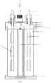
- each vertical vessel (12) is interconnected through the interconnected base (15) that comprises a sump feed (23) and each vertical vessel (12) is independent from one another and each vertical vessel (12) is fed by the vertical and central feed vessel (13), which is interconnected with all the vertical vessels (12) through the sump feed (23) of the interconnected base (15).
- the cylinders (9) comprise:
- the cylinders (9) are fixed in the vertical shaft (8), preferably being at a distance of about 10 mm from each other; and the cylinders (9) rotate around its own axis.
- the system for rotating (10) comprises a motor, not represented in the figures, to rotate at least one vertical shaft (8), not represented in the figures, wherein the motor rotates synchronously each of the vertical shafts (8).
- the vertical shaft (8) comprises cylinders (9) which are equally distant from each other and arranged in series.
- the cylinder (9), as represented in the figure 1 comprises a cylindrical shape, a sampling surface including:
- the use of a cylinder (9) with a higher surface area increases the sampling area, improving the homogeneity of biofilm and decreasing the effects of changes in flow patterns in the boundaries of each cylinder, a phenomenon commonly observed in alternative reactors.
- the cylinder (9) may be made of only one material or different materials simultaneously, such as:
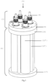
- the present invention comprises a reactor for biofilm formation (3).
- the platform for biofilm formation (2) represented in the figure 2 , comprises:
- the number of the vertical insertion holes (18') and the vertical cavities (20') is equal to the number of the vertical vessels (12'), as represented in the figures 3 and 9 .
- each of the vertical vessels (12') of the reactor for biofilm inactivation and removal from the adhesion surface (5) are independent from one another.
- the reactor for biofilm formation (3) overcomes the limitations of prior art technologies and their main advantages are:
- the step of ii) biofilm formation when the reactor for biofilm formation (3) operates under batch operating conditions, comprises the following substeps:
- the sterile diluted nutrient medium (26), used for biofilm formation comprises 100-fold diluted carbon, nitrogen and phosphorous sources from the initial nutrient medium (25) in adequate buffer, for example, phosphate buffer.
- the table 2 describes the possible composition of the initial nutrient medium (25) and of the feeding medium for biofilm formation by Bacillus cereus or/and Escherichia coli or/and Pseudomonas fluorescens or/and Staphylococcus aureus (single- or mixed-biofilms).
- Table 2 composition of the initial nutrient medium (25) and of the feeding medium for biofilm formation by Bacillus cereus or/and Escherichia coli or/and Pseudomonas fluorescens or/and Staphylococcus aureus (single- or mixed-biofilms)
- Initial concentration g/L
- Fed concentration g/L
- Peptone 0.0 - 2.5 0.0 - 0.025
- Yeast extract 0.0 - 5.0 0.0 - 0.05 Glucose 0.0 - 5.0 0.0 - 0.05 Tryptone 0.0 - 17.0 0.0 - 0.17
- Beef infusion solids 0.0 - 2.0 0.0 - 0.02
- Sodium pyruvate 0.0 - 0.3 0.0 - 0.003
- Biofilm is formed on the surface of each cylinder (9), in the reactor for biofilm formation (3), which comprises:
Landscapes
- Life Sciences & Earth Sciences (AREA)
- Organic Chemistry (AREA)
- Health & Medical Sciences (AREA)
- Chemical & Material Sciences (AREA)
- Engineering & Computer Science (AREA)
- Bioinformatics & Cheminformatics (AREA)
- Microbiology (AREA)
- Zoology (AREA)
- Wood Science & Technology (AREA)
- General Engineering & Computer Science (AREA)
- Genetics & Genomics (AREA)
- General Health & Medical Sciences (AREA)
- Biochemistry (AREA)
- Biomedical Technology (AREA)
- Biotechnology (AREA)
- Sustainable Development (AREA)
- Environmental & Geological Engineering (AREA)
- Clinical Laboratory Science (AREA)
- Water Supply & Treatment (AREA)
- Hydrology & Water Resources (AREA)
- Biodiversity & Conservation Biology (AREA)
- Apparatus Associated With Microorganisms And Enzymes (AREA)
Claims (8)
- Ein Reaktor zur Biofilmbildung (3), umfassend einen Kopf (1) für einen Reaktor zur Biofilmbildung (3), umfassend:einen Hauptdeckel (6), wobei der Hauptdeckel (6) umfasst:eine Vielzahl vertikaler Öffnungen (7), wobei in jede der vertikalen Öffnungen (7) eine vertikale Welle (8) eingesetzt istwobei jede vertikale Welle (8) eine Vielzahl feststehender Zylinder (9) umfasst, wobei die Zylinder (9) in Reihe angeordnet sind; und der Kopf (1) ferner umfasst:ein System zum Drehen (10) jeder einzelnen vertikalen Welle (8) um ihre eigene Achse;wobei der Kopf (1) in eine Plattform zur Biofilmbildung (2) eingesetzt ist, wobei die Plattform zur Biofilmbildung (2) umfasst:- einen Zuführ- und Abflussdeckel (11);- eine Vielzahl vertikaler Behälter (12), bevorzugt vier vertikale Behälter (12);- einen vertikalen und zentralen Zuführbehälter (13);- eine Vielzahl vertikaler Stützwellen (14), bevorzugt vier vertikale Stützwellen (14); und- eine verbundene Grundplatte (15);und die vertikale Welle (8):- in dem Hauptdeckel (6) gehalten wird; und- im Inneren des Behälters (12) aufgehängt ist;wobei der Zuführ- und Abflussdeckel (11) umfasst:- eine Vielzahl vertikaler Einführungsöffnungen (18) zum Einführen von jeweils vier entsprechenden vertikalen Behältern (12);- eine zentrale Zuführöffnung (19) zum Einführen des entsprechenden vertikalen und zentralen Zuführbehälters (13);- eine Vielzahl vertikaler Hohlräume (20), die sich am Boden des Zuführ- und Abflussdeckels (11) befinden, zur Aufnahme des entsprechenden vertikalen Behälters (12);- eine Vielzahl vertikaler Stützöffnungen (21) zum Einsetzen der jeweils entsprechenden vier vertikalen Stützwellen (14); und- eine Vielzahl horizontaler Abflussöffnungen (22), die sich an der Seitenfläche des Zuführ- und Abflussdeckels (11) befinden, um den entsprechenden vertikalen Behälter (12) zu entleeren;und den Zuführ- und Abflussdeckel (11), ferner umfassend ein System für die Zufuhr und den Abfluss, das eine externe Pumpe für die Versorgung des vertikalen und zentralen Zuführbehälters (13) durch einen externen Schlauch umfasst.
- Der Reaktor zur Biofilmbildung (3) nach Anspruch 1, wobei der vertikale Behälter (12) dicht ist und umfasst:- eine röhrenförmige Form; und- ein Arbeitsvolumen, umfassend:- einen Durchmesser von etwa 27 bis etwa 108 mm; und- eine Länge von etwa 136 bis etwa 544 mm,und jeder vertikaler Behälter (12) durch die verbundene Grundplatte (15) verbunden ist, die eine Sumpf-Zuführung (23) umfasst;und jeder vertikale Behälter (12) durch den vertikalen und zentralen Zuführbehälter (13) versorgt wird, der mit allen vertikalen Behältern (12) durch die Sumpf-Zuführung (23) der verbundenen Grundplatte (15) verbunden ist.
- Der Reaktor zur Biofilmbildung (3) nach einem der Ansprüche 1 oder 2, wobei die Zylinder (9) umfassen:- eine zylindrische Form;- eine Entnahmeoberfläche;- eine Längsöffnung (27) zum Einführen in die vertikale Welle (8); und- einen Fixierungsabschnitt,und die Zylinder (9) aus einem Werkstoff hergestellt sind, der aus der nachstehenden Liste ausgewählt ist, bestehend aus:- Metallen;- Metalllegierungen;- Kunststoffen;- Glas; und- Beschichtungen und Oberflächenschichten, wobei die Beschichtungen und Oberflächenschichten ein Nanomaterial oder eine chemisch modifizierte Oberfläche umfassen;und die Zylinder (9) in der vertikalen Welle (8) befestigt sind; und die Zylinder (9) sich um ihre eigene Achse drehen.
- Der Reaktor zur Biofilmbildung (3) nach einem der Ansprüche 1 oder 2 oder 3, wobei die verbundene Grundplatte (15) umfasst:- eine Vielzahl von Hohlräumen in der Bodenplatte (28) zur Aufnahme des entsprechenden vertikalen Behälters (12);- eine Vielzahl von Hohlräumen in der Bodenplatte als Abstützung (29), in die die entsprechende vertikale Stützwelle (14) eingesetzt wird;- eine horizontale Lecköffnung (30), die sich an der Seitenfläche der Bodenplatte (15) befindet, um die Sumpf-Zuführung (23) zu entleeren;- einen zentralen Hohlraum in der Bodenplatte (31) zur Aufnahme eines vertikalen und zentralen Zuführbehälters (13); und- die Sumpf-Zuführung (23) sich unmittelbar unter dem zentralen Hohlraum in der Bodenplatte (31) befindet und auch unter jedem der entsprechenden vertikalen Behälter (12).
- Der Reaktor zur Biofilmbildung (3) nach Anspruch 4, wobei die verbundene Grundplatte (15) des Reaktors zur Biofilmbildung (3) Hohlräume in der Bodenplatte (28) in einer Anzahl aufweist, die der Anzahl der vertikalen Behälter (12) entspricht.
- Der Reaktor zur Biofilmbildung (3) nach einem der Ansprüche 1 oder 2 oder 3 oder 4 oder 5, wobei das System zum Drehen (10) einen Motor umfasst, um eine Vielzahl vertikaler Wellen (8) zu drehen, wobei der Motor jede der vertikalen Wellen (8) synchron dreht, und das System zum Drehen (10) ferner umfasst:- eine Riemenscheibe (32), die an der vertikalen Welle (8) befestigt ist;- einen Riemenspanner (33); und- einen Synchronriemen, der die vier vertikalen Wellen (8) miteinander verbindet, um jede der vertikalen Wellen (8) mit Hilfe des Motors synchron zu drehen.
- Ein Verfahren zur Biofilmbildung, gekennzeichnet durch die Verwendung des Reaktors zur Biofilmbildung (3) nach einem der Ansprüche 1 oder 2 oder 3 oder 4 oder 5 oder 6 und umfassend die folgenden Schritte:i) Reinigen und Desinfizieren des Reaktors zur Biofilmbildung unter Verwendung eines chemischen Mittels (3); undii) Biofilmbildung durch Verwendung des Reaktors zur Biofilmbildung (3), wobei:- der Schritt ii) der Biofilmbildung unter Bedingungen für den Batchbetrieb durchgeführt wird; oder- der Schritt ii) der Biofilmbildung unter Bedingung für den Fed-Batchbetrieb durchgeführt wird; oder- der Schritt ii) der Biofilmbildung unter kontinuierlichen Betriebsbedingungen durchgeführt wird.
- Das Verfahren zur Biofilmbildung nach Anspruch 7, wobei der Schritt ii) der Biofilmbildung die folgenden Teilschritte umfasst:ii.i) Befüllen der vertikalen Behälter (12) durch den vertikalen und zentralen Zuführbehälter (13) mit der Bakterienkultur (24);ii.ii) Befüllen der vertikalen Behälter (12) über den vertikalen und zentralen Zuführbehälter (13) mit dem Anfangsnährmedium (25);ii.iii) Versorgen der vertikalen Behälter (12) mit sterilem verdünntem Nährmedium (26) mit Hilfe der externen Pumpe (29) über einen externen Schlauch, der direkt mit dem vertikalen und zentralen Zuführbehälter (13) verbunden ist, wenn die Anlage im Fed-Batch- oder Dauerbetrieb betrieben wird; undii.iv) Drehen der Zylinder (9) über einen Zeitraum von etwa 24 h bis zu mehreren Monaten und mit einer Drehzahl von 0 bis etwa 2000 U/min um ihre eigene Achse.
Applications Claiming Priority (2)
| Application Number | Priority Date | Filing Date | Title |
|---|---|---|---|
| PT11591219 | 2019-11-14 | ||
| PCT/IB2019/060443 WO2021094819A1 (en) | 2019-11-14 | 2019-12-04 | A head for a reactor for biofilm formation, reactor for biofilm formation, reactor for biofilm inactivation and removal from the adhesion surface, and related process for biofilm formation and process for biofilm inactivation and removal from the adhesion surface |
Publications (3)
| Publication Number | Publication Date |
|---|---|
| EP4058413A1 EP4058413A1 (de) | 2022-09-21 |
| EP4058413C0 EP4058413C0 (de) | 2025-04-16 |
| EP4058413B1 true EP4058413B1 (de) | 2025-04-16 |
Family
ID=69187817
Family Applications (1)
| Application Number | Title | Priority Date | Filing Date |
|---|---|---|---|
| EP19842400.4A Active EP4058413B1 (de) | 2019-11-14 | 2019-12-04 | Reaktor zur biofilmbildung und verfahren zur biofilmbildung |
Country Status (2)
| Country | Link |
|---|---|
| EP (1) | EP4058413B1 (de) |
| WO (1) | WO2021094819A1 (de) |
Families Citing this family (3)
| Publication number | Priority date | Publication date | Assignee | Title |
|---|---|---|---|---|
| CN114717084B (zh) * | 2022-04-29 | 2025-08-22 | 振德医疗用品股份有限公司 | 一种生物膜培养模拟装置及其模拟培养创面生物膜的方法 |
| CN115449453A (zh) * | 2022-09-19 | 2022-12-09 | 天津大学 | 一种给水管壁生物膜分级培养装置 |
| CN119100516B (zh) * | 2024-10-18 | 2025-07-25 | 江西绿建环保科技有限公司 | 一种废水处理用双氧层生物膜反应器 |
Family Cites Families (2)
| Publication number | Priority date | Publication date | Assignee | Title |
|---|---|---|---|---|
| JP3639007B2 (ja) * | 1995-08-22 | 2005-04-13 | 京都水研株式会社 | 攪拌槽型のバイオリアクタ |
| JP4986659B2 (ja) * | 2006-03-23 | 2012-07-25 | 藤森工業株式会社 | 培養袋及び培養器 |
-
2019
- 2019-12-04 EP EP19842400.4A patent/EP4058413B1/de active Active
- 2019-12-04 WO PCT/IB2019/060443 patent/WO2021094819A1/en not_active Ceased
Non-Patent Citations (1)
| Title |
|---|
| GOMES I.B. ET AL: "The action of chemical and mechanical stresses on single and dual species biofilm removal of drinking water bacteria", SCIENCE OF THE TOTAL ENVIRONMENT, vol. 631-632, 1 August 2018 (2018-08-01), AMSTERDAM, NL, pages 987 - 993, XP093054690, ISSN: 0048-9697, DOI: 10.1016/j.scitotenv.2018.03.042 * |
Also Published As
| Publication number | Publication date |
|---|---|
| EP4058413A1 (de) | 2022-09-21 |
| WO2021094819A1 (en) | 2021-05-20 |
| EP4058413C0 (de) | 2025-04-16 |
Similar Documents
| Publication | Publication Date | Title |
|---|---|---|
| McBain | In vitro biofilm models: an overview | |
| McLandsborough et al. | Biofilms: at the interface between biophysics and microbiology | |
| Peters et al. | A constant-depth laboratory model film fermenter | |
| AU724282B2 (en) | Biofilm incubation | |
| Merritt et al. | Growing and analyzing static biofilms | |
| Goeres et al. | A method for growing a biofilm under low shear at the air–liquid interface using the drip flow biofilm reactor | |
| US10309951B2 (en) | Bioreactor for the in situ study of microbial biofilms inducing corrosion on metal surfaces | |
| JP2009055920A (ja) | 微小発酵器デバイスおよび細胞ベースのスクリーニング法 | |
| Fowler | Microbial adhesion to surfaces | |
| JPH0943229A (ja) | 生物殺菌剤の透過力評価の生物膜厚さモデル方法と装置 | |
| EP4058413A1 (de) | Kopf für einen reaktor zur biofilmbildung, reaktor zur biofilmbildung, reaktor zur inaktivierung und entfernung des biofilms von der adhäsionsfläche und verfahren zur biofilmbildung und verfahren zur inaktivierung und entfernung des biofilms von der adhäsionsfläche | |
| Ramachandra et al. | Evaluating models and assessment techniques for understanding oral biofilm complexity | |
| Sternberg et al. | Methods for dynamic investigations of surface-attached in vitro bacterial and fungal biofilms | |
| CN102459560A (zh) | 可消耗组分试剂盒 | |
| Goeres et al. | Design and fabrication of biofilm reactors | |
| Burman et al. | Techniques for the assessment of growth of micro‐organisms on plumbing materials used in contact with potable water supplies | |
| Dibdin et al. | [23] Steady-state biofilm: Practical and theoretical models | |
| GRIEBE et al. | Rotating Annular Reactors | |
| Simões et al. | A comparative study of drinking water biofilm monitoring with flow cell and Propella™ bioreactors | |
| Matthews | Fermentation equipment selection: laboratory scale bioreactor design considerations | |
| Harding et al. | In Vitro Assessment of Biofilm Formation by Soil‐and Plant‐Associated Microorganisms | |
| Putri | Understanding thermophilic spore-forming bacteria in milk powders | |
| McLeod et al. | A standard 96-well based high throughput microfluidic perfusion biofilm reactor for in situ optical analysis | |
| Buswell et al. | [5] Use of continuous culture bioreactors for the study of pathogens such as Campylobacter jejuni and Escherichia coli O 157 in biofilms | |
| EP2670859B1 (de) | Verfahren zum sammeln repräsentativer mikrobiologischer wasserproben |
Legal Events
| Date | Code | Title | Description |
|---|---|---|---|
| STAA | Information on the status of an ep patent application or granted ep patent |
Free format text: STATUS: UNKNOWN |
|
| STAA | Information on the status of an ep patent application or granted ep patent |
Free format text: STATUS: THE INTERNATIONAL PUBLICATION HAS BEEN MADE |
|
| PUAI | Public reference made under article 153(3) epc to a published international application that has entered the european phase |
Free format text: ORIGINAL CODE: 0009012 |
|
| STAA | Information on the status of an ep patent application or granted ep patent |
Free format text: STATUS: REQUEST FOR EXAMINATION WAS MADE |
|
| 17P | Request for examination filed |
Effective date: 20220613 |
|
| AK | Designated contracting states |
Kind code of ref document: A1 Designated state(s): AL AT BE BG CH CY CZ DE DK EE ES FI FR GB GR HR HU IE IS IT LI LT LU LV MC MK MT NL NO PL PT RO RS SE SI SK SM TR |
|
| DAV | Request for validation of the european patent (deleted) | ||
| DAX | Request for extension of the european patent (deleted) | ||
| STAA | Information on the status of an ep patent application or granted ep patent |
Free format text: STATUS: EXAMINATION IS IN PROGRESS |
|
| 17Q | First examination report despatched |
Effective date: 20230622 |
|
| REG | Reference to a national code |
Ref country code: DE Ref legal event code: R079 Free format text: PREVIOUS MAIN CLASS: C02F0003080000 Ipc: C12M0003060000 Ref document number: 602019068796 Country of ref document: DE |
|
| RIC1 | Information provided on ipc code assigned before grant |
Ipc: C12M 1/12 20060101ALI20240920BHEP Ipc: C02F 3/34 20060101ALI20240920BHEP Ipc: C02F 3/10 20060101ALI20240920BHEP Ipc: C12M 1/00 20060101ALI20240920BHEP Ipc: C02F 3/08 20060101ALI20240920BHEP Ipc: C12M 3/06 20060101AFI20240920BHEP |
|
| GRAP | Despatch of communication of intention to grant a patent |
Free format text: ORIGINAL CODE: EPIDOSNIGR1 |
|
| STAA | Information on the status of an ep patent application or granted ep patent |
Free format text: STATUS: GRANT OF PATENT IS INTENDED |
|
| INTG | Intention to grant announced |
Effective date: 20241113 |
|
| GRAS | Grant fee paid |
Free format text: ORIGINAL CODE: EPIDOSNIGR3 |
|
| GRAA | (expected) grant |
Free format text: ORIGINAL CODE: 0009210 |
|
| STAA | Information on the status of an ep patent application or granted ep patent |
Free format text: STATUS: THE PATENT HAS BEEN GRANTED |
|
| AK | Designated contracting states |
Kind code of ref document: B1 Designated state(s): AL AT BE BG CH CY CZ DE DK EE ES FI FR GB GR HR HU IE IS IT LI LT LU LV MC MK MT NL NO PL PT RO RS SE SI SK SM TR |
|
| REG | Reference to a national code |
Ref country code: GB Ref legal event code: FG4D |
|
| REG | Reference to a national code |
Ref country code: CH Ref legal event code: EP Ref country code: DE Ref legal event code: R096 Ref document number: 602019068796 Country of ref document: DE |
|
| REG | Reference to a national code |
Ref country code: IE Ref legal event code: FG4D |
|
| U01 | Request for unitary effect filed |
Effective date: 20250514 |
|
| U07 | Unitary effect registered |
Designated state(s): AT BE BG DE DK EE FI FR IT LT LU LV MT NL PT RO SE SI Effective date: 20250520 |
|
| PG25 | Lapsed in a contracting state [announced via postgrant information from national office to epo] |
Ref country code: ES Free format text: LAPSE BECAUSE OF FAILURE TO SUBMIT A TRANSLATION OF THE DESCRIPTION OR TO PAY THE FEE WITHIN THE PRESCRIBED TIME-LIMIT Effective date: 20250416 |
|
| PG25 | Lapsed in a contracting state [announced via postgrant information from national office to epo] |
Ref country code: NO Free format text: LAPSE BECAUSE OF FAILURE TO SUBMIT A TRANSLATION OF THE DESCRIPTION OR TO PAY THE FEE WITHIN THE PRESCRIBED TIME-LIMIT Effective date: 20250716 Ref country code: GR Free format text: LAPSE BECAUSE OF FAILURE TO SUBMIT A TRANSLATION OF THE DESCRIPTION OR TO PAY THE FEE WITHIN THE PRESCRIBED TIME-LIMIT Effective date: 20250717 |
|
| PG25 | Lapsed in a contracting state [announced via postgrant information from national office to epo] |
Ref country code: PL Free format text: LAPSE BECAUSE OF FAILURE TO SUBMIT A TRANSLATION OF THE DESCRIPTION OR TO PAY THE FEE WITHIN THE PRESCRIBED TIME-LIMIT Effective date: 20250416 |
|
| PG25 | Lapsed in a contracting state [announced via postgrant information from national office to epo] |
Ref country code: HR Free format text: LAPSE BECAUSE OF FAILURE TO SUBMIT A TRANSLATION OF THE DESCRIPTION OR TO PAY THE FEE WITHIN THE PRESCRIBED TIME-LIMIT Effective date: 20250416 |
|
| PG25 | Lapsed in a contracting state [announced via postgrant information from national office to epo] |
Ref country code: RS Free format text: LAPSE BECAUSE OF FAILURE TO SUBMIT A TRANSLATION OF THE DESCRIPTION OR TO PAY THE FEE WITHIN THE PRESCRIBED TIME-LIMIT Effective date: 20250716 |
|
| PG25 | Lapsed in a contracting state [announced via postgrant information from national office to epo] |
Ref country code: IS Free format text: LAPSE BECAUSE OF FAILURE TO SUBMIT A TRANSLATION OF THE DESCRIPTION OR TO PAY THE FEE WITHIN THE PRESCRIBED TIME-LIMIT Effective date: 20250816 |
|
| U20 | Renewal fee for the european patent with unitary effect paid |
Year of fee payment: 7 Effective date: 20251119 |
|
| PG25 | Lapsed in a contracting state [announced via postgrant information from national office to epo] |
Ref country code: SM Free format text: LAPSE BECAUSE OF FAILURE TO SUBMIT A TRANSLATION OF THE DESCRIPTION OR TO PAY THE FEE WITHIN THE PRESCRIBED TIME-LIMIT Effective date: 20250416 |
|
| PG25 | Lapsed in a contracting state [announced via postgrant information from national office to epo] |
Ref country code: CZ Free format text: LAPSE BECAUSE OF FAILURE TO SUBMIT A TRANSLATION OF THE DESCRIPTION OR TO PAY THE FEE WITHIN THE PRESCRIBED TIME-LIMIT Effective date: 20250416 |
|
| PG25 | Lapsed in a contracting state [announced via postgrant information from national office to epo] |
Ref country code: SK Free format text: LAPSE BECAUSE OF FAILURE TO SUBMIT A TRANSLATION OF THE DESCRIPTION OR TO PAY THE FEE WITHIN THE PRESCRIBED TIME-LIMIT Effective date: 20250416 |
|
| PLBE | No opposition filed within time limit |
Free format text: ORIGINAL CODE: 0009261 |
|
| STAA | Information on the status of an ep patent application or granted ep patent |
Free format text: STATUS: NO OPPOSITION FILED WITHIN TIME LIMIT |
|
| REG | Reference to a national code |
Ref country code: CH Ref legal event code: L10 Free format text: ST27 STATUS EVENT CODE: U-0-0-L10-L00 (AS PROVIDED BY THE NATIONAL OFFICE) Effective date: 20260225 |
|
| 26N | No opposition filed |
Effective date: 20260119 |